WO2016184101A1 - 一种虚拟小区动态的控制面信令的传递方法及系统 - Google Patents
一种虚拟小区动态的控制面信令的传递方法及系统 Download PDFInfo
- Publication number
- WO2016184101A1 WO2016184101A1 PCT/CN2015/098452 CN2015098452W WO2016184101A1 WO 2016184101 A1 WO2016184101 A1 WO 2016184101A1 CN 2015098452 W CN2015098452 W CN 2015098452W WO 2016184101 A1 WO2016184101 A1 WO 2016184101A1
- Authority
- WO
- WIPO (PCT)
- Prior art keywords
- base station
- transmitting
- control plane
- signaling
- serving base
- Prior art date
- Legal status (The legal status is an assumption and is not a legal conclusion. Google has not performed a legal analysis and makes no representation as to the accuracy of the status listed.)
- Ceased
Links
Images



Classifications
-
- H—ELECTRICITY
- H04—ELECTRIC COMMUNICATION TECHNIQUE
- H04W—WIRELESS COMMUNICATION NETWORKS
- H04W36/00—Hand-off or reselection arrangements
- H04W36/13—Cell handover without a predetermined boundary, e.g. virtual cells
-
- H—ELECTRICITY
- H04—ELECTRIC COMMUNICATION TECHNIQUE
- H04W—WIRELESS COMMUNICATION NETWORKS
- H04W72/00—Local resource management
- H04W72/50—Allocation or scheduling criteria for wireless resources
- H04W72/54—Allocation or scheduling criteria for wireless resources based on quality criteria
-
- H—ELECTRICITY
- H04—ELECTRIC COMMUNICATION TECHNIQUE
- H04W—WIRELESS COMMUNICATION NETWORKS
- H04W40/00—Communication routing or communication path finding
- H04W40/02—Communication route or path selection, e.g. power-based or shortest path routing
- H04W40/04—Communication route or path selection, e.g. power-based or shortest path routing based on wireless node resources
-
- H—ELECTRICITY
- H04—ELECTRIC COMMUNICATION TECHNIQUE
- H04W—WIRELESS COMMUNICATION NETWORKS
- H04W72/00—Local resource management
- H04W72/20—Control channels or signalling for resource management
- H04W72/23—Control channels or signalling for resource management in the downlink direction of a wireless link, i.e. towards a terminal
-
- H—ELECTRICITY
- H04—ELECTRIC COMMUNICATION TECHNIQUE
- H04W—WIRELESS COMMUNICATION NETWORKS
- H04W74/00—Wireless channel access
- H04W74/002—Transmission of channel access control information
- H04W74/006—Transmission of channel access control information in the downlink, i.e. towards the terminal
-
- H—ELECTRICITY
- H04—ELECTRIC COMMUNICATION TECHNIQUE
- H04W—WIRELESS COMMUNICATION NETWORKS
- H04W76/00—Connection management
- H04W76/20—Manipulation of established connections
- H04W76/27—Transitions between radio resource control [RRC] states
-
- H—ELECTRICITY
- H04—ELECTRIC COMMUNICATION TECHNIQUE
- H04W—WIRELESS COMMUNICATION NETWORKS
- H04W36/00—Hand-off or reselection arrangements
- H04W36/0005—Control or signalling for completing the hand-off
- H04W36/0055—Transmission or use of information for re-establishing the radio link
- H04W36/0069—Transmission or use of information for re-establishing the radio link in case of dual connectivity, e.g. decoupled uplink/downlink
-
- H—ELECTRICITY
- H04—ELECTRIC COMMUNICATION TECHNIQUE
- H04W—WIRELESS COMMUNICATION NETWORKS
- H04W84/00—Network topologies
- H04W84/18—Self-organising networks, e.g. ad-hoc networks or sensor networks
- H04W84/20—Leader-follower arrangements
-
- H—ELECTRICITY
- H04—ELECTRIC COMMUNICATION TECHNIQUE
- H04W—WIRELESS COMMUNICATION NETWORKS
- H04W88/00—Devices specially adapted for wireless communication networks, e.g. terminals, base stations or access point devices
- H04W88/08—Access point devices
Definitions
- This application relates to, but is not limited to, wireless communication technologies.
- the main means to improve network throughput include: increasing the transmission rate of point-to-point links, spreading spectrum resources, and high-density deployment of heterogeneous networks; among them, high-density deployment of heterogeneous networks will support 20 to 30 times of current traffic.
- UDN high-density network
- the spatial multiplexing rate of spectrum resources is increased by reducing the coverage area of the cell.
- the UDN station can provide better link quality, since the coverage area of the small station is small and cannot support the user's fast movement well, a new solution technology is also proposed, such as introducing a virtual cell.
- the virtual cell is composed of three base stations (BS, Base Station), including one primary serving base station (Master BS) and two secondary serving base stations (Slave BS).
- BS Base Station
- Master BS primary serving base station
- Slave BS secondary serving base stations
- MS Mobile Station
- MS Mobile Station
- control plane signaling is sent to the user at the primary serving base station, but in reality, the primary serving base station is also a small cell, in order to enable control plane signaling to be more reliably received by the user. It is usually necessary to frequently replace the primary serving base station, thereby ensuring that the primary serving base station from the user's perspective is always the base station that has the best channel quality connection with the user. But this is frequent
- the change of the primary service base station involves frequent synchronization of control plane signaling and user plane data, which is not conducive to the L2 virtualization process.
- the embodiment of the invention provides a method and a system for transmitting control plane signaling of a virtual cell dynamic, which can solve the problem of frequently replacing the primary serving base station in order to enable the control plane signaling to be reliably received in the related art.
- An embodiment of the present invention provides a method for transmitting control plane signaling of a virtual cell dynamic, comprising: a transmitting end selecting a base station as a control plane signaling transmission channel in a set of base stations configured as a virtual cell; The selected base station transmits the control plane signaling to the receiving end.
- the embodiment of the present invention further provides a virtual cell dynamic control plane signaling delivery system, including: a selection module, configured to: select a base station as a control plane signaling transmission channel in a set of base stations configured as a virtual cell; And being configured to: pass the control plane signaling to the receiving end by using the selected base station.
- a selection module configured to: select a base station as a control plane signaling transmission channel in a set of base stations configured as a virtual cell; And being configured to: pass the control plane signaling to the receiving end by using the selected base station.
- the embodiment of the present invention further provides a computer readable storage medium storing computer executable instructions for performing the method of any of the above.
- the transmitting end selects a base station that is a control plane signaling transmission channel in a set of base stations that are configured as a virtual cell, and transmits control plane signaling to the receiving end by using the selected base station.
- a base station that is a control plane signaling transmission channel in a set of base stations that are configured as a virtual cell
- transmits control plane signaling to the receiving end by using the selected base station in the transmission process of the control plane signaling, the frequent replacement of the primary serving base station is avoided, and the control plane signaling can be reliably transmitted between the network side and the user, which reduces the frequent change of the primary
- the serving base station causes a problem of control plane signaling data synchronization and service data synchronization between the source primary serving base station and the target primary serving base station, and reduces backhaul transmission overhead between the base stations.
- FIG. 1 is a schematic diagram of a virtual cell when an ultra-dense cell is deployed in the related art
- FIG. 2 is a flowchart of a method for transmitting control plane signaling of a virtual cell according to an embodiment of the present invention
- FIG. 3 is a schematic diagram of a user plane protocol stack of signaling data transmitted between a primary serving base station and a secondary serving base station according to an embodiment of the present invention
- FIG. 4 is a schematic diagram of signaling of downlink control plane signaling according to an embodiment of the present invention.
- FIG. 5 is a schematic diagram of signaling of downlink control plane signaling according to an embodiment of the present invention.
- FIG. 6 is a schematic diagram of signaling of uplink control plane signaling according to an embodiment of the present invention.
- FIG. 7 is a schematic diagram of signaling of uplink control plane signaling according to an embodiment of the present invention.
- FIG. 8 is a schematic diagram of a control system for transmitting control plane signaling of a virtual cell according to an embodiment of the present invention.
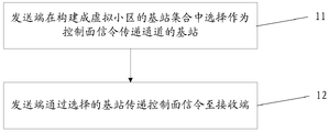
- FIG. 2 is a flowchart of a method for transmitting control plane signaling of a virtual cell according to an embodiment of the present invention. As shown in FIG. 2, the method for transmitting control plane signaling of a virtual cell according to an embodiment of the present invention includes the following steps:
- Step 11 The transmitting end selects a base station as a control plane signaling transmission channel among the set of base stations constructed as a virtual cell.
- Step 12 The transmitting end transmits control plane signaling to the receiving end through the selected base station.
- the transmitting end transmitting the control plane signaling to the receiving end by the selected base station includes: the transmitting end completely transmitting the signaling data of an RRC message to the receiving end by using the selected base station.
- the transmitting end is the primary serving base station, and the receiving end is the user equipment.
- the transmitting end is a user equipment
- the receiving end is a primary serving base station.
- the set of base stations constructed as virtual cells includes pre-established for transmission and connection.
- the primary serving base station and the secondary serving base station of the radio bearer receiving the signaling data of the RRC message.
- the user plane of the primary serving base station has a Packet Data Convergence Protocol (PDCP), a Radio Link Control Protocol (RLC), a Media Access Control (MAC), and a physical layer ( PHY) protocol stack.
- PDCP Packet Data Convergence Protocol
- RLC Radio Link Control Protocol
- MAC Media Access Control
- PHY physical layer
- the transmitting end is, for example, a master serving base station (Master BS), and the receiving end is, for example, a user equipment.
- Master BS master serving base station
- the receiving end is, for example, a user equipment.
- the transmitting end selects a signaling from the serving base station as a delivery RRC message in a set of base stations configured as a virtual cell.
- the transmitting end transmits the control plane signaling to the receiving end through the selected base station, and includes: the radio link control layer protocol RLC protocol data unit (PDU, Protocol) of the signaling radio bearer (SRB, Signal Radio Bearer) Data Unit) is passed to the slave base station.
- PDU radio link control layer protocol RLC protocol data unit
- SRB Signal Radio Bearer
- the transmitting end selects an appropriate base station as a base station of the control plane signaling transmission channel, for example, according to the quality of the base station transmission command and the resource utilization situation, among the base station sets constructed as the virtual cell.
- FIG. 4 is a schematic diagram of signaling of downlink control plane signaling according to an embodiment of the present invention.
- the three base stations constitute a virtual cell for the user, wherein the base station 1 is a master serving base station (Master-BS), and the base stations 2 and 3 are slave service base stations (Slave-BS), respectively, and are respectively called slaves.
- - BS1 from serving base station 1
- Slave-BS2 from serving base station 2).
- the direction of the arrow in Figure 4 is the flow direction of the downlink control plane signaling.
- the process of transmitting data of the downlink control plane signaling in the time period from T1 to T2 includes the following steps:
- Step 101 The Master-BS constructs an RRC message, and selects Slave-BS2 as a base station that transmits the RRC message in the set of base stations that are configured as a virtual cell, where the Radio Resource Control (RRC) protocol of the Master-BS is used.
- RRC Radio Resource Control
- Stack to manage RRC messages (including generation, modification, and deletion);
- Step 102 The RRC layer of the Master-BS transmits the RRC message to the user plane of the Master-BS, and indicates to the target base station and/or the target cell to be delivered to the user plane;
- Step 103 The user plane of the Master-BS transmits the signaling data PDU to the user of the Slave-BS2. surface;
- Step 104 After receiving the signaling data, the user plane of the Slave-BS2 is delivered to the user equipment (UE) through the air interface channel;
- UE user equipment
- Step 105 After receiving the signaling data, the user plane of the UE is delivered to the RRC layer of the UE through the air interface.
- FIG. 5 is a schematic diagram of signaling of downlink control plane signaling according to an embodiment of the present invention.
- the three base stations constitute a virtual cell for the user, wherein the base station 1 is a master serving base station (Master-BS), and the base stations 2 and 3 are slave service base stations (Slave-BS), respectively, and are respectively called slaves.
- - BS1 from serving base station 1
- Slave-BS2 from serving base station 2).
- the direction of the arrow in Figure 5 is the flow of downlink control plane signaling.
- the process of transmitting data in the downlink control plane signaling in the T3 to T4 time period includes the following steps:
- Step 201 The Master-BS constructs an RRC message, and selects the Master-BS itself as a base station that transmits the RRC message in the set of base stations configured as a virtual cell, where the RRC message is managed by the RRC protocol stack of the Master-BS (including generation , modification and deletion);
- Step 202 The RRC layer of the Master-BS transmits the RRC message to the user plane of the Master-BS, and indicates to the target base station and/or the target cell to be delivered to the user plane;
- Step 203 The user plane of the master-BS transmits the signaling data to the user (UE) through the air interface channel of the base station;
- Step 204 After receiving the signaling data, the user plane of the UE is delivered to the RRC layer of the UE through the air interface.
- FIG. 6 is a schematic diagram of signaling of uplink control plane signaling according to an embodiment of the present invention.
- the three base stations constitute a virtual cell for the user, wherein the base station 1 is a master serving base station (Master-BS), and the base stations 2 and 3 are slave service base stations (Slave-BS), respectively, and are respectively called slaves.
- - BS1 from serving base station 1
- Slave-BS2 from serving base station 2).
- the direction of the arrow in Figure 6 is the flow direction of the uplink control plane signaling.
- the process of transmitting data of the uplink control plane signaling in the time period from Tu1 to Tu2 includes the following steps:
- Step 301 The RRC layer of the UE constructs an RRC message, and selects Slave-BS1 as a base station that transmits the RRC message in the set of base stations that are configured as a virtual cell, where the RRC message is managed by the RRC protocol stack of the UE (including generation and modification). And delete);
- Step 302 The RRC layer of the UE delivers the RRC message to the user plane of the UE, and indicates to the target base station and/or the target cell to be delivered by the user plane;
- Step 303 After receiving the signaling data PDU, the user plane of the UE passes the air interface to the user plane of the Slave-BS1.
- Step 304 After receiving the signaling data, the user plane of the Slave-BS1 is delivered to the user plane of the Master-BS.
- Step 305 After receiving the signaling data, the user plane of the Master-BS is delivered to the RRC layer of the Master-BS.
- FIG. 7 is a schematic diagram of signaling of uplink control plane signaling according to an embodiment of the present invention.
- the three base stations constitute a virtual cell for the user, wherein the base station 1 is a master serving base station (Master-BS), and the base stations 2 and 3 are slave service base stations (Slave-BS), respectively, and are respectively called slaves.
- - BS1 from serving base station 1
- Slave-BS2 from serving base station 2).
- the direction of the arrow in Figure 7 is the flow direction of the uplink control plane signaling.
- the process of transmitting data of the uplink control plane signaling in the time period from Tu3 to Tu4 includes the following steps:
- Step 401 The RRC layer of the UE constructs an RRC message, and selects a Master-BS as a base station that transmits the RRC message in the set of base stations that are configured as a virtual cell, where the RRC message is managed by the RRC protocol stack of the UE (including generation and modification). And delete);
- Step 402 The RRC layer of the UE delivers the RRC message to the user plane of the UE, and indicates the target base station and/or the target cell to be delivered to the user plane;
- Step 403 The user plane of the UE transmits the signaling data PDU to the Master-BS through the air interface;
- Step 404 After receiving the signaling data, the user plane of the Master-BS is delivered to the RRC layer of the Master-BS.
- the embodiment of the present invention further provides a virtual cell dynamic control plane signaling delivery system, including: a selection module 81, configured to: select a base station set configured as a virtual cell As a base station of the control plane signaling transmission channel, the transmitting module 82 is configured to: transmit the control plane signaling to the receiving end by using the selected base station.
- a selection module 81 configured to: select a base station set configured as a virtual cell As a base station of the control plane signaling transmission channel
- the transmitting module 82 is configured to: transmit the control plane signaling to the receiving end by using the selected base station.
- the selection module 81 and the transmission module 82 are disposed at the transmitting end.
- the transmitting end is, for example, a primary serving base station, and correspondingly, the receiving end is, for example, a user equipment.
- the transmitting end is, for example, a user equipment, and the receiving end is, for example, a primary serving base station.
- the transmitting module 82 is configured to: completely transmit signaling data of an RRC message to the receiving end by using the selected base station.
- the base station set constructed as a virtual cell includes a primary serving base station and a secondary serving base station that establish a radio bearer for transmitting and receiving signaling data of an RRC message in advance.
- the user plane of the primary serving base station has a PDCP, RLC, MAC, and PHY protocol stack.
- the MAC and PHY protocol stacks exist from the user plane of the serving base station.
- all or part of the steps of the above embodiments may also be implemented by using an integrated circuit. These steps may be separately fabricated into individual integrated circuit modules, or multiple modules or steps may be fabricated into a single integrated circuit module. achieve.
- the devices/function modules/functional units in the above embodiments may be implemented by a general-purpose computing device, which may be centralized on a single computing device or distributed over a network of multiple computing devices.
- the device/function module/functional unit in the above embodiment When the device/function module/functional unit in the above embodiment is implemented in the form of a software function module and sold or used as a stand-alone product, it can be stored in a computer readable storage medium.
- the above mentioned computer readable storage medium may be a read only memory, a magnetic disk or an optical disk or the like.
- the frequent replacement of the primary serving base station is avoided, and the control plane signaling can be reliably transmitted between the network side and the user, which reduces the frequent change of the primary
- the serving base station causes a problem of control plane signaling data synchronization and service data synchronization between the source primary serving base station and the target primary serving base station, and reduces backhaul transmission overhead between the base stations.
Landscapes
- Engineering & Computer Science (AREA)
- Computer Networks & Wireless Communication (AREA)
- Signal Processing (AREA)
- Quality & Reliability (AREA)
- Mobile Radio Communication Systems (AREA)
Abstract
Description
Claims (12)
- 一种虚拟小区动态的控制面信令的传递方法,包括:发送端在构建成虚拟小区的基站集合中选择作为控制面信令传递通道的基站;所述发送端通过所述选择的基站传递所述控制面信令至接收端。
- 如权利要求1所述的方法,其中:所述发送端通过所述选择的基站传递所述控制面信令至接收端包括:所述发送端通过所述选择的基站完整传递一条无线资源控制RRC消息的信令数据至所述接收端。
- 如权利要求1所述的方法,其中:所述构建成虚拟小区的基站集合包括预先建立用于传递和接收RRC消息的信令数据的无线承载的主服务基站和从服务基站。
- 如权利要求3所述的方法,其中:所述主服务基站的用户面存在分组数据汇聚协议PDCP、无线链路控制层协议RLC、介质访问控制MAC及物理层PHY协议栈,所述从服务基站的用户面存在MAC和PHY协议栈。
- 如权利要求1所述的方法,其中:所述发送端为用户设备,所述接收端为主服务基站。
- 如权利要求1所述的方法,其中:所述发送端为主服务基站,所述接收端为用户设备。
- 如权利要求6所述的方法,其中:当所述发送端在构建成虚拟小区的基站集合中选择从服务基站作为传递RRC消息的信令数据的通道时,所述发送端通过所述选择的基站传递所述控制面信令至接收端包括:所述发送端将信令无线承载SRB的无线链路控制层协议RLC协议数据单元PDU传递给从服务基站。
- 一种虚拟小区动态的控制面信令的传递系统,包括:选择模块,设置为:在构建成虚拟小区的基站集合中选择作为控制面信令传递通道的基站;传递模块,设置为:通过所述选择的基站传递所述控制面信令至接收 端。
- 如权利要求8所述的系统,其中:所述传递模块,是设置为:通过所述选择的基站完整传递一条RRC消息的信令数据至所述接收端。
- 如权利要求8所述的系统,其中:所述构建成虚拟小区的基站集合包括预先建立用于传递和接收RRC消息的信令数据的无线承载的主服务基站和从服务基站。
- 如权利要求10所述的系统,其中:所述主服务基站的用户面存在PDCP、RLC、MAC及PHY协议栈,所述从服务基站的用户面存在MAC和PHY协议栈。
- 一种计算机可读存储介质,存储有计算机可执行指令,所述计算机可执行指令用于执行权利要求1-7任一项的方法。
Priority Applications (3)
| Application Number | Priority Date | Filing Date | Title |
|---|---|---|---|
| JP2017559696A JP2018520559A (ja) | 2015-05-15 | 2015-12-23 | 仮想セルの動的コントロールプレーンシグナリングの伝送方法及びシステム |
| EP15892475.3A EP3297332A4 (en) | 2015-05-15 | 2015-12-23 | Method and system for transmitting dynamic control plane signaling of virtual cell |
| US15/574,416 US20180132246A1 (en) | 2015-05-15 | 2015-12-23 | Method and system for transmitting dynamic control plane signaling of virtual cell |
Applications Claiming Priority (2)
| Application Number | Priority Date | Filing Date | Title |
|---|---|---|---|
| CN201510249500.3 | 2015-05-15 | ||
| CN201510249500.3A CN106304206A (zh) | 2015-05-15 | 2015-05-15 | 一种虚拟小区动态的控制面信令的传递方法及系统 |
Publications (1)
| Publication Number | Publication Date |
|---|---|
| WO2016184101A1 true WO2016184101A1 (zh) | 2016-11-24 |
Family
ID=57319274
Family Applications (1)
| Application Number | Title | Priority Date | Filing Date |
|---|---|---|---|
| PCT/CN2015/098452 Ceased WO2016184101A1 (zh) | 2015-05-15 | 2015-12-23 | 一种虚拟小区动态的控制面信令的传递方法及系统 |
Country Status (5)
| Country | Link |
|---|---|
| US (1) | US20180132246A1 (zh) |
| EP (1) | EP3297332A4 (zh) |
| JP (1) | JP2018520559A (zh) |
| CN (1) | CN106304206A (zh) |
| WO (1) | WO2016184101A1 (zh) |
Families Citing this family (1)
| Publication number | Priority date | Publication date | Assignee | Title |
|---|---|---|---|---|
| EP4353013A4 (en) * | 2021-06-07 | 2024-08-14 | Telefonaktiebolaget LM Ericsson (publ) | BASE STATION, CORE NETWORK NODE AND METHODS IN A SCENARIO IN WHICH A FIRST BASE STATION IS REPLACED BY A SECOND BASE STATION |
Citations (4)
| Publication number | Priority date | Publication date | Assignee | Title |
|---|---|---|---|---|
| EP2804413A1 (en) * | 2013-05-16 | 2014-11-19 | NTT DoCoMo, Inc. | Method for creating a virtual user-plane cell, computer system, apparatus for a wireless communication system, control plane base station, and wireless communication system |
| WO2014205796A1 (en) * | 2013-06-28 | 2014-12-31 | Nokia Corporation | Small cell configuration for interference mitigation |
| CN104322109A (zh) * | 2012-03-12 | 2015-01-28 | 高通股份有限公司 | 虚拟蜂窝小区标识符和回退操作的信令 |
| CN104521156A (zh) * | 2012-08-03 | 2015-04-15 | 德克萨斯仪器股份有限公司 | 用于协作多点通信的上行链路信令 |
Family Cites Families (4)
| Publication number | Priority date | Publication date | Assignee | Title |
|---|---|---|---|---|
| KR101941505B1 (ko) * | 2012-02-15 | 2019-01-23 | 삼성전자주식회사 | 다수의 기지국들이 협력하는 무선 통신 시스템에서 서비스 제공 방법 및 장치와 그 시스템 |
| WO2014117334A1 (zh) * | 2013-01-30 | 2014-08-07 | 华为技术有限公司 | 一种实现无线资源控制协议功能的方法、宏基站及微小区节点 |
| US9497673B2 (en) * | 2013-11-01 | 2016-11-15 | Blackberry Limited | Method and apparatus to enable multiple wireless connections |
| CN105706520B (zh) * | 2013-11-05 | 2019-12-31 | Lg电子株式会社 | 用于具有双连接性的无线通信的方法和设备 |
-
2015
- 2015-05-15 CN CN201510249500.3A patent/CN106304206A/zh active Pending
- 2015-12-23 EP EP15892475.3A patent/EP3297332A4/en not_active Withdrawn
- 2015-12-23 US US15/574,416 patent/US20180132246A1/en not_active Abandoned
- 2015-12-23 WO PCT/CN2015/098452 patent/WO2016184101A1/zh not_active Ceased
- 2015-12-23 JP JP2017559696A patent/JP2018520559A/ja not_active Withdrawn
Patent Citations (4)
| Publication number | Priority date | Publication date | Assignee | Title |
|---|---|---|---|---|
| CN104322109A (zh) * | 2012-03-12 | 2015-01-28 | 高通股份有限公司 | 虚拟蜂窝小区标识符和回退操作的信令 |
| CN104521156A (zh) * | 2012-08-03 | 2015-04-15 | 德克萨斯仪器股份有限公司 | 用于协作多点通信的上行链路信令 |
| EP2804413A1 (en) * | 2013-05-16 | 2014-11-19 | NTT DoCoMo, Inc. | Method for creating a virtual user-plane cell, computer system, apparatus for a wireless communication system, control plane base station, and wireless communication system |
| WO2014205796A1 (en) * | 2013-06-28 | 2014-12-31 | Nokia Corporation | Small cell configuration for interference mitigation |
Non-Patent Citations (1)
| Title |
|---|
| See also references of EP3297332A4 * |
Also Published As
| Publication number | Publication date |
|---|---|
| CN106304206A (zh) | 2017-01-04 |
| US20180132246A1 (en) | 2018-05-10 |
| EP3297332A1 (en) | 2018-03-21 |
| EP3297332A4 (en) | 2019-01-02 |
| JP2018520559A (ja) | 2018-07-26 |
Similar Documents
| Publication | Publication Date | Title |
|---|---|---|
| US11064417B2 (en) | QoS and hop-aware adaptation layer for multi-hop integrated access backhaul system | |
| US12108321B2 (en) | Enabling uplink routing that supports multi-connectivity in integrated access back-haul networks | |
| US11184886B2 (en) | Method, base station, and user equipment for implementing carrier aggregation | |
| CN103813454B (zh) | 进行设备至设备通信的方法以及相应的控制方法 | |
| CN105191216A (zh) | 用于多流聚合的缓冲区状态报告的系统和方法 | |
| JP2023545794A (ja) | 統合アクセスおよびバックホール通信におけるトラフィックの転送 | |
| US12200649B2 (en) | Integrated access backhaul (IAB) nodes with negative propagation delay indication | |
| CN105230073A (zh) | 电信方法、电信系统、主节点、辅节点和用户设备 | |
| WO2016184102A1 (zh) | 基站选择方法及装置 | |
| CN103563269B (zh) | 用于为来自多个小区的协调传输分配资源的设备和方法 | |
| CN116326142B (zh) | 小数据传输的配置 | |
| Rouil et al. | A Long Term Evolution (LTE) device-to-device module for ns-3 | |
| CN116325930A (zh) | 用于拓扑冗余的设备、方法、装置和计算机可读介质 | |
| WO2016184101A1 (zh) | 一种虚拟小区动态的控制面信令的传递方法及系统 | |
| US9913288B2 (en) | Data transmission method, device, and system | |
| WO2023060404A1 (zh) | 逻辑信道优先级排序方法、装置、设备及存储介质 | |
| CN107466074B (zh) | 一种处理数据链路的方法和装置 | |
| JP7485783B2 (ja) | デュアルコネクティビティにおける動的電力共有のためのシグナリング拡張 | |
| CN119895938A (zh) | 用户设备到网络中继场景中的业务传送 | |
| CN118679810A (zh) | 集成接入和回传网络中的服务请求 | |
| CN116686322A (zh) | 集成接入和回程通信中的路由 |
Legal Events
| Date | Code | Title | Description |
|---|---|---|---|
| 121 | Ep: the epo has been informed by wipo that ep was designated in this application |
Ref document number: 15892475 Country of ref document: EP Kind code of ref document: A1 |
|
| ENP | Entry into the national phase |
Ref document number: 2017559696 Country of ref document: JP Kind code of ref document: A |
|
| WWE | Wipo information: entry into national phase |
Ref document number: 15574416 Country of ref document: US |
|
| NENP | Non-entry into the national phase |
Ref country code: DE |
|
| WWE | Wipo information: entry into national phase |
Ref document number: 2015892475 Country of ref document: EP |