WO2016185991A1 - しゅう動膜及びその製造方法並びにしゅう動部材及びその製造方法 - Google Patents
しゅう動膜及びその製造方法並びにしゅう動部材及びその製造方法 Download PDFInfo
- Publication number
- WO2016185991A1 WO2016185991A1 PCT/JP2016/064093 JP2016064093W WO2016185991A1 WO 2016185991 A1 WO2016185991 A1 WO 2016185991A1 JP 2016064093 W JP2016064093 W JP 2016064093W WO 2016185991 A1 WO2016185991 A1 WO 2016185991A1
- Authority
- WO
- WIPO (PCT)
- Prior art keywords
- sliding
- substrate
- film
- membrane
- diamond
- Prior art date
- Legal status (The legal status is an assumption and is not a legal conclusion. Google has not performed a legal analysis and makes no representation as to the accuracy of the status listed.)
- Ceased
Links
Images


Classifications
-
- C—CHEMISTRY; METALLURGY
- C23—COATING METALLIC MATERIAL; COATING MATERIAL WITH METALLIC MATERIAL; CHEMICAL SURFACE TREATMENT; DIFFUSION TREATMENT OF METALLIC MATERIAL; COATING BY VACUUM EVAPORATION, BY SPUTTERING, BY ION IMPLANTATION OR BY CHEMICAL VAPOUR DEPOSITION, IN GENERAL; INHIBITING CORROSION OF METALLIC MATERIAL OR INCRUSTATION IN GENERAL
- C23C—COATING METALLIC MATERIAL; COATING MATERIAL WITH METALLIC MATERIAL; SURFACE TREATMENT OF METALLIC MATERIAL BY DIFFUSION INTO THE SURFACE, BY CHEMICAL CONVERSION OR SUBSTITUTION; COATING BY VACUUM EVAPORATION, BY SPUTTERING, BY ION IMPLANTATION OR BY CHEMICAL VAPOUR DEPOSITION, IN GENERAL
- C23C16/00—Chemical coating by decomposition of gaseous compounds, without leaving reaction products of surface material in the coating, i.e. chemical vapour deposition [CVD] processes
- C23C16/22—Chemical coating by decomposition of gaseous compounds, without leaving reaction products of surface material in the coating, i.e. chemical vapour deposition [CVD] processes characterised by the deposition of inorganic material, other than metallic material
- C23C16/26—Deposition of carbon only
- C23C16/27—Diamond only
-
- C—CHEMISTRY; METALLURGY
- C01—INORGANIC CHEMISTRY
- C01B—NON-METALLIC ELEMENTS; COMPOUNDS THEREOF; METALLOIDS OR COMPOUNDS THEREOF NOT COVERED BY SUBCLASS C01C
- C01B32/00—Carbon; Compounds thereof
- C01B32/25—Diamond
-
- C—CHEMISTRY; METALLURGY
- C01—INORGANIC CHEMISTRY
- C01B—NON-METALLIC ELEMENTS; COMPOUNDS THEREOF; METALLOIDS OR COMPOUNDS THEREOF NOT COVERED BY SUBCLASS C01C
- C01B32/00—Carbon; Compounds thereof
- C01B32/25—Diamond
- C01B32/26—Preparation
-
- C—CHEMISTRY; METALLURGY
- C01—INORGANIC CHEMISTRY
- C01B—NON-METALLIC ELEMENTS; COMPOUNDS THEREOF; METALLOIDS OR COMPOUNDS THEREOF NOT COVERED BY SUBCLASS C01C
- C01B32/00—Carbon; Compounds thereof
- C01B32/25—Diamond
- C01B32/28—After-treatment, e.g. purification, irradiation, separation or recovery
-
- C—CHEMISTRY; METALLURGY
- C23—COATING METALLIC MATERIAL; COATING MATERIAL WITH METALLIC MATERIAL; CHEMICAL SURFACE TREATMENT; DIFFUSION TREATMENT OF METALLIC MATERIAL; COATING BY VACUUM EVAPORATION, BY SPUTTERING, BY ION IMPLANTATION OR BY CHEMICAL VAPOUR DEPOSITION, IN GENERAL; INHIBITING CORROSION OF METALLIC MATERIAL OR INCRUSTATION IN GENERAL
- C23C—COATING METALLIC MATERIAL; COATING MATERIAL WITH METALLIC MATERIAL; SURFACE TREATMENT OF METALLIC MATERIAL BY DIFFUSION INTO THE SURFACE, BY CHEMICAL CONVERSION OR SUBSTITUTION; COATING BY VACUUM EVAPORATION, BY SPUTTERING, BY ION IMPLANTATION OR BY CHEMICAL VAPOUR DEPOSITION, IN GENERAL
- C23C16/00—Chemical coating by decomposition of gaseous compounds, without leaving reaction products of surface material in the coating, i.e. chemical vapour deposition [CVD] processes
- C23C16/01—Chemical coating by decomposition of gaseous compounds, without leaving reaction products of surface material in the coating, i.e. chemical vapour deposition [CVD] processes on temporary substrates, e.g. substrates subsequently removed by etching
-
- C—CHEMISTRY; METALLURGY
- C30—CRYSTAL GROWTH
- C30B—SINGLE-CRYSTAL GROWTH; UNIDIRECTIONAL SOLIDIFICATION OF EUTECTIC MATERIAL OR UNIDIRECTIONAL DEMIXING OF EUTECTOID MATERIAL; REFINING BY ZONE-MELTING OF MATERIAL; PRODUCTION OF A HOMOGENEOUS POLYCRYSTALLINE MATERIAL WITH DEFINED STRUCTURE; SINGLE CRYSTALS OR HOMOGENEOUS POLYCRYSTALLINE MATERIAL WITH DEFINED STRUCTURE; AFTER-TREATMENT OF SINGLE CRYSTALS OR A HOMOGENEOUS POLYCRYSTALLINE MATERIAL WITH DEFINED STRUCTURE; APPARATUS THEREFOR
- C30B25/00—Single-crystal growth by chemical reaction of reactive gases, e.g. chemical vapour-deposition growth
- C30B25/02—Epitaxial-layer growth
-
- C—CHEMISTRY; METALLURGY
- C30—CRYSTAL GROWTH
- C30B—SINGLE-CRYSTAL GROWTH; UNIDIRECTIONAL SOLIDIFICATION OF EUTECTIC MATERIAL OR UNIDIRECTIONAL DEMIXING OF EUTECTOID MATERIAL; REFINING BY ZONE-MELTING OF MATERIAL; PRODUCTION OF A HOMOGENEOUS POLYCRYSTALLINE MATERIAL WITH DEFINED STRUCTURE; SINGLE CRYSTALS OR HOMOGENEOUS POLYCRYSTALLINE MATERIAL WITH DEFINED STRUCTURE; AFTER-TREATMENT OF SINGLE CRYSTALS OR A HOMOGENEOUS POLYCRYSTALLINE MATERIAL WITH DEFINED STRUCTURE; APPARATUS THEREFOR
- C30B29/00—Single crystals or homogeneous polycrystalline material with defined structure characterised by the material or by their shape
- C30B29/02—Elements
- C30B29/04—Diamond
-
- C—CHEMISTRY; METALLURGY
- C30—CRYSTAL GROWTH
- C30B—SINGLE-CRYSTAL GROWTH; UNIDIRECTIONAL SOLIDIFICATION OF EUTECTIC MATERIAL OR UNIDIRECTIONAL DEMIXING OF EUTECTOID MATERIAL; REFINING BY ZONE-MELTING OF MATERIAL; PRODUCTION OF A HOMOGENEOUS POLYCRYSTALLINE MATERIAL WITH DEFINED STRUCTURE; SINGLE CRYSTALS OR HOMOGENEOUS POLYCRYSTALLINE MATERIAL WITH DEFINED STRUCTURE; AFTER-TREATMENT OF SINGLE CRYSTALS OR A HOMOGENEOUS POLYCRYSTALLINE MATERIAL WITH DEFINED STRUCTURE; APPARATUS THEREFOR
- C30B33/00—After-treatment of single crystals or homogeneous polycrystalline material with defined structure
-
- F—MECHANICAL ENGINEERING; LIGHTING; HEATING; WEAPONS; BLASTING
- F16—ENGINEERING ELEMENTS AND UNITS; GENERAL MEASURES FOR PRODUCING AND MAINTAINING EFFECTIVE FUNCTIONING OF MACHINES OR INSTALLATIONS; THERMAL INSULATION IN GENERAL
- F16C—SHAFTS; FLEXIBLE SHAFTS; ELEMENTS OR CRANKSHAFT MECHANISMS; ROTARY BODIES OTHER THAN GEARING ELEMENTS; BEARINGS
- F16C33/00—Parts of bearings; Special methods for making bearings or parts thereof
- F16C33/02—Parts of sliding-contact bearings
- F16C33/04—Brasses; Bushes; Linings
- F16C33/06—Sliding surface mainly made of metal
- F16C33/12—Structural composition; Use of special materials or surface treatments, e.g. for rust-proofing
- F16C33/122—Multilayer structures of sleeves, washers or liners
- F16C33/124—Details of overlays
-
- F—MECHANICAL ENGINEERING; LIGHTING; HEATING; WEAPONS; BLASTING
- F16—ENGINEERING ELEMENTS AND UNITS; GENERAL MEASURES FOR PRODUCING AND MAINTAINING EFFECTIVE FUNCTIONING OF MACHINES OR INSTALLATIONS; THERMAL INSULATION IN GENERAL
- F16C—SHAFTS; FLEXIBLE SHAFTS; ELEMENTS OR CRANKSHAFT MECHANISMS; ROTARY BODIES OTHER THAN GEARING ELEMENTS; BEARINGS
- F16C33/00—Parts of bearings; Special methods for making bearings or parts thereof
- F16C33/02—Parts of sliding-contact bearings
- F16C33/04—Brasses; Bushes; Linings
- F16C33/06—Sliding surface mainly made of metal
- F16C33/14—Special methods of manufacture; Running-in
-
- F—MECHANICAL ENGINEERING; LIGHTING; HEATING; WEAPONS; BLASTING
- F16—ENGINEERING ELEMENTS AND UNITS; GENERAL MEASURES FOR PRODUCING AND MAINTAINING EFFECTIVE FUNCTIONING OF MACHINES OR INSTALLATIONS; THERMAL INSULATION IN GENERAL
- F16C—SHAFTS; FLEXIBLE SHAFTS; ELEMENTS OR CRANKSHAFT MECHANISMS; ROTARY BODIES OTHER THAN GEARING ELEMENTS; BEARINGS
- F16C2206/00—Materials with ceramics, cermets, hard carbon or similar non-metallic hard materials as main constituents
- F16C2206/02—Carbon based material
- F16C2206/04—Diamond like carbon [DLC]
-
- F—MECHANICAL ENGINEERING; LIGHTING; HEATING; WEAPONS; BLASTING
- F16—ENGINEERING ELEMENTS AND UNITS; GENERAL MEASURES FOR PRODUCING AND MAINTAINING EFFECTIVE FUNCTIONING OF MACHINES OR INSTALLATIONS; THERMAL INSULATION IN GENERAL
- F16C—SHAFTS; FLEXIBLE SHAFTS; ELEMENTS OR CRANKSHAFT MECHANISMS; ROTARY BODIES OTHER THAN GEARING ELEMENTS; BEARINGS
- F16C2223/00—Surface treatments; Hardening; Coating
- F16C2223/30—Coating surfaces
- F16C2223/32—Coating surfaces by attaching pre-existing layers, e.g. resin sheets or foils by adhesion to a substrate; Laminating
-
- F—MECHANICAL ENGINEERING; LIGHTING; HEATING; WEAPONS; BLASTING
- F16—ENGINEERING ELEMENTS AND UNITS; GENERAL MEASURES FOR PRODUCING AND MAINTAINING EFFECTIVE FUNCTIONING OF MACHINES OR INSTALLATIONS; THERMAL INSULATION IN GENERAL
- F16C—SHAFTS; FLEXIBLE SHAFTS; ELEMENTS OR CRANKSHAFT MECHANISMS; ROTARY BODIES OTHER THAN GEARING ELEMENTS; BEARINGS
- F16C2226/00—Joining parts; Fastening; Assembling or mounting parts
- F16C2226/30—Material joints
- F16C2226/40—Material joints with adhesive
Definitions
- the present invention relates to a sliding membrane used for mechanical elements with sliding such as bearings, seals, dies, and cutting tools, a manufacturing method thereof, a sliding member, and a manufacturing method thereof.
- cutting tools such as bearings and seals for rotary machines such as pumps and turbines and direct acting machines such as fluid pressure cylinders, molds and tools used for molding, or the like are movable between a fixed member and a movable member or movable with a movable member.
- a sliding portion that moves while relatively contacting with the member is provided.
- a sliding member having excellent wear resistance is used for the sliding portion.
- a sliding member there is one in which a coating having excellent wear resistance is applied to the surface of a base material, and there has been one in which a diamond film having excellent wear resistance is adopted as the coating.
- Patent Documents 1, 2, and 3 For example, Patent Documents 1, 2, and 3).
- Patent Document 3 proposes further coating and polishing a hard carbon film having a lower hardness than the diamond film on the upper layer of the diamond film.
- Patent Document 3 since it is necessary to further coat hard carbon on the upper layer of the diamond film, not only two layers of film formation and polishing are required, but also the formation of the surface profile of the sliding surface is complicated. Met.
- the diamond film since the diamond film was epitaxially grown on the base material on which the sliding member structure was formed, the range of selection of the base material on which the diamond film was formed was narrow.
- the present invention has been made paying attention to such problems, and an object thereof is to provide a sliding film mainly composed of a hard carbon material having a desired surface roughness and surface shape and a method for producing the same. To do. Moreover, it aims at providing the sliding member which can provide the sliding film which has a hard carbon material as a main component in various base materials, and its manufacturing method.
- the sliding membrane of the present invention is The main component is a hard carbon material that has a smooth transfer surface and the transfer surface is a sliding surface. Therefore, since the sliding surface is a transfer surface, the surface roughness and surface shape accuracy of the sliding surface of the sliding film mainly composed of a hard carbon material is high.
- the hard carbon material is diamond. For this reason, even a diamond that is hard and difficult to process has high accuracy of the surface roughness and surface shape of the sliding surface.
- the method for producing a sliding membrane of the present invention comprises: A film forming process for forming a sliding film mainly composed of a hard carbon material on a substrate having a smooth surface; And a step of taking out the sliding film formed in the film forming step from the substrate. Therefore, since the smooth surface of the substrate is transferred to the sliding film, the surface roughness and surface shape of the transferred sliding surface are highly accurate.
- the sliding member of the present invention is A substrate; A sliding membrane having a sliding surface and mainly composed of a hard carbon material; and an adhesive layer for adhering the sliding membrane to the substrate. Therefore, since the sliding membrane is fixed to the base material by adhesion of the adhesive layer, the selection of the material of the base material to which the sliding membrane is fixed is wide.
- the hard carbon material is diamond. Therefore, the sliding film can be fixed regardless of the material of the substrate on which the diamond is formed, so that the selection of the material of the base material is wide.
- the sliding film has a rougher surface roughness on the adhesive layer side than that on the sliding surface side. From this, since the sliding membrane has a large surface area in contact with the adhesive layer, the sliding membrane can be firmly fixed to the substrate.
- the sliding surface is a transfer surface. Therefore, since the sliding surface is a transfer surface, the surface roughness and surface shape accuracy of the sliding surface is high.
- the adhesive layer is younger than the substrate and the sliding membrane in a state where the substrate and the sliding membrane are bonded and fixed.
- the rate is small.
- the adhesive layer functions as a so-called buffer material during sliding, and the influence of the force acting between the base material and the sliding membrane can be reduced.
- the manufacturing method of the sliding member of the present invention is as follows: A step of taking out the sliding film mainly composed of the hard carbon material formed in the film forming step from the substrate; An adhesion step of adhering the sliding membrane taken out in the extraction step to a substrate. According to this, since the diamond film is bonded to the substrate, the selection of the material of the base material for fixing the diamond film is wide.
- the film forming step forms a sliding film containing a hard carbon material as a main component on a substrate having a smooth surface. Therefore, since the smooth surface of the substrate is transferred to the sliding film, the surface roughness and surface shape of the transferred sliding surface are highly accurate.
- the sliding film may be a film formed with a hard carbon material as a main component.
- a hard carbon material for example, diamond, which is a crystal body based on carbon SP 3 bonds, is mainly composed of amorphous DLC composed of carbon SP 3 bonds. (Diamond like carbon) etc. are mentioned. In the following description, an example of a diamond film formed using diamond that is more physically and chemically stable as a main component will be described.
- a method for producing the diamond film a high pressure synthesis method, a gas phase synthesis method, and the like are known, and there is no particular limitation, but a gas phase synthesis method is preferable from the viewpoint of film formation.
- a gas phase synthesis method is preferable from the viewpoint of film formation.
- plasma CVD, hot filament CVD, microwave plasma CVD, or the like can be employed.
- Si silicon
- SiC silicon carbide
- WC tungsten carbide
- Si silicon
- SiC silicon carbide
- WC tungsten carbide
- substrates it is desirable to perform pretreatment such as scratching, bias electric field, and seeding as is well known.
- pretreatment such as scratching, bias electric field, and seeding as is well known.
- single crystal diamond may be used as a substrate, and diamond may be homoepitaxially grown on the substrate.
- a gas containing carbon preferably a gas obtained by diluting methane with hydrogen can be used. If necessary, a small amount of oxygen, carbon monoxide, or carbon dioxide may be added to the raw material gas.
- the source gas is decomposed by plasma, heat, or the like, and a diamond film is formed on the heated substrate by gas phase active species generated from the source gas. Non-diamond carbon is etched by hydrogen atoms dissociated from the source gas, and only the diamond phase is obtained.
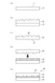
- Step a A substrate 10 made of SiC having a predetermined flat surface 11 is prepared.
- Step b Diamond is heteroepitaxially grown from a source gas by thermal CVD to form a diamond film 20 on the flat surface 11 of the substrate 10.
- Step c After the film formation, the substrate 10 or its surface is melted by dry etching using a fluorine-based etching gas, and the diamond film 20 is taken out from the substrate 10.
- Adhesive 40 (adhesive layer) is applied to the base material 30 constituting the structure of the sliding member 50, the diamond film 20 is turned upside down, and the film formation surface 22 that was the upper surface at the time of film formation is formed. It is pressed and attached to the lower side, that is, the base material 30 side.
- Step e The sliding member 50 in which the sliding surface 21 (transfer surface 21) is formed by transfer can be obtained.
- the flat surface 11 is a smooth surface, and the smoothness level is Rmax (maximum height), Rz (ten-point average roughness), Ra (centerline average roughness) according to JIS 0601-1976. ) And the like.
- the predetermined flat surface 11 only needs to have a smooth surface.
- a surface having an Ra of 1.6a or less is defined as a smooth surface.
- step c since the diamond film 20 taken out from the substrate 10 has a transfer surface 21 which is a lower surface of the diamond film 20 transferred from the flat surface 11 of the substrate 10, Ra of the surface is substantially equal to Ra of the flat surface 11. Equally 1.6a.
- the diamond film 20 has a film surface 22 which is the upper surface thereof, which is significantly rougher than the transfer surface 21.
- the film formation surface 22 is extremely drawn on the surface.
- the means for taking out the diamond film 20 from the substrate 10 may be a means other than dry etching, for example, a means for physically peeling. In the case of dry etching or wet etching, it is preferable to use an etching agent that dissolves only the substrate 10 without dissolving the diamond film 20.
- the adhesive 40 used in step d has a Young's modulus higher than that of the base material 30 and the diamond film 20 in a state where the base material 30 and the diamond film 20 are bonded and fixed in step e (the adhesive is cured). Use a small one.
- the structure is a member that constitutes a mechanical element of a machine / equipment such as a housing or a rotary shaft, and the base material 30 constitutes a part of the structure.
- the sliding surface 21 of the diamond film 20 is the transfer surface 21, the surface roughness of the sliding surface 21 and the accuracy of the surface shape are high. For this reason, even the diamond film 20 mainly composed of diamond that is hard and difficult to process has high surface roughness and surface shape accuracy.
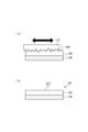
- the film-forming surface 22 on the opposite side of the sliding surface 21 is rougher than the sliding surface 21. That is, since the smooth surface is the sliding surface 21, processing such as lapping can be unnecessary or reduced. That is, as shown in FIG. 2, the film-forming surface 122 of the diamond film 120 formed on the substrate 130 as a base material, which is necessary for the conventional sliding member 150, is used for polishing diamond. The processing for obtaining the flat sliding surface 122 ′ by co-grinding and polishing with the film 140 can be unnecessary or reduced.
- the diamond film 20 is fixed to the base material 30 by adhesion of the adhesive 40, any material that can be bonded by the adhesive 40 can be fixed, and the diamond film 20 is fixed to the base material 30. Wide selection of materials. That is, the diamond film 20 can be fixed regardless of the material of the substrate 10 on which the diamond film 20 is formed.
- the diamond film 20 bonded to the base material 30 may be a single member or a plurality of members in the surface direction of the base material 30. By using a plurality of members, a sliding surface having a large area can be easily formed.
- the roughness of the film formation surface 22 on the adhesive 40 side is rougher than the surface roughness of the sliding surface 21, and the film formation surface 22 has a large surface area in contact with the adhesive 40. Can be firmly fixed to the substrate 30. Further, since the roughness of the film forming surface 22 on the adhesive 40 side may be rough, the film forming speed can be increased. On the other hand, since the sliding surface 21 is the transfer surface 21, the accuracy of the surface roughness and the surface shape is high.
- the adhesive 40 has a Young's modulus smaller than that of the base material 30 and the diamond film 20 in a state where the base material 30 and the diamond film 20 are bonded and fixed, an intermediate layer by the adhesive 40 is so-called during sliding. Functions as a cushioning material. That is, even if the base material 30 is deformed by thermal expansion, the base material 30 is buffered by the intermediate layer of the adhesive, and the influence of the force acting between the base material 30 and the diamond film 20 can be reduced.
- the second embodiment is mainly different from the first embodiment in that a concave portion is provided on the sliding surface 21.
- the same structure as Example 1 and the overlapping structure are abbreviate
- the substrate 10 has a trapezoidal convex portion 13 that protrudes upward from the flat surface 11 of the base portion 12.
- a concave portion 24 is formed along the shape of the convex portion 13 on the transfer surface 21 (sliding surface 21) side of the diamond film 20.
- the depth of the recess 24 is preferably shallower (shorter) than the thickness of the base 23 of the diamond film 20 because the mechanical strength of the diamond film 20 can be secured.
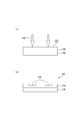
- the convex portion 13 is formed on the substrate 10, and the convex portion 13 is transferred to the diamond film 20 to form the concave portion 24, so that the concave portion 24 having a desired shape can be easily formed. it can. That is, as shown in FIG. 4, in order to obtain the recess 124, the film formation surface 122 of the diamond film 120 formed on the substrate 130 as the base material, which is necessary in the conventional sliding member 150, is obtained. No processing by the laser 160 is required.
- the convex portion 13 is formed on the substrate 10 and the concave portion 24 is transferred to the diamond film 20 has been described, but the concave portion is formed on the substrate 10 and the convex portion is formed on the diamond film 20.
- a specific function may be given to the sliding surface 21. Furthermore, you may provide both the convex part and recessed part which provide a specific function to a sliding surface.
- the sliding member according to the third embodiment will be described with reference to FIG.
- the shape of the base material 30 on which the diamond film 20 is provided is mainly different from the first embodiment.
- the same structure as Example 1 and the overlapping structure are abbreviate
- the base material 30 has a substantially inverted J-shaped cross section in which the long side portion 31 and the short side portion 32 are connected, and the diamond film 20 extends along the upper surface of the long side portion 31. Mounting is fixed.
- the diamond film 20 since the diamond film 20 is attached and fixed to the base material 30 with the adhesive 40, the diamond film 20 can be disposed also in the recess of the space formed by the long side portion 31 and the short side portion 32. . That is, when the diamond film 20 is directly formed on the upper surface of the long side portion 31, it is blocked by the short side portion 32 and cannot be formed in the region A, but the diamond film 20 is attached to the base material 30 with the adhesive 40. Therefore, the diamond film 20 can be provided also in the region A, and the degree of freedom of the shape of the base material 30 is high.
- an example in which the surface of the part to which the diamond film 20 of the base material 30 is attached is flat, but the surface may be curved.
- the planar diamond film 20 when the planar diamond film 20 is attached to the base material 30, it may be attached by being deformed along the surface of the base material 30, or the curved substrate 10 having a shape along the surface of the base material 30.
- a curved diamond film 20 obtained by forming a film on the substrate 30 may be attached and fixed to the surface of the substrate 30.
- the diamond film 20 since the diamond film 20 has a planar shape, the production of the diamond film 20 is simple.
- the diamond film 20 is not deformed, and is attached to the substrate 30 and fixed. It is preferable because internal stress is not substantially generated in the film 20.
Landscapes
- Chemical & Material Sciences (AREA)
- Organic Chemistry (AREA)
- Engineering & Computer Science (AREA)
- Materials Engineering (AREA)
- Metallurgy (AREA)
- Inorganic Chemistry (AREA)
- Mechanical Engineering (AREA)
- General Engineering & Computer Science (AREA)
- Chemical Kinetics & Catalysis (AREA)
- General Chemical & Material Sciences (AREA)
- General Life Sciences & Earth Sciences (AREA)
- Life Sciences & Earth Sciences (AREA)
- Geology (AREA)
- Crystallography & Structural Chemistry (AREA)
- Sliding-Contact Bearings (AREA)
- Chemical Vapour Deposition (AREA)
Abstract
Description
また、硬質炭素素材を主成分とするしゅう動膜を種々の基材に設けることができるしゅう動部材及びその製造方法を提供することを目的とする。
滑らかな転写面を有し、当該転写面がしゅう動面である硬質炭素素材を主成分とする。
このことから、しゅう動面が転写面であるため、硬質炭素素材を主成分とするしゅう動膜のしゅう動面の表面粗さ、表面形状の精度が高い。
このことから、硬く加工のしにくいダイヤモンドであっても、しゅう動面の表面粗さ、表面形状の精度が高い。
このことから、滑らかな側の面をしゅう動面としたため、ラッピング等の加工を不要乃至少なくすることができる。
滑らかな表面の基板上に硬質炭素素材を主成分とするしゅう動膜を成膜する成膜工程と、
前記成膜工程で成膜されたしゅう動膜を前記基板から取り出す取出工程と
を含む。
このことから、基板の滑らかな表面がしゅう動膜に転写されるため、転写されたしゅう動面の表面粗さ、表面形状の精度が高い。
このことから、基板の表面が正確にしゅう動膜に転写される。
このことから、しゅう動膜に、凸部や凹部に対応する凹部や凸部を簡単に形成することができる。
このことから、硬く加工のしにくいダイヤモンドであっても、しゅう動面の表面粗さ、表面形状の精度が高い。
このことから、しゅう動膜の基板とは反対側の面は粗くてもよいため、成膜の速度を高められる。
基材と、
しゅう動面を有し硬質炭素素材を主成分とするしゅう動膜と
前記基材に前記しゅう動膜を接着する接着層と
を備えている。
このことから、接着層の接着によりしゅう動膜は基材に固定されているため、しゅう動膜が固定されている基材の材質の選択の幅が広い。
このことから、ダイヤモンドが成膜される基板の材質に関係なくしゅう動膜を固定できるため、基材の材質の選択の幅が広い。
このことから、しゅう動膜は接着層と接触する表面積が広いため、しゅう動膜を基材に強固に固定することができる。
このことから、しゅう動面が転写面であるため、しゅう動面の表面粗さ、表面形状の精度が高い。
このことから、しゅう動時に接着層がいわゆる緩衝材として機能し、基材としゅう動膜との間に作用する力の影響を小さくすることができる。
成膜工程で成膜された硬質炭素素材を主成分とするしゅう動膜を前記基板から取り出す取出工程と、
前記取出工程で取り出した前記しゅう動膜を基材に接着する接着工程と
を含む。
これによれば、基板にダイヤモンド膜を接着するため、ダイヤモンド膜を固定する基材の材質の選択の幅が広い。
このことから、基板の滑らかな表面がしゅう動膜に転写されるため、転写されたしゅう動面の表面粗さ、表面形状の精度が高い。
このことから、基板の表面が正確にしゅう動膜に転写される。
このことから、しゅう動膜に、凸部や凹部に対応する凹部や凸部を簡単に形成することができる。
このことから、硬く加工のしにくいダイヤモンドであっても、しゅう動面の表面粗さ、表面形状の精度が高い。
このことから、しゅう動膜の基板とは反対側の面は粗くてもよいため、成膜の速度を高められる。
なお、基板として単結晶ダイヤモンドを用い、当該基板上にダイヤモンドをホモエピタキシャル成長させてもよい。
(ステップa)所定の平坦面11を有するSiCからなる基板10を準備する。
(ステップb)熱CVDにより原料ガスからダイヤモンドをヘテロエピタキシャル成長させてダイヤモンド膜20を基板10の平坦面11上に成膜する。
(ステップc)成膜後、フッ素系のエッチングガスを用いてドライエッチングにより、基板10又はその表面を溶かし、基板10からダイヤモンド膜20を取り出す。
(ステップd)しゅう動部材50の構造体を構成する基材30に接着剤40(接着層)を塗布し、ダイヤモンド膜20を上下反転させて、成膜時に上面であった成膜面22を下側すなわち基材30側に押圧して取り付ける。
(ステップe)しゅう動面21(転写面21)が転写により形成されたしゅう動部材50を得ることができる。
11 平坦面
13 凸部
20 ダイヤモンド膜(しゅう動膜)
21 転写面、しゅう動面
22 成膜面
24 凹部
30 基材
40 接着剤(接着層)
50 しゅう動部材
Claims (19)
- 滑らかな転写面を有し、当該転写面がしゅう動面である硬質炭素素材を主成分とすることを特徴とするしゅう動膜。
- 前記硬質炭素素材はダイヤモンドであることを特徴とする請求項1に記載のしゅう動膜。
- 使用前において、しゅう動面の粗さよりも当該しゅう動面とは反対側の面の粗さが粗いことを特徴とする請求項1又は2に記載のしゅう動膜。
- 滑らかな表面の基板上に硬質炭素素材を主成分とするしゅう動膜を成膜する成膜工程と、
前記成膜工程で成膜されたしゅう動膜を前記基板から取り出す取出工程と、
を含むことを特徴とするしゅう動膜の製造方法。 - 前記取出工程では前記基板を溶かして前記しゅう動膜を取り出すことを特徴とする請求項4に記載のしゅう動膜の製造方法。
- 前記基板には凸部又は凹部の少なくともいずれか一方が形成されていることを特徴とする請求項4項又は5に記載のしゅう動膜の製造方法。
- 前記硬質炭素素材はダイヤモンドであることを特徴とする請求項4乃至6のいずれかに記載のしゅう動膜の製造方法。
- 前記基板の表面の粗さよりも、前記基板とは反対側のしゅう動膜の面の粗さは粗いことを特徴とする請求項4項乃至7のいずれかに記載のしゅう動膜の製造方法。
- 基材と、
しゅう動面を有し硬質炭素素材を主成分とするしゅう動膜と、
前記基材に前記しゅう動膜を接着する接着層と、
を備えていることを特徴とするしゅう動部材。 - 前記硬質炭素素材はダイヤモンドであることを特徴とする請求項9に記載のしゅう動部材。
- 前記しゅう動膜は、接着層側の表面粗さがしゅう動面側の表面粗よりも粗いことを特徴とする請求項9又は10に記載のしゅう動部材。
- しゅう動面は転写面であることを特徴とする請求項9乃至11のいずれかに記載のしゅう動部材。
- 前記接着層は、前記基材と前記しゅう動膜とを接着し固定した状態において、前記基材及び前記しゅう動膜よりもヤング率が小さいことを特徴とする請求項9乃至12のいずれかに記載のしゅう動部材。
- 成膜工程で成膜された硬質炭素素材を主成分とするしゅう動膜を前記基板から取り出す取出工程と、
前記取出工程で取り出した前記しゅう動膜を基材に接着する接着工程と、
を含むことを特徴とするしゅう動部材の製造方法。 - 前記成膜工程は、滑らかな表面の基板上に硬質炭素素材を主成分とするしゅう動膜を成膜することを特徴とする請求項14に記載のしゅう動部材の製造方法。
- 前記取出工程では前記基板を溶かして前記しゅう動膜を取り出すことを特徴とする請求項14又は15に記載のしゅう動部材の製造方法。
- 前記基板には凸部又は凹部の少なくともいずれか一方が形成されていることを特徴とする請求項14乃至16のいずれかに記載のしゅう動部材の製造方法。
- 前記硬質炭素素材はダイヤモンドであることを特徴とする請求項14乃至17のいずれかに記載のしゅう動部材の製造方法。
- 前記基板の表面の粗さよりも、前記基板とは反対側のしゅう動膜の面の粗さは粗いことを特徴とする請求項14乃至18のいずれかに記載のしゅう動部材の製造方法。
Priority Applications (4)
| Application Number | Priority Date | Filing Date | Title |
|---|---|---|---|
| JP2017519160A JP6830743B2 (ja) | 2015-05-15 | 2016-05-12 | シール用しゅう動部材及びその製造方法 |
| CN201680023035.4A CN107532295A (zh) | 2015-05-15 | 2016-05-12 | 滑动膜及其制造方法以及滑动部件及其制造方法 |
| US15/568,179 US20180142347A1 (en) | 2015-05-15 | 2016-05-12 | Sliding film, method of producing same, sliding member, and method of producing same |
| EP16796384.2A EP3296427A4 (en) | 2015-05-15 | 2016-05-12 | SLIDING FILM, METHOD FOR THE PRODUCTION THEREOF, LID ELEMENT AND METHOD FOR THE PRODUCTION THEREOF |
Applications Claiming Priority (2)
| Application Number | Priority Date | Filing Date | Title |
|---|---|---|---|
| JP2015099902 | 2015-05-15 | ||
| JP2015-099902 | 2015-05-15 |
Publications (1)
| Publication Number | Publication Date |
|---|---|
| WO2016185991A1 true WO2016185991A1 (ja) | 2016-11-24 |
Family
ID=57319983
Family Applications (1)
| Application Number | Title | Priority Date | Filing Date |
|---|---|---|---|
| PCT/JP2016/064093 Ceased WO2016185991A1 (ja) | 2015-05-15 | 2016-05-12 | しゅう動膜及びその製造方法並びにしゅう動部材及びその製造方法 |
Country Status (5)
| Country | Link |
|---|---|
| US (1) | US20180142347A1 (ja) |
| EP (1) | EP3296427A4 (ja) |
| JP (1) | JP6830743B2 (ja) |
| CN (1) | CN107532295A (ja) |
| WO (1) | WO2016185991A1 (ja) |
Cited By (1)
| Publication number | Priority date | Publication date | Assignee | Title |
|---|---|---|---|---|
| WO2020039775A1 (ja) * | 2018-08-24 | 2020-02-27 | 日本電産コパル電子株式会社 | 空気動圧軸受 |
Families Citing this family (2)
| Publication number | Priority date | Publication date | Assignee | Title |
|---|---|---|---|---|
| JP7445314B2 (ja) * | 2019-04-26 | 2024-03-07 | 株式会社フジキン | ダイヤフラム、バルブ、およびダイヤフラムの製造方法 |
| JP7032469B2 (ja) * | 2020-03-26 | 2022-03-08 | 大同メタル工業株式会社 | 摺動部材 |
Citations (3)
| Publication number | Priority date | Publication date | Assignee | Title |
|---|---|---|---|---|
| JPH10263966A (ja) * | 1997-03-24 | 1998-10-06 | Toyoda Mach Works Ltd | 気相合成された膜を備えた工作物支持具及びその製造方法 |
| JP2001203155A (ja) * | 1999-11-10 | 2001-07-27 | Shin Etsu Chem Co Ltd | リソグラフィ用ダイヤモンド膜の製造方法 |
| JP2005060179A (ja) * | 2003-08-15 | 2005-03-10 | Ind Technol Res Inst | 高表面細かさを有するダイヤモンド膜構造製造方法 |
Family Cites Families (9)
| Publication number | Priority date | Publication date | Assignee | Title |
|---|---|---|---|---|
| JPH07172989A (ja) * | 1993-12-20 | 1995-07-11 | Matsushita Electric Ind Co Ltd | ダイヤモンド基体の製造方法 |
| FR2738832B1 (fr) * | 1995-09-18 | 1997-12-12 | Suisse Electronique Microtech | Procede d'obtention d'une couche de diamant sur un support en matiere plastique et produit ainsi obtenu |
| CA2202225C (en) * | 1996-05-16 | 2000-12-26 | James M. Olson | Synthetic diamond wear component and method |
| JP2002323045A (ja) * | 2001-04-23 | 2002-11-08 | Ricoh Opt Ind Co Ltd | 摺動部材及びその製造方法 |
| EP1479946B1 (en) * | 2003-05-23 | 2012-12-19 | Nissan Motor Co., Ltd. | Piston for internal combustion engine |
| DE102008037871A1 (de) * | 2008-08-15 | 2010-02-25 | Amg Coating Technologies Gmbh | Gleitelement mit Mehrfachschicht |
| WO2010100261A1 (de) * | 2009-03-06 | 2010-09-10 | Friedrich-Alexander-Universität Erlangen-Nürnberg | Selbsttragende cvd-diamantfolie und verfahren zur herstellung einer selbsttragenden cvd-diamantfolie |
| DE202010011173U1 (de) * | 2010-08-09 | 2011-12-22 | Eagleburgmann Germany Gmbh & Co. Kg | Gleitring mit verbesserten Einlaufeigenschaften |
| US20140079910A1 (en) * | 2011-05-10 | 2014-03-20 | Kazuo Tsugawa | Carbon film laminate, method of manufacturing said laminate, and lubricant using said laminate |
-
2016
- 2016-05-12 JP JP2017519160A patent/JP6830743B2/ja active Active
- 2016-05-12 WO PCT/JP2016/064093 patent/WO2016185991A1/ja not_active Ceased
- 2016-05-12 EP EP16796384.2A patent/EP3296427A4/en not_active Withdrawn
- 2016-05-12 US US15/568,179 patent/US20180142347A1/en not_active Abandoned
- 2016-05-12 CN CN201680023035.4A patent/CN107532295A/zh active Pending
Patent Citations (3)
| Publication number | Priority date | Publication date | Assignee | Title |
|---|---|---|---|---|
| JPH10263966A (ja) * | 1997-03-24 | 1998-10-06 | Toyoda Mach Works Ltd | 気相合成された膜を備えた工作物支持具及びその製造方法 |
| JP2001203155A (ja) * | 1999-11-10 | 2001-07-27 | Shin Etsu Chem Co Ltd | リソグラフィ用ダイヤモンド膜の製造方法 |
| JP2005060179A (ja) * | 2003-08-15 | 2005-03-10 | Ind Technol Res Inst | 高表面細かさを有するダイヤモンド膜構造製造方法 |
Non-Patent Citations (1)
| Title |
|---|
| See also references of EP3296427A4 * |
Cited By (1)
| Publication number | Priority date | Publication date | Assignee | Title |
|---|---|---|---|---|
| WO2020039775A1 (ja) * | 2018-08-24 | 2020-02-27 | 日本電産コパル電子株式会社 | 空気動圧軸受 |
Also Published As
| Publication number | Publication date |
|---|---|
| CN107532295A (zh) | 2018-01-02 |
| JPWO2016185991A1 (ja) | 2018-03-01 |
| EP3296427A4 (en) | 2019-02-20 |
| JP6830743B2 (ja) | 2021-02-17 |
| EP3296427A1 (en) | 2018-03-21 |
| US20180142347A1 (en) | 2018-05-24 |
Similar Documents
| Publication | Publication Date | Title |
|---|---|---|
| TWI389165B (zh) | 鑽石上半導體裝置及其形成方法 | |
| TWI390619B (zh) | 同時研磨複數個半導體晶圓之方法 | |
| CN201168928Y (zh) | 一种用于衬底化学机械抛光装置的载具头及其柔性膜 | |
| JP5207909B2 (ja) | キャリア、キャリアを被覆する方法並びに半導体ウェハの両面を同時に材料除去する加工方法 | |
| JP6085371B2 (ja) | 半導体デバイス用基板 | |
| JP4395495B2 (ja) | 半導体ウェーハを加工する方法、キャリア及び半導体ウェーハ | |
| Li et al. | Ultrasonic vibration mill-grinding of single-crystal silicon carbide for pressure sensor diaphragms | |
| US20140154956A1 (en) | Pad Conditioning and Wafer Retaining Ring and Manufacturing Method Thereof | |
| JPWO2016185991A1 (ja) | しゅう動膜及びその製造方法並びにしゅう動部材及びその製造方法 | |
| JP5260309B2 (ja) | 凹形非研磨中間表面を有するセラミック切削インサート及びそのような切削インサートの製造方法 | |
| KR20200003194A (ko) | 서셉터, 애피택셜 기판의 제조 방법, 및 애피택셜 기판 | |
| JP2009111423A5 (ja) | GaN結晶基板およびその製造方法 | |
| TW201513194A (zh) | 可翻新之經塗覆之化學機械硏磨調節器及其製造方法以及用於化學機械硏磨中的整合系統 | |
| TW201935548A (zh) | 用於拋光半導體晶圓的方法 | |
| JP3998603B2 (ja) | ガラスプレス用モールドの作製方法 | |
| JP6825733B1 (ja) | 半導体ウェーハの製造方法 | |
| CN100468645C (zh) | 半导体晶片的制造方法 | |
| CN105571749A (zh) | 压力传感器形成方法 | |
| EP1300945A3 (en) | Diamond substrate for surface acoustic wave device, and surface acoustic wave device | |
| WO2008058270A3 (en) | A susceptor and method of forming a led device using such susceptor | |
| JP6256576B1 (ja) | エピタキシャルウェーハ及びその製造方法 | |
| US20060243983A1 (en) | Diamond substrate and method for fabricating the same | |
| Yamaguchi et al. | Development of diamond-like carbon fibre wheel | |
| US20090036030A1 (en) | Polishing head and chemical mechanical polishing process using the same | |
| US20160099320A1 (en) | Semiconductor composite film with heterojunction and manufacturing method thereof |
Legal Events
| Date | Code | Title | Description |
|---|---|---|---|
| 121 | Ep: the epo has been informed by wipo that ep was designated in this application |
Ref document number: 16796384 Country of ref document: EP Kind code of ref document: A1 |
|
| ENP | Entry into the national phase |
Ref document number: 2017519160 Country of ref document: JP Kind code of ref document: A |
|
| WWE | Wipo information: entry into national phase |
Ref document number: 15568179 Country of ref document: US |
|
| NENP | Non-entry into the national phase |
Ref country code: DE |
|
| WWE | Wipo information: entry into national phase |
Ref document number: 2016796384 Country of ref document: EP |