WO2016186149A1 - ステアリング装置 - Google Patents
ステアリング装置 Download PDFInfo
- Publication number
- WO2016186149A1 WO2016186149A1 PCT/JP2016/064801 JP2016064801W WO2016186149A1 WO 2016186149 A1 WO2016186149 A1 WO 2016186149A1 JP 2016064801 W JP2016064801 W JP 2016064801W WO 2016186149 A1 WO2016186149 A1 WO 2016186149A1
- Authority
- WO
- WIPO (PCT)
- Prior art keywords
- column
- outer column
- steering
- portions
- width direction
- Prior art date
- Legal status (The legal status is an assumption and is not a legal conclusion. Google has not performed a legal analysis and makes no representation as to the accuracy of the status listed.)
- Ceased
Links
Images


Classifications
-
- B—PERFORMING OPERATIONS; TRANSPORTING
- B62—LAND VEHICLES FOR TRAVELLING OTHERWISE THAN ON RAILS
- B62D—MOTOR VEHICLES; TRAILERS
- B62D1/00—Steering controls, i.e. means for initiating a change of direction of the vehicle
- B62D1/02—Steering controls, i.e. means for initiating a change of direction of the vehicle vehicle-mounted
- B62D1/16—Steering columns
- B62D1/18—Steering columns yieldable or adjustable, e.g. tiltable
- B62D1/184—Mechanisms for locking columns at selected positions
-
- B—PERFORMING OPERATIONS; TRANSPORTING
- B62—LAND VEHICLES FOR TRAVELLING OTHERWISE THAN ON RAILS
- B62D—MOTOR VEHICLES; TRAILERS
- B62D1/00—Steering controls, i.e. means for initiating a change of direction of the vehicle
- B62D1/02—Steering controls, i.e. means for initiating a change of direction of the vehicle vehicle-mounted
- B62D1/16—Steering columns
- B62D1/18—Steering columns yieldable or adjustable, e.g. tiltable
- B62D1/185—Steering columns yieldable or adjustable, e.g. tiltable adjustable by axial displacement, e.g. telescopically
-
- B—PERFORMING OPERATIONS; TRANSPORTING
- B62—LAND VEHICLES FOR TRAVELLING OTHERWISE THAN ON RAILS
- B62D—MOTOR VEHICLES; TRAILERS
- B62D1/00—Steering controls, i.e. means for initiating a change of direction of the vehicle
- B62D1/02—Steering controls, i.e. means for initiating a change of direction of the vehicle vehicle-mounted
- B62D1/16—Steering columns
- B62D1/18—Steering columns yieldable or adjustable, e.g. tiltable
- B62D1/187—Steering columns yieldable or adjustable, e.g. tiltable with tilt adjustment; with tilt and axial adjustment
Definitions
- the present invention relates to a steering device with a position adjustment mechanism that enables the position of a steering wheel to be adjusted according to the physique and driving posture of a driver.
- This application includes Japanese Patent Application No. 2015-102171 filed on May 19, 2015, Japanese Patent Application No. 2015-203675 filed on October 15, 2015, and Japanese Patent Application filed on October 21, 2015. Claims priority based on No. 2015-207039, the contents of which are incorporated herein.
- the steering device is configured to transmit the movement of the steering wheel 1 to the steering gear unit via the steering shaft 2 and to give a steering angle to the left and right steering wheels 3.
- the steering gear unit is configured to displace (push and pull) the tie rod 6 based on the rotation of the steering shaft 2.
- a steering device that can adjust the position of the steering wheel 1 in accordance with the physique and driving posture of the driver has been known.
- a steering device with a position adjustment mechanism is required to be highly stable while being required to be compact and lightweight.
- An object of the aspect of the present invention is to provide a steering apparatus with a position adjustment mechanism having high stability.
- a steering apparatus includes an outer column, a steering column having an inner column partially surrounded by the outer column, a support bracket attached to a vehicle body and supporting the steering column, and the support And a tightening mechanism having a first state in which the steering column is tightened via a bracket and a second state in which the tightening is released.
- the outer column is spaced apart from each other in a first direction intersecting the axial direction, and the first surface and the second surface pressed by the support bracket in the first state, and the first surface and the second surface And the clamp portion having a third surface which is provided independently from the first surface and is pressed by the support bracket in the first state.
- a steering apparatus includes a steering column formed by fitting a front portion of an outer column disposed rearward to a rear portion of an inner column disposed forward to enable relative displacement in the axial direction.
- a pair of support plate portions sandwiching the front portion of the outer column from both sides in the width direction, a support bracket supported by the vehicle body, a first through hole formed in the front portion of the outer column, and the support plates Adjustment rods respectively inserted in the width direction are provided in the second through holes formed in the respective portions.
- a slit extending at least in the axial direction of the outer column is formed in the front portion of the outer column.
- the outer column is adjacent to the slit in the circumferential direction, and bends when the distance between the inner side surfaces of the support plate portions is reduced at both side portions in the width direction of the outer column, and the outer peripheral surface of the inner column is A pair of clamp portions that are elastically sandwiched are provided.
- a pair of working surfaces that are spaced apart from each other on both sides in the width direction of the outer column in the vertical direction with the clamp portion interposed therebetween, and that transmit torque acting on the outer column to the inner side surface of each support plate portion Is provided.
- a steering apparatus with a position adjustment mechanism having high stability is provided.
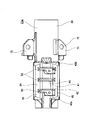
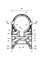
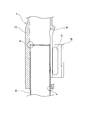
- FIG. 2 is an enlarged cross-sectional view taken along the line AOOA in FIG. 1.
- the perspective view of a steering column The perspective view which looked at the steering column from another angle.
- the side view of a steering column The end view which looked at the steering column from the left side of FIG.
- the end view which looked at the steering column from the right side of FIG. BB expanded sectional view of FIG. CC sectional drawing of FIG. DD sectional drawing of FIG.
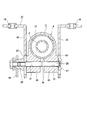
- FIG. 23 is a cross-sectional view taken along the line HH in FIG. 22.
- the perspective view which shows a sliding member.
- the side view of a steering column which shows the 2nd example of embodiment of this invention.
- the side view of a steering device which shows the 3rd example of embodiment of this invention.
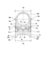
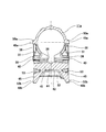
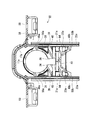
- FIG. 29 is an enlarged cross-sectional view taken along line AOOA in FIG.
- the perspective view which shows the state which looked at the outer column and the upper bracket from back and the lower side.
- the perspective view which shows the state which looked at the outer column and the upper bracket from back and the upper side.
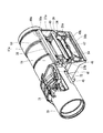
- the perspective view which shows the state which looked at the outer column from back and the upper side.
- the side view which shows the state which looked at the outer column from the width direction one side.
- the bottom view which shows the state seen from the downward direction of FIG. BB sectional drawing of FIG. CC sectional drawing of FIG. DD sectional drawing of FIG.
- the perspective view of a steering column which shows the 4th example of embodiment of this invention.
- the side view of an outer column The perspective view of a steering column which shows the 5th example of embodiment of this invention.
- Sectional drawing of an outer column Sectional drawing of an outer column and an upper bracket.
- It is a conceptual diagram which shows the correlation of lever operating force and holding force, (A) shows the state in which the outer column is provided with the limiting surface, and (B) shows the state in which the outer column is not provided with the limiting surface.
- 1 is a schematic perspective view showing an example of a steering device mounted on a vehicle.
- the schematic side view which shows an example of the steering device of a conventional structure.
- JJ sectional drawing of FIG. The fragmentary sectional view shown in order to demonstrate the problem of the steering device of the conventional structure.
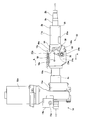
- the steering device of this example includes a steering wheel 1, a steering shaft 2a, a steering column 4a, a tightening mechanism 80, a steering force assisting device (assist device, electric power steering device) 5a, and a steering gear unit 7. Prepare.
- the steering shaft 2a has an inner shaft 8a that is disposed relatively forward and an outer shaft 9a that is disposed relatively rearward.
- the “front-rear direction” corresponds to the front-rear direction of the vehicle body on which the steering device is installed.
- the steering column 4a is supported by the vehicle body 15a.
- the steering column 4a has a cylindrical shape.
- the steering column 4a can have a shape other than a cylindrical shape.
- the steering column 4a includes at least a part of the steering shaft 2a.
- a steering shaft 2a is inserted inside the steering column 4a.
- a steering shaft 2a is rotatably supported on the inner diameter side of the steering column 4a via a plurality of rolling bearings (not shown).
- a part of the steering shaft 2a is disposed so as to protrude rearward from the rear end opening of the steering column 4a.
- a steering wheel 1 is fixed to the rear end portion of the steering shaft 2a.
- an electric motor 32a (assist device 5a) serving as a power source for applying auxiliary force is disposed.
- the electric motor 32a is supported by a gear housing 12a fixed to the front end portion of the steering column 4a.
- a part of the inner shaft 8a is inserted into the gear housing 12a.
- a front end portion of the inner shaft 8a is coupled to a predetermined axis in the steering force assisting device 5a.
- a shaft connected to a predetermined shaft via a torsion bar or the like protrudes from the front end surface of the gear housing 12.
- the output torque (auxiliary force) of the electric motor 32a is applied to the steering shaft 2a through a reduction gear provided in the gear housing 12a.
- the gear housing 12a is supported and fixed to the vehicle body 15a via the lower bracket 14a.
- the steering device adjusts the tilt mechanism (an example of a position adjustment mechanism) for adjusting the vertical position of the steering wheel 1 and the front-rear position of the steering wheel 1 according to the physique and driving posture of the driver.
- a telescopic mechanism (an example of a position adjusting mechanism).
- the steering device may include one of a tilt mechanism and a telescopic mechanism and may not include the other.
- the inner shaft 8a and the outer shaft 9a are combined so that rotational force can be transmitted and relative displacement in the axial direction can be achieved.
- the steering shaft 2a has a spline engagement structure.
- the front and rear positions of the steering wheel 1 can be adjusted by the relative displacement of the inner shaft 8a and the outer shaft 9a in the axial direction (the steering shaft 2a expands and contracts). Even when a strong impact is received, the total length of the steering shaft 2a can be reduced by the relative displacement.
- the steering column 4a has an inner column 10a that is disposed relatively forward and an outer column 11a that is disposed relatively rearward.
- a part of the inner column 10a is inserted into the outer column 11a, and the inner column 10a is disposed so as to be movable relative to the outer column 11a in the axial direction.
- a part of the inner column 10a is surrounded by the outer column 9a.
- the steering column 4a is supported on the vehicle body 15a by an upper bracket (support bracket) 17a.
- the outer column 11a is supported so as to be movable in the front-rear direction with respect to the upper bracket 17a.
- the support bracket 17a is supported by the vehicle body 15a via the locking capsule 18a so that the support bracket 17a can be detached (dropped) when receiving a strong impact.
- the “axial direction” corresponds to the axial direction of the steering shaft 2a or the axial direction of the outer column 11a.
- one end of the inner column 10a is supported by the vehicle body 15a by the lower bracket 14a via the gear housing 12a.
- the lower bracket 14a supports the gear housing 12a so as to be swingable around a tilt shaft 16a disposed along the width direction (substantially parallel to the width direction).
- the steering column 4a is supported with respect to the vehicle body 15a so as to be able to swing and displace around a tilt shaft 16a installed in the width direction.
- the outer column 11a is supported so as to be movable in the vertical direction with respect to the upper bracket 17a.
- the “width direction” corresponds to the width direction of the vehicle body on which the steering device is installed.
- the “vertical direction” corresponds to the vertical direction of the vehicle body on which the steering device is installed.
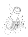
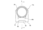
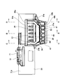
- the outer column 11a includes a light alloy frame (main body portion, sandwiched portion main body) 34 such as an aluminum alloy or a magnesium alloy, and a steel alloy cylindrical body (cylindrical shape) such as a carbon steel plate. Member) 35 is coupled in the axial direction.
- the outer column 11a is made of a light alloy such as an aluminum alloy or a magnesium alloy, and has a frame body (main body portion, sandwiched portion main body) 34 disposed in the front half portion and a cylinder disposed in the rear half portion.
- the body (cylindrical member) 35 may be arranged in the axial direction and integrally coupled.
- the outer column 11a can have other materials and / or other configurations.
- the frame 34 is supported so as to be movable in the front-rear direction and the up-down direction with respect to the upper bracket 17a.
- An axial slit 36 (first slit portion) extending in the axial direction is formed on the lower surface of the frame body 34.
- the front end portion of the axial slit 36 opens at the front end surface of the frame body 34.
- circumferential slits 37a and 37b extending in the circumferential direction are formed in the lower half of the frame 34 at the front end portion and the rear end portion, respectively.
- the front side circumferential slit 37a is formed in a state where the front end portion of the axial slit 36 intersects the circumferential direction.
- the rear side circumferential slit 37b is formed so as to intersect the rear end portion of the axial slit 36 in the circumferential direction.
- clamp portions 38 are formed that are surrounded on three sides by the axial slit 36, the circumferential slit 37a, and the circumferential slit 37b.
- the clamp portions 38 and 38 three sides are continuously opened by the axial slit 36 and the circumferential slits 37a and 37b, and the remaining one side is connected to the frame body 34. That is, at least two sides of the clamp unit 38 that are spaced apart from each other along the axial direction and one side in the first direction that intersects the axial direction (the first intersecting direction, generally the vertical direction in this example). A continuous non-fixed end is formed.
- the other one side in the first direction is a fixed end.
- the clamp part 38 has a cantilever structure having a fixed end extending in the axial direction.
- the clamp portion 38 has lower rigidity in at least the width direction than the other portions of the frame body 34, and can be elastically deformed in the width direction (the inner diameter can be elastically expanded or reduced).
- each clamp part 38 and 38 has a partial cylindrical surface-shaped inner peripheral surface.
- the clamp portions 38, 38 are provided adjacent to both sides in the circumferential direction of the axial slit 36.
- the clamp portions 38 and 38 have shapes extending in the axial direction and the circumferential direction (or the first direction).
- an intermediate portion in the first direction (generally in the vertical direction in this example) is in a state of projecting in the width direction, with a flat plate-like overhang plate portion (the overhang portion).
- the working surface 40 has a flat surface shape. Additionally and / or alternatively, the working surface 40 can have a shape other than flat.
- the first direction intersects the width direction of the vehicle body and is orthogonal to the axial direction.
- the first direction can correspond to the circumferential direction of the outer column 11a.
- the first direction can be a direction that intersects the axial direction differently from orthogonal.
- the second direction is a direction that intersects the axial direction and the first direction.
- the substantial tightening direction of the tightening mechanism 80 may coincide with the second direction.
- the second direction substantially coincides with the width direction of the vehicle body.
- the second direction can include directions other than the width direction of the vehicle body.
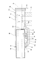
- the outer column 11a has a reinforcing bridge portion (reinforcing portion, reinforcing structure, reinforcing member) 41 that is bridged between both sides of the outer column 11a in the second direction (in this example, generally the width direction of the vehicle body).
- the reinforcing bridge portion 41 extends substantially continuously between both sides of the outer column 11a in the second direction, and is provided so as to physically connect both sides of the outer column 11a in the second direction.
- a reinforcing bridge portion 41 is provided at a lower portion of the frame body 34 so as to cover the clamp portions 38 and 38 from below.
- the reinforcing bridge portion 41 is provided integrally with the outer column 11a.
- the reinforcing bridge portion 41 includes a reinforcing plate portion 42 and a pair of connecting portions 43a and 43b.
- the shape of the reinforcing bridge portion 41 as viewed from the width direction has a substantially U shape (U shape).
- the reinforcing plate portion 42 is disposed below the clamp portions 38 and 38 and is provided in a state of extending in the width direction and the front-rear direction.
- the reinforcing plate portion 42 includes a flat plate portion (center flat plate portion) 44 disposed in the center in the width direction, and outer flat plate portions (downward extending portions) 45 and 45 disposed on both sides in the width direction and below the flat plate portion 44. And having a part.
- the flat plate portion 44 and the outer flat plate portion 45 are provided continuously via a stepped portion 46.
- the reinforcing bridge portion 41 has a crank-shaped cross section.
- the connecting portion 43a disposed relatively forward is provided so as to extend upward from both widthwise side portions (outer flat plate portions 45, 45) of the front end portion of the reinforcing plate portion 42.
- the connecting portion 43 a is a portion adjacent to the front side of the circumferential slit 37 a on the lower surface of the front end portion of the frame body 34, and is connected to both circumferential portions on both sides of the axial slit 36.
- the connecting portion 43 b disposed on the rear side is provided in a state of extending upward from the rear end portion of the reinforcing plate portion 42.
- the connecting portion 43 b is connected to a portion adjacent to the rear side of the rear end portion of the axial slit 36 on the lower surface of the rear end portion of the frame body 34.
- the reinforcing bridge portion 41 can have a different configuration from that described above.
- the outer column 11a has a high torsional rigidity by including the reinforcing bridge portion 41 as described above.
- interval (slit) 47 and 47 whose shape seen from the width direction (2nd direction) is substantially U shape (substantially U shape) is formed.
- the gaps 47, 47 are telescopic adjustment long holes (first through holes, axial slits, first slit portions) 21a, 21a extending at least in the axial direction (the axial direction of the outer column 11a, the axial direction of the steering shaft 2a).
- second slit portions 37a and 37b that are provided continuously to the long holes 21a and 21a and extend in a direction intersecting the long holes 21a and 21a.
- the clamp parts 38 and 38 are provided adjacent to the long holes 21a and 21a.
- the long holes 21 a and 21 a form a space that exists between the tip portions (lower end portions) of the clamp portions 38 and 38 and the upper surfaces of both sides of the flat plate portion 44 in the reinforcing plate portion 42 in the width direction.
- the adjustment rod 24a is inserted through the long holes 21a and 21a in the width direction (second direction).
- Roller travel grooves 48 and 48 are provided along the axial direction of the long holes 21a and 21a on both sides of the outer column 11a in the width direction.
- the concave grooves 48, 48 are provided in the width direction outer portions of the long holes 21a, 21a.
- the concave grooves 48, 48 are provided on the lower surfaces of the projecting plate portions 39, 39 provided on the clamp portions 38, 38, the upper surfaces of the outer flat plate portions 45, 45 of the reinforcing plate portion 42, and the clamp portions 38, 38.
- Three sides are surrounded by the width direction outer side surfaces (action surfaces 40, 40) of the tip and the width direction outer side surfaces of the step portions 46, 46 of the reinforcing plate 42.
- the concave grooves 48, 48 are the lower surface of the projecting plate portions 39, 39 as the first side wall surface, the upper surface of the outer flat plate portions 45, 45 as the second side wall surface, and the clamp portion as the first bottom surface. 38 and 38, and the outer surface of the level
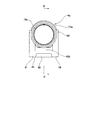
- the outer column 11a includes a working surface (first surface, first working surface, first contact surface, torque transmission surface) 49a and working surface (second surface, provided on each of two sides in the width direction. Second working surface, second contact surface, torque transmission surface) 49b.
- the working surface 49a and the working surface 49b are arranged to be separated from each other in a first direction (first crossing direction) that intersects the axial direction (the axial direction of the outer column 11a, the axial direction of the steering shaft 2a). .
- first crossing direction that intersects the axial direction (the axial direction of the outer column 11a, the axial direction of the steering shaft 2a).
- the clamp portion 38 and the action surface 40
- the action surface 49b is disposed between the action surface 49a and the action surface 49b.
- the adjustment rod 24a is disposed between the action surface 49a and the action surface 49b in the first direction
- the action surface 40 of the clamp portion 38 is between the action surface 49a and the adjustment rod 24a in the first direction.
- the axial slit 36 (the long hole 21a) is disposed between the working surface 49a and the working surface 49b in the first direction.
- torque force in the torsional direction acting on the outer column 11a can be transmitted to the inner side surfaces of the support plate portions 22a and 22a in the upper bracket 17a via the action surface 49a and the action surface 49b.
- the working surface 49a is disposed within the range of the outer shape of the inner column 10a in the first direction.
- the action surface 49b is disposed outside the range of the outer shape of the inner column 10a in the first direction. Furthermore, the action surface 49b is disposed outside the range of the outer shape of the cylindrical body 35 of the outer column 11a. Further, in the first direction, the working surface 49a is disposed relatively near the central axis of the inner column 10a, and the working surface 49b is disposed relatively far from the central axis of the inner column 10a.
- the outer column 11a protrudes outward in the width direction (second direction) at a portion located in the vicinity of the central axis of the outer column 11a in the first direction (or vertical direction).
- the protrusions 50 and 50 are provided.
- the protrusion 50 is provided extending in the axial direction of the outer column 11a.
- Action surfaces 49a and 49a are provided at the tips (width direction outer surfaces) of the protrusions 50 and 50, respectively.
- concave portions 51a and 51b that are recessed in the width direction are provided on both side portions (front and rear portions) of the protrusions 50 and 50 in the front-rear direction.
- the action surfaces 49a and 49a have such a shape that two linear portions extending in the axial direction are respectively connected at the front and rear end portions and the intermediate portion.
- the lower working surface 49b is provided at the tip (side surface in the width direction) of the reinforcing plate portion 42 (outer flat plate portions 45, 45).
- Each of the working surfaces 49a and 49b has a shape extending in the axial direction of the outer column 11a, and has a larger length in the axial direction than the clamp portion 38.
- each of the working surface 49a and the working surface 49b has a flat surface shape. Additionally and / or alternatively, the working surface 49a and the working surface 49b may have a shape other than a flat shape.
- the action surfaces 49a and 49b have higher rigidity in the width direction (second direction) than the clamp portions 38 and 38.
- the upper ends of the connecting portions 43a and 43b in the reinforcing bridge portion 41 are continuously connected to both end portions in the front-rear direction of the ridge portions 50 and 50, respectively.
- the front and rear ends of the working surfaces 49a and 49b are continuously connected to each other by continuous surfaces (for example, continuous flat surfaces) 52a and 52b extending in the vertical direction formed on the side surfaces in the width direction of the connecting portions 43a and 43b.
- the action surfaces 49a and 49b and the continuous surfaces 52a and 52b are formed in a substantially rectangular frame shape.
- the action surfaces 49a, 49b and the continuous surfaces 52a, 52b are located on the same virtual plane, and are located slightly outside in the width direction from the end surfaces in the width direction of the projecting plate portions 39, 39. ing.
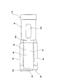
- a locking concave groove 53 extending in the circumferential direction is formed on the inner peripheral surface of the front end portion of the outer column 11a (frame body 34).
- the locking groove 53 and the axial slit 36 are made of a synthetic resin excellent in slidability such as polyamide resin, polyacetal resin, polytetrafluoroethylene resin, etc., and the whole is configured in a substantially C shape.
- a sliding member 54 is attached. Alternatively and / or additionally, the sliding member 54 can have other materials and / or other configurations.
- the sliding member 54 includes a sliding part main body 55 and a pair of supporting arm parts 56 and 56 each having a partially arc shape extending from both sides in the width direction of the sliding part main body 55.
- the sliding portion main body 55 is disposed in the axial slit 36. Support arm portions 56, 56 are arranged in the locking groove 53. In a state where the sliding member 54 is mounted, the upper surface of the sliding portion main body 55 is located on the same virtual cylindrical surface as the inner peripheral surface of the frame body 34 or slightly protrudes radially inward. Become.
- the sliding portion main body 55 is formed with a pair of concave portions 57 and 57 that are recessed in the axial direction.
- the two recesses 57 are arranged adjacent to each other in the width direction (circumferential direction).
- the sliding part main body 55 is set to have a relatively low rigidity in the vertical direction.
- the outer column 11a of this example a pair of sandwiched plate portions are provided integrally with the outer column 11a in a state where the axial slit 36 is sandwiched from both sides in the width direction, and the distal end portions of the both sandwiched plate portions are provided.
- the (lower end portions) are connected in the width direction (by the portion corresponding to the reinforcing plate portion 42).
- the outer side surfaces in the width direction of the both sandwiched plate portions are respectively substantially flat clamping surfaces.
- the upper bracket (support bracket) 17a is made of, for example, a metal plate having sufficient rigidity such as steel or aluminum alloy.
- the upper bracket 17a has a mounting plate portion 58 and a pair of support plate portions 22a and 22a.
- the mounting plate portion 58 has a substantially L-shaped cross section.
- the mounting plate 58 may have a different material and / or a different shape.
- the attachment plate portion 58 is normally supported with respect to the vehicle body 15a.
- the mounting plate portion 58 is configured so that the mounting plate portion 58 is detached forward based on an impact such as a secondary collision, and the outer column 11a is allowed to move forward.
- a pair of locking notches 59 and 59 are formed in the rear end edge of the mounting plate portion 58 in an open state.
- Locking capsules 18a and 18a fixed to the vehicle body 15a by locking members such as bolts or studs are locked to the locking notches 59 and 59.
- the locking capsules 18a and 18a are formed with locking grooves 60 and 60 for engaging the left and right side edges of the locking notches 59 and 59 on the left and right side surfaces of the locking capsules 18a and 18a, respectively.
- Through holes 61 and 61 are formed.
- the support plate portions 22 a and 22 a are provided so as to hang down from the mounting plate portion 55.
- the support plate portions 22a and 22a are provided so as to be parallel to each other with the front end portion (the frame body 34 and the reinforcing bridge portion 41) of the outer column 11a sandwiched from both sides in the width direction.
- the pair of support plate portions 22a and 22a are arranged on both sides of the outer column 11a in the width direction (second direction).
- Tilt adjusting long holes (second through holes) 23a and 23a extending at least in the vertical direction (first direction) are formed in the support plate portions 22a and 22a.
- the long holes 23a and 23a are provided at positions facing each other in the width direction (positions aligned with each other).
- the long holes 23a and 23a are provided so as to be aligned with a part of the telescopic adjustment long holes 21a and 21a in the front-rear direction.
- the long holes 23a and 23a have a long axis along the vertical direction (first direction).
- the support plate portions 22a and 22a are arranged so that the outer column 11a (the steering column 4a) can be tightened by using the tightening mechanism 80.
- the tightening mechanism 80 includes an adjustment rod 24a, an adjustment nut 25, an adjustment lever 26a, and the like.
- An adjusting rod 24a is inserted through the telescopic adjusting long holes 21a and 21a and the tilt adjusting long holes 23a and 23a in the width direction.
- the adjustment rod 24a In the width direction (the axial direction of the adjustment rod 24a, the second direction), the adjustment rod 24a has an anchor portion 27a disposed at one end, a male screw portion formed at the other end, and a shaft formed at the intermediate portion. Part 62.
- a pair of rollers 63 and 63 are rotatably supported on the shaft portion 62 in a state of being separated in the width direction.
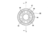
- the rollers 63 and 63 are, for example, metal roller bodies 64 and 64 and a collar 65 made of an elastic material such as a synthetic resin such as polyamide resin (nylon) or polytetrafluoroethylene resin (PTFE) or rubber. , 65.
- rollers 63, 63 can have other materials and / or other configurations.
- Each roller body 64, 64 has a substantially cylindrical shape as shown in FIGS.
- Through holes 66 and 66 through which the shaft portion 62 can be inserted are formed in the central portions of the roller main bodies 64 and 64.
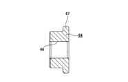
- Outward flange-shaped flange portions 67 and 67 are formed at the end portions in the width direction of the outer peripheral surfaces of the roller main bodies 64 and 64.
- the intermediate portions in the radial direction of the roller bodies 64, 64 there are thinned portions 68, 68 each having a substantially arc-shaped cross section that are recessed in the width direction at a plurality of circumferentially equidistant locations (four locations in the illustrated example). Is formed.
- the collars 65 and 65 have a cylindrical shape as shown in FIGS. The thickness dimension of the collars 65 and 65 is larger than the height dimension in the radial direction of the collar portions 67 and 67.
- the collars 65 and 65 are press-fitted (externally fitted) into portions of the outer peripheral surfaces of the roller main bodies 64 and 64 that are separated from the flange portions 67 and 67 in the width direction.
- a single roller that is long in the width direction such as a pair of rollers continuous in the width direction, can be used, or the entire roller can be made of synthetic resin or rubber.
- the anchor part 27a is provided in the width direction one end side of the adjustment rod 24a.
- An anchor portion 27a is engaged with a tilt adjusting long hole 23a formed in one support plate portion 22a so as not to be relatively rotatable.
- a cam device 69 including a drive side cam and a driven side cam and an adjustment lever are provided around a portion protruding in the width direction from the outer surface of the support plate portion 22a on the other side in the width direction. 26a is provided.
- a nut 70 is screwed onto the male screw portion.
- the driving cam of the cam device 69 is rotated relative to the driven cam on the basis of the swinging operation of the adjusting lever 26a, so that the width dimension of the cam device 69 (the axial direction of the adjusting rod 24a) is increased. (Dimensions in) are enlarged or reduced.
- the mounting plate 58 in the upper bracket 17a is provided with a tilt spring (tilt spring or balance spring) 72A that is a coil spring.
- a tilt spring 72A is bridged between a bent portion 71A provided at the front end portion of the mounting plate portion 58 and the cam device 69 (driven cam).
- the tilt spring 72A applies an upward biasing force to the adjustment rod 24a via the cam device 69.
- the urging force applied to the adjustment rod 24a is transmitted to the lower surface of each overhang plate portion 39, 39 constituting the upper side of each roller running concave groove 48, 48 via each roller 63, 63, and the outer column 11a. Is pushed upward.
- the steering device includes a steering lock device, which is a kind of vehicle antitheft device.
- a steering lock device which is a kind of vehicle antitheft device.
- a locking through hole 33a penetrating in the radial direction is formed in a portion near the front end of the cylindrical body 35.
- a lock unit 73 is supported and fixed around the lock through hole 33a, and a key lock collar 74 is externally fixed (press-fitted) to the steering shaft 2a.
- the key lock collar 74 is a part of the steering shaft 2a and is disposed at a portion where the phase in the axial direction coincides with the lock unit 73.
- the lock unit 73 when the ignition key is turned off, the tip of the lock pin 75 is displaced toward the inner diameter side of the outer column 11a, and the key lock recess 76 formed on the outer peripheral surface of the key lock collar 74 is engaged. Combined. Thereby, the rotation of the steering shaft 2a becomes substantially impossible. That is, the key lock recess 76 and the tip of the lock pin 75 are engaged in a state in which the steering shaft 2a is not substantially rotatable when the key is locked.
- the lock unit 73 is set with a predetermined value (for example, a value defined by key lock regulation, a limit value) for releasing the non-rotatable state.
- the steering shaft 2a is prevented from rotating with respect to a force that operates the steering wheel 1 (see FIG. 45) in a normal driving posture. When the steering wheel 1 (see FIG. 45) is rotated with a force equal to or greater than a predetermined value, the steering shaft 2a is allowed to rotate with respect to the key lock collar 74 and the steering column
- the tightening mechanism 80 is in the first state (first mode, first mode) in which the outer column 11a (steering column 4a) is tightened via the upper bracket (support bracket) 17a. And a second state in which the tightening is released (second mode, second mode).
- the adjustment lever 26a of the tightening mechanism 80 swings in a predetermined direction (generally upward) around the adjustment rod 24a. It is moved (turned). As a result, the width of the cam device 69 is increased, and the distance between the inner surfaces of the support plate portions 22a and 22a is reduced.
- the rollers 63, 63 are pressed toward the inner side in the width direction by the inner side surfaces of the support plate portions 22a, 22a.
- the working surfaces 40 and 40 (the bottom surfaces of the roller running grooves 48 and 48) formed at the lower end portions (tip portions) of the clamp portions 38 and 38 are pressed by the inner surfaces in the width direction of the rollers 63 and 63.
- the clamp portions 38 and 38 are bent inward in the width direction (toward the axial center) (elastic deformation), and the outer peripheral surface of the inner column 10a is elastically sandwiched (held) by the clamps 38 and 38 (tightening direction ( Tightened in the second direction). Thereby, the steering wheel 1 is held at the adjusted position. Further, when both the clamp portions 38, 38 are bent to some extent, the operation surfaces 49a, 49b (and the continuous flat surfaces 52a, 52b) are pressed inward in the width direction by the inner surfaces of the support plate portions 22a, 22a.
- the outer column 11a is clamped from both sides in the width direction by the inner surfaces of the support plate portions 22a and 22a via the operation surfaces 49a and 49b (tightened in the fastening direction (second direction)).
- the adjustment lever 26a is swung (turned) in the direction opposite to the predetermined direction (generally downward).
- the width dimension of the cam device 69 is reduced, and the distance between the inner surfaces of the support plate portions 22a and 22a is increased. Since the pressing force to the rollers 63, 63 by the support plate portions 22a, 22a is reduced, the width dimension between the clamp portions 38, 38 is elastically expanded, and the force for holding the outer peripheral surface of the inner column 10a is reduced. (Tightening is released).
- the front / rear position and the vertical position of the steering wheel 1 can be adjusted within a range in which the adjustment rod 24a can move within the telescopic adjustment long holes 21a, 21a and the tilt adjustment long holes 23a, 23a.
- the working surfaces 49a and 49a, the working surfaces 49b and 49b, and the working surfaces 40 of the clamp portions 38 and 38 are provided on both sides of the outer column 11a in the width direction (second direction, tightening direction). 40 is provided.
- the action surfaces 49a and 49a and the action surfaces 49b and 49b are directly pressed by the support plate portions 22a and 22a of the upper bracket 17a in the tightened state (first state).
- the working surfaces 40, 40 of the clamp portions 38, 38 are indirectly pressed by the support plate portions 22a, 22a via the rollers 63, 63 in the tightened state (first state).
- the working surface (first surface) 49a, the working surface (second surface) 49b, and the working surface (third surface) 40 are substantially independent of each other.
- the action surfaces 49a and 49a and the action surfaces 49b and 49b are provided on the frame body 34 of the outer column 11a, and the positions with respect to the inner column 10a are substantially changed in the transition from the open state (second state) to the tightened state (first state). Does not change or the amount of displacement is small.
- the working surface 40 of the clamp part 38 changes in position with respect to the inner column 10a by a relatively large displacement amount (displaced toward the inner column 10a). (Displacement surface).
- the outer column 11a and the support plate portions 22a and 22a are coupled to each other mainly at a position near the central axis of the outer column 11a by the force acting on the action surfaces 49a and 49a.
- the outer column 11a and the support plate portions 22a and 22b are coupled to each other mainly at a position away from the central axis of the outer column 11a by the force acting on the action surfaces 49b and 49b.
- the inner column 10 a is mainly held by the outer column 11 a via the clamp portion 38 due to the force acting on the action surfaces 40, 40. Therefore, in the steering device of this example, securing the strength of the outer column 11a and securing the holding force of the inner column 10a are realized simultaneously and independently, and a position adjusting mechanism having high stability is provided.
- FIG. 46 and 47 show a conventional steering device described in Patent Document 1.
- FIG. in the conventional steering device the outer column 11 is supported by the upper bracket 17 so as to be movable in the front-rear direction and the vertical direction so that the front-rear position and the vertical position of the steering wheel 1 can be adjusted.
- a slit 19 extending in the axial direction of the outer column 11 is formed on the lower surface of the front end portion of the outer column 11.
- a pair of clamp parts 20, 20 are formed integrally with the outer column 11 with the slit 19 being sandwiched from both sides in the width direction.
- Telescopic adjustment long holes 21 and 21 that are long in the front-rear direction are formed at positions where the clamp portions 20 and 20 are aligned with each other.
- the upper bracket 17 is provided with a pair of support plate portions 22 and 22 with the clamp portions 20 and 20 sandwiched from both sides in the width direction.
- Tilt adjusting long holes 23, 23 that are vertically aligned are formed in portions that are aligned with each other at a part of the support plate portions 22, 22 and are aligned with a part of the telescopic adjusting long holes 21, 21 in the front-rear direction.
- the adjustment rod 24 extends in the width direction (FIG. 47) in the telescopic adjustment long holes 21 and 21 and the tilt adjustment long holes 23 and 23. From right to left).
- An adjustment nut 25 is screwed to the other end of the adjustment rod 24.
- the adjustment nut 25 can be rotated by an adjustment lever 26.
- the adjusting nut 25 is rotated based on the operation of the adjusting lever 26.
- the outer column 11 is fixed to the upper bracket 17 or is not fixed.
- the outer column 11 is fixed with respect to the inner column 10 with the space
- the adjustment rod 24 can be displaced in the front-rear direction inside the telescopic adjustment long holes 21, 21.
- the front / rear position of the steering wheel 1 can be adjusted by moving the outer column 11 back and forth (relative displacement with respect to the inner column 10). Further, the adjustment rod 24 can be displaced in the substantially vertical direction inside the long holes 23 and 23 for tilt adjustment. The vertical position of the steering wheel 1 can be adjusted within this displaceable range (tilt adjustment range). At this time, the steering column 4 is oscillated and displaced in the vertical direction around the tilt shaft 16.
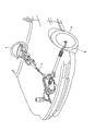
- the front end portion of the output shaft 13 of the steering force assisting device 5 is connected to the rear end portion of the intermediate shaft 29 via the universal joint 28.
- An input shaft 31 of the steering gear unit 7 is connected to the front end portion of the intermediate shaft 29 via another universal joint 30.
- the steering gear unit 7 includes a rack and a pinion (not shown), and an input shaft 31 is coupled to the pinion.
- the rack that meshes with the pinion is connected to tie rods 6 and 6 at both ends. By pushing and pulling these tie rods 6 and 6 based on the axial displacement of the rack, a desired steering angle is given to the steering wheel 3 (see FIG. 45).
- the steering force assisting device 5 can apply an assist torque with a predetermined magnitude in a predetermined direction to the output shaft 13 via the worm speed reducer by the electric motor 32.
- the frictional force between the inner surface of the support plate portions 22, 22 and the outer surface of the clamp portions 20, 20 is caused by an operation via the adjustment lever 26. If it falls, the rear-end part of the outer column 11 may incline below. This is because a downwardly directed force acts on the rear end portion of the outer column 11 via the outer shaft 9 based on the weight of the steering wheel 1.
- a certain amount of gap is provided between the inner peripheral surface of the outer column 11 and the outer peripheral surface of the inner column 10 due to the relative displacement in the axial direction between the inner column 10 and the outer column 11. It has been.
- the adjustment rod 24a is biased upward by the tilt spring 72A.
- This urging force F1 is transmitted to the front end portion (frame body 34) of the outer column 11a via the rollers 63, 63.
- the outer column 11a is pushed upward by the urging force F1 even when a force F2 is applied to the outer column 11a at the rear end, based on the weight of the steering wheel 1, in a direction to push the rear end of the outer column 11a downward. It is done.
- the inclination of the outer column 11a can be zero or reduced (the rear end can be prevented from being inclined downward).
- a gap is secured between the upper end portion of the inner peripheral surface of the outer column 11a and the upper end portion of the outer peripheral surface of the inner column 10a. Accordingly, the upper end portion of the rear end edge portion of the inner column 10a and the inner peripheral surface of the outer column 11a come into strong contact with each other by line contact. Therefore, it is possible to effectively prevent the occurrence of catching (twisting) when adjusting the front-rear position of the steering wheel 1.
- the urging force applied to the adjusting rod 24a is transmitted to the aura column 11a (the lower surfaces of the overhanging plate portions 39, 39) via the rollers 63, 63.
- the rollers 63, 63 travel along the lower surfaces of the projecting plate portions 39, 39 ( Roll).
- the sliding resistance can be reduced by interposing a resin sleeve or the like in the sliding contact portion between the adjustment rod and the outer column in order to ensure slidability.
- the surface pressure is increased and a problem of durability tends to occur.
- rolling contact is used, and such a problem is avoided.
- the collars 65, 65 made of synthetic resin are used on the outer peripheral surfaces of the rollers 63, 63, so that sliding based on contact between metals is avoided, and the rollers 63, 63 are effective. Can be rotated.
- the biasing force is applied to the adjustment rod 24a by the tilt spring 72A, so that the biasing force is applied throughout the entire front-rear adjustment range of the steering wheel 1.
- the rollers 63 and 63 are interposed, the front-rear position is smoothly adjusted in a state where the upward biasing force is applied.
- the sliding portion main body 55 is provided at the lower end portion of the front end edge portion of the outer column 11a (frame body 34), the upper surface of the sliding portion main body 55 is the inner column 11a. It is in contact with the outer peripheral surface. As a result, the contact state between the lower end portion of the front end edge portion of the outer column 11a and the outer peripheral surface of the inner column 10a is prevented from being a line contact. Therefore, it is possible to prevent the portion from being caught and to prevent the sliding resistance from being excessive when adjusting the front-rear position.
- the steering device of this example is preferably applied even when the total length of the steering column 4a is relatively short. That is, even when the configuration of the column EPS is adopted, the steering wheel 1 is prevented from being caught (twisted) at the time of adjusting the front / rear position, and a high operational feeling is obtained at the time of adjusting the front / rear position, and the operation load is kept low.
- a steering lock device for preventing theft as described in Patent Document 2 may be incorporated.
- the steering lock device is configured by mounting a lock unit (key lock cylinder) around a lock through-hole 33 formed in a part of the outer column 11 and a key lock collar on a part of the steering shaft 2. Is done. In a state where the ignition key is removed, the key lock pin provided in the lock unit and the key lock hole (concave portion) provided in the key lock collar are engaged, and the rotation of the steering shaft 2 with respect to the outer column 10 is prevented.
- the working surface 40 of the clamp part 38 and the working surfaces 49a and 49b are provided separately and independently on both sides in the width direction of the outer column 11a. It has been.
- the clamp portions 38 are used for elastically holding the outer peripheral surface of the inner column 10a.
- the torque acting on the outer column 11a is applied to the support plate portion of the upper bracket 17a via the action surfaces 49a and 49b. It is transmitted to the inner surface of 22a, 22a.
- the clamp parts 38 and 38 are sufficient if only the function of clamping the inner column 10a can be exhibited.
- a desired deflection characteristic can be set for the clamp portions 38, 38, such as greatly bending the clamp portions 38, 38 in the width direction.
- the action surfaces 49a and 49b need only exhibit the function of transmitting torque. Therefore, it is not necessary to greatly bend the portion of the outer column 11a where the operation surfaces 49a and 49b are provided in the width direction. Therefore, according to the steering apparatus of this example, ensuring the strength of the outer column 11a and ensuring the holding force of the inner column 10a can be achieved independently.
- the inner surfaces of the support plate portions 22a and 22a are brought into contact (pressed) with the operation surfaces 49a and 49b.
- the clamp portions 38 and 38 are bent through the inner side surfaces of the support plate portions 22a and 22a.
- the operation surfaces 49a and 49b are substantially independent from the operation surface 40 of the clamp portion 38, and the portion provided with the operation surfaces 49a and 49b has a sufficiently high rigidity compared to the clamp portion 38. (Flexural rigidity, deflection characteristics).
- the working surface 49a and the working surface 49b are spaced apart from each other in a first direction that intersects the second direction (tightening direction).
- the position of the working surface 49b is outside the range of the outer shape of the inner column 10a in the first direction, and further outside the range of the outer shape of the cylindrical body 35 of the outer column 11a. Therefore, the torque acting on the outer column 11a is absorbed through the acting surfaces 49a and 49b, and the torque is prevented from being transmitted to the clamp portion 38.
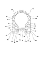
- each clamp portion 38a projected on a virtual plane that is orthogonal to the central axis O 11 of the outer column 11b, the cross-sectional shape of the 38a, the clamping portion 38a, between 38a between the center axis O 11 of the outer column 11b together through, with respect to the imaginary line V that is perpendicular to the central axis O 21 of the elongated hole (slit) 21b, 21b, having a symmetrical shape.
- the cross-sectional shape of each clamp part 38a, 38a is constant over the axial direction full length (shape symmetrical with respect to the front-back direction).
- the clamp part 38a has a substantially symmetrical shape and symmetrical structure with respect to a symmetrical axis along the first direction intersecting the axial direction.
- the action surface 40 of the clamp portion 38a has a shape that is substantially symmetrical with respect to the symmetry axis. That is, the center of the action surface 40 in the axial direction is located on the axis of symmetry.
- the centers of the working surface 49c and the working surface 49d of the outer column 11a in the axial direction coincide with the center of the clamp portion 38a.
- the centers of the action surface 49c and the action surface 49d in the axial direction coincide with the center of the action surface 40 of the clamp portion 38a.
- the center of the telescopic adjustment long hole 21a coincides with the centers of the action surface 49c, the action surface 49d, and the action surface 40.
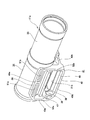
- circumferential slits 37c and 37d extending linearly in the circumferential direction are formed in the frame 34a of the outer column 11b.
- the circumferential slits 37c and 37d are provided so as to intersect in the circumferential direction portions near the front and rear ends of the axial slit 36 formed on the lower surface of the frame 34a.
- Clamp portions 38a surrounded by three sides by an axial slit 36, a circumferential slit 37c, and a circumferential slit 37d are formed on both sides in the width direction of the frame 34a.
- a gap 47a (slit) is formed between the clamp portion 38a and the reinforcing bridge portion 41.
- the gap 47a has a substantially U-shape (substantially U-shape) in which the front and rear end portions are bent at a right angle when viewed from the width direction.
- Torque acting on the outer column 11b is transmitted to the inner side surfaces of the support plate portions 22a and 22a of the upper bracket 17a (see FIG. 2 and the like) via the action surfaces 49c and 49d.
- Each of the working surfaces 49c and 49d has a symmetrical shape with respect to the front-rear direction.
- the action surfaces 49c and 49d and the continuous flat surfaces 52a and 52b are continuous in a rectangular (square) frame shape.
- the clamp portions 38a and 38a are bent by the inner surfaces of the support plate portions 22a and 22a in order to hold the steering wheel 1 (see FIG. 46) in a desired position.
- stress is prevented from concentrating on a part of the clamp portions 38a, 38a regardless of the front and rear positions of the adjustment rod 24a (see FIG. 2) in the telescopic adjustment long holes 21b, 21b. Therefore, various directions acting on the clamp portions 38a and 38a (the lower surface and the pressing surface 40 of the protruding plate portion 39) from the rollers 63 and 63 disposed in the telescopic adjustment long holes 21b and 21b ⁇ vertical direction (horizontal direction in FIG.
- the bending amounts of the clamp portions 38a and 38a to be the same, the holding force of the inner column 10a is stabilized.
- the longitudinal dimensions of the telescopic adjustment long holes 21b and 21b can be designed larger than in the case of the first example. In this case, the adjustment length in the front-rear direction of the steering wheel 1 is increased. About another structure and an effect, it is the same as that of the case of a 1st example.
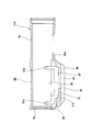
- the structures of the clamp portions 38 and 38 are particularly different from the structure of the first example of the embodiment described above.
- projecting plate portions (projecting portions) 39 and 39 are provided at the lower end portions of the outer surfaces in the width direction of the clamp portions 38 and 38 so as to protrude outward in the width direction (second direction).
- Action surfaces (third surface, third action surface, pressing surface) 40, 40 are formed on the outer side in the width direction (second direction) of each of the projecting plate portions 39, 39.
- the working surface 40 has a flat surface shape. Additionally and / or alternatively, the working surface 40 can have a shape other than flat.
- Reinforcing ribs 51, 51 are provided between the upper surfaces (side surfaces of the walls) of the overhanging plate portions 39, 39 and the cylindrical surface-like upper end portion or intermediate portion of the outer side surfaces in the width direction of the clamp portions 38, 38. Is provided. On each side, the plurality of reinforcing ribs 51 (five examples in the figure) are provided to extend in the width direction and are spaced apart from each other in the front-rear direction (axial direction).
- the outer column 11a has a reinforcing bridge portion (reinforcing portion, reinforcing structure, reinforcing member) 41 bridged between both sides of the outer column 11a in the width direction (second direction).
- the reinforcing bridge portion 41 extends substantially continuously between both sides of the outer column 11a in the width direction (second direction), and physically between both sides of the outer column 11a in the width direction (second direction). It is provided to connect.
- a reinforcing bridge portion 41 is provided in a lower portion of the frame body 34 so as to cover both the clamp portions 38 and 38 from below.
- the reinforcing bridge portion 41 is provided integrally with the outer column 11a.
- the reinforcing bridge portion 41 includes a reinforcing plate portion 42 and a pair of connecting portions 43a and 43b.
- the shape of the reinforcing bridge portion 41 as viewed from the width direction has a substantially U shape (U shape).
- the reinforcing plate portion 42 is disposed below the clamp portions 38 and 38 and is provided in a state of extending in the width direction and the front-rear direction.
- the reinforcing plate portion 42 includes a flat plate portion 44 disposed in parallel to the central axis of the outer column 11a, and a pair of downward extending portions provided to extend downward from the lower surfaces of both ends of the flat plate portion 44 in the width direction. It has the output parts 45 and 45.
- the reinforcing plate portion 42 has a substantially U-shaped cross section. Further, a notch 46 penetrating in the vertical direction is formed in the intermediate portion in the width direction of the front end portion of the reinforcing plate portion 42 (flat plate portion 44). Also, flat reinforcing connecting plates 52, 52 extending in the width direction are spaced apart in the front-rear direction between the lower surface of the width direction intermediate portion of the flat plate portion 44 and the inner surface of the lower extension portions 45, 45 in the width direction. In this state, a plurality (three in the illustrated example) are provided.
- the connecting portion 43a disposed relatively forward is provided so as to extend upward from both side portions in the width direction of the front end portion of the reinforcing plate portion 42 (both side portions of the notch 46).
- the connecting portion 43 a is a portion adjacent to the front side of the circumferential slit 37 a on the lower surface of the front end portion of the frame body 34, and is connected to both sides in the circumferential direction across the axial slit (first slit portion) 36.
- the connecting portion 43 b disposed relatively rearward is provided so as to extend upward from the rear end portion of the reinforcing plate portion 42.
- the connecting portion 43 b is connected to a portion adjacent to the rear side of the rear end portion of the axial slit 36 on the lower surface of the rear end portion of the frame body 34.
- the reinforcing bridge portion 41 can have a different configuration from that described above.
- the outer column 11a has a high torsional rigidity by including the reinforcing bridge portion 41 as described above.
- interval (slit) 47 and 47 whose shape seen from the width direction (2nd direction) is substantially U shape (U shape) is formed.
- the gaps 47, 47 are telescopic adjustment long holes (axial slit, first slit portion, first through hole) 21a, 21a extending at least in the axial direction (axial direction of the outer column 11a, axial direction of the steering shaft 2a).
- second slit portions 37a and 37b that are provided continuously to the long holes 21a and 21a and extend in a direction intersecting the long holes 21a and 21a.
- the clamp parts 38 and 38 are provided adjacent to the long holes 21a and 21a.
- the long holes 21a and 21a form a space that exists between the tip end portions (lower end portions) of the clamp portions 38 and 38 and the upper surface of the reinforcing plate portion 42 (flat plate portion 44).
- the adjustment rod 24a is inserted through the long holes 21a and 21a in the width direction (second direction).
- the outer column 11a includes a working surface (first surface, first working surface, first contact surface, torque transmission surface) 49a and working surface (second surface, provided on each of two side surfaces in the width direction. Second working surface, second contact surface, torque transmission surface) 49b.
- the working surface 49a and the working surface 49b are arranged to be separated from each other in a first direction (first crossing direction) that intersects the axial direction (the axial direction of the outer column 11a, the axial direction of the steering shaft 2a). .
- first crossing direction that intersects the axial direction (the axial direction of the outer column 11a, the axial direction of the steering shaft 2a).
- the clamp portion 38 and the action surface 40
- the action surface 49b is disposed between the action surface 49a and the action surface 49b.
- the adjustment rod 24a is disposed between the action surface 49a and the action surface 49b in the first direction
- the action surface 40 of the clamp portion 38 is between the action surface 49a and the adjustment rod 24a in the first direction.
- the axial slit 36 (the long hole 21a) is disposed between the working surface 49a and the working surface 49b in the first direction.
- torque force in the torsional direction acting on the outer column 11a can be transmitted to the inner side surfaces of the support plate portions 22a and 22a in the upper bracket 17a via the action surface 49a and the action surface 49b.
- the working surface 49a is disposed within the range of the outer shape of the inner column 10a in the first direction.
- the action surface 49b is disposed outside the range of the outer shape of the inner column 10a in the first direction. Furthermore, the action surface 49b is disposed outside the range of the outer shape of the cylindrical body 35 of the outer column 11a. Further, in the first direction, the working surface 49a is disposed relatively near the central axis of the inner column 10a, and the working surface 49b is disposed relatively far from the central axis of the inner column 10a.
- the outer column 11a protrudes outward in the width direction (second direction) in a portion overlapping the central axis of the outer column 11a in the first direction (or up and down direction).
- Strips 50a and 50a are provided.
- the protrusion 50a is provided to extend to the outer column 11a.
- Action surfaces 49a and 49a are provided at the tip (width direction outer surface) of the protrusion 50a.
- Projection portions 50b and 50b are provided at the lower end portion of the outer surfaces in the width direction of the downward extending portions 45 and 45 so as to protrude outward in the width direction (second direction).
- the protrusion 50b is provided extending in the axial direction of the outer column 11a.
- Action surfaces 49b and 49b are provided at the tip (width direction outer surface) of the protrusion 50b. That is, both of the working surfaces 49a and 49b have a shape extending in the axial direction of the outer column 11a and have a length that is larger in the axial direction than the clamp portion 38. For example, each of the working surface 49a and the working surface 49b has a flat surface shape. Additionally and / or alternatively, the working surface 49a and the working surface 49b may have a shape other than a flat shape.
- the action surfaces 49a and 49b have higher rigidity in the width direction (second direction) than the clamp portions 38 and 38.
- the working surfaces 40, 40 are arranged between the working surfaces 49a, 49a and the working surfaces 49b, 49b in the first direction.
- the working surfaces 49a and 49a, the working surfaces 49b and 49b, and the working surfaces 40 and 40 may have a positional relationship other than the above.
- the front-rear direction dimensions (X, Z) of the operation surfaces 49a, 49b arranged above and below are larger than the front-rear direction dimension (Y) of the operation surface 40 ( X> Y, Z> Y).
- the front-rear direction dimension (X) of the action surface 49a is substantially the same as the front-rear direction dimension (Z) of the action surface 49b (X ⁇ Z).
- the distance from the center in the front-rear direction of the telescopic adjustment long hole 21a to the front edge of the working surface 49a is approximately the distance from the center in the front-rear direction of the long hole 21a to the rear edge of the working surface 49a. It is set to be the same. The same applies to the front edge and the rear edge of each of the working surface 49b and the working surface 40.
- the working surface 40 of the clamp portion 38 may have a shape that is substantially symmetric with respect to a predetermined symmetry axis, or may be asymmetric with respect to the symmetry axis. Further, in the axial direction, the center of the clamp portion 38 (and / or the center of the working surface 40) may coincide with the centers of the working surface 49a and the working surface 49b, or may be offset. Moreover, the shape and / or structure of the clamp part 38 may be provided offset in the axial direction with respect to the working surface 49a and the working surface 49b.
- the center of the clamp portion 38 (and / or the center of the working surface 40) can be positioned forward (or rearward) with respect to the respective centers of the working surface 49a and the working surface 49b of the outer column 11a.
- the center of the telescopic adjustment long hole 21a may coincide with at least one of the working surface 49a, the working surface 49b, and the working surface 40, or may be offset.
- the center of the action surface 40 of the clamp part 38 can be positioned forward with respect to the center of the long hole 21a.
- the operating surface 40 is offset in the axial direction, so that the operating force of the adjusting lever 26a can be made difficult to change even when the front-rear position of the steering wheel 1 (see FIGS. 45 and 46) changes. it can.
- the fitting margin between the rear end portion of the inner column 10a and the front end portion of the outer column 11a is relatively short, and the working surface 40 is formed of the inner column. Tighten the rear end portion of 10a.
- the rear end portion of the inner column 10a has a lower rigidity than the intermediate portion, so that the tightening reaction force is relatively low and the operating force of the adjustment lever 26a is relatively low.
- the upper ends of the connecting portions 43a and 43b in the reinforcing bridge portion 41 are continuous with the front and rear ends of the ridge portions 50a and 50b.
- the width direction outer side surfaces of the connecting portions 43a and 43b are positioned (offset) inward in the width direction with respect to the action surface 49a, the action surface 49b, and the action surface 40.
- the inner side surfaces of the support plate portions 22a and 22a in the upper bracket 17a can be prevented from substantially contacting the outer side surfaces in the width direction of the connecting portions 43a and 43b.
- the outer column 11a of this example a pair of sandwiched plate portions are provided integrally with the outer column 11a in a state where the axial slit 36 is sandwiched from both sides in the width direction, and the distal end portions of the both sandwiched plate portions are provided.
- the (lower end portions) are connected in the width direction (by the portion corresponding to the reinforcing plate portion 42).
- the outer side surfaces in the width direction of the both sandwiched plate portions are respectively substantially flat clamping surfaces.
- the upper bracket (support bracket) 17a is made of a metal plate having sufficient rigidity, such as steel or an aluminum-based alloy.
- the upper bracket 17a has a mounting plate portion 58 and a pair of support plate portions 22a and 22a.
- the attachment plate portion 58 is normally supported with respect to the vehicle body 15a.
- the mounting plate portion 58 is configured so that the mounting plate portion 58 is detached forward based on an impact such as a secondary collision, and the outer column 11a is allowed to move forward.
- a pair of locking notches 59 and 59 are formed in the rear end edge of the mounting plate portion 58 in an open state.
- a locking capsule 18a fixed to the vehicle body 15a by a fixing member such as a bolt or a stud is locked to the locking notches 59, 59.
- the support plate portions 22 a and 22 a are provided so as to hang down from the mounting plate portion 58.
- the support plate portions 22a and 22a are provided so as to be parallel to each other with the front end portion (the frame body 34 and the reinforcing bridge portion 41) of the outer column 11a sandwiched from both sides in the width direction.
- the pair of support plate portions 22a and 22a are arranged on both sides of the outer column 11a in the width direction (second direction).
- Tilt adjusting long holes (second through holes) 23a and 23a extending at least in the vertical direction (first direction) are formed in the support plate portions 22a and 22a.
- the long holes 23a and 23a are provided at positions facing each other in the width direction (positions aligned with each other).
- the long holes 23a and 23a are provided so as to be aligned with a part of the telescopic adjustment long holes 21a and 21a in the front-rear direction.
- the long holes 23a, 23a have a long axis along the vertical direction (first direction).
- the support plate portions 22a and 22a are arranged so that the outer column 11a (the steering column 4a) can be tightened by using the tightening mechanism 80.
- the tightening mechanism 80 includes an adjustment rod 24a, an adjustment nut 25, an adjustment lever 26a, and the like (see FIG. 28).
- An adjusting rod 24a is inserted through the telescopic adjusting long holes 21a and 21a and the tilt adjusting long holes 23a and 23a in the width direction.
- the adjustment rod 24a In the width direction (the axial direction of the adjustment rod 24a, the second direction), the adjustment rod 24a has an anchor portion disposed at one end, a male screw portion formed at the other end, and a shaft portion formed at the intermediate portion. And.
- the adjustment rod 24a is disposed through the telescopic adjustment long holes 21a and 21a and the tilt adjustment long holes 23a and 23a.
- An anchor portion is provided on one end side in the width direction of the adjusting rod 24a.
- An angling portion is engaged with a tilt adjusting long hole 23a formed in one support plate portion 22a so as not to be relatively rotatable.
- a cam device 69 including a driving cam and a driven cam and an adjusting lever 26a are provided around a portion protruding in the width direction from the outer surface of the support plate portion 22a on the other side in the width direction. Is provided.
- a nut 70 is screwed onto the male screw portion.
- the cam device 69 driven cam is rotated relative to the driven cam based on the swinging operation of the adjustment lever 26a, whereby the width dimension of the cam device 69 (the axial direction of the adjustment rod 24a). (Dimensions in) are enlarged or reduced.
- the steering device includes a steering lock device, which is a kind of vehicle antitheft device.
- a steering lock device which is a kind of vehicle antitheft device.
- a locking through-hole 33a penetrating in the radial direction is formed in the cylindrical body 35.
- a fixing portion 71 for supporting and fixing a lock unit (not shown) is provided on a portion of the outer peripheral surface of the cylindrical body 35 that is removed from the locking through hole 33a in the circumferential direction.
- the fixed portion 71 is provided with a pair of mounting flanges 72, 72.
- a lock unit is supported and fixed using mounting flanges 72, 72, and a key lock collar (not shown) is externally fitted (press-fitted) to the steering shaft 2a.
- the key lock collar is a part of the steering shaft 2a and is disposed at a portion where the phase in the axial direction coincides with the lock unit.
- the tip of the lock pin in the lock unit is displaced toward the inner diameter side of the outer column 11a and engages with the key lock recess formed on the outer peripheral surface of the key lock collar. Is done.
- the rotation of the steering shaft 2a becomes substantially impossible. That is, the key lock recess and the tip of the lock pin are engaged when the steering shaft 2a is substantially unable to rotate when the key is locked.
- a predetermined value for example, a value defined by key lock regulation, a limit value for releasing the non-rotatable state is set in the lock unit.
- the steering shaft 2a is prevented from rotating with respect to a force that operates the steering wheel 1 (see FIG. 45) in a normal driving posture.
- the steering wheel 1 see FIGS. 45 and 46
- the steering shaft 2a is allowed to rotate with respect to the key lock collar and the steering column 4a.
- the tightening mechanism 80 is in the first state (first mode, first mode) in which the outer column 11a (steering column 4a) is tightened via the upper bracket (support bracket) 17a. And a second state in which the tightening is released (second mode, second mode).
- the adjustment lever 26a of the tightening mechanism 80 swings in a predetermined direction (generally upward) around the adjustment rod 24a. It is moved (turned). As a result, the width of the cam device 69 is increased, and the distance between the inner surfaces of the support plate portions 22a and 22a is reduced.
- the action surfaces 49a and 49a, the action surfaces 49b and 49b, and the action surfaces 40 and 40 of the clamp portions 38 and 38 are pressed by the inner side surfaces of the support plate portions 22a and 22a.
- the intermediate portions in the vertical direction of the support plate portions 22a and 22b and the clamp portions 38 and 38 bend inward in the width direction (toward the axial center) (elastic deformation), and the outer peripheral surface of the inner column 10a is elastically sandwiched between them. (Held) (tightened in the fastening direction (second direction)). Thereby, the steering wheel 1 is held at the adjusted position.
- the adjustment lever 26a is swung (turned) in the direction opposite to the predetermined direction (generally downward).
- the width dimension of the cam device 69 is reduced, and the distance between the inner surfaces of the support plate portions 22a and 22a is increased. Since the pressing force (clamping force) by the support plate portions 22a and 22a is reduced, the width dimension between the clamp portions 38 and 38 is elastically expanded, and the force for holding the outer peripheral surface of the inner column 10a is reduced (clamping is not performed). Released).
- the front / rear position and the vertical position of the steering wheel 1 can be adjusted within a range in which the adjustment rod 24a can move within the telescopic adjustment long holes 21a, 21a and the tilt adjustment long holes 23a, 23a.
- the working surfaces 49a and 49a, the working surfaces 49b and 49b, and the working surfaces 40 of the clamp portions 38 and 38 are provided on both sides of the outer column 11a in the width direction (second direction, tightening direction). 40 is provided.
- the action surfaces 49a and 49a and the action surfaces 49b and 49b are directly pressed by the support plate portions 22a and 22a of the upper bracket 17a in the tightened state (first state).
- the working surfaces 40, 40 of the clamp portions 38, 38 are directly pressed by the support plate portions 22a, 22a in the tightened state (first state).
- the working surface (first surface) 49a, the working surface (second surface) 49b, and the working surface (third surface) 40 are substantially independent of each other.
- the action surfaces 49a and 49a and the action surfaces 49b and 49b are provided on the frame body 34 of the outer column 11a, and the positions with respect to the inner column 10a are substantially changed in the transition from the open state (second state) to the tightened state (first state). Does not change or the amount of displacement is small.
- the working surface 40 of the clamp part 38 changes in position with respect to the inner column 10a by a relatively large displacement amount (displaced toward the inner column 10a). (Displacement surface).
- the outer column 11a and the support plate portions 22a and 22a are coupled to each other mainly at a position near the central axis of the outer column 11a by the force acting on the action surfaces 49a and 49a.
- the outer column 11a and the support plate portions 22a and 22b are coupled to each other mainly at a position away from the central axis of the outer column 11a by the force acting on the action surfaces 49b and 49b.
- the inner column 10 a is mainly held by the outer column 11 a via the clamp portion 38 due to the force acting on the action surfaces 40, 40. Therefore, in the steering device of this example, securing the strength of the outer column 11a and securing the holding force of the inner column 10a are realized simultaneously and independently, and a position adjusting mechanism having high stability is provided.
- the working surface 40 of the clamp portion 38 and the working surfaces 49a and 49b are provided separately and independently on both sides in the width direction of the outer column 11a. It has been.
- the clamp portions 38 are used for elastically holding the outer peripheral surface of the inner column 10a.
- the torque acting on the outer column 11a is applied to the support plate portion of the upper bracket 17a via the action surfaces 49a and 49b. It is transmitted to the inner surface of 22a, 22a.
- the clamp parts 38 and 38 are sufficient if only the function of clamping the inner column 10a can be exhibited.
- a desired deflection characteristic can be set for the clamp portions 38, 38, such as greatly bending the clamp portions 38, 38 in the width direction.
- the action surfaces 49a and 49b need only exhibit the function of transmitting torque. Therefore, it is not necessary to greatly bend the portion of the outer column 11a where the operation surfaces 49a and 49b are provided in the width direction. Therefore, according to the steering apparatus of this example, ensuring the strength of the outer column 11a and ensuring the holding force of the inner column 10a can be achieved independently.
- the inner surfaces of the support plate portions 22a and 22a are brought into contact (pressed) with the operation surfaces 49a and 49b.
- the clamp portions 38 and 38 are bent through the inner side surfaces of the support plate portions 22a and 22a.
- the operation surfaces 49a and 49b are substantially independent from the operation surface 40 of the clamp portion 38, and the portion provided with the operation surfaces 49a and 49b has a sufficiently high rigidity compared to the clamp portion 38. (Flexural rigidity, deflection characteristics).
- the working surface 49a and the working surface 49b are spaced apart from each other in a first direction that intersects the second direction (tightening direction).
- the position of the working surface 49b is outside the range of the outer shape of the inner column 10a in the first direction, and further outside the range of the outer shape of the cylindrical body 35 of the outer column 11a. Therefore, the torque acting on the outer column 11a is absorbed through the acting surfaces 49a and 49b, and the torque is prevented from being transmitted to the clamp portion 38.
- the outer side surfaces in the width direction of the connecting portions 43a and 43b are positioned (offset) inward in the width direction with respect to the action surfaces 49a and 49b and the action surfaces 40 and 40. Therefore, when shifting from the state in which the position of the steering wheel 1 can be adjusted (second state) to the state in which the position of the steering wheel 1 can be held (first state), the inner surface of the support plate portion 22a is connected to the connecting portion 43a. , 43b does not contact the outer side surface in the width direction.
- the inner surfaces of the support plate portions 22a and 22a are mainly the action surfaces 49a and 49a, the action surfaces 49b and 49b, and the action surface 40, 40 is pressed. Therefore, regardless of the position of the steering wheel 1 in the front-rear direction, the area of the portion pressed by the inner side surface of the support plate portion 22a (the contact surface 49a, the operation surface 49b, and the operation surface 40 with the support plate portion 22a) Area) is constant (or falls within a predetermined range). As a result, when the position of the steering wheel 1 in the front-rear direction is adjusted, a change in the tightening torque of the adjustment lever 26a is suppressed to a small level. Therefore, stable operability can be obtained in the operation of the adjusting lever 26a.
- the structure of the clamp portions 38 and 38 is particularly different from the third example of the embodiment described above.
- axial slits 36 long holes 21a, 21a
- slits 37a, 37b in a direction intersecting the axial direction, and the like continue on both sides in the width direction of the outer column 11a.
- the clamp portions 38 and 38 are provided.
- Each clamp part 38 has a cantilever structure having a fixed end extending in the axial direction.
- each of the clamp portions 38, 38 has a substantially different cross-sectional structure between the central portion and the end portion in the axial direction.
- the region near the center in the axial direction has a smaller thickness than the region near the end in the axial direction.
- the two regions (front part 81a and rear part 81b) close to the end of the clamp part 38 in the axial direction have the first wall thickness uniformly.
- the region near the center of the clamp portion 38 in the axial direction (intermediate portion 81c) has a second thickness that is uniformly smaller than the first thickness.
- reinforcing ribs 51 are provided in the vicinity of both ends in the axial direction (front portion 81a and rear portion 81b), and such reinforcing ribs are provided in the vicinity of the center in the axial direction (intermediate portion 81c). Is not provided.
- the clamp portion 38 may have another cross-sectional structure.
- the clamp part 38 has a cross-sectional structure that contributes to low rigidity partially in the vicinity of the center (intermediate part 81c).
- the clamp portion 38 has a cross-sectional structure that contributes to high rigidity partially in the vicinity of both ends in the axial direction (the front portion 81a and the rear portion 81b).
- the clamp portion 38 of this example has the same rigidity (bending rigidity, deflection characteristics) in the region (front portion 81a, rear portion 81b) in the vicinity of the opened end as that in the vicinity of the center (intermediate portion 81c). It is controlled to become. That is, the clamp part 38 has a substantially uniform rigidity distribution as a whole along the axial direction.
- the axial position of the adjusting rod 24a (see FIG. 28) with respect to the outer column 11a changes. That is, at the reference position, the adjustment rod 24a is positioned at the center of the long hole 21a in the axial direction.
- the tightening force of the tightening mechanism 80 acts mainly on the center of the clamp portion 38.
- the adjustment rod 24a inserted through the long hole 21a of the outer column 11a is positioned forward of the center of the long hole 21a.
- a clamping force acts mainly at a relatively forward position of the clamp portion 38.
- the adjustment rod 24a is located behind the center of the long hole 21a. In this case, a clamping force acts mainly at a relatively rear position of the clamp portion 38.
- the steering device of this example has a stable operation feeling with respect to the operation of the adjustment lever 26a.
- the clamp part 38 has a substantially symmetrical shape and symmetrical structure with respect to the symmetrical axis W along the first direction intersecting the axial direction.
- the two end regions having the first thickness (the front portion 81 a and the rear portion 81 b) have a substantially symmetrical structure with respect to the symmetry axis W.
- the central region (intermediate portion 81c) having the second thickness also has a substantially symmetrical structure with respect to the symmetry axis W.
- the distance from the symmetry axis W of the reinforcing rib 51 arranged near one end is substantially the same as that of the reinforcing rib 51 arranged near the other end (rear part).
- the working surface 40 of the clamp portion 38 has a shape that is substantially symmetric with respect to the symmetry axis W. That is, the center of the working surface 40 in the axial direction is located on the symmetry axis W. Furthermore, in this example, the centers of the working surface 49a and the working surface 49b of the outer column 11a in the axial direction coincide with the center of the clamp portion 38. For example, the centers of the action surface 49 a and the action surface 49 b in the axial direction coincide with the center of the action surface 40 of the clamp portion 38.
- the shape and / or structure of the clamp portion 38 may be asymmetric with respect to the symmetry axis W.
- the shape and / or structure of the clamp portion 38 may be provided offset in the axial direction with respect to the working surface 49a and the working surface 49b, as in the third example.
- the center of the clamp portion 38 (and / or the center of the working surface 40) can be positioned forward (or rearward) with respect to the respective centers of the working surface 49a and the working surface 49b of the outer column 11a.
- the center of the telescopic adjustment long hole 21a may coincide with at least one of the center of the working surface 49a, the working surface 49b, and the working surface 40, or may be offset.
- FIG. 41 to 44 A fifth example of the embodiment of the present invention will be described with reference to FIGS. 41 to 44.
- FIG. In the following description, the same or equivalent components as those in the above-described embodiment are denoted by the same reference numerals, and the description thereof is simplified or omitted.
- the outer column 11a includes an action surface 49a and an action surface 49b provided on each of two sides in the width direction.
- the outer column 11a further includes a clamp portion 38 for sandwiching the inner column 10a.
- the working surface 49a and the working surface 49b are spaced apart from each other in a first direction that intersects the axial direction.
- the working surface 40 of the clamp portion 38 is disposed between the working surface 49a and the working surface 49b in the first direction.
- the action surface 40 of the clamp part 38 is provided independently of the action surface 49a and the action surface 49b.
- the working surface 49a and the working surface 49b are also independent of each other.
- the action surface 49a and the action surface 49b are provided on the frame body 34 of the outer column 11a, and the position with respect to the inner column 10a does not substantially change in the transition from the open state (second state) to the tightened state (first state). Or the displacement amount is slight.
- the action surface 40 of the clamp part 38 is a displacement surface whose position with respect to the inner column 10a changes (displaces toward the inner column 10a) in the transition from the open state (second state) to the tightened state (first state). .
- the outer column 11a further has restriction surfaces (sitting surface, fourth surface) 84 for restricting the tightening amount provided on each of two sides in the width direction.
- the limiting surface 84 is provided on the frame body 34 of the outer column 11a.
- the portion where the restriction surface 84 is provided has higher rigidity (bending rigidity, deflection characteristics) than the clamp part 38.
- the position of the restriction surface 84 with respect to the inner column 10a does not substantially change in the transition from the open state (second state) to the tightened state (first state). Even when the limiting surface 84 is slightly displaced, the amount of displacement is set sufficiently lower than the amount of displacement of the working surface 40 of the clamp portion 38.
- the limiting surface 84 is provided so as to extend in the axial direction, and can have the same length as the working surface 40 in the axial direction.
- the limiting surface 84 has a flat surface shape.
- the limiting surface 84 can have a shape other than flat.
- the limiting surface 84 is disposed between the working surface 40 and the working surface 49b in the first direction.
- the limiting surface 84 can be arranged between the working surface 49a and the working surface 40 in the first direction.
- the limiting surface 84 is disposed adjacent to the axial slit 36 and / or the long hole 21a for the adjusting rod 24a (see FIG. 28) in the first direction.
- the limiting surface 84 can be disposed adjacent to the circumferential slit 37a and / or the circumferential slit 37b.
- the limiting surface 84 is provided independently from the working surface 49a, the working surface 49b, and the working surface 40. Further, the limiting surface 84 has a substantially lower surface height in the width direction (tightening direction, second direction) than the operation surface 49 a, the operation surface 49 b, and the operation surface 40. That is, as shown in FIG. 42, in the state where the tightening is released (second state), the width dimension Hd between the restricting surfaces 84 and 84 is larger than the width dimension Hc between the working surfaces 40 and 40 of the clamp part 38. Is small (Hc> Hd). In other words, in the second direction, a gap Gp corresponding to the tightening amount is provided between the working surface 40 and the limiting surface 84.
- Other configurations can be made similar to the fourth example of the above-described embodiment.
- the limiting surface 84 is disposed between the working surface 49a and the working surface 49b in the first direction. That is, the action surface 40 of the clamp part 38 and the restriction surface 84 are arranged between the action surface 49a and the action surface 49b.
- the distance from the center of the long hole 21a of the restriction surface 84 (the axis of the adjustment rod 24a) can be set to be approximately the same as that of the working surface 40.
- the upper bracket 17a in the transition from the open state (second state) to the tightened state (first state), the upper bracket 17a is bent by the operation of the adjustment lever 26a, and the interval between the support plate portions 22a and 22a is reduced. As a result, the inner side surface of the support plate portion 22a comes into contact with the working surface (first surface) 49a, the working surface (second surface) 49b, and the working surface (third surface) 40. Thereafter, the spacing between the support plate portions 22a and 22a of the upper bracket 17a can be further reduced by further operation of the adjustment lever 26a.
- the inward displacement amount (deflection amount) of the upper brackets 17a, 17a is limited by the limiting surfaces (fourth surfaces) 84, 84 provided on the frame body 34 of the outer column 11a. .
- the action surface 40 pushed by the support plate portion 22a is displaced inward in the width direction (toward the axis of the outer column 11a).
- the inner surface of the support plate portion 22 contacts the restriction surface 84. Even if pushed by the support plate portion 22a, the limiting surface 84 is not substantially displaced.
- the displacement (deflection) of the support plate portion 22a toward the axial center of the outer column 11a is forcibly stopped after contacting the limiting surface 84.
- the displacement (deflection) of the clamp portion 38 toward the axis of the outer column 11a also stops. That is, even if the adjusting lever 26a is further operated after the support plate portion 22a abuts on the limiting surface 84, an increase in holding force with respect to the inner column 10a by the clamp portion 38 is prevented.
- the telescopic holding force with respect to a predetermined lever operating force changes according to the rigidity of the upper bracket 17a. That is, when the rigidity of the upper bracket 17a is relatively high, the telescopic holding force with respect to a predetermined lever operating force is relatively low. If the outer column 11a is not provided with the restricting surface 84, as shown in the part (B) of FIG. 44, the design requirement range of the lever operating force with respect to the standard in which the upper limit of the telescopic holding force is restricted. Tends to be narrower than the line management range.
- the outer column is not limited to a structure in which a light alloy frame and an iron alloy cylinder are connected, and the outer column may be made of a light alloy such as an aluminum alloy or a magnesium alloy as a whole.
- the steering device may have a structure including both a tilt adjustment mechanism and a telescopic adjustment mechanism, or may have a structure including only a telescopic adjustment mechanism or a tilt mechanism.
- the formation position of the axial slit and the formation position of the reinforcing bridge portion may be reversed (formed upward) with respect to the vertical direction with respect to the aspect described above.
- the steering device may not include a steering lock device.
- the torque acting on the outer column for example, when a reaction force during steering, particularly when a power assist mechanism is attached, this steering reaction force may increase.
- separate the action surface (pressure surface) of a clamp part from another action surface may be sufficient.
- the steering device includes a steering column, a support bracket, and an adjustment rod.
- the steering column is constructed by loosely fitting (outer fitting) the front end portion of the outer column arranged rearward to the rear end portion of the inner column arranged forward so as to allow relative displacement in the axial direction.
- the support bracket is supported and fixed to the vehicle body, and includes a pair of support plate portions that sandwich the front end portion of the outer column from both sides in the width direction.
- the adjustment rod includes a first through hole (for example, a telescopic adjustment long hole or a circular hole) formed in a front end portion of the outer column, and a second through hole (for example, each of the support plate portions).
- Tilt adjusting long holes or circular holes are arranged in a state of being inserted in the width direction.
- the first through hole is a telescopic adjustment long hole in the axial direction
- the second through hole is a long hole for tilt adjustment that is long in the vertical direction.
- only one of the telescopic mechanism and the tilt mechanism is provided and the other is not provided, only one through hole is a long hole and the other is a circular hole.
- one or more slits extending at least in the axial direction of the outer column are formed in the front end portion of the outer column.
- a shape of a slit it can also be made into the linear shape extended
- each of the outer columns adjacent to the slit in the circumferential direction is bent at both sides in the width direction of the outer column when the distance between the inner side surfaces of the two support plate portions is reduced, A pair of clamp portions for elastically holding the outer peripheral surface of the inner column is provided.
- the outer column is spaced apart from each other in the vertical direction across the clamp portions, and the outer column has a portion with higher rigidity in the width direction than the portion where the clamp portions are provided.
- a pair of working surfaces that transmit torque acting on the column for example, torque input to the steering wheel and transmitted through the steering shaft, key lock collar, and lock unit) to the inner surface of each of the support plate portions, respectively. Forming. Then, when shifting from the state in which the position of the steering wheel can be adjusted to the state in which the position of the steering wheel can be held, the inner side surfaces of the two support plate portions are the outer surfaces of the two clamp portions and the two actions. It is in contact with only the surface.
- both end portions in the front-rear direction of both working surfaces are made to continue in the vertical direction by both side surfaces in the width direction of a pair of connecting portions extending in the vertical direction.
- surfaces of the said both connection parts are offset inside width direction rather than the said both action surfaces.
Landscapes
- Engineering & Computer Science (AREA)
- Chemical & Material Sciences (AREA)
- Combustion & Propulsion (AREA)
- Transportation (AREA)
- Mechanical Engineering (AREA)
- Steering Controls (AREA)
Abstract
Description
本願は、2015年5月19日に出願された特願2015-102171号、2015年10月15日に出願された特願2015-203674号、及び2015年10月21日に出願された特願2015-207039号に基づき優先権を主張し、その内容をここに援用する。
本発明の実施の形態の第1例に就いて、図1~25を参照しつつ説明する。本例のステアリング装置は、ステアリングホイール1と、ステアリングシャフト2aと、ステアリングコラム4aと、締め付け機構80と、操舵力補助装置(アシスト装置、電動式パワーステアリング装置)5aと、ステアリングギヤユニット7とを備える。
本発明の実施の形態の第2例に就いて、図26~27を参照しつつ説明する。本例のステアリング装置において、上述した実施の形態の第1例に対して、特に、インナコラム10aの外周面を弾性的に挟持する為のクランプ部38a、38aの形状が第1例と異なる。以下の説明において、上述の実施形態と同一又は同等の構成部分については同一の符号を付し、その説明を簡略又は省略する。
本発明の実施の形態の第3例について、図28~図38を参照しつつ説明する。以下の説明において、上述の実施形態と同一又は同等の構成部分については同一の符号を付し、その説明を簡略又は省略する。
本発明の実施形態の第4例について、図39及び図40を参照しつつ説明する。以下の説明において、上述の例と同一又は同等の構成部分については同一の符号を付し、その説明を簡略又は省略する。
本発明の実施の形態の第5例に就いて、図41~図44を参照しつつ説明する。以下の説明において、上述の実施形態と同一又は同等の構成部分については同一の符号を付し、その説明を簡略又は省略する。
2、2a ステアリングシャフト
3 操舵輪
4、4a ステアリングコラム
5 操舵力補助装置
6 タイロッド
7 ステアリングギヤユニット
8 インナシャフト
9、9a アウタシャフト
10、10a インナコラム
11、11a、11b アウタコラム
12、12a ギヤハウジング
13 出力軸
14、14a ロアブラケット
15、15a 車体
16、16a チルト軸
17、17a アッパブラケット(支持ブラケット)
18、18a 係止カプセル
19 スリット
20 クランプ部
21、21a、21b 長孔(テレスコ調節用長孔、スリット)
22、22a 支持板部
23、23a 長孔(チルト調節用長孔)
24、24a 調節ロッド
25 調節ナット
26、26a 調節レバー
27、27a アンカ部
28 自在継手
29 中間シャフト
30 自在継手
31 軸(入力軸)
32、32a 電動モータ
33、33a ロック用透孔
34、34a 枠体(本体部分、被挟持部本体)
35 筒体(円筒状部材)
36 軸方向スリット(第1スリット部)
37a、37b、37c、37d 周方向スリット(第2スリット部)
38、38a クランプ部
39 張出部(張出板部)
40 作用面(第3面、押圧面)
41 補強ブリッジ部(補強部)
42 補強板部
43a、43b 連結部
44 平板部
45 外側平板部(下方延出部)
46 段差部(切り欠き)
47 隙間
48 ローラ走行用凹溝
49a、49c 作用面(第1面、トルク伝達面)
49b、49d 作用面(第2面、トルク伝達面)
50、50a、50b 突条部
51 補強リブ
51a、51b 凹部
52 補強用連結板
52a、52b 連続平坦面
53 係止凹溝(凹部)
54 摺動部材
55 摺動部本体
56 支持腕部
57 凹部
58 取付板部
59 係止切り欠き
60 係止溝
61 通孔
62 軸部
63 ローラ
64 ローラ本体
65 カラー
66 貫通孔
67 鍔部
68 除肉部
69 カム装置
70 ナット
71 固定部
71A 折れ曲がり部
72 取付フランジ
72A チルトばね
73 ロックユニット
74 キーロックカラー
75 ロックピン
76 キーロック凹部
80 締め付け機構
81a 前部
81b 後部
81c 中間部
84 制限面(第4面、着座面)
Claims (14)
- アウタコラムと、その一部が前記アウタコラムに囲まれるインナコラムとを有するステアリングコラムと、
車体に取り付けられ、前記ステアリングコラムを支持する支持ブラケットと、
前記支持ブラケットを介して前記ステアリングコラムが締め付けられた第1状態と、前記締め付けが開放された第2状態とを有する、締め付け機構と、
を備え、
前記アウタコラムは、
軸方向と交差する第1方向に互いに離間して配され、前記第1状態において前記支持ブラケットに押される第1面及び第2面と、
前記第1面及び前記第2面から独立して設けられ、前記第1状態において前記支持ブラケットに押される第3面を有する、前記クランプ部と、
を有する、
ステアリング装置。 - 前記第3面は、前記第1方向における前記第1面と前記第2面との間に配される、請求項1に記載のステアリング装置。
- 前記締め付け機構は、調節ロッドを有し、
前記調節ロッドは、前記第1方向における前記第1面と前記第2面との間に配され、
前記第3面は、前記第1方向における前記第1面と前記調節ロッドとの間に配される、
請求項1又は請求項2に記載のステアリング装置。 - 前記アウタコラムは、前記第1方向における前記第1面と前記第2面との間に設けられたスリットをさらに有し、
前記クランプ部は、前記スリットに隣接して設けられる、
請求項1から請求項3のいずれか一項に記載のステアリング装置。 - 前記スリットは、
少なくとも前記軸方向に延びる第1スリット部と、
前記第1スリット部に連続して設けられ、前記第1スリット部と交差する方向に延びる第2スリット部と、を含む、
請求項4に記載のステアリング装置。 - 前記支持ブラケットは、前記軸方向及び前記第1方向と交差する第2方向における前記アウタコラムの両側に配される一対の支持板部を有し、
前記第2方向における前記アウタコラムの両側の各々に、前記第1面、前記第2面、及び前記第3面が設けられる、
請求項1から請求項5のいずれか一項に記載のステアリング装置。 - 前記第1面は、前記第1方向における前記インナコラムの外形の範囲内に配され、
前記第2面は、前記第1方向における前記インナコラムの外形の範囲外に配され、
前記アウタコラムは、端部が前記第2面の近傍に設けられ、前記第2方向における前記アウタコラムの両側の間でブリッジされる補強部をさらに有する、
請求項1から請求項6のいずれか一項に記載のステアリング装置。 - 前記第3面は、前記第1状態において前記支持ブラケットに直接的又は間接的に押される、請求項1から請求項7のいずれか一項に記載のステアリング装置。
- 前記クランプ部は、前記第1方向に沿った対称軸に対して対称構造を有する、請求項1から請求項8のいずれか一項に記載のステアリング装置。
- 前記クランプ部は、前記軸方向における中央部と端部との間で断面構造が実質的に異なる、請求項1から請求項9のいずれか一項に記載のステアリング装置。
- 前記アウタコラムは、前記第1面、前記第2面、及び前記第3面から独立して設けられ、前記第1面、前記第2面、及び前記第3面に比べて実質的に低い面高さを有する第4面をさらに有する、請求項1から請求項11のいずれか一項に記載のステアリング装置。
- 前記第4面は、前記第1方向における前記第1面と前記第3面との間に配される、又は前記第1方向における前記第3面と前記第2面との間に配される、請求項1から請求項13のいずれか一項に記載のステアリング装置。
- 前方に配置されたインナコラムの後部に、後方に配置されたアウタコラムの前部を、軸方向に関する相対変位を可能に嵌合して成るステアリングコラムと、
前記アウタコラムの前部を幅方向両側から挟む1対の支持板部を備え、車体に支持される支持ブラケットと、
前記アウタコラムの前部に形成された第一通孔及び前記各支持板部にそれぞれ形成された第二通孔に、それぞれ幅方向に挿通された調節ロッドと、
を備えたステアリング装置であって、
前記アウタコラムの前部に少なくとも前記アウタコラムの軸方向に伸長するスリットが形成されており、
前記アウタコラムにおける、周方向に関して前記スリットにそれぞれ隣接し、前記アウタコラムの幅方向両側部分に、前記両支持板部の内側面同士の間隔を縮めた際に撓み、前記インナコラムの外周面を弾性的に挟持する、1対のクランプ部が設けられており、
前記アウタコラムの幅方向両側面の各々に、前記クランプ部を挟んで上下方向に離隔すると共に、前記アウタコラムに作用するトルクを前記各支持板部の内側面に伝達する、1対の作用面が設けられている、ステアリング装置。 - 前記両作用面の前後方向両端部同士が、上下方向に伸長する1対の連結部の幅方向両側面により上下方向に連続しており、
前記両連結部の幅方向両側面が、前記作用面よりも幅方向内側にオフセットしている、請求項13に記載したステアリング装置。
Priority Applications (4)
| Application Number | Priority Date | Filing Date | Title |
|---|---|---|---|
| JP2016575602A JP6142970B2 (ja) | 2015-05-19 | 2016-05-18 | ステアリング装置 |
| US15/551,346 US10093340B2 (en) | 2015-05-19 | 2016-05-18 | Steering device |
| EP16796542.5A EP3257723B1 (en) | 2015-05-19 | 2016-05-18 | Steering device |
| CN201680027731.2A CN107614355B (zh) | 2015-05-19 | 2016-05-18 | 转向装置 |
Applications Claiming Priority (6)
| Application Number | Priority Date | Filing Date | Title |
|---|---|---|---|
| JP2015102171 | 2015-05-19 | ||
| JP2015-102171 | 2015-05-19 | ||
| JP2015-203674 | 2015-10-15 | ||
| JP2015203674 | 2015-10-15 | ||
| JP2015207039 | 2015-10-21 | ||
| JP2015-207039 | 2015-10-21 |
Publications (1)
| Publication Number | Publication Date |
|---|---|
| WO2016186149A1 true WO2016186149A1 (ja) | 2016-11-24 |
Family
ID=57320059
Family Applications (1)
| Application Number | Title | Priority Date | Filing Date |
|---|---|---|---|
| PCT/JP2016/064801 Ceased WO2016186149A1 (ja) | 2015-05-19 | 2016-05-18 | ステアリング装置 |
Country Status (5)
| Country | Link |
|---|---|
| US (1) | US10093340B2 (ja) |
| EP (1) | EP3257723B1 (ja) |
| JP (1) | JP6142970B2 (ja) |
| CN (1) | CN107614355B (ja) |
| WO (1) | WO2016186149A1 (ja) |
Cited By (4)
| Publication number | Priority date | Publication date | Assignee | Title |
|---|---|---|---|---|
| DE112019005754T5 (de) | 2018-11-15 | 2021-08-05 | Nsk Ltd. | Aussensäule und Lenkvorrichtung |
| DE112019006093T5 (de) | 2018-12-05 | 2021-08-26 | Nsk Ltd. | Lenkvorrichtung |
| JP2021154972A (ja) * | 2020-03-30 | 2021-10-07 | 日本精工株式会社 | ステアリング装置 |
| WO2021200598A1 (ja) * | 2020-03-30 | 2021-10-07 | 日本精工株式会社 | ステアリング装置 |
Families Citing this family (5)
| Publication number | Priority date | Publication date | Assignee | Title |
|---|---|---|---|---|
| DE102015000029A1 (de) * | 2015-01-08 | 2016-07-14 | Thyssenkrupp Ag | Lenksäule mit adaptierbarer Schwenklagerung |
| JP6142967B2 (ja) * | 2015-05-19 | 2017-06-07 | 日本精工株式会社 | テレスコピック式ステアリング装置 |
| JP6142969B2 (ja) * | 2015-05-19 | 2017-06-07 | 日本精工株式会社 | ステアリング装置 |
| US10654512B2 (en) * | 2017-03-06 | 2020-05-19 | Yamada Manufacturing Co., Ltd. | Steering device |
| US11591003B2 (en) * | 2020-10-01 | 2023-02-28 | Thyssenkrupp Presta Ag | Stowable steering column |
Citations (3)
| Publication number | Priority date | Publication date | Assignee | Title |
|---|---|---|---|---|
| JPS5833368U (ja) * | 1981-08-31 | 1983-03-04 | 日産デイ−ゼル工業株式会社 | ハンドル軸の位置調整装置 |
| JP2009029152A (ja) * | 2007-07-24 | 2009-02-12 | Nsk Ltd | ステアリングコラム装置 |
| JP2011006056A (ja) * | 2009-05-22 | 2011-01-13 | Nsk Ltd | ステアリング装置 |
Family Cites Families (40)
| Publication number | Priority date | Publication date | Assignee | Title |
|---|---|---|---|---|
| JP3855634B2 (ja) | 2000-09-27 | 2006-12-13 | 日本精工株式会社 | 車両用ステアリング装置 |
| JP4876917B2 (ja) * | 2004-07-27 | 2012-02-15 | 日本精工株式会社 | ステアリングコラム装置 |
| US20070068311A1 (en) * | 2005-09-08 | 2007-03-29 | Nsk Ltd. | Steering apparatus |
| US7699344B2 (en) | 2006-02-21 | 2010-04-20 | Nsk Ltd. | Steering device |
| JP4525608B2 (ja) | 2006-02-21 | 2010-08-18 | 日本精工株式会社 | ステアリング装置 |
| JP5070795B2 (ja) * | 2006-10-19 | 2012-11-14 | 日本精工株式会社 | ステアリングホイールの位置調節装置 |
| JP2008114788A (ja) | 2006-11-07 | 2008-05-22 | Nsk Ltd | ステアリング装置 |
| JP5233150B2 (ja) * | 2007-04-03 | 2013-07-10 | 日本精工株式会社 | ステアリング装置 |
| JP2008265646A (ja) | 2007-04-24 | 2008-11-06 | Nsk Ltd | 車両用ステアリング装置 |
| JP5092880B2 (ja) * | 2007-05-17 | 2012-12-05 | 日本精工株式会社 | ステアリング装置 |
| GB0714161D0 (en) | 2007-07-20 | 2007-08-29 | Trw Ltd | Steering column assembly |
| JP5509721B2 (ja) * | 2009-08-10 | 2014-06-04 | 日本精工株式会社 | 車両用ステアリング装置 |
| JP5333417B2 (ja) * | 2009-12-11 | 2013-11-06 | 日本精工株式会社 | ステアリング装置 |
| JP2011157015A (ja) | 2010-02-02 | 2011-08-18 | Fuji Kiko Co Ltd | ステアリングコラム装置 |
| US8562020B2 (en) * | 2010-06-16 | 2013-10-22 | Nsk Ltd. | Steering column support apparatus |
| US9004534B2 (en) * | 2010-10-15 | 2015-04-14 | Nsk Ltd. | Steering apparatus for an automobile |
| US8757664B2 (en) | 2011-02-25 | 2014-06-24 | Nsk Ltd. | Steering column apparatus |
| JP5561253B2 (ja) * | 2011-07-20 | 2014-07-30 | 日本精工株式会社 | ステアリング装置 |
| JP5626164B2 (ja) * | 2011-07-26 | 2014-11-19 | 日本精工株式会社 | ステアリングコラム用支持装置 |
| EP2765057B1 (en) * | 2011-09-29 | 2017-05-17 | NSK Ltd. | Telescopic steering device |
| US8955883B2 (en) * | 2011-11-07 | 2015-02-17 | Nsk Ltd. | Steering apparatus |
| WO2013080718A1 (ja) * | 2011-12-02 | 2013-06-06 | 日本精工株式会社 | ステアリング装置 |
| JP2014104871A (ja) | 2012-11-28 | 2014-06-09 | Nsk Ltd | ステアリングコラム用支持装置 |
| JP5999427B2 (ja) | 2012-11-28 | 2016-09-28 | 株式会社ジェイテクト | ステアリング装置 |
| WO2014112196A1 (ja) * | 2013-01-15 | 2014-07-24 | 日本精工株式会社 | チルト式ステアリング装置 |
| CN104254474B (zh) * | 2013-02-13 | 2017-03-29 | 日本精工株式会社 | 外柱及转向柱装置 |
| CN105026243B (zh) * | 2013-04-03 | 2017-04-05 | 日本精工株式会社 | 伸缩式转向装置及外柱 |
| US9145161B2 (en) | 2013-04-03 | 2015-09-29 | Nsk Ltd. | Outer column for telescopic steering apparatus |
| EP3000690B1 (en) * | 2013-10-16 | 2019-03-06 | NSK Ltd. | Position adjusting-type steering device |
| EP2990301B1 (en) | 2013-10-31 | 2017-07-12 | NSK Ltd. | Steering device |
| CN105492295B (zh) | 2013-10-31 | 2017-08-04 | 日本精工株式会社 | 转向装置 |
| EP3081454B1 (en) * | 2014-03-03 | 2018-05-02 | NSK Ltd. | Outer column for telescopic steering device, and telescopic steering device |
| WO2015137037A1 (ja) * | 2014-03-13 | 2015-09-17 | 日本精工株式会社 | ステアリング装置及びステアリング装置の製造方法 |
| US10086864B2 (en) | 2014-04-08 | 2018-10-02 | Nsk Ltd | Steering wheel position-adjustment device |
| CN106458247B (zh) | 2014-06-13 | 2018-05-25 | 日本精工株式会社 | 转向装置 |
| WO2016072170A1 (ja) * | 2014-11-04 | 2016-05-12 | 日本精工株式会社 | ステアリングコラム装置 |
| JP5958677B1 (ja) * | 2014-11-14 | 2016-08-02 | 日本精工株式会社 | カム装置、並びに、ステアリングホイールの位置調節装置およびステアリングホイールの位置調節装置の組立方法 |
| JP6142967B2 (ja) * | 2015-05-19 | 2017-06-07 | 日本精工株式会社 | テレスコピック式ステアリング装置 |
| JP6142969B2 (ja) * | 2015-05-19 | 2017-06-07 | 日本精工株式会社 | ステアリング装置 |
| WO2017068804A1 (ja) * | 2015-10-21 | 2017-04-27 | 日本精工株式会社 | テレスコピックステアリングコラム及びステアリング装置 |
-
2016
- 2016-05-18 WO PCT/JP2016/064801 patent/WO2016186149A1/ja not_active Ceased
- 2016-05-18 US US15/551,346 patent/US10093340B2/en active Active
- 2016-05-18 JP JP2016575602A patent/JP6142970B2/ja active Active
- 2016-05-18 EP EP16796542.5A patent/EP3257723B1/en active Active
- 2016-05-18 CN CN201680027731.2A patent/CN107614355B/zh active Active
Patent Citations (3)
| Publication number | Priority date | Publication date | Assignee | Title |
|---|---|---|---|---|
| JPS5833368U (ja) * | 1981-08-31 | 1983-03-04 | 日産デイ−ゼル工業株式会社 | ハンドル軸の位置調整装置 |
| JP2009029152A (ja) * | 2007-07-24 | 2009-02-12 | Nsk Ltd | ステアリングコラム装置 |
| JP2011006056A (ja) * | 2009-05-22 | 2011-01-13 | Nsk Ltd | ステアリング装置 |
Cited By (12)
| Publication number | Priority date | Publication date | Assignee | Title |
|---|---|---|---|---|
| DE112019005754T5 (de) | 2018-11-15 | 2021-08-05 | Nsk Ltd. | Aussensäule und Lenkvorrichtung |
| US11498605B2 (en) | 2018-11-15 | 2022-11-15 | Nsk Ltd. | Outer column and steering device |
| DE112019006093T5 (de) | 2018-12-05 | 2021-08-26 | Nsk Ltd. | Lenkvorrichtung |
| US11427243B2 (en) | 2018-12-05 | 2022-08-30 | Nsk Ltd. | Steering device |
| JP2021154972A (ja) * | 2020-03-30 | 2021-10-07 | 日本精工株式会社 | ステアリング装置 |
| WO2021200598A1 (ja) * | 2020-03-30 | 2021-10-07 | 日本精工株式会社 | ステアリング装置 |
| JP2021154971A (ja) * | 2020-03-30 | 2021-10-07 | 日本精工株式会社 | ステアリング装置 |
| WO2021200599A1 (ja) * | 2020-03-30 | 2021-10-07 | 日本精工株式会社 | ステアリング装置 |
| US11912333B2 (en) | 2020-03-30 | 2024-02-27 | Nsk Ltd. | Steering device |
| JP7484324B2 (ja) | 2020-03-30 | 2024-05-16 | 日本精工株式会社 | ステアリング装置 |
| JP7484323B2 (ja) | 2020-03-30 | 2024-05-16 | 日本精工株式会社 | ステアリング装置 |
| US12168471B2 (en) | 2020-03-30 | 2024-12-17 | Nsk Ltd. | Steering device |
Also Published As
| Publication number | Publication date |
|---|---|
| EP3257723A4 (en) | 2018-07-11 |
| CN107614355A (zh) | 2018-01-19 |
| JPWO2016186149A1 (ja) | 2017-06-08 |
| CN107614355B (zh) | 2018-12-28 |
| EP3257723B1 (en) | 2019-04-17 |
| US20180029627A1 (en) | 2018-02-01 |
| US10093340B2 (en) | 2018-10-09 |
| JP6142970B2 (ja) | 2017-06-07 |
| EP3257723A1 (en) | 2017-12-20 |
Similar Documents
| Publication | Publication Date | Title |
|---|---|---|
| JP6142969B2 (ja) | ステアリング装置 | |
| JP6142970B2 (ja) | ステアリング装置 | |
| JP6142968B1 (ja) | テレスコピックステアリングコラム及びステアリング装置 | |
| JP6142967B2 (ja) | テレスコピック式ステアリング装置 | |
| JP7160159B2 (ja) | ステアリング装置用支持ブラケット及びステアリング装置 | |
| JP5626164B2 (ja) | ステアリングコラム用支持装置 | |
| JP7409317B2 (ja) | アウタコラムおよびステアリング装置 | |
| JP2018008595A (ja) | ステアリング装置用支持ブラケット及びステアリング装置 | |
| JP5067252B2 (ja) | ステアリング装置の製造方法 | |
| JP7314951B2 (ja) | ステアリングコラムおよびステアリング装置 | |
| JP5708839B2 (ja) | ステアリングコラム用支持装置 | |
| WO2020085243A1 (ja) | ステアリングコラムおよびステアリング装置 | |
| JP2022138946A (ja) | ステアリングコラムおよびステアリング装置 |
Legal Events
| Date | Code | Title | Description |
|---|---|---|---|
| ENP | Entry into the national phase |
Ref document number: 2016575602 Country of ref document: JP Kind code of ref document: A |
|
| 121 | Ep: the epo has been informed by wipo that ep was designated in this application |
Ref document number: 16796542 Country of ref document: EP Kind code of ref document: A1 |
|
| WWE | Wipo information: entry into national phase |
Ref document number: 15551346 Country of ref document: US |
|
| REEP | Request for entry into the european phase |
Ref document number: 2016796542 Country of ref document: EP |
|
| NENP | Non-entry into the national phase |
Ref country code: DE |