WO2016189620A1 - 固体酸化物型燃料電池 - Google Patents
固体酸化物型燃料電池 Download PDFInfo
- Publication number
- WO2016189620A1 WO2016189620A1 PCT/JP2015/064903 JP2015064903W WO2016189620A1 WO 2016189620 A1 WO2016189620 A1 WO 2016189620A1 JP 2015064903 W JP2015064903 W JP 2015064903W WO 2016189620 A1 WO2016189620 A1 WO 2016189620A1
- Authority
- WO
- WIPO (PCT)
- Prior art keywords
- cell
- metal support
- deformation
- solid oxide
- current collector
- Prior art date
- Legal status (The legal status is an assumption and is not a legal conclusion. Google has not performed a legal analysis and makes no representation as to the accuracy of the status listed.)
- Ceased
Links
Images


Classifications
-
- H—ELECTRICITY
- H01—ELECTRIC ELEMENTS
- H01M—PROCESSES OR MEANS, e.g. BATTERIES, FOR THE DIRECT CONVERSION OF CHEMICAL ENERGY INTO ELECTRICAL ENERGY
- H01M8/00—Fuel cells; Manufacture thereof
- H01M8/24—Grouping of fuel cells, e.g. stacking of fuel cells
- H01M8/241—Grouping of fuel cells, e.g. stacking of fuel cells with solid or matrix-supported electrolytes
- H01M8/2425—High-temperature cells with solid electrolytes
- H01M8/2432—Grouping of unit cells of planar configuration
-
- H—ELECTRICITY
- H01—ELECTRIC ELEMENTS
- H01M—PROCESSES OR MEANS, e.g. BATTERIES, FOR THE DIRECT CONVERSION OF CHEMICAL ENERGY INTO ELECTRICAL ENERGY
- H01M8/00—Fuel cells; Manufacture thereof
- H01M8/02—Details
- H01M8/0297—Arrangements for joining electrodes, reservoir layers, heat exchange units or bipolar separators to each other
-
- H—ELECTRICITY
- H01—ELECTRIC ELEMENTS
- H01M—PROCESSES OR MEANS, e.g. BATTERIES, FOR THE DIRECT CONVERSION OF CHEMICAL ENERGY INTO ELECTRICAL ENERGY
- H01M8/00—Fuel cells; Manufacture thereof
- H01M8/10—Fuel cells with solid electrolytes
- H01M8/12—Fuel cells with solid electrolytes operating at high temperature, e.g. with stabilised ZrO2 electrolyte
- H01M8/1213—Fuel cells with solid electrolytes operating at high temperature, e.g. with stabilised ZrO2 electrolyte characterised by the electrode/electrolyte combination or the supporting material
-
- H—ELECTRICITY
- H01—ELECTRIC ELEMENTS
- H01M—PROCESSES OR MEANS, e.g. BATTERIES, FOR THE DIRECT CONVERSION OF CHEMICAL ENERGY INTO ELECTRICAL ENERGY
- H01M8/00—Fuel cells; Manufacture thereof
- H01M8/24—Grouping of fuel cells, e.g. stacking of fuel cells
- H01M8/241—Grouping of fuel cells, e.g. stacking of fuel cells with solid or matrix-supported electrolytes
- H01M8/2425—High-temperature cells with solid electrolytes
-
- H—ELECTRICITY
- H01—ELECTRIC ELEMENTS
- H01M—PROCESSES OR MEANS, e.g. BATTERIES, FOR THE DIRECT CONVERSION OF CHEMICAL ENERGY INTO ELECTRICAL ENERGY
- H01M8/00—Fuel cells; Manufacture thereof
- H01M8/10—Fuel cells with solid electrolytes
- H01M8/12—Fuel cells with solid electrolytes operating at high temperature, e.g. with stabilised ZrO2 electrolyte
- H01M2008/1293—Fuel cells with solid oxide electrolytes
-
- Y—GENERAL TAGGING OF NEW TECHNOLOGICAL DEVELOPMENTS; GENERAL TAGGING OF CROSS-SECTIONAL TECHNOLOGIES SPANNING OVER SEVERAL SECTIONS OF THE IPC; TECHNICAL SUBJECTS COVERED BY FORMER USPC CROSS-REFERENCE ART COLLECTIONS [XRACs] AND DIGESTS
- Y02—TECHNOLOGIES OR APPLICATIONS FOR MITIGATION OR ADAPTATION AGAINST CLIMATE CHANGE
- Y02E—REDUCTION OF GREENHOUSE GAS [GHG] EMISSIONS, RELATED TO ENERGY GENERATION, TRANSMISSION OR DISTRIBUTION
- Y02E60/00—Enabling technologies; Technologies with a potential or indirect contribution to GHG emissions mitigation
- Y02E60/30—Hydrogen technology
- Y02E60/50—Fuel cells
Definitions
- the present invention relates to a solid oxide fuel cell.
- a fuel cell is a device that converts scientific energy into electrical energy through an electrochemical reaction (see, for example, Patent Document 1).
- a solid oxide fuel cell which is a kind of such fuel cell, each layer of a fuel electrode, a solid electrolyte and an air electrode is laminated, and this is used as a power generation part of the fuel cell, and fuel gas such as hydrogen or hydrocarbon is externally supplied.
- the fuel electrode is supplied and an oxidant gas such as air is supplied to the air electrode to generate electricity.
- a cell that is a power generation unit of a fuel cell is sandwiched between current collectors that collect electrons from a fuel electrode and an air electrode, and the current collector further includes a fuel channel and an air channel. It functions as a separator for partition formation.
- Some cells have a laminated structure of a metal support, a fuel electrode, a solid electrolyte, and an air electrode held by a metal support to ensure strength.
- a temperature difference may occur between the outer edge portion of the cell (portion in the vicinity of the casing) and the inner area of the outer edge portion, particularly during rapid start-up.
- the cell expands due to thermal expansion, and since the periphery is held by the housing, the plate-shaped cell may be greatly deformed in the film thickness direction.
- the bending deformation of the cell in the film thickness direction may cause the cell and the current collector that are in contact to be separated from each other, increasing the current collection resistance (ASR) and reducing the output of the fuel cell.
- ASR current collection resistance
- the present invention provides a solid oxide fuel cell that has good contact between the cell and the current collector during rapid start-up, and can suppress an increase in current collection resistance and a decrease in the output of the fuel cell. With the goal.
- a cell and a current collector are laminated.
- the cell is provided with a deformation guiding portion that is more easily deformed than other portions of the cell.
- the cell When the cell is deformed due to thermal expansion, the cell is likely to be deformed with the deformation inducing portion as a base point, so that it is possible to suppress separation of the current collector and the cell. Thereby, the contact property between the cell and the current collector at the time of rapid activation is improved, and an increase in current collecting resistance and a decrease in the output of the fuel cell can be suppressed.
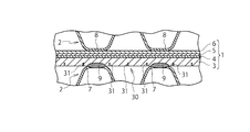
- FIG. 1 is a partial cross-sectional view of a solid oxide fuel cell according to a first embodiment of the present invention.
- FIG. 2 is an explanatory diagram illustrating a state where the cell according to the first embodiment is deformed.
- FIG. 3 is an explanatory diagram showing an example of a method for manufacturing a cell according to the first embodiment.
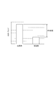
- FIG. 4 is a graph showing the evaluation results of the current collection resistance improvement degree.
- FIG. 5 is a partial cross-sectional view of a solid oxide fuel cell according to the second embodiment of the present invention.
- FIG. 6 is a partial cross-sectional view of a solid oxide fuel cell according to the third embodiment of the present invention.
- Solid oxide fuel cells are a type of fuel cell that is a device that converts scientific energy into electrical energy through an electrochemical reaction.
- the solid oxide fuel cell according to this embodiment includes a cell 1 as a power generation unit of the fuel cell, and a current collector that collects electrons from the fuel electrode 4 and the air electrode 6 of the cell 1. 2 and a housing (not shown) that accommodates the cell 1 and the current collector 2.
- the cell 1 has a three-layer structure in which a solid electrolyte 5 is sandwiched between a fuel electrode (anode electrode) 4 and an air electrode (cathode electrode) 6, and these fuel electrode 4 and solid electrolyte 5 and the air electrode 6 are laminated
- the metal support 3 is formed of a conductive material for the purpose of improving the output per unit area of the fuel cell, but gas permeability is also required to supply fuel gas or oxidant gas to the electrode. .
- the metal support 3 is formed of a porous metal substrate formed by sintering fine particles of high Cr stainless steel.
- the fuel electrode 4 for example, a noble metal such as nickel (Ni), cobalt (Co) and platinum (Pt) can be used. Further, a cermet of nickel (Ni) and a solid electrolyte can be used as the fuel electrode 4.
- the characteristics required for the fuel electrode 4 include a strong resistance to a reducing atmosphere, permeation of fuel gas, high electrical conductivity, and excellent catalytic action for converting hydrogen molecules into protons. .
- the air electrode 6 for example, metal powder particles such as silver (Ag) and platinum (Pt) can be used. Further, as the air electrode 6, oxide powder particles having a perovskite structure typified by lanthanum strontium manganite (LSM: LaSrMnO) and lanthanum strontium cobaltite (LSC: LaSrCoO) can also be used.
- LSM LaSrMnO
- LSC LaSrCoO
- the characteristics required for the air electrode 6 include resistance to oxidation, permeation of oxidant gas, high electrical conductivity, and excellent catalytic action for converting oxygen molecules into oxygen ions. It is done.
- oxygen gas molecules are decomposed into oxygen ions and electrons at the three-phase interface serving as an active point, and the oxygen ions are conducted to the fuel electrode 4 through the solid electrolyte 5. Further, in the fuel electrode 4, oxygen ions conducted from the solid electrolyte 5 react with fuel gas molecules at the three-phase interface which is also an active point, and electrons are emitted at that time.
- solid electrolyte 5 for example, stabilized zirconia in which yttria (Y2O3), neodymium (Nd2O3), samaria (Sm2O3), gadria (Gd2O3), scandia (Sc2O3), or the like can be used.
- Y2O3 yttria
- Nd2O3 neodymium
- Sm2O3 samaria
- Gd2O3 gadria
- Sc2O3 scandia
- CeO3 cerium oxide
- CeO2O2O2O3 cerium oxide
- oxide powder particles such as bismuth oxide (Bi2O3) and lanthanum gallium oxide (LaGaO3) can also be used.
- the current collector 2 is laminated so as to sandwich both surfaces of the cell 1 and is in contact with both surfaces of the cell 1.
- the current collector 2 further functions as a separator that partitions the fuel channel and the air channel with the cell 1.
- the current collector 2 is formed of a material (for example, Fe alloy or SUS) that has excellent oxidation resistance and conductivity.
- a portion corresponding to an active region contributing to power generation in the cell 1 is formed in a corrugated plate shape, and a contact portion 7 that contacts the metal support 3 and a contact portion that contacts the air electrode 6. 8 are alternately arranged.
- the current collector 2 is laminated in a symmetrical manner in which the contact portion 7 with the metal support 3 and the contact portion 8 with the air electrode 6 are in the same position with the cell 1 in between.
- the current collector 2 is fixed to the cell 1 by welding the contact portion 7 of the current collector 2 with the metal support 3.
- the weld 9 is shown as an ellipse.
- a solid oxide fuel cell having a stack structure is formed by laminating the aforementioned cell 1 and current collector 2 in multiple layers.
- the cell 1 is provided with the deformation induction unit 10, and the deformation induction unit 10 is configured to be more easily deformed than other portions of the cell 1. Then, when the cell 1 is deformed due to thermal expansion, the cell 1 is easily deformed with the deformation guiding portion 10 as a base point.
- the deformation induction part 10 is formed on the metal support 3 along the contact parts 7 and 8 with the cell 1 of the current collector 2, that is, the flow direction of the fuel flow path or the air flow path (the direction orthogonal to the plane of FIG. 1). ) Along the line.
- the deformation guiding unit 10 has a structure for facilitating the deformation of the cell 1 with the deformation guiding unit 10 as a base point, such as adding a crease in advance when the cell 1 is compared to origami.
- the deformation induction portion 10 is provided on the metal support 3 because it is generally difficult to provide the deformation induction portion 10 on the fuel electrode 4, the solid electrolyte 5, and the air electrode 6.
- the deformation induction part 10 is disposed on the metal support 3 in pairs with the contact part 7 of the current collector 2 with the metal support 3 interposed therebetween. Further, the deformation guide portion 10 is disposed at an intermediate portion between the contact portions 7 and 7 adjacent to each other on the metal support 3.
- the deformation induction part 10 of 1st embodiment is the thin film part 11 whose film thickness of the metal support body 3 is thinner than another part. Although not shown, the thin film portion 11 is intermittently disposed in the flow direction of the fuel flow path or the air flow path (direction perpendicular to the paper surface of FIG. 1).
- a plate-shaped metal support 3 is prepared by sintering fine particles of high Cr stainless steel (FIG. 3A).
- the thin film portion 11 is formed on either one of both surfaces of the metal support 3 by using grinding or etching (FIG. 3B). At this time, the thin film portion 11 is formed outside the contact portion that contacts the current collector 2, and another thin film portion 11 is formed between the contact portion that contacts the current collector 2 and the adjacent contact portion. Formed in the site.
- the fuel electrode 4, the solid electrolyte 5 and the air electrode 6 are formed on the surface of the metal support 3 opposite to the surface on which the thin film portion 11 is formed (FIG. 3 (c)).
- the solid electrolyte 5 was formed using a sputtering method
- the air electrode 6 was formed using a coating method.
- the separator pitch of the specimen is 4 mm, and the film thickness of the cell is 300 ⁇ m.
- the specimen has a stack structure in which cells and current collectors are stacked in multiple layers as shown in FIG. 1, and the outer edge surface of the cells is held by a casing.
- the specimens of the examples were provided with a deformation induction part (thin film part) on the metal support, and the test specimens of the comparative example were not provided with the deformation induction part (thin film part) on the metal support.
- the solid oxide fuel cell according to this embodiment includes a plate-like cell 1 having a structure in which a fuel electrode 4, a solid electrolyte 5, and an air electrode 6 are laminated on a metal support 3, and both surfaces of the cell 1.
- Current collectors 2 stacked so as to sandwich them.
- the current collector 2 is in contact with both surfaces of the cell 1.
- the cell 1 has a deformation guiding portion 10 that is more easily deformed than other portions of the cell 1.
- the cell 1 When the cell 1 is deformed due to thermal expansion, the cell 1 is likely to be deformed with the deformation guiding portion 10 as a base point, so that it is possible to suppress the current collector 2 and the cell 1 from being separated. Thereby, the contact property between the cell 1 and the current collector 2 at the time of rapid activation is improved, and an increase in current collecting resistance and a decrease in the output of the fuel cell can be suppressed.
- the deformation guiding part 10 extends linearly.
- the deformation guiding portion 10 extends linearly, when the cell 1 is deformed due to thermal expansion, the cell 1 is easily deformed with the deformation guiding portion 10 as a starting point as shown in FIG. Become. Therefore, when the cell 1 is deformed due to thermal expansion, it is possible to more reliably suppress the current collector 2 and the cell 1 from separating.
- the deformation induction part 10 is disposed in a pair with the contact part 7 between the current collector 2 and the cell 1 (metal support 3) interposed therebetween.
- the deformation induction unit 10 is disposed in a pair with the contact unit 7 interposed therebetween. It becomes easy to bend using the contact parts 7 and 8 with 1 as fulcrums. Therefore, when the cell 1 is deformed due to thermal expansion, it is possible to more reliably suppress the current collector 2 and the cell 1 from separating.
- the deformation guide portion 10 is disposed at an intermediate portion between the contact portions 7 and 7 adjacent to each other.
- the current collector is disposed as the deformation guide portion 10 is disposed at an intermediate portion between the contact portions 7 and 7 adjacent to each other. It becomes easy to bend using the contact parts 7 and 8 with the cell 1 of 2 as fulcrums. Therefore, when the cell 1 is deformed due to thermal expansion, it is possible to more reliably suppress the current collector 2 and the cell 1 from separating.
- the deformation induction part 10 is the thin film part 11 in which the film thickness of the metal support 3 is thinner than other parts.
- the deformation inducing part 10 is a thin film part 11 in which the film thickness of the metal support 3 is thinner than other parts, so that the cell 1 is easily deformed with the thin film part 11 as a starting point, as shown in FIG. Therefore, when the cell 1 is deformed due to thermal expansion, it is possible to more reliably suppress the current collector 2 and the cell 1 from separating.
- the cell 1 is provided with a deformation induction part 20, and the deformation induction part 20 is more than the other part of the cell 1. It is configured to be easily deformed, and when the cell 1 is deformed due to thermal expansion, the cell 1 is easily deformed with the deformation guiding portion 20 as a base point.
- the deformation guiding part 20 is formed on the metal support 3 along the contact parts 7 and 8 with the cell 1 of the current collector 2, that is, the flow direction of the fuel flow path or the air flow path (the direction perpendicular to the paper surface of FIG. 5). ) Along the line.
- the deformation guiding part 20 has a structure for facilitating the deformation of the cell 1 with the deformation guiding part 20 as a base point, such as attaching a crease in advance when the cell 1 is compared to origami.
- the deformation induction portion 20 is provided on the metal support 3 because it is generally difficult to provide the deformation induction portion 20 on the fuel electrode 4, the solid electrolyte 5, and the air electrode 6.
- the deformation induction part 20 is disposed on the metal support 3 in a pair with the contact part 7 of the current collector 2 with the metal support 3 interposed therebetween. Further, the deformation guide portion 20 is disposed at an intermediate portion between the contact portions 7 and 7 adjacent to each other on the metal support 3.
- the deformation induction part 20 of 2nd embodiment is the sparse structure part 21 whose porosity of the porous metal substrate which comprises the metal support body 3 is higher than another part.
- the sparse structure portion 21 is intermittently disposed in the flow direction of the fuel flow path or the air flow path (direction perpendicular to the paper surface of FIG. 5).
- the sparse structure portion 21 may be continuously arranged in the flow direction of the fuel flow path or the air flow path (direction perpendicular to the paper surface of FIG. 5).
- a plate-like metal support 3 is prepared by sintering fine particles of high Cr stainless steel.
- a groove is formed on either one of both surfaces of the metal support 3 using grinding or etching. At this time, the groove was formed in the outer part of the contact part in contact with the current collector 2, and another groove was formed in the intermediate part between the contact part in contact with the current collector 2 and the adjacent contact part. .
- high Cr stainless steel particles having a particle size larger than that of the metal support 3 are dispersed in a viscous organic binder solution to form a viscous slurry, and after filling the groove, sintering treatment is performed. Do.
- the sparse structure portion 21 was formed on the metal support 3 by such a process.
- the fuel electrode 4, the solid electrolyte 5, and the air electrode 6 are formed on the surface of the metal support 3 opposite to the surface on which the sparse structure portion 21 is formed.
- the solid electrolyte 5 was formed using a sputtering method
- the air electrode 6 was formed using a coating method.
- the current collector 2 is laminated.
- the deformation induction part 20 of 2nd embodiment is the sparse structure part 21 whose porosity of the porous metal substrate which comprises the metal support body 3 is higher than another part.
- the deformation induction part 20 is the sparse structure part 21 in which the porosity of the porous metal substrate constituting the metal support 3 is higher than that of the other part, the cell 1 is easily deformed with the sparse structure part 21 as a base point. . Therefore, it is possible to suppress the current collector 2 and the cell 1 from separating when the cell 1 is deformed due to thermal expansion. Moreover, since the deformation
- a solid oxide fuel cell according to a third embodiment of the present invention will be described with reference to FIG.
- the same parts as those in the first embodiment described above are denoted by the same reference numerals, and the description thereof is omitted.
- the cell 1 is provided with a deformation induction part 30, and the deformation induction part 30 is more than the other part of the cell 1. It is configured to be easily deformed, and when the cell 1 is deformed due to thermal expansion, the cell 1 is easily deformed with the deformation guiding portion 30 as a base point.
- the deformation guide 30 is formed on the metal support 3 along the contact portions 7 and 8 with the cell 1 of the current collector 2, that is, the flow direction of the fuel flow path or the air flow path (the direction orthogonal to the paper surface of FIG. 6). ) Along the line.
- the deformation guiding part 30 has a structure for facilitating the deformation of the cell 1 with the deformation guiding part 20 as a base point, such as attaching a crease in advance when the cell 1 is compared to origami.
- the deformation induction part 30 is provided on the metal support 3 because it is generally difficult to provide the deformation induction part 30 on the fuel electrode 4, the solid electrolyte 5 and the air electrode 6.
- the deformation induction part 30 is arrange
- the deformation induction part 30 of the third embodiment is a groove part 31 provided on the surface of the metal support 3. Although not shown, the groove 31 extends continuously in the flow direction of the fuel flow path or the air flow path (direction perpendicular to the paper surface of FIG. 6).
- the deformation guiding part 30 of the third embodiment is a groove part 31 provided on the surface of the metal support 3.
- the deformation induction part 30 is the groove part 31 provided on the surface of the metal support 3, so that the cell 1 is easily deformed with the groove part 31 as a base point. Therefore, it is possible to suppress the current collector 2 and the cell 1 from separating when the cell 1 is deformed due to thermal expansion.
- the fuel electrode 4 is laminated so as to be in contact with the metal support 3 among the three-layer laminated structure of the fuel electrode 4, the solid electrolyte 5, and the air electrode 6.
- the air electrode 6 may be laminated so as to be in contact with the metal support 3.
- the deformation induction part 10 thin film part 11 of 1st embodiment
- the deformation induction part 20 sinse structure part 21 of 2nd embodiment
- the deformation induction part 30 groove part 31 of 3rd embodiment mutually. It can be used in combination.
Landscapes
- Life Sciences & Earth Sciences (AREA)
- Engineering & Computer Science (AREA)
- Manufacturing & Machinery (AREA)
- Sustainable Development (AREA)
- Sustainable Energy (AREA)
- Chemical & Material Sciences (AREA)
- Chemical Kinetics & Catalysis (AREA)
- Electrochemistry (AREA)
- General Chemical & Material Sciences (AREA)
- Fuel Cell (AREA)
Abstract
Description
本発明の第一実施形態に係る固体酸化物型燃料電池を図1から図4に基づいて説明する。
供試体のセパレータピッチは4mm、セルの膜厚は300μmである。また、当然のことながら、供試体は、図1に示すような、セルおよび集電体が多層に積層されたスタック構造を有しており、セルの外縁面は筐体によって保持される。実施例の供試体は、金属支持体に変形誘導部(薄膜部)を設けたものとし、比較例の供試体は、金属支持体に変形誘導部(薄膜部)を設けないものとした。
急速昇温によって筐体とセルとの温度差が300℃になった時点で、集電抵抗の測定を開始した。急速昇温は、空気流路に加熱ガスを流すことにより行った。
実施例に係る供試体の集電抵抗値と、比較例に係る供試体の集電抵抗値との比較によって効果を確認した。図4に示すように、実施例に係る供試体の集電抵抗値は、比較例に係る供試体の集電抵抗値に対して15%低減したことが分かった。
集電抵抗測定試験後に、比較例に係る供試体を観察した結果、集電体の空気極との接触部が空気極から離れていることが確認され、最大250μmの隙間があることが分かった。これに対して、同様に、集電抵抗測定試験後に、実施例に係る供試体を観察した結果、集電体の空気極との接触部が空気極から離れることは確認されなかった(図2参照)。すなわち、集電体とセルとが離れるのを抑制することによって、集電抵抗の増加を抑制することが可能になった。
本発明の第二実施形態に係る固体酸化物型燃料電池を図5に基づいて説明する。なお、前述の第一実施形態と同一の部分は同一符号を付することによってその説明を省略する。
本発明の第三実施形態に係る固体酸化物型燃料電池を図6に基づいて説明する。なお、前述の第一実施形態と同一の部分は同一符号を付することによってその説明を省略する。
2 集電体
3 金属支持体
4 燃料極
5 固体電解質
6 空気極
7 接触部
8 接触部
10 変形誘導部
11 薄膜部
20 変形誘導部
21 疎構造部
30 変形誘導部
31 溝部
Claims (7)
- 金属支持体に燃料極と固体電解質と空気極とを積層した構造を有する板状のセルと、前記セルの両面を挟み込むように積層された集電体と、を備え、
前記集電体は、前記セルの両面にそれぞれ接触しており、
前記セルは、前記セルの他の部分よりも変形し易い変形誘導部を有する
ことを特徴とする固体酸化物型燃料電池。 - 前記変形誘導部は、線状に延在していることを特徴とする請求項1に記載の固体酸化物型燃料電池。
- 前記変形誘導部は、前記集電体の前記セルとの接触部を間に挟んで一対に配設されていることを特徴とする請求項2に記載の固体酸化物型燃料電池。
- 前記変形誘導部は、互いに隣接する前記接触部間の中間部位に配設されていることを特徴とする請求項3に記載の固体酸化物型燃料電池。
- 前記変形誘導部は、前記金属支持体の膜厚が他の部分よりも薄い薄膜部を有する請求項1から4のいずれか一項に記載の固体酸化物型燃料電池。
- 前記金属支持体は、多孔質金属基板により形成されており、
前記変形誘導部は、前記多孔質金属基板の気孔率が他の部分よりも高い疎構造部を有する請求項1から4のいずれか一項に記載の固体酸化物型燃料電池。 - 前記変形誘導部は、前記金属支持体の表面に設けられた溝部を有する請求項1から4のいずれか一項に記載の固体酸化物型燃料電池。
Priority Applications (7)
| Application Number | Priority Date | Filing Date | Title |
|---|---|---|---|
| CN201580080386.4A CN107615539B (zh) | 2015-05-25 | 2015-05-25 | 固体氧化物型燃料电池 |
| CA2987226A CA2987226C (en) | 2015-05-25 | 2015-05-25 | Solid oxide fuel cell |
| JP2017520094A JP6477870B2 (ja) | 2015-05-25 | 2015-05-25 | 固体酸化物型燃料電池 |
| US15/576,145 US10270118B2 (en) | 2015-05-25 | 2015-05-25 | Solid oxide fuel cell |
| EP15893255.8A EP3306719B1 (en) | 2015-05-25 | 2015-05-25 | Solid oxide fuel cell |
| BR112017025295-3A BR112017025295B1 (pt) | 2015-05-25 | 2015-05-25 | Célula a combustível de óxido sólido |
| PCT/JP2015/064903 WO2016189620A1 (ja) | 2015-05-25 | 2015-05-25 | 固体酸化物型燃料電池 |
Applications Claiming Priority (1)
| Application Number | Priority Date | Filing Date | Title |
|---|---|---|---|
| PCT/JP2015/064903 WO2016189620A1 (ja) | 2015-05-25 | 2015-05-25 | 固体酸化物型燃料電池 |
Publications (1)
| Publication Number | Publication Date |
|---|---|
| WO2016189620A1 true WO2016189620A1 (ja) | 2016-12-01 |
Family
ID=57393093
Family Applications (1)
| Application Number | Title | Priority Date | Filing Date |
|---|---|---|---|
| PCT/JP2015/064903 Ceased WO2016189620A1 (ja) | 2015-05-25 | 2015-05-25 | 固体酸化物型燃料電池 |
Country Status (7)
| Country | Link |
|---|---|
| US (1) | US10270118B2 (ja) |
| EP (1) | EP3306719B1 (ja) |
| JP (1) | JP6477870B2 (ja) |
| CN (1) | CN107615539B (ja) |
| BR (1) | BR112017025295B1 (ja) |
| CA (1) | CA2987226C (ja) |
| WO (1) | WO2016189620A1 (ja) |
Cited By (7)
| Publication number | Priority date | Publication date | Assignee | Title |
|---|---|---|---|---|
| JPWO2017104226A1 (ja) * | 2015-12-15 | 2018-09-27 | 日産自動車株式会社 | 燃料電池スタック |
| JP2019036445A (ja) * | 2017-08-10 | 2019-03-07 | 日産自動車株式会社 | 燃料電池スタック |
| WO2019106765A1 (ja) * | 2017-11-29 | 2019-06-06 | 日産自動車株式会社 | 燃料電池スタック |
| JP2019109963A (ja) * | 2017-12-15 | 2019-07-04 | 日産自動車株式会社 | 固体酸化物形燃料電池システム、固体酸化物形燃料電池システムにおける電解質膜の劣化回復装置、および固体酸化物形燃料電池における電解質膜の劣化回復方法 |
| JPWO2022219791A1 (ja) * | 2021-04-15 | 2022-10-20 | ||
| WO2023012979A1 (ja) * | 2021-08-05 | 2023-02-09 | 日産自動車株式会社 | 燃料電池セル及び燃料電池セルの製造方法 |
| KR20250019458A (ko) * | 2023-08-01 | 2025-02-10 | 한국에너지기술연구원 | 고체산화물 연료전지용 스택 |
Families Citing this family (2)
| Publication number | Priority date | Publication date | Assignee | Title |
|---|---|---|---|---|
| KR20220157519A (ko) * | 2016-03-18 | 2022-11-29 | 오사까 가스 가부시키가이샤 | 전기 화학 소자, 전기 화학 모듈, 전기 화학 장치 및 에너지 시스템 |
| KR102916276B1 (ko) * | 2020-09-02 | 2026-01-22 | 에스케이하이닉스 주식회사 | 3차원 구조의 반도체 장치 |
Citations (6)
| Publication number | Priority date | Publication date | Assignee | Title |
|---|---|---|---|---|
| JP2002505512A (ja) * | 1998-02-27 | 2002-02-19 | コーニング インコーポレイテッド | 可撓性無機電解質燃料電池構造 |
| JP2002319413A (ja) * | 2001-04-23 | 2002-10-31 | Nissan Motor Co Ltd | 固体電解質型燃料電池用セル板及びスタック |
| JP2003168448A (ja) * | 2001-11-30 | 2003-06-13 | Nissan Motor Co Ltd | 固体電解質型燃料電池用単セル |
| JP2004281172A (ja) * | 2003-03-14 | 2004-10-07 | Nissan Motor Co Ltd | 燃料電池用セル体及びその製造方法 |
| JP2008053107A (ja) * | 2006-08-25 | 2008-03-06 | Ngk Insulators Ltd | セラミックス薄板体を備えるデバイス |
| JP2013077450A (ja) * | 2011-09-30 | 2013-04-25 | Nippon Shokubai Co Ltd | 金属支持型固体酸化物形燃料電池用セル、それを用いた固体酸化物形燃料電池 |
Family Cites Families (10)
| Publication number | Priority date | Publication date | Assignee | Title |
|---|---|---|---|---|
| DE4234093A1 (de) * | 1992-10-09 | 1994-04-14 | Siemens Ag | Bauelement zum Einbau in eine verfahrenstechnische Einrichtung |
| DE4237602A1 (de) * | 1992-11-06 | 1994-05-11 | Siemens Ag | Hochtemperatur-Brennstoffzellen-Stapel und Verfahren zu seiner Herstellung |
| JP2001035514A (ja) | 1999-07-19 | 2001-02-09 | Tokyo Gas Co Ltd | 通電用金属薄板およびそれを用いた固体電解質燃料電池 |
| DE10044703B4 (de) * | 2000-09-09 | 2013-10-17 | Elringklinger Ag | Brennstoffzelleneinheit, Brennstoffzellenblockverbund und Verfahren zum Herstellen eines Brennstoffzellenblockverbunds |
| US6701585B2 (en) * | 2002-07-31 | 2004-03-09 | Chang-Wen Tsaur | Stop device for upper stops and a pull of a nylon zipper |
| US20040200187A1 (en) * | 2002-11-27 | 2004-10-14 | Warrier Sunil G. | Compliant, strain tolerant interconnects for solid oxide fuel cell stack |
| JP5224649B2 (ja) * | 2006-03-29 | 2013-07-03 | 日本碍子株式会社 | 導電性接続部材および固体酸化物形燃料電池 |
| RU2584849C2 (ru) * | 2010-12-07 | 2016-05-20 | Бревилл Пти Лимитед | Усовершенствованный кухонный комбайн |
| DK2728655T3 (en) * | 2011-06-28 | 2017-03-13 | Ngk Spark Plug Co | FAST OXIDE FUEL CELL AND CONNECTION PIPE |
| JP5330577B2 (ja) | 2011-08-09 | 2013-10-30 | 日本特殊陶業株式会社 | 燃料電池セル及び燃料電池スタック |
-
2015
- 2015-05-25 BR BR112017025295-3A patent/BR112017025295B1/pt not_active IP Right Cessation
- 2015-05-25 CA CA2987226A patent/CA2987226C/en active Active
- 2015-05-25 JP JP2017520094A patent/JP6477870B2/ja active Active
- 2015-05-25 EP EP15893255.8A patent/EP3306719B1/en active Active
- 2015-05-25 US US15/576,145 patent/US10270118B2/en active Active
- 2015-05-25 WO PCT/JP2015/064903 patent/WO2016189620A1/ja not_active Ceased
- 2015-05-25 CN CN201580080386.4A patent/CN107615539B/zh active Active
Patent Citations (6)
| Publication number | Priority date | Publication date | Assignee | Title |
|---|---|---|---|---|
| JP2002505512A (ja) * | 1998-02-27 | 2002-02-19 | コーニング インコーポレイテッド | 可撓性無機電解質燃料電池構造 |
| JP2002319413A (ja) * | 2001-04-23 | 2002-10-31 | Nissan Motor Co Ltd | 固体電解質型燃料電池用セル板及びスタック |
| JP2003168448A (ja) * | 2001-11-30 | 2003-06-13 | Nissan Motor Co Ltd | 固体電解質型燃料電池用単セル |
| JP2004281172A (ja) * | 2003-03-14 | 2004-10-07 | Nissan Motor Co Ltd | 燃料電池用セル体及びその製造方法 |
| JP2008053107A (ja) * | 2006-08-25 | 2008-03-06 | Ngk Insulators Ltd | セラミックス薄板体を備えるデバイス |
| JP2013077450A (ja) * | 2011-09-30 | 2013-04-25 | Nippon Shokubai Co Ltd | 金属支持型固体酸化物形燃料電池用セル、それを用いた固体酸化物形燃料電池 |
Non-Patent Citations (1)
| Title |
|---|
| See also references of EP3306719A4 * |
Cited By (14)
| Publication number | Priority date | Publication date | Assignee | Title |
|---|---|---|---|---|
| JPWO2017104226A1 (ja) * | 2015-12-15 | 2018-09-27 | 日産自動車株式会社 | 燃料電池スタック |
| JP2019036445A (ja) * | 2017-08-10 | 2019-03-07 | 日産自動車株式会社 | 燃料電池スタック |
| WO2019106765A1 (ja) * | 2017-11-29 | 2019-06-06 | 日産自動車株式会社 | 燃料電池スタック |
| JPWO2019106765A1 (ja) * | 2017-11-29 | 2020-10-22 | 日産自動車株式会社 | 燃料電池スタック |
| JP2019109963A (ja) * | 2017-12-15 | 2019-07-04 | 日産自動車株式会社 | 固体酸化物形燃料電池システム、固体酸化物形燃料電池システムにおける電解質膜の劣化回復装置、および固体酸化物形燃料電池における電解質膜の劣化回復方法 |
| JP7000835B2 (ja) | 2017-12-15 | 2022-01-19 | 日産自動車株式会社 | 固体酸化物形燃料電池システム、固体酸化物形燃料電池システムにおける電解質膜の劣化回復装置、および固体酸化物形燃料電池における電解質膜の劣化回復方法 |
| JPWO2022219791A1 (ja) * | 2021-04-15 | 2022-10-20 | ||
| WO2022219791A1 (ja) * | 2021-04-15 | 2022-10-20 | 日産自動車株式会社 | 燃料電池および燃料電池の製造方法 |
| JP7294522B2 (ja) | 2021-04-15 | 2023-06-20 | 日産自動車株式会社 | 燃料電池および燃料電池の製造方法 |
| WO2023012979A1 (ja) * | 2021-08-05 | 2023-02-09 | 日産自動車株式会社 | 燃料電池セル及び燃料電池セルの製造方法 |
| JPWO2023012979A1 (ja) * | 2021-08-05 | 2023-02-09 | ||
| JP7670138B2 (ja) | 2021-08-05 | 2025-04-30 | 日産自動車株式会社 | 燃料電池セル及び燃料電池セルの製造方法 |
| KR20250019458A (ko) * | 2023-08-01 | 2025-02-10 | 한국에너지기술연구원 | 고체산화물 연료전지용 스택 |
| KR102873042B1 (ko) * | 2023-08-01 | 2025-10-20 | 한국에너지기술연구원 | 고체산화물 연료전지용 스택 |
Also Published As
| Publication number | Publication date |
|---|---|
| BR112017025295A2 (pt) | 2018-08-07 |
| US20180166729A1 (en) | 2018-06-14 |
| CN107615539B (zh) | 2019-06-21 |
| BR112017025295B1 (pt) | 2022-08-30 |
| EP3306719A1 (en) | 2018-04-11 |
| CA2987226C (en) | 2019-07-02 |
| JP6477870B2 (ja) | 2019-03-06 |
| EP3306719A4 (en) | 2018-04-11 |
| CA2987226A1 (en) | 2016-12-01 |
| JPWO2016189620A1 (ja) | 2018-03-29 |
| EP3306719B1 (en) | 2019-04-03 |
| US10270118B2 (en) | 2019-04-23 |
| CN107615539A (zh) | 2018-01-19 |
Similar Documents
| Publication | Publication Date | Title |
|---|---|---|
| JP6477870B2 (ja) | 固体酸化物型燃料電池 | |
| US10256495B2 (en) | Fuel cell and fuel cell stack | |
| CN104081571B (zh) | 燃料电池 | |
| US20120178012A1 (en) | Sealing member for solid oxide fuel cell and solid oxide fuel cell employing the same | |
| JP6279519B2 (ja) | 燃料電池スタックおよび燃料電池単セル | |
| JP2014123544A (ja) | 固体酸化物形燃料電池及びインターコネクタの製作方法 | |
| KR101595225B1 (ko) | 금속 분리판과 공기극 집전체 간 접촉 저항이 저감된 고체산화물 연료전지 | |
| JP6435785B2 (ja) | 燃料電池用セパレータおよび燃料電池セルスタック | |
| JP2016039004A (ja) | 燃料電池 | |
| JP5588888B2 (ja) | 燃料電池スタックおよび燃料電池 | |
| JP5846936B2 (ja) | 燃料電池 | |
| US20130171539A1 (en) | Tubular solid oxide fuel cell module and method of manufacturing the same | |
| JP5667100B2 (ja) | 固体酸化物形燃料電池の製造方法 | |
| US20140178799A1 (en) | Solid oxide fuel cell and manufacturing method thereof | |
| JP4949737B2 (ja) | 固体酸化物形燃料電池セルスタックおよび固体酸化物形燃料電池 | |
| JP2016024951A (ja) | 固体酸化物形燃料電池 | |
| JP7643939B2 (ja) | 平板型固体酸化物形燃料電池 | |
| JP5727429B2 (ja) | セパレータ付燃料電池セル,および燃料電池 | |
| JP7552073B2 (ja) | 固体酸化物形燃料電池 | |
| WO2012133044A1 (ja) | 燃料電池 | |
| US20140178797A1 (en) | Solid oxide fuel cell | |
| WO2017002264A1 (ja) | 固体酸化物形燃料電池及びその製造方法 | |
| JP5999276B2 (ja) | 固体酸化物燃料電池 | |
| JP6734707B2 (ja) | 集電部材−電気化学反応単セル複合体および電気化学反応セルスタック | |
| JP2020042980A (ja) | 燃料電池 |
Legal Events
| Date | Code | Title | Description |
|---|---|---|---|
| 121 | Ep: the epo has been informed by wipo that ep was designated in this application |
Ref document number: 15893255 Country of ref document: EP Kind code of ref document: A1 |
|
| ENP | Entry into the national phase |
Ref document number: 2017520094 Country of ref document: JP Kind code of ref document: A |
|
| WWE | Wipo information: entry into national phase |
Ref document number: 15576145 Country of ref document: US |
|
| ENP | Entry into the national phase |
Ref document number: 2987226 Country of ref document: CA |
|
| NENP | Non-entry into the national phase |
Ref country code: DE |
|
| WWE | Wipo information: entry into national phase |
Ref document number: 2015893255 Country of ref document: EP |
|
| REG | Reference to national code |
Ref country code: BR Ref legal event code: B01A Ref document number: 112017025295 Country of ref document: BR |
|
| ENP | Entry into the national phase |
Ref document number: 112017025295 Country of ref document: BR Kind code of ref document: A2 Effective date: 20171124 |