WO2016189665A1 - 空気調和システムのリモートコントローラ - Google Patents
空気調和システムのリモートコントローラ Download PDFInfo
- Publication number
- WO2016189665A1 WO2016189665A1 PCT/JP2015/065132 JP2015065132W WO2016189665A1 WO 2016189665 A1 WO2016189665 A1 WO 2016189665A1 JP 2015065132 W JP2015065132 W JP 2015065132W WO 2016189665 A1 WO2016189665 A1 WO 2016189665A1
- Authority
- WO
- WIPO (PCT)
- Prior art keywords
- remote controller
- air conditioning
- conditioning system
- state diagnosis
- operation state
- Prior art date
- Legal status (The legal status is an assumption and is not a legal conclusion. Google has not performed a legal analysis and makes no representation as to the accuracy of the status listed.)
- Ceased
Links
Images



Classifications
-
- F—MECHANICAL ENGINEERING; LIGHTING; HEATING; WEAPONS; BLASTING
- F24—HEATING; RANGES; VENTILATING
- F24F—AIR-CONDITIONING; AIR-HUMIDIFICATION; VENTILATION; USE OF AIR CURRENTS FOR SCREENING
- F24F11/00—Control or safety arrangements
- F24F11/62—Control or safety arrangements characterised by the type of control or by internal processing, e.g. using fuzzy logic, adaptive control or estimation of values
-
- F—MECHANICAL ENGINEERING; LIGHTING; HEATING; WEAPONS; BLASTING
- F24—HEATING; RANGES; VENTILATING
- F24F—AIR-CONDITIONING; AIR-HUMIDIFICATION; VENTILATION; USE OF AIR CURRENTS FOR SCREENING
- F24F11/00—Control or safety arrangements
-
- F—MECHANICAL ENGINEERING; LIGHTING; HEATING; WEAPONS; BLASTING
- F24—HEATING; RANGES; VENTILATING
- F24F—AIR-CONDITIONING; AIR-HUMIDIFICATION; VENTILATION; USE OF AIR CURRENTS FOR SCREENING
- F24F11/00—Control or safety arrangements
- F24F11/30—Control or safety arrangements for purposes related to the operation of the system, e.g. for safety or monitoring
-
- F—MECHANICAL ENGINEERING; LIGHTING; HEATING; WEAPONS; BLASTING
- F24—HEATING; RANGES; VENTILATING
- F24F—AIR-CONDITIONING; AIR-HUMIDIFICATION; VENTILATION; USE OF AIR CURRENTS FOR SCREENING
- F24F11/00—Control or safety arrangements
- F24F11/30—Control or safety arrangements for purposes related to the operation of the system, e.g. for safety or monitoring
- F24F11/32—Responding to malfunctions or emergencies
- F24F11/39—Monitoring filter performance
-
- F—MECHANICAL ENGINEERING; LIGHTING; HEATING; WEAPONS; BLASTING
- F24—HEATING; RANGES; VENTILATING
- F24F—AIR-CONDITIONING; AIR-HUMIDIFICATION; VENTILATION; USE OF AIR CURRENTS FOR SCREENING
- F24F11/00—Control or safety arrangements
- F24F11/50—Control or safety arrangements characterised by user interfaces or communication
- F24F11/56—Remote control
-
- F—MECHANICAL ENGINEERING; LIGHTING; HEATING; WEAPONS; BLASTING
- F24—HEATING; RANGES; VENTILATING
- F24F—AIR-CONDITIONING; AIR-HUMIDIFICATION; VENTILATION; USE OF AIR CURRENTS FOR SCREENING
- F24F11/00—Control or safety arrangements
- F24F11/62—Control or safety arrangements characterised by the type of control or by internal processing, e.g. using fuzzy logic, adaptive control or estimation of values
- F24F11/63—Electronic processing
- F24F11/64—Electronic processing using pre-stored data
Definitions
- the present invention relates to a remote controller of an air conditioning system having an outdoor unit and an indoor unit.
- a maintenance inspection table based on the information on the air conditioner system's operating state collected by the remote controller, can be used by maintenance personnel, i.e., service personnel, to easily check the air conditioner system's operating condition when checking the air conditioner system.
- An air conditioning system that diagnoses the operating condition of the air conditioning system and displays the diagnosis result on a display screen has been put into practical use.
- Patent Document 1 which is an example of a technique for performing failure diagnosis by comparing a preset threshold value with a current state quantity, states that “a conventional refrigeration apparatus failure diagnosis method is set by accumulating past data. The state of the refrigeration system is grasped by comparing the current state quantity with a set threshold value or a preset threshold value, and in order to perform failure diagnosis in a refrigeration system equipped with a capacity-controllable compressor, ⁇ It was necessary to change the threshold every time the capacity changed or to set the threshold in advance for each refrigeration capacity. '' A refrigeration apparatus is disclosed that predicts an input value and compares the input value with an actually measured value, thereby enabling easy and accurate failure diagnosis even when the refrigeration capacity changes.
- the operation state diagnosis table for diagnosing the current operation state does not consider aged deterioration, and the same operation state diagnosis table is used without being changed from the start of use. . For this reason, it is possible to perform a highly accurate operation state diagnosis immediately after the start of use, but there is a problem that the accuracy of the operation state diagnosis is lowered when the air conditioning system deteriorates over time due to long-term use.
- the present invention has been made in view of the above, and an object of the present invention is to obtain a remote controller of an air conditioning system capable of performing an operation state diagnosis with high accuracy even after being used for many years.
- a remote controller of an air conditioning system is an air conditioning system remote controller including an outdoor unit and an indoor unit connected to the outdoor unit, A communication unit capable of two-way communication with the indoor unit by wire or wireless, and a memory that stores a plurality of operation state diagnosis tables for each operation mode, which is used at the time of maintenance and inspection of the air conditioning system.
- the table is selectively used according to an operation mode and an operation time of the air conditioning system.
- the remote controller of the air conditioning system according to the present invention has an effect that it is possible to obtain a remote controller of an air conditioning system that can perform an operation state diagnosis with high accuracy even after being used for many years.
- FIG. 3 is a block diagram illustrating an example of a configuration of a remote controller according to the first embodiment.
- the figure which shows an example of the item of the driving information which the remote controller which concerns on Embodiment 1 collects at the time of an inspection The figure which shows an example of the operating condition diagnostic table at the time of a cooling when the driving
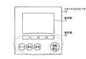
- FIG. FIG. 1 is a diagram showing an example of an external configuration of a remote controller according to Embodiment 1 of the present invention.
- a remote controller 10 shown in FIG. 1 includes a display unit 11 that displays an operation state represented by a set temperature and an operation mode, and an operation unit 12 that includes various operation buttons represented by an operation stop switching button and a menu button.
- the present invention is not limited to this, and an operation display unit may be provided instead of the display unit and the operation unit.
- the operation display unit can be realized by a touch panel.
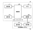
- FIG. 2 is a block diagram showing an example of the configuration of the remote controller according to Embodiment 1 of the present invention.
- the remote controller 10 shown in FIG. 2 includes a display unit 11, an operation unit 12, a control unit 20, a memory 21, and a communication unit 22, and the display unit 11, the operation unit 12, the memory 21, and the communication unit 22 are , Connected to the control unit 20.
- the control unit 20 is a processor that is realized by a microcomputer and controls the operation of the remote controller 10.
- the communication unit 22 is configured to perform wired or wireless bidirectional communication with the indoor unit 52 of the air conditioning system 50.
- the outdoor unit 51 and the indoor unit 52 constitute a part of the air conditioning system 50 controlled by the remote controller 10.
- the memory 21 includes a non-volatile memory and stores at least a plurality of operation state diagnosis tables used at the time of maintenance and inspection of the air conditioning system.
- the operating state diagnosis table is a table used for extracting necessary inspection items from the operating state of the air conditioning system.
- FIG. 3 is a diagram showing an example of the configuration of a remote controller according to Embodiment 1 of the present invention and an air conditioning system to which the remote controller is connected.
- the air conditioning system 50 connected to the remote controller 10 shown in FIG. 3 includes an outdoor unit 51, an indoor unit 52, an indoor / outdoor communication line 53a that connects the outdoor unit 51 and the indoor unit 52, an indoor unit 52, and a remote unit. And an indoor remote control communication line 53b for connecting to the controller 10.
- the indoor remote controller communication line 53b connects the indoor unit 52 and the remote controller 10 is illustrated here, the present invention is not limited to this, and the remote controller 10 may be a wireless remote controller.
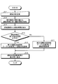
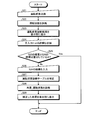
- FIG. 4 is a diagram showing an example of a flowchart of an operation state diagnosis by the remote controller according to Embodiment 1 of the present invention.
- the maintenance inspector or the user operates the operation unit 12 of the remote controller 10 using the operation state diagnosis table until the indoor unit operation time and the outdoor unit operation time reach the set time. By doing so, the operation state is checked (S11). Then, the remote controller 10 collects operation information including operation time from the outdoor unit 51 and the outdoor unit 52 via the indoor remote control communication line 53b (S12).
- the indoor unit operation time and the outdoor unit operation time are equal for convenience and may be simply referred to as “operation time”.
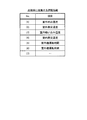
- FIG. 5 is a diagram showing an example of items of operation information collected at the time of inspection by the remote controller according to Embodiment 1 of the present invention.
- “outdoor discharge temperature”, “outdoor heat exchange temperature”, “indoor suction temperature”, “indoor heat exchange temperature”, “indoor unit operation time”, and “outdoor unit operation time” are listed as items.
- the numbers (1) to (6) are given in this order.
- (7) indicates that other items are included.
- the “outdoor discharge temperature” is the temperature of the air discharged by the outdoor unit
- the “indoor suction temperature” is the temperature of the air sucked by the indoor unit
- the “outdoor heat exchange temperature” is the heat of the outdoor unit. It is the temperature of the exchanger
- “indoor heat exchange temperature” is the temperature of the heat exchanger of the indoor unit.
- the remote controller 10 extracts the operation time that is the indoor unit operation time and the outdoor unit operation time from the collected operation information (S13). And the operation state diagnostic table which should be used is determined from the operation time which is indoor unit operation time and outdoor unit operation time. Specifically, it is determined whether or not the driving time is equal to or shorter than the first set time (S14), and the driving state diagnosis table is properly used according to the determination result.
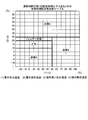
- FIG. 6 is a diagram illustrating an example of the cooling operation state diagnosis table stored in the memory of the remote controller according to Embodiment 1 of the present invention when the operation time is equal to or less than the first set time.
- FIG. 7 is a diagram illustrating an example of the heating operating state diagnosis table stored in the memory of the remote controller according to Embodiment 1 of the present invention when the operating time is equal to or shorter than the first set time.
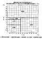
- FIG. 8 shows an operating condition diagnosis table during cooling when the operation time exceeds the first set time and is less than or equal to the second set time, which is stored in the memory of the remote controller according to Embodiment 1 of the present invention. It is a figure which shows an example.
- FIG. 8 shows an operating condition diagnosis table during cooling when the operation time exceeds the first set time and is less than or equal to the second set time, which is stored in the memory of the remote controller according to Embodiment 1 of the present invention. It is a figure which shows an example.
- the memory 21 of the remote controller 10 includes a plurality of operation state diagnosis tables during cooling and a plurality of operation state diagnosis tables during heating.
- each operation mode has a plurality of operation state diagnosis tables.
- the horizontal axis represents the difference obtained by subtracting the outdoor heat exchange temperature from the outdoor discharge temperature
- the vertical axis in FIGS. 6 and 8 represents the difference obtained by subtracting the indoor heat exchange temperature from the indoor suction temperature.
- the horizontal axis in FIGS. 7 and 9 is the difference obtained by subtracting the indoor heat exchange temperature from the outdoor discharge temperature
- the vertical axis in FIGS. 7 and 9 is the difference obtained by subtracting the indoor suction temperature from the indoor heat exchange temperature.
- the “normal” region indicates that the operation of the air conditioning system 50 is normal, and the “filter inspection” region should perform the filter inspection included in the air conditioning system 50.
- the areas “inspection A”, “inspection B”, and “inspection C” indicate that the air conditioning system 50 should be subjected to some predetermined inspection. As an example, when the difference obtained by subtracting the outdoor heat exchange temperature from the outdoor discharge temperature is 20, and the difference obtained by subtracting the indoor heat exchange temperature from the indoor suction temperature is 15, it is determined that the air conditioning system 50 is normal. Is done.
- the operation state diagnosis is performed using the first operation state diagnosis table (S15). That is, for the cooling operation, the operation state diagnosis is performed using the cooling operation state diagnosis table shown in FIG. 6, and for the heating operation, the operation state diagnosis is performed using the heating operation state diagnosis table shown in FIG.
- the operation state diagnosis is performed using the second operation state diagnosis table (S17). That is, for the cooling operation, the operation state diagnosis is performed using the cooling operation state diagnosis table shown in FIG. 8, and for the heating operation, the operation state diagnosis is performed using the heating operation state diagnosis table shown in FIG.
- the second operation state diagnosis table is an operation state diagnosis table when the operation time exceeds the first set time and is equal to or less than the second set time.
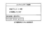
- FIG. 10 is a diagram illustrating an example of a display screen of a driving state diagnosis result during normal operation when the operation time is equal to or shorter than the first set time. In FIG. 10, it is displayed that the air conditioning system 50 is operating normally.
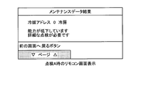
- FIG. 11 is a diagram illustrating an example of a display screen of a driving state diagnosis result when an abnormality occurs when the driving time is equal to or shorter than the first set time. In FIG. 11, it is displayed on the display screen that detailed inspection is necessary.
- the detailed inspection refers to an inspection performed manually by a maintenance inspector or a user with respect to an abnormal point displayed by the operation state diagnosis.
- the detailed inspection may be an inspection in which the filter is removed from the air conditioning system and visually confirmed when the operation state diagnosis is “filter inspection”.
- the air conditioning system includes a plurality of indoor units, and the result of maintenance data in the indoor unit of “refrigerant address 0” which is one of the plurality of indoor units is shown.
- the first operation state diagnosis table is shown in FIG.
- the operation state diagnosis is performed using the cooling operation state diagnosis table shown or the heating operation state diagnosis table shown in FIG. 7 and the operation state diagnosis is performed three years after the installation of the air conditioning system 50
- the second The operating state diagnosis is performed using the cooling operation state diagnosis table shown in FIG. 8 and the heating operation state diagnosis table shown in FIG.
- the present invention is not limited to this.
- the setting time may be further divided and three or more types of operation state diagnosis tables may be selectively used in each operation mode.
- a plurality of operation state diagnosis tables are stored in the memory of the remote controller, and these are used properly according to the operation mode and operation time of the air conditioning system. If it is determined whether or not the current operation time is less than or equal to the set operation time threshold, and a plurality of operation state diagnosis tables stored in the memory of the remote controller can be automatically switched based on the determination result Even after many years of use, it is possible to perform a driving state diagnosis with high accuracy.
- Embodiment 2 The operation state diagnosis table described in the first embodiment is created from the test data, and does not take into account the installation environment and operation conditions such as installation conditions or temperature conditions. Therefore, if the installation environment and operation status are different from the installation environment and operation status assumed at the time of test data acquisition, it is installed in the server room as an example, and when cooling is used throughout the year in winter It is not appropriate to use the operation state diagnosis table described in the first embodiment because it may deviate from the installation environment and operation state assumed at the time of obtaining test data. In the second embodiment, even when the installation environment and the operation status are different from the installation environment and the operation status assumed at the time of obtaining the test data, the operation diagnosis table is provided so that highly accurate operation status diagnosis is possible. The form which correct
- FIG. 12 is a diagram showing an example of a flowchart of the operation state diagnosis by the remote controller according to the second embodiment.
- the remote controller 10 performs an operation state check by operating the remote controller 10 (S21).
- the remote controller 10 diagnoses the operation state from the operation information collected along with the operation state inspection (S22), and displays the operation state diagnosis result on the display unit 11 (S23).
- the remote controller 10 determines the result of S22 and S24. It is determined whether the results are consistent (S25). If the result of determination in S25 is that the result of S22 matches the result of S24 (S25: Yes), the operation is terminated. If the result of S22 and the result of S24 do not match (S25: No), the remote controller 10 prompts the remote controller 10 to input the result of S24, and the result of S24 is input to the remote controller 10. (S26).
- the remote controller 10 corrects the operation state diagnosis table from the result of S24 input in S26 (S27), and again performs the operation state diagnosis in the same manner as S22 (S28). Thereafter, the remote controller 10 displays the corrected result on the display unit 11 (S29).
- the diagnosis result is “normal” in S22 and “normal” without any abnormality even if a detailed inspection is performed in S24, or the diagnosis result is “filter inspection” in S22. If the filter is actually clogged after a detailed inspection in S24, it can be said that the result of S22 is consistent with the result of S24.
- diagnosis result is “normal” in S22 and the filter is actually clogged after detailed inspection in S24, or the diagnosis result is “filter inspection” in S22 and detailed in S24. If it is “normal” without any abnormality even after the inspection, the result of S22 and the result of S24 are not consistent.
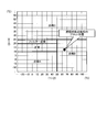
- FIG. 13 is a diagram showing an example of an operation state diagnosis table in which the operation state diagnosis results by the remote controller in S22 are plotted.
- the operation state diagnosis result deviates from the normal range, and an indication that inspection B should be performed is displayed.
- a detailed inspection in S24 revealed that the inspection B is actually unnecessary and normal. Therefore, the remote controller 10 corrects the operation state diagnosis table.
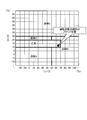
- FIG. 14 is a diagram illustrating an example of the operation state diagnosis table corrected in S27.
- the operation state diagnosis result is within the normal range by correcting the operation state diagnosis table.
- the operation state diagnosis table stored in the memory of the remote controller can be corrected according to the installation environment and the operation state.
- the configuration described in the above embodiment shows an example of the contents of the present invention, and can be combined with another known technique, and can be combined with other configurations without departing from the gist of the present invention. It is also possible to omit or change the part.
- 10 remote controller 11 display unit, 12 operation unit, 20 control unit, 21 memory, 22 communication unit, 50 air conditioning system, 51 outdoor unit, 52 indoor unit, 53a indoor outdoor communication line, 53b indoor remote control communication line.
Landscapes
- Engineering & Computer Science (AREA)
- Chemical & Material Sciences (AREA)
- Combustion & Propulsion (AREA)
- Mechanical Engineering (AREA)
- General Engineering & Computer Science (AREA)
- Physics & Mathematics (AREA)
- Fuzzy Systems (AREA)
- Mathematical Physics (AREA)
- Signal Processing (AREA)
- Air Conditioning Control Device (AREA)
Abstract
Description
図1は、本発明の実施の形態1に係るリモートコントローラの外観構成の一例を示す図である。図1に示すリモートコントローラ10は、設定温度及び運転モードに代表される運転状態を表示する表示部11と、運転停止切替ボタン及びメニューボタンに代表される各種操作ボタンを有する操作部12とを備える。ただし、本発明はこれに限定されず、表示部及び操作部に代えて操作表示部を備えていてもよい。なお、操作表示部は、タッチパネルにより実現することができる。
実施の形態1において説明した運転状態診断テーブルは、試験データから作成されるものであり、据付条件又は温度条件といった設置環境及び運転状況を考慮したものではない。そのため、設置環境及び運転状況が試験データ取得時に想定された設置環境及び運転状況と異なる場合、一例としてサーバールームに設置されて通年で冬場でも冷房を使用している状況である場合には、実施の形態1において説明した運転状態診断テーブルを用いることは試験データ取得時に想定された設置環境及び運転状況と乖離している場合があるため適切ではない。本実施の形態2においては、設置環境及び運転状況が、試験データ取得時に想定された設置環境及び運転状況と異なる場合であっても、精度の高い運転状態診断が可能となるように運転診断テーブルを補正する形態について説明する。
Claims (3)
- 室外機及び該室外機に接続された室内機を備える空気調和システムのリモートコントローラであって、
前記室内機と有線又は無線による双方向通信可能な通信部と、
前記空気調和システムの保守点検時に用いる、運転状態診断テーブルを動作モード毎に複数記憶したメモリとを備え、
複数の前記運転状態診断テーブルは、前記空気調和システムの動作モード及び運転時間に応じて使い分けられることを特徴とする空気調和システムのリモートコントローラ。 - 前記室内機及び前記室外機の現在の運転時間が、設定された運転時間のしきい値以下であるか否かを判定し、この判定の結果によって前記メモリに記憶された前記運転状態診断テーブルを自動で切替可能であることを特徴とする請求項1に記載の空気調和システムのリモートコントローラ。
- 前記運転状態診断テーブルが補正可能であることを特徴とする請求項1又は請求項2に記載の空気調和システムのリモートコントローラ。
Priority Applications (5)
| Application Number | Priority Date | Filing Date | Title |
|---|---|---|---|
| US15/554,787 US10365002B2 (en) | 2015-05-26 | 2015-05-26 | Remote controller of air-conditioning system |
| CN201580079038.5A CN108307650B (zh) | 2015-05-26 | 2015-05-26 | 空气调节系统的远程控制器 |
| EP15864299.1A EP3214384B1 (en) | 2015-05-26 | 2015-05-26 | Remote controller for air conditioning system |
| PCT/JP2015/065132 WO2016189665A1 (ja) | 2015-05-26 | 2015-05-26 | 空気調和システムのリモートコントローラ |
| JP2017520133A JP6355837B2 (ja) | 2015-05-26 | 2015-05-26 | 空気調和システムのリモートコントローラ |
Applications Claiming Priority (1)
| Application Number | Priority Date | Filing Date | Title |
|---|---|---|---|
| PCT/JP2015/065132 WO2016189665A1 (ja) | 2015-05-26 | 2015-05-26 | 空気調和システムのリモートコントローラ |
Publications (1)
| Publication Number | Publication Date |
|---|---|
| WO2016189665A1 true WO2016189665A1 (ja) | 2016-12-01 |
Family
ID=57393903
Family Applications (1)
| Application Number | Title | Priority Date | Filing Date |
|---|---|---|---|
| PCT/JP2015/065132 Ceased WO2016189665A1 (ja) | 2015-05-26 | 2015-05-26 | 空気調和システムのリモートコントローラ |
Country Status (5)
| Country | Link |
|---|---|
| US (1) | US10365002B2 (ja) |
| EP (1) | EP3214384B1 (ja) |
| JP (1) | JP6355837B2 (ja) |
| CN (1) | CN108307650B (ja) |
| WO (1) | WO2016189665A1 (ja) |
Cited By (1)
| Publication number | Priority date | Publication date | Assignee | Title |
|---|---|---|---|---|
| WO2018154768A1 (ja) * | 2017-02-27 | 2018-08-30 | 三菱電機株式会社 | 空気調和機 |
Families Citing this family (4)
| Publication number | Priority date | Publication date | Assignee | Title |
|---|---|---|---|---|
| US10401830B2 (en) * | 2015-08-14 | 2019-09-03 | Emerson Electric Co. | Remotely testing whether a climate control system controller is correctly installed |
| US11366461B2 (en) | 2015-08-14 | 2022-06-21 | Emerson Electric Co. | Remotely testing whether a climate control system controller is correctly installed |
| CN115406053A (zh) * | 2022-09-02 | 2022-11-29 | 珠海格力电器股份有限公司 | 空调器内外机通信方法、装置、空调器及存储介质 |
| CN119128434B (zh) * | 2024-08-26 | 2025-05-16 | 北京海淀中京工程设计软件技术有限公司 | 一种基于可视化的石油化工设备运行监管系统及方法 |
Citations (4)
| Publication number | Priority date | Publication date | Assignee | Title |
|---|---|---|---|---|
| JP2003161495A (ja) * | 2001-11-21 | 2003-06-06 | Yamatake Corp | 空気調和機の異常検出装置、異常検出方法及びプログラム |
| JP2008057921A (ja) | 2006-09-01 | 2008-03-13 | Sanyo Electric Co Ltd | 冷凍装置 |
| JP2010210121A (ja) * | 2009-03-09 | 2010-09-24 | Mitsubishi Electric Corp | 空気調和装置 |
| JP2013174385A (ja) * | 2012-02-24 | 2013-09-05 | Mitsubishi Electric Corp | 空気調和機システムおよびリモコン |
Family Cites Families (9)
| Publication number | Priority date | Publication date | Assignee | Title |
|---|---|---|---|---|
| JPH0776724B2 (ja) * | 1988-02-18 | 1995-08-16 | 富士重工業株式会社 | 車輌診断装置 |
| JPH04347444A (ja) * | 1991-05-23 | 1992-12-02 | Toshiba Corp | 空気調和機の室外ユニット情報表示システム |
| JP2000065415A (ja) * | 1998-08-19 | 2000-03-03 | Sanyo Electric Co Ltd | 空気調和機 |
| JP2003172567A (ja) | 2001-04-24 | 2003-06-20 | Fuji Electric Co Ltd | 故障診断方法、故障診断装置、店舗内機器管理システム、及び記録媒体 |
| JP2003316423A (ja) * | 2002-04-25 | 2003-11-07 | Daikin Ind Ltd | 設備機器診断装置及び設備機器診断システム |
| JP5084502B2 (ja) * | 2006-09-20 | 2012-11-28 | 三菱電機株式会社 | 空気調和システム |
| AU2012200300B2 (en) * | 2011-01-20 | 2015-08-20 | Fujitsu General Limited | Air conditioner |
| JP5425282B1 (ja) | 2012-08-31 | 2014-02-26 | 三菱電機株式会社 | 遠隔制御システム、システムコントローラ及びプログラム |
| CN104566838B (zh) * | 2015-02-02 | 2017-11-14 | 珠海格力电器股份有限公司 | 空调器的故障检测方法和装置 |
-
2015
- 2015-05-26 US US15/554,787 patent/US10365002B2/en active Active
- 2015-05-26 JP JP2017520133A patent/JP6355837B2/ja not_active Expired - Fee Related
- 2015-05-26 CN CN201580079038.5A patent/CN108307650B/zh not_active Expired - Fee Related
- 2015-05-26 WO PCT/JP2015/065132 patent/WO2016189665A1/ja not_active Ceased
- 2015-05-26 EP EP15864299.1A patent/EP3214384B1/en not_active Not-in-force
Patent Citations (4)
| Publication number | Priority date | Publication date | Assignee | Title |
|---|---|---|---|---|
| JP2003161495A (ja) * | 2001-11-21 | 2003-06-06 | Yamatake Corp | 空気調和機の異常検出装置、異常検出方法及びプログラム |
| JP2008057921A (ja) | 2006-09-01 | 2008-03-13 | Sanyo Electric Co Ltd | 冷凍装置 |
| JP2010210121A (ja) * | 2009-03-09 | 2010-09-24 | Mitsubishi Electric Corp | 空気調和装置 |
| JP2013174385A (ja) * | 2012-02-24 | 2013-09-05 | Mitsubishi Electric Corp | 空気調和機システムおよびリモコン |
Non-Patent Citations (1)
| Title |
|---|
| See also references of EP3214384A4 |
Cited By (2)
| Publication number | Priority date | Publication date | Assignee | Title |
|---|---|---|---|---|
| WO2018154768A1 (ja) * | 2017-02-27 | 2018-08-30 | 三菱電機株式会社 | 空気調和機 |
| JPWO2018154768A1 (ja) * | 2017-02-27 | 2019-11-07 | 三菱電機株式会社 | 空気調和機 |
Also Published As
| Publication number | Publication date |
|---|---|
| JP6355837B2 (ja) | 2018-07-11 |
| US20180038608A1 (en) | 2018-02-08 |
| EP3214384B1 (en) | 2020-11-18 |
| CN108307650A (zh) | 2018-07-20 |
| EP3214384A4 (en) | 2017-09-06 |
| EP3214384A1 (en) | 2017-09-06 |
| JPWO2016189665A1 (ja) | 2017-08-10 |
| US10365002B2 (en) | 2019-07-30 |
| CN108307650B (zh) | 2020-09-18 |
Similar Documents
| Publication | Publication Date | Title |
|---|---|---|
| JP6355837B2 (ja) | 空気調和システムのリモートコントローラ | |
| US7308384B2 (en) | Ordered record of system-wide fault in an HVAC system | |
| US20170010014A1 (en) | Air conditioner test operation application, and air conditioner test operation system | |
| US10823440B2 (en) | Systems and methods for interactive HVAC maintenance interface | |
| US7500368B2 (en) | System and method for verifying proper refrigerant and airflow for air conditioners and heat pumps in cooling mode | |
| KR100640851B1 (ko) | 멀티 에어컨 시스템의 상태 모니터링 장치 및 그 방법 | |
| US20110071722A1 (en) | Air conditioner for vehicle, and system and method of vehicle air-conditioning management | |
| CN104034998B (zh) | 一种定频空调内外机连接线接错的诊断方法及诊断系统 | |
| KR101245023B1 (ko) | 공기 조화기의 제어방법 | |
| US9909776B2 (en) | Air conditioner | |
| CN108954670B (zh) | 一种空调器的故障预判方法、控制系统及空调器 | |
| ES2918206T3 (es) | Sistema de diagnóstico de averías | |
| JP2019060539A (ja) | 空気調和装置 | |
| CN105757908B (zh) | 空调器控制方法及装置 | |
| US11913659B2 (en) | Systems and methods for monitoring operation of an HVAC system | |
| JP6141217B2 (ja) | 圧縮機劣化診断装置及び圧縮機劣化診断方法 | |
| KR101871724B1 (ko) | 공기조화장치의 제어방법 | |
| JP6147087B2 (ja) | 車両用空気調和装置の故障診断装置 | |
| US8001230B2 (en) | Group management apparatus and group management system | |
| JP3102208B2 (ja) | 空気調和装置の運転制御装置 | |
| CN107023935A (zh) | 空调系统及其停机控制方法 | |
| JP6625196B2 (ja) | 空調システム | |
| JP2005282903A (ja) | 空気調和機 | |
| JP6852850B2 (ja) | 空調機の診断方法及び診断装置 | |
| JP2006090614A (ja) | 空気調和機 |
Legal Events
| Date | Code | Title | Description |
|---|---|---|---|
| REEP | Request for entry into the european phase |
Ref document number: 2015864299 Country of ref document: EP |
|
| WWE | Wipo information: entry into national phase |
Ref document number: 2015864299 Country of ref document: EP |
|
| 121 | Ep: the epo has been informed by wipo that ep was designated in this application |
Ref document number: 15864299 Country of ref document: EP Kind code of ref document: A1 |
|
| ENP | Entry into the national phase |
Ref document number: 2017520133 Country of ref document: JP Kind code of ref document: A |
|
| WWE | Wipo information: entry into national phase |
Ref document number: 15554787 Country of ref document: US |
|
| NENP | Non-entry into the national phase |
Ref country code: DE |