WO2016189680A1 - 排熱回収装置 - Google Patents
排熱回収装置 Download PDFInfo
- Publication number
- WO2016189680A1 WO2016189680A1 PCT/JP2015/065202 JP2015065202W WO2016189680A1 WO 2016189680 A1 WO2016189680 A1 WO 2016189680A1 JP 2015065202 W JP2015065202 W JP 2015065202W WO 2016189680 A1 WO2016189680 A1 WO 2016189680A1
- Authority
- WO
- WIPO (PCT)
- Prior art keywords
- exhaust
- heat recovery
- vibration system
- internal combustion
- combustion engine
- Prior art date
- Legal status (The legal status is an assumption and is not a legal conclusion. Google has not performed a legal analysis and makes no representation as to the accuracy of the status listed.)
- Ceased
Links
Images



Classifications
-
- F—MECHANICAL ENGINEERING; LIGHTING; HEATING; WEAPONS; BLASTING
- F01—MACHINES OR ENGINES IN GENERAL; ENGINE PLANTS IN GENERAL; STEAM ENGINES
- F01N—GAS-FLOW SILENCERS OR EXHAUST APPARATUS FOR MACHINES OR ENGINES IN GENERAL; GAS-FLOW SILENCERS OR EXHAUST APPARATUS FOR INTERNAL-COMBUSTION ENGINES
- F01N5/00—Exhaust or silencing apparatus combined or associated with devices profiting by exhaust energy
- F01N5/02—Exhaust or silencing apparatus combined or associated with devices profiting by exhaust energy the devices using heat
-
- B—PERFORMING OPERATIONS; TRANSPORTING
- B60—VEHICLES IN GENERAL
- B60K—ARRANGEMENT OR MOUNTING OF PROPULSION UNITS OR OF TRANSMISSIONS IN VEHICLES; ARRANGEMENT OR MOUNTING OF PLURAL DIVERSE PRIME-MOVERS IN VEHICLES; AUXILIARY DRIVES FOR VEHICLES; INSTRUMENTATION OR DASHBOARDS FOR VEHICLES; ARRANGEMENTS IN CONNECTION WITH COOLING, AIR INTAKE, GAS EXHAUST OR FUEL SUPPLY OF PROPULSION UNITS IN VEHICLES
- B60K13/00—Arrangement in connection with combustion air intake or gas exhaust of propulsion units
- B60K13/04—Arrangement in connection with combustion air intake or gas exhaust of propulsion units concerning exhaust
-
- F—MECHANICAL ENGINEERING; LIGHTING; HEATING; WEAPONS; BLASTING
- F01—MACHINES OR ENGINES IN GENERAL; ENGINE PLANTS IN GENERAL; STEAM ENGINES
- F01N—GAS-FLOW SILENCERS OR EXHAUST APPARATUS FOR MACHINES OR ENGINES IN GENERAL; GAS-FLOW SILENCERS OR EXHAUST APPARATUS FOR INTERNAL-COMBUSTION ENGINES
- F01N13/00—Exhaust or silencing apparatus characterised by constructional features
- F01N13/18—Construction facilitating manufacture, assembly, or disassembly
- F01N13/1805—Fixing exhaust manifolds, exhaust pipes or pipe sections to each other, to engine or to vehicle body
- F01N13/1811—Fixing exhaust manifolds, exhaust pipes or pipe sections to each other, to engine or to vehicle body with means permitting relative movement, e.g. compensation of thermal expansion or vibration
-
- F—MECHANICAL ENGINEERING; LIGHTING; HEATING; WEAPONS; BLASTING
- F01—MACHINES OR ENGINES IN GENERAL; ENGINE PLANTS IN GENERAL; STEAM ENGINES
- F01N—GAS-FLOW SILENCERS OR EXHAUST APPARATUS FOR MACHINES OR ENGINES IN GENERAL; GAS-FLOW SILENCERS OR EXHAUST APPARATUS FOR INTERNAL-COMBUSTION ENGINES
- F01N3/00—Exhaust or silencing apparatus having means for purifying, rendering innocuous, or otherwise treating exhaust
- F01N3/08—Exhaust or silencing apparatus having means for purifying, rendering innocuous, or otherwise treating exhaust for rendering innocuous
- F01N3/10—Exhaust or silencing apparatus having means for purifying, rendering innocuous, or otherwise treating exhaust for rendering innocuous by thermal or catalytic conversion of noxious components of exhaust
-
- F—MECHANICAL ENGINEERING; LIGHTING; HEATING; WEAPONS; BLASTING
- F02—COMBUSTION ENGINES; HOT-GAS OR COMBUSTION-PRODUCT ENGINE PLANTS
- F02M—SUPPLYING COMBUSTION ENGINES IN GENERAL WITH COMBUSTIBLE MIXTURES OR CONSTITUENTS THEREOF
- F02M26/00—Engine-pertinent apparatus for adding exhaust gases to combustion-air, main fuel or fuel-air mixture, e.g. by exhaust gas recirculation [EGR] systems
- F02M26/13—Arrangement or layout of EGR passages, e.g. in relation to specific engine parts or for incorporation of accessories
- F02M26/22—Arrangement or layout of EGR passages, e.g. in relation to specific engine parts or for incorporation of accessories with coolers in the recirculation passage
- F02M26/29—Constructional details of the coolers, e.g. pipes, plates, ribs, insulation or materials
- F02M26/30—Connections of coolers to other devices, e.g. to valves, heaters, compressors or filters; Coolers characterised by their location on the engine
-
- F—MECHANICAL ENGINEERING; LIGHTING; HEATING; WEAPONS; BLASTING
- F02—COMBUSTION ENGINES; HOT-GAS OR COMBUSTION-PRODUCT ENGINE PLANTS
- F02N—STARTING OF COMBUSTION ENGINES; STARTING AIDS FOR SUCH ENGINES, NOT OTHERWISE PROVIDED FOR
- F02N19/00—Starting aids for combustion engines, not otherwise provided for
- F02N19/02—Aiding engine start by thermal means, e.g. using lighted wicks
- F02N19/04—Aiding engine start by thermal means, e.g. using lighted wicks by heating of fluids used in engines
- F02N19/10—Aiding engine start by thermal means, e.g. using lighted wicks by heating of fluids used in engines by heating of engine coolants
-
- B—PERFORMING OPERATIONS; TRANSPORTING
- B60—VEHICLES IN GENERAL
- B60K—ARRANGEMENT OR MOUNTING OF PROPULSION UNITS OR OF TRANSMISSIONS IN VEHICLES; ARRANGEMENT OR MOUNTING OF PLURAL DIVERSE PRIME-MOVERS IN VEHICLES; AUXILIARY DRIVES FOR VEHICLES; INSTRUMENTATION OR DASHBOARDS FOR VEHICLES; ARRANGEMENTS IN CONNECTION WITH COOLING, AIR INTAKE, GAS EXHAUST OR FUEL SUPPLY OF PROPULSION UNITS IN VEHICLES
- B60K5/00—Arrangement or mounting of internal-combustion or jet-propulsion units
- B60K5/12—Arrangement of engine supports
- B60K5/1208—Resilient supports
-
- B—PERFORMING OPERATIONS; TRANSPORTING
- B60—VEHICLES IN GENERAL
- B60Y—INDEXING SCHEME RELATING TO ASPECTS CROSS-CUTTING VEHICLE TECHNOLOGY
- B60Y2400/00—Special features of vehicle units
- B60Y2400/48—Vibration dampers, e.g. dual mass flywheels
-
- F—MECHANICAL ENGINEERING; LIGHTING; HEATING; WEAPONS; BLASTING
- F01—MACHINES OR ENGINES IN GENERAL; ENGINE PLANTS IN GENERAL; STEAM ENGINES
- F01N—GAS-FLOW SILENCERS OR EXHAUST APPARATUS FOR MACHINES OR ENGINES IN GENERAL; GAS-FLOW SILENCERS OR EXHAUST APPARATUS FOR INTERNAL-COMBUSTION ENGINES
- F01N2240/00—Combination or association of two or more different exhaust treating devices, or of at least one such device with an auxiliary device, not covered by indexing codes F01N2230/00 or F01N2250/00, one of the devices being
-
- F—MECHANICAL ENGINEERING; LIGHTING; HEATING; WEAPONS; BLASTING
- F01—MACHINES OR ENGINES IN GENERAL; ENGINE PLANTS IN GENERAL; STEAM ENGINES
- F01N—GAS-FLOW SILENCERS OR EXHAUST APPARATUS FOR MACHINES OR ENGINES IN GENERAL; GAS-FLOW SILENCERS OR EXHAUST APPARATUS FOR INTERNAL-COMBUSTION ENGINES
- F01N2240/00—Combination or association of two or more different exhaust treating devices, or of at least one such device with an auxiliary device, not covered by indexing codes F01N2230/00 or F01N2250/00, one of the devices being
- F01N2240/02—Combination or association of two or more different exhaust treating devices, or of at least one such device with an auxiliary device, not covered by indexing codes F01N2230/00 or F01N2250/00, one of the devices being a heat exchanger
-
- F—MECHANICAL ENGINEERING; LIGHTING; HEATING; WEAPONS; BLASTING
- F02—COMBUSTION ENGINES; HOT-GAS OR COMBUSTION-PRODUCT ENGINE PLANTS
- F02M—SUPPLYING COMBUSTION ENGINES IN GENERAL WITH COMBUSTIBLE MIXTURES OR CONSTITUENTS THEREOF
- F02M26/00—Engine-pertinent apparatus for adding exhaust gases to combustion-air, main fuel or fuel-air mixture, e.g. by exhaust gas recirculation [EGR] systems
- F02M26/12—Engine-pertinent apparatus for adding exhaust gases to combustion-air, main fuel or fuel-air mixture, e.g. by exhaust gas recirculation [EGR] systems characterised by means for attaching parts of an EGR system to each other or to engine parts
-
- F—MECHANICAL ENGINEERING; LIGHTING; HEATING; WEAPONS; BLASTING
- F02—COMBUSTION ENGINES; HOT-GAS OR COMBUSTION-PRODUCT ENGINE PLANTS
- F02M—SUPPLYING COMBUSTION ENGINES IN GENERAL WITH COMBUSTIBLE MIXTURES OR CONSTITUENTS THEREOF
- F02M26/00—Engine-pertinent apparatus for adding exhaust gases to combustion-air, main fuel or fuel-air mixture, e.g. by exhaust gas recirculation [EGR] systems
- F02M26/13—Arrangement or layout of EGR passages, e.g. in relation to specific engine parts or for incorporation of accessories
- F02M26/22—Arrangement or layout of EGR passages, e.g. in relation to specific engine parts or for incorporation of accessories with coolers in the recirculation passage
- F02M26/23—Layout, e.g. schematics
- F02M26/28—Layout, e.g. schematics with liquid-cooled heat exchangers
-
- Y—GENERAL TAGGING OF NEW TECHNOLOGICAL DEVELOPMENTS; GENERAL TAGGING OF CROSS-SECTIONAL TECHNOLOGIES SPANNING OVER SEVERAL SECTIONS OF THE IPC; TECHNICAL SUBJECTS COVERED BY FORMER USPC CROSS-REFERENCE ART COLLECTIONS [XRACs] AND DIGESTS
- Y02—TECHNOLOGIES OR APPLICATIONS FOR MITIGATION OR ADAPTATION AGAINST CLIMATE CHANGE
- Y02T—CLIMATE CHANGE MITIGATION TECHNOLOGIES RELATED TO TRANSPORTATION
- Y02T10/00—Road transport of goods or passengers
- Y02T10/10—Internal combustion engine [ICE] based vehicles
- Y02T10/12—Improving ICE efficiencies
Definitions
- the present invention relates to an exhaust heat recovery device that recovers heat of exhaust gas of an internal combustion engine to a heat medium circulating through the internal combustion engine by an exhaust heat exchanger interposed in an exhaust passage of the internal combustion engine.
- JP2008-27485A discloses a device having a heat medium circuit in which a heat medium discharged from an internal combustion engine is first sent to a heater core, and the heat medium that has passed through the heater core flows into the heat exchanger as it is. ing.
- an internal combustion engine is mounted on a vehicle body via an elastic member to form an engine vibration system
- an exhaust passage is mounted on the vehicle body via an elastic member to form an exhaust vibration system.
- the heater core is generally fixedly supported near the engine compartment of the vehicle body, it is included in the vehicle body vibration system.
- the exhaust heat recovery apparatus disclosed in the above document has a heat medium circuit that connects parts of different vibration systems with heat medium pipes. For this reason, it is necessary to absorb the relative displacement of each vibration system during vehicle operation by the heat medium pipe.
- a configuration is known in which a flexible hose formed of, for example, rubber or silicon is used as a joint for connecting metal pipes.
- the relative displacement increases as in the heater core and the exhaust heat exchanger in the above document
- the length of the hose necessary to absorb the vibration increases, leading to a decrease in the layout of the heat medium piping and an increase in cost.
- the heat resistance temperature of the hose is lower than that of metal pipes, it is necessary to take measures against heat insulation from the exhaust passage or the like. For this reason, when the hose length increases, not only the material cost but also the cost for heat shield measures increase.
- an object of the present invention is to provide an exhaust heat recovery apparatus having a heat medium flow path that does not cause deterioration in layout performance of the piping and increase in cost.
- an exhaust heat recovery device that recovers heat of exhaust gas of a vehicle internal combustion engine, and an inflow side piping and an exhaust side piping that connect the internal combustion engine and the exhaust heat recovery device.
- a configured exhaust heat recovery device is provided.
- the inflow side piping and the exhaust side piping of the exhaust heat recovery apparatus are mounted only on components included in the non-vehicle body vibration system supported by the vehicle body via an elastic body.
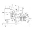
- FIG. 1 is a configuration diagram of an exhaust heat recovery apparatus according to the first embodiment.
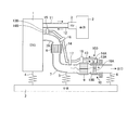
- FIG. 2 is a configuration diagram of an exhaust heat recovery apparatus as a comparative example.
- FIG. 3 is a configuration diagram of an exhaust heat recovery apparatus as another example of the first embodiment.
- FIG. 4 is a configuration diagram of the exhaust heat recovery apparatus according to the second embodiment.
- FIG. 5 is a configuration diagram of the exhaust heat recovery apparatus according to the third embodiment.
- FIG. 1 is a diagram schematically showing the configuration of the exhaust heat recovery apparatus 100.
- An internal combustion engine (hereinafter also referred to as “engine”) 1 is mounted on a vehicle body 2 via an engine mount 4 having elasticity. Thereby, an engine vibration system including the engine 1 and the engine mount 4 is formed.
- the engine vibration system includes parts associated with the engine 1 such as an alternator and a throttle body (not shown).
- the exhaust passage 7 has one end connected to the engine 1 and is mounted on the vehicle body via exhaust mounts 5 and 6 having elasticity. Thus, an exhaust vibration system including the exhaust passage 7 and the exhaust mounts 5 and 6 is formed.
- the “exhaust passage 7” includes the exhaust manifold 7A.
- a manifold catalyst 8, an underfloor catalyst 9, and an exhaust heat exchanger 10 are interposed from the exhaust manifold 7A side to the outlet side.
- the manifold catalyst 8 is disposed immediately downstream of the exhaust manifold 7A. That is, the manifold catalyst 8 is disposed in the engine compartment.
- One underfloor catalyst 9 is disposed on the lower surface of the vehicle body 2.
- the exhaust passage 7 is schematically shown above the vehicle body 2 for simplicity.
- the exhaust heat exchanger 10 includes a lattice-shaped or honeycomb-shaped heat receiving member 10A disposed in the flow path of the exhaust passage 7, and an annular member 10B that includes a heat medium flow path therein and contacts the outer periphery of the heat receiving member 10A. Consists of.
- the heat receiving member 10 ⁇ / b> A is made of, for example, a metal material and is heated by the heat of the exhaust gas flowing through the exhaust passage 7.
- the heat receiving member 10A is heated, the temperature of the annular member 10B in contact with the outer periphery of the heat receiving member 10A also rises, and heat exchange is performed with the heat medium circulating inside.
- the heat medium that circulates inside the annular member 10 ⁇ / b> B is the coolant of the engine 1.
- the coolant is supplied from the engine 1 to the annular member 10B via the inflow side pipe 14, exchanges heat in the flow path in the annular member 10B, and then returned to the engine 1 via the discharge side pipe 13.
- the inflow side pipe 14 is made of a metal material, and has one end of a heat medium supply port 14A connected to the annular member 10B and the other end of a heat medium outlet 14B connected to the engine 1.
- the inflow side piping 14 is mounted on an engine vibration system component and an exhaust vibration system component.
- the first mount 15 is mounted on the engine 1 included in the engine vibration system
- the second mount 16, the third mount 17, and the fourth mount are disposed in the exhaust passage 7 included in the exhaust vibration system. It is mounted via the mount 18.
- the portion from the heat medium supply port 14A to the first mount 15 becomes the first inflow side piping portion
- the portion from the first mount 15 to the heat medium outlet port 14B becomes the first inflow side piping portion.
- a hose 19 as a vibration absorbing portion is interposed between the first mount 15 and the second mount 16 in the inflow side pipe 14.
- the hose 19 is made of an elastic material such as rubber or silicon.
- the discharge side pipe 13 is made of a metal material, one end of which is connected to the annular member 10 ⁇ / b> B, a heat medium discharge port 13 ⁇ / b> A, and the other end is connected to the engine 1. 13B.
- the discharge side pipe 13 is mounted on the engine 1 and the exhaust passage 7 via the first mount 15 to the fourth mount 18.
- a portion from the heat medium discharge port 13A to the first mount 15 is a first discharge side piping portion
- a portion from the first mount 15 to the heat medium return port 13B is a second discharge side piping portion.
- a hose 20 is interposed in the discharge side pipe 13 as well as the inflow side pipe 14.
- the first mount 15 to the fourth mount 18 are made of a material having excellent heat resistance such as metal or heat-resistant resin, and fix and support the inflow side pipe 14 and the outflow side pipe 13.
- each mount 15-18 fixes and supports the inflow side pipe 14 and the discharge side pipe 13, but there are a mount for fixing and supporting the inflow side pipe 14 and a mount for fixing and supporting the discharge side pipe 13. It may be independent.
- the exhaust heat exchanger 10 is not limited to the above-described configuration.
- a pipe through which a heat medium flows may be exposed inside the exhaust passage 7 and heat exchange may be performed between the pipe and the exhaust gas.
- the exhaust heat recovery apparatus 100 includes the above-described exhaust heat exchanger 10, the inflow side piping 14, and the exhaust side piping 13.
- a pump for circulating the coolant a water pump generally provided in a liquid-cooled internal combustion engine may be used, or a new pump may be provided for exhaust heat recovery.
- the heater core 3 is a component included in an air conditioner that adjusts the cabin temperature.
- the coolant is supplied to the heater core 3 via the heater-containing side pipe 11, and the coolant that has exchanged heat with air in the heater core 3 is returned to the engine 1 via the heater outlet side pipe 12. Since the heater core 3 is fixedly supported near the front end of the passenger compartment, it is included in the vehicle body vibration system.
- the heat medium supply port 14A and the heat medium discharge port 13A are connected to components included in the exhaust vibration system, and the heat medium extraction port 14B and the heat medium return port 13B. Are connected to the parts included in the engine vibration system.
- the second mount 16 to the fourth mount 18 mount the inflow side pipe 14 and the exhaust side pipe 13 not in the vehicle body 2 but in the exhaust passage 7 included in the same exhaust vibration system as the exhaust heat exchanger 10. That is, there is no portion supported by vibration system parts different from the engine vibration system and the exhaust vibration system between the heat medium supply port 14A and the first mount 15, that is, in the first inflow side piping section. The same applies to the space between the heat medium discharge port 13A and the first mount 15, that is, the first discharge side piping section.
- a hose 19 is provided between the first mount 15 and the second mount 16 of the inflow side pipe 14, and the first mount 15 of the discharge side pipe 13 and the first mount 15.
- a hose 20 is interposed between the two mounts 16.
- the relative displacement between the components included in the engine vibration system and the components included in the exhaust vibration system is included in the components included in the engine vibration system and the vehicle body vibration system.
- the relative displacement between the component and the component included in the exhaust vibration system and the component included in the vehicle body vibration system is small. Therefore, the length of the hose 19 and the hose 20 (hereinafter also referred to as hose length) can be shortened as compared with the case where the heat medium outlet 14B or the heat medium return port 13B shown in FIG.
- FIG. 2 is a diagram showing a configuration of an exhaust heat recovery apparatus 100 as a comparative example, and parts having the same functions as those in FIG. 1 are denoted by the same reference numerals.
- the heat medium circuit that circulates between the engine 1 and the heater core 3 and the heat medium circuit that circulates between the engine 1 and the exhaust heat exchanger 10 are independent, whereas in FIG. A heater core 3 is incorporated in a heat medium circuit circulating through the heat exchanger 10. That is, in FIG. 2, the heat medium outlet 14B is connected to the heater core 3 included in the vehicle body vibration system.
- the hose 20 has a larger relative displacement than the configuration of the present embodiment. Must absorb. Therefore, in the comparative example, it is necessary to lengthen the hose 20 as compared with the present embodiment.
- the piping path from the heater core 3 disposed in the vehicle interior to the exhaust heat exchanger 10 disposed under the floor penetrates the bulkhead from the vehicle interior to the engine compartment and leads to the floor below.
- the connection portion is easily accessible from the lower surface of the vehicle body.
- a piping path along the exhaust passage 7 from the engine compartment to the bottom of the floor is desirable.
- a heat shield measure for example, a heat insulating member is wound around the hose 20 or a heat shield plate is provided between the hose 20 and the exhaust passage 7.
- the relative displacement between the heat medium supply port 14A and the heat medium discharge port 13A and the first mount 15 that mounts the inflow side pipe 14 and the discharge side pipe 13 on the internal combustion engine 1 can be suppressed. It is not necessary to use a long hose as in the comparative example. As a result, according to the present embodiment, it is possible to suppress the cost increase and the complicated piping path associated with the heat shielding measures.
- Each of the heater containing side pipe 11 and the heater outlet side pipe 12 has one end connected to the engine 1 included in the engine vibration system and the other end connected to the heater core 3 included in the vehicle body vibration system. Therefore, also for these pipes, the hose interposition similar to the hoses 19 and 20 is preferable in order to absorb the relative displacement. However, since it is easy to lay out the heater-inside pipe 11 and the heater outlet-side pipe 12 away from the exhaust passage 7, even if a hose is interposed, an increase in cost due to heat shielding measures can be suppressed.
- the exhaust heat recovery apparatus 100 As shown in FIG. 3, even when the flexible tube 21 is provided between the manifold catalyst 8 and the underfloor catalyst 9 in the exhaust passage 7, the exhaust heat recovery apparatus 100 according to this embodiment has the above-described effects. .
- the hoses 19 and 20 are used to absorb the relative displacement of both ends of the inflow side pipe 14 and the outflow side pipe 13, but the hoses 19 and 20 are not essential components. Even if it is metal piping, it has elasticity and the displacement by elasticity becomes so large that piping length is extended, for example, the 1st mount 15 provided in engine 1 and the 2nd mount 16 provided in exhaust passage 7 are provided. This is because the relative displacement can be absorbed without providing the hoses 19 and 20 depending on the distance between them.
- the exhaust heat recovery apparatus 100 includes the exhaust heat recovery device 100 that is interposed in the exhaust passage 7 and recovers the heat of the exhaust gas of the internal combustion engine 1, and the internal combustion engine 1 and the exhaust heat recovery device 100.
- the inflow side piping 14 and the discharge side piping 13 are connected to each other.
- the inflow side piping 14 is comprised from the waste heat recovery device 100 side by the 1st inflow side piping part and the 2nd inflow side piping part.
- the discharge side pipe 13 is composed of a first discharge side pipe part and a second discharge side pipe part from the exhaust heat recovery device 100 side.
- Both the first inflow side piping section and the first exhaust side piping section are mounted from the connecting portions (the heat medium supply port 14A and the heat medium discharge port 13A) to the exhaust heat recovery device 100 to the internal combustion engine 1 (first position).
- the exhaust vibration system formed by the exhaust passage 7 supported by the vehicle body via the elastic bodies 5 and 6 from the connection portion with the exhaust heat recovery device 100 to the mount position to the internal combustion engine 1 is up to the mount 15). It is mounted only on the components included or the components included in the engine vibration system formed by the internal combustion engine 1 supported by the vehicle body via the elastic body 4. Thereby, the relative displacement during the vehicle operation of the heat medium supply port 14A and the heat medium discharge port 13A and the first mount 15 can be suppressed. As a result, the piping layout can be simplified and the costs associated with the above-described heat shielding measures can be suppressed.
- the second inflow side piping portion and the second exhaust side piping portion are connected to the heat medium outlet 14B and the heat medium return port 13B (internal combustion engine 1) from the first mount (mounting position to the internal combustion engine 1) 15. Connection part). Therefore, it is possible to prevent the torsional moment and the bending moment caused by the vibration accompanying the vehicle operation from acting on the heat medium outlet 14B and the heat medium return port 13B.
- FIG. 4 is a diagram schematically showing the configuration of the exhaust heat recovery apparatus 100 according to the present embodiment.
- the difference between the configuration shown in FIG. 1 and the configuration shown in FIG. 4 is that the heater outlet side pipe 12 is connected from the heater core 3 to the EGR cooler 30, and the heat medium outlet 14B of the inlet side pipe 14 is the EGR cooler. It is a point connected to 30.
- the EGR cooler 30 is a part of a so-called EGR (Exhaust Gas Recirculation) system, and reduces the temperature of the EGR gas by causing heat exchange between the coolant of the engine 1 and the EGR gas (exhaust gas). Is. Since the EGR cooler 30 is fixedly supported by the engine 1, it is included in the engine vibration system.
- EGR exhaust Gas Recirculation
- the inflow side pipe 14 and the exhaust side pipe 13 are disposed between the first mount 15 supported by the internal combustion engine 1 and the exhaust heat recovery device 10. There is no portion supported by a vibration system component different from the vibration system and the exhaust vibration system, and it is mounted only on the engine vibration system component or the exhaust vibration system component. Therefore, the exhaust heat recovery apparatus 100 according to the second embodiment also has the same operational effects as the first embodiment.
- the cooling liquid whose temperature has been lowered by the heat exchange with the air in the heater core 3 flows into the EGR cooler 30, so that the cooling efficiency of the EGR cooler 30 can be increased.
- the cooling efficiency of the EGR cooler 30 is further increased. be able to.
- FIG. 5 is a diagram schematically showing the configuration of the exhaust heat recovery apparatus 100 according to the present embodiment.
- the first mount 15 differs from the configuration shown in FIG. 5 in that the first mount 15 is provided in the exhaust passage 7 in FIG. 5 and the hose 19 and the hose 20 are not provided.
- the first mount 15 is disposed at a position close to the connection portion with the internal combustion engine 1.
- the “close position” referred to here is a position that is regarded as an engine vibration system as will be described later.
- the exhaust passage 7 can be said to be the same vibration system as the internal combustion engine 1 at the connection portion with the internal combustion engine 1.
- the metal exhaust passage 7 can be elastically deformed, for example, at a position away from the internal combustion engine 1 such as the vicinity of the outlet of the exhaust passage 7, the relative displacement with the connecting portion with the internal combustion engine 1 becomes large, and the internal combustion engine
- the vibration mode may be different from that of the engine 1. That is, when the exhaust passage 7 is viewed as a whole, a vibration system different from the engine vibration system is formed.
- the exhaust passage 7 forms an exhaust vibration system different from the engine vibration system when viewed as a whole exhaust passage 7.
- the connection portion between the exhaust passage 7 and the internal combustion engine 1 naturally has the same vibration as the engine vibration system.
- a predetermined range of the exhaust passage 7 close to the connection portion with the internal combustion engine 1 can be regarded as an engine vibration system. The extent to which the predetermined range is included is determined by specifications such as the diameter and material of the exhaust passage 7.
- the predetermined range is set based on the specification of the exhaust passage 7, and the first mount 15 is disposed within the range.
- the first inflow side piping from the heat medium supply port 14A to the first mount 15, the first exhaust side piping from the heat medium outlet 13A to the first mount 15, and the internal combustion engine 1 from the first mount 15 to the first mount 15. Can be regarded as the second inflow side piping, and the first mount 15 to the internal combustion engine 1 can be regarded as the second exhaust side piping. That is, the configuration of the present embodiment can be regarded as the same configuration as the configuration of the first embodiment.
- 1 and 3 to 5 show four mounts of the first mount 15 to the fourth mount 18, but the number of mounts is not limited to this.
Landscapes
- Engineering & Computer Science (AREA)
- Chemical & Material Sciences (AREA)
- Combustion & Propulsion (AREA)
- Mechanical Engineering (AREA)
- General Engineering & Computer Science (AREA)
- Transportation (AREA)
- Health & Medical Sciences (AREA)
- Chemical Kinetics & Catalysis (AREA)
- Toxicology (AREA)
- Exhaust Silencers (AREA)
- Cooling, Air Intake And Gas Exhaust, And Fuel Tank Arrangements In Propulsion Units (AREA)
- Exhaust-Gas Circulating Devices (AREA)
Abstract
Description
まず、本発明の第1実施形態に係る排熱回収装置100の構成について説明する。
第2実施形態について説明する。
第3実施形態について説明する。
Claims (4)
- 車両用内燃機関の排気ガスの熱を回収する排熱回収器と、
前記内燃機関と前記排熱回収器とを接続する流入側配管及び排出側配管と、
を含んで構成される排熱回収装置において、
前記流入側配管と前記排出側配管とが、弾性体を介して車体に支持される非車体振動系に含まれる部品にのみマウントされる排熱回収装置。 - 請求項1に記載の排熱回収装置において、
前記非車体振動系に含まれる部品として、前記内燃機関と、前記排気ガスが流れる排気通路との少なくとも一方を含む排熱回収装置。 - 請求項2に記載の排熱回収装置において、
前記流入側配管と前記排出側配管の少なくとも一方が、その両端以外の位置で前記内燃機関と前記排気通路とにマウントされていると共に、前記内燃機関へのマウント位置と、これに隣り合う前記排気通路へのマウント位置との間に振動吸収部を備える排熱回収装置。 - 請求項1から3のいずれかに記載の排熱回収装置において、
前記流入側配管の熱媒体取出し口が、前記内燃機関に固定支持されるEGRクーラに接続されている排熱回収装置。
Priority Applications (5)
| Application Number | Priority Date | Filing Date | Title |
|---|---|---|---|
| CN201580080279.1A CN107614844B (zh) | 2015-05-27 | 2015-05-27 | 废热回收装置 |
| US15/576,372 US10124663B2 (en) | 2015-05-27 | 2015-05-27 | Exhaust heat recovering device |
| PCT/JP2015/065202 WO2016189680A1 (ja) | 2015-05-27 | 2015-05-27 | 排熱回収装置 |
| JP2017520146A JP6399219B2 (ja) | 2015-05-27 | 2015-05-27 | 排熱回収装置 |
| EP15893314.3A EP3306047B1 (en) | 2015-05-27 | 2015-05-27 | Waste heat recovery device |
Applications Claiming Priority (1)
| Application Number | Priority Date | Filing Date | Title |
|---|---|---|---|
| PCT/JP2015/065202 WO2016189680A1 (ja) | 2015-05-27 | 2015-05-27 | 排熱回収装置 |
Publications (1)
| Publication Number | Publication Date |
|---|---|
| WO2016189680A1 true WO2016189680A1 (ja) | 2016-12-01 |
Family
ID=57392980
Family Applications (1)
| Application Number | Title | Priority Date | Filing Date |
|---|---|---|---|
| PCT/JP2015/065202 Ceased WO2016189680A1 (ja) | 2015-05-27 | 2015-05-27 | 排熱回収装置 |
Country Status (5)
| Country | Link |
|---|---|
| US (1) | US10124663B2 (ja) |
| EP (1) | EP3306047B1 (ja) |
| JP (1) | JP6399219B2 (ja) |
| CN (1) | CN107614844B (ja) |
| WO (1) | WO2016189680A1 (ja) |
Cited By (2)
| Publication number | Priority date | Publication date | Assignee | Title |
|---|---|---|---|---|
| CN108343495A (zh) * | 2017-01-23 | 2018-07-31 | 铃木株式会社 | 排气热回收装置 |
| US10858979B2 (en) | 2017-04-03 | 2020-12-08 | Tegma As | Electric energy generating device |
Families Citing this family (4)
| Publication number | Priority date | Publication date | Assignee | Title |
|---|---|---|---|---|
| JP6339145B2 (ja) * | 2016-09-28 | 2018-06-06 | 本田技研工業株式会社 | 能動型防振装置 |
| EP3722587A1 (en) * | 2019-04-12 | 2020-10-14 | Borgwarner Emissions Systems Spain, S.L.U. | Exhaust gas management system |
| CN110470822A (zh) * | 2019-08-21 | 2019-11-19 | 岭澳核电有限公司 | 一种核电站机械设备磨损监测系统及方法 |
| CN112537193B (zh) * | 2020-12-08 | 2022-04-08 | 安徽江淮汽车集团股份有限公司 | 一种液压悬置系统及汽车 |
Citations (2)
| Publication number | Priority date | Publication date | Assignee | Title |
|---|---|---|---|---|
| JPS5827521U (ja) * | 1981-08-19 | 1983-02-22 | 日産自動車株式会社 | 自動車用エンジンの暖機促進装置 |
| JP2010223060A (ja) * | 2009-03-23 | 2010-10-07 | Toyota Motor Corp | 熱交換器ならびに排気熱回収装置 |
Family Cites Families (4)
| Publication number | Priority date | Publication date | Assignee | Title |
|---|---|---|---|---|
| JP2002248926A (ja) * | 2001-02-23 | 2002-09-03 | Denso Corp | 車両用温水回路 |
| JP4845803B2 (ja) * | 2007-05-01 | 2011-12-28 | トヨタ自動車株式会社 | 内燃機関の冷却装置 |
| JP5331026B2 (ja) * | 2010-02-18 | 2013-10-30 | トヨタ自動車株式会社 | 排熱回収装置 |
| US9086001B2 (en) * | 2012-05-24 | 2015-07-21 | Ford Global Technologies, Llc | Method to control and diagnose an exhaust gas heat exchanger |
-
2015
- 2015-05-27 CN CN201580080279.1A patent/CN107614844B/zh active Active
- 2015-05-27 US US15/576,372 patent/US10124663B2/en active Active
- 2015-05-27 WO PCT/JP2015/065202 patent/WO2016189680A1/ja not_active Ceased
- 2015-05-27 EP EP15893314.3A patent/EP3306047B1/en active Active
- 2015-05-27 JP JP2017520146A patent/JP6399219B2/ja active Active
Patent Citations (2)
| Publication number | Priority date | Publication date | Assignee | Title |
|---|---|---|---|---|
| JPS5827521U (ja) * | 1981-08-19 | 1983-02-22 | 日産自動車株式会社 | 自動車用エンジンの暖機促進装置 |
| JP2010223060A (ja) * | 2009-03-23 | 2010-10-07 | Toyota Motor Corp | 熱交換器ならびに排気熱回収装置 |
Cited By (2)
| Publication number | Priority date | Publication date | Assignee | Title |
|---|---|---|---|---|
| CN108343495A (zh) * | 2017-01-23 | 2018-07-31 | 铃木株式会社 | 排气热回收装置 |
| US10858979B2 (en) | 2017-04-03 | 2020-12-08 | Tegma As | Electric energy generating device |
Also Published As
| Publication number | Publication date |
|---|---|
| US10124663B2 (en) | 2018-11-13 |
| JPWO2016189680A1 (ja) | 2018-04-26 |
| EP3306047B1 (en) | 2019-03-13 |
| US20180147933A1 (en) | 2018-05-31 |
| CN107614844A (zh) | 2018-01-19 |
| CN107614844B (zh) | 2018-12-21 |
| EP3306047A1 (en) | 2018-04-11 |
| JP6399219B2 (ja) | 2018-10-03 |
| EP3306047A4 (en) | 2018-07-18 |
Similar Documents
| Publication | Publication Date | Title |
|---|---|---|
| JP6399219B2 (ja) | 排熱回収装置 | |
| JP5719376B2 (ja) | Egrクーラ構造体 | |
| JP5835505B2 (ja) | デュアルラジエータエンジン冷却モジュール−シングル冷却液ループ | |
| CN105863896B (zh) | 整体式egr冷却器 | |
| JP6556566B2 (ja) | 車両用冷却装置 | |
| JP5973553B2 (ja) | 排気ガスを冷却するための熱交換装置 | |
| KR102463205B1 (ko) | 차량용 egr 쿨러 | |
| JP6275789B2 (ja) | アクティブサイレンサーを内燃機関の排気系統に接続する接続管 | |
| JP4788657B2 (ja) | 内燃機関用吸気装置 | |
| CN208393111U (zh) | 车用发动机和电动机的散热装置 | |
| JP2001123840A (ja) | 建設機械のインタークーラ配管構造 | |
| JP2000282959A (ja) | Egr装置 | |
| JP2011236863A (ja) | 排気ガス熱回収装置 | |
| CN207549943U (zh) | 发动机导风装置及商用车 | |
| JP2009074760A (ja) | 車両用熱交換装置 | |
| CN106930806B (zh) | 一种防爆柴油机排气冷却系统 | |
| CN222459883U (zh) | 液冷管路系统及液冷储能设备 | |
| CN223578035U (zh) | 一种应用于两头忙静液压车型的空空中冷系统 | |
| CN110316253A (zh) | 前端模块主体及前端模块总成 | |
| JP7754049B2 (ja) | 冷却装置 | |
| JP2009074759A (ja) | 車両用熱交換装置 | |
| CN119900633A (zh) | 一种应用于两头忙静液压车型的空空中冷系统及工作方法 | |
| JP2015048892A (ja) | 車両用パワープラント構造 | |
| JP6486783B2 (ja) | バイパスパイプの取付構造 | |
| CN203511273U (zh) | 汽车水冷系统和载货汽车 |
Legal Events
| Date | Code | Title | Description |
|---|---|---|---|
| 121 | Ep: the epo has been informed by wipo that ep was designated in this application |
Ref document number: 15893314 Country of ref document: EP Kind code of ref document: A1 |
|
| ENP | Entry into the national phase |
Ref document number: 2017520146 Country of ref document: JP Kind code of ref document: A |
|
| WWE | Wipo information: entry into national phase |
Ref document number: 15576372 Country of ref document: US |
|
| NENP | Non-entry into the national phase |
Ref country code: DE |
|
| WWE | Wipo information: entry into national phase |
Ref document number: 2015893314 Country of ref document: EP |