WO2016189735A1 - 入力表示装置及び入力表示方法 - Google Patents
入力表示装置及び入力表示方法 Download PDFInfo
- Publication number
- WO2016189735A1 WO2016189735A1 PCT/JP2015/065431 JP2015065431W WO2016189735A1 WO 2016189735 A1 WO2016189735 A1 WO 2016189735A1 JP 2015065431 W JP2015065431 W JP 2015065431W WO 2016189735 A1 WO2016189735 A1 WO 2016189735A1
- Authority
- WO
- WIPO (PCT)
- Prior art keywords
- unit
- trajectory image
- character string
- trajectory
- character
- Prior art date
- Legal status (The legal status is an assumption and is not a legal conclusion. Google has not performed a legal analysis and makes no representation as to the accuracy of the status listed.)
- Ceased
Links
Images










Classifications
-
- G—PHYSICS
- G06—COMPUTING OR CALCULATING; COUNTING
- G06F—ELECTRIC DIGITAL DATA PROCESSING
- G06F3/00—Input arrangements for transferring data to be processed into a form capable of being handled by the computer; Output arrangements for transferring data from processing unit to output unit, e.g. interface arrangements
- G06F3/01—Input arrangements or combined input and output arrangements for interaction between user and computer
- G06F3/048—Interaction techniques based on graphical user interfaces [GUI]
- G06F3/0481—Interaction techniques based on graphical user interfaces [GUI] based on specific properties of the displayed interaction object or a metaphor-based environment, e.g. interaction with desktop elements like windows or icons, or assisted by a cursor's changing behaviour or appearance
-
- G—PHYSICS
- G09—EDUCATION; CRYPTOGRAPHY; DISPLAY; ADVERTISING; SEALS
- G09G—ARRANGEMENTS OR CIRCUITS FOR CONTROL OF INDICATING DEVICES USING STATIC MEANS TO PRESENT VARIABLE INFORMATION
- G09G5/00—Control arrangements or circuits for visual indicators common to cathode-ray tube indicators and other visual indicators
- G09G5/22—Control arrangements or circuits for visual indicators common to cathode-ray tube indicators and other visual indicators characterised by the display of characters or indicia using display control signals derived from coded signals representing the characters or indicia, e.g. with a character-code memory
- G09G5/30—Control of display attribute
-
- G—PHYSICS
- G06—COMPUTING OR CALCULATING; COUNTING
- G06F—ELECTRIC DIGITAL DATA PROCESSING
- G06F3/00—Input arrangements for transferring data to be processed into a form capable of being handled by the computer; Output arrangements for transferring data from processing unit to output unit, e.g. interface arrangements
- G06F3/01—Input arrangements or combined input and output arrangements for interaction between user and computer
- G06F3/048—Interaction techniques based on graphical user interfaces [GUI]
- G06F3/0487—Interaction techniques based on graphical user interfaces [GUI] using specific features provided by the input device, e.g. functions controlled by the rotation of a mouse with dual sensing arrangements, or of the nature of the input device, e.g. tap gestures based on pressure sensed by a digitiser
- G06F3/0488—Interaction techniques based on graphical user interfaces [GUI] using specific features provided by the input device, e.g. functions controlled by the rotation of a mouse with dual sensing arrangements, or of the nature of the input device, e.g. tap gestures based on pressure sensed by a digitiser using a touch-screen or digitiser, e.g. input of commands through traced gestures
- G06F3/04883—Interaction techniques based on graphical user interfaces [GUI] using specific features provided by the input device, e.g. functions controlled by the rotation of a mouse with dual sensing arrangements, or of the nature of the input device, e.g. tap gestures based on pressure sensed by a digitiser using a touch-screen or digitiser, e.g. input of commands through traced gestures for inputting data by handwriting, e.g. gesture or text
-
- G—PHYSICS
- G06—COMPUTING OR CALCULATING; COUNTING
- G06F—ELECTRIC DIGITAL DATA PROCESSING
- G06F3/00—Input arrangements for transferring data to be processed into a form capable of being handled by the computer; Output arrangements for transferring data from processing unit to output unit, e.g. interface arrangements
- G06F3/16—Sound input; Sound output
- G06F3/167—Audio in a user interface, e.g. using voice commands for navigating, audio feedback
-
- G—PHYSICS
- G06—COMPUTING OR CALCULATING; COUNTING
- G06T—IMAGE DATA PROCESSING OR GENERATION, IN GENERAL
- G06T11/00—Two-dimensional [2D] image generation
- G06T11/60—Creating or editing images; Combining images with text
-
- G—PHYSICS
- G09—EDUCATION; CRYPTOGRAPHY; DISPLAY; ADVERTISING; SEALS
- G09G—ARRANGEMENTS OR CIRCUITS FOR CONTROL OF INDICATING DEVICES USING STATIC MEANS TO PRESENT VARIABLE INFORMATION
- G09G5/00—Control arrangements or circuits for visual indicators common to cathode-ray tube indicators and other visual indicators
- G09G5/22—Control arrangements or circuits for visual indicators common to cathode-ray tube indicators and other visual indicators characterised by the display of characters or indicia using display control signals derived from coded signals representing the characters or indicia, e.g. with a character-code memory
- G09G5/24—Generation of individual character patterns
-
- G—PHYSICS
- G09—EDUCATION; CRYPTOGRAPHY; DISPLAY; ADVERTISING; SEALS
- G09G—ARRANGEMENTS OR CIRCUITS FOR CONTROL OF INDICATING DEVICES USING STATIC MEANS TO PRESENT VARIABLE INFORMATION
- G09G5/00—Control arrangements or circuits for visual indicators common to cathode-ray tube indicators and other visual indicators
- G09G5/22—Control arrangements or circuits for visual indicators common to cathode-ray tube indicators and other visual indicators characterised by the display of characters or indicia using display control signals derived from coded signals representing the characters or indicia, e.g. with a character-code memory
- G09G5/32—Control arrangements or circuits for visual indicators common to cathode-ray tube indicators and other visual indicators characterised by the display of characters or indicia using display control signals derived from coded signals representing the characters or indicia, e.g. with a character-code memory with means for controlling the display position
-
- G—PHYSICS
- G09—EDUCATION; CRYPTOGRAPHY; DISPLAY; ADVERTISING; SEALS
- G09G—ARRANGEMENTS OR CIRCUITS FOR CONTROL OF INDICATING DEVICES USING STATIC MEANS TO PRESENT VARIABLE INFORMATION
- G09G5/00—Control arrangements or circuits for visual indicators common to cathode-ray tube indicators and other visual indicators
- G09G5/40—Control arrangements or circuits for visual indicators common to cathode-ray tube indicators and other visual indicators characterised by the way in which both a pattern determined by character code and another pattern are displayed simultaneously, or either pattern is displayed selectively, e.g. with character code memory and APA, i.e. all-points-addressable, memory
-
- G—PHYSICS
- G10—MUSICAL INSTRUMENTS; ACOUSTICS
- G10L—SPEECH ANALYSIS TECHNIQUES OR SPEECH SYNTHESIS; SPEECH RECOGNITION; SPEECH OR VOICE PROCESSING TECHNIQUES; SPEECH OR AUDIO CODING OR DECODING
- G10L15/00—Speech recognition
- G10L15/005—Language recognition
-
- G—PHYSICS
- G10—MUSICAL INSTRUMENTS; ACOUSTICS
- G10L—SPEECH ANALYSIS TECHNIQUES OR SPEECH SYNTHESIS; SPEECH RECOGNITION; SPEECH OR VOICE PROCESSING TECHNIQUES; SPEECH OR AUDIO CODING OR DECODING
- G10L15/00—Speech recognition
- G10L15/22—Procedures used during a speech recognition process, e.g. man-machine dialogue
-
- G—PHYSICS
- G10—MUSICAL INSTRUMENTS; ACOUSTICS
- G10L—SPEECH ANALYSIS TECHNIQUES OR SPEECH SYNTHESIS; SPEECH RECOGNITION; SPEECH OR VOICE PROCESSING TECHNIQUES; SPEECH OR AUDIO CODING OR DECODING
- G10L15/00—Speech recognition
- G10L15/26—Speech to text systems
-
- G—PHYSICS
- G06—COMPUTING OR CALCULATING; COUNTING
- G06T—IMAGE DATA PROCESSING OR GENERATION, IN GENERAL
- G06T11/00—Two-dimensional [2D] image generation
- G06T11/10—Texturing; Colouring; Generation of textures or colours
-
- G—PHYSICS
- G06—COMPUTING OR CALCULATING; COUNTING
- G06T—IMAGE DATA PROCESSING OR GENERATION, IN GENERAL
- G06T11/00—Two-dimensional [2D] image generation
- G06T11/20—Drawing from basic elements
- G06T11/23—Drawing from basic elements using straight lines or curves
-
- G—PHYSICS
- G06—COMPUTING OR CALCULATING; COUNTING
- G06T—IMAGE DATA PROCESSING OR GENERATION, IN GENERAL
- G06T2200/00—Indexing scheme for image data processing or generation, in general
- G06T2200/24—Indexing scheme for image data processing or generation, in general involving graphical user interfaces [GUIs]
-
- G—PHYSICS
- G09—EDUCATION; CRYPTOGRAPHY; DISPLAY; ADVERTISING; SEALS
- G09G—ARRANGEMENTS OR CIRCUITS FOR CONTROL OF INDICATING DEVICES USING STATIC MEANS TO PRESENT VARIABLE INFORMATION
- G09G2354/00—Aspects of interface with display user
-
- G—PHYSICS
- G09—EDUCATION; CRYPTOGRAPHY; DISPLAY; ADVERTISING; SEALS
- G09G—ARRANGEMENTS OR CIRCUITS FOR CONTROL OF INDICATING DEVICES USING STATIC MEANS TO PRESENT VARIABLE INFORMATION
- G09G5/00—Control arrangements or circuits for visual indicators common to cathode-ray tube indicators and other visual indicators
- G09G5/22—Control arrangements or circuits for visual indicators common to cathode-ray tube indicators and other visual indicators characterised by the display of characters or indicia using display control signals derived from coded signals representing the characters or indicia, e.g. with a character-code memory
- G09G5/24—Generation of individual character patterns
- G09G5/26—Generation of individual character patterns for modifying the character dimensions, e.g. double width, double height
-
- G—PHYSICS
- G10—MUSICAL INSTRUMENTS; ACOUSTICS
- G10L—SPEECH ANALYSIS TECHNIQUES OR SPEECH SYNTHESIS; SPEECH RECOGNITION; SPEECH OR VOICE PROCESSING TECHNIQUES; SPEECH OR AUDIO CODING OR DECODING
- G10L15/00—Speech recognition
- G10L15/08—Speech classification or search
Definitions
- the present invention relates to an input display device and an input display method for displaying a character string indicating a speech recognition result on a display.
- Patent Literature 1 discloses an input display device that displays a character string indicating a speech recognition result on a display.
- this input display device when a user performs an operation of drawing a line using a pen-type input device, the start point and the end point of the line are detected, and a straight line connecting the start point and the end point is drawn on the display. Thereafter, when the user inputs voice using a microphone, the voice recognition processing is performed, and a character string indicating the voice recognition result is displayed along a drawn straight line.
- the conventional input display device is configured as described above, when the user performs an operation of drawing a line using a pen-type input device, a straight line connecting the start point and the end point of the line is drawn on the display. Therefore, it is possible to grasp in advance the position where the character string indicating the speech recognition result is displayed before the user inputs the speech using the microphone.
- the line drawn on the display is limited to a straight line connecting the start point and the end point, there is a problem in that a character string indicating a speech recognition result cannot be displayed with a user's free layout.
- the present invention has been made to solve the above-described problems, and provides an input display device and an input display method capable of displaying a character string indicating a speech recognition result with a user's free layout. Objective.
- An input display device discriminates a locus of a line drawn by tracing from an operation accepting unit that accepts a tracing operation and a tracing operation accepted by the operation accepting unit, and shows the locus
- a trajectory image generation unit that generates a trajectory image and a character string acquisition unit that acquires a character string indicating a speech recognition result are provided, and the display control unit displays the trajectory image generated by the trajectory image generation unit on the display.
- the character string acquired by the character string acquisition unit is displayed superimposed on the trajectory image.
- the operation accepting unit that accepts the tracing operation and the trajectory of the line drawn by the tracing from the tracing operation accepted by the operation accepting unit are determined, and the locus image indicating the locus is obtained.
- a trajectory image generation unit to generate and a character string acquisition unit to acquire a character string indicating a speech recognition result are provided, and the display control unit displays the trajectory image generated by the trajectory image generation unit on the display, Since the character string acquired by the column acquisition unit is displayed so as to be superimposed on the trajectory image, there is an effect that the character string indicating the speech recognition result can be displayed with a user's free layout.
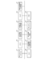
- FIG. 1 is a block diagram showing an input display apparatus according to Embodiment 1 of the present invention
- FIG. 2 is a hardware block diagram of the input display apparatus according to Embodiment 1 of the present invention.
- the operation reception unit 1 is realized by a pointing device 21 and performs a process of receiving a tracing operation as a user operation.
- the pointing device 21 is assumed to use a touch panel.
- the pointing device 21 is not limited to the touch panel.
- a joystick, a pointing stick (track point), a touch pad, a stylus, a data glove, A trackball, a pen tablet, a mouse, a light pen, a joypad, or the like can be used.
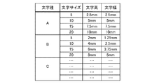
- the character management DB 2 is realized by, for example, a memory 22 such as a RAM or a hard disk, and stores a character attribute table indicating a correspondence relationship between a character type, a character size, a character height, and a character width.
- the character management unit 3 is realized by, for example, a character management processing circuit 23 configured by a semiconductor integrated circuit or a one-chip microcomputer on which a CPU (Central Processing Unit) is mounted.
- the character management unit 3 sets the size of characters to be displayed on the display 29 in advance, refers to the character attribute table stored in the character management DB 2, and tracks the character attribute information indicating the character height corresponding to the character size. A process of outputting to the image generation unit 4 is performed.
- the trajectory image generation unit 4 is realized by an image generation processing circuit 24 configured by, for example, a semiconductor integrated circuit or a one-chip microcomputer on which a GPU (Graphics Processing Unit) is mounted.
- the trajectory image generation unit 4 performs a process of discriminating a trajectory of a line drawn by tracing from the tracing operation received by the operation receiving unit 1 and generating a trajectory image indicating the trajectory. At this time, a trajectory image having a line width corresponding to the character height indicated by the character attribute information output from the character management unit 3 is generated.
- the character string acquisition unit 5 includes a voice detection unit 6, a voice recognition dictionary DB 7, and a voice recognition unit 8.
- the character string acquisition unit 5 performs a process of acquiring a character string indicating a voice recognition result.
- the voice detection unit 6 is realized by, for example, a microphone 25 and detects a user's voice.
- the speech recognition dictionary DB 7 is realized by a memory 26 such as a RAM or a hard disk, and the speech recognition dictionary DB 7 includes, for example, an acoustic model in which acoustic features of phonemes that are small units of human speech are described, and It is composed of a recognition dictionary in which words for speech recognition are described.
- the voice recognition unit 8 is realized by a voice recognition processing circuit 27 constituted by, for example, a semiconductor integrated circuit mounted with a CPU or a one-chip microcomputer, and recognizes the voice detected by the voice detection unit 6. It is equipped with a speech recognition engine. That is, the voice recognition unit 8 analyzes the voice detected by the voice detection unit 6, calculates the acoustic feature of the voice, and calculates the voice feature from the words described in the recognition dictionary of the voice recognition dictionary DB 7. A process of searching for a word having an acoustic feature closest to the acoustic feature and outputting a character string indicating the word to the display control unit 9 as a character string indicating a speech recognition result is performed.
- a voice recognition processing circuit 27 constituted by, for example, a semiconductor integrated circuit mounted with a CPU or a one-chip microcomputer, and recognizes the voice detected by the voice detection unit 6. It is equipped with a speech recognition engine. That is, the voice recognition unit 8 analyzes the voice detected by the voice detection unit 6, calculates the
- FIG. 1 shows an example in which the character string acquisition unit 5 includes the voice recognition dictionary DB 7 and the voice recognition unit 8
- the data transmission / reception unit is a network communication device such as a network card capable of transmitting / receiving data to / from a voice recognition server (not shown) via a communication path such as the Internet or a LAN.
- Data indicating the detected voice is transmitted to the voice recognition server.
- the voice recognition server is equipped with a voice recognition engine that recognizes voice.
- the voice recognition server recognizes the voice and generates a character string indicating the voice recognition result. It transmits to the data transmission / reception unit.
- the data transmission / reception unit receives a character string indicating the speech recognition result transmitted from the speech recognition server, the data transmission / reception unit outputs the character string to the display control unit 9.
- the display control unit 9 is realized by a display processing circuit 28 configured by, for example, a semiconductor integrated circuit in which a GPU is mounted or a one-chip microcomputer.
- the display control unit 9 performs a process of displaying the trajectory image generated by the trajectory image generation unit 4 on the display 29 and displaying the character string acquired by the character string acquisition unit 5 on the trajectory image. That is, when the trajectory image is generated by the trajectory image generation unit 4 before the character string is output from the voice recognition unit 8 of the character string acquisition unit 5, the display control unit 9 displays the trajectory image on the display 29. Thereafter, the character string output from the voice recognition unit 8 of the character string acquisition unit 5 is displayed over the trajectory image.
- the process waits until the trajectory image is generated by the trajectory image generation unit 4.
- the trajectory image is displayed on the display 29, and the character string is displayed on the trajectory image so as to be displayed.
- the display control unit 9 performs a process of erasing the display of the trajectory image after displaying the character string on the trajectory image.
- the character string temporary storage unit 10 is realized by, for example, a memory 30 such as a RAM or a hard disk, and temporarily stores the character string output from the voice recognition unit 8 of the character string acquisition unit 5.
- FIG. 1 is a hardware configuration diagram when the input display device is configured by a computer.
- the character management DB 2 When the input display device is configured by a computer, the character management DB 2, the speech recognition dictionary DB 7, and the character string temporary storage unit 10 are configured on the memory 41 of the computer, and the operation reception unit 1, character management unit 3, locus image generation
- the program describing the processing contents of the unit 4, the voice detection unit 6, the voice recognition unit 8, and the display control unit 9 is stored in the memory 41, and the processor 42 executes the program stored in the memory 41. That's fine.
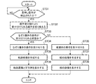
- 4 and 5 are flowcharts showing an input display method which is a processing content of the input display device according to the first embodiment of the present invention.
- FIG. 6 is an explanatory diagram showing a character attribute table stored in the character management DB 2.
- the character attribute table of FIG. 6 the character height and the character width corresponding to the character size are described for each character type (for example, Mincho, Gothic, etc.).
- the size of characters to be displayed on the display 29 is set in advance.
- the character management unit 3 refers to the character attribute table stored in the character management DB 2 and corresponds to the character size.
- Character attribute information indicating the character height to be output is output to the trajectory image generation unit 4 (step ST1 in FIG. 4).
- the character management unit 3 outputs character attribute information indicating the character height and the character width corresponding to the character size to the display control unit 9.
- margins are provided at the top and bottom of the character, but the character height indicated by the character attribute information and the line width of the trajectory image may match without providing a margin.
- the operation reception unit 1 receives the tracing operation and outputs the tracing operation content to the trajectory image generation unit 4 (step ST4).
- the tracing operation content corresponds to time-series data indicating a continuous change in the position (coordinates on the touch panel) of the finger or input pen in contact with the touch panel.
- the trace image generation unit 4 determines the trace of the line drawn by the trace from the operation content (step ST5).
- the operation content of the trace shows the continuous change of the contact position with respect to the touch panel, and therefore, the trajectory of the line drawn by the trace is determined by connecting the contact positions in time series. Can do.
- the trajectory image generation unit 4 determines the trajectory of the line drawn by tracing
- the trajectory image generation unit 4 generates a trajectory image indicating the trajectory and outputs the trajectory image to the display control unit 9 (step ST6).
- the line width of this trajectory image is the line width set in step ST2. In the above example, the line width of the trajectory image is set to “11 mm”, so that a trajectory image with a line width of “11 mm” is generated. To do.
- step ST7 When the voice detection unit 6 detects the user's voice (step ST7: YES), the voice recognition unit 8 of the character string acquisition unit 5 performs voice recognition processing using the voice recognition dictionary DB7. Then, a character string (text) indicating the recognition result of the voice is generated, and the character string is output to the display control unit 9 (step ST8). Since the voice recognition process by the voice recognition unit 8 is a known technique, a detailed description thereof will be omitted.
- the voice detected by the voice detection unit 6 is analyzed to calculate the acoustic characteristics of the voice, A word having an acoustic feature closest to the calculated acoustic feature is searched from words described in the recognition dictionary of the speech recognition dictionary DB7, and a character string indicating the word is used as a character string indicating a speech recognition result.
- a method of outputting can be considered.
- the user utters “Let's go to see cherry blossoms in the spring” and the voice recognition unit 8 says “Let's go to see the cherry blossoms in spring. "Is output.
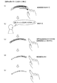
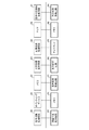
- FIG. 7 is an explanatory diagram illustrating a display process when a trajectory image is generated before a character string indicating a speech recognition result is generated.
- FIG. 8 is an explanatory diagram showing a display process when a character string indicating a speech recognition result is generated before a trajectory image is generated.
- the display control unit 9 As shown in FIG. 7A, the trajectory image is displayed on the display 29 (step ST12).
- the display of the trajectory image may be performed by displaying the entire trajectory image at the same time, or an animation that sequentially displays from the beginning of the character string to be displayed later.
- the display control unit 9 waits until a character string is output from the speech recognition unit 8 of the character string acquisition unit 5 (step ST13: NO), and the user speaks as shown in FIG. 7B.
- a character string indicating the speech recognition result is output from the speech recognition unit 8 (step ST13: YES)
- the character string is superimposed on the trajectory image as shown in FIG. Displayed (step ST14).
- the character size in the character string displayed on the trajectory image corresponds to the character height and the character width indicated by the character attribute information output from the character management unit 3.
- the display of the character string may be such that all the characters making up the character string are displayed at the same time, but in the form of an animation display that displays from the first character to the last character in order. There may be.
- the display control unit 9 utters before the user performs the tracing operation, so that a character string acquisition unit is output before the trajectory image is output from the trajectory image generation unit 4. 5 is output from the speech recognition unit 8 (in the case of step ST11 in FIG. 5: NO), the character string is stored in the character string temporary storage unit 10, and the trajectory image is generated from the trajectory image generation unit 4. Wait until it is output (step ST15: NO). After that, when the user performs a tracing operation and the trajectory image is output from the trajectory image generation unit 4 (in the case of YES at step ST15), the display control unit 9 performs a character string from the character string temporary storage unit 10. As shown in FIG.
- the trajectory image is displayed on the display 29, and the character string is superimposed on the trajectory image. That is, the display control unit 9 displays the trajectory image and the character string so as to overlap each other at the same position (step ST16). However, the trajectory image and the character string may be displayed at the same time, but may be in the form of an animation that is displayed sequentially from the beginning of the character string.
- the display control unit 9 erases the trajectory image and displays only the character string as shown in FIGS. Is displayed (step ST17).
- the trajectory image may be erased by deleting the entire trajectory image at the same time, or an animation may be performed in which the trajectory image is erased sequentially from the beginning of the character string.
- the operation accepting unit 1 that accepts the tracing operation and the locus of the line drawn by the tracing from the tracing operation accepted by the operation accepting unit 1
- a trajectory image generation unit 4 that generates a trajectory image indicating the trajectory and a character string acquisition unit 5 that acquires a character string indicating a speech recognition result
- the display control unit 9 generates a trajectory image.
- the trajectory image generated by the unit 4 is displayed on the display 29, and the character string acquired by the character string acquisition unit 5 is displayed so as to be superimposed on the trajectory image. There is an effect that a character string indicating the speech recognition result can be displayed.
- the display control unit 9 when the trajectory image is generated by the trajectory image generation unit 4 before the display control unit 9 outputs the character string from the voice recognition unit 8 of the character string acquisition unit 5.
- the character string output from the voice recognition unit 8 of the character string acquisition unit 5 is displayed on the trajectory image, while the trajectory image generation unit 4 generates the trajectory image.
- the process waits until a trajectory image is generated by the trajectory image generation unit 4, and a trajectory image is generated by the trajectory image generation unit 4. Then, the trajectory image is displayed on the display 29, and the character string is displayed so as to be superimposed on the trajectory image.
- the line width of the trajectory image is set to the line width corresponding to the character height of the character size set in advance, but depending on the state of the tracing operation by the user
- the line width of the trajectory image may be set.
- FIG. 9 is a block diagram showing an input display device according to Embodiment 2 of the present invention
- FIG. 10 is a hardware block diagram of the input display device according to Embodiment 2 of the present invention.
- the operation state detection unit 11 is realized by an operation state detection processing circuit 31 configured by, for example, a semiconductor integrated circuit or a one-chip microcomputer mounted with a CPU. Performs processing to detect the status. That is, the operation state detection unit 11 detects, for example, the pressure (writing pressure) of the user's finger or input pen on the touch panel that is the pointing device 21 as the operation state received by the operation reception unit 1.
- the trajectory image generation unit 12 is realized by an image generation processing circuit 32 configured by, for example, a semiconductor integrated circuit in which a GPU is mounted or a one-chip microcomputer. Similar to the trajectory image generation unit 4 in FIG. 1, the trajectory image generation unit 12 discriminates the trajectory of the line drawn by the tracing from the tracing operation received by the operation reception unit 1, and indicates the trajectory. A process for generating a trajectory image is performed. At that time, unlike the trajectory image generation unit 4 in FIG. 1, a trajectory image having a line width corresponding to the operation state detected by the operation state detection unit 11 is generated.
- the display control unit 13 is realized by, for example, a display processing circuit 33 configured by a semiconductor integrated circuit or a one-chip microcomputer mounted with a GPU, and performs display processing similar to the display control unit 9 in FIG. carry out. Further, the display control unit 13 changes the character size of the characters constituting the character string acquired by the character string acquisition unit 5 in accordance with the line width set by the trajectory image generation unit 12, and uses the changed character size. A process of displaying the character string on the trajectory image is performed.
- the input display device may be configured by a computer.
- the character management DB 2, the speech recognition dictionary DB 7, and the character string temporary storage unit 10 are configured on the memory 41 of the computer shown in FIG.
- a program describing processing contents of the operation state detection unit 11, the trajectory image generation unit 12, the voice detection unit 6, the voice recognition unit 8, and the display control unit 13 is stored in the memory 41
- the processor 42 is stored in the memory 41.
- 11 and 5 are flowcharts showing an input display method which is the processing content of the input display device according to the second embodiment of the present invention. 11, the same step numbers as those in FIG. 4 indicate the same or corresponding parts.
- the touch panel which is the pointing device 21 is equipped with a writing pressure detection sensor for detecting writing pressure.
- the operation state detection unit 11 acquires a writing pressure detection result from a writing pressure detection sensor mounted on the pointing device 21, so that the operation state received by the operation reception unit 1 is a touch panel that is the pointing device 21. Is detected (step ST21 in FIG. 11).
- the trajectory image generation unit 12 detects the user's writing pressure and the character attribute information output from the character management unit 3. Is set from the character height indicated by (step ST22). For example, if the character height indicated by the character attribute information is set to the reference line width of the trajectory image and the user's writing pressure is greater than or equal to a preset reference value, the greater the writing pressure is, the greater the reference value is An offset value is set, and a value obtained by adding the reference line width and the offset value is determined as the line width of the final trajectory image.
- Final trace image line width reference line width + offset value
- the larger the pen pressure is the larger the offset value is set. Then, a value obtained by subtracting the offset value from the reference line width is determined as the line width of the final trajectory image.
- Final trace image line width reference line width-offset value
- the display control unit 13 displays the trajectory image and the character string on the display 29 according to the flowchart of FIG. 5 in the same manner as the display control unit 9 of FIG.
- the trajectory image generation unit 12 makes the final line width of the trajectory image thicker than the reference line width. If so, the character size of the characters constituting the character string is increased according to the line width of the final trajectory image, and the character string is displayed on the trajectory image.
- the line width of the final trajectory image is set to “10 mm”
- the characters constituting the character string The character height is changed to “10 mm” and the character string is displayed on the trajectory image.
- the character height and the line width of the trajectory image match, but when providing margins at the top and bottom of the character, for example, if both the top and bottom margins are "1 mm”
- the character height of the characters constituting the character string is changed to “8 mm”, and the character string is displayed on the trajectory image.
- the display control unit 13 determines the character string according to the line width of the final trajectory image.
- the character height and the line width of the trajectory image match.
- margins are provided at the top and bottom of the character, for example, both the top and bottom margins are assumed to be “0.5 mm”.
- the character height of the characters constituting the character string is changed to “2 mm”, and the character string is displayed on the trajectory image.
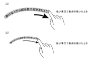
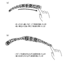
- FIG. 12 is an explanatory diagram showing a trajectory image in which the line width is set according to the user's writing pressure.
- FIG. 12A shows a trajectory image in which a thick line width is set because the user's writing pressure is equal to or higher than the reference value
- FIG. 12B shows that the user's writing pressure is less than the reference value. For this reason, a trajectory image in which a thin line width is set is shown.
- the operation state detection unit 11 detects the user's writing pressure on the touch panel that is the pointing device 21 as the operation state received by the operation reception unit 1, but this is an example.
- the user may detect a speed of tracing the touch panel that is the pointing device 21.
- the speed of tracing the touch panel if the operation state detection unit 11 specifies a continuous change in the contact position with respect to the touch panel from the contents of the tracing operation received by the operation reception unit 1, the unit time of the touch position with respect to the touch panel is determined. It can be determined from the change in hits.
- the trajectory image generation unit 12 indicates the tracing speed and the character attribute information output from the character management unit 3.
- the line width of the generated trajectory image is set from the character height. For example, if the character height indicated by the character attribute information is set as the reference line width of the trajectory image and the tracing speed is equal to or higher than the preset reference value, the larger the tracing speed is, the larger the offset value is.
- the value obtained by adding the reference line width and the offset value is determined as the final line width of the trajectory image.
- Final trace image line width reference line width + offset value
- a value obtained by subtracting the offset value from the line width is determined as the line width of the final trajectory image.
- Final trace image line width reference line width-offset value
- FIG. 13 is an explanatory diagram showing a trajectory image in which the line width is set according to the tracing speed.
- FIG. 13A shows a trajectory image in which a thick line width is set because the tracing speed is greater than or equal to the reference value
- FIG. 13B shows that the tracing speed is less than the reference value.
- a trajectory image in which a thin line width is set is shown.
- FIG. 14 is an explanatory diagram showing a trajectory image in which the line width is set according to the user's writing pressure and the tracing speed that change midway.
- FIG. 14A shows a trajectory image when the tracing speed is gradually increased or when the user's writing pressure is gradually increased, and the line width of the trajectory image gradually increases. Yes.
- FIG. 14B shows a trajectory image when the tracing speed or the user's writing pressure changes irregularly, and the line width of the trajectory image becomes thicker or thinner.
- the operation state detection unit 11 that detects the state of the operation received by the operation reception unit 1
- the trajectory image generation unit 12 includes the operation state detection unit 11. Since it is configured to generate a trajectory image having a line width corresponding to the state of the operation detected by the above, there is an effect that the display form of the character string can be diversified.
- the trajectory image generation unit 12 performs the operation state (for example, the user's writing pressure) received by the operation state detection unit 11 by the operation reception unit 1 and the character output from the character management unit 3.
- the line height of the generated trajectory image is set from the character height indicated by the attribute information.
- the operation receiving unit 1 does not use the character height indicated by the character attribute information output from the character management unit 3.
- the line width of the generated trajectory image may be set only from the state of the operation received by For example, a table storing a correspondence relationship between the user's writing pressure (or tracing speed) and the line width of the trajectory image is prepared, and the trajectory image generation unit 12 uses the table to determine the user's writing pressure (or A mode is conceivable in which the line width corresponding to the tracing speed is read and the line width is set as the line width of the trajectory image.
- the generation of a trajectory image having a line width corresponding to the state of the operation received by the operation receiving unit 1 is shown.
- You may make it change the lightness and darkness of the character displayed on the display 29.
- FIG. For example, there can be considered a mode in which the shade of the character is increased as the writing pressure of the user is higher or the tracing speed is higher.
- the thickness of characters displayed on the display 29 may be changed according to the state of the operation received by the operation receiving unit 1. For example, a mode in which the thickness of the character is increased as the writing pressure of the user is higher or the tracing speed is higher is conceivable.
- the character height of the character displayed superimposed on the trajectory image is shown.
- the line width of the trajectory image gradually increases, it is conceivable to change the character type in the order of character type A ⁇ character type B ⁇ character type C.
- Embodiment 3 FIG.
- the display control units 9 and 13 display the trajectory images generated by the trajectory image generation units 4 and 12 on the display 29.
- the determination result of the speech language is acquired.
- the trajectory image may be displayed in a color corresponding to the language indicated by the determination result.
- FIG. 15 is a block diagram showing an input display device according to Embodiment 3 of the present invention
- FIG. 16 is a hardware block diagram of the input display device according to Embodiment 3 of the present invention.
- the language discriminating unit 14 of the character string obtaining unit 5 is realized by a language discriminating processing circuit 34 constituted by, for example, a semiconductor integrated circuit mounted with a CPU or a one-chip microcomputer, and is detected by the voice detecting unit 6.
- the language determination process of the voice is performed, and the language determination result is output to the display control unit 15.
- the data transmission / reception unit is a network communication device such as a network card capable of transmitting / receiving data to / from a language discrimination server (not shown) via a communication path such as the Internet or a LAN.
- Data indicating the detected voice is transmitted to the language discrimination server.
- the language discrimination server is equipped with a language discrimination engine that discriminates the language of the voice.
- the language discrimination server recognizes the voice and obtains the language discrimination result of the voice. Transmit to the data transceiver.
- the data transmission / reception unit outputs the speech language discrimination result transmitted from the language discrimination server to the display control unit 15.
- the display control unit 15 is realized by a display processing circuit 35 configured by, for example, a semiconductor integrated circuit or a one-chip microcomputer mounted with a GPU, and performs display processing similar to that of the display control unit 13 of FIG. carry out. In addition, the display control unit 15 performs a process of displaying the trajectory image generated by the trajectory image generation unit 12 on the display 29 with a color corresponding to the language indicated by the determination result output from the language determination unit 14.
- the input display device may be configured by a computer.
- the character management DB 2, the speech recognition dictionary DB 7, and the character string temporary storage unit 10 are configured on the memory 41 of the computer shown in FIG.
- a program describing the processing contents of the operation state detection unit 11, the trajectory image generation unit 12, the voice detection unit 6, the voice recognition unit 8, the language determination unit 14, and the display control unit 15 is stored in the memory 41 and the processor 42.
- FIG. 17 and 5 are flowcharts showing an input display method which is the processing content of the input display device according to the third embodiment of the present invention.
- the same step numbers as in FIG. 11 indicate the same or corresponding parts.
- the voice detection unit 6 detects the user's voice
- the language discrimination unit 14 of the character string acquisition unit 5 performs language discrimination processing on the voice and outputs the language discrimination result to the display control unit 15 (FIG. 17).
- Step ST9 Since the speech language discrimination processing itself is a known technique, detailed description thereof is omitted.
- the display control unit 15 displays the trajectory image and the character string on the display 29 according to the flowchart of FIG. 5, similarly to the display control unit 13 of FIG. 9. However, unlike the display control unit 13 in FIG. 9, the display control unit 15 displays the trajectory image generated by the trajectory image generation unit 12 in a color corresponding to the language indicated by the determination result output from the language determination unit 14. 29. Until the voice detection unit 6 detects the user's voice, the language determination unit 14 cannot determine the language of the voice. Before the voice detection unit 6 detects the user's voice, the locus image generation is performed. When the trajectory image is generated by the unit 12, the display control unit 15 does not display the trajectory image until the voice detection unit 6 detects the user's voice.
- the locus is displayed in gray color, and when the user's voice is detected and a language discrimination result is obtained, the locus image is displayed in a color corresponding to the language. You may make it do.
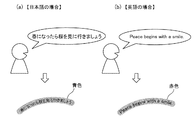
- FIG. 18 is an explanatory diagram showing the color of the trajectory image corresponding to the speech language.
- FIG. 18A shows a case where the language of the voice is Japanese, and the trajectory image is displayed in blue, for example.
- FIG. 18B shows the case where the language of the voice is English, and the trajectory image is displayed in red, for example.
- a blue locus image is displayed if the speech language is Japanese
- a red locus image is displayed if the speech language is English, but is merely an example, Needless to say, other colors may be displayed.
- the language discriminating unit 14 that performs the language discriminating process of the voice detected by the voice detecting unit 6 and outputs the discrimination result of the language is provided. Since the control unit 15 is configured to display the trajectory image generated by the trajectory image generation unit 12 on the display 29 in a color corresponding to the language indicated by the determination result output from the language determination unit 14, which language There is an effect that it is possible to intuitively grasp whether a character is displayed.
- Embodiment 4 FIG.
- the trajectory image and the character string are displayed, and then the trajectory image is deleted, so that only the character string is finally displayed on the display 29.
- An image of a picture generated in accordance with the picture writing operation may be displayed on the display 29.
- FIG. 19 is a block diagram showing an input display device according to Embodiment 4 of the present invention
- FIG. 20 is a hardware block diagram of the input display device according to Embodiment 4 of the present invention.
- the operation switching unit 16 is realized by an operation switching processing circuit 36 composed of, for example, a semiconductor integrated circuit mounted with a CPU or a one-chip microcomputer, and is used to switch operations accepted by the operation accepting unit 1. As an operation, for example, when a long press operation of the pointing device 21 is detected, a process of switching an operation accepted by the operation accepting unit 1 is performed.
- the operation switching unit 16 detects a long press operation of the pointing device 21 when the operation received by the operation receiving unit 1 is a tracing operation, and displays the operation received by the operation receiving unit 1 on the display 29. A process of switching to a drawing operation for drawing is performed. On the other hand, when the operation accepted by the operation accepting unit 1 is a drawing operation, when a long press operation of the pointing device 21 is detected, a process of switching the operation accepted by the operation accepting unit 1 to a tracing operation is performed.
- the picture image generation unit 17 is realized by, for example, an image generation processing circuit 37 configured by a semiconductor integrated circuit or a one-chip microcomputer mounted with a GPU.
- the operation switched by the operation switching unit 16 is If it is a drawing operation, a process of generating a picture image is performed in accordance with the drawing operation received by the operation receiving unit 1.
- the display control unit 18 is realized by, for example, a display processing circuit 38 constituted by a semiconductor integrated circuit or a one-chip microcomputer mounted with a GPU, and the operation switched by the operation switching unit 16 is traced. In the case of the above operation, display processing similar to that of the display control unit 15 in FIG. 15 is performed. If the operation switched by the operation switching unit 16 is a drawing operation, the display control unit 18 performs a process of displaying a picture image generated by the picture image generation unit 17 on the display 29.
- the input display device is configured by a computer. Also good.
- the character management DB 2, the speech recognition dictionary DB 7, and the character string temporary storage unit 10 are configured on the memory 41 of the computer shown in FIG.
- FIG. 21 is a flowchart showing the processing contents when the operation accepted by the operation accepting unit 1 is switched.
- FIG. 22 is an explanatory diagram illustrating an example of an operation for switching operations accepted by the operation accepting unit 1.
- FIG. 22 shows an example in which the operation for switching the operation accepted by the operation accepting unit 1 is a long press operation. For example, the same location on the touch panel that is the pointing device 21 is set in advance. This is an operation in which the user's finger is touching for more than a predetermined time.
- the operation accepting unit 1 when the operation accepted by the operation accepting unit 1 is a tracing operation at this time, when the operation switching unit 16 detects a long press operation of the pointing device 21, the operation accepting unit 1 subsequently performs an operation accepted by the operation accepting unit 1. A command to switch to drawing operation is output to the operation receiving unit 1.
- the operation accepted by the operation accepting unit 1 is a drawing operation, if a long press operation of the pointing device 21 is detected, the operation accepted by the operation accepting unit 1 is switched to the tracing operation thereafter. The command is output to the operation receiving unit 1.
- the operation receiving unit 1 switches an operation to be received in accordance with a command from the operation switching unit 16. Therefore, in a state where the operation to be accepted is switched to the tracing operation (in the case of YES at step ST33), the operation accepting unit 1 accepts the tracing operation and traces, as in the first to third embodiments.
- the contents of the writing operation are output to the trajectory image generation unit 12 (step ST34). Further, in a state where the operation to be accepted is switched to the drawing operation (in the case of NO at step ST33), the operation accepting unit 1 accepts the drawing operation and sends the contents of the drawing operation to the picture image generating unit 17. Output (step ST35).
- the trajectory image generating unit 12 creates a trajectory image according to the tracing operation content as in the second embodiment (step ST36).
- the picture image generating unit 17 When the operation receiving unit 1 receives a drawing operation, the picture image generating unit 17 generates a picture image according to the operation of the drawing (step ST37).
- FIG. 23 is an explanatory diagram showing an example of a picture image generated in accordance with the contents of the drawing operation. Since the process itself for generating the picture image according to the drawing operation content is a known technique, a detailed description thereof will be omitted.
- the contents of the drawing operation may include a function of changing the thickness and color of the line to be drawn, and an eraser function of erasing the line.
- the display control unit 18 displays the trajectory image and the character string output from the character string acquisition unit 5 on the display 29 as in the display control unit 15 of FIG. Processing is performed (step ST38). Further, when the picture image generation unit 17 generates a picture image, the display control unit 18 displays the picture image on the display 29 (step ST39).
- the operation switching unit 16 that switches the operation received by the operation receiving unit 1 and the operation switched by the operation switching unit 16 is a drawing operation.
- a picture image generation unit 17 that generates a picture image in accordance with the picture drawing operation received by the operation reception unit 1, and the operation switched by the operation switching unit 16 by the display control unit 18 If the operation is the same as the display control unit 15 in FIG. 15, the trajectory image and the character string are displayed in an overlapping manner.
- the operation switched by the operation switching unit 16 is a drawing operation, a picture image is generated. Since the picture image generated by the unit 17 is configured to be displayed, the picture image can be displayed on the display 29 together with the character string.
- the operation switching unit 16 detects a long press operation of the pointing device 21 when the operation accepted by the operation accepting unit 1 is a tracing operation
- the operation accepting operation is accepted by the operation accepting unit 1.
- the operation accepted by the operation accepting unit 1 is a drawing operation while detecting that a long press operation of the pointing device 21 is detected
- the operation accepted by the operation accepting unit 1 is changed to a tracing operation.
- An example of switching is shown.
- the operation switching method accepted by the operation accepting unit 1 is not limited to this, and the following switching method may be used.
- the operation accepted by the operation accepting unit 1 is set to a drawing operation.
- the operation switching unit 16 When a long press operation of the pointing device 21 is detected, the operation switching unit 16 is accepted by the operation accepting unit 1. A command to switch the operation to the tracing operation is output to the operation receiving unit 1 so that the operation receiving unit 1 can accept the tracing operation. When the tracing operation is finished, the operation accepted by the operation accepting unit 1 automatically returns to the drawing operation. After that, when the long pressing operation of the pointing device 21 is detected, the operation switching unit 16 again performs the operation. A command to switch the operation accepted by the accepting unit 1 to a tracing operation is output to the operation accepting unit 1 so that the operation accepting unit 1 can accept the tracing operation.
- the operation switching unit 16 switches the operation accepted by the operation accepting unit 1 when a long press operation of the pointing device 21 is detected, but the operation accepted by the operation accepting unit 1 is currently shown. However, information indicating whether the operation is a tracing operation or a drawing operation may be displayed on the display 29.
- the input display device and the input display method according to the present invention are suitable for those that need to be displayed in a user's free layout when displaying a character string indicating a speech recognition result on a display.
- 1 operation acceptance unit 2 character management DB, 3 character management unit, 4 trajectory image generation unit, 5 character string acquisition unit, 6 speech detection unit, 7 speech recognition dictionary DB, 8 speech recognition unit, 9 display control unit, 10 characters Temporary storage unit, 11 Operation state detection unit, 12 Trajectory image generation unit, 13 Display control unit, 14 Language discrimination unit, 15 Display control unit, 16 Operation switching unit, 17 Picture image generation unit, 18 Display control unit, 21 Pointing Device, 22 memory, 23 character management processing circuit, 24 image generation processing circuit, 25 microphone, 26 memory, 27 speech recognition processing circuit, 28 display processing circuit, 29 display, 30 memory, 31 operation state detection processing circuit, 32 image generation Processing circuit, 33 display processing circuit, 34 language discrimination processing circuit, 35 display processing circuit, 36 operation switching Sense circuit, 37 an image generating and processing circuitry, 38 display processing circuit, 41 a memory, 42 processor.
Landscapes
- Engineering & Computer Science (AREA)
- Theoretical Computer Science (AREA)
- Physics & Mathematics (AREA)
- General Physics & Mathematics (AREA)
- General Engineering & Computer Science (AREA)
- Human Computer Interaction (AREA)
- Computer Hardware Design (AREA)
- Audiology, Speech & Language Pathology (AREA)
- Health & Medical Sciences (AREA)
- Multimedia (AREA)
- Computational Linguistics (AREA)
- Acoustics & Sound (AREA)
- General Health & Medical Sciences (AREA)
- User Interface Of Digital Computer (AREA)
- Controls And Circuits For Display Device (AREA)
Abstract
Description
この入力表示装置では、ユーザがペン型入力器を用いて、線を描く操作を行うと、その線の始点と終点を検知し、その始点と終点を結ぶ直線をディスプレイに描画する。
その後、ユーザがマイクを用いて、音声を入力すると、その音声の認識処理を実施して、その音声の認識結果を示す文字列を描画済みの直線に沿うように表示する。
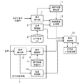
図1はこの発明の実施の形態1による入力表示装置を示す構成図であり、図2はこの発明の実施の形態1による入力表示装置のハードウェア構成図である。
図1及び図2において、操作受付部1はポインティングデバイス21で実現され、ユーザの操作として、なぞり書きの操作を受け付ける処理を実施する。
この実施の形態1では、ポインティングデバイス21として、タッチパネルを用いるものを想定しているが、タッチパネルに限るものではなく、例えば、ジョイスティック、ポインティング・スティック(トラックポイント)、タッチパッド、スタイラス、データグローブ、トラックボール、ペンタブレット、マウス、ライトペン、ジョイパッドなどを用いることができる。
文字管理部3は例えばCPU(Central Processing Unit)を実装している半導体集積回路やワンチップマイコンなどで構成されている文字管理処理回路23で実現されるものである。文字管理部3は事前にディスプレイ29に表示する文字のサイズが設定され、文字管理DB2に記憶されている文字属性表を参照して、その文字サイズに対応する文字高を示す文字属性情報を軌跡画像生成部4に出力する処理を実施する。
音声検出部6は例えばマイク25で実現され、ユーザの音声を検出する。
音声認識辞書DB7は例えばRAMやハードディスクなどのメモリ26で実現されるものであり、音声認識辞書DB7は、例えば、人間の発声の小さな単位である音素の音響特徴が記述されている音響モデルと、音声認識する言葉が記述されている認識辞書とから構成されている。
音声認識部8は例えばCPUを実装している半導体集積回路やワンチップマイコンなどで構成されている音声認識処理回路27で実現されるものであり、音声検出部6により検出された音声を認識する音声認識エンジンを搭載している。
即ち、音声認識部8は音声検出部6により検出された音声を分析して、その音声の音響特徴を算出し、音声認識辞書DB7の認識辞書に記述されている言葉の中から、その算出した音響特徴と最も近い音響特徴を有する言葉を探索し、その言葉を示す文字列を音声の認識結果を示す文字列として表示制御部9に出力する処理を実施する。
このデータ送受信部は、例えば、インターネットやLANなどの通信経路を介して、図示せぬ音声認識サーバとデータの送受信を行うことが可能なネットワークカードなどのネットワーク通信機器であり、音声検出部6により検出された音声を示すデータを音声認識サーバに送信する。
音声認識サーバは、音声を認識する音声認識エンジンを搭載しており、データ送受信部から送信された音声を示すデータを受信すると、その音声を認識して、その音声の認識結果を示す文字列を当該データ送受信部に送信する。
このデータ送受信部は、音声認識サーバから送信された音声の認識結果を示す文字列を受信すると、その文字列を表示制御部9に出力する。
即ち、表示制御部9は文字列取得部5の音声認識部8から文字列が出力される前に、軌跡画像生成部4により軌跡画像が生成された場合、その軌跡画像をディスプレイ29に表示した後、文字列取得部5の音声認識部8から出力された文字列を軌跡画像の上に重ねて表示する。一方、軌跡画像生成部4により軌跡画像が生成される前に、文字列取得部5の音声認識部8から文字列が出力された場合、軌跡画像生成部4により軌跡画像が生成されるまで待機し、軌跡画像生成部4により軌跡画像が生成されると、その軌跡画像をディスプレイ29に表示するとともに、その文字列を軌跡画像の上に重ねて表示する処理を実施する。
また、表示制御部9は文字列を軌跡画像の上に重ねて表示した後、その軌跡画像の表示を消す処理を実施する。
文字列一時保存部10は例えばRAMやハードディスクなどのメモリ30で実現され、文字列取得部5の音声認識部8から出力された文字列を一時的に保存する。
図3は入力表示装置がコンピュータで構成される場合のハードウェア構成図である。
入力表示装置がコンピュータで構成される場合、文字管理DB2、音声認識辞書DB7及び文字列一時保存部10をコンピュータのメモリ41上に構成するとともに、操作受付部1、文字管理部3、軌跡画像生成部4、音声検出部6、音声認識部8及び表示制御部9の処理内容を記述しているプログラムをメモリ41に格納し、プロセッサ42がメモリ41に格納されているプログラムを実行するようにすればよい。
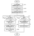
図4及び図5はこの発明の実施の形態1による入力表示装置の処理内容である入力表示方法を示すフローチャートである。
図6は文字管理DB2に記憶されている文字属性表を示す説明図である。
図6の文字属性表では、各々の文字種(例えば、明朝体、ゴシック体など)毎に、文字サイズに対応している文字高と文字幅が記述されている。
文字管理部3には、ディスプレイ29に表示する文字のサイズが事前に設定されており、文字管理部3は、文字管理DB2に記憶されている文字属性表を参照して、その文字サイズに対応する文字高を示す文字属性情報を軌跡画像生成部4に出力する(図4のステップST1)。
例えば、事前に設定されている文字の文字種が“A”で、その文字サイズが“10”であれば、文字高が“5mm”であることを示す文字属性情報が軌跡画像生成部4に出力される。
また、事前に設定されている文字の文字種が“B”で、その文字サイズが“5”であれば、文字高が“2mm”であることを示す文字属性情報が軌跡画像生成部4に出力される。
また、文字管理部3は、その文字サイズに対応する文字高及び文字幅を示す文字属性情報を表示制御部9に出力する。
例えば、文字属性情報が示す文字高が“10mm”であるとき、仮に文字の上部及び下部の余白が“0.5mm”に設定されているとすれば、軌跡画像の線幅を“11mm”に設定する。
11=10+0.5+0.5(mm)
ここでは、文字の上部及び下部に余白を設ける例を示しているが、余白を設けずに、文字属性情報が示す文字高と軌跡画像の線幅が一致するものであってもよい。
なぞり書きの操作内容は、タッチパネルに接触している指や入力ペンの位置(タッチパネル上の座標)の連続的な変化を示す時系列データに相当するものである。
なぞり書きの操作内容は、上述したように、タッチパネルに対する接触位置の連続的な変化を示しているので、時系列の接触位置を繋ぎ合わせることで、なぞり書きにより描かれる線の軌跡を判別することができる。
軌跡画像生成部4は、なぞり書きにより描かれる線の軌跡を判別すると、その軌跡を示す軌跡画像を生成し、その軌跡画像を表示制御部9に出力する(ステップST6)。
この軌跡画像の線幅は、ステップST2で設定した線幅であり、上記の例では、軌跡画像の線幅を“11mm”に設定しているので、線幅が“11mm”の軌跡画像を生成する。
音声認識部8による音声の認識処理自体は公知の技術であるため詳細な説明を省略するが、例えば、音声検出部6により検出された音声を分析して、その音声の音響特徴を算出し、音声認識辞書DB7の認識辞書に記述されている言葉の中から、その算出した音響特徴と最も近い音響特徴を有する言葉を探索し、その言葉を示す文字列を音声の認識結果を示す文字列として出力する方法が考えられる。
この実施の形態1では、説明の便宜上、ユーザが「春になったら桜を見に行きましょう」という発話をしており、音声認識部8が「春になったら桜を見に行きましょう」を示す文字列を出力するものとする。
また、図8は軌跡画像が生成される前に音声の認識結果を示す文字列が生成された場合の表示処理を示す説明図である。
表示制御部9は、文字列取得部5の音声認識部8から文字列が出力される前に、軌跡画像生成部4から軌跡画像が出力されると(図5のステップST11:YESの場合)、図7(a)に示すように、その軌跡画像をディスプレイ29に表示する(ステップST12)。
ここで、軌跡画像の表示は、軌跡画像の全体を同時に表示するようにしてもよいが、後で表示する文字列の先頭側から順次表示するアニメーションを行うようにしてもよい。
ここで、文字列の表示は、文字列を構成している全ての文字を同時に表示するようにしてもよいが、文字列の先頭の文字から順番に後尾の文字まで表示するアニメーション表示の形態であってもよい。
表示制御部9は、その後、ユーザがなぞり書きの操作を行うことで、軌跡画像生成部4から軌跡画像が出力されると(ステップST15:YESの場合)、文字列一時保存部10から文字列を読み出し、図8(b)に示すように、その軌跡画像をディスプレイ29に表示するとともに、その文字列を軌跡画像の上に重ねて表示する。即ち、表示制御部9は、軌跡画像と文字列を同じ位置に重ねて表示する(ステップST16)。ただし、軌跡画像及び文字列の表示は、全体を同時に表示するようにしてもよいが、文字列の先頭側から順次表示するアニメーション表示の形態であってもよい。
軌跡画像の消去は、軌跡画像の全体を同時に消去するようにしてもいが、文字列の先頭側から順次に消去するアニメーションを行うようにしてもよい。
ここでは、軌跡画像と文字列を重ねて表示してから、一定時間後に、軌跡画像を消去するものを想定しているが、文字列の表示が完了すると、直ちに、軌跡画像を消去するものであってもよい。
上記実施の形態1では、軌跡画像の線幅が事前に設定されている文字サイズの文字高に対応する線幅に設定されるものを示したが、ユーザによるなぞり書きの操作の状態に応じて軌跡画像の線幅が設定されるようにしてもよい。
図9及び図10において、図1及び図2と同一符号は同一または相当部分を示すので説明を省略する。
操作状態検知部11は例えばCPUを実装している半導体集積回路やワンチップマイコンなどで構成されている操作状態検知処理回路31で実現されるものであり、操作受付部1により受け付けられた操作の状態を検知する処理を実施する。
即ち、操作状態検知部11は、操作受付部1により受け付けられた操作の状態として、例えば、ポインティングデバイス21であるタッチパネルに対するユーザの指や入力ペンの圧力(筆圧)を感知する。
また、表示制御部13は軌跡画像生成部12により設定された線幅に応じて、文字列取得部5により取得された文字列を構成する文字の文字サイズを変更し、変更後の文字サイズで文字列を軌跡画像の上に重ねて表示する処理を実施する。
入力表示装置がコンピュータで構成される場合、文字管理DB2、音声認識辞書DB7及び文字列一時保存部10を図3に示すコンピュータのメモリ41上に構成するとともに、操作受付部1、文字管理部3、操作状態検知部11、軌跡画像生成部12、音声検出部6、音声認識部8及び表示制御部13の処理内容を記述しているプログラムをメモリ41に格納し、プロセッサ42がメモリ41に格納されているプログラムを実行するようにすればよい。
図11及び図5はこの発明の実施の形態2による入力表示装置の処理内容である入力表示方法を示すフローチャートである。
図11において、図4と同一のステップ番号は同一または相当部分を示すものである。
この実施の形態2では、ポインティングデバイス21であるタッチパネルに筆圧を感知する筆圧感知センサが搭載されているものとする。
操作状態検知部11は、ポインティングデバイス21に搭載されている筆圧感知センサから筆圧の感知結果を取得することで、操作受付部1により受け付けられた操作の状態として、ポインティングデバイス21であるタッチパネルに対するユーザの筆圧を検知する(図11のステップST21)。
例えば、文字属性情報が示す文字高を軌跡画像の基準の線幅に設定し、ユーザの筆圧が事前に設定されている基準値以上であれば、その筆圧が基準値より大きい程、大きなオフセット値を設定し、基準の線幅とオフセット値を加算した値を最終的な軌跡画像の線幅に決定する。
最終的な軌跡画像の線幅=基準の線幅+オフセット値
一方、ユーザの筆圧が事前に設定されている基準値より小さければ、その筆圧が基準値より小さい程、大きなオフセット値を設定し、基準の線幅からオフセット値を減算した値を最終的な軌跡画像の線幅に決定する。
最終的な軌跡画像の線幅=基準の線幅-オフセット値
ただし、この実施の形態2では、軌跡画像の線幅をユーザの筆圧に応じて設定しているので、軌跡画像生成部12が最終的な軌跡画像の線幅を基準の線幅より太くしている場合には、最終的な軌跡画像の線幅に応じて、文字列を構成する文字の文字サイズを大きくして、文字列を軌跡画像の上に表示する。
例えば、基準の線幅(=文字属性情報が示す文字高)が“5mm”であるとき、最終的な軌跡画像の線幅を“10mm”に設定していれば、文字列を構成する文字の文字高を“10mm”に変更して、文字列を軌跡画像の上に表示する。ここでは、文字高と軌跡画像の線幅が一致する例を示しているが、文字の上部及び下部に余白を設ける場合、例えば、上部及び下部の余白が共に“1mm”であるとすれば、文字列を構成する文字の文字高を“8mm”に変更して、文字列を軌跡画像の上に表示する。
例えば、基準の線幅(=文字属性情報が示す文字高)が“5mm”であるとき、最終的な軌跡画像の線幅を“3mm”に設定していれば、文字列を構成する文字の文字高を“3mm”に変更して、文字列を軌跡画像の上に表示する。ここでは、文字高と軌跡画像の線幅が一致する例を示しているが、文字の上部及び下部に余白を設ける場合、例えば、上部及び下部の余白が共に“0.5mm”であるとすれば、文字列を構成する文字の文字高を“2mm”に変更して、文字列を軌跡画像の上に表示する。
図12(a)は、ユーザの筆圧が基準値以上であるために、太い線幅が設定された軌跡画像を示しており、図12(b)は、ユーザの筆圧が基準値未満であるために、細い線幅が設定された軌跡画像を示している。
タッチパネルをなぞる速度については、操作状態検知部11が、操作受付部1により受け付けられたなぞり書きの操作内容から、タッチパネルに対する接触位置の連続的な変化を特定すれば、タッチパネルに対する接触位置の単位時間当りの変化から求めることができる。
例えば、文字属性情報が示す文字高を軌跡画像の基準の線幅に設定し、なぞる速度が事前に設定されている基準値以上であれば、なぞる速度が基準値より速い程、大きなオフセット値を設定し、基準の線幅とオフセット値を加算した値を最終的な軌跡画像の線幅に決定する。
最終的な軌跡画像の線幅=基準の線幅+オフセット値
一方、なぞる速度が事前に設定されている基準値より遅ければ、なぞる速度が基準値より遅い程、大きなオフセット値を設定し、基準の線幅からオフセット値を減算した値を最終的な軌跡画像の線幅に決定する。
最終的な軌跡画像の線幅=基準の線幅-オフセット値
図13(a)は、なぞる速度が基準値以上であるために、太い線幅が設定された軌跡画像を示しており、図13(b)は、なぞる速度が基準値未満であるために、細い線幅が設定された軌跡画像を示している。
図14は途中で変化するユーザの筆圧やなぞる速度に応じて線幅が設定された軌跡画像を示す説明図である。
図14(a)は、なぞる速度が徐々に速くなっている場合や、ユーザの筆圧が徐々に強くなっている場合の軌跡画像を示しており、軌跡画像の線幅が徐々に太くなっている。
図14(b)は、なぞる速度やユーザの筆圧が不規則に変化している場合の軌跡画像を示しており、軌跡画像の線幅が太くなったり、細くなったりしている。
例えば、ユーザの筆圧(または、なぞる速度)と、軌跡画像の線幅との対応関係を格納しているテーブルを用意し、軌跡画像生成部12が、そのテーブルからユーザの筆圧(または、なぞる速度)に対応する線幅を読み出し、その線幅を軌跡画像の線幅に設定する態様が考えられる。
また、軌跡画像生成部12により生成された軌跡画像の線幅に応じて、その軌跡画像に重ねて表示する文字の文字高を変えるものを示したが、軌跡画像の線幅に応じて、文字列を構成する文字の文字種を変えるようにしてもよい。
例えば、軌跡画像の線幅が徐々に太くなる場合、文字種を文字種A→文字種B→文字種Cのように変える態様が考えられる。
上記実施の形態1,2では、表示制御部9,13が、軌跡画像生成部4,12により生成された軌跡画像をディスプレイ29に表示するものを示したが、音声の言語の判別結果を取得し、その判別結果が示す言語に対応する色で、軌跡画像を表示するようにしてもよい。
図15及び図16において、図9及び図10と同一符号は同一または相当部分を示すので説明を省略する。
文字列取得部5の言語判別部14は例えばCPUを実装している半導体集積回路やワンチップマイコンなどで構成されている言語判別処理回路34で実現されるものであり、音声検出部6により検出された音声の言語判別処理を実施し、その言語の判別結果を表示制御部15に出力する。
このデータ送受信部は、例えば、インターネットやLANなどの通信経路を介して、図示せぬ言語判別サーバとデータの送受信を行うことが可能なネットワークカードなどのネットワーク通信機器であり、音声検出部6により検出された音声を示すデータを言語判別サーバに送信する。
言語判別サーバは、音声の言語を判別する言語判別エンジンを搭載しており、データ送受信部から送信された音声を示すデータを受信すると、その音声を認識して、その音声の言語判別結果を当該データ送受信部に送信する。
このデータ送受信部は、言語判別サーバから送信された音声の言語判別結果を表示制御部15に出力する。
また、表示制御部15は言語判別部14から出力された判別結果が示す言語に対応する色で、軌跡画像生成部12により生成された軌跡画像をディスプレイ29に表示する処理を実施する。
入力表示装置がコンピュータで構成される場合、文字管理DB2、音声認識辞書DB7及び文字列一時保存部10を図3に示すコンピュータのメモリ41上に構成するとともに、操作受付部1、文字管理部3、操作状態検知部11、軌跡画像生成部12、音声検出部6、音声認識部8、言語判別部14及び表示制御部15の処理内容を記述しているプログラムをメモリ41に格納し、プロセッサ42がメモリ41に格納されているプログラムを実行するようにすればよい。
図17及び図5はこの発明の実施の形態3による入力表示装置の処理内容である入力表示方法を示すフローチャートである。
図17において、図11と同一のステップ番号は同一または相当部分を示すものである。
文字列取得部5の言語判別部14は、音声検出部6がユーザの音声を検出すると、その音声の言語判別処理を実施し、その言語の判別結果を表示制御部15に出力する(図17のステップST9)。音声の言語判別処理自体は公知の技術であるため詳細な説明を省略する。
ただし、表示制御部15は、図9の表示制御部13と異なり、言語判別部14から出力された判別結果が示す言語に対応する色で、軌跡画像生成部12により生成された軌跡画像をディスプレイ29に表示する。
なお、音声検出部6がユーザの音声を検出するまでは、言語判別部14が音声の言語を判別することができないでの、音声検出部6がユーザの音声を検出する前に、軌跡画像生成部12により軌跡画像が生成された場合、音声検出部6がユーザの音声を検出するまでの間、表示制御部15は、軌跡画像の表示を行わない。また、音声検出部6がユーザの音声を検出するまでの間はグレーの色で軌跡を表示し、ユーザの音声を検出して言語の判別結果が出たら言語に対応する色で軌跡画像を表示するようにしてもよい。
図18(a)は音声の言語が日本語である場合を示しており、軌跡画像が例えば青色で表示される。
図18(b)は音声の言語が英語である場合を示しており、軌跡画像が例えば赤色で表示される。
ここでは、音声の言語が日本語であれば、青色の軌跡画像を表示し、音声の言語が英語であれば、赤色の軌跡画像を表示する例を示しているが、あくまでも一例に過ぎず、他の色で表示してもよいことは言うまでもない。
上記実施の形態1~3では、軌跡画像と文字列が表示された後、軌跡画像が消されることで、最終的には、文字列だけがディスプレイ29に表示されるものを示したが、ユーザの絵書きの操作にしたがって生成された絵の画像がディスプレイ29に表示されるようにしてもよい。
図19及び図20において、図15及び図16と同一符号は同一または相当部分を示すので説明を省略する。
操作切換部16は例えばCPUを実装している半導体集積回路やワンチップマイコンなどで構成されている操作切換処理回路36で実現されるものであり、操作受付部1により受け付けられる操作を切り換えるための操作として、例えば、ポインティングデバイス21の長押し操作を検出すると、操作受付部1により受け付けられる操作を切り換える処理を実施する。
即ち、操作切換部16は操作受付部1により受け付けられる操作がなぞり書きの操作であるとき、ポインティングデバイス21の長押し操作を検出すると、操作受付部1により受け付けられる操作を、ディスプレイ29に絵を描画する絵書きの操作に切り換える処理を実施する。一方、操作受付部1により受け付けられる操作が絵書きの操作であるとき、ポインティングデバイス21の長押し操作を検出すると、操作受付部1により受け付けられる操作をなぞり書きの操作に切り換える処理を実施する。
表示制御部18は例えばGPUを実装している半導体集積回路やワンチップマイコンなどで構成されている表示処理回路38で実現されるものであり、操作切換部16により切り換えられた操作が、なぞり書きの操作であれば、図15の表示制御部15と同様の表示処理を実施する。
表示制御部18は操作切換部16により切り換えられた操作が、絵書きの操作であれば、絵画像生成部17により生成された絵の画像をディスプレイ29に表示する処理を実施する。
入力表示装置がコンピュータで構成される場合、文字管理DB2、音声認識辞書DB7及び文字列一時保存部10を図3に示すコンピュータのメモリ41上に構成するとともに、操作受付部1、文字管理部3、操作状態検知部11、軌跡画像生成部12、操作切換部16、絵画像生成部17、音声検出部6、音声認識部8、言語判別部14及び表示制御部18の処理内容を記述しているプログラムをメモリ41に格納し、プロセッサ42がメモリ41に格納されているプログラムを実行するようにすればよい。
図21は操作受付部1により受け付けられる操作が切り換えられた際の処理内容を示すフローチャートである。
操作切換部16は、操作受付部1により受け付けられる操作を切り換えるための操作として、長押し操作を検出すると(図21のステップST31:YESの場合)、操作受付部1により受け付けられる操作を切り換える処理を実施する(ステップST32)。
図22は操作受付部1により受け付けられる操作を切り換えるための操作の一例を示す説明図である。
図22では、操作受付部1により受け付けられる操作を切り換えるための操作が、長押し操作である例を示しており、長押し操作は、例えば、ポインティングデバイス21であるタッチパネルの同じ場所を予め設定された時間以上継続して、ユーザの指が触れている操作である。
即ち、操作切換部16は、現時点において、操作受付部1により受け付けられる操作がなぞり書きの操作であるとき、ポインティングデバイス21の長押し操作を検出すると、以降、操作受付部1により受け付けられる操作を絵書きの操作に切り換える指令を操作受付部1に出力する。
一方、現時点において、操作受付部1により受け付けられる操作が絵書きの操作であるとき、ポインティングデバイス21の長押し操作を検出すると、以降、操作受付部1により受け付けられる操作をなぞり書きの操作に切り換える指令を操作受付部1に出力する。
したがって、操作受付部1は、受け付ける操作をなぞり書きの操作に切り換えている状態では(ステップST33:YESの場合)、上記実施の形態1~3と同様に、なぞり書きの操作を受け付けて、なぞり書きの操作内容を軌跡画像生成部12に出力する(ステップST34)。
また、操作受付部1は、受け付ける操作を絵書きの操作に切り換えている状態では(ステップST33:NOの場合)、絵書きの操作を受け付けて、絵書きの操作内容を絵画像生成部17に出力する(ステップST35)。
絵画像生成部17は、操作受付部1が絵書きの操作を受け付けると、その絵書きの操作内容にしたがって絵の画像を生成する(ステップST37)。
図23は絵書きの操作内容にしたがって生成される絵の画像の一例を示す説明図である。
絵書きの操作内容にしたがって絵の画像を生成する処理自体は公知の技術であるため詳細な説明を省略する。なお、絵書きの操作内容には、線を描画する機能のほかに、描画する線の太さや色を変える機能や、線を消去する消しゴムの機能などが含まれていてもよい。
また、表示制御部18は、絵画像生成部17が絵の画像を生成すると、その絵の画像をディスプレイ29に表示する(ステップST39)。
しかし、操作受付部1により受け付けられる操作の切り換え方法は、これに限るものではなく、下記の示すような切り換え方法を用いてもよい。
例えば、通常時において、操作受付部1により受け付けられる操作は、絵書きの操作に設定されており、ポインティングデバイス21の長押し操作を検出すると、操作切換部16が、操作受付部1により受け付けられる操作をなぞり書きの操作に切り換える指令を操作受付部1に出力して、操作受付部1によりなぞり書きの操作が受け付けられるようにする。
なぞり書きの操作が終わると、操作受付部1により受け付けられる操作が、自動的に絵書きの操作に戻り、その後、ポインティングデバイス21の長押し操作を検出すると、再び、操作切換部16が、操作受付部1により受け付けられる操作をなぞり書きの操作に切り換える指令を操作受付部1に出力して、操作受付部1によりなぞり書きの操作が受け付けられるようにする。
Claims (10)
- なぞり書きの操作を受け付ける操作受付部と、
前記操作受付部により受け付けられたなぞり書きの操作から、なぞり書きにより描かれる線の軌跡を判別して、前記軌跡を示す軌跡画像を生成する軌跡画像生成部と、
音声の認識結果を示す文字列を取得する文字列取得部と、
前記軌跡画像生成部により生成された軌跡画像をディスプレイに表示するとともに、前記文字列取得部により取得された文字列を前記軌跡画像の上に重ねて表示する表示制御部と
を備えた入力表示装置。 - 前記表示制御部は、前記文字列取得部により文字列が取得される前に、前記軌跡画像生成部により軌跡画像が生成された場合、前記軌跡画像をディスプレイに表示した後、前記文字列取得部により取得された文字列を前記軌跡画像の上に重ねて表示し、前記軌跡画像生成部により軌跡画像が生成される前に、前記文字列取得部により文字列が取得された場合、前記軌跡画像生成部により軌跡画像が生成されるまで待機し、前記軌跡画像生成部により軌跡画像が生成されると、前記軌跡画像と前記文字列を重ねて前記ディスプレイに表示することを特徴とする請求項1記載の入力表示装置。
- 前記表示制御部は、前記軌跡画像と前記文字列を重ねて表示した後、前記軌跡画像を消すことを特徴とする請求項1記載の入力表示装置。
- 前記表示制御部は、前記文字列取得部により取得された文字列の先頭の文字から順番に後尾の文字まで表示することを特徴とする請求項1記載の入力表示装置。
- 前記ディスプレイに表示する文字のサイズを管理する文字管理部を備え、
前記軌跡画像生成部は、前記文字管理部により管理されている文字のサイズに対応する線幅の軌跡画像を生成することを特徴とする請求項1記載の入力表示装置。 - 前記操作受付部により受け付けられた操作の状態を検知する操作状態検知部を備え、
前記軌跡画像生成部は、前記操作状態検知部により検知された操作の状態に対応する線幅の軌跡画像を生成することを特徴とする請求項1記載の入力表示装置。 - 前記軌跡画像生成部は、前記操作状態検知部により検知された操作の状態が途中で変化していれば、線幅が途中で変化する軌跡画像を生成することを特徴とする請求項6記載の入力表示装置。
- 前記文字列取得部は、音声の認識結果を示す文字列を取得する際、前記音声の言語の判別結果を取得し、
前記表示制御部は、前記文字列取得部により取得された判別結果が示す言語に対応する色で、前記軌跡画像生成部により生成された軌跡画像を表示することを特徴とする請求項1記載の入力表示装置。 - 前記操作受付部により受け付けられる操作を切り換える操作切換部と、
前記操作切換部により切り換えられた操作が、前記ディスプレイに絵を描画する絵書きの操作であれば、前記操作受付部により受け付けられた絵書きの操作にしたがって絵の画像を生成する絵画像生成部とを備え、
前記軌跡画像生成部は、前記操作切換部により切り換えられた操作が、前記なぞり書きの操作であるとき、前記操作受付部により受け付けられたなぞり書きの操作から、なぞり書きにより描かれる線の軌跡を判別して、前記軌跡を示す軌跡画像を生成し、
前記表示制御部は、前記操作切換部により切り換えられた操作が、前記絵書きの操作であれば、前記絵画像生成部により生成された絵の画像を前記ディスプレイに表示し、前記操作切換部により切り換えられた操作が、前記なぞり書きの操作であれば、前記軌跡画像生成部により生成された軌跡画像を前記ディスプレイに表示することを特徴とする請求項1記載の入力表示装置。 - 操作受付部が、なぞり書きの操作の受け付けを実施し、
軌跡画像生成部が、前記操作受付部により受け付けられたなぞり書きの操作から、なぞり書きにより描かれる線の軌跡を判別して、前記軌跡を示す軌跡画像を生成し、
文字列取得部が、音声の認識結果を示す文字列を取得し、
表示制御部が、前記軌跡画像生成部により生成された軌跡画像をディスプレイに表示するとともに、前記文字列取得部により取得された文字列を前記軌跡画像の上に重ねて表示する
入力表示方法。
Priority Applications (10)
| Application Number | Priority Date | Filing Date | Title |
|---|---|---|---|
| CN202110609797.5A CN113268186B (zh) | 2015-05-28 | 2015-05-28 | 输入显示装置和显示方法 |
| CN201580080158.7A CN107615232B (zh) | 2015-05-28 | 2015-05-28 | 输入显示装置和显示方法 |
| KR1020177027349A KR20170125366A (ko) | 2015-05-28 | 2015-05-28 | 입력 표시 장치, 입력 표시 방법, 및 프로그램 |
| US15/540,656 US10510322B2 (en) | 2015-05-28 | 2015-05-28 | Input display device, input display method, and computer-readable medium |
| KR1020197023932A KR102284238B1 (ko) | 2015-05-28 | 2015-05-28 | 입력 표시 장치, 입력 표시 방법, 및 프로그램 |
| PCT/JP2015/065431 WO2016189735A1 (ja) | 2015-05-28 | 2015-05-28 | 入力表示装置及び入力表示方法 |
| KR1020207027668A KR102295131B1 (ko) | 2015-05-28 | 2015-05-28 | 입력 표시 장치, 입력 표시 방법, 및 프로그램 |
| JP2017520187A JP6235763B2 (ja) | 2015-05-28 | 2015-05-28 | 入力表示装置、入力表示方法及び入力表示プログラム |
| EP15893369.7A EP3306452B1 (en) | 2015-05-28 | 2015-05-28 | Input display device and input display method |
| US16/669,132 US10748506B2 (en) | 2015-05-28 | 2019-10-30 | Input display device and input display method |
Applications Claiming Priority (1)
| Application Number | Priority Date | Filing Date | Title |
|---|---|---|---|
| PCT/JP2015/065431 WO2016189735A1 (ja) | 2015-05-28 | 2015-05-28 | 入力表示装置及び入力表示方法 |
Related Child Applications (2)
| Application Number | Title | Priority Date | Filing Date |
|---|---|---|---|
| US15/540,656 A-371-Of-International US10510322B2 (en) | 2015-05-28 | 2015-05-28 | Input display device, input display method, and computer-readable medium |
| US16/669,132 Division US10748506B2 (en) | 2015-05-28 | 2019-10-30 | Input display device and input display method |
Publications (1)
| Publication Number | Publication Date |
|---|---|
| WO2016189735A1 true WO2016189735A1 (ja) | 2016-12-01 |
Family
ID=57392633
Family Applications (1)
| Application Number | Title | Priority Date | Filing Date |
|---|---|---|---|
| PCT/JP2015/065431 Ceased WO2016189735A1 (ja) | 2015-05-28 | 2015-05-28 | 入力表示装置及び入力表示方法 |
Country Status (6)
| Country | Link |
|---|---|
| US (2) | US10510322B2 (ja) |
| EP (1) | EP3306452B1 (ja) |
| JP (1) | JP6235763B2 (ja) |
| KR (3) | KR20170125366A (ja) |
| CN (2) | CN107615232B (ja) |
| WO (1) | WO2016189735A1 (ja) |
Cited By (5)
| Publication number | Priority date | Publication date | Assignee | Title |
|---|---|---|---|---|
| JP2018195276A (ja) * | 2017-05-18 | 2018-12-06 | 深▲せん▼双猴科技有限公司 | 両面表示の同時通訳装置、方法、デバイス及び電子装置 |
| JP2019008388A (ja) * | 2017-06-21 | 2019-01-17 | ブラザー工業株式会社 | プログラム及び情報処理端末 |
| WO2019049312A1 (ja) * | 2017-09-08 | 2019-03-14 | 三菱電機株式会社 | 表示制御装置及び表示制御方法 |
| WO2019093156A1 (ja) * | 2017-11-10 | 2019-05-16 | ソニーセミコンダクタソリューションズ株式会社 | 表示処理装置および表示処理方法、並びにプログラム |
| US10884612B2 (en) | 2016-02-08 | 2021-01-05 | Mitsubishi Electric Corporation | Input display control device, input display control method, and input display system |
Families Citing this family (6)
| Publication number | Priority date | Publication date | Assignee | Title |
|---|---|---|---|---|
| KR20170125366A (ko) * | 2015-05-28 | 2017-11-14 | 미쓰비시덴키 가부시키가이샤 | 입력 표시 장치, 입력 표시 방법, 및 프로그램 |
| JP7023743B2 (ja) * | 2018-02-28 | 2022-02-22 | シャープ株式会社 | 情報処理装置、情報処理方法、及びプログラム |
| KR102603900B1 (ko) * | 2018-12-07 | 2023-11-17 | 미쓰비시덴키 가부시키가이샤 | 입력 표시 제어 장치, 입력 표시 제어 방법 및 입력 표시 시스템 |
| KR102165137B1 (ko) * | 2020-03-06 | 2020-10-13 | 바즈바이오메딕(주) | 무바늘 주사기 |
| KR102165136B1 (ko) * | 2020-03-06 | 2020-10-13 | 바즈바이오메딕(주) | 무바늘 주사기 |
| CN121010671A (zh) * | 2024-05-24 | 2025-11-25 | 北京字跳网络技术有限公司 | 一种图像编辑方法、装置、设备、介质及程序产品 |
Citations (8)
| Publication number | Priority date | Publication date | Assignee | Title |
|---|---|---|---|---|
| JPH0247763A (ja) * | 1988-08-09 | 1990-02-16 | Matsushita Electric Ind Co Ltd | 文書処理装置 |
| JPH0764998A (ja) * | 1993-08-25 | 1995-03-10 | Toshiba Corp | 文書作成装置及び文字軌跡入力方法 |
| JPH0830665A (ja) * | 1994-07-15 | 1996-02-02 | Sanyo Electric Co Ltd | 文字図形編集方法及び装置 |
| JPH10124033A (ja) * | 1996-08-30 | 1998-05-15 | Canon Inc | 文字処理装置、文字処理方法、及び、記憶媒体 |
| JP2004102632A (ja) * | 2002-09-09 | 2004-04-02 | Ricoh Co Ltd | 音声認識装置および画像処理装置 |
| JP2004206701A (ja) * | 2002-12-24 | 2004-07-22 | Fuji Xerox Co Ltd | 自由形状ペースト処理システム、方法及びプログラム |
| JP2012073857A (ja) * | 2010-09-29 | 2012-04-12 | Copcom Co Ltd | 画像処理プログラム、及び画像処理装置 |
| JP2012088969A (ja) * | 2010-10-20 | 2012-05-10 | Sharp Corp | 入力表示装置、入力表示方法、コンピュータプログラム及び記録媒体 |
Family Cites Families (32)
| Publication number | Priority date | Publication date | Assignee | Title |
|---|---|---|---|---|
| US5233438A (en) * | 1990-03-02 | 1993-08-03 | Brother Kogyo Kabushiki Kaisha | Entertainment apparatus for producing orchestral music accompaniment and a selected background video |
| JPH05127810A (ja) | 1991-11-05 | 1993-05-25 | Sharp Corp | 手書文字処理装置 |
| KR0126787B1 (ko) | 1994-06-22 | 1998-04-01 | 김광호 | 영상노래반주장치의 예약곡 표시방법 및 이에 적합한 장치 |
| JPH08305799A (ja) | 1995-05-11 | 1996-11-22 | Nec Home Electron Ltd | 筆圧検出手書きデータ入力方法及び装置 |
| JPH103516A (ja) | 1996-06-17 | 1998-01-06 | Canon Inc | 情報処理方法及び装置 |
| JP4158236B2 (ja) * | 1997-09-19 | 2008-10-01 | ソニー株式会社 | 遠隔操作装置 |
| JPH11154200A (ja) * | 1997-11-21 | 1999-06-08 | Oki Electric Ind Co Ltd | 文字認識装置 |
| US6202049B1 (en) * | 1999-03-09 | 2001-03-13 | Matsushita Electric Industrial Co., Ltd. | Identification of unit overlap regions for concatenative speech synthesis system |
| JP4632389B2 (ja) * | 2001-02-22 | 2011-02-16 | キヤノン株式会社 | 電子黒板装置およびその制御方法 |
| JP2002297305A (ja) * | 2001-03-30 | 2002-10-11 | Mitsubishi Electric Corp | 情報入力装置および携帯端末 |
| JP3865681B2 (ja) | 2002-10-18 | 2007-01-10 | 株式会社 ワコムアイティ | 毛筆描画装置、毛筆描画プログラムおよび毛筆描画方法 |
| CN1750117A (zh) * | 2004-09-16 | 2006-03-22 | 乐金电子(惠州)有限公司 | 伴唱机歌曲搜索系统及其旋律数据库构成方法 |
| JP4712675B2 (ja) | 2005-06-10 | 2011-06-29 | 株式会社メイクソフトウェア | 画像編集装置、画像編集方法、画像編集プログラム及び自動写真撮影装置 |
| US8885236B2 (en) * | 2006-06-30 | 2014-11-11 | Geoffrey J. Woolfe | Natural language color communication and system interface |
| CN101192107A (zh) * | 2006-11-28 | 2008-06-04 | 国际商业机器公司 | 用于输入并显示字符串的方法和设备 |
| CN101067929B (zh) * | 2007-06-05 | 2011-04-20 | 南京大学 | 使用共振峰增强提取话音共振峰轨迹的方法 |
| US8482545B2 (en) * | 2008-10-02 | 2013-07-09 | Wacom Co., Ltd. | Combination touch and transducer input system and method |
| US8780131B2 (en) * | 2008-12-19 | 2014-07-15 | Xerox Corporation | Systems and methods for text-based personalization of images |
| US9035973B2 (en) * | 2009-10-23 | 2015-05-19 | Kyocera Mita Corporation | Display device and display control method |
| CN201577180U (zh) * | 2009-11-10 | 2010-09-08 | 北京九鹤科技有限公司 | 声道管适配器 |
| KR101126167B1 (ko) | 2010-06-07 | 2012-03-22 | 삼성전자주식회사 | 터치 스크린 및 디스플레이 방법 |
| JP2012109901A (ja) * | 2010-11-19 | 2012-06-07 | Elmo Co Ltd | 資料提示装置 |
| KR101898202B1 (ko) * | 2012-02-09 | 2018-09-12 | 삼성전자주식회사 | 필기 인식을 위한 필기 입력 가이드 장치 및 방법 |
| US9529486B2 (en) * | 2012-03-29 | 2016-12-27 | FiftyThree, Inc. | Methods and apparatus for providing a digital illustration system |
| CN102768658A (zh) * | 2012-07-21 | 2012-11-07 | 韩晓刚 | 一种英汉智能翻译器 |
| JP5458161B1 (ja) * | 2012-10-23 | 2014-04-02 | 株式会社東芝 | 電子機器および方法 |
| KR102023008B1 (ko) | 2012-12-10 | 2019-09-19 | 엘지전자 주식회사 | 음성-텍스트 변환 디스플레이 장치 및 그 방법 |
| KR102051093B1 (ko) * | 2013-02-01 | 2019-12-02 | 엘지전자 주식회사 | 이동 단말기 및 그것의 제어 방법 |
| KR20140116642A (ko) * | 2013-03-25 | 2014-10-06 | 삼성전자주식회사 | 음성 인식 기반의 기능 제어 방법 및 장치 |
| US9710098B2 (en) * | 2014-03-31 | 2017-07-18 | Samsung Display Co., Ltd. | Method and apparatus to reduce latency of touch events |
| CN104391643A (zh) * | 2014-10-30 | 2015-03-04 | 深圳市金立通信设备有限公司 | 一种终端 |
| KR20170125366A (ko) * | 2015-05-28 | 2017-11-14 | 미쓰비시덴키 가부시키가이샤 | 입력 표시 장치, 입력 표시 방법, 및 프로그램 |
-
2015
- 2015-05-28 KR KR1020177027349A patent/KR20170125366A/ko not_active Ceased
- 2015-05-28 CN CN201580080158.7A patent/CN107615232B/zh active Active
- 2015-05-28 JP JP2017520187A patent/JP6235763B2/ja active Active
- 2015-05-28 WO PCT/JP2015/065431 patent/WO2016189735A1/ja not_active Ceased
- 2015-05-28 CN CN202110609797.5A patent/CN113268186B/zh active Active
- 2015-05-28 US US15/540,656 patent/US10510322B2/en active Active
- 2015-05-28 KR KR1020207027668A patent/KR102295131B1/ko active Active
- 2015-05-28 KR KR1020197023932A patent/KR102284238B1/ko active Active
- 2015-05-28 EP EP15893369.7A patent/EP3306452B1/en active Active
-
2019
- 2019-10-30 US US16/669,132 patent/US10748506B2/en active Active
Patent Citations (8)
| Publication number | Priority date | Publication date | Assignee | Title |
|---|---|---|---|---|
| JPH0247763A (ja) * | 1988-08-09 | 1990-02-16 | Matsushita Electric Ind Co Ltd | 文書処理装置 |
| JPH0764998A (ja) * | 1993-08-25 | 1995-03-10 | Toshiba Corp | 文書作成装置及び文字軌跡入力方法 |
| JPH0830665A (ja) * | 1994-07-15 | 1996-02-02 | Sanyo Electric Co Ltd | 文字図形編集方法及び装置 |
| JPH10124033A (ja) * | 1996-08-30 | 1998-05-15 | Canon Inc | 文字処理装置、文字処理方法、及び、記憶媒体 |
| JP2004102632A (ja) * | 2002-09-09 | 2004-04-02 | Ricoh Co Ltd | 音声認識装置および画像処理装置 |
| JP2004206701A (ja) * | 2002-12-24 | 2004-07-22 | Fuji Xerox Co Ltd | 自由形状ペースト処理システム、方法及びプログラム |
| JP2012073857A (ja) * | 2010-09-29 | 2012-04-12 | Copcom Co Ltd | 画像処理プログラム、及び画像処理装置 |
| JP2012088969A (ja) * | 2010-10-20 | 2012-05-10 | Sharp Corp | 入力表示装置、入力表示方法、コンピュータプログラム及び記録媒体 |
Non-Patent Citations (1)
| Title |
|---|
| See also references of EP3306452A4 * |
Cited By (8)
| Publication number | Priority date | Publication date | Assignee | Title |
|---|---|---|---|---|
| US10884612B2 (en) | 2016-02-08 | 2021-01-05 | Mitsubishi Electric Corporation | Input display control device, input display control method, and input display system |
| JP2018195276A (ja) * | 2017-05-18 | 2018-12-06 | 深▲せん▼双猴科技有限公司 | 両面表示の同時通訳装置、方法、デバイス及び電子装置 |
| JP2019008388A (ja) * | 2017-06-21 | 2019-01-17 | ブラザー工業株式会社 | プログラム及び情報処理端末 |
| WO2019049312A1 (ja) * | 2017-09-08 | 2019-03-14 | 三菱電機株式会社 | 表示制御装置及び表示制御方法 |
| JPWO2019049312A1 (ja) * | 2017-09-08 | 2020-01-16 | 三菱電機株式会社 | 表示制御装置及び表示制御方法 |
| WO2019093156A1 (ja) * | 2017-11-10 | 2019-05-16 | ソニーセミコンダクタソリューションズ株式会社 | 表示処理装置および表示処理方法、並びにプログラム |
| JPWO2019093156A1 (ja) * | 2017-11-10 | 2020-12-03 | ソニーセミコンダクタソリューションズ株式会社 | 表示処理装置および表示処理方法、並びにプログラム |
| JP7242546B2 (ja) | 2017-11-10 | 2023-03-20 | ソニーセミコンダクタソリューションズ株式会社 | 表示処理装置および表示処理方法、並びにプログラム |
Also Published As
| Publication number | Publication date |
|---|---|
| CN107615232B (zh) | 2021-12-14 |
| CN107615232A (zh) | 2018-01-19 |
| KR20200115670A (ko) | 2020-10-07 |
| US10748506B2 (en) | 2020-08-18 |
| JPWO2016189735A1 (ja) | 2017-07-13 |
| EP3306452A4 (en) | 2018-11-21 |
| CN113268186A (zh) | 2021-08-17 |
| JP6235763B2 (ja) | 2017-11-22 |
| EP3306452B1 (en) | 2022-04-20 |
| KR102295131B1 (ko) | 2021-08-27 |
| US20200066232A1 (en) | 2020-02-27 |
| CN113268186B (zh) | 2024-12-10 |
| KR20170125366A (ko) | 2017-11-14 |
| US10510322B2 (en) | 2019-12-17 |
| KR102284238B1 (ko) | 2021-07-30 |
| EP3306452A1 (en) | 2018-04-11 |
| US20180005604A1 (en) | 2018-01-04 |
| KR20190099347A (ko) | 2019-08-26 |
Similar Documents
| Publication | Publication Date | Title |
|---|---|---|
| JP6235763B2 (ja) | 入力表示装置、入力表示方法及び入力表示プログラム | |
| US10599393B2 (en) | Multimodal input system | |
| JP6355823B2 (ja) | 入力表示制御装置、入力表示制御方法及び入力表示システム | |
| KR102603900B1 (ko) | 입력 표시 제어 장치, 입력 표시 제어 방법 및 입력 표시 시스템 | |
| JP2007317159A (ja) | 電子装置の入力装置およびその入力方法 | |
| JP6463442B2 (ja) | 入力表示装置、入力表示方法及び入力表示プログラム | |
| JP6675472B2 (ja) | 入力表示装置 | |
| JP6656477B1 (ja) | 入力表示制御装置、入力表示制御方法及び入力表示システム | |
| US9430702B2 (en) | Character input apparatus and method based on handwriting | |
| JP6727279B2 (ja) | 表示制御装置、入力表示システム、表示制御方法及びプログラム | |
| JP6448838B2 (ja) | 表示制御装置、表示制御方法及びプログラム | |
| CN120447861A (zh) | 基于手势交互的语音输入方法、终端设备和存储介质 | |
| KR20160007313A (ko) | 필기 기반의 문자 입력 장치 및 방법 |
Legal Events
| Date | Code | Title | Description |
|---|---|---|---|
| 121 | Ep: the epo has been informed by wipo that ep was designated in this application |
Ref document number: 15893369 Country of ref document: EP Kind code of ref document: A1 |
|
| ENP | Entry into the national phase |
Ref document number: 2017520187 Country of ref document: JP Kind code of ref document: A |
|
| WWE | Wipo information: entry into national phase |
Ref document number: 15540656 Country of ref document: US |
|
| ENP | Entry into the national phase |
Ref document number: 20177027349 Country of ref document: KR Kind code of ref document: A |
|
| NENP | Non-entry into the national phase |
Ref country code: DE |
|
| WWE | Wipo information: entry into national phase |
Ref document number: 2015893369 Country of ref document: EP |