WO2016190297A1 - 光ファイバ - Google Patents
光ファイバ Download PDFInfo
- Publication number
- WO2016190297A1 WO2016190297A1 PCT/JP2016/065276 JP2016065276W WO2016190297A1 WO 2016190297 A1 WO2016190297 A1 WO 2016190297A1 JP 2016065276 W JP2016065276 W JP 2016065276W WO 2016190297 A1 WO2016190297 A1 WO 2016190297A1
- Authority
- WO
- WIPO (PCT)
- Prior art keywords
- optical fiber
- core
- refractive index
- less
- loss
- Prior art date
- Legal status (The legal status is an assumption and is not a legal conclusion. Google has not performed a legal analysis and makes no representation as to the accuracy of the status listed.)
- Ceased
Links
Images

Classifications
-
- G—PHYSICS
- G02—OPTICS
- G02B—OPTICAL ELEMENTS, SYSTEMS OR APPARATUS
- G02B6/00—Light guides; Structural details of arrangements comprising light guides and other optical elements, e.g. couplings
- G02B6/02—Optical fibres with cladding with or without a coating
- G02B6/02004—Optical fibres with cladding with or without a coating characterised by the core effective area or mode field radius
-
- G—PHYSICS
- G02—OPTICS
- G02B—OPTICAL ELEMENTS, SYSTEMS OR APPARATUS
- G02B6/00—Light guides; Structural details of arrangements comprising light guides and other optical elements, e.g. couplings
- G02B6/02—Optical fibres with cladding with or without a coating
- G02B6/028—Optical fibres with cladding with or without a coating with core or cladding having graded refractive index
- G02B6/0281—Graded index region forming part of the central core segment, e.g. alpha profile, triangular, trapezoidal core
-
- G—PHYSICS
- G02—OPTICS
- G02B—OPTICAL ELEMENTS, SYSTEMS OR APPARATUS
- G02B6/00—Light guides; Structural details of arrangements comprising light guides and other optical elements, e.g. couplings
- G02B6/02—Optical fibres with cladding with or without a coating
- G02B6/036—Optical fibres with cladding with or without a coating core or cladding comprising multiple layers
- G02B6/03616—Optical fibres characterised both by the number of different refractive index layers around the central core segment, i.e. around the innermost high index core layer, and their relative refractive index difference
- G02B6/03622—Optical fibres characterised both by the number of different refractive index layers around the central core segment, i.e. around the innermost high index core layer, and their relative refractive index difference having 2 layers only
- G02B6/03627—Optical fibres characterised both by the number of different refractive index layers around the central core segment, i.e. around the innermost high index core layer, and their relative refractive index difference having 2 layers only arranged - +
-
- G—PHYSICS
- G02—OPTICS
- G02B—OPTICAL ELEMENTS, SYSTEMS OR APPARATUS
- G02B6/00—Light guides; Structural details of arrangements comprising light guides and other optical elements, e.g. couplings
- G02B6/10—Light guides; Structural details of arrangements comprising light guides and other optical elements, e.g. couplings of the optical waveguide type
- G02B6/12—Light guides; Structural details of arrangements comprising light guides and other optical elements, e.g. couplings of the optical waveguide type of the integrated circuit kind
- G02B6/122—Basic optical elements, e.g. light-guiding paths
- G02B6/125—Bends, branchings or intersections
-
- G—PHYSICS
- G02—OPTICS
- G02B—OPTICAL ELEMENTS, SYSTEMS OR APPARATUS
- G02B6/00—Light guides; Structural details of arrangements comprising light guides and other optical elements, e.g. couplings
- G02B6/24—Coupling light guides
- G02B6/36—Mechanical coupling means
- G02B6/3616—Holders, macro size fixtures for mechanically holding or positioning fibres, e.g. on an optical bench
-
- G—PHYSICS
- G02—OPTICS
- G02B—OPTICAL ELEMENTS, SYSTEMS OR APPARATUS
- G02B6/00—Light guides; Structural details of arrangements comprising light guides and other optical elements, e.g. couplings
- G02B6/24—Coupling light guides
- G02B6/36—Mechanical coupling means
- G02B6/38—Mechanical coupling means having fibre to fibre mating means
- G02B6/3807—Dismountable connectors, i.e. comprising plugs
- G02B6/381—Dismountable connectors, i.e. comprising plugs of the ferrule type, e.g. fibre ends embedded in ferrules, connecting a pair of fibres
- G02B6/3818—Dismountable connectors, i.e. comprising plugs of the ferrule type, e.g. fibre ends embedded in ferrules, connecting a pair of fibres of a low-reflection-loss type
-
- G—PHYSICS
- G02—OPTICS
- G02B—OPTICAL ELEMENTS, SYSTEMS OR APPARATUS
- G02B6/00—Light guides; Structural details of arrangements comprising light guides and other optical elements, e.g. couplings
- G02B6/24—Coupling light guides
- G02B6/42—Coupling light guides with opto-electronic elements
- G02B6/4201—Packages, e.g. shape, construction, internal or external details
- G02B6/4287—Optical modules with tapping or launching means through the surface of the waveguide
- G02B6/4289—Optical modules with tapping or launching means through the surface of the waveguide by inducing bending, microbending or macrobending, to the light guide
-
- G—PHYSICS
- G02—OPTICS
- G02B—OPTICAL ELEMENTS, SYSTEMS OR APPARATUS
- G02B6/00—Light guides; Structural details of arrangements comprising light guides and other optical elements, e.g. couplings
- G02B6/10—Light guides; Structural details of arrangements comprising light guides and other optical elements, e.g. couplings of the optical waveguide type
- G02B6/12—Light guides; Structural details of arrangements comprising light guides and other optical elements, e.g. couplings of the optical waveguide type of the integrated circuit kind
- G02B2006/12083—Constructional arrangements
- G02B2006/12119—Bend
Definitions
- the present invention relates to an optical fiber.
- This application claims priority based on Japanese Patent Application No. 2015-107030 filed in Japan on May 27, 2015, the contents of which are incorporated herein by reference.
- a thin high-density cable as described in Patent Document 1 and Non-Patent Document 1 has been proposed.
- the small-diameter high-density cable is provided with a sheath directly on the cable core, so that local bending is unavoidably applied to the optical fiber.
- light confined inside the core of an optical fiber oozes out of the core by bending, that is, a loss occurs. Therefore, it is necessary to mount an optical fiber with good bending resistance on the thin high-density cable.
- optical fibers with reduced bending loss can be mounted on a thin high-density cable.
- This invention is made
- an optical fiber according to an aspect of the present invention is formed so that an optical fiber surrounds a core and an outer periphery of the core concentrically with the core, and is adjacent to the outer periphery of the core.
- a clad having at least an inner clad part and an outer clad part formed on an outer periphery of the inner clad part;
- the refractive index of the core is ⁇ 1, the maximum refractive index is ⁇ 1max, the outer radius is r1, the refractive index of the inner cladding is ⁇ 2, the minimum refractive index is ⁇ 2 min, the outer radius is r2, and the outer cladding is refracted.
- the cable cutoff wavelength is 1260 nm or less, and the MFD at a wavelength of 1310 nm is 8.6 ⁇ m or more and 9.2 ⁇ m or less.
- Loss increase at 1550 nm when wound 10 times on a mandrel with a radius of 15 mm is 0.02 dB or less, and loss increase at 1550 nm when wound once on a mandrel with a radius of 10 mm is 0.2 dB or less.
- the sandpaper tension winding loss increase at a wavelength of 1550 nm may be 0.3 dB / km or less.
- the increase in the sandpaper tension winding loss at a wavelength of 1550 nm of the optical fiber may be 0.15 dB / km or less.
- the increase in the sandpaper tension winding loss at the wavelength of 1550 nm of the optical fiber may be 0.10 dB / km or less. It may be 0.4 ⁇ r1 / r2 ⁇ 0.5. ⁇ 3 ⁇ 2min ⁇ 0.05% may be satisfied.
- the MFD at a wavelength of 1310 nm may be 8.8 ⁇ m or more and 9.2 ⁇ m or less.
- an optical fiber design area capable of achieving both a low bending loss characteristic that can be mounted on a thin high-density cable and an MFD equivalent to SSMF, which has been considered difficult until now, has been found. It was. With the optical fiber according to the present embodiment, it is possible to realize a small-diameter high-density optical cable capable of saving space without causing MFD mismatch.
- a plurality of categories of single-mode optical fibers (SMF) are defined in 652 (Characteristics-of-a-single-mode-optical-fibre-and-cable).
- SMF single-mode optical fibers
- C ITU-T G. 652.
- this optical fiber characteristic is defined as a characteristic of a general-purpose optical fiber (SSMF, Standard single-mode fiber).
- SSMF Standard single-mode fiber
- the optical fiber characteristics according to 652 are as follows.
- the mode field diameter (MFD) is 8.6 to 9.5 ⁇ m (tolerance ⁇ 0.6 ⁇ m) at a wavelength of 1310 nm.
- the clad diameter is 125.0 ⁇ m (tolerance is ⁇ 1 ⁇ m).
- the maximum amount of core eccentricity is 0.6 ⁇ m.
- the maximum cladding non-circularity is 1.0%.
- the maximum cable cut wavelength is 1260 nm.
- the macro bending loss is 0.1 dB at maximum at a radius of 30 mm, 100 turns, and a wavelength of 1625 nm. Proof stress is 0.69 GPa minimum.
- Wavelength dispersion coefficient is the minimum zero dispersion wavelength lambda 0min is 1300 nm, the maximum zero dispersion wavelength lambda 0max is 1324 nm, the maximum zero dispersion slope S 0max is 0.092ps / nm 2 ⁇ km.
- SSMF is used in the vicinity of a transmission system transmitter / receiver.
- G.P In order to reduce the splice loss due to MFD mismatch or the step in the OTDR waveform, G.P. It is desirable that it falls within the 652 standard, that is, the MFD at a wavelength of 1310 nm is in the range of 8.6 to 9.5 ⁇ m.
- the standard value of MFD (1.31 ⁇ m) is 9, 2 ⁇ 0.4 ⁇ m. Is almost. Therefore, it is more preferable that the optical fiber of the present embodiment has an MFD of 8.8 ⁇ m or more.
- the main optical characteristic defined in 652 is a cable cutoff wavelength ( ⁇ cc). Therefore, there is a demand for an optical fiber that has the above-mentioned MFD, satisfies the characteristics of a cable cut-off wavelength of 1260 nm or less, and obtains bending loss characteristics at a level that can be mounted on a thin high-density cable.
- optical fiber bending loss characteristics There are two types of optical fiber bending loss characteristics: loss due to macro bending (macro bending loss) and loss due to micro bending (micro bending loss).
- a thin high-density cable is required to have low (good) bend loss characteristics.
- the microbending loss is evaluated by, for example, an increase in sandpaper tension winding loss described in Reference Document 1 (Japanese Patent No. 3725523).
- the increase in sandpaper tension winding loss is measured by the following method.
- Sandpaper SiC (for example, model # 360) having an average particle diameter of 50 ⁇ m
- a body portion of a bobbin having a body diameter of 380 mm
- transmission loss is measured in a state where an optical fiber strand is wound around 100 gf around the sandpaper.
- the optical fiber is an optical fiber in which a UV curable resin or the like is coated on the outer periphery of the bare optical fiber.
- An optical fiber bare wire is an optical fiber that is drawn from an optical fiber preform and is not coated with a resin or the like. In this embodiment, when it is simply described as an optical fiber, it may be either a bare optical fiber or an optical fiber.
- Whether or not an optical fiber can be mounted on a thin high-density cable is finally determined by evaluating the temperature characteristics (cable characteristics) of transmission loss after mounting on the cable. Specifically, for example, when a temperature change defined in IEC 60794-3-11 is applied ( ⁇ 40 ° C. to ⁇ 45 ° C. on the low temperature side, + 60 ° C. to + 70 ° C., 2 cycles on the high temperature side), transmission loss Whether the fluctuation amount satisfies 0.15 dB / km or less is one of the indexes. On the other hand, the cable characteristics are greatly affected by the macro bending loss and the micro bending loss of the optical fiber. Therefore, by evaluating these two bending loss characteristics at the stage of the optical fiber strand, it is possible to determine whether or not it can be mounted on a small-diameter high-density cable.
- FIG. 1 shows a schematic diagram of a refractive index profile of an optical fiber according to this embodiment.
- the refractive index distribution shape is a shape in which a depressed structure is added to the core portion.
- the optical fiber has a core 11 and a clad 14. In the cross section perpendicular to the longitudinal direction of the optical fiber, the core 11 is provided at the center. Similarly, the clad 14 is concentric with the core 11 and surrounds the outer periphery of the core 11.
- the clad 14 has at least an inner clad portion 12 adjacent to the outer circumference of the core 11 and an outer clad portion 13 provided on the outer circumference.
- the refractive index of the core 11 is ⁇ 1, and the outer radius is r1.
- the refractive index of the inner cladding portion 12 is ⁇ 2, and the outer peripheral radius is r2.
- the outer cladding portion 13 has a refractive index of ⁇ 3 and an outer peripheral radius of r3.
- the refractive indexes ⁇ 1, ⁇ 2, and ⁇ 3 of each part are shown as constant values, but the refractive index of each part may have a distribution in which the refractive index varies depending on the position in the radial direction.
- ⁇ 1, ⁇ 2, and ⁇ 3 may be defined as relative refractive index differences.
- the outer peripheral radii r1, r2, and r3 are distances from the center 15 of the optical fiber to the outer periphery of each part. If the cross section perpendicular to the longitudinal direction of the optical fiber is circular, the center 15 of the optical fiber may be the center of the circle.
- the outer peripheral radius satisfies the relationship r1 ⁇ r2 ⁇ r3.
- the outer peripheral radius r3 of the outer cladding portion 13 may be 1 ⁇ 2 of the cladding diameter.
- ⁇ 1max> ⁇ 3max ⁇ ⁇ 3min> ⁇ 2min may be set with ⁇ 3max being the maximum value and ⁇ 3min being the minimum value.
- the range defining ⁇ 3max and ⁇ 3min is not limited to the entire area of the outer cladding portion 13, but may be a region that affects the optical characteristics, for example, a region having an outer peripheral radius that is twice as large as r2 to r2. Outside this region, ⁇ 3 may be outside the specified range.
- the optical fiber according to the present embodiment preferably has a relationship of ⁇ 3 ⁇ 2min ⁇ 0.08% and 0.35 ⁇ r1 / r2 ⁇ 0.55 in order to solve the above problems. Further, ⁇ 3 ⁇ 2min ⁇ 0.05% is particularly preferable. It is particularly preferable that 0.4 ⁇ r1 / r2 ⁇ 0.5. Considering the case where the refractive index ⁇ 3 of the outer cladding portion 13 is not a constant value, a value such as ⁇ 3max ⁇ 2min or ⁇ 3min ⁇ 2min can be used instead of ⁇ 3- ⁇ 2min.
- ⁇ cc of the optical fiber is preferably 1260 nm or less.
- the MFD at a wavelength of 1310 nm is preferably 8.6 ⁇ m or more and 9.2 ⁇ m or less, and particularly preferably 8.8 ⁇ m or more and 9.2 ⁇ m or less.
- the loss increase at 1550 nm when wound 10 times on a mandrel with a radius of 15 mm is 0.02 dB or less, and the loss increase at 1550 nm when wound once on a mandrel with a radius of 10 mm is 0.2 dB or less.
- the optical fiber used for measuring the macro bending loss is not particularly limited, but may be an optical fiber strand.
- the increase in the sandpaper tension winding loss at the wavelength of 1550 nm of the optical fiber is preferably 0.3 dB / km or less. Moreover, it is more preferable that the increase in the sandpaper tension winding loss at the wavelength of 1550 nm of the optical fiber is 0.15 dB / km or less. Furthermore, it is particularly preferable that the increase in the sandpaper tension winding loss at a wavelength of 1550 nm of the optical fiber is 0.10 dB / km or less.
- the optical fiber strand used for the measurement of the microbending loss is not particularly limited, an optical fiber strand in which a normal UV curable resin is coated on the outer periphery of the clad can be mentioned.
- the core 11 and the clad 14 are usually made of a quartz glass material.
- the quartz-based glass is silica (SiO 2 ) and may contain a dopant.
- Any of the core 11, the inner cladding portion 12, and the outer cladding portion 13 may be pure silica containing no dopant, or each may be silica containing a dopant.
- Examples of the dopant include one or more of Ge, B, Al, P, F, Cl, Na, K, and the like. The kind, combination, concentration, and the like of the dopant can be varied from part to part.
- one or more coating layers of plastic are provided on the outer periphery of the clad 14.
- a UV curable resin having a Young's modulus of 1.0 MPa or less is preferable.
- the secondary coating layer provided on the outer periphery of the primary coating layer is preferably a UV curable resin having a Young's modulus of 500 MPa or more.
- the UV curable resin that can be used for each coating layer include urethane acrylate, polybutadiene acrylate, epoxy acrylate, silicone acrylate, and polyester acrylate.
- Examples of the cladding diameter (outer diameter) of the optical fiber include 100 to 125 ⁇ m.
- Examples of the outer diameter of the primary coating layer include 130 to 250 ⁇ m.
- Examples of the outer diameter of the secondary coating layer include 160 to 400 ⁇ m.
- the shapes of the core 11, the inner cladding portion 12, and the outer cladding portion 13 may be substantially concentric in the cross section.
- the clad of the optical fiber may have only two parts, an inner clad part (first clad part) and an outer clad part (second clad part) from the core toward the outer periphery. You may have another part (3rd clad part etc.) on the outer periphery.
- a clad composed of first to third clad parts, a clad composed of first to fourth clad parts, and the like can be employed.
- the small-diameter high-density cable there is a structure in which the outer periphery of a cable core in which a plurality of optical fibers are assembled is covered with a protective tape, a cable sheath (outer jacket), or the like.
- the cable core may not include a member that supports the optical fiber such as a slot rod inside the optical fiber.
- the number of optical fiber cores assembled in the cable core is, for example, 24 to 200 cores.
- Strength members such as metal wires and reinforcing fibers can be embedded in the cable sheath.
- Table 1 shows the parameter values of the refractive index distribution of the optical fiber of the example.
- the maximum refractive index ⁇ 1max of the core is equal to ⁇ 1
- the minimum refractive index ⁇ 2min of the inner cladding portion is equal to ⁇ 2.
- Table 2 shows the optical characteristics of the optical fibers of the examples.
- the optical fiber of Table 1 has the same characteristics as SSMF, that is, the value of MFD (wavelength 1.31 ⁇ m) is 8.8 ⁇ m or more and the value of ⁇ cc (cable cutoff wavelength) is 1260 nm or less. is there. Furthermore, it satisfies the low bending loss (0.02 dB / 10 turn or less at a wavelength of 1.55 ⁇ m and a radius of 15 mm, 0.2 dB / turn or less at a wavelength of 1.55 ⁇ m and a radius of 10 mm) required for a thin high-density cable.
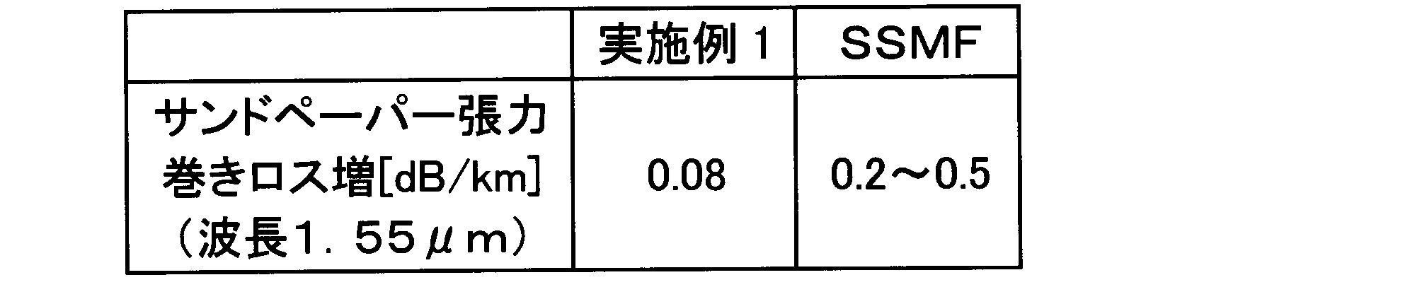
- Table 3 shows the results of the increase in the sandpaper tension winding loss of the optical fiber of the example. Table 3 also shows SSMF evaluation results as reference values. As can be seen from Table 3, in the optical fiber of the example, it can be seen that a value lower than SSMF is obtained.
- the optical fiber of the example is an optical fiber having a bending characteristic that can be mounted on a small-diameter high-density cable and having an MFD equivalent to SSMF.
- ⁇ 1 Core refractive index
- ⁇ 2 Inner cladding refractive index
- ⁇ 3 Outer cladding refractive index
- r1 Core outer radius
- r2 Inner cladding outer radius
- r3 Outer cladding outer radius
Landscapes
- Physics & Mathematics (AREA)
- General Physics & Mathematics (AREA)
- Optics & Photonics (AREA)
- Engineering & Computer Science (AREA)
- Microelectronics & Electronic Packaging (AREA)
- Optical Fibers, Optical Fiber Cores, And Optical Fiber Bundles (AREA)
- Light Guides In General And Applications Therefor (AREA)
Abstract
Description
本願は、2015年5月27日に、日本に出願された特願2015-107030号に基づき優先権を主張し、その内容をここに援用する。
光ファイバ素線の、波長1550nmにおけるサンドペーパー張力巻きロス増が0.10dB/km以下であってもよい。
0.4≦r1/r2≦0.5であってもよい。
Δ3-Δ2min≦0.05%であってもよい。
波長1310nmにおけるMFDが8.8μm以上、かつ9.2μm以下であってもよい。
本実施形態では、今まで困難と考えられてきた、細径高密度ケーブルに実装可能なレベルの低曲げ損失特性及びSSMFと同等レベルのMFDを両立させることが可能な光ファイバの設計領域を見出した。本実施形態に係る光ファイバにより、MFDのミスマッチを引き起こすことなく、省スペース化が可能な細径高密度光ケーブルを実現できる。
モードフィールド径(MFD)は、波長1310nmにおいて8.6~9.5μm(許容差±0.6μm)。
クラッド直径は、125.0μm(許容差は±1μm)。
コア偏心量は、最大で0.6μm。
クラッド非円率は、最大で1.0%。
ケーブルカット波長は最大で1260nm。
マクロベンディングロスは、半径30mm、100ターン、波長1625nmにおいて最大で0.1dB。
プルーフストレスは、最小で0.69GPa。
波長分散係数は、最小ゼロ分散波長λ0minが1300nm、最大ゼロ分散波長λ0maxが1324nm、最大ゼロ分散スロープS0maxが0.092ps/nm2×km。
胴径380mmのボビンの胴部分に、サンドペーパー(平均粒径50μmのSiC(例えば型番#360)を巻き付け、その周囲に100gfで、光ファイバ素線を1層巻きした状態で伝送損失を測定する。その後、この光ファイバ素線をボビンから繰り出し、張力をほとんどかけない状態で(このような状態は無張力の束と呼ばれている)伝送損失を測定する。そして、これらの伝送損失の差を求め、サンドペーパー張力巻きロス増(Δα)とする。
ここで、光ファイバ素線とは、光ファイバ裸線の外周にUV硬化樹脂などがコーティングされた光ファイバである。また、光ファイバ裸線とは、光ファイバ母材から線引きされた状態で、樹脂等によるコーティングがされていない光ファイバである。本実施形態において、単に光ファイバと記載する場合は光ファイバ裸線と光ファイバ素線とのどちらであってもよい。
一方、ケーブル特性は、光ファイバのマクロベンディングロス及びマイクロベンディングロスが大きく影響する。そのため、光ファイバ素線の段階でこれら二つの曲げ損失特性を評価することにより、細径高密度ケーブルに実装可能かどうかを判断することも可能である。
マクロベンディングロスの測定に使用する光ファイバは、特に限定されないが、光ファイバ素線であってもよい。
光ファイバのクラッドは、コアから外周に向かって、内クラッド部(第1クラッド部)と外クラッド部(第2クラッド部)との2つの部分のみを有してもよく、第2クラッド部の外周に、さらに他の部分(第3クラッド部等)を有してもよい。例えば、第1~第3クラッド部から構成されるクラッド、第1~第4クラッド部から構成されるクラッド等を採用することも可能である。
表1に、実施例の光ファイバの屈折率分布のパラメータ値を示す。コアの最大の屈折率Δ1maxはΔ1に等しく、内クラッド部の最小の屈折率Δ2minはΔ2に等しい。比屈折率差は、Δ3=0%を基準とした。


表3に、実施例の光ファイバのサンドペーパー張力巻きロス増の結果を示す。また、表3中には、参考値としてSSMFの評価結果も示す。表3を見てわかるように、実施例の光ファイバでは、SSMFより低い値が得られていることがわかる。
Claims (7)
- コアと、
前記コアと同芯状に前記コアの外周を取り囲むように形成され、前記コアの外周に隣接した内クラッド部と、前記内クラッド部の外周に形成される外クラッド部とを少なくとも有するクラッドと
を有する光ファイバにおいて、
前記コアの屈折率をΔ1、最大の屈折率をΔ1max、外周半径をr1とし、
前記内クラッド部の屈折率をΔ2、最小の屈折率をΔ2min、外周半径をr2とし、
前記外クラッド部の屈折率をΔ3、外周半径をr3とした場合、
Δ1max>Δ3>Δ2minであり、
Δ3-Δ2min≦0.08%であり、
r1<r2<r3であり、
0.35≦r1/r2≦0.55であり、
ケーブルカットオフ波長が1260nm以下であり、
波長1310nmにおけるMFDが8.6μm以上、かつ9.2μm以下である光ファイバ。 - 半径15mmのマンドレルに10回巻いたときの1550nmにおける損失増加が0.02dB以下であり、半径10mmのマンドレルに1回巻いたときの1550nmにおける損失増加が0.2dB以下であり、光ファイバ素線の、波長1550nmにおけるサンドペーパー張力巻きロス増が0.3dB/km以下である請求項1に記載の光ファイバ。
- 光ファイバ素線の、波長1550nmにおけるサンドペーパー張力巻きロス増が0.15dB/km以下である請求項1又は2に記載の光ファイバ。
- 光ファイバ素線の、波長1550nmにおけるサンドペーパー張力巻きロス増が0.10dB/km以下である請求項1又は2に記載の光ファイバ。
- 0.4≦r1/r2≦0.5である請求項1~4のいずれか1項に記載の光ファイバ。
- Δ3-Δ2min≦0.05%である請求項1~5のいずれか1項に記載の光ファイバ。
- 波長1310nmにおけるMFDが8.8μm以上、かつ9.2μm以下である請求項1~6のいずれか1項に記載の光ファイバ。
Priority Applications (4)
| Application Number | Priority Date | Filing Date | Title |
|---|---|---|---|
| CN201680002238.5A CN106796323B (zh) | 2015-05-27 | 2016-05-24 | 光纤 |
| JP2016564278A JPWO2016190297A1 (ja) | 2015-05-27 | 2016-05-24 | 光ファイバ |
| EP16800002.4A EP3173831A4 (en) | 2015-05-27 | 2016-05-24 | Optical fiber |
| US15/506,943 US9964697B2 (en) | 2015-05-27 | 2016-05-24 | Optical fiber |
Applications Claiming Priority (2)
| Application Number | Priority Date | Filing Date | Title |
|---|---|---|---|
| JP2015107030 | 2015-05-27 | ||
| JP2015-107030 | 2015-05-27 |
Publications (1)
| Publication Number | Publication Date |
|---|---|
| WO2016190297A1 true WO2016190297A1 (ja) | 2016-12-01 |
Family
ID=57392843
Family Applications (1)
| Application Number | Title | Priority Date | Filing Date |
|---|---|---|---|
| PCT/JP2016/065276 Ceased WO2016190297A1 (ja) | 2015-05-27 | 2016-05-24 | 光ファイバ |
Country Status (5)
| Country | Link |
|---|---|
| US (1) | US9964697B2 (ja) |
| EP (1) | EP3173831A4 (ja) |
| JP (2) | JPWO2016190297A1 (ja) |
| CN (1) | CN106796323B (ja) |
| WO (1) | WO2016190297A1 (ja) |
Cited By (6)
| Publication number | Priority date | Publication date | Assignee | Title |
|---|---|---|---|---|
| JP2019056837A (ja) * | 2017-09-21 | 2019-04-11 | 住友電気工業株式会社 | 光ファイバケーブル |
| WO2019172079A1 (ja) | 2018-03-08 | 2019-09-12 | 古河電気工業株式会社 | 光ファイバ |
| WO2020090742A1 (ja) | 2018-10-30 | 2020-05-07 | 古河電気工業株式会社 | 光ファイバ |
| WO2020162406A1 (ja) | 2019-02-05 | 2020-08-13 | 古河電気工業株式会社 | 光ファイバ |
| WO2020241531A1 (ja) | 2019-05-27 | 2020-12-03 | 古河電気工業株式会社 | 光ファイバ |
| WO2021039914A1 (ja) | 2019-08-30 | 2021-03-04 | 古河電気工業株式会社 | 光ファイバ |
Families Citing this family (9)
| Publication number | Priority date | Publication date | Assignee | Title |
|---|---|---|---|---|
| JP7409299B2 (ja) * | 2018-03-07 | 2024-01-09 | 住友電気工業株式会社 | 光ファイバ |
| CN109445023B (zh) * | 2018-11-07 | 2020-06-16 | 长飞光纤光缆股份有限公司 | 一种掺杂优化的超低衰减单模光纤 |
| JP2020140079A (ja) * | 2019-02-28 | 2020-09-03 | 住友電気工業株式会社 | 光ファイバ |
| US11803007B2 (en) | 2019-11-08 | 2023-10-31 | Fujikura Ltd. | Optical fiber |
| EP3868728A4 (en) * | 2019-11-08 | 2022-03-09 | Fujikura Ltd. | Optical fiber |
| US20230384513A1 (en) | 2020-10-22 | 2023-11-30 | Ofs Fitel, Llc | Increasing total data capacity in optical transmission systems |
| JPWO2022215603A1 (ja) * | 2021-04-08 | 2022-10-13 | ||
| CN115201961A (zh) * | 2022-06-14 | 2022-10-18 | 江苏亨通光导新材料有限公司 | 一种陆地用g.654.e光纤及其制作工艺 |
| US12353002B2 (en) * | 2022-12-22 | 2025-07-08 | Sterlite Technologies Limited | Optical fiber with improved microbending performance |
Citations (6)
| Publication number | Priority date | Publication date | Assignee | Title |
|---|---|---|---|---|
| JP3725523B2 (ja) * | 1999-08-12 | 2005-12-14 | 株式会社フジクラ | 光ファイバおよび光伝送システム |
| WO2006043698A1 (ja) * | 2004-10-22 | 2006-04-27 | Fujikura Ltd. | 光ファイバ及び伝送システム並びに波長多重伝送システム |
| JP2012037782A (ja) * | 2010-08-09 | 2012-02-23 | Furukawa Electric Co Ltd:The | 空孔アシスト光ファイバ |
| WO2013021759A1 (ja) * | 2011-08-09 | 2013-02-14 | 古河電気工業株式会社 | 光ファイバ母材および光ファイバの製造方法 |
| JP2013520711A (ja) * | 2010-02-26 | 2013-06-06 | コーニング インコーポレイテッド | 低曲げ損失光ファイバ |
| JP2014526066A (ja) * | 2011-08-19 | 2014-10-02 | コーニング インコーポレイテッド | 低曲げ損失光ファイバ |
Family Cites Families (5)
| Publication number | Priority date | Publication date | Assignee | Title |
|---|---|---|---|---|
| JP3471271B2 (ja) * | 1999-08-12 | 2003-12-02 | 株式会社フジクラ | 光ファイバおよび光伝送システム |
| CN100498393C (zh) * | 2004-10-22 | 2009-06-10 | 株式会社藤仓 | 光纤和传输系统以及波分复用传输系统 |
| JP4902580B2 (ja) | 2008-03-27 | 2012-03-21 | 株式会社フジクラ | 光ファイバケーブル及びその製造方法 |
| KR101483169B1 (ko) * | 2008-09-19 | 2015-01-15 | 프리즈미안 에스피에이 | 마이크로구조의 광섬유 제조방법과 마이크로구조의 광섬유의 온라인 제어 방법 및 시스템 |
| CN103149630B (zh) * | 2013-03-06 | 2016-02-24 | 长飞光纤光缆股份有限公司 | 一种低衰减单模光纤 |
-
2016
- 2016-05-24 CN CN201680002238.5A patent/CN106796323B/zh active Active
- 2016-05-24 JP JP2016564278A patent/JPWO2016190297A1/ja active Pending
- 2016-05-24 WO PCT/JP2016/065276 patent/WO2016190297A1/ja not_active Ceased
- 2016-05-24 US US15/506,943 patent/US9964697B2/en active Active
- 2016-05-24 EP EP16800002.4A patent/EP3173831A4/en not_active Withdrawn
-
2018
- 2018-04-23 JP JP2018082645A patent/JP6486533B2/ja active Active
Patent Citations (6)
| Publication number | Priority date | Publication date | Assignee | Title |
|---|---|---|---|---|
| JP3725523B2 (ja) * | 1999-08-12 | 2005-12-14 | 株式会社フジクラ | 光ファイバおよび光伝送システム |
| WO2006043698A1 (ja) * | 2004-10-22 | 2006-04-27 | Fujikura Ltd. | 光ファイバ及び伝送システム並びに波長多重伝送システム |
| JP2013520711A (ja) * | 2010-02-26 | 2013-06-06 | コーニング インコーポレイテッド | 低曲げ損失光ファイバ |
| JP2012037782A (ja) * | 2010-08-09 | 2012-02-23 | Furukawa Electric Co Ltd:The | 空孔アシスト光ファイバ |
| WO2013021759A1 (ja) * | 2011-08-09 | 2013-02-14 | 古河電気工業株式会社 | 光ファイバ母材および光ファイバの製造方法 |
| JP2014526066A (ja) * | 2011-08-19 | 2014-10-02 | コーニング インコーポレイテッド | 低曲げ損失光ファイバ |
Non-Patent Citations (1)
| Title |
|---|
| See also references of EP3173831A4 * |
Cited By (15)
| Publication number | Priority date | Publication date | Assignee | Title |
|---|---|---|---|---|
| JP2019056837A (ja) * | 2017-09-21 | 2019-04-11 | 住友電気工業株式会社 | 光ファイバケーブル |
| US11314017B2 (en) | 2018-03-08 | 2022-04-26 | Furukawa Electric Co., Ltd. | Optical fiber |
| WO2019172079A1 (ja) | 2018-03-08 | 2019-09-12 | 古河電気工業株式会社 | 光ファイバ |
| JP2019158941A (ja) * | 2018-03-08 | 2019-09-19 | 古河電気工業株式会社 | 光ファイバ |
| US12072526B2 (en) | 2018-03-08 | 2024-08-27 | Furukawa Electric Co., Ltd. | Optical fiber |
| US11709313B2 (en) | 2018-03-08 | 2023-07-25 | Furukawa Electric Co., Ltd. | Optical fiber |
| JP7214352B2 (ja) | 2018-03-08 | 2023-01-30 | 古河電気工業株式会社 | 光ファイバ |
| US11624871B2 (en) | 2018-10-30 | 2023-04-11 | Furukawa Electric Co., Ltd. | Optical fiber |
| WO2020090742A1 (ja) | 2018-10-30 | 2020-05-07 | 古河電気工業株式会社 | 光ファイバ |
| WO2020162406A1 (ja) | 2019-02-05 | 2020-08-13 | 古河電気工業株式会社 | 光ファイバ |
| US11719879B2 (en) | 2019-02-05 | 2023-08-08 | Furukawa Electric Co., Ltd. | Optical fiber |
| WO2020241531A1 (ja) | 2019-05-27 | 2020-12-03 | 古河電気工業株式会社 | 光ファイバ |
| US11860407B2 (en) | 2019-05-27 | 2024-01-02 | Furukawa Electric Co., Ltd. | Optical fiber |
| WO2021039914A1 (ja) | 2019-08-30 | 2021-03-04 | 古河電気工業株式会社 | 光ファイバ |
| US11880064B2 (en) | 2019-08-30 | 2024-01-23 | Furukawa Electric Co., Ltd. | Optical fiber |
Also Published As
| Publication number | Publication date |
|---|---|
| JP2018112767A (ja) | 2018-07-19 |
| CN106796323A (zh) | 2017-05-31 |
| CN106796323B (zh) | 2020-11-06 |
| JP6486533B2 (ja) | 2019-03-20 |
| EP3173831A1 (en) | 2017-05-31 |
| US9964697B2 (en) | 2018-05-08 |
| US20170285257A1 (en) | 2017-10-05 |
| EP3173831A4 (en) | 2018-03-21 |
| JPWO2016190297A1 (ja) | 2017-06-08 |
Similar Documents
| Publication | Publication Date | Title |
|---|---|---|
| JP6486533B2 (ja) | 光ファイバ | |
| JP5330729B2 (ja) | グレーデッドインデックス形マルチモード光ファイバ | |
| JP5440183B2 (ja) | 光ファイバおよび光ケーブル | |
| JP4175259B2 (ja) | 微細構造光ファイバとそれを用いた光ファイバテープ心線・光コネクタ・光ファイバアレイ・光接続部材 | |
| JP7135207B2 (ja) | 光ファイバ | |
| JP2019530015A (ja) | 臭素でアップドーピングされたクラッドを有する低曲げ損失シングルモード光ファイバ | |
| WO2011114795A1 (ja) | マルチコア光ファイバおよびその製造方法 | |
| JP4763106B2 (ja) | 光ファイバ | |
| JP7403574B2 (ja) | 光ファイバ | |
| CN110231676A (zh) | 光纤、着色光纤及光传输系统 | |
| KR20180124729A (ko) | 광파이버 | |
| JP7499867B2 (ja) | 光ファイバケーブル | |
| US11808972B2 (en) | Optical fiber | |
| US11803007B2 (en) | Optical fiber | |
| JP7499868B2 (ja) | 光ファイバケーブル |
Legal Events
| Date | Code | Title | Description |
|---|---|---|---|
| ENP | Entry into the national phase |
Ref document number: 2016564278 Country of ref document: JP Kind code of ref document: A |
|
| 121 | Ep: the epo has been informed by wipo that ep was designated in this application |
Ref document number: 16800002 Country of ref document: EP Kind code of ref document: A1 |
|
| REEP | Request for entry into the european phase |
Ref document number: 2016800002 Country of ref document: EP |
|
| WWE | Wipo information: entry into national phase |
Ref document number: 2016800002 Country of ref document: EP |
|
| WWE | Wipo information: entry into national phase |
Ref document number: 15506943 Country of ref document: US |
|
| NENP | Non-entry into the national phase |
Ref country code: DE |