WO2016190312A1 - 培養装置 - Google Patents
培養装置 Download PDFInfo
- Publication number
- WO2016190312A1 WO2016190312A1 PCT/JP2016/065330 JP2016065330W WO2016190312A1 WO 2016190312 A1 WO2016190312 A1 WO 2016190312A1 JP 2016065330 W JP2016065330 W JP 2016065330W WO 2016190312 A1 WO2016190312 A1 WO 2016190312A1
- Authority
- WO
- WIPO (PCT)
- Prior art keywords
- culture
- posture
- bag
- control unit
- container
- Prior art date
- Legal status (The legal status is an assumption and is not a legal conclusion. Google has not performed a legal analysis and makes no representation as to the accuracy of the status listed.)
- Ceased
Links
Images









Classifications
-
- C—CHEMISTRY; METALLURGY
- C12—BIOCHEMISTRY; BEER; SPIRITS; WINE; VINEGAR; MICROBIOLOGY; ENZYMOLOGY; MUTATION OR GENETIC ENGINEERING
- C12M—APPARATUS FOR ENZYMOLOGY OR MICROBIOLOGY; APPARATUS FOR CULTURING MICROORGANISMS FOR PRODUCING BIOMASS, FOR GROWING CELLS OR FOR OBTAINING FERMENTATION OR METABOLIC PRODUCTS, i.e. BIOREACTORS OR FERMENTERS
- C12M3/00—Tissue, human, animal or plant cell, or virus culture apparatus
- C12M3/04—Tissue, human, animal or plant cell, or virus culture apparatus with means providing thin layers
- C12M3/043—Tissue, human, animal or plant cell, or virus culture apparatus with means providing thin layers rotatably mounted
-
- C—CHEMISTRY; METALLURGY
- C12—BIOCHEMISTRY; BEER; SPIRITS; WINE; VINEGAR; MICROBIOLOGY; ENZYMOLOGY; MUTATION OR GENETIC ENGINEERING
- C12M—APPARATUS FOR ENZYMOLOGY OR MICROBIOLOGY; APPARATUS FOR CULTURING MICROORGANISMS FOR PRODUCING BIOMASS, FOR GROWING CELLS OR FOR OBTAINING FERMENTATION OR METABOLIC PRODUCTS, i.e. BIOREACTORS OR FERMENTERS
- C12M23/00—Constructional details, e.g. recesses, hinges
- C12M23/02—Form or structure of the vessel
- C12M23/14—Bags
-
- B—PERFORMING OPERATIONS; TRANSPORTING
- B01—PHYSICAL OR CHEMICAL PROCESSES OR APPARATUS IN GENERAL
- B01L—CHEMICAL OR PHYSICAL LABORATORY APPARATUS FOR GENERAL USE
- B01L3/00—Containers or dishes for laboratory use, e.g. laboratory glassware; Droppers
- B01L3/50—Containers for the purpose of retaining a material to be analysed, e.g. test tubes
-
- B—PERFORMING OPERATIONS; TRANSPORTING
- B01—PHYSICAL OR CHEMICAL PROCESSES OR APPARATUS IN GENERAL
- B01L—CHEMICAL OR PHYSICAL LABORATORY APPARATUS FOR GENERAL USE
- B01L3/00—Containers or dishes for laboratory use, e.g. laboratory glassware; Droppers
- B01L3/56—Labware specially adapted for transferring fluids
- B01L3/563—Joints or fittings; Separable fluid transfer means to transfer fluids between at least two containers, e.g. connectors
-
- C—CHEMISTRY; METALLURGY
- C12—BIOCHEMISTRY; BEER; SPIRITS; WINE; VINEGAR; MICROBIOLOGY; ENZYMOLOGY; MUTATION OR GENETIC ENGINEERING
- C12M—APPARATUS FOR ENZYMOLOGY OR MICROBIOLOGY; APPARATUS FOR CULTURING MICROORGANISMS FOR PRODUCING BIOMASS, FOR GROWING CELLS OR FOR OBTAINING FERMENTATION OR METABOLIC PRODUCTS, i.e. BIOREACTORS OR FERMENTERS
- C12M1/00—Apparatus for enzymology or microbiology
- C12M1/007—Flexible bags or containers
-
- C—CHEMISTRY; METALLURGY
- C12—BIOCHEMISTRY; BEER; SPIRITS; WINE; VINEGAR; MICROBIOLOGY; ENZYMOLOGY; MUTATION OR GENETIC ENGINEERING
- C12M—APPARATUS FOR ENZYMOLOGY OR MICROBIOLOGY; APPARATUS FOR CULTURING MICROORGANISMS FOR PRODUCING BIOMASS, FOR GROWING CELLS OR FOR OBTAINING FERMENTATION OR METABOLIC PRODUCTS, i.e. BIOREACTORS OR FERMENTERS
- C12M1/00—Apparatus for enzymology or microbiology
- C12M1/04—Apparatus for enzymology or microbiology with gas introduction means
- C12M1/06—Apparatus for enzymology or microbiology with gas introduction means with agitator, e.g. impeller
- C12M1/065—Apparatus for enzymology or microbiology with gas introduction means with agitator, e.g. impeller on a horizontal axis
-
- C—CHEMISTRY; METALLURGY
- C12—BIOCHEMISTRY; BEER; SPIRITS; WINE; VINEGAR; MICROBIOLOGY; ENZYMOLOGY; MUTATION OR GENETIC ENGINEERING
- C12M—APPARATUS FOR ENZYMOLOGY OR MICROBIOLOGY; APPARATUS FOR CULTURING MICROORGANISMS FOR PRODUCING BIOMASS, FOR GROWING CELLS OR FOR OBTAINING FERMENTATION OR METABOLIC PRODUCTS, i.e. BIOREACTORS OR FERMENTERS
- C12M1/00—Apparatus for enzymology or microbiology
- C12M1/10—Apparatus for enzymology or microbiology rotatably mounted
-
- C—CHEMISTRY; METALLURGY
- C12—BIOCHEMISTRY; BEER; SPIRITS; WINE; VINEGAR; MICROBIOLOGY; ENZYMOLOGY; MUTATION OR GENETIC ENGINEERING
- C12M—APPARATUS FOR ENZYMOLOGY OR MICROBIOLOGY; APPARATUS FOR CULTURING MICROORGANISMS FOR PRODUCING BIOMASS, FOR GROWING CELLS OR FOR OBTAINING FERMENTATION OR METABOLIC PRODUCTS, i.e. BIOREACTORS OR FERMENTERS
- C12M1/00—Apparatus for enzymology or microbiology
- C12M1/36—Apparatus for enzymology or microbiology including condition or time responsive control, e.g. automatically controlled fermentors
- C12M1/38—Temperature-responsive control
-
- C—CHEMISTRY; METALLURGY
- C12—BIOCHEMISTRY; BEER; SPIRITS; WINE; VINEGAR; MICROBIOLOGY; ENZYMOLOGY; MUTATION OR GENETIC ENGINEERING
- C12M—APPARATUS FOR ENZYMOLOGY OR MICROBIOLOGY; APPARATUS FOR CULTURING MICROORGANISMS FOR PRODUCING BIOMASS, FOR GROWING CELLS OR FOR OBTAINING FERMENTATION OR METABOLIC PRODUCTS, i.e. BIOREACTORS OR FERMENTERS
- C12M23/00—Constructional details, e.g. recesses, hinges
- C12M23/34—Internal compartments or partitions
-
- C—CHEMISTRY; METALLURGY
- C12—BIOCHEMISTRY; BEER; SPIRITS; WINE; VINEGAR; MICROBIOLOGY; ENZYMOLOGY; MUTATION OR GENETIC ENGINEERING
- C12M—APPARATUS FOR ENZYMOLOGY OR MICROBIOLOGY; APPARATUS FOR CULTURING MICROORGANISMS FOR PRODUCING BIOMASS, FOR GROWING CELLS OR FOR OBTAINING FERMENTATION OR METABOLIC PRODUCTS, i.e. BIOREACTORS OR FERMENTERS
- C12M23/00—Constructional details, e.g. recesses, hinges
- C12M23/42—Integrated assemblies, e.g. cassettes or cartridges
-
- C—CHEMISTRY; METALLURGY
- C12—BIOCHEMISTRY; BEER; SPIRITS; WINE; VINEGAR; MICROBIOLOGY; ENZYMOLOGY; MUTATION OR GENETIC ENGINEERING
- C12M—APPARATUS FOR ENZYMOLOGY OR MICROBIOLOGY; APPARATUS FOR CULTURING MICROORGANISMS FOR PRODUCING BIOMASS, FOR GROWING CELLS OR FOR OBTAINING FERMENTATION OR METABOLIC PRODUCTS, i.e. BIOREACTORS OR FERMENTERS
- C12M23/00—Constructional details, e.g. recesses, hinges
- C12M23/44—Multiple separable units; Modules
-
- C—CHEMISTRY; METALLURGY
- C12—BIOCHEMISTRY; BEER; SPIRITS; WINE; VINEGAR; MICROBIOLOGY; ENZYMOLOGY; MUTATION OR GENETIC ENGINEERING
- C12M—APPARATUS FOR ENZYMOLOGY OR MICROBIOLOGY; APPARATUS FOR CULTURING MICROORGANISMS FOR PRODUCING BIOMASS, FOR GROWING CELLS OR FOR OBTAINING FERMENTATION OR METABOLIC PRODUCTS, i.e. BIOREACTORS OR FERMENTERS
- C12M23/00—Constructional details, e.g. recesses, hinges
- C12M23/50—Means for positioning or orientating the apparatus
-
- C—CHEMISTRY; METALLURGY
- C12—BIOCHEMISTRY; BEER; SPIRITS; WINE; VINEGAR; MICROBIOLOGY; ENZYMOLOGY; MUTATION OR GENETIC ENGINEERING
- C12M—APPARATUS FOR ENZYMOLOGY OR MICROBIOLOGY; APPARATUS FOR CULTURING MICROORGANISMS FOR PRODUCING BIOMASS, FOR GROWING CELLS OR FOR OBTAINING FERMENTATION OR METABOLIC PRODUCTS, i.e. BIOREACTORS OR FERMENTERS
- C12M29/00—Means for introduction, extraction or recirculation of materials, e.g. pumps
-
- C—CHEMISTRY; METALLURGY
- C12—BIOCHEMISTRY; BEER; SPIRITS; WINE; VINEGAR; MICROBIOLOGY; ENZYMOLOGY; MUTATION OR GENETIC ENGINEERING
- C12M—APPARATUS FOR ENZYMOLOGY OR MICROBIOLOGY; APPARATUS FOR CULTURING MICROORGANISMS FOR PRODUCING BIOMASS, FOR GROWING CELLS OR FOR OBTAINING FERMENTATION OR METABOLIC PRODUCTS, i.e. BIOREACTORS OR FERMENTERS
- C12M3/00—Tissue, human, animal or plant cell, or virus culture apparatus
- C12M3/02—Tissue, human, animal or plant cell, or virus culture apparatus with means providing suspensions
-
- C—CHEMISTRY; METALLURGY
- C12—BIOCHEMISTRY; BEER; SPIRITS; WINE; VINEGAR; MICROBIOLOGY; ENZYMOLOGY; MUTATION OR GENETIC ENGINEERING
- C12M—APPARATUS FOR ENZYMOLOGY OR MICROBIOLOGY; APPARATUS FOR CULTURING MICROORGANISMS FOR PRODUCING BIOMASS, FOR GROWING CELLS OR FOR OBTAINING FERMENTATION OR METABOLIC PRODUCTS, i.e. BIOREACTORS OR FERMENTERS
- C12M41/00—Means for regulation, monitoring, measurement or control, e.g. flow regulation
- C12M41/48—Automatic or computerized control
-
- B—PERFORMING OPERATIONS; TRANSPORTING
- B01—PHYSICAL OR CHEMICAL PROCESSES OR APPARATUS IN GENERAL
- B01L—CHEMICAL OR PHYSICAL LABORATORY APPARATUS FOR GENERAL USE
- B01L2200/00—Solutions for specific problems relating to chemical or physical laboratory apparatus
- B01L2200/02—Adapting objects or devices to another
- B01L2200/025—Align devices or objects to ensure defined positions relative to each other
-
- B—PERFORMING OPERATIONS; TRANSPORTING
- B01—PHYSICAL OR CHEMICAL PROCESSES OR APPARATUS IN GENERAL
- B01L—CHEMICAL OR PHYSICAL LABORATORY APPARATUS FOR GENERAL USE
- B01L2200/00—Solutions for specific problems relating to chemical or physical laboratory apparatus
- B01L2200/02—Adapting objects or devices to another
- B01L2200/026—Fluid interfacing between devices or objects, e.g. connectors, inlet details
-
- B—PERFORMING OPERATIONS; TRANSPORTING
- B01—PHYSICAL OR CHEMICAL PROCESSES OR APPARATUS IN GENERAL
- B01L—CHEMICAL OR PHYSICAL LABORATORY APPARATUS FOR GENERAL USE
- B01L2300/00—Additional constructional details
- B01L2300/04—Closures and closing means
- B01L2300/046—Function or devices integrated in the closure
Definitions
- the present invention relates to an apparatus for culturing cells.
- the culture space in which the culture vessel is placed needs to be maintained in a sterile state, and the size of the device increases. There is a problem that it is easy. In addition, there is a problem that the apparatus is easily increased in size because the space in which the robot arm, the table, and the like for handling the culture container for medium replacement and passage are also maintained in a sterile state.
- the space in which the culture container is placed need not be maintained in a sterile state.
- the bag-shaped culture container is easy to bend, it is difficult to allow liquid to flow into and out of the internal space of the bag during medium replacement or passage.
- the present invention has been made in view of these circumstances, and an object of the present invention is to provide a culture apparatus capable of easily performing cell culture using a culture vessel.
- a culture apparatus has a port through which a liquid flows, a culture container capable of cell culture in an internal space, a holding plate for holding the culture container, and a container holding having a rotating shaft.
- a rotation mechanism that supports and rotates the rotation shaft, a liquid supply / discharge mechanism that supplies and discharges liquid to the culture vessel, and a rotation control unit that controls rotation of the rotation mechanism.
- the control unit has a first posture in which a support surface for supporting the culture container in the holding plate is substantially horizontal. And at least when the solution in the culture vessel flows out from the port according to the second information indicating that the solution exchange is performed in the culture vessel, the support surface is set in the horizontal and vertical directions. And the second attitude that is not along any of the direction.
- Cell culture is performed in the culture container held in the container holding part in the first posture.
- the support surface of the container holding part is substantially horizontal, one of the inner surfaces of the culture container is held in a state along the substantially horizontal direction.
- a culture container is stably supported by the container holding part, for example, an adhesive cell adheres to the inner surface of a culture container, and is cultured.
- solution exchange typified by a medium and a reagent is performed.
- a part of the solution stored in the culture vessel is discharged.
- the port of the culture vessel is positioned below the vertical direction, so that gravity causes the port to pass through the port from the internal space of the culture vessel.
- the deformation of the culture vessel due to gravity is smaller than that in the third posture. That is, in the culture container, the risk of contact between the inner surfaces is reduced. Thereby, for example, the risk of cells falling off from the inner surface of the culture vessel is reduced.
- the rotation control unit holds the container when the solution in the culture container is discharged from at least the port according to the third information indicating that the solution is discharged from the culture container.
- the part is in a third posture in which the support surface is substantially along the vertical direction.
- a solution such as a cell suspension or a peeling solution flows out through the port.
- the support surface of the container holding part is along the substantially vertical direction
- the inner surface of the culture container is held in a state along the substantially vertical direction.
- the apparatus further includes a supply / discharge control unit that controls the liquid supply / discharge mechanism, and the culture container is respectively held at both ends in a direction orthogonal to the rotation axis in a state of being held by the container holding unit.
- the rotation control unit has the container holding unit in the second posture or the third posture in accordance with the second information or the third information, and the supply / discharge control unit
- the liquid supply / discharge mechanism receives the culture from a port positioned below in the culture container held in the container holding unit in the second attitude or the third attitude. Allow the solution in the container to drain.
- the solution is caused to flow into the culture vessel from any one of the ports, and the second posture or the third posture is used.
- a predetermined amount of suction is performed from a port located above the culture container held in the container holding part.
- a solution such as a medium stored in the culture vessel flows out through the port of the culture vessel located below the vertical direction. Thereafter, in the container holding portion in the first posture, a solution such as a medium flows into the internal space through the port of the culture container. And in the container holding part of the 2nd attitude
- the gas Even if the gas enters the internal space of the culture vessel in the exchange of the solution such as the medium by this suction, the gas collects in the vicinity of the port of the culture vessel positioned in the vertical direction in the second posture or the third posture. The gas is sucked out of the culture vessel through the port. Thereby, gas or liquid flows in and out efficiently to the culture vessel.
- the supply / discharge control unit causes the liquid supply / discharge mechanism to cause the culture medium to flow out from the port of the culture vessel held in the container holding unit in the third posture, and the first posture.
- a cell suspension using a medium as a solvent can be obtained without performing centrifugation.
- an angle at which the support surface forms an acute angle with respect to a horizontal direction is 20 degrees or more and 70 degrees or less.
- the inner surface of the culture vessel has cell adhesion suitable for culturing adhesive cells.
- the rotation control unit sets the container holding unit in the first posture in accordance with the first information, and then the fourth posture in which the support surface is rotated 180 degrees from the first posture.
- the adherent cells adhere to the inner surface of the culture vessel facing upward in the vertical direction and cultured.
- the inner surface of the culture vessel that faces upward in the vertical direction in the first posture faces downward in the vertical direction.
- the inner surface of the culture vessel that faces downward in the vertical direction in the first posture faces upward in the vertical direction.
- it further includes a culture control unit that outputs the first information, the second information, and the third information to the rotation control unit, and the culture control unit receives the first information.
- An culturing step for outputting, a solution exchanging step for outputting the second information, and a solution discharging step for outputting the third information are executed.
- the culture step the step of exchanging the solution such as the medium, and the step of discharging the solution such as the cell suspension are automatically controlled and performed.
- the culture control unit drives the liquid supply / discharge mechanism to exchange a part or all of the solution in the culture vessel.
- cell culture using a culture vessel can be easily performed.
- FIG. 1 is a schematic view of a culture apparatus 10.
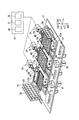
- FIG. 2 is a perspective view of the inside of the culture unit 14.
- the tube 38 is omitted.
- the control unit 11 is shown.
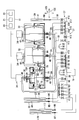
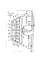
- FIG. 3 is a schematic view seen from above the inside of the culture unit 14.
- the holding plates 42 on the upper surfaces of the first bag holding part 31, the second bag holding part 32 and the third bag holding part 33 are omitted.
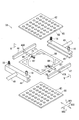
- FIG. 4 is an exploded perspective view of the third bag holding part 33.
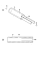
- 5A to 5C are cross-sectional views showing a cut surface VV of the culture bag 70.
- FIG. FIG. 6 is a schematic view of the first bag holding unit 31 for explaining the concentration device 120.
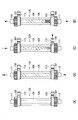
- 7A to 7D are schematic views of the concentrating device 120.
- FIG. 8 is a perspective view of the weight detection unit 23 and the bearing unit 24.
- FIG. 9A is a perspective view of the tube 99.
- FIG. 9B is a schematic view of a cross section of the tube 99 taken along the cutting plane IX-IX.
- FIG. 10 is an enlarged cross-sectional view showing a cut surface VV of the culture bag 70.
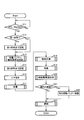
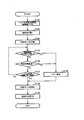
- FIG. 11 is a flowchart of the cell culture method.
- FIG. 12 is a schematic diagram for explaining the first posture of the first bag holding unit 31.
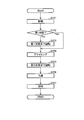
- FIG. 13 is a flowchart of the liquid supply step.
- FIG. 14 is a schematic diagram for explaining the third posture of the first bag holding portion 31.
- FIG. 15 is a cross-sectional view showing a cut surface VV of the culture bag 70 when the first bag holding portion 31 is in the third posture.
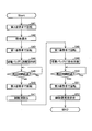
- FIG. 16 is a flowchart of the culture step.
- FIG. 17A is a cross-sectional view showing a cut surface VV of the culture bag 70 when the first bag holding portion 31 is in the first posture.
- FIG. 17B is a cross-sectional view showing a cut surface VV of the culture bag 70 when the first bag holding portion 31 is in the fourth posture.
- FIG. 18 is a schematic diagram for explaining the fourth posture of the first bag holding portion 31.
- FIG. 19 is a flowchart of the medium exchange step.
- FIG. 20 is a schematic diagram for explaining the second posture of the first bag holding unit 31.
- FIG. 21 is a cross-sectional view showing a cut surface VV of the culture bag 70 when the first bag holding portion 31 is in the second posture.
- FIG. 22 is a flowchart of the liquid discharging step.
- FIG. 23 is a flowchart of the cell suspension recovery step.
- FIG. 24 is a schematic diagram for explaining the first bag holding portion 31 in the third posture in the reverse direction.
- FIG. 25 is a cross-sectional view showing a cut surface VV of the culture bag 70 when the first bag holding portion 31 is in the third posture in the reverse direction.
- FIG. 26 is a flowchart of the cell suspension concentration step.
- the culture apparatus 10 includes a control unit 11, a refrigerated storage unit 12, a room temperature storage unit 13, and two culture units 14.
- the refrigerated storage unit 12 and the room temperature storage unit 13 are provided outside the culture unit 14.
- the two culture parts 14 are divided
- the control unit 11 includes a display 15.
- the display 15 is disposed on the front surface of the culture apparatus 10.
- the control unit 11 has a data input unit (not shown), and various conditions relating to cell culture are input to the control unit 11 through the data input unit.
- the culture apparatus 10 is an apparatus for automatically culturing cells according to a program input to the control unit 11 and stored.
- a vertical direction 101 is defined along the top and bottom in FIG. 1
- a horizontal direction 102 is defined along the left and right in FIG. 1
- a vertical direction 103 is defined along the vertical direction.
- the control unit 11 includes a rotation control unit 20, a culture control unit 21, and a supply / discharge control unit 22.
- the rotation control unit 20, the culture control unit 21, and the supply / exhaust control unit 22 are arithmetic devices for controlling the operation of each control target, and store programs and information in advance.
- the culture control unit 21 outputs control information to the rotation control unit 20 and the supply / discharge control unit 22. Further, the culture control unit 21 outputs control information for controlling the environmental temperature of the culture unit 14.
- the rotation control unit 20 is electrically connected to the rotation mechanism 34 and outputs control information for controlling the driving of the rotation mechanism 34.
- the supply / discharge control unit 22 is connected to the liquid supply / discharge mechanism 37, and includes control information for driving each drive unit of the liquid supply / discharge mechanism 37, that is, the supply pump 91, the discharge pump 92, and the valves V1 to V18. Output.
- the refrigerated storage unit 12 is a housing in which a shelf for placing a container storing a reagent or a medium is formed.
- a door that can open and close an opening provided on the front surface of the housing is provided.
- save part 12 is what is called a refrigerator provided with the cooling mechanism not shown.
- the room temperature storage unit 13 is a housing having a shelf for placing a container storing a reagent or a medium therein.
- the container placed inside the refrigerated storage unit 12 and the room temperature storage unit 13 can store a reagent or a medium in a liquid-tight manner.
- Examples of the container include a bag, a bottle, and a cassette.
- Each container is connected to a tube or the like so that the liquid inside can be discharged, and the liquid stored by the liquid supply / discharge mechanism 37 can flow out.
- the culture unit 14 is a space formed inside the culture device 10, and the space is partitioned by a housing frame of the culture device 10 and a tray 17 (see FIG. 2).
- the tray 17 can be pulled out from the front surface of the culture apparatus 10. By pulling out the tray 17, the culture unit 14 is opened, and each component provided in the culture unit 14 can be accessed.
- the culture unit 14 can be maintained at a predetermined temperature and CO 2 concentration. Although not shown in each figure, the culture unit 14 is provided with a heating device and a CO 2 supply device. The culture unit 14 is provided with a temperature sensor and a CO 2 concentration sensor. The culture control unit 21 drives the heating device and the CO 2 supply device so that the inside of the culture unit 14 is set to the set temperature and CO 2 concentration based on the outputs of the temperature sensor and the CO 2 concentration sensor. In cell culture, the culture unit 14 can be maintained in an environment of 37 ° C. and 5% CO 2 , for example.
- the tray 17 is provided with a first bag holding portion 31, a second bag holding portion 32, and a third bag holding portion 33 side by side in the left-right direction 102.
- a rotation mechanism 34 is provided behind the first bag holding portion 31 in the front-rear direction 103.
- the first bag holding unit 31 is rotated to a predetermined rotation posture by the rotation mechanism 34.
- a rotation mechanism 34 is provided behind the second bag holding part 32 in the front-rear direction 103, and a rotation mechanism 34 is provided behind the third bag holding part 33 in the front-rear direction 103.
- a liquid supply / discharge mechanism 37 is provided on the front side of the tray 17.
- a concentrating device support portion 104 is provided that is connected to the first bag holding portion 31 so as to be rotatable coaxially with the first bag holding portion 31.
- container storage portions 27 and 28 are provided on the left side of the left-right direction 102 of the tray 17, and a container storage portion 29 is provided on the right side.
- the first bag holding unit 31, the second bag holding unit 32, and the third bag holding unit 33 are basically the same except that their arrangement and dimensions are different. A detailed configuration will be described as an example.
- the external shape and dimension of the 1st bag holding part 31, the 2nd bag holding part 32, and the 3rd bag holding part 33 are designed according to the external shape of the culture
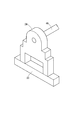
- the third bag holding portion 33 includes holding plates 42 and 43, holders 44 and 45, spacers 46 and 47, and rotating shafts 48 and 49.
- the holding plates 42 and 43 are rectangular flat plates.
- the holding plates 42 and 43 are formed with a plurality of holes penetrating in the thickness direction. This hole is for increasing the heat conduction from the gas in the culture unit 14 to the culture bag 90 held between the holding plates 42 and 43.
- the holding plates 42 and 43 are arranged to face each other.
- the surfaces facing each other in the holding plates 42 and 43 are support surfaces 65 and 66.
- Spacers 46 and 47 are arranged between a pair of opposing edges between the holding plates 42 and 43 where the ports 73 and 74 of the culture bag 90 (an example of a culture vessel) are arranged.
- the spacers 46 and 47 are for maintaining the distance between the holding plates 42 and 43.
- Each of the spacers 46 and 47 has a quadrangular prism shape.
- the lengths of the spacers 46 and 47 in the longitudinal direction are substantially the same as the lengths of the pair of edges of the holding plates 42 and 43.
- the spacers 46 and 47 have a constant cross-sectional shape in the longitudinal direction. In the center in the longitudinal direction of the spacers 46 and 47, recesses 46A and 47A that are recessed in a direction orthogonal to the longitudinal direction are formed.
- the recesses 46A and 47A are spaces into which the tubes 99 of the culture bag 90 are respectively inserted.
- the spacers 46 and 47 may be formed integrally with one of the holding plates 42 and 43.
- a distance sensor 67 is disposed on the spacer 47.
- a magnet 68 is disposed on the holding plate 42 in contact with the spacer 47 so as to face the distance sensor 67.
- the distance sensor 67 outputs a voltage corresponding to the magnetic flux density from the magnet 68, and for example, a Hall element is used. If the holding plates 42 and 43 are in a normal state holding the culture bag, the distance between the holding plate 42 and the spacer 47 is constant, so the output of the distance sensor 67 is also constant. When the amount of liquid flowing into the culture bag is large and the culture bag is expanded and the holding plates 42 and 43 are bent so as to be pushed away from each other, the distance between the holding plate 42 and the spacer 47 increases. Detects the magnetic flux density of the magnet 68, and the output of the distance sensor 67 changes.
- the control unit 11 stores a threshold value in advance. This threshold value is for determining that the distance between the holding plate 42 and the spacer 47 has become larger than a certain distance.
- the control unit 11 can determine that the distance between the holding plate 42 and the spacer 47 has become larger than a certain value by comparing the output of the distance sensor 67 with a threshold value.
- the distance sensor 67 may be provided not on the spacer 47 but on the spacer 46, or may be provided on both the spacers 46 and 47. Further, the magnet 68 may be provided on any one of the holding plates 42 and 43 as long as the magnetic flux can be detected by the distance sensor 67.
- the arrangement of the distance sensor 67 and the magnet 68 is relative, and the arrangement of the distance sensor 67 and the magnet 68 may be interchanged. Further, the distance sensor 67 and the magnet 68 may be arranged to face the holding plates 42 and 43, respectively.
- the holders 44 and 45 hold the holding plates 42 and 43 with the spacers 46 and 47 interposed therebetween so as to hold them together.
- the holders 44 and 45 are elongated members having a U-shaped cross section in the horizontal direction, and the edge portions of the holding plates 42 and 43 with the spacers 46 and 47 interposed are inserted inside the U-shaped shape in the horizontal direction.
- the edges of the holding plates 42 and 43 inserted into the holders 44 and 45 are a pair of edges where the spacers 46 and 47 are not interposed.
- Screw holes are formed on both ends in the longitudinal direction of the holders 44 and 45, and the screws 18 are screwed into the screw holes. The tip of the screw 18 protrudes to the inside of the horizontal U-shaped shape of the holders 44 and 45.
- the holders 44, 45 may be configured integrally with one of the holding plates 42 and 43. Further, the holding plates 42 and 43 may be rotatably connected like one hinge by one of the holders 44 and 45.
- the holders 44 and 45 are respectively provided with rotating shafts 48 and 49 that protrude from the vicinity of the center in the longitudinal direction in the opposite direction to the side on which the holding plates 42 and 43 are held.
- the rotating shafts 48 and 49 extend coaxially in a state where the holders 44 and 45 hold the holding plates 42 and 43.
- the direction in which the rotation shafts 48 and 49 extend is parallel to the support surfaces 65 and 66 of the holding plates 42 and 43.
- the third bag holding portion 33 when the third bag holding portion 33 has the support surface 66 below the support surface 65 and the support surfaces 65, 66 are in the horizontal direction, the third bag When no liquid is contained in the culture bag 90 supported by the holding unit 33, the culture bag 90 is mainly in contact with the support surface 66. At this time, the distance between the support surfaces 65 and 66 is the distance D1. As shown in FIG. 5 (B), the culture bag 90 is such that the holding plates 42 and 43 are not bent even if the culture bag 90 is inflated by the liquid to be stored and comes into contact with the support surfaces 65 and 66. A volume of liquid is introduced. Such an amount of liquid is set in advance as the amount of liquid that can be stored in the culture bag 90. As shown in FIG.
- first bag holding unit 31 and the second bag holding unit 32 are not described in detail with reference to the drawings. However, like the third bag holding unit 33, a holding plate holder and a spacer are provided. *
- the concentrating device support portion 104 is disposed behind the first bag holding portion 31 in the front-rear direction 103.
- the concentrating device support portion 104 is integrally connected to the first bag holding portion 31. Therefore, the concentrating device support portion 104 rotates integrally with the first bag holding portion 31 around the rotation shafts 48 and 49.
- the concentrator support unit 104 supports the concentrator 120.
- the concentrating device 120 supported by the concentrating device support section 104 is configured so that the inflow port 110 and the first outflow port 111 face the directions intersecting with the rotation axes of the rotation shafts 48 and 49 (directions orthogonal to each other in this embodiment). Placed in.
- the positions of the inflow port 110 and the first outflow port 111 in the vertical direction 101 change. Further, the inflow port 110 and the first outflow port 111 of the concentrator 120 supported by the concentrator support unit 104 extend in the direction in which each of the ports 73 and 74 of the culture bag 70 held by the first bag holding unit 31 extends. The extending direction matches.
- the first bag holding unit 31, the second bag holding unit 32, the third bag holding unit 33, and the concentrating device support unit 104 are arranged at the rotating first position.
- openings 17A are formed at three locations.
- a pair of bearing portions 24 are respectively arranged in front and rear in the front-rear direction 103 of each opening 17A.
- the pair of bearing portions 24 are configured so that the rotation axes 48 and 49 of the first bag holding portion 31, the second bag holding portion 32, the third bag holding portion 33, and the concentration device support portion 104 are along the front-rear direction 103.
- Each is supported rotatably. Thereby, each holding plate 42 and 43 of the 1st bag holding
- each bearing portion 24 is loaded on each weight detection portion 23 provided on the tray 17. Cultures held in the corresponding bag holding part and the corresponding bag holding part by the pair of weight detection parts 23 corresponding to the first bag holding part 31, the second bag holding part 32, or the third bag holding part 33, respectively. The weights of the bag and the bearing portion 24 are detected.
- the weight detection unit 23 for example, a load cell that converts a force (weight) applied to the weight detection unit 23 into an electrical signal is used.
- a rotation mechanism 34 is provided behind each bearing portion 24 in the front-rear direction 103.
- the rotating mechanism 34 includes the rotating shaft support 16 and a stepping motor (not shown).
- the rotating shaft support portion 16 extends rearward in the front-rear direction 103 and is coaxially connected to the rotating shaft 49 supported by each bearing portion 24.
- the stepping motor is supplied with electric power from a power source. Further, the stepping motor and the rotating shaft support portion 16 are driven and transmitted by a known reduction gear or the like. When electric power based on a control signal output from the rotation control unit 20 is supplied to the stepping motor, the rotation shaft support unit 16 rotates by a predetermined rotation angle.
- the origin position that is, the support surfaces 65 and 66 of the holding plates 42 and 43 of the first bag holding part 31, the second bag holding part 32, and the third bag holding part 33 are aligned along the horizontal direction.
- a sensor may be provided for detecting a rotational position that is in a state. Based on the output of this sensor, the rotation control unit 20 can drive the stepping motor so that the support surfaces 65 and 66 are in a state along the horizontal direction. Similarly, the stepping motor can be driven so that the inflow port 110 and the first outflow port 111 of the concentrator 120 extend in the horizontal direction.
- the stepping motor is an example of a drive source for the rotation mechanism 34, and other drive sources such as a DC motor having an encoder capable of detecting the rotation amount may be employed instead of the stepping motor.
- the rotational position of the drive source may be detected by other detection means such as a resolver, or a sensor that can directly detect the rotational position of the first bag holding unit 31 or the like may be provided.
- the liquid supply / discharge mechanism 37 has a supply pump 91, a discharge pump 92, and a plurality of valves V1 to V18.
- a known pump capable of feeding the liquid in the tube is adopted.
- a so-called tube pump that feeds liquid by handling a soft tube with a rotating roller can be cited.
- Electric power is supplied to the supply pump 91 and the discharge pump 92 from a power source.
- the supply / discharge control unit 22 can drive the supply pump 91 and the discharge pump 92 for a certain period of time by controlling the power supplied to the supply pump 91 and the discharge pump 92.
- the plurality of valves V1 to V18 are roughly classified into valves V1 to V11 related to the supply pump 91 and valves V12 to V18 related to the discharge pump 92.
- the supply pump 91 and the valves V1 to V11 are the liquid supply mechanism 81 in the liquid supply / discharge mechanism 37
- the discharge pump 92 and the valves V12 to V18 are the liquid discharge mechanism 82 in the liquid supply / discharge mechanism 37.
- Each of the valves V1 to V18 is switched on / off based on a control signal output from the supply / discharge control unit 22. By turning on / off each of the valves V1 to V18, the flow of the liquid in each tube 38 connected to the culture bag or the like can be changed.
- the valves V1 to V18 for example, electromagnetic valves are employed.
- the culture circuit includes three culture bags 70, 80, 90, two server bags 39, 40, a collection bag 41, a concentration device 120, a refrigerated storage unit 12, or a room temperature storage unit. 13 and storage tubes 116 and 117, and a plurality of tubes 38 that connect the reservoirs 116 and 117 so that a liquid can flow therethrough.
- the culture bag 70 is installed in the first bag holding unit 31.
- the culture bag 80 is installed in the second bag holding part 32.
- the culture bag 90 is installed in the third bag holding part 33.
- the concentrator 120 is installed on the concentrator support unit 104.
- the collection bag 41 is installed in the culture unit 14. Since each culture bag 70, 80, 90 has the same configuration except that the culture bag 70 has a smaller capacity than the culture bags 80, 90, the detailed configuration will be described below using the culture bag 90 as an example.
- the culture bag 90 is formed in a bag shape by bonding the peripheral edges of two rectangular sheets made of synthetic resin by a known method such as heat welding.
- Synthetic resin tubes 99 are arranged in the vicinity of the center of a pair of end portions 77 and 78 facing each other in the two rectangular sheets.
- the portion located in the inner space 75 of the culture bag 90 has edges 87 and 88 from the end located in the inner space 75 of the culture bag 90.
- a notch 105 is formed toward the top. As shown in FIG.
- the notch 105 is located at a position not facing the inner surfaces 71 and 72 that define the inner space 75 of the culture bag 90, that is, other than the pair of end portions 77 and 78 in the two rectangular sheets. It is located at the point facing the end. Even if a negative pressure is generated in the internal space 75 when the liquid flows out from the culture bag 90 and the inner surfaces 71 and 72 approach each other, the tube 99 is located between the inner surfaces 71 and 72 in the vicinity of the tube 99. By existing, it becomes difficult for the inner surfaces 71 and 72 to contact each other.
- the notch 105 is formed in the tube 99 at a location not facing the inner surfaces 71, 72, so that the liquid remaining in the vicinity of the edges 87, 88 of the inner space 75 through the notch 105 passes through the inner space of the tube 99. Can flow into.
- the internal space 75 of the culture bag 90 communicates with the outside through the internal space of the tube 99. That is, the ports 73 and 74 are formed by each tube 99.
- the edges 87 and 88 on which the tube 99 is disposed are tapered so that the distance between the edges 87 and 88 decreases as the distance from the ports 73 and 74 increases.
- the edges 87 and 88 have a shape that bulges toward the outside of the culture bag 90 toward the center where the tube 99 is disposed.
- the tube 99 extends in a direction orthogonal to the rotation shafts 48 and 49. That is, the ports 73 and 74 extend in a direction orthogonal to the rotation shafts 48 and 49.
- the synthetic resin sheet used for the culture bag 90 is flexible and has a bending rigidity capable of maintaining the shape of the bag when the culture medium is added.
- low density polyethylene ultrahigh molecular weight polyethylene, cyclic Examples thereof include polyolefin resins or those having a laminate structure with these and other materials.
- the inner surfaces 71 and 72 of the culture bag 90 have cell adhesion suitable for culturing adhesive cells.
- the inner surfaces 71 and 72 have their cell adhesive functional groups exposed, for example, by plasma treatment.
- the cell adhesive functional group include an amino group, an amine group, a hydroxyl group, a sulfone group, a sulfene group, a sulfine group, an ether group, a carboxyl group, and a carbonyl group. Of these, amino groups and carboxyl groups, which have high adhesion to cells, are preferred.
- the server bags 39 and 40, the recovery bag 41, and the storage containers 116 and 117 shown in FIG. 3 are formed in a bag shape by pasting synthetic resin sheets, and have at least one port 94 to 98. .
- the server bags 39 and 40 are for storing a culture medium.
- the collection bag 41 is for collecting the cell suspension.
- the storage containers 116 and 117 are for storing a stripping solution and a priming solution.
- a known container capable of storing a culture medium and a cell suspension can be adopted in addition to a known bag.
- tubes 38 are connected to the ports of the culture bags 70, 80, 90, the server bags 39, 40, the collection bag 41, and the storage containers 116, 117, respectively.
- Each tube 38 connected to one port 73 of each of the culture bags 70, 80, 90, the tube 38 connected to the inflow port 110 of the concentrator 120, and the ports 94, 95 of the server bags 39, 40 are connected.
- the tubes 38 and the tubes 38 connected to the ports 97 and 98 of the storage containers 116 and 117 are extended to the supply pump 91.
- Each of these tubes 38 is collected into one tube 38 via a connector before reaching the supply pump 91 to form a liquid supply circuit.
- each of these tubes 38 is passed through the valves V6 to V11 before being combined into one tube 38, and an open state in which the liquid can flow through the internal space of the tubes 38 by the valves V6 to V11. And a closed state in which the liquid cannot flow.
- a tube 38 connected to 96 extends to a discharge pump 92.
- These tubes 38 are combined into a single tube 38 via a connector before reaching the discharge pump 92 to form a liquid discharge circuit.
- Each of these tubes 38 is passed through valves V12 and V14 to V18 before being combined into one tube 38, and the liquid flows through the internal space of the tube 38 by the valves V12 and V14 to V18. It is possible to change between a possible open state and a closed state where liquid cannot flow.
- the tubes 38 communicating with the supply pump 91 are branched again and connected to bags and containers placed in the refrigerated storage unit 12 or the room temperature storage unit 13 through valves V1 to V5. These bags and containers store reagents such as cell suspensions, culture media, and stripping solutions.
- a tube 38 communicating with the discharge pump 92 is connected to the waste liquid container 19.
- the concentrating device 120 includes a main body 106, a cap 107, a cap 108, and a hollow fiber bundle 109.
- the main body 106 has a substantially cylindrical shape.
- the main body 106 is open on both sides in the axial direction (the direction along the vertical direction in FIG. 7A).
- a cap 107 and a cap 108 are screwed into each opening of the main body 106.
- the cap 107 is formed with an inflow port 110 that communicates the internal space and the external space of the concentrator 120 so as to extend along the axial direction of the main body 106.
- the cap 108 is formed with a first outflow port 111 that communicates the internal space and the external space of the concentrator 120 so as to extend along the axial direction of the main body 106.
- a pair of hollow fiber supports (not shown) are provided, and supported by the pair of hollow fiber supports, a hollow fiber bundle 109 is disposed in the internal space of the main body 106. Yes. Both ends of the hollow fiber bundle 109 are arranged near the opening of the main body 106.
- the hollow fiber support supports both ends of the hollow fiber bundle 109 and separates both ends of the hollow fiber bundle 109 from the internal space of the main body 106 in a liquid-tight manner. Therefore, the liquid that has flowed into the internal space of the main body 106 through the inflow port 110 of the cap 107 flows into one end of the hollow core bundle 114 and does not flow into the space defined by the pair of hollow fiber supports in the internal space of the main body 106.
- the liquid flowing out from the other end of the hollow fiber bundle 109 flows out from the first outflow port 111 of the cap 108 to the outside, and the first outflow from the space defined by the pair of hollow fiber supports in the internal space of the main body 106. The liquid does not flow out to the port 111.
- a second outflow port 112 extends to the main body 106 in a direction orthogonal to the axial direction of the main body 106 (the direction along the vertical direction in FIG. 7) on the side where the cap 108 is screwed.
- a port 113 extends in a direction orthogonal to the axial direction of the main body 106 on the side to be joined.
- the second outflow port 112 and the port 113 communicate the space defined by the pair of hollow fiber supports in the internal space of the main body 106 and the outside of the main body 106.
- the port 113 is sealed in this embodiment.
- the tube 38 described above is connected to the inflow port 110, the first outflow port 111, and the second outflow port 112.
- the hollow fiber bundle 109 is a hollow fiber bundle in which a dialysis membrane is formed in a tubular shape.
- the hollow fiber is open at each end.
- the hollow fiber raw material include triacetate and polyethersulfone.
- the thickness, film thickness, pore diameter, length, type, and the like of the hollow fiber are appropriately set according to conditions such as the size of cells to be filtered in the concentrator 120.
- Cell culture method using culture apparatus 10 the cell culture method using the culture apparatus 10 is demonstrated.
- Cell culture using the culture apparatus 10 can be performed by arbitrarily selecting any one or a plurality of culture bags 70, 80, and 90.
- a cell culture method using only the culture bag 70 will be described. Is explained.
- the cell culture method using the culture apparatus 10 includes the following steps. (1) A culture step of amplifying cells in the culture bag 70. (2) A medium replacement step for replacing the medium in the culture bag 70. (3) A cell suspension recovery step of recovering the cell suspension in the culture bag 70. (4) A cell suspension concentration step of concentrating the cell suspension in the server bag 40.
- a culture circuit is set in the culture apparatus 10 in advance. Specifically, as shown in FIG. 3, the culture bags 70, 80, and 90 are set in the first bag holding unit 31, the second bag holding unit 32, and the third bag holding unit 33, respectively.
- the concentrator support unit 104 is set, the server bags 39 and 40 are held in the container storage units 27 and 28, respectively, and the collection bag 41 is held in the container storage unit 29. Further, the storage containers 116 and 117 are held in the refrigerated storage unit 12 or the room temperature storage unit 13.
- each tube 38 of the circuit is set in each valve V1 to V18, supply pump 91, and discharge pump 92.
- a user performs settings in advance so that a culture step, a medium replacement step, a culture step, a cell suspension concentration step, and a cell suspension collection step are sequentially performed.
- Various settings such as the culture time in the culture step, the medium exchange amount in the medium exchange step, the concentration time and medium supply amount in the cell suspension concentration step, and the reaction time with the stripping solution in the cell suspension recovery step are also set in advance by the user.
- the culture control unit 21 outputs first information including various setting information in the culture step, outputs second information including various setting information in the medium replacement step, and includes various setting information in the cell suspension recovery step. 3 Output information.
- the culture control unit 21 outputs various setting information in the cell suspension concentration step.
- the rotation control unit 20 controls the driving of the rotation mechanism 34 based on each information output from the culture control unit 21.
- the supply / discharge control unit 22 controls driving of the liquid supply / discharge mechanism 37 (the liquid supply mechanism 81 and the liquid discharge mechanism 82) based on each information output from the culture control unit 21.
- the culture unit 14 in the culture apparatus 10 performs a preliminary operation when the culture control unit 21 receives an input for starting culture. Specifically, the temperature of the culture unit 14 is adjusted to 37 ° C. and the concentration of carbon dioxide is adjusted to 5% by driving the heating device and the CO 2 supply device based on the control information from the culture control unit 21. (Step S11). Subsequently, the rotation control unit 20 determines whether or not the first bag holding unit 31 is in the first posture (step S12). When the first bag holding unit 31 is not in the first posture, that is, when the rotation control unit 20 determines that the stepping motor in the rotation mechanism 34 is not at the origin position (step S12: No), the rotation control unit 20 performs the rotation mechanism 34.
- step S13 the 1st bag holding
- step S12: Yes the rotation control part 20 does not drive the rotation mechanism 34.
- the support surfaces 65 and 66 in the first posture need only be substantially along the horizontal direction and do not need to be strictly along the horizontal direction.
- Each valve V1 to V18 closes the tube 38.
- the supply / discharge control unit 22 supplies the cell suspension to the culture bag 70 (step S14).
- the cell suspension is supplied to the culture bag 70 according to the liquid supply step.
- the weight detection unit 23 detects the weight of the culture bag 70 and the first bag holding unit 31. To do.
- the control unit 11 sets a first reference value (step S121). Subsequently, the control unit 11 calculates a value obtained by adding the weight of the cell suspension to be supplied to the culture bag 70 to the first reference value as the first target value.
- the cell suspension is supplied to the culture bag 70. However, step S14 may be omitted and the culture bag 70 may be manually filled with the cell suspension in advance.
- the supply / discharge control unit 22 drives the liquid supply mechanism 81 to supply liquid to the culture bag 70 when the first bag holding unit 31 is stopped in the first posture. Specifically, the valves V6 and V9 are opened (step S122). Subsequently, the supply pump 91 is driven (step S123).
- the server bag 40 stores a cell suspension containing cells to be cultured in advance. Therefore, the cell suspension is supplied from the server bag 40 to the culture bag 70 through the port 73. While the cell suspension is being supplied to the culture bag 70, that is, while the supply pump 91 is being driven, the control unit 11 monitors whether or not the distance sensor 67 has exceeded a preset threshold value. (Step S124).
- step S124 determines that the output value of the distance sensor 67 has exceeded the threshold value (step S124: Yes)
- the control unit 11 generates a buzzer sound or turns on a light to issue an alarm (step S126). Then, the supply / discharge control unit 22 stops the supply pump 91 (step S128).
- the control unit 11 monitors whether or not a preset time has elapsed since the supply pump 91 was driven (step S125). The time is set longer than the time sufficient for the supply pump 91 to supply the maximum amount of liquid to the culture bag 70.
- the control unit 11 determines that a preset time has elapsed since the supply pump 91 is driven (step S125: Yes)
- it issues an alarm in the same manner as described above step S126
- the supply / discharge control unit 22 Then, the supply pump 91 is stopped (step S128).
- the control unit 11 monitors whether or not the output value of the weight detection unit 23 has reached the first target value while the supply pump 91 is being driven (step S127).
- the control unit 11 determines that the output value of the weight detection unit 23 has reached the first target value (step S127: Yes)
- the supply / discharge control unit 22 stops the supply pump 91 (step S128).
- the valves V6 and V9 are closed (step S129). Thereby, the supply of the cell suspension (liquid supply step) to the culture bag 70 is completed (step S14).
- the rotation control unit 20 drives the rotation mechanism 34 to rotate the first bag holding unit 31 by 90 degrees counterclockwise.
- the first bag holding portion 31 has a third posture in which the support surfaces 65 and 66 are along the vertical direction, the port 74 is upward, and the port 73 is downward.
- Step S15 In the culture bag 70 held by the first bag holding portion 31 in the third posture, the gas that has entered the internal space 75 is collected at the edge 88 of the port 74 located above. Since the edge 88 is tapered toward the port 74, the gas moving along the edge 88 collects at the port 74.
- the support surfaces 65 and 66 in the third posture need only be substantially along the vertical direction, and are not necessarily strictly along the vertical direction.
- the supply / discharge control part 22 After the 1st bag holding
- the culture control unit 21 sequentially performs a culture step (step S17), a medium replacement step (step S18), a culture step (step S19), and a cell suspension recovery step (step S20). Details of each step will be described later.
- a culture step step S17
- a medium replacement step step S18
- a culture step step S19
- a cell suspension recovery step step S20. Details of each step will be described later.
- the culture step When the culture step is performed, the culture control unit 21 outputs the first information to the rotation control unit 20 and the supply / discharge control unit 22. As shown in FIGS. 12 and 16, the rotation control unit 20 drives the rotation mechanism 34 to place the first bag holding unit 31 in the first posture (step S24).
- the inner surface 71 is upward and the inner surface 72 is downward.
- a cell suspension containing cells to be cultured and a medium is stored in the internal space 75 of the culture bag 70. In the internal space 75, the cells descend the cell suspension by gravity and contact the inner surface 72. Thereby, the cells adhere to the inner surface 72 and are cultured.
- the rotation control unit 20 maintains the first bag holding unit 31 in the first posture until a preset time has elapsed (step S25: No). After a preset time has elapsed (step S25: Yes), the rotation control unit 20 drives the rotation mechanism 34 to rotate the first bag holding unit 31 clockwise by 180 degrees as viewed from the front of the culture apparatus 10. (Step S26). Accordingly, as shown in FIGS. 17B and 18, the first bag holding portion 31 has the support surfaces 65 and 66 along the horizontal direction, and the inner surface 72 of the culture bag 70 is upward, The fourth posture is such that the inner surface 71 is downward.
- the culture bag 70 when the inner surface 72 is on the upper side and the inner surface 71 is on the lower side, cells contained in the cell suspension stored in the inner space 75 of the culture bag 70 and not attached to the inner surface 72 are The inside of the cell suspension is lowered by gravity and contacts the inner surface 71. Thereby, the cells adhere to the inner surface 71 and are cultured.
- the rotation control unit 20 maintains the first bag holding unit 31 in the fourth posture until a preset time has elapsed (step S27: No). When the preset time has elapsed (step S27: Yes), the culture step ends.
- the medium exchange step is an example of a solution exchange step.
- the culture control unit 21 outputs the second information to the rotation control unit 20 and the supply / discharge control unit 22.
- the supply pump 91 is driven by opening the valve V1 and the valve V7 through which the tube 38 connected to the storage container 117 for storing the fresh medium stored in the refrigerated storage unit 12 or the room temperature storage unit 13 is passed, A fresh medium is supplied to the server bag 39.
- the supply / discharge control unit 22 stops the supply pump 91, closes the valve V1, and opens the valve V6.
- the supply / discharge control unit 22 opens the valves V6 and V7 through which the tubes 38 connected to the server bags 39 and 40 are opened, drives the supply pump 91 in the reverse direction, and supplies fresh medium to the server bag 40. Supply. Thereafter, the supply / discharge control unit 22 stops the supply pump 91 and closes the valves V6 and V7. The fresh medium is held in the server bag 40 to be heated to 37 ° C.
- the rotation control unit 20 drives the rotation mechanism 34 to rotate the first bag holding unit 31 in the first posture 30 degrees clockwise as viewed from the front of the culture apparatus 10.
- the first bag holding portion 31 has an angle that the support surfaces 65 and 66 form an acute angle with respect to the horizontal direction is 30 degrees, and the port 73 is on the upper side.
- the second posture 74 is at the lower side (step S31).
- the angle at which the support surfaces 65 and 66 form an acute angle with respect to the horizontal direction is not limited to 30 degrees, and the second posture is arbitrarily set unless the support surfaces 65 and 66 are along the horizontal direction and the vertical direction. It's okay.
- the angle at which the support surfaces 65 and 66 form an acute angle with respect to the horizontal direction is not less than 20 degrees and not more than 70 degrees. More preferably, it is 30 degrees or more and 60 degrees or less.
- the supply / discharge control unit 22 discharges the medium from the culture bag 70 (step S32).
- the medium is discharged from the culture bag 70 according to the liquid supply step.
- the weight detection unit 23 detects the weights of the culture bag 70 and the first bag holding unit 31. To do.
- the control unit 11 sets a second reference value (step S141). Subsequently, the control unit 11 calculates a value obtained by subtracting the weight of the medium to be discharged from the culture bag 70 from the second reference value as the second target value.
- the supply / discharge control unit 22 drives the liquid discharge mechanism 82 to discharge the culture medium from the culture bag 70 when the first bag holding unit 31 is stopped in the second posture. More specifically, the valves V13 and V15 are opened (step S142). Subsequently, the discharge pump 92 is driven (step S143). The controller 11 monitors whether or not a preset time has elapsed since the discharge pump 92 was driven (step S144). The time is set longer than the time sufficient for the discharge pump 92 to discharge half of the liquid from the culture bag 70.
- step S144 When the control unit 11 determines that a preset time has elapsed since the discharge pump 92 is driven (step S144: Yes), the control unit 11 issues an alarm in the same manner as described above (step S145), and the supply / discharge control unit 22 Then, the discharge pump 92 is stopped (step S147).
- the control unit 11 monitors whether or not the output value of the weight detection unit 23 has reached the second target value while the discharge pump 92 is being driven (step S146).
- the control unit 11 determines that the output value of the weight detection unit 23 has reached the second target value (step S146: Yes)
- the supply / discharge control unit 22 stops the discharge pump 92 (step S147), and The valves V13 and V15 are closed (step S148).
- half of the culture medium stored in the culture bag 70 is discharged (liquid discharge step) from the internal space 75 of the culture bag 70 (step S32).
- the rotation control unit 20 drives the rotation mechanism 34 to place the first bag holding unit 31 in the first posture (step S33). ).
- bulb V6, V9 is made into an open state, and supply of the culture medium to the culture bag 70 is performed similarly to the liquid supply step mentioned above.
- the fresh culture medium stored in the server bag 40 is supplied to the culture bag 70 (step S34).
- the amount of fresh medium supplied to the culture bag 70 is the same as the amount discharged from the culture bag 70 previously, that is, half the amount of the medium stored in the internal space 75.
- the supply / discharge control unit 22 stops the supply pump 91 and closes the valves V6 and V9.
- the rotation control unit 20 drives the rotation mechanism 34 so that the first bag holding unit 31 in the first posture is counterclockwise as viewed from the front of the culture apparatus 10. Rotate 90 degrees. Accordingly, as shown in FIG. 14, the first bag holding portion 31 has a third posture in which the support surfaces 65 and 66 are along the vertical direction, the port 73 is below, and the port 74 is above. (Step S35). After the 1st bag holding
- step S36 gas is discharged
- step S18 gas is discharged
- the culture step (step S19) is performed in the same manner as described above.
- the medium exchange step and the culture step may be further repeated after the passage.
- the culture step repeated after the passage when the amount of cells increases, the cell suspension is transferred from the culture bag 70 to the culture bag 80, so that the culture bags 80, 90 having a larger capacity than the culture bag 70 are used. 90 may be moved.
- a cell suspension recovery step (step S20) and a cell suspension concentration step (step S23) are performed.
- the cell suspension recovery step is an example of a solution discharge step.
- the culture control unit 21 outputs the third information to the rotation control unit 20 and the supply / discharge control unit 22.
- the rotation control unit 20 drives the rotation mechanism 34 to rotate the first bag holding unit 31 in the fourth posture 90 degrees counterclockwise when viewed from the front of the culture apparatus 10.
- the first bag holding portion 31 has the support surfaces 65 and 66 along the vertical direction, the port 73 on the upper side, and the port 74 on the lower side.
- Three postures are assumed (step S41). In the present embodiment, as long as the support surfaces 65 and 66 of the first bag holding portion 31 are in the vertical direction, the third posture is possible regardless of which of the ports 73 and 74 is above or below. It is called.
- the medium is discharged from the culture bag 70.
- the supply / discharge control unit 22 drives the discharge pump 92 by opening the valves V13 and V15. Thereby, the whole amount of the culture medium stored in the culture bag 70 is discharged from the internal space 75 through the port 74 (step S42).
- the rotation control unit 20 drives the rotation mechanism 34 to place the first bag holding unit 31 in the third posture in the first posture (step S43).
- the stripping solution is supplied to the culture bag 70.
- the supply / discharge control unit 22 opens one of the valves V3 to V5 through which the tube 38 connected to the container for storing the stripping solution stored in the refrigerated storage unit 12 or the room temperature storage unit 13 and the valve V9 are opened.
- the supply pump 91 is driven.
- the stripping solution is supplied to the internal space 75 of the culture bag 70 through the port 73 (step S44).
- the supply / discharge control unit 22 stops the supply pump 91 and closes any of the valves V3 to V5 that are opened and V9.
- the rotation control unit 20 maintains the first bag holding unit 31 in the first posture until a preset time has elapsed (step S45: No).
- the stripping solution weakens the adhesion of the cells attached to the inner surfaces 71, 72 of the culture bag 70 to the inner surfaces 71, 72.
- the action of weakening cell adhesion to the inner surfaces 71 and 72 is appropriately set by the type and concentration of the stripping solution, the contact time with the inner surfaces 71 and 72, the posture of the first bag holding portion 31 and the like. It is realized by. Note that after the stripping solution is supplied to the culture bag 70, if necessary, the gas may be discharged from the internal space 75 of the culture bag 70 in the same manner as described above.
- step S45 the rotation control unit 20 drives the rotation mechanism 34 to rotate the first bag holding unit 31 counterclockwise 90 when viewed from the front of the culture apparatus 10. Is rotated to a third posture (step S46).
- step S46 After the 1st bag holding part 31 is made into the 3rd attitude
- the supply / discharge control unit 22 opens the valves V6 and V9 and drives the supply pump 91 in the reverse direction. Thereby, in the culture bag 70, the stripping solution is discharged from the internal space 75 to the waste liquid container 19 through the port 73 (step S47). After the entire amount of the stripping solution is discharged from the culture bag 70, the rotation control unit 20 drives the rotation mechanism 34 to rotate the first bag holding unit 31 90 degrees clockwise as viewed from the front of the culture device 10. To the first posture (step S48).
- the culture medium is supplied to the culture bag 70.
- the supply / discharge control unit 22 opens any one of the valves V3 to V5 through which the tube 38 connected to the container storing the medium stored in the refrigerated storage unit 12 or the room temperature storage unit 13 is passed, and the valve V9.
- the supply pump 91 is driven.
- a culture medium is supplied through the port 73 to the internal space 75 of the culture bag 70 (step S49).
- the supply / discharge control unit 22 stops the supply pump 91 and closes any of the valves V3 to V5 that are opened and V9.
- the rotation control unit 20 maintains the first bag holding unit 31 in the first posture until a preset time has elapsed (step S50).
- the cells attached to the inner surfaces 71 and 72 of the culture bag 70 are peeled off. Separation of cells from the inner surfaces 71 and 72 by the supply of the culture medium is realized by appropriately setting the flow rate of the culture medium, the posture of the first bag holding unit 31 and the like, and the leaving time. Note that after the medium is supplied to the culture bag 70, if necessary, the gas may be discharged from the internal space 75 of the culture bag 70 in the same manner as described above.
- step S50 the rotation control unit 20 drives the rotation mechanism 34 to rotate the first bag holding unit 31 counterclockwise by 90 degrees when viewed from the front of the culture apparatus 10.
- step S51 the third posture is set (step S51).
- emission of the cell suspension from the culture bag 70 is performed similarly to the liquid discharge step mentioned above.
- the supply / discharge control unit 22 opens the valves V6 and V9 and drives the supply pump 91 in the reverse direction. Thereby, in the culture bag 70, the cell suspension is discharged from the internal space 75 through the port 73 (step S52) and collected in the server bag 40. Thereby, a cell suspension collection step (Step S20) is completed.
- the method for concentrating a cell suspension using the concentrator 120 includes the following steps. (4-1) A moving step of moving the cell suspension from the culture bag 70 to the server bag 40. (4-2) A priming step of supplying a priming solution to the concentrator 120. (4-3) A filtration step of supplying the cell suspension to the concentrator 120. (4-4) A recovery step of recovering the cell suspension from the concentration device 120.
- the cell suspension is moved from the culture bag 70 to the server bag 40 (step S151).
- the moving step is executed in the cell suspension recovery step described above.
- the rotation control unit 20 determines whether or not the concentrator support unit 104 is in the first state (step S152).
- the first state is a state in which the axial direction of the main body 106 of the concentrator 120 is along the vertical direction, and the inflow port 110 is below the first discharge port 111 (see FIG. 7B).
- the rotation control unit 20 drives the rotation mechanism 34 to rotate the concentrator support unit 104 to the first posture (step S153).
- the axial direction of the main body 106 of the concentrating device 120 is not necessarily along the vertical direction.
- priming (step S154) is performed.
- the priming liquid is supplied to the concentrating device 120 supported by the concentrating device support portion 104 in the first state.
- the priming solution is, for example, a phosphate buffer solution.
- the supply / discharge control unit 22 opens the valves V8, V13, and V14, which are held in the refrigerated storage unit 12 or the room temperature storage unit 13 and connected to the storage container 116 for storing the priming liquid, The supply pump 91 is driven. Thereby, the priming liquid is supplied to the concentrating device 120 through the inflow port 110.
- the supply / discharge control unit 22 monitors whether or not a preset time has elapsed since the supply pump 91 is driven. As the time, a time longer than a time sufficient for the supply pump 91 to discharge the gas from the inside of the concentrator 120 is set. When the supply / discharge control unit 22 determines that a preset time has elapsed since the supply pump 91 was driven, the supply / discharge control unit 22 stops the supply pump 91 and closes the valves V2 and V13, V14. This completes the priming step.
- the rotation control unit 20 drives the rotation mechanism 34 to rotate the concentrator support unit 104 by 180 degrees (step S155).
- concentration device 120 will be in the 2nd state.
- the second state is a state in which the axial direction of the main body 106 of the concentrating device 120 is along the vertical direction, and the inflow port 110 is above the first discharge port 111. In the second state, the axial direction of the main body 106 of the concentrating device 120 is not necessarily along the vertical direction.
- a filtration step (step S156) is performed.
- the supply / discharge control unit 22 drives the supply pump 91 with the valves V6 and V12 open.
- the cell suspension is supplied from the server bag 40 to the concentration device 120 through the inflow port 110.
- the cell suspension supplied to the concentrating device 120 circulates inside the hollow fiber bundle 109, and the cells contained in the cell suspension settle below the inside of the hollow fiber bundle 109, and the first outflow port 111. It collects in the vicinity.
- a liquid such as a medium contained in the cell suspension flows out of the hollow fiber bundle 109 and out of the concentrator 120 through the second outflow port 112.
- the cell suspension that has flowed into the concentrating device 120 is maintained in a concentrated state in the hollow fiber bundle 109 and in the vicinity of the first outflow port 111.
- the supply / discharge control unit 22 stops the supply pump 91 and closes the valves V6 and V12. Thereby, a filtration step is complete
- finished step S156).
- a recovery step (step S157) is performed.
- the supply / exhaust control unit 22 opens the valve V1 connected to the storage container 117 for storing fresh medium stored in the refrigerated storage unit 12 or the room temperature storage unit 13, and the valves V14 and V18 and opens the supply pump 91. To drive.
- fresh medium is supplied to the concentrating device 120 through the inflow port 110.
- the concentrator 120 the fresh medium flowing through the hollow fiber bundle 109 flows out from the concentrator 120 to the collection bag 41 through the first discharge port 111 together with the concentrated cell suspension.
- recovery step is complete
- the concentrated cell suspension is flowed out to the collection bag 41, but may be flowed out to the culture bags 70, 80, 90.
- cell culture is performed in the culture bags 70, 80, 90 held by the bag holders 31, 32, 33 in the first posture.
- the first posture since the support surfaces 65 and 66 of the bag holding portions 31, 32 and 33 are substantially horizontal, one of the inner surfaces 71 and 72 of the culture bags 70, 80 and 90 is substantially horizontal. Kept in a state.
- the culture bags 70, 80, 90 are stably supported by the bag holders 31, 32, 33, and for example, adherent cells adhere to the inner surface 72 of the culture bags 70, 80, 90 and are cultured.
- the cell suspension flows out through the port 74.
- the third posture since the support surfaces of the bag holding portions 31, 32, 33 are along the substantially vertical direction, the inner surfaces 71, 72 of the culture bags 70, 80, 90 are held in a state along the substantially vertical direction. .
- the port 74 of the culture bag 70, 80, 90 is positioned below in the vertical direction, the cell suspension flows out of the internal space 75 of the culture bag 70, 80, 90 through the port 74 due to gravity.
- the culture medium is exchanged in the culture bags 70, 80, 90 held in the bag holders 31, 32, 33 in the second posture.
- the medium exchange for example, a part of the medium stored in the culture bags 70, 80, 90 is discharged.
- the inner surfaces 71, 72 of the culture bags 70, 80, 90 are not along either the horizontal direction or the vertical direction, so the port 74 of the culture bags 70, 80, 90 is positioned below the vertical direction.
- the culture medium flows out from the internal space 75 of the culture bags 70, 80, 90 through the port 74 due to gravity, but the deformation of the culture bags 70, 80, 90 due to gravity is smaller than that in the third posture.
- the possibility that the inner surfaces 71 and 72 are in contact with each other in the culture bags 70, 80, and 90 is reduced.
- the possibility of cells falling off from the inner surfaces 71, 72 of the culture bags 70, 80, 90 is reduced.
- the culture medium stored by culture bag 70,80,90 flows out through the port 74 of culture bag 70,80,90 located in the downward direction of a perpendicular direction. . Thereafter, the medium flows into the internal space 75 through the ports 73 of the culture bags 70, 80, 90 in the bag holding portions 31, 32, 33 in the first posture. Then, in the bag holders 31, 32, 33 in the second posture or the third posture, the liquid supply / discharge mechanism 37 sucks a predetermined amount through the ports 74 of the culture bags 70, 80, 90 positioned above in the vertical direction. Do.
- the culture bags 70, 80, 90 positioned in the vertical direction in the second posture or the third posture. Gas gathers in the vicinity of the port 74, and the gas is sucked out of the culture bags 70, 80, 90 through the port 74.
- the ports 73 and 74 formed in the culture bags 70, 80, and 90 extend along the direction orthogonal to the rotation shafts 48 and 49 when held in the bag holding portions 31, 32, and 33. The gas or liquid is efficiently flowed into and out of the culture bags 70, 80, 90.
- edges 87 and 88 that define the internal space 75 of the culture bags 70, 80, and 90 and where the ports 73 and 74 are disposed are held in the bag holding portions 31, 32, and 33.
- the rotary shafts 48 and 49 approach each other. For this reason, when the port 74 of the culture bag 70, 80, 90 is positioned above in the vertical direction, gas tends to gather toward the port 74 in the internal space 75 of the culture bag 70, 80, 90.
- the rotation control unit 20 sets the bag holding units 31, 32, and 33 to the first posture in accordance with the first information, and then the fourth posture in which the support surfaces 65 and 66 are rotated 180 degrees from the first posture.
- position for example, an adhesive cell adheres and culture
- the inner surfaces 72 of the culture bags 70, 80, 90 that faced upward in the vertical direction in the first posture face downward in the vertical direction.
- the inner surfaces 71 of the culture bags 70, 80, 90 that face downward in the vertical direction in the first posture face upward in the vertical direction.
- the adherent cells adhere and are cultured on the inner surface 71 where the adherent cells are difficult to adhere in the first posture.
- the supply / discharge control unit 22 holds the bag in the third posture in the liquid supply / discharge mechanism 37.
- the medium is allowed to flow out through the ports 74 of the culture bags 70, 80, 90 held in the parts 31, 32, 33.
- the rotation control unit 20 sets the bag holding units 31, 32, 33 to the first posture, and the supply / discharge control unit 22 supplies the first to the liquid supply / discharge mechanism 37.
- the stripping solution is caused to flow through the ports 73 of the culture bags 70, 80, 90 held by the bag holders 31, 32, 33 in the posture.
- the rotation control unit 20 sets the bag holding units 31, 32, and 33 to the third posture, and the supply / discharge control unit 22 supplies the liquid supply / discharge mechanism 37 to the bag holding units 31, 32, and 33 in the third posture.
- the stripping solution is allowed to flow out through the port 74 of the culture bag 70, 80, 90 held.
- the rotation control unit 20 sets the bag holding units 31, 32, 33 to the first posture, and the supply / discharge control unit 22 includes the liquid supply / discharge mechanism 37.
- the culture medium is caused to flow through the ports 73 of the culture bags 70, 80, 90 held by the bag holders 31, 32, 33 in the first posture.
- the rotation control unit 20 sets the bag holding units 31, 32, and 33 to the third posture, and the supply / discharge control unit 22 supplies the liquid supply / discharge mechanism 37 to the bag holding units 31, 32, and 33 in the third posture.
- the cell suspension is discharged from the culture bags 70, 80, 90 through the ports 74 of the held culture bags 70, 80, 90. Thereby, the cell suspension using the culture medium as a solvent is collected without performing centrifugation.
- the culture control unit 21 further includes a culture control unit 21 that outputs the first information, the second information, and the third information to the rotation control unit 20, so that the culture control unit 21 outputs the first information,
- the culture medium exchanging step for outputting the second information and the cell suspension recovery step for outputting the third information are executed. Thereby, the culture step, the medium exchange step, and the cell suspension recovery step are automatically controlled and performed.
- [Modification] In the present embodiment, an example is described in which the culture control unit 21 is set so that the culture step, the medium replacement step, the culture step, and the cell suspension recovery step are sequentially performed, but each step is optional.
- Set to Each step may be set so that each step is performed independently. That is, the operation of the culture apparatus 10 may be stopped for each step, and the user may arbitrarily set the operation of the culture apparatus 10 to be performed next.
- any one or a plurality of culture bags 70, 80, 90 can be arbitrarily used.
- the server bags 39 and 40, the collection bag 41, etc. are arbitrary structures, and should just be used as needed.
- the first bag holding portion 31 is in the third posture, but the second posture may be adopted instead of the third posture.
- adherent cells are cultured
- culture of cells other than adherent cells may be performed by the culture apparatus 10.
- the support surfaces 65 and 66 of the first bag holding portion 31 are in a posture along the vertical direction, even if any of the ports 73 and 74 is above or below, it is referred to as a third posture.
- the posture in which the port is downward is set as the third posture.
- the culture bag 70 is used as the culture container.
- the culture container is not limited to a bag shape, and a shape such as a flexible bottle or cassette may be adopted. .
Landscapes
- Health & Medical Sciences (AREA)
- Chemical & Material Sciences (AREA)
- Engineering & Computer Science (AREA)
- Life Sciences & Earth Sciences (AREA)
- Bioinformatics & Cheminformatics (AREA)
- Organic Chemistry (AREA)
- Wood Science & Technology (AREA)
- Zoology (AREA)
- Biotechnology (AREA)
- Biomedical Technology (AREA)
- General Health & Medical Sciences (AREA)
- Biochemistry (AREA)
- Sustainable Development (AREA)
- General Engineering & Computer Science (AREA)
- Microbiology (AREA)
- Genetics & Genomics (AREA)
- Clinical Laboratory Science (AREA)
- Analytical Chemistry (AREA)
- Medicinal Chemistry (AREA)
- Cell Biology (AREA)
- Virology (AREA)
- Chemical Kinetics & Catalysis (AREA)
- Computer Hardware Design (AREA)
- Hematology (AREA)
- Apparatus Associated With Microorganisms And Enzymes (AREA)
Abstract
Description
図1に示されるように、培養装置10は、制御部11、冷蔵保存部12、常温保存部13及び2つの培養部14を備える。冷蔵保存部12及び常温保存部13は、培養部14の外部に設けられている。2つの培養部14は、上下に分かれて配置されている。制御部11は、ディスプレイ15を備えている。ディスプレイ15は、培養装置10の前面に配置されている。制御部11は、不図示のデータ入力部を有しており、データ入力部を通じて制御部11に細胞培養に関する種々の条件などが入力される。
2つの培養部14は、装置における配置が異なる他は同様の構造なので、以下、1つの培養部14を例に詳細な構成が説明される。培養部14は、培養装置10の内部に形成された空間であり、当該空間は、培養装置10の筐体フレームと、トレイ17(図2参照)により区画されている。トレイ17は、培養装置10の前面から手前へ引き出し可能である。トレイ17が引き出されることにより、培養部14が開放され、培養部14に設けられた各構成にアクセス可能となる。
第1バッグ保持部31、第2バッグ保持部32、及び第3バッグ保持部33は、配置及び寸法が異なる他は、基本的に同様の構成なので、以下には、第3バッグ保持部33を一例として詳細な構成が説明される。なお、第1バッグ保持部31、第2バッグ保持部32、及び第3バッグ保持部33の外形及び寸法は、保持可能な培養バッグの外形に合わせて設計されている。
図6に示されるように、濃縮装置支持部104は、第1バッグ保持部31の前後方向103の後方に配置されている。濃縮装置支持部104は、第1バッグ保持部31と一体に連結されている。したがって、濃縮装置支持部104は、回転軸48,49周りに第1バッグ保持部31と一体に回転する。濃縮装置支持部104は、濃縮装置120を支持する。濃縮装置支持部104に支持された濃縮装置120は、流入ポート110及び第1流出ポート111が、回転軸48,49による回転軸と交差する方向(本実施形態では直交する方向)をそれぞれ向くように配置される。これにより、濃縮装置支持部104と共に濃縮装置120が回転軸48,49周りに回転すると、流入ポート110及び第1流出ポート111の上下方向101の位置が変わる。また、濃縮装置支持部104に支持された濃縮装置120の流入ポート110及び第1流出ポート111がそれぞれ延びる方向と、第1バッグ保持部31に保持された培養バッグ70のポート73,74がそれぞれ延びる方向とは、合致している。
図2及び図3に示されるように、トレイ17において、各軸受部24の前後方向103のそれぞれ後方には、回転機構34がそれぞれ設けられている。回転機構34は、回転軸支持部16及び不図示のステッピングモータを有する。回転軸支持部16は、前後方向103の後方に向かって延びており、各軸受部24に支持された回転軸49と同軸に連結されている。各図には示されていないが、ステッピングモータには、電源から電力が供給されている。また、ステッピングモータと回転軸支持部16とは、公知の減速ギアなどによって駆動伝達されている。回転制御部20から出力される制御信号に基づいた電力がステッピングモータに供給されることにより、回転軸支持部16が所定の回転角だけ回転する。なお、ステッピングモータには、原点位置、すなわち第1バッグ保持部31、第2バッグ保持部32、及び第3バッグ保持部33の保持板42,43の支持面65,66が水平方向に沿った状態となる回転位置を検出するためのセンサが設けられていてもよい。回転制御部20は、このセンサの出力に基づいて、支持面65,66が水平方向に沿った状態となるようにステッピングモータを駆動することができる。同様に、濃縮装置120の流入ポート110及び第1流出ポート111が水平方向に延びる状態となるようにステッピングモータを駆動することができる。なお、ステッピングモータは回転機構34の駆動源の一例であり、ステッピングモータに代えて、例えば回転量を検出可能なエンコーダを有する直流モータなど他の駆動源が採用されてもよい。また、駆動源の回転位置はレゾルバなどの他の検知手段により検知されてもよいし、第1バッグ保持部31などの回転位置を直接検出できるセンサが設けられてもよい。
図2,3に示されるように、液体給排機構37は、供給ポンプ91、排出ポンプ92、及び複数のバルブV1~V18を有する。供給ポンプ91及び排出ポンプ92は、チューブ内の液体を送液可能な公知のものが採用される。このようなポンプとして、例えば軟質のチューブを回動するローラによって扱くことにより送液する所謂チューブポンプが挙げられる。供給ポンプ91及び排出ポンプ92には電源から電力が供給されている。給排制御部22は、供給ポンプ91及び排出ポンプ92に供給される電力を制御することにより、供給ポンプ91及び排出ポンプ92を一定時間駆動させることができる。
図3に示されるように、培養回路は、3つの培養バッグ70,80,90と、2つのサーババッグ39,40と、回収バッグ41と、濃縮装置120と、冷蔵保存部12又は常温保存部13に保持される貯留容器116,117と、これらを液体が流通可能に連結する複数のチューブ38と、を有する。培養バッグ70は、第1バッグ保持部31に設置されるものである。培養バッグ80は、第2バッグ保持部32に設置されるものである。培養バッグ90は、第3バッグ保持部33に設置されるものである。濃縮装置120は、濃縮装置支持部104に設置されるものである。回収バッグ41は、培養部14内に設置されるものである。培養バッグ70が、培養バッグ80,90と比べて容量が小さいほかは、各培養バッグ70,80,90は同様の構成なので、以下、培養バッグ90を例に詳細な構成が説明される。
図7(A)に示されるように、濃縮装置120は、本体106、キャップ107、キャップ108、及び中空糸束109を有する。本体106は、概ね円筒形状である。本体106は、軸線方向(図7(A)における上下方向に沿った方向)の両側において開口している。本体106の各開口には、キャップ107及びキャップ108がそれぞれ螺合されている。キャップ107には、濃縮装置120の内部空間と外部空間とを連通する流入ポート110が、本体106の軸線方向に沿って延びるように形成されている。キャップ108には、濃縮装置120の内部空間と外部空間とを連通する第1流出ポート111が、本体106の軸線方向に沿って延びるように形成されている。
以下に、培養装置10を用いた細胞培養方法が説明される。培養装置10を用いた細胞培養は、培養バッグ70,80,90のいずれか一つ又は複数を任意に選択して行うことができるが、以下には、培養バッグ70のみを用いた細胞培養方法が説明される。培養装置10を用いた細胞培養方法は、以下に示される各ステップを含む。
(1)培養バッグ70内で細胞を増幅する培養ステップ。
(2)培養バッグ70内の培地を交換する培地交換ステップ。
(3)培養バッグ70内の細胞懸濁液を回収する細胞懸濁液回収ステップ。
(4)サーババッグ40内の細胞懸濁液を濃縮する細胞懸濁液濃縮ステップ。
温度が37℃に、二酸化炭素の濃度が5%に調節される(ステップS11)。続いて、回転制御部20は、第1バッグ保持部31が第1姿勢であるか否かを判定する(ステップS12)。第1バッグ保持部31が第1姿勢でない場合、すなわち回転機構34におけるステッピングモータが原点位置にないと回転制御部20が判定したときは(ステップS12:No)、回転制御部20が回転機構34のステッピングモータを原点位置となるまで回転する。これにより、図12に示されるように、第1バッグ保持部31が、支持面65,66を水平方向に沿った第1姿勢で停止する(ステップS13)。第1バッグ保持部31が第1姿勢であるときは(ステップS12:Yes)、回転制御部20は回転機構34を駆動しない。なお、第1姿勢における支持面65,66は、ほぼ水平方向に沿っていればよく、厳密に水平方向に沿っている必要はない。また、各バルブV1~V18は、チューブ38を閉状態とする。
以下、培養ステップが説明される。培養ステップが行われるときには、培養制御部21は、第1情報を回転制御部20及び給排制御部22に出力する。図12及び図16に示されるように、回転制御部20は、回転機構34を駆動させて、第1バッグ保持部31を第1姿勢とする(ステップS24)。これにより、図17(A)に示されるように、培養バッグ70において、内面71が上方となり、内面72が下方となる。培養バッグ70の内部空間75には、培養すべき細胞と培地とを含む細胞懸濁液が貯留されている。内部空間75において、細胞は、細胞懸濁液を重力により降下して内面72に接触する。これにより、内面72に細胞が付着して培養される。
以下、培地交換ステップが説明される。培地交換ステップは、溶液交換ステップの一例である。培地交換ステップが行われるときには、培養制御部21は、第2情報を回転制御部20及び給排制御部22に出力する。冷蔵保存部12又は常温保存部13に保存された新鮮培地を貯留する貯留容器117と接続されているチューブ38が通されたバルブV1とバルブV7を開状態として、供給ポンプ91を駆動して、サーババッグ39に新鮮培地を供給する。その後、給排制御部22は、供給ポンプ91を停止し、バルブV1を閉状態とし、バルブV6を開状態とする。給排制御部22は、サーババッグ39,40と接続されているチューブ38が通されたバルブV6,V7を開状態として、供給ポンプ91を逆向きに駆動して、サーババッグ40に新鮮培地を供給する。その後、給排制御部22は、供給ポンプ91を停止し、バルブV6,V7を閉状態とする。新鮮培地は、サーババッグ40において37℃に加温されるべく保持される。
以下、細胞懸濁液回収ステップについて説明する。細胞懸濁液回収ステップは、溶液排出ステップの一例である。細胞懸濁液回収ステップが行われるときには、培養制御部21は、第3情報を回転制御部20及び給排制御部22に出力する。図23に示されるように、回転制御部20は、回転機構34を駆動して、第4姿勢の第1バッグ保持部31を、培養装置10の前方から視て反時計回りに90度回転する。これにより、図24及び図25に示されるように、第1バッグ保持部31は、支持面65,66が鉛直方向に沿っており、かつポート73が上方にあり、ポート74が下方にある第3姿勢となる(ステップS41)。なお、本実施形態においては、第1バッグ保持部31の支持面65,66が鉛直方向に沿っている姿勢であれば、ポート73,74のいずれが上方又は下方にあっても、第3姿勢と称している。
以下、細胞懸濁液濃縮ステップ(ステップS23)が説明される。濃縮装置120を用いた細胞懸濁液の濃縮方法は、以下に示される各ステップを含む。
(4-1)培養バッグ70からサーババッグ40に細胞懸濁液を移動する移動ステップ。
(4-2)濃縮装置120へプライミング液を供給するプライミングステップ。
(4-3)濃縮装置120へ細胞懸濁液を供給するろ過ステップ。
(4-4)濃縮装置120から細胞懸濁液を回収する回収ステップ。
本実施形態によれば、第1姿勢のバッグ保持部31,32,33に保持された培養バッグ70,80,90において、細胞培養が行われる。第1姿勢では、バッグ保持部31,32,33の支持面65,66が略水平方向に沿っているので、培養バッグ70,80,90の内面71,72の一方が略水平方向に沿った状態に保持される。これにより、培養バッグ70,80,90が安定してバッグ保持部31,32,33に支持され、例えば接着性細胞が培養バッグ70,80,90の内面72に付着して培養される。
なお、本実施形態では、培養制御部21に、培養ステップ、培地交換ステップ、培養ステップ、細胞懸濁液回収ステップが順次行われるように設定されている例が説明されたが、各ステップは任意に設定される。また、各ステップは、それぞれが個別独立して行われるように設定されていてもよい。すなわち、各ステップ毎に培養装置10の動作が停止され、次に行うべき培養装置10の動作をユーザが任意に入力するように設定されていてもよい。
14・・・培養部
20・・・回転制御部
21・・・培養制御部
22・・・給排制御部
31,32,33・・・バッグ保持部
34・・・回転機構
37・・・液体給排機構
42,43・・・保持板
48,49・・・回転軸
65,66・・・支持面
70,80,90・・・培養バッグ
71,72・・・内面
73・・・ポート
74・・・ポート
77,78・・・端部
87,88・・・縁
Claims (10)
- 液体が流通するポートを有しており、内部空間において細胞培養が可能な培養容器と、
上記培養容器を保持する保持板、及び回転軸を有する容器保持部と、
上記回転軸を支持して回転させる回転機構と、
上記培養容器へ液体を供給及び排出する液体給排機構と、
上記回転機構の回転を制御する回転制御部と、を備え、
上記回転制御部は、
上記培養容器において細胞培養が行われることを示す第1情報に応じて、上記容器保持部を上記保持板における上記培養容器を支持する支持面が略水平方向に沿った第1姿勢とし、
上記培養容器において溶液交換が行われることを示す第2情報に応じて、少なくとも上記ポートから上記培養容器内の溶液が流出されるとき、上記容器保持部を上記支持面が水平方向及び鉛直方向のいずれにも沿っていない第2姿勢とする培養装置。 - 上記回転制御部は、上記培養容器から溶液が排出されることを示す第3情報に応じて、少なくとも上記ポートから上記培養容器内の溶液が流出されるとき、上記容器保持部を上記支持面が略鉛直方向に沿った第3姿勢とする請求項1に記載の培養装置。
- 上記液体給排機構を制御する給排制御部を更に備え、
上記培養容器は、上記容器保持部に保持された状態において、上記回転軸と直交する方向の両端側にそれぞれ上記ポートを有するものであり、
上記回転制御部は、上記第2情報又は上記第3情報に応じて、上記容器保持部を上記第2姿勢又は上記第3姿勢とし、
上記給排制御部は、上記第2情報又は上記第3情報に応じて、上記液体給排機構に、上記第2姿勢又は上記第3姿勢の上記容器保持部に保持された上記培養容器において下方に位置するポートから上記培養容器内の溶液を流出させる請求項2に記載の培養装置。 - 上記第1姿勢の上記容器保持部に保持された上記培養容器においていずれか一方のポートから上記培養容器内へ溶液を流入させ、上記第2姿勢又は上記第3姿勢の上記容器保持部に保持された上記培養容器において上方に位置するポートから所定量の吸引を行う請求項2又は3に記載の培養装置。
- 上記給排制御部は、上記液体給排機構に、上記第3姿勢の上記容器保持部に保持された上記培養容器のポートから培地を流出させるステップと、
上記第1姿勢の上記容器保持部に保持された上記培養容器に剥離液を流入させるステップと、
上記第2姿勢又は上記第3姿勢の上記容器保持部に保持された上記培養容器から剥離液を流出させるステップと、
上記第1姿勢の上記容器保持部に保持された上記培養容器に培地を流入させるステップと、
上記第3姿勢の上記容器保持部に保持された上記培養容器から細胞懸濁液を流出させるステップと、を実行させる請求項2から4のいずれかに記載の培養装置。 - 上記第2姿勢は、上記支持面が水平方向に対して鋭角をなす角度が20度以上70度以下である請求項1から5のいずれかに記載の培養装置。
- 上記培養容器の内面は、接着性細胞を培養するに適した細胞接着性を有する請求項1から6のいずれかに記載の培養装置。
- 上記回転制御部は、上記第1情報に応じて、上記容器保持部を上記第1姿勢とした後、
上記第1姿勢から上記支持面が180度回転された第4姿勢とする請求項1から7のいずれかに記載の培養装置。 - 上記回転制御部に上記第1情報、上記第2情報、及び上記第3情報を出力する培養制御部を更に具備しており、
上記培養制御部は、
上記第1情報を出力する培養ステップと、
上記第2情報を出力する溶液交換ステップと、
上記第3情報を出力する溶液排出ステップと、を実行する請求項1から8のいずれかに記載の培養装置。 - 上記培養制御部は、上記溶液交換ステップにおいて、上記液体給排機構を駆動して、上記培養容器内の溶液の一部又は全てを交換する請求項9に記載の培養装置。
Priority Applications (3)
| Application Number | Priority Date | Filing Date | Title |
|---|---|---|---|
| US15/574,516 US10975345B2 (en) | 2015-05-25 | 2016-05-24 | Culturing device |
| JP2017520719A JP6870610B2 (ja) | 2015-05-25 | 2016-05-24 | 培養装置 |
| EP16800017.2A EP3305885B1 (en) | 2015-05-25 | 2016-05-24 | Culturing device |
Applications Claiming Priority (2)
| Application Number | Priority Date | Filing Date | Title |
|---|---|---|---|
| JP2015-105862 | 2015-05-25 | ||
| JP2015105862 | 2015-05-25 |
Publications (1)
| Publication Number | Publication Date |
|---|---|
| WO2016190312A1 true WO2016190312A1 (ja) | 2016-12-01 |
Family
ID=57392850
Family Applications (1)
| Application Number | Title | Priority Date | Filing Date |
|---|---|---|---|
| PCT/JP2016/065330 Ceased WO2016190312A1 (ja) | 2015-05-25 | 2016-05-24 | 培養装置 |
Country Status (4)
| Country | Link |
|---|---|
| US (1) | US10975345B2 (ja) |
| EP (1) | EP3305885B1 (ja) |
| JP (1) | JP6870610B2 (ja) |
| WO (1) | WO2016190312A1 (ja) |
Cited By (6)
| Publication number | Priority date | Publication date | Assignee | Title |
|---|---|---|---|---|
| CN109321433A (zh) * | 2018-12-06 | 2019-02-12 | 山西正康生物科技有限公司 | 一种细胞培养袋悬挂排液装置 |
| WO2020166233A1 (ja) | 2019-02-12 | 2020-08-20 | 東洋製罐グループホールディングス株式会社 | 液厚制御機構、培養装置、及び液厚制御方法 |
| WO2020218117A1 (ja) * | 2019-04-23 | 2020-10-29 | ニプロ株式会社 | ホルダーおよびそのキット |
| WO2020222288A1 (ja) | 2019-04-27 | 2020-11-05 | 東洋製罐グループホールディングス株式会社 | 細胞培養システム |
| WO2020255931A1 (ja) | 2019-06-20 | 2020-12-24 | シンフォニアテクノロジー株式会社 | 細胞分注装置及び細胞分注方法 |
| WO2021132121A1 (ja) | 2019-12-26 | 2021-07-01 | 東洋製罐グループホールディングス株式会社 | 接着性細胞用培養容器、及び接着性細胞用培養容器の製造方法 |
Families Citing this family (6)
| Publication number | Priority date | Publication date | Assignee | Title |
|---|---|---|---|---|
| JP6677248B2 (ja) * | 2015-05-25 | 2020-04-08 | ニプロ株式会社 | 培養装置 |
| US10934513B2 (en) * | 2015-12-23 | 2021-03-02 | Shanghai GenBase Biotechnology Co., Ltd. | Fully automated continuous cell culture system |
| EP3568235B1 (en) * | 2017-01-13 | 2024-01-24 | Beckman Coulter, Inc. | Motion systems for loading tips |
| CN113166693B (zh) * | 2019-01-11 | 2024-08-23 | 日商乐华生命科學有限公司 | 无菌作业装置的驱动机构 |
| JP1681965S (ja) * | 2020-07-27 | 2021-03-29 | ||
| JP1699777S (ja) * | 2021-03-05 | 2021-11-15 |
Citations (7)
| Publication number | Priority date | Publication date | Assignee | Title |
|---|---|---|---|---|
| JP2006055069A (ja) * | 2004-08-20 | 2006-03-02 | National Institute Of Advanced Industrial & Technology | 細胞培養容器及び培養方法 |
| JP2007097407A (ja) * | 2005-09-30 | 2007-04-19 | Espec Corp | 細胞製造方法及び細胞培養装置 |
| JP2008148602A (ja) * | 2006-12-15 | 2008-07-03 | Hitachi Ltd | 細胞培養装置及びその制御方法 |
| JP2009142212A (ja) * | 2007-12-14 | 2009-07-02 | Foundation For The Promotion Of Industrial Science | 培養液交換装置 |
| WO2013081188A1 (ja) * | 2011-11-30 | 2013-06-06 | 独立行政法人国立がん研究センター | 誘導悪性幹細胞 |
| WO2013145235A1 (ja) * | 2012-03-29 | 2013-10-03 | 株式会社日立製作所 | 培養容器及び自動培養装置 |
| JP2015084686A (ja) * | 2013-10-29 | 2015-05-07 | オリンパス株式会社 | 細胞培養用ジグおよび自動培地交換システム |
Family Cites Families (10)
| Publication number | Priority date | Publication date | Assignee | Title |
|---|---|---|---|---|
| KR20080072022A (ko) | 2005-11-01 | 2008-08-05 | 가부시키가이샤 메디넷 | 세포배양장치, 세포배양방법, 세포배양프로그램, 및세포배양시스템 |
| US9057045B2 (en) * | 2009-12-29 | 2015-06-16 | Terumo Bct, Inc. | Method of loading and distributing cells in a bioreactor of a cell expansion system |
| JP5161929B2 (ja) | 2010-07-09 | 2013-03-13 | 株式会社日立製作所 | 培養装置 |
| JP5722329B2 (ja) | 2010-08-12 | 2015-05-20 | 株式会社日立製作所 | 自動培養装置 |
| US9951305B2 (en) | 2011-04-13 | 2018-04-24 | Hitachi, Ltd. | Cell culture device and transport device |
| JP2015505472A (ja) | 2012-02-02 | 2015-02-23 | コーニング インコーポレイテッド | 細胞培養システム |
| EP2639294A1 (fr) | 2012-03-15 | 2013-09-18 | CellProthera | Automate et procédé automatisé de culture cellulaire |
| WO2015012174A1 (ja) * | 2013-07-23 | 2015-01-29 | 株式会社カネカ | 細胞濃縮液の製造方法および細胞懸濁液処理システム |
| JP6677248B2 (ja) * | 2015-05-25 | 2020-04-08 | ニプロ株式会社 | 培養装置 |
| US10793822B2 (en) * | 2015-05-25 | 2020-10-06 | Nipro Corporation | Concentrating device and method for concentrating cell suspension |
-
2016
- 2016-05-24 JP JP2017520719A patent/JP6870610B2/ja active Active
- 2016-05-24 WO PCT/JP2016/065330 patent/WO2016190312A1/ja not_active Ceased
- 2016-05-24 US US15/574,516 patent/US10975345B2/en active Active
- 2016-05-24 EP EP16800017.2A patent/EP3305885B1/en active Active
Patent Citations (7)
| Publication number | Priority date | Publication date | Assignee | Title |
|---|---|---|---|---|
| JP2006055069A (ja) * | 2004-08-20 | 2006-03-02 | National Institute Of Advanced Industrial & Technology | 細胞培養容器及び培養方法 |
| JP2007097407A (ja) * | 2005-09-30 | 2007-04-19 | Espec Corp | 細胞製造方法及び細胞培養装置 |
| JP2008148602A (ja) * | 2006-12-15 | 2008-07-03 | Hitachi Ltd | 細胞培養装置及びその制御方法 |
| JP2009142212A (ja) * | 2007-12-14 | 2009-07-02 | Foundation For The Promotion Of Industrial Science | 培養液交換装置 |
| WO2013081188A1 (ja) * | 2011-11-30 | 2013-06-06 | 独立行政法人国立がん研究センター | 誘導悪性幹細胞 |
| WO2013145235A1 (ja) * | 2012-03-29 | 2013-10-03 | 株式会社日立製作所 | 培養容器及び自動培養装置 |
| JP2015084686A (ja) * | 2013-10-29 | 2015-05-07 | オリンパス株式会社 | 細胞培養用ジグおよび自動培地交換システム |
Non-Patent Citations (1)
| Title |
|---|
| See also references of EP3305885A4 * |
Cited By (16)
| Publication number | Priority date | Publication date | Assignee | Title |
|---|---|---|---|---|
| CN109321433A (zh) * | 2018-12-06 | 2019-02-12 | 山西正康生物科技有限公司 | 一种细胞培养袋悬挂排液装置 |
| JP7379824B2 (ja) | 2019-02-12 | 2023-11-15 | 東洋製罐グループホールディングス株式会社 | 液厚制御機構、培養装置、及び液厚制御方法 |
| WO2020166233A1 (ja) | 2019-02-12 | 2020-08-20 | 東洋製罐グループホールディングス株式会社 | 液厚制御機構、培養装置、及び液厚制御方法 |
| JP2020127391A (ja) * | 2019-02-12 | 2020-08-27 | 東洋製罐グループホールディングス株式会社 | 液厚制御機構、培養装置、及び液厚制御方法 |
| JP7501525B2 (ja) | 2019-04-23 | 2024-06-18 | ニプロ株式会社 | ホルダーおよびそのキット |
| JPWO2020218117A1 (ja) * | 2019-04-23 | 2020-10-29 | ||
| WO2020218117A1 (ja) * | 2019-04-23 | 2020-10-29 | ニプロ株式会社 | ホルダーおよびそのキット |
| WO2020222288A1 (ja) | 2019-04-27 | 2020-11-05 | 東洋製罐グループホールディングス株式会社 | 細胞培養システム |
| JP2020182392A (ja) * | 2019-04-27 | 2020-11-12 | 東洋製罐グループホールディングス株式会社 | 細胞培養システム |
| JP2024026487A (ja) * | 2019-04-27 | 2024-02-28 | 東洋製罐グループホールディングス株式会社 | 細胞培養システム |
| JP7451877B2 (ja) | 2019-04-27 | 2024-03-19 | 東洋製罐グループホールディングス株式会社 | 細胞培養システム |
| US12252676B2 (en) | 2019-04-27 | 2025-03-18 | Toyo Seikan Group Holdings, Ltd. | Cell culture system |
| JP7718476B2 (ja) | 2019-04-27 | 2025-08-05 | 東洋製罐グループホールディングス株式会社 | 細胞培養システム |
| WO2020255931A1 (ja) | 2019-06-20 | 2020-12-24 | シンフォニアテクノロジー株式会社 | 細胞分注装置及び細胞分注方法 |
| US12384998B2 (en) | 2019-06-20 | 2025-08-12 | Sinfonia Technology Co., Ltd. | Cell dispensing device and cell dispensing method |
| WO2021132121A1 (ja) | 2019-12-26 | 2021-07-01 | 東洋製罐グループホールディングス株式会社 | 接着性細胞用培養容器、及び接着性細胞用培養容器の製造方法 |
Also Published As
| Publication number | Publication date |
|---|---|
| US20180127696A1 (en) | 2018-05-10 |
| JPWO2016190312A1 (ja) | 2018-03-15 |
| EP3305885A1 (en) | 2018-04-11 |
| EP3305885B1 (en) | 2021-03-24 |
| US10975345B2 (en) | 2021-04-13 |
| JP6870610B2 (ja) | 2021-05-12 |
| EP3305885A4 (en) | 2019-01-30 |
Similar Documents
| Publication | Publication Date | Title |
|---|---|---|
| JP6870610B2 (ja) | 培養装置 | |
| JP6677248B2 (ja) | 培養装置 | |
| JP6601713B2 (ja) | 培養装置及び培養方法 | |
| WO2016190313A1 (ja) | 濃縮装置及び細胞懸濁液の濃縮方法 | |
| US20240425792A1 (en) | Fixed-bed bioreactor with constant-flow pump/ tubing system | |
| JP2015526093A (ja) | 細胞増殖システムのバイオリアクターにおける細胞の投入・分配方法 | |
| JP2017516473A (ja) | 細胞培養用バッグアセンブリ | |
| EP3722435B1 (en) | Fixed-bed bioreactor with constant-flow pump/tubing system | |
| JP2020156465A (ja) | 培養システム、培養装置、および多層培養容器操作装置 | |
| EP4562124A2 (en) | Apparatus, systems and methods for automated bioprocessing | |
| US20230235267A1 (en) | System for automatically operating a smart tank | |
| JP7428866B2 (ja) | 細胞回収方法及び細胞培養装置 | |
| JP2016059320A (ja) | 細胞培養装置 | |
| JP7292706B2 (ja) | 灌流培養システム及び遠心機 | |
| JP2022090104A (ja) | 細胞培養装置、および細胞培養方法 | |
| CN115975787A (zh) | 污水病毒富集提取检测一体机 | |
| JP6216632B2 (ja) | 細胞培養装置 | |
| JP7801309B2 (ja) | 細胞培養システム |
Legal Events
| Date | Code | Title | Description |
|---|---|---|---|
| 121 | Ep: the epo has been informed by wipo that ep was designated in this application |
Ref document number: 16800017 Country of ref document: EP Kind code of ref document: A1 |
|
| ENP | Entry into the national phase |
Ref document number: 2017520719 Country of ref document: JP Kind code of ref document: A |
|
| WWE | Wipo information: entry into national phase |
Ref document number: 15574516 Country of ref document: US |
|
| NENP | Non-entry into the national phase |
Ref country code: DE |
|
| WWE | Wipo information: entry into national phase |
Ref document number: 2016800017 Country of ref document: EP |