WO2016192007A1 - 充电电路和移动终端 - Google Patents
充电电路和移动终端 Download PDFInfo
- Publication number
- WO2016192007A1 WO2016192007A1 PCT/CN2015/080490 CN2015080490W WO2016192007A1 WO 2016192007 A1 WO2016192007 A1 WO 2016192007A1 CN 2015080490 W CN2015080490 W CN 2015080490W WO 2016192007 A1 WO2016192007 A1 WO 2016192007A1
- Authority
- WO
- WIPO (PCT)
- Prior art keywords
- circuit
- switch tube
- charging
- coil
- control
- Prior art date
- Legal status (The legal status is an assumption and is not a legal conclusion. Google has not performed a legal analysis and makes no representation as to the accuracy of the status listed.)
- Ceased
Links
Images


Classifications
-
- H—ELECTRICITY
- H02—GENERATION; CONVERSION OR DISTRIBUTION OF ELECTRIC POWER
- H02J—ELECTRIC POWER NETWORKS; CIRCUIT ARRANGEMENTS OR SYSTEMS FOR SUPPLYING OR DISTRIBUTING ELECTRIC POWER; SYSTEMS FOR STORING ELECTRIC ENERGY
- H02J7/00—Circuit arrangements for charging or discharging batteries or for supplying loads from batteries
- H02J7/60—Circuit arrangements for charging or discharging batteries or for supplying loads from batteries including safety or protection arrangements
- H02J7/663—Circuit arrangements for charging or discharging batteries or for supplying loads from batteries including safety or protection arrangements using battery or load disconnect circuits
-
- H—ELECTRICITY
- H02—GENERATION; CONVERSION OR DISTRIBUTION OF ELECTRIC POWER
- H02J—ELECTRIC POWER NETWORKS; CIRCUIT ARRANGEMENTS OR SYSTEMS FOR SUPPLYING OR DISTRIBUTING ELECTRIC POWER; SYSTEMS FOR STORING ELECTRIC ENERGY
- H02J7/00—Circuit arrangements for charging or discharging batteries or for supplying loads from batteries
- H02J7/865—Battery or charger load switching, e.g. concurrent charging and load supply
-
- H—ELECTRICITY
- H02—GENERATION; CONVERSION OR DISTRIBUTION OF ELECTRIC POWER
- H02J—ELECTRIC POWER NETWORKS; CIRCUIT ARRANGEMENTS OR SYSTEMS FOR SUPPLYING OR DISTRIBUTING ELECTRIC POWER; SYSTEMS FOR STORING ELECTRIC ENERGY
- H02J7/00—Circuit arrangements for charging or discharging batteries or for supplying loads from batteries
-
- H—ELECTRICITY
- H02—GENERATION; CONVERSION OR DISTRIBUTION OF ELECTRIC POWER
- H02M—APPARATUS FOR CONVERSION BETWEEN AC AND AC, BETWEEN AC AND DC, OR BETWEEN DC AND DC, AND FOR USE WITH MAINS OR SIMILAR POWER SUPPLY SYSTEMS; CONVERSION OF DC OR AC INPUT POWER INTO SURGE OUTPUT POWER; CONTROL OR REGULATION THEREOF
- H02M3/00—Conversion of DC power input into DC power output
- H02M3/22—Conversion of DC power input into DC power output with intermediate conversion into AC
- H02M3/24—Conversion of DC power input into DC power output with intermediate conversion into AC by static converters
- H02M3/28—Conversion of DC power input into DC power output with intermediate conversion into AC by static converters using discharge tubes with control electrode or semiconductor devices with control electrode to produce the intermediate AC
- H02M3/325—Conversion of DC power input into DC power output with intermediate conversion into AC by static converters using discharge tubes with control electrode or semiconductor devices with control electrode to produce the intermediate AC using devices of a triode or a transistor type requiring continuous application of a control signal
- H02M3/335—Conversion of DC power input into DC power output with intermediate conversion into AC by static converters using discharge tubes with control electrode or semiconductor devices with control electrode to produce the intermediate AC using devices of a triode or a transistor type requiring continuous application of a control signal using semiconductor devices only
- H02M3/33507—Conversion of DC power input into DC power output with intermediate conversion into AC by static converters using discharge tubes with control electrode or semiconductor devices with control electrode to produce the intermediate AC using devices of a triode or a transistor type requiring continuous application of a control signal using semiconductor devices only with automatic control of the output voltage or current, e.g. flyback converters
- H02M3/33523—Conversion of DC power input into DC power output with intermediate conversion into AC by static converters using discharge tubes with control electrode or semiconductor devices with control electrode to produce the intermediate AC using devices of a triode or a transistor type requiring continuous application of a control signal using semiconductor devices only with automatic control of the output voltage or current, e.g. flyback converters with galvanic isolation between input and output of both the power stage and the feedback loop
-
- H—ELECTRICITY
- H02—GENERATION; CONVERSION OR DISTRIBUTION OF ELECTRIC POWER
- H02M—APPARATUS FOR CONVERSION BETWEEN AC AND AC, BETWEEN AC AND DC, OR BETWEEN DC AND DC, AND FOR USE WITH MAINS OR SIMILAR POWER SUPPLY SYSTEMS; CONVERSION OF DC OR AC INPUT POWER INTO SURGE OUTPUT POWER; CONTROL OR REGULATION THEREOF
- H02M3/00—Conversion of DC power input into DC power output
- H02M3/22—Conversion of DC power input into DC power output with intermediate conversion into AC
- H02M3/24—Conversion of DC power input into DC power output with intermediate conversion into AC by static converters
- H02M3/28—Conversion of DC power input into DC power output with intermediate conversion into AC by static converters using discharge tubes with control electrode or semiconductor devices with control electrode to produce the intermediate AC
- H02M3/325—Conversion of DC power input into DC power output with intermediate conversion into AC by static converters using discharge tubes with control electrode or semiconductor devices with control electrode to produce the intermediate AC using devices of a triode or a transistor type requiring continuous application of a control signal
- H02M3/335—Conversion of DC power input into DC power output with intermediate conversion into AC by static converters using discharge tubes with control electrode or semiconductor devices with control electrode to produce the intermediate AC using devices of a triode or a transistor type requiring continuous application of a control signal using semiconductor devices only
- H02M3/33569—Conversion of DC power input into DC power output with intermediate conversion into AC by static converters using discharge tubes with control electrode or semiconductor devices with control electrode to produce the intermediate AC using devices of a triode or a transistor type requiring continuous application of a control signal using semiconductor devices only having several active switching elements
- H02M3/33576—Conversion of DC power input into DC power output with intermediate conversion into AC by static converters using discharge tubes with control electrode or semiconductor devices with control electrode to produce the intermediate AC using devices of a triode or a transistor type requiring continuous application of a control signal using semiconductor devices only having several active switching elements having at least one active switching element at the secondary side of an isolation transformer
-
- H—ELECTRICITY
- H02—GENERATION; CONVERSION OR DISTRIBUTION OF ELECTRIC POWER
- H02M—APPARATUS FOR CONVERSION BETWEEN AC AND AC, BETWEEN AC AND DC, OR BETWEEN DC AND DC, AND FOR USE WITH MAINS OR SIMILAR POWER SUPPLY SYSTEMS; CONVERSION OF DC OR AC INPUT POWER INTO SURGE OUTPUT POWER; CONTROL OR REGULATION THEREOF
- H02M3/00—Conversion of DC power input into DC power output
- H02M3/22—Conversion of DC power input into DC power output with intermediate conversion into AC
- H02M3/24—Conversion of DC power input into DC power output with intermediate conversion into AC by static converters
- H02M3/28—Conversion of DC power input into DC power output with intermediate conversion into AC by static converters using discharge tubes with control electrode or semiconductor devices with control electrode to produce the intermediate AC
- H02M3/325—Conversion of DC power input into DC power output with intermediate conversion into AC by static converters using discharge tubes with control electrode or semiconductor devices with control electrode to produce the intermediate AC using devices of a triode or a transistor type requiring continuous application of a control signal
- H02M3/335—Conversion of DC power input into DC power output with intermediate conversion into AC by static converters using discharge tubes with control electrode or semiconductor devices with control electrode to produce the intermediate AC using devices of a triode or a transistor type requiring continuous application of a control signal using semiconductor devices only
- H02M3/337—Conversion of DC power input into DC power output with intermediate conversion into AC by static converters using discharge tubes with control electrode or semiconductor devices with control electrode to produce the intermediate AC using devices of a triode or a transistor type requiring continuous application of a control signal using semiconductor devices only in push-pull configuration
- H02M3/3376—Conversion of DC power input into DC power output with intermediate conversion into AC by static converters using discharge tubes with control electrode or semiconductor devices with control electrode to produce the intermediate AC using devices of a triode or a transistor type requiring continuous application of a control signal using semiconductor devices only in push-pull configuration with automatic control of output voltage or current
Definitions
- Embodiments of the present invention relate to the field of mobile terminals, and, more particularly, to a charging circuit and a mobile terminal
- FIG. 1 shows a circuit diagram of a charging circuit used in a conventional mobile terminal.
- This circuit diagram is called BUCK circuit and mainly includes: MOS tube, control circuit, diode, inductor and battery.
- the control circuit controls the turn-on and turn-off of the MOS transistor to generate a varying square wave current that flows from the MOS tube to the inductor and is regulated by the inductor to flow to the battery.
- the main problem in the prior art, or the risk, is that the MOS tube may be broken down, causing current to pass directly through the inductor, current and voltage check circuit and battery, which will cause the battery to exceed the limit voltage, resulting in catastrophic consequences.
- the cause of damage to the MOS tube can be:
- the MOS tube is misdirected, and the voltage applied across the MOS tube exceeds the maximum withstand voltage, electrostatic breakdown or surge of the MOS tube;
- MOS has many problems, and in order to avoid the above problems and improve the reliability of the MOS tube, the existing solution is to increase the resistance of the MOS transistor's on-resistance (RDSON) to improve the withstand voltage of the MOS tube.
- RDSON MOS transistor's on-resistance
- high on-resistance may cause problems such as easy heating of the charging circuit and low energy transmission efficiency.
- Embodiments of the present invention provide a charging circuit and a mobile terminal to improve reliability of a charging circuit in a mobile terminal.
- a charging circuit is provided, the charging circuit being disposed between a charging interface of a mobile terminal and a battery, the charging circuit comprising: sequentially connecting between the charging interface and the battery a first circuit, a magnetic coupling element, and a second circuit, wherein the first circuit receives a first current from the charging interface and converts the first current into a second current that varies in magnitude and/or direction
- the magnetic coupling element includes a first coil and a second coil, wherein the first coil is coupled to the first circuit, the second coil is coupled to the second circuit, the first coil and The second coils are spaced apart from each other to open a DC path of the charging circuit, and the magnetic coupling element utilizes a second current of varying magnitude and/or direction to electromagnetically induce energy from the first coil Passing to the second coil to form a third current; the second circuit for adjusting the third current to a fourth current that is suitable for charging the battery to charge the battery.
- the first circuit includes a half bridge circuit and a control circuit that controls the half bridge circuit, the half bridge circuit including a first switch tube and a second switch a tube, wherein the first end of the first switch tube is connected to the charging interface, and the second end of the first switch tube is connected to the first end of the first coil, the first switch tube The control end is connected to the control circuit; the first end of the second switch tube is connected to the second end of the first switch tube, and the second end of the second switch tube is connected to the ground, the second A control end of the switch tube is coupled to the control circuit; a second end of the first coil is coupled to ground.
- the first circuit includes a full bridge circuit and a control circuit that controls the full bridge circuit, the full bridge
- the circuit includes a first switch tube, a second switch tube, a third switch tube, and a fourth switch tube, wherein a first end of the first switch tube is connected to the charging interface, and a second end of the first switch tube The end is connected to the second end of the first coil, the control end of the first switch tube is connected to the control circuit; the first end of the second switch tube and the second end of the first switch tube Connected, the second end of the second switch tube is connected to the ground, the control end of the second switch tube is connected to the control circuit; the first end of the third switch tube is connected to the charging interface, a second end of the third switch tube is connected to the first end of the first coil, a control end of the third switch tube is connected to the control circuit; a first end of the fourth switch tube is a second end of the third switch tube is
- the first circuit in another implementation of the first aspect, includes a switch tube, and a control circuit for controlling the one switch tube, the one a first end of the switch tube is connected to the charging interface, a second end of the one switch tube is connected to the first end of the first coil, and a control end of the one switch tube is connected to the control circuit; The second end of the first coil is connected to the ground.
- the switching transistor in the first circuit is a metal oxide semiconductor field effect transistor MOSFET.
- the second circuit comprises a rectifier circuit and a filter circuit.
- a mobile terminal comprising: a charging interface, a battery, and charging according to any one of the first aspect or the first aspect, disposed between the charging interface and the battery Circuit.
- the charging interface is a USB interface.
- the battery is a lithium battery.
- the mobile terminal supports two charging modes: normal charging and fast charging, wherein charging in the fast charging mode The current is greater than the charging current of the normal charging mode.
- the DC path of the charging line is separated by the magnetic coupling element, that is, there is no DC path on the charging circuit, then, when the first circuit fails, the DC output of the charging interface is not directly output. To the second circuit and the battery, the reliability of the charging circuit is improved.
- FIG. 1 is a circuit diagram of a charging circuit in the prior art.
- FIG. 2 is a schematic block diagram of a charging circuit of an embodiment of the present invention.
- FIG. 3 is a circuit diagram of a charging circuit of an embodiment of the present invention.
- FIG. 4 is a circuit diagram of a charging circuit of an embodiment of the present invention.
- FIG. 5 is a schematic block diagram of a mobile terminal according to an embodiment of the present invention.
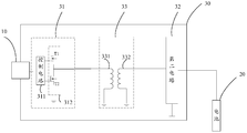
- FIG. 2 is a schematic block diagram of a charging circuit in accordance with an embodiment of the present invention.
- the charging circuit 30 of FIG. 2 is disposed between the charging interface 10 of the mobile terminal and the battery 20, and the charging circuit 30 includes: a first circuit 31 serially connected in series between the charging interface 10 and the battery 20, and magnetic coupling Element 33 and second circuit 32, wherein
- the first circuit 31 receives a first current from the charging interface 10 and converts the first current into a second current that varies in magnitude and/or direction;
- the magnetic coupling element 33 includes a first coil 331 and a second coil 332, wherein the first coil 331 is connected to the first circuit 31, and the second coil 332 is connected to the second circuit 32.
- the first coil 331 and the second coil 332 are spaced apart from each other to open a DC path of the charging circuit 30, and the magnetic coupling element 33 utilizes a second current of the magnitude and/or direction to induce electromagnetic induction.
- Means transferring energy from the first coil 331 to the second coil 332 to form a third current (ie, forming a third current in the second coil 332 and outputting the third current to the second circuit 32);
- the second circuit 32 is configured to adjust an alternating current of the first circuit 31 coupled to the second circuit 32 through the magnetic coupling element 33 to a direct current suitable for charging the battery 20.
- the DC path of the charging line is separated by the magnetic coupling element, that is, there is no DC path on the charging circuit, then, when the first circuit fails, the DC output of the charging interface is not directly output. To the second circuit and the battery, the reliability of the charging circuit is improved.
- the first circuit 31 includes a half bridge circuit 312 and a control circuit 311 for controlling the half bridge circuit.
- the half bridge circuit 311 includes a first switch tube T1 and a first The second switch tube T2, wherein the first end of the first switch tube T1 is connected to the charging port 10, and the second end of the first switch tube T2 is connected to the first end of the first coil 331.
- the control end of the first switch tube T1 is connected to the control circuit 311; the first end of the second switch tube T2 is connected to the second end of the first switch tube T1, and the second switch tube T2 The second end is connected to the ground, and the control end of the second switch T2 is connected to the control circuit 311; The second end of the first coil 331 is connected to the ground. Further, both ends of the second coil 332 may be connected to the second circuit 32 and the ground, respectively. Additionally, the second circuit 32 can be grounded.
- a switch tube (such as a MOS tube) is disposed inside the first circuit, and the switch tube is prone to breakdown.
- the switch tube breaks down, the first circuit cannot convert the direct current into an alternating current through the switch tube, resulting in The direct current input from the charging interface is directly applied to a subsequent device or battery of the charging circuit.
- a magnetic coupling element is disposed between the first circuit and the second circuit, and the magnetic coupling element disconnects the DC path of the charging circuit. open. That is to say, even if the switching tube in the first circuit is broken down or fails, the direct current input from the charging interface cannot flow to the second circuit or the battery, thereby improving the safety of the charging circuit of the mobile terminal.
- the magnetic coupling element since the magnetic coupling element has good isolation performance, the on-resistance of the switching tube in the first circuit can be made very low (there is no need to increase the on-resistance of the MOS tube to increase the withstand voltage as in the prior art) Thereby increasing the reliability of the circuit), which reduces heat generation and loss, and improves the energy transfer efficiency of the entire charging circuit.
- the first circuit includes a full bridge circuit 313 and a control circuit 311 for controlling the full bridge circuit
- the full bridge circuit 313 includes a first switch tube T1 and a second switch tube T2.
- a third switch tube T3 and a fourth switch tube T4 wherein the first end of the first switch tube T1 is connected to the charging interface 10, and the second end of the first switch tube T1 is opposite to the first coil
- the second end of the first switch tube T1 is connected to the control circuit 311; the first end of the second switch tube T2 is connected to the second end of the first switch tube T1.
- the second end of the second switch tube T2 is connected to the ground, the control end of the second switch tube T2 is connected to the control circuit 311; the first end of the third switch tube T3 is connected to the charging interface 10 Connected, the second end of the third switch tube T3 is connected to the first end of the first coil 331, the control end of the third switch tube T3 is connected to the control circuit 311; the fourth switch tube The first end of the T4 is connected to the second end of the third switch T3, and the second end of the fourth switch T4 is grounded Control terminal of the fourth switching transistor T4 is connected to the control circuit 311.
- both ends of the second coil 332 may be connected to the second circuit 32, and the second circuit may be connected to the ground.
- a switch tube (such as a MOS tube) is disposed inside the first circuit, and the switch tube is prone to breakdown.
- the first circuit cannot convert the direct current into an alternating current through the switch tube, resulting in The direct current input from the charging interface is directly applied to a subsequent device or battery of the charging circuit.
- a magnetic coupling element is disposed between the first circuit and the second circuit, and the magnetic coupling element disconnects the DC path of the charging circuit. open. That is, even in the first circuit When the switch tube is broken down or fails, the DC input from the charging interface cannot flow to the second circuit or the battery, thereby improving the safety of the charging circuit of the mobile terminal.
- the magnetic coupling element since the magnetic coupling element has good isolation performance, the on-resistance of the switching tube in the first circuit can be made very low (there is no need to increase the on-resistance of the MOS tube to increase the withstand voltage as in the prior art) Thereby increasing the reliability of the circuit), which reduces heat generation and loss, and improves the energy transfer efficiency of the entire charging circuit.
- the first circuit 31 includes a switch tube, and a control circuit for controlling the one switch tube.
- the first end of the switch tube is connected to the charging interface 10,
- a second end of a switch tube is connected to the first end of the first coil 311, and a control end of the switch tube is connected to the control circuit; a second end of the first coil is connected to the ground.
- the embodiment of the invention improves the reliability of the charging circuit on the premise that the prior art is less modified.
- the switch tube in the first circuit is a plurality of metal oxide semiconductor field effect transistor MOSFETs.
- the second circuit comprises a rectifier circuit and a filter circuit.
- FIG. 5 is a schematic block diagram of a mobile terminal according to an embodiment of the present invention.
- the mobile terminal 50 of FIG. 5 includes a charging interface 51, a battery 52, and a charging circuit 53, wherein the charging circuit 53 can be any implementation using the charging circuit 30 described above.
- the DC path of the charging line is separated by the magnetic coupling element, that is, there is no DC path on the charging circuit, then, when the first circuit fails, the DC output of the charging interface is not directly output. To the second circuit and the battery, the reliability of the charging circuit is improved.
- the charging interface 51 is a USB interface.
- the battery 20 is a lithium battery.
- the mobile terminal 50 supports a normal charging mode and a fast charging mode, wherein the charging current of the fast charging mode is greater than the charging current of the normal charging mode.
- the mobile terminal using the embodiment of the present invention can well solve the problem that the line is unreliable due to MOS breakdown during fast charging. .
- the disclosed systems, devices, and methods may be implemented in other manners.
- the device embodiments described above are merely illustrative.
- the division of the unit is only a logical function division.
- there may be another division manner for example, multiple units or components may be combined or Can be integrated into another system, or some features can be ignored or not executed.
- the mutual coupling or direct coupling or communication connection shown or discussed may be an indirect coupling or communication connection through some interface, device or unit, and may be in an electrical, mechanical or other form.
- the units described as separate components may or may not be physically separated, and the components displayed as units may or may not be physical units, that is, may be located in one place, or may be distributed to multiple network units. Some or all of the units may be selected according to actual needs to achieve the purpose of the solution of the embodiment.
- each functional unit in each embodiment of the present invention may be integrated into one processing unit, or each unit may exist physically separately, or two or more units may be integrated into one unit.
- the functions may be stored in a computer readable storage medium if implemented in the form of a software functional unit and sold or used as a standalone product.
- the technical solution of the present invention which is essential or contributes to the prior art, or a part of the technical solution, may be embodied in the form of a software product, which is stored in a storage medium, including
- the instructions are used to cause a computer device (which may be a personal computer, server, or network device, etc.) to perform all or part of the steps of the methods described in various embodiments of the present invention.
- the foregoing storage medium includes: a U disk, a mobile hard disk, a read-only memory (ROM), a random access memory (RAM), a magnetic disk, or an optical disk, and the like. .
Landscapes
- Engineering & Computer Science (AREA)
- Power Engineering (AREA)
- Charge And Discharge Circuits For Batteries Or The Like (AREA)
- Dc-Dc Converters (AREA)
Abstract
Description
Claims (10)
- 一种充电电路,其特征在于,所述充电电路设置在移动终端的充电接口和电池之间,所述充电电路包括:在所述充电接口和所述电池之间依次串联的第一电路、磁性耦合元件和第二电路,其中,所述第一电路从所述充电接口接收第一电流,并将所述第一电流转换成为大小和/或方向变化的第二电流;所述磁性耦合元件包括第一线圈和第二线圈,其中,所述第一线圈与所述第一电路相连,所述第二线圈与所述第二电路相连,所述第一线圈和所述第二线圈相互间隔,以断开所述充电电路的直流通路,所述磁性耦合元件利用所述大小和/或方向变化的第二电流,以电磁感应的方式将能量从所述第一线圈传递至所述第二线圈,形成第三电流;所述第二电路,用于将所述第三电流调整成适于为所述电池充电的第四流电,为所述电池充电。
- 如权利要求1所述的充电电路,其特征在于,所述第一电路包括半桥电路以及控制所述半桥电路的控制电路,所述半桥电路包括第一开关管和第二开关管,其中,所述第一开关管的第一端与所述充电接口相连,所述第一开关管的第二端与所述第一线圈的第一端相连,所述第一开关管的控制端与所述控制电路相连;所述第二开关管的第一端与所述第一开关管的第二端相连,所述第二开关管的第二端与地相连,所述第二开关管的控制端与所述控制电路相连;所述第一线圈的第二端与地相连。
- 如权利要求1所述的充电电路,其特征在于,所述第一电路包括全桥电路以及控制所述全桥电路的控制电路,所述全桥电路包括第一开关管、第二开关管、第三开关管和第四开关管,其中,所述第一开关管的第一端与所述充电接口相连,所述第一开关管的第二端与所述第一线圈的第二端相连,所述第一开关管的控制端与所述控制电路相连;所述第二开关管的第一端与所述第一开关管的第二端相连,所述第二开关管的第二端与地相连,所述第二开关管的控制端与所述控制电路相连;所述第三开关管的第一端与所述充电接口相连,所述第三开关管的第二 端与所述第一线圈的第一端相连,所述第三开关管的控制端与所述控制电路相连;所述第四开关管的第一端与所述第三开关管的第二端相连,所述第四开关管的第二端与地相连,所述第四开关管的控制端与所述控制电路相连。
- 如权利要求1所述的充电电路,其特征在于,所述第一电路包括一个开关管,以及控制所述一个开关管的控制电路,所述一个开关管的第一端与所述充电接口相连,所述一个开关管的第二端与所述第一线圈的第一端相连,所述一个开关管的控制端与所述控制电路相连;所述第一线圈的第二端与地相连。
- 如权利要求1-4中任一项所述的充电电路,其特征在于,所述第一电路中的开关管为金属氧化层半导体场效应晶体管MOSFET。
- 如权利要求1-5中任一项所述的充电电路,其特征在于,所述第二电路包括整流电路和滤波电路。
- 一种移动终端,其特征在于,包括:充电接口,电池,以及设置在所述充电接口和所述电池之间的如权利要求1-6中任一项所述的充电电路。
- 如权利要求7所述的移动终端,其特征在于,所述充电接口为USB接口。
- 如权利要求7或8所述的移动终端,其特征在于,所述电池为锂电池。
- 如权利要求7-9中任一项所述的移动终端,其特征在于,所述移动终端支持普通充电和快速充电两种充电模式,其中,所述快速充电模式的充电电流大于所述普通充电模式的充电电流。
Priority Applications (17)
| Application Number | Priority Date | Filing Date | Title |
|---|---|---|---|
| BR112017006269-0A BR112017006269B1 (pt) | 2015-06-01 | 2015-06-01 | Circuito de carregamento, e terminal móvel |
| CN201810141979.2A CN108390428B (zh) | 2015-06-01 | 2015-06-01 | 充电电路和移动终端 |
| CA2960419A CA2960419C (en) | 2015-06-01 | 2015-06-01 | Charging circuit and mobile terminal |
| SG11201701763YA SG11201701763YA (en) | 2015-06-01 | 2015-06-01 | Charging circuit and mobile terminal |
| KR1020177006323A KR101910303B1 (ko) | 2015-06-01 | 2015-06-01 | 충전 회로와 모바일 단말기 |
| EP15893545.2A EP3142217A4 (en) | 2015-06-01 | 2015-06-01 | Charging circuit and mobile terminal |
| MX2017004068A MX367706B (es) | 2015-06-01 | 2015-06-01 | Circuito de carga y terminal movil. |
| JP2017513190A JP2017529043A (ja) | 2015-06-01 | 2015-06-01 | 充電回路及び移動端末 |
| CN201580004523.6A CN106068593B (zh) | 2015-06-01 | 2015-06-01 | 充电电路和移动终端 |
| PCT/CN2015/080490 WO2016192007A1 (zh) | 2015-06-01 | 2015-06-01 | 充电电路和移动终端 |
| AU2015397725A AU2015397725B2 (en) | 2015-06-01 | 2015-06-01 | Charging circuit and mobile terminal |
| MYPI2017000630A MY188130A (en) | 2015-06-01 | 2015-06-01 | Charging circuit and mobile terminal |
| TW105117066A TWI646752B (zh) | 2015-06-01 | 2016-05-31 | 充電電路和移動終端 |
| US15/371,451 US10938228B2 (en) | 2015-06-01 | 2016-12-07 | Charging circuit and mobile terminal |
| PH12017500896A PH12017500896B1 (en) | 2015-06-01 | 2017-05-15 | Charging circuit and mobile terminal |
| US15/990,266 US10819121B2 (en) | 2015-06-01 | 2018-05-25 | Charging circuit and mobile terminal |
| US17/135,554 US20210119463A1 (en) | 2015-06-01 | 2020-12-28 | Charging Circuit and Mobile Terminal |
Applications Claiming Priority (1)
| Application Number | Priority Date | Filing Date | Title |
|---|---|---|---|
| PCT/CN2015/080490 WO2016192007A1 (zh) | 2015-06-01 | 2015-06-01 | 充电电路和移动终端 |
Related Child Applications (1)
| Application Number | Title | Priority Date | Filing Date |
|---|---|---|---|
| US15/371,451 Continuation US10938228B2 (en) | 2015-06-01 | 2016-12-07 | Charging circuit and mobile terminal |
Publications (1)
| Publication Number | Publication Date |
|---|---|
| WO2016192007A1 true WO2016192007A1 (zh) | 2016-12-08 |
Family
ID=57419765
Family Applications (1)
| Application Number | Title | Priority Date | Filing Date |
|---|---|---|---|
| PCT/CN2015/080490 Ceased WO2016192007A1 (zh) | 2015-06-01 | 2015-06-01 | 充电电路和移动终端 |
Country Status (14)
| Country | Link |
|---|---|
| US (3) | US10938228B2 (zh) |
| EP (1) | EP3142217A4 (zh) |
| JP (1) | JP2017529043A (zh) |
| KR (1) | KR101910303B1 (zh) |
| CN (2) | CN106068593B (zh) |
| AU (1) | AU2015397725B2 (zh) |
| BR (1) | BR112017006269B1 (zh) |
| CA (1) | CA2960419C (zh) |
| MX (1) | MX367706B (zh) |
| MY (1) | MY188130A (zh) |
| PH (1) | PH12017500896B1 (zh) |
| SG (1) | SG11201701763YA (zh) |
| TW (1) | TWI646752B (zh) |
| WO (1) | WO2016192007A1 (zh) |
Cited By (1)
| Publication number | Priority date | Publication date | Assignee | Title |
|---|---|---|---|---|
| US11894528B2 (en) | 2018-05-30 | 2024-02-06 | Milwaukee Electric Tool Corporation | Fast-charging battery pack |
Families Citing this family (8)
| Publication number | Priority date | Publication date | Assignee | Title |
|---|---|---|---|---|
| AU2015397725B2 (en) * | 2015-06-01 | 2018-10-04 | Guangdong Oppo Mobile Telecommunications Corp., Ltd. | Charging circuit and mobile terminal |
| CN108494075A (zh) * | 2015-09-22 | 2018-09-04 | 广东欧珀移动通信有限公司 | 控制充电的方法和装置以及电子设备 |
| CN209488195U (zh) | 2016-10-12 | 2019-10-11 | Oppo广东移动通信有限公司 | 移动终端 |
| CN109314396B (zh) * | 2017-04-07 | 2022-07-19 | Oppo广东移动通信有限公司 | 无线充电系统、装置、方法及待充电设备 |
| CN109787325B (zh) | 2017-04-07 | 2023-06-27 | Oppo广东移动通信有限公司 | 无线充电系统、装置、方法及待充电设备 |
| US10523042B2 (en) | 2017-05-12 | 2019-12-31 | Qualcomm Incorporated | Master-slave charging circuit with slave charger input current sensing and adaptive battery current limiting |
| EP4322367A4 (en) | 2021-09-02 | 2024-10-23 | Samsung Electronics Co., Ltd. | ELECTRONIC DEVICE HAVING A STRUCTURE FOR MINIMIZING POWER LOSS DURING CHARGING AND DISCHARGING OF A BATTERY |
| CN114567171B (zh) * | 2021-09-30 | 2022-11-29 | 惠州市乐亿通科技有限公司 | 充电装置 |
Citations (4)
| Publication number | Priority date | Publication date | Assignee | Title |
|---|---|---|---|---|
| CN201869097U (zh) * | 2010-12-10 | 2011-06-15 | 湖南南车时代电动汽车股份有限公司 | 一种带隔离具有软开关的dc/dc变换器拓扑结构 |
| CN202231473U (zh) * | 2011-09-29 | 2012-05-23 | 株洲市达能科技有限公司 | 一种高压大电流直流充电机 |
| JP2013253809A (ja) * | 2012-06-05 | 2013-12-19 | Auto Network Gijutsu Kenkyusho:Kk | 二次電池の状態検知方法、整流回路及びdc/dcコンバータ |
| CN103872728A (zh) * | 2014-03-03 | 2014-06-18 | 同济大学 | 一种多功能一体化电动汽车车载充电机 |
Family Cites Families (51)
| Publication number | Priority date | Publication date | Assignee | Title |
|---|---|---|---|---|
| US6362979B1 (en) | 2000-09-29 | 2002-03-26 | Jeff Gucyski | Switching power amplifier and uninterruptible power system comprising DC/DC converter for providing sinusoidal output |
| KR20020057469A (ko) * | 2001-01-05 | 2002-07-11 | 윤종용 | 코어 없는 초박형 프린트회로기판 변압기 및 그프린트회로기판 변압기를 이용한 무접점 배터리 충전기 |
| US6664762B2 (en) * | 2001-08-21 | 2003-12-16 | Power Designers, Llc | High voltage battery charger |
| US7135836B2 (en) * | 2003-03-28 | 2006-11-14 | Power Designers, Llc | Modular and reconfigurable rapid battery charger |
| US6934167B2 (en) * | 2003-05-01 | 2005-08-23 | Delta Electronics, Inc. | Contactless electrical energy transmission system having a primary side current feedback control and soft-switched secondary side rectifier |
| US20070210748A1 (en) * | 2006-03-09 | 2007-09-13 | Mark Unkrich | Power supply and electronic device having integrated power supply |
| JP4777155B2 (ja) * | 2006-06-15 | 2011-09-21 | パナソニック株式会社 | 電子機器、非接触型充電器及び非接触充電システム |
| KR100836634B1 (ko) * | 2006-10-24 | 2008-06-10 | 주식회사 한림포스텍 | 무선 데이타 통신과 전력 전송이 가능한 무접점 충전장치,충전용 배터리팩 및 무접점 충전장치를 이용한 휴대용단말기 |
| GB2460574B (en) | 2007-11-30 | 2013-05-08 | Agere Systems Inc | Power sharing among portable electronic devices |
| JP5118534B2 (ja) * | 2008-03-31 | 2013-01-16 | 株式会社リコー | 充電装置 |
| US8981598B2 (en) * | 2008-07-02 | 2015-03-17 | Powermat Technologies Ltd. | Energy efficient inductive power transmission system and method |
| US10355526B2 (en) | 2008-11-26 | 2019-07-16 | Auckland Uniservices Limited | Bi-directional inductive power transfer |
| CN201349185Y (zh) * | 2008-12-10 | 2009-11-18 | 胡浩 | 一种利用太阳能自调整建筑发电系统 |
| JP5198489B2 (ja) * | 2010-01-28 | 2013-05-15 | 株式会社エヌ・ティ・ティ・ドコモ | 充電回路、移動機及び充電方法 |
| CN201708573U (zh) * | 2010-04-29 | 2011-01-12 | 中山市浩成自动化设备有限公司 | 一种基于模块化控制的电动汽车充电器 |
| KR101649271B1 (ko) * | 2010-06-04 | 2016-08-30 | 삼성전자주식회사 | 스위칭 모드 전원공급장치 및 이를 이용하여 전원을 공급하는 방법 |
| JP5170165B2 (ja) | 2010-06-11 | 2013-03-27 | 株式会社村田製作所 | 絶縁型スイッチング電源装置 |
| TWM393909U (en) * | 2010-07-02 | 2010-12-01 | ming-xiang Ye | Double-sided wireless charger |
| CN201869007U (zh) | 2010-08-31 | 2011-06-15 | 安徽省临泉县智创精机有限公司 | 减速电机接头 |
| CN102412602B (zh) * | 2010-09-25 | 2014-09-03 | 深圳市茂宏电气有限公司 | 基于电池的充电供电模块 |
| CN201868097U (zh) | 2010-10-21 | 2011-06-15 | 安徽汇鑫电子有限公司 | 数字音频解码器 |
| JP2012110211A (ja) * | 2010-10-27 | 2012-06-07 | Equos Research Co Ltd | 電力伝送システム |
| TWM416006U (en) * | 2011-01-12 | 2011-11-11 | Logah Technology Corp | Wireless energy lighting device |
| WO2012101905A1 (ja) * | 2011-01-26 | 2012-08-02 | 株式会社村田製作所 | スイッチング電源装置 |
| JP5658592B2 (ja) | 2011-02-21 | 2015-01-28 | 国立大学法人埼玉大学 | 移動体用非接触給電装置 |
| KR101211234B1 (ko) * | 2011-04-11 | 2012-12-11 | 명지대학교 산학협력단 | 전기 차량용 배터리 충전 장치 |
| EP2717414B1 (en) * | 2011-05-25 | 2018-04-18 | Hitachi, Ltd. | Charging system |
| TWM417716U (en) * | 2011-07-18 | 2011-12-01 | Logah Technology Corp | Wireless charging device |
| CN105703429B (zh) * | 2011-12-28 | 2018-09-11 | 中兴通讯股份有限公司 | 一种充电方法、移动终端、充电设备及系统 |
| JP5997456B2 (ja) * | 2012-02-17 | 2016-09-28 | 学校法人慶應義塾 | 無線給電装置 |
| US9302912B2 (en) * | 2012-03-28 | 2016-04-05 | Mks Instruments, Inc. | Compact, configurable power supply for energizing ozone-producing cells |
| WO2013160960A1 (ja) * | 2012-04-27 | 2013-10-31 | 三菱電機株式会社 | Dc/dcコンバータ、車載機器および充電装置 |
| JP2014003753A (ja) | 2012-06-15 | 2014-01-09 | Sumitomo Electric Ind Ltd | 充放電システム |
| WO2014038379A1 (ja) * | 2012-09-07 | 2014-03-13 | シャープ株式会社 | ワイヤレス給電システム、およびワイヤレス受電装置 |
| US9356523B2 (en) * | 2012-12-28 | 2016-05-31 | Panasonic Intellectual Property Management Co., Ltd. | DC-to-DC converter |
| KR102019064B1 (ko) | 2013-01-29 | 2019-09-10 | 엘지이노텍 주식회사 | 무선 전력 송신 장치 및 방법 |
| US9559538B1 (en) * | 2013-03-15 | 2017-01-31 | Maxim Integrated Products, Inc. | Switch mode battery charger with improved battery charging time |
| KR101889108B1 (ko) * | 2013-06-28 | 2018-08-17 | 매그나칩 반도체 유한회사 | 대기전력소모를 감소시키는 전력변환장치 |
| CN104578439B (zh) * | 2013-10-21 | 2018-10-09 | 台达电子企业管理(上海)有限公司 | 用于无线充电线路的装置 |
| DE102013221830A1 (de) * | 2013-10-28 | 2015-04-30 | Robert Bosch Gmbh | Ladeschaltung für eine Energiespeichereinrichtung und Verfahren zum Laden einer Energiespeichereinrichtung |
| CN103580255B (zh) * | 2013-11-19 | 2016-09-14 | 惠州Tcl移动通信有限公司 | 一种快速充电终端 |
| CN103683437B (zh) * | 2013-12-31 | 2016-03-23 | 小米科技有限责任公司 | 一种充电器及终端设备 |
| US9853553B2 (en) * | 2014-03-03 | 2017-12-26 | Infineon Technologies Austria Ag | Interface circuits for USB and lighting applications |
| US10193387B2 (en) | 2014-03-07 | 2019-01-29 | Lg Electronics Inc. | Wireless power transmission apparatus and method |
| US9917518B2 (en) * | 2014-04-24 | 2018-03-13 | Semiconductor Components Industries, Llc | Method and circuit of detecting attachment and detachment between a portable device and a power converter |
| CN104065147B (zh) * | 2014-06-27 | 2017-06-06 | 宇龙计算机通信科技(深圳)有限公司 | 一种充电适配器、终端、充电控制方法 |
| US9537405B2 (en) | 2014-09-29 | 2017-01-03 | Power Integrations, Inc. | Power converter with power foldback |
| CN104393358B (zh) * | 2014-12-09 | 2017-01-04 | 山东申普交通科技有限公司 | 一种电动轻型车无损快速充电方法及充电器 |
| CN104600796B (zh) * | 2014-12-30 | 2019-09-20 | 惠州Tcl移动通信有限公司 | 快速充电的移动终端及方法、系统 |
| JP6554308B2 (ja) * | 2015-04-17 | 2019-07-31 | ローム株式会社 | バスコントローラおよび電源装置、電源アダプタ |
| AU2015397725B2 (en) * | 2015-06-01 | 2018-10-04 | Guangdong Oppo Mobile Telecommunications Corp., Ltd. | Charging circuit and mobile terminal |
-
2015
- 2015-06-01 AU AU2015397725A patent/AU2015397725B2/en not_active Ceased
- 2015-06-01 BR BR112017006269-0A patent/BR112017006269B1/pt not_active IP Right Cessation
- 2015-06-01 EP EP15893545.2A patent/EP3142217A4/en active Pending
- 2015-06-01 CA CA2960419A patent/CA2960419C/en active Active
- 2015-06-01 KR KR1020177006323A patent/KR101910303B1/ko not_active Expired - Fee Related
- 2015-06-01 MY MYPI2017000630A patent/MY188130A/en unknown
- 2015-06-01 SG SG11201701763YA patent/SG11201701763YA/en unknown
- 2015-06-01 JP JP2017513190A patent/JP2017529043A/ja active Pending
- 2015-06-01 CN CN201580004523.6A patent/CN106068593B/zh active Active
- 2015-06-01 WO PCT/CN2015/080490 patent/WO2016192007A1/zh not_active Ceased
- 2015-06-01 CN CN201810141979.2A patent/CN108390428B/zh active Active
- 2015-06-01 MX MX2017004068A patent/MX367706B/es active IP Right Grant
-
2016
- 2016-05-31 TW TW105117066A patent/TWI646752B/zh not_active IP Right Cessation
- 2016-12-07 US US15/371,451 patent/US10938228B2/en active Active
-
2017
- 2017-05-15 PH PH12017500896A patent/PH12017500896B1/en unknown
-
2018
- 2018-05-25 US US15/990,266 patent/US10819121B2/en not_active Expired - Fee Related
-
2020
- 2020-12-28 US US17/135,554 patent/US20210119463A1/en not_active Abandoned
Patent Citations (4)
| Publication number | Priority date | Publication date | Assignee | Title |
|---|---|---|---|---|
| CN201869097U (zh) * | 2010-12-10 | 2011-06-15 | 湖南南车时代电动汽车股份有限公司 | 一种带隔离具有软开关的dc/dc变换器拓扑结构 |
| CN202231473U (zh) * | 2011-09-29 | 2012-05-23 | 株洲市达能科技有限公司 | 一种高压大电流直流充电机 |
| JP2013253809A (ja) * | 2012-06-05 | 2013-12-19 | Auto Network Gijutsu Kenkyusho:Kk | 二次電池の状態検知方法、整流回路及びdc/dcコンバータ |
| CN103872728A (zh) * | 2014-03-03 | 2014-06-18 | 同济大学 | 一种多功能一体化电动汽车车载充电机 |
Non-Patent Citations (1)
| Title |
|---|
| See also references of EP3142217A4 * |
Cited By (2)
| Publication number | Priority date | Publication date | Assignee | Title |
|---|---|---|---|---|
| US11894528B2 (en) | 2018-05-30 | 2024-02-06 | Milwaukee Electric Tool Corporation | Fast-charging battery pack |
| US12166186B2 (en) | 2018-05-30 | 2024-12-10 | Milwaukee Electric Tool Corporation | Fast-charging battery pack including a charging switch |
Also Published As
| Publication number | Publication date |
|---|---|
| MX367706B (es) | 2019-09-02 |
| MY188130A (en) | 2021-11-23 |
| KR20170042644A (ko) | 2017-04-19 |
| JP2017529043A (ja) | 2017-09-28 |
| PH12017500896B1 (en) | 2021-09-15 |
| EP3142217A4 (en) | 2018-05-30 |
| CN106068593B (zh) | 2018-06-12 |
| MX2017004068A (es) | 2017-07-07 |
| AU2015397725B2 (en) | 2018-10-04 |
| US20210119463A1 (en) | 2021-04-22 |
| CA2960419A1 (en) | 2016-12-08 |
| CA2960419C (en) | 2020-01-07 |
| US20170085108A1 (en) | 2017-03-23 |
| BR112017006269B1 (pt) | 2022-08-09 |
| SG11201701763YA (en) | 2017-12-28 |
| CN108390428A (zh) | 2018-08-10 |
| AU2015397725A1 (en) | 2017-03-30 |
| US10938228B2 (en) | 2021-03-02 |
| TW201703387A (zh) | 2017-01-16 |
| CN108390428B (zh) | 2021-09-14 |
| EP3142217A1 (en) | 2017-03-15 |
| CN106068593A (zh) | 2016-11-02 |
| KR101910303B1 (ko) | 2018-10-19 |
| TWI646752B (zh) | 2019-01-01 |
| PH12017500896A1 (en) | 2017-11-06 |
| US20180278073A1 (en) | 2018-09-27 |
| BR112017006269A2 (pt) | 2017-12-12 |
| US10819121B2 (en) | 2020-10-27 |
Similar Documents
| Publication | Publication Date | Title |
|---|---|---|
| WO2016192007A1 (zh) | 充电电路和移动终端 | |
| WO2016192010A1 (zh) | 充电电路和移动终端 | |
| CN109888895B (zh) | 充电电路和移动终端 | |
| CN107800119B (zh) | 一种直流断路器仿真模型和方法 | |
| JP2017501675A (ja) | 共振整流装置、共振整流制御方法、装置、プログラム及び記録媒体 | |
| JP6153595B2 (ja) | 交流電源装置 | |
| CN107425726B (zh) | 一种反激电路 | |
| CN104184110B (zh) | 过压保护电路 | |
| CN104917405B (zh) | 用于可控硅的驱动电路以及交流模块的电路 | |
| JP2019092382A (ja) | 充電回路及び移動端末 |
Legal Events
| Date | Code | Title | Description |
|---|---|---|---|
| REEP | Request for entry into the european phase |
Ref document number: 2015893545 Country of ref document: EP |
|
| WWE | Wipo information: entry into national phase |
Ref document number: 2015893545 Country of ref document: EP |
|
| 121 | Ep: the epo has been informed by wipo that ep was designated in this application |
Ref document number: 15893545 Country of ref document: EP Kind code of ref document: A1 |
|
| ENP | Entry into the national phase |
Ref document number: 20177006323 Country of ref document: KR Kind code of ref document: A Ref document number: 2960419 Country of ref document: CA |
|
| ENP | Entry into the national phase |
Ref document number: 2017513190 Country of ref document: JP Kind code of ref document: A |
|
| WWE | Wipo information: entry into national phase |
Ref document number: MX/A/2017/004068 Country of ref document: MX |
|
| ENP | Entry into the national phase |
Ref document number: 2015397725 Country of ref document: AU Date of ref document: 20150601 Kind code of ref document: A |
|
| REG | Reference to national code |
Ref country code: BR Ref legal event code: B01A Ref document number: 112017006269 Country of ref document: BR |
|
| ENP | Entry into the national phase |
Ref document number: 2017/2673 Country of ref document: KE |
|
| WWE | Wipo information: entry into national phase |
Ref document number: 11201701763Y Country of ref document: SG |
|
| NENP | Non-entry into the national phase |
Ref country code: DE |
|
| ENP | Entry into the national phase |
Ref document number: 112017006269 Country of ref document: BR Kind code of ref document: A2 Effective date: 20170327 |