WO2016194127A1 - アンテナ装置 - Google Patents
アンテナ装置 Download PDFInfo
- Publication number
- WO2016194127A1 WO2016194127A1 PCT/JP2015/065873 JP2015065873W WO2016194127A1 WO 2016194127 A1 WO2016194127 A1 WO 2016194127A1 JP 2015065873 W JP2015065873 W JP 2015065873W WO 2016194127 A1 WO2016194127 A1 WO 2016194127A1
- Authority
- WO
- WIPO (PCT)
- Prior art keywords
- antenna
- unit
- phase difference
- angle
- altitude
- Prior art date
- Legal status (The legal status is an assumption and is not a legal conclusion. Google has not performed a legal analysis and makes no representation as to the accuracy of the status listed.)
- Ceased
Links
Images









Classifications
-
- H—ELECTRICITY
- H01—ELECTRIC ELEMENTS
- H01Q—ANTENNAS, i.e. RADIO AERIALS
- H01Q3/00—Arrangements for changing or varying the orientation or the shape of the directional pattern of the waves radiated from an antenna or antenna system
- H01Q3/02—Arrangements for changing or varying the orientation or the shape of the directional pattern of the waves radiated from an antenna or antenna system using mechanical movement of antenna or antenna system as a whole
- H01Q3/08—Arrangements for changing or varying the orientation or the shape of the directional pattern of the waves radiated from an antenna or antenna system using mechanical movement of antenna or antenna system as a whole for varying two co-ordinates of the orientation
-
- H—ELECTRICITY
- H04—ELECTRIC COMMUNICATION TECHNIQUE
- H04B—TRANSMISSION
- H04B7/00—Radio transmission systems, i.e. using radiation field
- H04B7/14—Relay systems
- H04B7/15—Active relay systems
- H04B7/185—Space-based or airborne stations; Stations for satellite systems
- H04B7/18502—Airborne stations
- H04B7/18506—Communications with or from aircraft, i.e. aeronautical mobile service
- H04B7/18508—Communications with or from aircraft, i.e. aeronautical mobile service with satellite system used as relay, i.e. aeronautical mobile satellite service
-
- H—ELECTRICITY
- H01—ELECTRIC ELEMENTS
- H01Q—ANTENNAS, i.e. RADIO AERIALS
- H01Q1/00—Details of, or arrangements associated with, antennas
- H01Q1/27—Adaptation for use in or on movable bodies
- H01Q1/28—Adaptation for use in or on aircraft, missiles, satellites, or balloons
-
- H—ELECTRICITY
- H01—ELECTRIC ELEMENTS
- H01Q—ANTENNAS, i.e. RADIO AERIALS
- H01Q21/00—Antenna arrays or systems
- H01Q21/06—Arrays of individually energised antenna units similarly polarised and spaced apart
-
- H—ELECTRICITY
- H04—ELECTRIC COMMUNICATION TECHNIQUE
- H04B—TRANSMISSION
- H04B1/00—Details of transmission systems, not covered by a single one of groups H04B3/00 - H04B13/00; Details of transmission systems not characterised by the medium used for transmission
- H04B1/06—Receivers
Definitions
- the present invention relates to an antenna device for satellite communication mounted on a mobile object such as an aircraft.
- An antenna device for satellite communication mounted on an aircraft is attached to the upper part of the aircraft body, which increases air resistance.
- An antenna mounted on an aircraft is required to reduce drag (referred to as drag) due to air resistance (referred to as low drag).
- the antenna elements are mounted on a base that rotates one azimuth angle. Therefore, when the diameter of the base is reduced, the distance between the antenna elements is reduced. When the interval is narrow, when the antenna is directed at a low elevation angle, interference and blocking between the antenna elements increase, and the antenna gain decreases. When the distance between the antenna elements is increased, interference and blocking between the antenna elements at a low elevation angle are reduced, but the base becomes longer in the arrangement direction of the antenna elements. As a result, the diameter of the base that rotates the azimuth is increased. As the diameter of the base increases, the width of the antenna device as viewed from the direction of travel of the mounted aircraft increases, and the cross-sectional area toward the nose increases even if the height of the antenna device is low. That is, there is a problem that there is a trade-off relationship between a decrease in antenna gain due to interference or blocking between antenna elements and a reduction in the cross-sectional area in the nose direction.
- the present invention has been made in order to solve the above-described problems.
- the antenna In an antenna apparatus in which a cross-sectional area in the nose direction is reduced by forming a single antenna by a plurality of antenna elements, the antenna has a low elevation angle. It is an object of the present invention to obtain an antenna device that can maintain the antenna gain even when the antenna is directed.
- An antenna device includes an antenna that receives a radio wave from a satellite and generates a reception signal, and an antenna driving unit that changes a directivity direction that is a direction of the antenna, and is arranged in a row. Having an antenna unit. Furthermore, a direction command value generation unit that generates a direction command value that is a command value given to the antenna drive unit so that the direction in which the satellite exists and the pointing direction match, and the phase of the reception signal generated by the plurality of antennas A phase difference calculation unit that calculates a phase difference that is a difference between the two and a signal synthesis device that synthesizes a plurality of received signals based on the phase difference.
- the antenna gain can be maintained even when the antenna is directed at a low elevation angle, and the cross-sectional area of the antenna device viewed from the front in the traveling direction of the moving body can be reduced.
- FIG. 1 It is a side view in the state where the height of the antenna device in which two antennas as a second comparative example rotate around the same azimuth axis is maximized. It is a figure explaining the state in which the shielding of the antenna has generate
- FIG. It is a figure explaining the relationship between the antenna azimuth at the altitude angle which antenna shielding generate
- FIG. It is a functional block diagram of the antenna apparatus which concerns on Embodiment 2 of this invention.
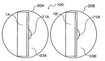
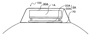
- the antenna units 30 ⁇ / b> A and 30 ⁇ / b> B are installed on the antenna installation surface at the top of the nose of the aircraft 70.
- the direction perpendicular to the antenna installation surface is called the aircraft vertical direction.
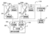
- the nose-side antenna unit 30A has an antenna 1A that receives a radio wave from a satellite and generates a reception signal, an amplifier 2A that amplifies the reception signal output by the antenna 1A, and a direction in which the antenna 1A faces.
- the aft-side antenna unit 30B includes an antenna 1B, an amplifier 2B, an antenna driving unit 3B, and an airframe fixing unit 71B.
- the antenna 1A and the antenna 1B have the same configuration, and the term “antenna 1” is used when both the antennas 1A and 1B are concerned.
- the amplifier 2 and the like are also expressed in the same manner.
- the antenna device 100 includes a phase difference calculation unit 4 that calculates a phase difference between reception signals generated by the two antennas 1A and 1B, and a direction that generates a direction command value of the directivity direction of the antenna 1 given to the antenna drive unit 3.
- the command value generation unit 5 and a signal synthesis device 40 that synthesizes the received signals that are output and amplified by the two antennas 1A and 1B based on the phase difference calculated by the phase difference calculation unit 4 are further provided.
- the signal output from the signal synthesizer 40 is demodulated by a demodulator 50 (not shown).
- the signal synthesizer 40 includes two phase shifters 6A and 6B that adjust so that the phases of the two input signals are synchronized, and a synthesizer 7 that synthesizes the signals whose phases are synchronized by the phase shifters 6A and 6B. And have.
- the phase shifter 6A adjusts the phase of the signal received by the antenna 1A.
- the phase shifter 6B adjusts the phase of the signal received by the antenna 1B. Since the received signals of the antennas 1A and 1B are adjusted by the phase shifters 6A and 6B so that the phases match each other, the synthesizer 7 synthesizes the received signal and doubles the received signal strength.
- an antenna gain equivalent to that obtained when a signal from a satellite is received by one antenna having an opening area twice that of the antenna 1A and the antenna 1B can be obtained. Since the purpose is to reduce the phase difference to zero, only the phase on one side may be adjusted so that one of the phase shifters 6A and 6B is not provided. A necessary number of phase shifters may be provided at necessary locations so that the phases of a plurality of received signals can be matched based on the phase difference.
- the antenna 1 is desirably a planar antenna in order to make full use of the effects of the present invention.
- the planar antenna has no physical restriction on the shape of the aperture surface unlike the parabolic antenna, and the aperture surface shape can be freely determined.
- a planar antenna even if the antenna has the same aperture area and antenna gain, it can be a horizontally long rectangular planar antenna. By making it horizontally long, the height of the antenna 1 can be kept low even when a low elevation angle is directed.
- an antenna device with a reduced height can be realized as shown in FIGS.
- the amplifier 2 amplifies the received signal input from the antenna 1 and outputs the amplified signal to the subsequent phase shifter 6.
- the amplifier 2 is installed on the back surface of the antenna 1 so that the signal-to-noise ratio of the received signal does not deteriorate as much as possible. Amplifiers may be installed at other positions.
- the width of the antenna device is increased by the supporting member.
- the altitude axis 31 is arranged behind the antenna 1. It is good also as a structure which supports a planar antenna from the side.
- the altitude angle changing unit 32 and the azimuth changing unit 33 have a motor that generates a driving force to be rotated and a driving force transmission mechanism that is rotated by the driving force generated by the motor, although not shown.
- the antenna driving unit 3 includes a drive control unit 34 (not shown) that controls the motor so that the azimuth angle and altitude angle of the antenna, that is, the antenna directing direction matches the direction command value.
- the direction command value may be determined by a hybrid method combining an open method and a closed loop method.
- the direction command value for the drive control unit 34 is given by any of these methods, and the drive control unit 34 drives the antenna so that the antenna is directed in the direction in which the satellite exists within an allowable deviation from the direction command value.
- the unit 3 is driven.
- the phase difference calculation unit 4 calculates a phase difference between the reception signals necessary for optimally combining the reception signals output from the antennas 1 ⁇ / b> A and 1 ⁇ / b> B, and outputs the phase difference to the signal synthesis device 40.
- a method of calculating the phase difference will be described with reference to FIG.
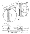
- FIG. 6 is a diagram for explaining a path length difference between radio waves received by a plurality of antennas included in the antenna device according to the first embodiment.
- the azimuth angle ⁇ is an angle between the azimuth direction component obtained by projecting the antenna directivity direction 82 perpendicularly to the antenna installation surface and the nose direction 81.
- the altitude angle ⁇ is an angle between the aircraft vertical direction 83 and the antenna directing direction 82.
- the inter-unit distance which is the distance between the centers of the azimuth axes of the antenna units 30A and 30B, is represented by a variable L.
- a directivity direction distance that is a distance obtained by projecting the inter-unit distance L into the directivity direction 82 of the antenna is represented by a variable D.
- D L * cos ⁇ (1)
- the path length difference E of the signals from the satellites received by the antennas 1A and 1B has the following relationship with the pointing direction distance D.
- E D * sin ⁇ (2)
- the following formula is obtained by combining the formula (1) and the formula (2). That is, the path length difference E is determined from the azimuth angle ⁇ and the altitude angle ⁇ .
- E L * cos ⁇ * sin ⁇ (3)
- the phase difference ⁇ of the signals from the satellites received by the antennas 1A and 1B is obtained by dividing the path length difference E by the signal wavelength ⁇ .
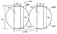
- FIG. 7 is a plan view of the antenna device according to Embodiment 1 in a state where the antenna is oriented in a direction perpendicular to the installation surface.
- FIG. 8 is a side view of the antenna device according to Embodiment 1 in a state where the height is maximum.
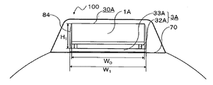
- FIG. 9 is a front view of the antenna device according to Embodiment 1 in a state where the height is maximum. 7 to 9 are diagrams in the case where the antenna 1 faces the nose direction. As can be seen from the front view of FIG. 9, it is one of the features of the present invention that even if a plurality of antenna units are arranged in the traveling direction of the airframe, the cross-sectional area in the nose direction is that of one antenna unit. is there.
- the width of the antenna 1 is expressed by a variable W 0 and the height is expressed by a variable H 0 .
- the distance between the center of the altitude axis that changes the altitude angle ⁇ of the antenna 1 and the aperture plane that receives the radio waves of the antenna 1 (referred to as altitude axis distance) is expressed by a variable d 0 .
- the altitude axis 31 is provided at a position where a straight line including the center of the altitude axis 31 and perpendicular to the aperture plane of the antenna 1 and the aperture plane bisects the aperture plane in the height direction.
- the height from the antenna installation surface at the center of the altitude axis 31 is half of the height H 0 of the antenna 1.
- the antenna space 84 is a disk-shaped space. It represents the diameter of the antenna space 84 in variable W 1, expressing the height variable H 1.
- W 1 the diameter of the antenna space 84 in variable W 1
- H 1 the height variable H 1.
- the diameter W 1 of the antenna space 84 can be calculated by the following formula.
- the diameter of the azimuth angle changing unit 33 is expressed as the same as the diameter of the antenna space 84.
- W 1 ⁇ (W 0 2 + H 0 2 + d 0 2 ) (4)
- the inter-unit distance L needs to allow each antenna unit 30 to rotate without any problem, and needs to satisfy the following. L ⁇ W 1 (5)
- the height H1 of the antenna space can be calculated by the following formula.
- H 1 H 0/2 + ⁇ ((H 0/2) 2 + d 0 2) (6)
- S 1 S 1 can be calculated by the following expression.
- the antenna device has a feature that the cross-sectional area S 1 in the nose direction does not depend on the distance L between the antenna units 30.
- the first comparative example is a single antenna having the same opening area.
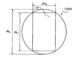
- FIG. 10 is a plan view in a state where one antenna having the same opening area as the first comparative example faces a direction perpendicular to the installation surface.
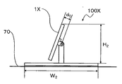
- FIG. 11 is a side view in a state where the height of one antenna having the same opening area as the first comparative example is maximized.
- the antenna device 100X as the first comparative example has one antenna 1X.
- the width of the antenna 1X is the same W 0 as in the first embodiment, the height is 2H 0 which is twice the height, and the altitude axial distance is d 0 .
- the diameter of the antenna space in the first comparative example is expressed by a variable W 2
- the height of the antenna space is expressed by a variable H 2
- the cross-sectional area in the nose direction is expressed by a variable S 2 .
- the antenna space diameter W 2 , height H 2 and nose cross-sectional area S 2 in the first comparative example can be calculated by the following equations.
- the antenna device 100 of the present invention has the following.
- the calculation for the antenna device 100X of the first comparative example is as follows.
- the reduction ratio ⁇ 2 of the cross-sectional area in the nose direction relative to the first comparative example is as follows.
- the cross-sectional area in the nose direction can be reduced to about 48% and less than half of the first comparative example.
- FIG. 12 is a plan view of the antenna device in which the two antennas as the second comparative example rotate around the same azimuth axis in a state in which the antenna faces a direction perpendicular to the installation surface.
- the antenna device 100Y of the second comparative example includes a front antenna 1YA and a rear antenna 1YB.
- FIG. 12 shows a state where the antennas 1YA and 1YB are directed in the direction in which the width of the antenna viewed from the nose direction is maximized.
- FIG. 13 is a side view of the antenna device in which the two antennas as the second comparative example rotate around the same azimuth axis in the maximum height.
- the antennas 1YA and 1YB are the same as the antennas 1A and 1B.
- an interval L exists between the two antennas 1YA and 1YB.
- the reduction ratio ⁇ 3 of the cross-sectional area in the nose direction for the second comparative example is as follows.
- the cross-sectional area in the nose direction can be reduced to about 62% with respect to the second comparative example.
- the inter-unit distance L is increased so as to reduce the shielding of the antenna at a low elevation angle, the reduction rate of the nose cross-sectional area of the present invention when compared with the second comparative example increases.
- the cross-sectional area in the nose direction can be reduced as compared with the conventional antenna device having the same opening area.
- the cross-sectional area for the nose can be reduced also when the antenna is divided into three or more.
- FIG. 14 is a diagram for explaining a state where the antenna is shielded in the antenna device according to the first embodiment.
- FIG. 14 as shown in the upper plan view, there is a shielding portion 85 where shielding occurs.
- the shielding portion 85 is hatched.
- the height of the portion where the front and rear antennas overlap when viewed from the antenna directivity direction is referred to as the overlap height.
- the width of the portion where the antennas overlap is called the overlapping width.
- Duplicate height represented by the variable G H1 it represents the overlapping width variable G W1, representing the area of the shielding part variable G S1.
- the minimum altitude angle at which shielding occurs in the second comparative example is called the shielding start altitude angle and is represented by a variable ⁇ s0.
- the shielding start altitude angle ⁇ s0 is also the minimum altitude angle at which an overlapping portion occurs in the height direction when the azimuth angle ⁇ is 0 degrees in the antenna device 100 of the present invention.
- the shielding start azimuth angle ⁇ S that is the azimuth angle ⁇ at which the overlapping portion occurs in the height direction at the altitude angle ⁇ where the overlapping portion occurs in the height direction can be calculated by the following equation.
- ⁇ S 0 for ⁇ ⁇ ⁇ s0 (16)
- ⁇ S cos ⁇ 1 (H 0 / (L * cos ⁇ )) for ⁇ ⁇ s0 (17)
- the angle between the azimuth direction component of the directivity direction 82 (the direction in which the antenna directivity direction 82 is projected on the antenna installation surface) and the nose direction 81 is the azimuth angle ⁇ . It is.
- the length of the line segment connecting the upper left corners of the antennas 1A and 1B is the unit distance L, and this line segment is parallel to the nose direction 81.
- the intersection of the antenna 1B with a straight line passing through the upper end in the drawing of the antenna 1A and parallel to the directivity direction 82 and the antenna 1B is located at a position at a lower distance in the drawing by L * sin ⁇ from the upper end in the drawing of the antenna 1B.
- the overlap width Gw1 can be calculated by the following formula.
- G W1 max (0, W 0 -L * sin ⁇ ) (18)
- the shielding end azimuth angle ⁇ F which is the maximum azimuth angle ⁇ at which the front and rear antennas overlap in the width direction can be calculated by the following equation.
- the shielding end azimuth angle ⁇ F decreases as the unit distance L increases.
- ⁇ F sin ⁇ 1 (W 0 / L) (19)
- the azimuth angle ⁇ is large, that is, when the angle difference between the aircraft traveling direction and the azimuth angle component in the pointing direction is large, shielding is not generated regardless of the altitude angle ⁇ . This is a feature of the present invention not found in the technology.
- G S1 G H1 *
- G W1 Max (0, H 0 -L * cos ⁇ * cos ⁇ ) * max (0, W 0 -L * sin ⁇ ) (20)
- the expression (20) for calculating the area G S1 shielding portion of the first embodiment also includes azimuth alpha. That is, when the azimuth angle ⁇ is changed, a change in the area G S1 shielding portion.
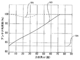
- the ratio of the area G S1 of the shielded portion of the antenna to the aperture area of the antenna is called a shielding rate, and is expressed by a variable K 1 ( ⁇ , ⁇ ).
- the antenna utilization factor of the whole antenna in consideration of shielding is expressed by a variable M 1 ( ⁇ , ⁇ ).
- the shielding factor K 1 ( ⁇ , ⁇ ) and the antenna utilization factor M 1 ( ⁇ , ⁇ ) can be calculated by the following equations.
- the area G S1 of the shielding portion is also expressed as G S1 ( ⁇ , ⁇ ) to indicate that it is a function of the azimuth angle ⁇ and the altitude angle ⁇ .
- K 1 ( ⁇ , ⁇ ) G S1 ( ⁇ , ⁇ ) / (H 0 * W 0 ) (22)
- M 1 ( ⁇ , ⁇ ) 1.0-0.5 * K 1 ( ⁇ , ⁇ ) (23)
Landscapes
- Engineering & Computer Science (AREA)
- Physics & Mathematics (AREA)
- Astronomy & Astrophysics (AREA)
- Aviation & Aerospace Engineering (AREA)
- General Physics & Mathematics (AREA)
- Computer Networks & Wireless Communication (AREA)
- Signal Processing (AREA)
- Remote Sensing (AREA)
- Variable-Direction Aerials And Aerial Arrays (AREA)
- Details Of Aerials (AREA)
Abstract
Description
図1は、この発明の実施の形態1に係るアンテナ装置の側面図である。図2は、実施の形態1に係るアンテナ装置の平面図である。図3は、実施の形態1に係るアンテナ装置の正面図である。図4は、実施の形態1に係るアンテナ装置の背面図である。図5は、実施の形態1に係るアンテナ装置の機能ブロック図である。この実施の形態1に係るアンテナ装置100では、2個のアンテナユニット30A、30Bが航空機70の機首上部に、機体と平行に一列に決められた間隔で配置されている。アンテナユニットは、3個以上を1列に決められた間隔で配列してもよい。なお、機体の方向と機体の進行方向とは、同じ方向である。機体の方向を機首方向とも呼ぶ。
アンテナ1A、1Bの受信信号が位相器6A、6Bにより位相が一致するように調整されているため、合成器7では最大合成され受信信号強度が2倍になる。こうして、アンテナ1Aおよびアンテナ1Bの2倍の開口面積を有する1個のアンテナで衛星からの信号を受信した場合と同等のアンテナ利得を得ることができる。
なお、位相差をゼロにすることが目的なので、一方の側の位相だけを調整することにして、位相器6A、6Bのどちらかを備えないようにしてもよい。位相差に基づき複数の受信信号の位相を合わせることができるように、必要な数の位相器を必要な箇所に設ければよい。
D=L*cosα (1)
E=D*sinβ (2)
式(1)と式(2)とを組み合わせて、以下の式が得られる。つまり、経路長差Eは、方位角αと高度角βとから決まる。
E=L*cosα*sinβ (3)
アンテナ1A、1Bが受信する衛星からの信号の位相差δは、経路長差Eを信号の波長λで割ることにより得られる。
W1=√(W0 2+H0 2+d0 2) (4)
ここで、ユニット間距離Lは、それぞれのアンテナユニット30が支障なく回転できるようにする必要があり、以下を満足する必要がある。
L≧W1 (5)
H1=H0/2+√((H0/2)2+d0 2) (6)
機首方向から見た場合のアンテナ空間の断面積である機首向断面積を変数S1で表現すると、S1は以下の式で計算できる。厳密にはアンテナ空間の断面形状は角が丸いが、簡単のため長方形として計算する。
S1=W1*H1
=√(W0 2+H0 2+d0 2)*(H0/2+√((H0/2)2+d0 2)) (7)
式(7)から分かるように、この発明に係るアンテナ装置では、機首向断面積S1がアンテナユニット30間の距離Lによらないという特長を持つ。
第1の比較例でのアンテナ空間の直径W2、高さH2および機首向断面積S2は、以下の式で計算できる。
W2=√(W0 2+4H0 2+d0 2) (8)
H2=H0+√(H0 2+d0 2) (9)
S2=W2*H2
=√(W0 2+4H0 2+d0 2)*(H0+√(H0 2+d0 2)) (10)
W1=√(1.002+0.302+0.102)=1.049m
H1=0.30/2+√((0.30/2)2+0.102)=0.330m
S1=W1*H1=1.049*0.330=0.346m2
第1の比較例のアンテナ装置100Xに対して計算すると、以下のようになる。
W2=√(1.002+4*0.302+0.102)=1.170m
H2=0.30+√(0.302+0.102)=0.616m
S2=W2*H2=1.170*0.616=0.721m2
第1の比較例に対する機首向断面積の減少率γ2は、以下のようになる。第1の比較例に対して約48%と半分未満に、機首向断面積を小さくできる。
γ2=S1/S2=0.346/0.721=0.480
なお、高度軸距離d0がより小さくなれば、減少率γ2はより小さくなる。d0=0mであれば、γ2=0.448になる。
第2の比較例でのアンテナ空間の直径W3、高さH3および機首向断面積S3は、以下の式で計算できる。
W3=√(W0 2+(L+√(H0 2+d0 2))2) (11)
H3=H1=H0/2+√((H0/2)2+d0 2) (12)
S3=W3*H3
=√(W0 2+(L+√(H0 2+d0 2))2)
*(H0/2+√((H0/2)2+d0 2)) (13)
L=W1の場合での第2の比較例について計算した結果は、以下のようになる。
W3=√(1.002+(1.049+√(0.302+0.102))=1.692m
H3=H1=0.330m
S3=W3*H3=1.692*0.330=0.558m2
γ3=S1/S3=0.346/0.6558=0.620
L=W1の場合の第2の比較例は、低仰角での遮蔽がこの発明と同程度であると想定する場合である。この発明の方が、機首向断面積を第2の比較例の半分近くまで小さくできることが分かる。
GH1=max(0, H0-L*cosα*cosβ) (14)
βs0=cos-1(H0/L) (15)
高さ方向で重複する部分が発生する高度角βにおいて、高さ方向で重複する部分が発生する方位角αである遮蔽開始方位角αSは、以下の式で計算できる。
αS=0 for β≧βs0 (16)
αS=cos-1(H0/(L*cosβ)) for β<βs0 (17)
GW1=max(0, W0-L*sinα) (18)
αF=sin-1(W0/L) (19)
式(19)に示すように、方位角αが大きい、すなわち航空機の進行方向と指向方向の方位角成分との角度差が大きい場合に、高度角βによらず遮蔽が発生しないことが、従来技術にはなかったこの発明の特長である。
GS1=GH1*GW1
=max(0, H0-L*cosα*cosβ)
*max(0, W0-L*sinα) (20)
βsm=cos-1(H0/√(L2-W0 2)) (21)
K1(α,β)=GS1(α,β)/(H0*W0) (22)
M1(α,β)=1.0-0.5*K1(α,β) (23)
GH2=max(0, H0-L*cosβ) (24)
第2の比較例では、方位軸の回りに回転しても常に前方のアンテナの指向方向の真後ろに後方のアンテナが存在する。そのため、重複幅GW2は、以下の式で計算できる。
GW2=W0 (25)
したがって、遮蔽部分の面積変数GS2は、以下の式で計算できる。
GS2=GH2*GW2
=max(0, H0-L*cosβ)*W0 (26)
K2(β)=GS2(β)/(H0*W0) (27)
M2(β)=1.0-0.5*K2(β) (28)
遮蔽部分の平均面積GSAは、下に示す式で計算できる。なお、方位角αに関しては、前後のアンテナの位置関係は、正負対称かつ90度(=π/2[rad])に対しても対称なので、αの積分範囲は0からπ/2[rad]とする。
GSA=(1/π)∫GS1dα (29)
GSA=(2/π)*H0*W0
*(αF-αS-(L/W0)*(cosαS-cosαF)
-(W0/H0)*(cosβ/2)
+(L*cosβ/H0)*sinαS
-(L2*cosβ/(2H0*W0))*sin2αS ) (30)
方位角αが0度で高さ方向に重複する部分が発生する高度角β(≧βs0)での遮蔽部分の平均面積GSAは、以下の式で計算できる。
GSA=(2/π)*H0*W0
*(αF-(L/W0)*(1-cosαF)-(W0/H0)*(cosβ/2)) (31)
KA1(β)=GSA(β)/(H0*W0) (32)
MA1(β)=1.0-0.5*KA1(β) (33)
このように、この発明では、前後のアンテナを別の方位軸で回転させることにより、方位角が大きくなると、前後のアンテナの重なりが発生しなくなる。そのため、第2の比較例よりも、この発明の方が、アンテナが低仰角を指向する場合のアンテナの遮蔽による有効な開口面の面積の減少が小さくなる。すなわち、アンテナの利用率すなわちアンテナ利得が低下する場合でも、アンテナ利得を許容できる下限以上にある状態を維持できる。
以上のことは、他の実施の形態にもあてはまる。
実施の形態2は、アンテナが受信した電波から生成したアナログ信号をデジタル信号に変換してから合成する場合である。図18は、この発明の実施の形態2の機能ブロック図である。実施の形態1の場合の図5と異なる点だけを説明する。
30A、30B アンテナユニット
70 機体
71A、71B 機体固定部(移動体固定部)
1A、1B、1X、1YA、1YB アンテナ
2A、2B 増幅器
3A、3B アンテナ駆動部
31A、31B 高度軸
32A、32B 高度角変更部
33A、33B 方位角変更部
34 駆動制御部
4 位相差算出部
5 方向指令値生成部
40 信号合成装置
6A、6B 位相器
7 合成器
50 復調装置
81 機首方向
82 指向方向
83 機体面垂直方向
84 アンテナ空間
85 遮蔽部分
91、92、93、94、95、96,97、98、99 グラフ
8A、8B 周波数変換器
9A、9B A/D変換器9A
15 復調演算部
Claims (7)
- 衛星からの電波を受信して受信信号を生成するアンテナと、前記アンテナが向く方向である指向方向を変更するアンテナ駆動部とを有し、一列に配置された複数のアンテナユニットと、
前記衛星が存在する方向と前記指向方向とが一致するように、前記アンテナ駆動部に与えられる指令値である方向指令値を生成する方向指令値生成部と、
複数の前記アンテナが生成する前記受信信号の位相の差である位相差を算出する位相差算出部と、
前記位相差に基づき複数の前記受信信号を合成する信号合成装置とを備えたアンテナ装置。 - 前記アンテナユニットは、前記アンテナ駆動部を移動体に固定する移動体固定部を有し、
前記方向指令値生成部は、前記移動体の位置および姿勢と前記衛星の位置に基づき前記方向指令値を生成することを特徴とする請求項1に記載のアンテナ装置。 - 前記アンテナ駆動部は、前記アンテナの長手方向に平行な高度軸の回りに前記アンテナを回転可能に支持する高度角変更部と、前記高度軸に垂直な方位軸の回りに前記高度角変更部を前記移動体固定部に対して回転可能に支持する方位角変更部とを有することを特徴とする請求項2に記載のアンテナ装置。
- 複数の前記アンテナユニットは、前記移動体の進行方向に平行な一本の直線上にそれぞれの前記方位軸が存在するように配置されることを特徴とする請求項3に記載のアンテナ装置。
- 複数の前記アンテナユニットが有する前記アンテナが同じ大きさであることを特徴とする請求項1から請求項4までの何れか1項に記載のアンテナ装置。
- 前記信号合成装置は、前記位相差に基づき複数の前記受信信号の位相を合わせることができるように設けられた位相器と、前記位相器が出力する位相が調整された前記受信信号を合成する合成器とを有することを特徴とする請求項1から請求項5までの何れか1項に記載のアンテナ装置。
- 前記信号合成装置は、前記受信信号を決められたサンプリング周期で決められたビット数のデジタル信号であるデジタル受信信号に変換する前記アンテナごとに設けられた複数の連続離散変換器と、複数の前記デジタル受信信号を前記位相差に基づいて合成する復調演算部とを有することを特徴とする請求項1から請求項5までの何れか1項に記載のアンテナ装置。
Priority Applications (4)
| Application Number | Priority Date | Filing Date | Title |
|---|---|---|---|
| EP15894162.5A EP3306749A4 (en) | 2015-06-02 | 2015-06-02 | Antenna device |
| US15/579,021 US20180145407A1 (en) | 2015-06-02 | 2015-06-02 | Antenna apparatus |
| PCT/JP2015/065873 WO2016194127A1 (ja) | 2015-06-02 | 2015-06-02 | アンテナ装置 |
| JP2016570357A JPWO2016194127A1 (ja) | 2015-06-02 | 2015-06-02 | アンテナ装置 |
Applications Claiming Priority (1)
| Application Number | Priority Date | Filing Date | Title |
|---|---|---|---|
| PCT/JP2015/065873 WO2016194127A1 (ja) | 2015-06-02 | 2015-06-02 | アンテナ装置 |
Publications (1)
| Publication Number | Publication Date |
|---|---|
| WO2016194127A1 true WO2016194127A1 (ja) | 2016-12-08 |
Family
ID=57440385
Family Applications (1)
| Application Number | Title | Priority Date | Filing Date |
|---|---|---|---|
| PCT/JP2015/065873 Ceased WO2016194127A1 (ja) | 2015-06-02 | 2015-06-02 | アンテナ装置 |
Country Status (4)
| Country | Link |
|---|---|
| US (1) | US20180145407A1 (ja) |
| EP (1) | EP3306749A4 (ja) |
| JP (1) | JPWO2016194127A1 (ja) |
| WO (1) | WO2016194127A1 (ja) |
Families Citing this family (5)
| Publication number | Priority date | Publication date | Assignee | Title |
|---|---|---|---|---|
| US10419245B2 (en) * | 2016-11-29 | 2019-09-17 | Motorola Mobility Llc | Method and apparatus for determining parameters and conditions for line of sight MIMO communication |
| US10250306B2 (en) | 2016-11-29 | 2019-04-02 | Motorola Mobility Llc | Method and apparatus for determining parameters and conditions for line of sight MIMO communication |
| US10320471B1 (en) * | 2018-06-26 | 2019-06-11 | Panasonic Avionics Corporation | Dynamic effective isotropic radiated power spectral density control |
| US12487310B2 (en) * | 2021-04-06 | 2025-12-02 | Elta Systems Ltd. | Direction finder antenna system |
| US12082001B2 (en) | 2022-11-21 | 2024-09-03 | Peltbeam Inc. | Antenna device, FWA communication system with antenna device, and method for FWA communication |
Citations (4)
| Publication number | Priority date | Publication date | Assignee | Title |
|---|---|---|---|---|
| JPH08250921A (ja) * | 1995-03-10 | 1996-09-27 | Alpine Electron Inc | 車載用衛星放送受信機 |
| JP2005510104A (ja) * | 2001-11-09 | 2005-04-14 | イーエムエス テクノロジイーズ インコーポレーテッド | 移動車両用のアンテナ・アレイ |
| JP3767372B2 (ja) * | 2000-11-22 | 2006-04-19 | 三菱電機株式会社 | 衛星追尾用アンテナ制御装置 |
| JP2014187489A (ja) * | 2013-03-22 | 2014-10-02 | Furuno Electric Co Ltd | ダイバーシチ受信装置、ダイバーシチ受信方法、及びダイバーシチ受信プログラム |
Family Cites Families (6)
| Publication number | Priority date | Publication date | Assignee | Title |
|---|---|---|---|---|
| JPS6381509U (ja) * | 1986-11-15 | 1988-05-28 | ||
| JP3032310B2 (ja) * | 1991-02-28 | 2000-04-17 | 株式会社豊田中央研究所 | 追尾アンテナ装置 |
| JP3306758B2 (ja) * | 1992-11-30 | 2002-07-24 | 日本放送協会 | 衛星放送移動受信装置 |
| CA2110205C (en) * | 1992-11-30 | 1999-11-23 | Noboru Toyama | Mobile receiver for satellite broadcast |
| US7911400B2 (en) * | 2004-01-07 | 2011-03-22 | Raysat Antenna Systems, L.L.C. | Applications for low profile two-way satellite antenna system |
| US7903038B2 (en) * | 2006-12-08 | 2011-03-08 | Lockheed Martin Corporation | Mobile radar array |
-
2015
- 2015-06-02 EP EP15894162.5A patent/EP3306749A4/en not_active Withdrawn
- 2015-06-02 WO PCT/JP2015/065873 patent/WO2016194127A1/ja not_active Ceased
- 2015-06-02 JP JP2016570357A patent/JPWO2016194127A1/ja active Pending
- 2015-06-02 US US15/579,021 patent/US20180145407A1/en not_active Abandoned
Patent Citations (4)
| Publication number | Priority date | Publication date | Assignee | Title |
|---|---|---|---|---|
| JPH08250921A (ja) * | 1995-03-10 | 1996-09-27 | Alpine Electron Inc | 車載用衛星放送受信機 |
| JP3767372B2 (ja) * | 2000-11-22 | 2006-04-19 | 三菱電機株式会社 | 衛星追尾用アンテナ制御装置 |
| JP2005510104A (ja) * | 2001-11-09 | 2005-04-14 | イーエムエス テクノロジイーズ インコーポレーテッド | 移動車両用のアンテナ・アレイ |
| JP2014187489A (ja) * | 2013-03-22 | 2014-10-02 | Furuno Electric Co Ltd | ダイバーシチ受信装置、ダイバーシチ受信方法、及びダイバーシチ受信プログラム |
Non-Patent Citations (1)
| Title |
|---|
| See also references of EP3306749A4 * |
Also Published As
| Publication number | Publication date |
|---|---|
| US20180145407A1 (en) | 2018-05-24 |
| EP3306749A1 (en) | 2018-04-11 |
| JPWO2016194127A1 (ja) | 2017-06-22 |
| EP3306749A4 (en) | 2018-12-26 |
Similar Documents
| Publication | Publication Date | Title |
|---|---|---|
| JPWO2016194127A1 (ja) | アンテナ装置 | |
| US11817636B2 (en) | System and method for a digitally beamformed phased array feed | |
| CN115639849B (zh) | 一种机电复合的目标过顶跟踪方法及装置 | |
| CN120009916A (zh) | 一种用于低轨卫星天线阵列通感一体的增强定位系统及方法 | |
| JP2010136258A (ja) | 追尾アンテナ | |
| EP4302113A1 (en) | Direction finder antenna system |
Legal Events
| Date | Code | Title | Description |
|---|---|---|---|
| ENP | Entry into the national phase |
Ref document number: 2016570357 Country of ref document: JP Kind code of ref document: A |
|
| 121 | Ep: the epo has been informed by wipo that ep was designated in this application |
Ref document number: 15894162 Country of ref document: EP Kind code of ref document: A1 |
|
| WWE | Wipo information: entry into national phase |
Ref document number: 15579021 Country of ref document: US |
|
| NENP | Non-entry into the national phase |
Ref country code: DE |
|
| WWE | Wipo information: entry into national phase |
Ref document number: 2015894162 Country of ref document: EP |