WO2016194237A1 - 開閉装置 - Google Patents
開閉装置 Download PDFInfo
- Publication number
- WO2016194237A1 WO2016194237A1 PCT/JP2015/067647 JP2015067647W WO2016194237A1 WO 2016194237 A1 WO2016194237 A1 WO 2016194237A1 JP 2015067647 W JP2015067647 W JP 2015067647W WO 2016194237 A1 WO2016194237 A1 WO 2016194237A1
- Authority
- WO
- WIPO (PCT)
- Prior art keywords
- gate
- float
- switchgear
- unit
- support
- Prior art date
- Legal status (The legal status is an assumption and is not a legal conclusion. Google has not performed a legal analysis and makes no representation as to the accuracy of the status listed.)
- Ceased
Links
Images


Classifications
-
- E—FIXED CONSTRUCTIONS
- E02—HYDRAULIC ENGINEERING; FOUNDATIONS; SOIL SHIFTING
- E02B—HYDRAULIC ENGINEERING
- E02B7/00—Barrages or weirs; Layout, construction, methods of, or devices for, making same
- E02B7/20—Movable barrages; Lock or dry-dock gates
- E02B7/205—Barrages controlled by the variations of the water level; automatically functioning barrages
-
- E—FIXED CONSTRUCTIONS
- E02—HYDRAULIC ENGINEERING; FOUNDATIONS; SOIL SHIFTING
- E02B—HYDRAULIC ENGINEERING
- E02B5/00—Artificial water canals, e.g. irrigation canals
- E02B5/08—Details, e.g. gates, screens
- E02B5/082—Closures
-
- E—FIXED CONSTRUCTIONS
- E02—HYDRAULIC ENGINEERING; FOUNDATIONS; SOIL SHIFTING
- E02B—HYDRAULIC ENGINEERING
- E02B7/00—Barrages or weirs; Layout, construction, methods of, or devices for, making same
- E02B7/20—Movable barrages; Lock or dry-dock gates
- E02B7/40—Swinging or turning gates
-
- E—FIXED CONSTRUCTIONS
- E02—HYDRAULIC ENGINEERING; FOUNDATIONS; SOIL SHIFTING
- E02B—HYDRAULIC ENGINEERING
- E02B7/00—Barrages or weirs; Layout, construction, methods of, or devices for, making same
- E02B7/20—Movable barrages; Lock or dry-dock gates
- E02B7/40—Swinging or turning gates
- E02B7/42—Gates of segmental or sector-like shape with horizontal axis
-
- E—FIXED CONSTRUCTIONS
- E02—HYDRAULIC ENGINEERING; FOUNDATIONS; SOIL SHIFTING
- E02B—HYDRAULIC ENGINEERING
- E02B7/00—Barrages or weirs; Layout, construction, methods of, or devices for, making same
- E02B7/20—Movable barrages; Lock or dry-dock gates
- E02B7/40—Swinging or turning gates
- E02B7/44—Hinged-leaf gates
-
- E—FIXED CONSTRUCTIONS
- E03—WATER SUPPLY; SEWERAGE
- E03F—SEWERS; CESSPOOLS
- E03F7/00—Other installations or implements for operating sewer systems, e.g. for preventing or indicating stoppage; Emptying cesspools
- E03F7/02—Shut-off devices
-
- E—FIXED CONSTRUCTIONS
- E03—WATER SUPPLY; SEWERAGE
- E03F—SEWERS; CESSPOOLS
- E03F7/00—Other installations or implements for operating sewer systems, e.g. for preventing or indicating stoppage; Emptying cesspools
- E03F7/02—Shut-off devices
- E03F7/04—Valves for preventing return flow
-
- E—FIXED CONSTRUCTIONS
- E03—WATER SUPPLY; SEWERAGE
- E03F—SEWERS; CESSPOOLS
- E03F9/00—Arrangements or fixed installations methods or devices for cleaning or clearing sewer pipes, e.g. by flushing
- E03F9/007—Devices providing a flushing surge
-
- F—MECHANICAL ENGINEERING; LIGHTING; HEATING; WEAPONS; BLASTING
- F16—ENGINEERING ELEMENTS AND UNITS; GENERAL MEASURES FOR PRODUCING AND MAINTAINING EFFECTIVE FUNCTIONING OF MACHINES OR INSTALLATIONS; THERMAL INSULATION IN GENERAL
- F16K—VALVES; TAPS; COCKS; ACTUATING-FLOATS; DEVICES FOR VENTING OR AERATING
- F16K31/00—Actuating devices; Operating means; Releasing devices
- F16K31/12—Actuating devices; Operating means; Releasing devices actuated by fluid
- F16K31/18—Actuating devices; Operating means; Releasing devices actuated by fluid actuated by a float
- F16K31/20—Actuating devices; Operating means; Releasing devices actuated by fluid actuated by a float actuating a lift valve
- F16K31/28—Actuating devices; Operating means; Releasing devices actuated by fluid actuated by a float actuating a lift valve with two ore more floats actuating one valve
-
- F—MECHANICAL ENGINEERING; LIGHTING; HEATING; WEAPONS; BLASTING
- F16—ENGINEERING ELEMENTS AND UNITS; GENERAL MEASURES FOR PRODUCING AND MAINTAINING EFFECTIVE FUNCTIONING OF MACHINES OR INSTALLATIONS; THERMAL INSULATION IN GENERAL
- F16K—VALVES; TAPS; COCKS; ACTUATING-FLOATS; DEVICES FOR VENTING OR AERATING
- F16K33/00—Floats for actuation of valves or other apparatus
-
- Y—GENERAL TAGGING OF NEW TECHNOLOGICAL DEVELOPMENTS; GENERAL TAGGING OF CROSS-SECTIONAL TECHNOLOGIES SPANNING OVER SEVERAL SECTIONS OF THE IPC; TECHNICAL SUBJECTS COVERED BY FORMER USPC CROSS-REFERENCE ART COLLECTIONS [XRACs] AND DIGESTS
- Y10—TECHNICAL SUBJECTS COVERED BY FORMER USPC
- Y10T—TECHNICAL SUBJECTS COVERED BY FORMER US CLASSIFICATION
- Y10T137/00—Fluid handling
- Y10T137/7287—Liquid level responsive or maintaining systems
- Y10T137/7358—By float controlled valve
- Y10T137/7404—Plural floats
Definitions
- the present invention relates to a switchgear used for a flow path such as a sewer.
- an opening and closing device used for a flow path such as a sewer is known (for example, see Patent Document 1).
- the switchgear is used for cleaning a section where dust easily collects, such as a slack portion of a flow path or an overlying (siphon) structure.
- Such an opening / closing device usually clogs the flow path with the valve body (or gate) closed. For this reason, when the flowing sewage gradually accumulates, and the water level in the flow path becomes equal to or higher than the predetermined water level, the valve body collapses and becomes an open state, and water flows immediately downstream of the flow path, so that waste tends to accumulate. But you can wash away the garbage. That is, the channel can be cleaned.
- the valve body is quickly opened using two floats arranged vertically. Of the two floats, the lower float is thicker in the vertical direction than the upper float.
- an object of the present invention is to provide a switchgear that can easily perform work on a float having a larger vertical thickness of two floats.
- the switchgear according to the present invention includes a gate that can receive a fluid flow and can fall in a downstream direction of the flow, a fall prevention unit that prevents the gate from falling by supporting the gate, A support release part for releasing the support of the gate by the fall prevention part; and a support release part disposed upstream of the gate, disposed on one of the left side and the right side of the gate as viewed from the upstream, and having a specific gravity smaller than that of the fluid.
- the first flow includes a small second float, and a floating prevention release unit that releases the floating prevention of the first float by the floating prevention unit as the second float floats. Along with the floating, configured such that the support release unit is activated.
- the gate can receive the flow of the fluid and fall down in the downstream direction of the flow.
- the fall prevention unit supports the gate, thereby preventing the gate from falling.
- the support release unit releases the support of the gate by the fall prevention unit.
- the first float is disposed on the upstream side of the gate, is disposed on one of the left side and the right side of the gate as viewed from the upstream side, and has a specific gravity smaller than that of the fluid.
- a floating prevention unit prevents the first float from floating.
- a second float is disposed on the upstream side of the gate, and is disposed on the other of the left and right sides of the gate as viewed from the upstream, and has a specific gravity smaller than that of the fluid.
- the floating prevention release unit releases the floating prevention of the first float by the floating prevention unit as the second float floats. As the first float floats, the support release portion operates.
- the fall prevention unit may support a downstream surface of the gate.
- the support release unit may release the support of the gate by pulling the fall prevention unit to the outside of the flow.
- the opening / closing apparatus includes a suspension member that suspends the first float and has a portion that rises as the first float rises, and is located above the second float, and the suspension member And a rising member having a portion that rises as the rising portion of the rising portion rises, and the levitation preventing portion is located above the rising member, and the rising member is raised when the rising portion of the rising member is raised.
- the ascending member and the hanging member may be connected via a rotating shaft extending in the same direction as the rotation center of the gate.
- the anti-floating portion has a rotatable portion that can rotate around the fixed portion, and the collision portion also rotates by an angle rotated by the rotatable portion.
- the lift prevention release unit may include a drive unit that moves the rotatable portion as the second float floats.
- the opening / closing apparatus includes a descending portion that is coupled to the suspension member and descends as the ascending portion of the suspension member rises, and the support release portion includes the fall prevention portion.
- the support of the gate is released by pulling outside the flow, and the support release portion is connected to the descending portion, and when the descending portion is lowered, the fall prevention portion is moved outside the flow. You may make it pull.
- FIG. 1 (a) when the water level of the sewer 100U is low, and the sewer 100U
- FIG. 6 is an enlarged front view (see FIG. 6A) in the vicinity of the floating prevention portion 44 of the switchgear 1 (as viewed from the upstream side) and an enlarged front view in the vicinity of the first float 18 (FIG. 6B). It is the top view which saw through the fall prevention parts 20a and 20b vicinity with the gate 10 standing. It is the left view (FIG.
- FIG. FIG. 4 is a right side view of the opening / closing device 1 when the water level of the sewage W (indicated as W.L.) is further increased and the second float 16 floats.
- FIG. 13 (a) A right side view (FIG. 13 (a)), a left side view (FIG. 13 (b)) and a view of the opening / closing device 1 viewed from the downstream side (FIG. 13 (c)) when the switching device 1 is viewed from the downstream side. It is. It is a right view of the switchgear 1 after the sewage W flows downstream. It is a side view of the switchgear 1 when the gate 10 falls down, and is a left side view (FIG.
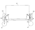
- Drawing 1 is a figure explaining an outline of operation when opening and closing device 1 concerning an embodiment of the present invention is provided in sewers 100U and 100L, and is a figure when the water level of sewer 100U is low ( Figure 1 (a)).
- FIG. 1 (a) The figure when the water level of the sewer 100U is becoming high
- FIG. 1 (c) the gate 10 of the switchgear 1 is shown, other components of the switchgear 1 are not shown in FIG.
- the sewer 100U is on the upstream side, and the sewer 100L side is on the downstream side.
- the switchgear 1 is disposed between the sewer 100U and the sewer 100L through a manhole (not shown).
- the water level of the sewage W flowing through the sewer 100U is low (see FIG. 1 (a)).
- the gate 10 stands and receives a flow of sewage W (a kind of fluid) flowing through the sewer 100U.
- the sewage W is stopped by the gate 10, and the sewage W does not flow into the downstream sewer 100L.
- garbage G is collected by the sewage flowing into the sewer 100L.
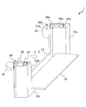
- FIG. 2 is a perspective view of the switchgear 1 (with the gate 10 standing).
- FIG. 3 is a perspective view of the switchgear 1 (a state where the gate 10 is tilted).
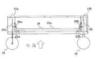
- FIG. 4 is a view of the opening / closing device 1 as viewed from the upstream side (FIG. 4A) and a view as viewed from the downstream side (FIG. 4B).
- the switchgear 1 includes a gate 10, frame columns 12a and 12b, a bottom 12c, a plate 14, a first float 18, a second float 16, a hanging member 34a, an upper fulcrum 36a, a lifting member 38, a hanging member 38a, and a hanging fulcrum. 40, 40a and plates 50, 50a.
- the gate 10 is surrounded by frame pillars 12 a and 12 b standing on the side of the gate 10 and a bottom portion 12 c disposed at the bottom of the gate 10, and is further partially covered by a plate 14.
- the gate 10 When the gate 10 is standing, it receives the water flow and is coughing (see FIG. 2). However, when the water level of the water flow increases and the first float 18 and the second float 16 rise, the gate 10 falls to the downstream side, and fluid such as sewage W flows downstream (see FIG. 3).
- the left side is the upstream side and the right side is the downstream side.
- the specific gravity of the first float 18 and the second float 16 is smaller than the specific gravity of the fluid received with the gate 10 standing.
- the first float 18 and the second float 16 are arranged on the upstream side of the gate 10.
- the second float 16 is disposed on the right side when viewed from the upstream side
- the first float 18 is disposed on the left side when viewed from the upstream side (see also FIG. 7).
- the first float 18 is fixed to the lower end of the drooping member 34a.
- the hanging member 38a is a member in which the hanging member 34a is fixed to the upper fulcrum 36a, and the first float 18 is suspended (see also FIG. 6B).
- the suspension member 38a is fixed to the frame column 12a by a suspension fulcrum 40a.
- the raising member 38 is located above the second float 16.
- the ascending member 38 is fixed to the frame column 12b by a suspension fulcrum 40.
- the hanging member 34a When the first float 18 rises, the hanging member 34a also rises, and the hanging member 38a rotates around the hanging fulcrum 40a so that the upper fulcrum 36a rises.
- the rising portion 380a which is a part of the suspension member 38a, also rises as the first float 18 floats.
- the plate 50 is fixed to the upper part of the frame column 12b.
- the plate 50a is fixed to the upper part of the frame column 12a.
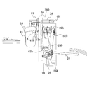
- FIG. 5 is a side view of the switchgear 1, and is a left side view (FIG. 5 (a)) and a right side view (FIG. 5 (b)) as viewed from the upstream side.
- 6 is an enlarged front view (see FIG. 6A) in the vicinity of the floating prevention portion 44 of the switchgear 1 (see from the upstream side) and an enlarged front view in the vicinity of the first float 18 (FIG. 6B).
- FIG. 7 is a plan view seen through the vicinity of the fall prevention portions 20a and 20b in a state where the gate 10 is standing.
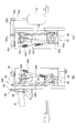
- the switchgear 1 includes the fall prevention units 20b and 20a, the first support release unit 22a, the second support release unit 22b, the floating prevention unit 44, the second float support beam 41, and the floating prevention release unit. 42, a gate rotating shaft 26, a common rotating shaft 28, rotating portions 29b and 29a, descending portions 24b and 24a, a first spring 52a, a second spring (second force generating portion) 52b, and rotating bodies 56a and 56b.
- the gate 10 can be tilted with the hollow gate rotation shaft 26 (see FIG. 13) as the rotation center (rotation shaft).
- the fall prevention portions 20 b and 20 a are in contact with the downstream surface 10 a and give the gate 10 a force against the water flow.
- the fall prevention portions 20 b and 20 a support the downstream surface 10 a of the gate 10.
- the fall prevention units 20b and 20a support the gate 10 to prevent the gate 10 from falling to the downstream side.
- the fall prevention unit 20b is arranged on the right side, and the fall prevention unit 20a is arranged on the left side.
- the first support release portion 22a and the second support release portion 22b are bilaterally symmetric when viewed from the upstream side (even when viewed from the downstream side).
- the first support release unit 22a pulls the fall prevention unit 20a to the outside of the water flow (flow) (left side in FIG. 7), thereby removing the point where the fall prevention unit 20a contacts the gate 10 from the gate 10 and The support of the gate 10 by 20a is released (see FIG. 12).
- the second support release part 22b removes the point where the fall prevention part 20b contacts the gate 10 from the gate 10 by pulling the fall prevention part 20b to the outside (right side in FIG. 7) of the water flow (flow). The support of the gate 10 by 20b is released (see FIG. 12).
- FIG. 5A the second float 16, the anti-floating release portion 42, and the anti-lifting portion 44 that are visible behind the first float 18 are not shown.
- FIG. 5B the first float 18 that is visible behind the second float 16 is not shown. The same applies to other side views (excluding FIG. 14).
- the rising prevention unit 44 prevents the first float 18 from rising.
- the levitation prevention unit 44 includes a collision portion 44b, a fixed portion 44a, and a rotatable portion 44c. In addition, you may make it accommodate the floating prevention part 44 in the frame pillar 12b.
- the collision part 44b is located above the raising member 38 and collides with the raising member 38 when the part where the raising member 38 rises (the part of the raising member 38 that is directly below the collision part 44b) rises.
- the ascending member 38 has an ascending portion 380 that rises as the ascending portion 380a of the hanging member 38a rises.
- the ascending member 38 and the suspending member 38a are connected to the common rotation shaft 28 (extending in the same direction as the rotation center of the gate 10 (gate rotation shaft 26)), the first connection This is because they are connected via the member 62a and the second connecting member 62b.
- the first float 18 rises, the rising portion 380a rises, and the rising portion 380 also rises accordingly.
- the ascending member 38 collides with the collision part 44b, the ascending part 380 cannot also rise and the first float 18 cannot float.
- the fixed portion 44a fixes the collision portion 44b to a portion that is stationary with respect to the flow (for example, the plate 50).
- the collision portion 44b can rotate around the fixed portion 44a. Note that the fixed portion 44a is fixed to the plate 50 in other drawings.
- the rotatable portion 44c is located at the same height as the fixed portion 44a, and is rotatable around the fixed portion 44a.
- collision portion 44b and the rotatable portion 44c are integrated, and the collision portion 44b also rotates around the fixed portion 44a by the angle at which the rotatable portion 44c rotates around the fixed portion 44a.
- the second float support beam 41 is fixed to the frame column 12b at a fulcrum 41a (see FIG. 8) and supports the second float 16.
- the second float support beam 41 is rotatable around a fulcrum 41a.
- the levitation prevention release part (drive part) 42 is rotatably connected to a connection point 41b (disposed upstream of the fulcrum 41a) of the second float support beam 41 (see FIG. 8).
- a connection point 41b disposed upstream of the fulcrum 41a
- the connection point 41b rises.
- the anti-lifting release unit (driving unit) 42 moves up and pushes the rotatable portion 44c upward, and the rotatable portion 44c rotates around the fixed portion 44a.
- the collision part 44b moves from above the ascending member 38 (see FIG. 11), and there is no obstacle that prevents the ascending member 38 from being lifted immediately below the collision part 44b.
- the floating prevention release unit (drive unit) 42 releases the floating prevention of the first float 18 by the floating prevention unit 44 as the second float 16 floats.
- the common rotation shaft 28 is disposed inside the hollow gate rotation shaft 26 and extends in the same direction as the gate rotation shaft 26.
- Rotating portions 29 b and 29 a are fixed to the common rotating shaft 28 and rotate together with the common rotating shaft 28.
- the rotating unit 29b rotates
- the common rotating shaft 28 rotates with the rotation.
- the rotating unit 29a rotates.
- the first connecting member 62a has one end connected to the rising portion 380a of the hanging member 38a and the other end connected to the rotating portion 29a.
- the second connecting member 62b has one end connected to the rising portion 380 of the rising member 38 and the other end connected to the rotating portion 29b.
- the descending portion 24b is fixed so as to be able to rotate at the end of the rotating portion 29b (on the side opposite to the end to which the second connecting member 62b is connected).
- the rotating portion 29b rotates clockwise in FIG. 5B, the descending portion 24b descends accordingly.
- the descending portion 24b is coupled to the ascending member 38 via the second coupling member 62b and the rotating portion 29b. As the ascending portion 380 of the ascending member 38 rises, the rotating portion 29b rotates clockwise in FIG. 5B, and the descending portion 24b descends.
- the descending portion 24a is fixed to the end of the rotating portion 29a so that it can rotate.
- the rotating portion 29a rotates counterclockwise in FIG. 5A (corresponding to clockwise rotation in FIG. 5B)
- the descending portion 24a descends accordingly.
- the descending portion 24a is coupled to the suspension member 38a via the first coupling member 62a and the rotating portion 29a. As the ascending portion 380a of the suspending member 38a rises, the rotating portion 29a rotates counterclockwise in FIG. 5A, and the descending portion 24a descends.
- the rotating part 29a and the descending part 24a constitute a first release operating part.
- the first release actuating part lowers the descending portion 24a and pulls the first support releasing part 22a while rotating the common rotating shaft 28 by the rotating part 29a (counterclockwise rotation in FIG. 5A). Thus, the first support release portion 22a is operated.
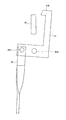
- the first support release portion 22a has a shape bent substantially at a right angle, the horizontal portion is connected to the descending portion 24a, and the portion extending in the vertical direction is the fall-preventing portion. It is connected to 20a and can rotate around a bent portion at a right angle.
- Rotating portion 29b and descending portion 24b constitute a second release operating portion.
- the rotation portion 29b rotates with the rotation of the common rotation shaft 28 (clockwise rotation in FIG. 5B), lowers the descending portion 24b, and pulls the second support release portion 22b. This activates the second support release portion 22b.
- the second support release portion 22b is bent at a substantially right angle, the horizontal portion is connected to the descending portion 24b, and the portion extending in the vertical direction is the fall preventing portion. It is connected to 20b and can rotate around a bent portion at a right angle.
- the second release operation part (rotating part 29b and descending part 24b) and the first release action part (rotating part 29a and descending part 24a) are bilaterally symmetric when viewed from the upstream side (even when viewed from the downstream side). is there.
- the first spring 52a, the second spring (second force generation unit) 52b, and the rotating bodies 56a and 56b will be described later with reference to FIG.
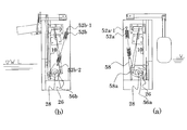
- FIG. 8 is a left side view (FIG. 8 (a)) and a right side view (FIG. 8 (b)) of the switchgear 1 when viewed from the upstream side when the water level of the sewage W is low (denoted as WL). is there.
- FIG. 8 when the level of sewage W (denoted as WL) is low, as described with reference to FIGS. 5 (a) and 5 (b), gate 10 is supported by fall prevention portions 20b and 20a. , Stay standing.
- the water level of the sewage W becomes higher due to rain.
- the first float 18 Since the first float 18 is submerged in the sewage W, and the specific gravity of the first float 18 is smaller than the specific gravity of the sewage W, the first float 18 originally floats and the upper end of the first float 18 is the sewage W. Should exceed the water level. However, the first float 18 does not rise.
- FIG. 10 is a right side view of the switchgear 1 when the water level of the sewage W (indicated as W.L.) becomes higher and the second float 16 floats.
- Both the second float 16 and the first float 18 have a shape that provides sufficient buoyancy for operation.
- the first float 18 may be a foam material.
- the outer diameters of the bottom surfaces of the second float 16 and the first float 18 are equal.
- the second float 16 is thinner in the vertical direction than the first float 18. Therefore, the second float 16 is lighter than the first float 18. This means that when the second float 16 is partially submerged in the sewage W, it is likely to rise rapidly.
- the height at which the second float 16 is disposed is substantially equal to the height at which the upper end of the first float 18 is positioned (see, for example, FIG. 14), the water level of the sewage W reaches near the upper end of the gate 10. Then, the second float 16 is likely to rise rapidly. However, the height at which the upper end of the first float 18 is located is lower than the upper end of the gate 10, but is substantially equal to the height at which the upper end of the gate 10 is located.
- FIG. 11 is an enlarged front view of the vicinity of the floating prevention portion 44 of the opening / closing device 1 when the floating prevention portion 44 rotates.
- the second float 16 When the second float 16 is partially submerged in the sewage W and rapidly rises, the second float support beam 41 rotates around the fulcrum 41a and the connection point 41b rises. Then, the anti-lifting release unit (driving unit) 42 moves up and pushes the rotatable portion 44c upward, and the rotatable portion 44c rotates around the fixed portion 44a. Then, the collision part 44b moves from above the ascending member 38 (see FIG. 11), and there is no obstacle that prevents the ascending member 38 from being lifted immediately below the collision part 44b. Therefore, nothing prevents the rising portion 380a of the suspension member 38a from rising, and nothing prevents the first float 18 from rising.
- the first float 18 since the first float 18 is completely submerged in the sewage W and receives a large buoyancy, the first float 18 rises rapidly. As a result, the suspension member 38a rotates (counterclockwise in FIG. 5A) about the suspension fulcrum 40a.
- the first connecting member 62a rises, and the rotating portion 29a lowers the descending portion 24a while rotating the common rotating shaft 28 (counterclockwise in FIG. 5A).
- the first support release portion 22a rotates clockwise in FIG. 13C, and the fall prevention portion 20a moves outside the flow (left side in FIG. 7). ),
- the first support release portion 22a operates. Therefore, the fall prevention unit 20a is detached from the gate 10 (see FIG. 12).
- FIG. 13 is a right side view (FIG. 13A), a left side view (FIG. 13B) when the switching device 1 is viewed from the downstream side, and a diagram when the switching device 1 is viewed from the downstream side (FIG. 13). (C)).
- the common rotation shaft 28 is seen through, and further, the first release operation part (the rotation part 29a and the lowering part 24a) and the second release operation part (the rotation part 29b and the lowering part 24b),
- the fall prevention units 20b and 20a, the first support release unit 22a, and the second support release unit 22b are illustrated.
- the first support release portion is associated with the floating of the first float 18 (in addition, “floating” does not necessarily require the upper end to be exposed to the water surface, and includes that the upper end moves toward the water surface). 22a and the second support release part 22b operate.
- FIG. 12 is a plan view of the vicinity of the fall prevention portions 20a and 20b in a state where the gate 10 has fallen. Since the fall prevention parts 20a and 20b are detached from the gate 10, the gate 10 falls down downstream due to the water pressure of the sewage W.
- FIG. 14 is a right side view of the switchgear 1 after the sewage W has flowed downstream. If the water level becomes lower than the lower end of the second float 16 due to the sewage W flowing downstream, the first float 18 descends while floating on the surface of the sewage W. Thereby, the raising member 38 also returns to the horizontal. In addition, the second float 16 is lowered, the connection point 41b is also lowered, and the levitation preventing portion 44 is also returned to the position where the ascending member 38 is suppressed (see FIG. 6A).
- the rising prevention portion 44 holds down the ascending member 38 until the second float 16 floats (FIG. 6A )), The first float 18 cannot rise.
- the rise prevention unit 44 rotates accordingly, and the ascending member 38 cannot be restrained (see FIG. 11), and the first float 18 starts to rise rapidly (already already). Submerged, and a large buoyancy is acting on the first float 18).
- the suspension member 38a rotates about the fulcrum 40a in the counterclockwise direction in FIG. 5A, and the first connecting member 62a rises, so that the rotating portion 29a rotates counterclockwise, and the descending portion 24a descends, the first support release part 22a is pulled (see FIG. 13), the fall prevention part 20a is pulled, and the support of the gate 10 is released.
- the rotating portion 29a rotates, the common rotating shaft 28 rotates, the rotating portion 29b rotates (clockwise in FIG. 5B), the descending portion 24b descends, and the second support releasing portion 22b. Is pulled (see FIG. 13), the fall prevention part 20b is pulled, and the support of the gate 10 is released.
- the operation is transmitted by pulling so that the support of the gate 10 is released simultaneously by the fall prevention units 20a and 20b.
- the fall prevention portions 20a and 20b are connected by the common rotary shaft 28, and the common rotary shaft 28 enters the hollow gate rotary shaft 26, and the sewage W is inside the gate rotary shaft 26. Since it does not enter, the common rotating shaft 28 is not exposed to the sewage W.
- the second float 16 since the first float 18 (left side, see FIG. 7) is on the opposite side of the second float 16 (right side, see FIG. 7) when viewed from the upstream side, the second float is placed on the first float 18. Compared with a certain prior art 16, the second float 16 does not get in the way when working on the first float 18. Therefore, the operation
- the shape and dimensions of the first float 18 are greatly restricted so as not to hinder the operation of the second float 16. For example, it is restricted to increase the thickness of the first float 18 in the vertical direction. For this reason, the buoyancy required for the first float 18 is limited and the buoyancy required for the first float 18 may not be sufficiently secured.
- the first float 18 (left side, see FIG. 7) is on the opposite side of the second float 16 (right side, see FIG. 7) when viewed from the upstream side.
- One float 18 hardly inhibits the operation of the second float 16.
- the shape and dimension of the first float 18 are hardly restricted by the second float 16.
- the thickness of the first float 18 in the vertical direction can be increased so that sufficient buoyancy required for the first float 18 can be secured.
- the left and right eccentricity of the member that suspends and penetrates the first float 18 is reduced (the upper and lower through-holes of the first float 18).
- a mechanism for suspending and holding the penetrating member is provided below the first float 18.
- the first float 18 is suspended, the first float 18 is not penetrated up and down, so that a holding mechanism need not be provided below the first float 18. For this reason, there is no adherence of contaminants to the holding mechanism (causing malfunction). In addition, the number of parts of the switchgear is reduced, which can contribute to the improvement of maintenance.
- the opening / closing device 1 returns to the state where the gate 10 stands when the water level in the flow path becomes low after the gate 10 falls down.
- FIG. 15 is a side view of the switchgear 1 when the gate 10 falls down, and is a left side view (FIG. 15 (a)) and a right side view (FIG. 15 (b)) as viewed from the upstream side.
- the opening / closing device 1 includes the first spring 52a, the second spring (second force generation unit) 52b, and the rotating bodies 56a and 56b. Further, the opening / closing device 1 has a link 58.
- Rotating bodies 56 a and 56 b are fixed to the gate rotation shaft 26 and rotate together with the gate rotation shaft 26.
- the first force generator is composed of a first spring 52a and a link 58.
- the first spring 52a is fixed to one end 52a-1 of the first force generator.
- the link 58 is fixed to the other end 58a of the first force generator and is connected to the first spring 52a.
- the one end 52a-1 of the first force generator is fixed above the gate rotation shaft 26.
- the other end 58a of the first force generation unit is fixed to the rotating body 56a and the other end 58a of the first force generation unit is disposed at a position separated from the gate rotation shaft 26 (center) by a predetermined length. ing. That is, even if the rotating body 56a rotates together with the gate rotation shaft 26, the distance (predetermined length) between the other end 58a of the first force generator and the gate rotation shaft 26 (the center thereof) does not change.
- the first spring 52a generates a force that returns the gate 10 to a standing state. However, the first spring 52a generates a force that is not sufficient to bring the gate 10 into a standing state when the gate 10 is tilted.
- the straight line connecting one end 52a-1 of the first force generating portion and the other end 58a of the first force generating portion when the gate 10 is tilted The distance D1 from the center (corresponding to the length of a perpendicular line extending from the center of the gate rotation shaft 26 to the straight line connecting the one end 52a-1 and the other end 58a) is short. Therefore, the torque for rotating the gate rotation shaft 26 clockwise in FIG. 15A is small, and the force is not sufficient to keep the gate 10 standing.
- the second force generator has a second spring 52b fixed to both one end 52b-1 of the second force generator and the other end 52b-2 of the second force generator.
- the second spring 52b is fixed to one end 52b-1 (or the other end 52b-2)
- the link is connected to the other end 52b-2 (or one end 52b-1)
- the second spring 52b is connected to the link. It is also conceivable to do so.
- the one end 52b-1 of the second force generator is fixed above the gate rotation shaft 26.
- the other end 52b-2 of the second force generating portion is fixed to the rotating body 56b, and is disposed at a position away from the gate rotation shaft 26 (the center) by a predetermined length. That is, even if the rotating body 56b rotates with the gate rotation shaft 26, the distance (predetermined length) between the other end 52b-2 of the second force generating portion and the gate rotation shaft 26 (the center thereof) does not change.
- a distance D2 between a straight line connecting one end 52b-1 of the second force generation unit and the other end 52b-2 of the second force generation unit and the rotation center of the gate rotation shaft 26 in a state where the gate 10 is tilted. (Corresponding to the length of a perpendicular line drawn from the center of the gate rotation shaft 26 to the straight line connecting the one end 52b-1 and the other end 52b-2) is longer than the distance D1.
- the second spring 52b is longer than the first spring 52a (the spring constant is small), and the torque to be rotated counterclockwise in FIG. 15B is small.
- the gate 10 By adjusting the distance D2 and the length by which the second spring 52b is contracted, when the water level of the flow path through which the fluid (sewage W) flows is equal to or lower than the predetermined water level, the gate 10 starts to stand. To generate sufficient force. However, the force of the second spring 52b is increased too much so that sufficient force is not generated to start the gate 10 standing while the water level in the flow path is still high.
- the gate rotating shaft 26 is rotated by the contraction force of the second spring 52b, and the gate 10 is slightly raised.
- FIG. 16 is a side view of the switchgear 1 when the gate 10 is slightly raised, and is a left side view (FIG. 16 (a)) and a right side view (FIG. 16 (b)) as viewed from the upstream side.
- gate 10 goes up.
- FIG. 17 is a side view of the switchgear 1 when the gate 10 is further raised, and is a left side view (FIG. 17 (a)) and a right side view (FIG. 17 (b)) as viewed from the upstream side.
- the distance D3 from the center of the gate rotation shaft 26 is long. That is, when the gate 10 is tilted (see FIG. 15A), the straight line connecting the one end 52a-1 of the first force generating portion and the other end 58a of the first force generating portion, The distance D1 from the center is shorter than the distance D3. The same is true when the body is tilted by less than a predetermined angle (when the gate 10 is standing more than in FIG. 17A).
- the first spring 52a when the gate 10 is tilted by a predetermined angle or less, the first spring 52a generates a force sufficient to bring the gate 10 into a standing state. That is, the torque for rotating the gate rotation shaft 26 generated by the first spring 52a clockwise (torque for raising the gate 10) is sufficiently large to make the gate 10 stand.
- FIG. 18 is a side view of the switchgear 1 with the gate 10 standing, and is a left side view (FIG. 18A) and a right side view (FIG. 18B) as viewed from the upstream side.
- the gate rotating shaft 26 is on a straight line connecting one end 52b-1 of the second force generating portion and the other end 52b-2 of the second force generating portion, and the second spring
- the torque generated by 52b for rotating the gate rotation shaft 26 counterclockwise is substantially zero.
- the torque for bringing the gate 10 up by the first spring 52a having a large spring constant is small. It is possible to prevent the gate 10 from being closed while the water level of the flow path is high.
- the first spring 52a when the gate 10 is tilted by a predetermined angle or less (see FIG. 17A), the first spring 52a generates a force sufficient to bring the gate 10 into a standing state. Therefore, the gate 10 can be made to stand.
- the gate 10 falls (see FIG. 15B), it is sufficient to start the gate 10 standing when the water level of the flow path through which the fluid (sewage W) flows is below a predetermined water level.
- the gate 10 can be started to stand by the second spring 52b that generates a large force.
Landscapes
- Engineering & Computer Science (AREA)
- General Engineering & Computer Science (AREA)
- Structural Engineering (AREA)
- Mechanical Engineering (AREA)
- Civil Engineering (AREA)
- Water Supply & Treatment (AREA)
- Public Health (AREA)
- Hydrology & Water Resources (AREA)
- Life Sciences & Earth Sciences (AREA)
- Health & Medical Sciences (AREA)
- Barrages (AREA)
- Sewage (AREA)
- Devices For Checking Fares Or Tickets At Control Points (AREA)
Abstract
Description
Claims (7)
- 流体の流れを受け、該流れの下流方向に倒れることが可能なゲートと、
前記ゲートを支持することにより、前記ゲートが倒れることを防止する倒れ防止部と、
前記倒れ防止部による前記ゲートの支持を解除する支持解除部と、
前記ゲートよりも上流側に配置され、上流から見て前記ゲートの左側および右側の一方に配置され、前記流体よりも比重が小さい第一フロートと、
前記第一フロートの浮上を防止する浮上防止部と、
前記ゲートよりも上流側に配置され、上流から見て前記ゲートの左側および右側の他方に配置され、前記流体よりも比重が小さい第二フロートと、
前記第二フロートの浮上に伴い、前記浮上防止部による前記第一フロートの浮上の防止を解除する浮上防止解除部と、
を備え、
前記第一フロートの浮上に伴い、前記支持解除部が作動する、
開閉装置。 - 請求項1に記載の開閉装置であって、
前記倒れ防止部は、前記ゲートの下流側の面を支持する、
開閉装置。 - 請求項1に記載の開閉装置であって、
前記支持解除部は、前記倒れ防止部を前記流れの外側に引っ張ることにより、前記ゲートの支持を解除する、
開閉装置。 - 請求項1に記載の開閉装置であって、
前記第一フロートを吊り下げ、前記第一フロートの浮上に伴い上昇する部分を有する吊り下げ部材と、
前記第二フロートの上方に位置し、前記吊り下げ部材の前記上昇する部分の上昇に伴い上昇する部分を有する上昇部材と、
を備え、
前記浮上防止部は、
前記上昇部材の上方に位置し、前記上昇部材の上昇する部分の上昇時に前記上昇部材に衝突する衝突部分と、
前記流れに対して静止している部分に、前記衝突部分を回転可能に固定する固定部分と、
を有する、
開閉装置。 - 請求項4に記載の開閉装置であって、
前記上昇部材と前記吊り下げ部材とが、前記ゲートの回転中心と同じ方向に延伸する回転軸を介して、連結されている、
開閉装置。 - 請求項4または5に記載の開閉装置であって、
前記浮上防止部は、
前記固定部分を中心として回転可能な回転可能部分を有し、
しかも、前記回転可能部分が回転した角度だけ、前記衝突部分も回転するものであり、
前記浮上防止解除部は、
前記第二フロートの浮上に伴い、前記回転可能部分を動かす駆動部を有する、
開閉装置。 - 請求項4または5に記載の開閉装置であって、
前記吊り下げ部材に連結され、前記吊り下げ部材の上昇する部分の上昇に伴って下降する下降部分を備え、
前記支持解除部は、前記倒れ防止部を前記流れの外側に引っ張ることにより、前記ゲートの支持を解除し、
さらに、前記支持解除部は、前記下降部分に連結され、前記下降部分の下降を受けて、前記倒れ防止部を前記流れの外側に引っ張る、
開閉装置。
Priority Applications (8)
| Application Number | Priority Date | Filing Date | Title |
|---|---|---|---|
| MYPI2017704585A MY190918A (en) | 2015-06-05 | 2015-06-18 | Opening/closing device |
| EP15894270.6A EP3309301B1 (en) | 2015-06-05 | 2015-06-18 | Opening and closing device |
| AU2015397438A AU2015397438B2 (en) | 2015-06-05 | 2015-06-18 | Opening and closing device |
| SG11201709984WA SG11201709984WA (en) | 2015-06-05 | 2015-06-18 | Opening/closing device |
| CA2987554A CA2987554C (en) | 2015-06-05 | 2015-06-18 | Opening/closing device |
| KR1020177034991A KR102294110B1 (ko) | 2015-06-05 | 2015-06-18 | 개폐 장치 |
| US15/572,623 US10415201B2 (en) | 2015-06-05 | 2015-06-18 | Opening/closing device |
| PH12017502217A PH12017502217B1 (en) | 2015-06-05 | 2017-12-05 | Opening/closing device |
Applications Claiming Priority (2)
| Application Number | Priority Date | Filing Date | Title |
|---|---|---|---|
| JP2015114450A JP6277156B2 (ja) | 2015-06-05 | 2015-06-05 | 開閉装置 |
| JP2015-114450 | 2015-06-05 |
Publications (1)
| Publication Number | Publication Date |
|---|---|
| WO2016194237A1 true WO2016194237A1 (ja) | 2016-12-08 |
Family
ID=57440305
Family Applications (1)
| Application Number | Title | Priority Date | Filing Date |
|---|---|---|---|
| PCT/JP2015/067647 Ceased WO2016194237A1 (ja) | 2015-06-05 | 2015-06-18 | 開閉装置 |
Country Status (10)
| Country | Link |
|---|---|
| US (1) | US10415201B2 (ja) |
| EP (1) | EP3309301B1 (ja) |
| JP (1) | JP6277156B2 (ja) |
| KR (1) | KR102294110B1 (ja) |
| AU (1) | AU2015397438B2 (ja) |
| CA (1) | CA2987554C (ja) |
| MY (1) | MY190918A (ja) |
| PH (1) | PH12017502217B1 (ja) |
| SG (1) | SG11201709984WA (ja) |
| WO (1) | WO2016194237A1 (ja) |
Cited By (1)
| Publication number | Priority date | Publication date | Assignee | Title |
|---|---|---|---|---|
| CN107893408A (zh) * | 2017-12-07 | 2018-04-10 | 刘曼华 | 一种水面漂浮垃圾的垃圾收集装置 |
Families Citing this family (3)
| Publication number | Priority date | Publication date | Assignee | Title |
|---|---|---|---|---|
| CN109629659B (zh) * | 2018-10-31 | 2021-05-07 | 河南中拓石油工程技术股份有限公司 | 一种市政排水管道清淤装置及清淤工艺 |
| CN109958184B (zh) * | 2019-04-17 | 2020-09-18 | 同济大学 | 排水管道冲刷拦截装置 |
| CN110984082B (zh) * | 2019-12-27 | 2024-05-03 | 贵州省水利水电勘测设计研究院 | 一种渠道平面闸门双向止水结构 |
Citations (5)
| Publication number | Priority date | Publication date | Assignee | Title |
|---|---|---|---|---|
| JP2004360280A (ja) * | 2003-06-04 | 2004-12-24 | Kubota Corp | フラッシュゲート |
| JP2008106461A (ja) * | 2006-10-24 | 2008-05-08 | Kubota Corp | フラッシュゲート |
| JP2010180567A (ja) * | 2009-02-04 | 2010-08-19 | Nippon Koei Co Ltd | 開閉装置 |
| JP2010180566A (ja) * | 2009-02-04 | 2010-08-19 | Nippon Koei Co Ltd | 開閉装置 |
| JP2010180568A (ja) * | 2009-02-04 | 2010-08-19 | Nippon Koei Co Ltd | 開閉装置 |
Family Cites Families (4)
| Publication number | Priority date | Publication date | Assignee | Title |
|---|---|---|---|---|
| JPS5166309A (en) | 1974-12-06 | 1976-06-08 | Shikoku Chem | Jinzosekibanno seizoho |
| FR2833978B1 (fr) * | 2001-12-20 | 2005-04-15 | Andre Pierre Simon | Dispositif de chasse automatique a clapet |
| NL1021680C2 (nl) | 2002-10-17 | 2004-05-11 | Tbs Soest B V | Vlotterklep, vlotterstuw en werkwijze voor het gebruik daarvan. |
| DE10320308B3 (de) * | 2003-05-06 | 2004-06-03 | Giehl, Klaus-Ulrich, Dipl.-Ing. (FH) | Schwallspülvorrichtung zur Reinigung von Abwasserkanälen |
-
2015
- 2015-06-05 JP JP2015114450A patent/JP6277156B2/ja active Active
- 2015-06-18 WO PCT/JP2015/067647 patent/WO2016194237A1/ja not_active Ceased
- 2015-06-18 KR KR1020177034991A patent/KR102294110B1/ko active Active
- 2015-06-18 US US15/572,623 patent/US10415201B2/en active Active
- 2015-06-18 SG SG11201709984WA patent/SG11201709984WA/en unknown
- 2015-06-18 EP EP15894270.6A patent/EP3309301B1/en active Active
- 2015-06-18 AU AU2015397438A patent/AU2015397438B2/en active Active
- 2015-06-18 MY MYPI2017704585A patent/MY190918A/en unknown
- 2015-06-18 CA CA2987554A patent/CA2987554C/en active Active
-
2017
- 2017-12-05 PH PH12017502217A patent/PH12017502217B1/en unknown
Patent Citations (5)
| Publication number | Priority date | Publication date | Assignee | Title |
|---|---|---|---|---|
| JP2004360280A (ja) * | 2003-06-04 | 2004-12-24 | Kubota Corp | フラッシュゲート |
| JP2008106461A (ja) * | 2006-10-24 | 2008-05-08 | Kubota Corp | フラッシュゲート |
| JP2010180567A (ja) * | 2009-02-04 | 2010-08-19 | Nippon Koei Co Ltd | 開閉装置 |
| JP2010180566A (ja) * | 2009-02-04 | 2010-08-19 | Nippon Koei Co Ltd | 開閉装置 |
| JP2010180568A (ja) * | 2009-02-04 | 2010-08-19 | Nippon Koei Co Ltd | 開閉装置 |
Non-Patent Citations (1)
| Title |
|---|
| HIDEKI KOREYASU ET AL.: "Gesuido Kanro no Jido Senjo Sochi (Flash Gate) no Sadosei to Koka ni Kansuru Chukan Hokoku", PROCEEDINGS OF SEWAGE RESEARCH CONFERENCE, vol. 48, 8 July 2011 (2011-07-08), pages 578 - 580, XP009504664 * |
Cited By (1)
| Publication number | Priority date | Publication date | Assignee | Title |
|---|---|---|---|---|
| CN107893408A (zh) * | 2017-12-07 | 2018-04-10 | 刘曼华 | 一种水面漂浮垃圾的垃圾收集装置 |
Also Published As
| Publication number | Publication date |
|---|---|
| EP3309301A4 (en) | 2019-04-17 |
| EP3309301A1 (en) | 2018-04-18 |
| EP3309301B1 (en) | 2020-11-25 |
| JP6277156B2 (ja) | 2018-02-07 |
| CA2987554A1 (en) | 2016-12-08 |
| MY190918A (en) | 2022-05-19 |
| KR102294110B1 (ko) | 2021-08-26 |
| US10415201B2 (en) | 2019-09-17 |
| PH12017502217B1 (en) | 2023-10-11 |
| PH12017502217A1 (en) | 2018-06-11 |
| KR20180015649A (ko) | 2018-02-13 |
| SG11201709984WA (en) | 2017-12-28 |
| US20180135266A1 (en) | 2018-05-17 |
| AU2015397438A1 (en) | 2017-12-14 |
| AU2015397438B2 (en) | 2020-09-10 |
| CA2987554C (en) | 2021-04-20 |
| JP2017002483A (ja) | 2017-01-05 |
Similar Documents
| Publication | Publication Date | Title |
|---|---|---|
| JP5166309B2 (ja) | 開閉装置 | |
| JP5166311B2 (ja) | 開閉装置 | |
| JP6277156B2 (ja) | 開閉装置 | |
| JP5905152B1 (ja) | フラップゲート | |
| CN104060656B (zh) | 一种多层水封装置、多层水封方法 | |
| JP5166310B2 (ja) | 開閉装置 | |
| JP2009299308A (ja) | 逆流防止構造及び排水施設 | |
| JP2015137715A (ja) | フロート式逆流防止弁 | |
| JP2007270489A (ja) | 汚水処理ポンプ設備 | |
| JP2008291611A (ja) | 壁排水型ターントラップ式水洗便器 |
Legal Events
| Date | Code | Title | Description |
|---|---|---|---|
| 121 | Ep: the epo has been informed by wipo that ep was designated in this application |
Ref document number: 15894270 Country of ref document: EP Kind code of ref document: A1 |
|
| WWE | Wipo information: entry into national phase |
Ref document number: 15572623 Country of ref document: US |
|
| ENP | Entry into the national phase |
Ref document number: 2987554 Country of ref document: CA |
|
| WWE | Wipo information: entry into national phase |
Ref document number: 11201709984W Country of ref document: SG |
|
| ENP | Entry into the national phase |
Ref document number: 20177034991 Country of ref document: KR Kind code of ref document: A |
|
| WWE | Wipo information: entry into national phase |
Ref document number: 12017502217 Country of ref document: PH |
|
| NENP | Non-entry into the national phase |
Ref country code: DE |
|
| ENP | Entry into the national phase |
Ref document number: 2015397438 Country of ref document: AU Date of ref document: 20150618 Kind code of ref document: A |
|
| WWE | Wipo information: entry into national phase |
Ref document number: 2015894270 Country of ref document: EP |