WO2016194397A1 - 温水暖房システム、制御装置および制御方法 - Google Patents
温水暖房システム、制御装置および制御方法 Download PDFInfo
- Publication number
- WO2016194397A1 WO2016194397A1 PCT/JP2016/051650 JP2016051650W WO2016194397A1 WO 2016194397 A1 WO2016194397 A1 WO 2016194397A1 JP 2016051650 W JP2016051650 W JP 2016051650W WO 2016194397 A1 WO2016194397 A1 WO 2016194397A1
- Authority
- WO
- WIPO (PCT)
- Prior art keywords
- gain
- room temperature
- temperature
- hot water
- command
- Prior art date
- Legal status (The legal status is an assumption and is not a legal conclusion. Google has not performed a legal analysis and makes no representation as to the accuracy of the status listed.)
- Ceased
Links
Images






Classifications
-
- F—MECHANICAL ENGINEERING; LIGHTING; HEATING; WEAPONS; BLASTING
- F24—HEATING; RANGES; VENTILATING
- F24D—DOMESTIC- OR SPACE-HEATING SYSTEMS, e.g. CENTRAL HEATING SYSTEMS; DOMESTIC HOT-WATER SUPPLY SYSTEMS; ELEMENTS OR COMPONENTS THEREFOR
- F24D3/00—Hot-water central heating systems
-
- F—MECHANICAL ENGINEERING; LIGHTING; HEATING; WEAPONS; BLASTING
- F24—HEATING; RANGES; VENTILATING
- F24F—AIR-CONDITIONING; AIR-HUMIDIFICATION; VENTILATION; USE OF AIR CURRENTS FOR SCREENING
- F24F11/00—Control or safety arrangements
- F24F11/30—Control or safety arrangements for purposes related to the operation of the system, e.g. for safety or monitoring
-
- F—MECHANICAL ENGINEERING; LIGHTING; HEATING; WEAPONS; BLASTING
- F24—HEATING; RANGES; VENTILATING
- F24D—DOMESTIC- OR SPACE-HEATING SYSTEMS, e.g. CENTRAL HEATING SYSTEMS; DOMESTIC HOT-WATER SUPPLY SYSTEMS; ELEMENTS OR COMPONENTS THEREFOR
- F24D3/00—Hot-water central heating systems
- F24D3/18—Hot-water central heating systems using heat pumps
-
- F—MECHANICAL ENGINEERING; LIGHTING; HEATING; WEAPONS; BLASTING
- F24—HEATING; RANGES; VENTILATING
- F24F—AIR-CONDITIONING; AIR-HUMIDIFICATION; VENTILATION; USE OF AIR CURRENTS FOR SCREENING
- F24F11/00—Control or safety arrangements
- F24F11/62—Control or safety arrangements characterised by the type of control or by internal processing, e.g. using fuzzy logic, adaptive control or estimation of values
-
- F—MECHANICAL ENGINEERING; LIGHTING; HEATING; WEAPONS; BLASTING
- F24—HEATING; RANGES; VENTILATING
- F24F—AIR-CONDITIONING; AIR-HUMIDIFICATION; VENTILATION; USE OF AIR CURRENTS FOR SCREENING
- F24F2110/00—Control inputs relating to air properties
- F24F2110/10—Temperature
-
- F—MECHANICAL ENGINEERING; LIGHTING; HEATING; WEAPONS; BLASTING
- F24—HEATING; RANGES; VENTILATING
- F24F—AIR-CONDITIONING; AIR-HUMIDIFICATION; VENTILATION; USE OF AIR CURRENTS FOR SCREENING
- F24F2221/00—Details or features not otherwise provided for
- F24F2221/18—Details or features not otherwise provided for combined with domestic apparatus
- F24F2221/183—Details or features not otherwise provided for combined with domestic apparatus combined with a hot-water boiler
Definitions
- the present invention relates to a hot water heating system for heating a building, a control device and a control method for the hot water heating system.
- a hot water heating system that heats by circulating hot water heated by heat generated by a heat source device using a heat pump is known. Further, in the control of the hot water heating system, it is known that the heat source machine is repeatedly stopped and driven according to the room temperature or the like for reasons such as energy saving. Specifically, when the set temperature is lower than room temperature, or when the air conditioning load is so low that the required amount of heat is lower than the minimum value when the heat source device is operated, the heat source device is stopped. Then, after the heat source machine is stopped, the operation of the heat source machine is resumed when the room temperature decreases due to the influence of outside air or the like as time passes and the room temperature becomes lower than the set temperature.
- Patent Literature 1 describes a hot water heating apparatus that detects the temperature of hot water on the forward path side and performs feedback control in accordance with a preset target temperature.
- the hot water heater of Patent Document 1 when the forward water temperature rises to a predetermined fire extinguishing temperature, the operation of the heat source machine is stopped, and the forward water temperature reaches a predetermined reignition temperature lower than the target temperature. When it falls, the operation of the heat source machine is resumed.
- the heat source machine When controlling the tapping temperature in a hot water heater such as a radiator or floor heating to match the set temperature, it is necessary to stop the operation of the heat source unit if the required heat amount is less than the minimum heat generation amount of the heat source unit When the tapping temperature falls below the set temperature, it is necessary to restart the operation of the heat source machine.
- the heat source machine when the operation of the heat source machine is resumed, the heat source machine is controlled by a preset heat supply command that does not take into account the actual heat characteristics of the building. In this case, if the preset heat supply command is larger than the amount of heat originally required for the building, the tapping temperature may exceed the upper limit value and stop again, and the operation and stop are repeated in a short time. There is.
- the durability and energy saving performance of the actuator are deteriorated.
- the preset heat supply command is less than the amount of heat that is originally required, the temperature of the hot water does not rise sufficiently, so that the room temperature is difficult to rise and comfort is impaired.
- the set temperature of heating may be lowered in the absence or at night, and the heat supply by the heat source machine may be stopped. If the room temperature falls below the set temperature, the set temperature of heating is set when returning home or in the morning. The heat source machine restarts the heat supply, for example, by raising it. At this time, if heat supply is resumed with a preset hot water temperature command, a hot water temperature command information that has been adjusted by heating control until immediately before the heat supply is stopped cannot be used, and feedback control is started from the beginning. Will be re-partitioned. As a result, the heating control becomes discontinuous, and the time required to stabilize the room temperature becomes long. Especially in a highly airtight / highly insulated house, if the set temperature rises before the room temperature has fallen to the set temperature, it takes time for the room temperature to reach the set temperature due to the discontinuity of the heating control. Will be damaged.
- the present invention has been made to solve the above-described problems, and an object thereof is to provide a hot water heating system, a control device, and a control method that realize energy saving without impairing comfort.
- a warm water heating system includes a room temperature sensor that detects room temperature information of a building, a heat source that generates warm water, an indoor unit that heats the building by releasing the heat of the warm water generated by the heat source, and a heat source.
- a heat source unit that compresses the refrigerant, a refrigerant-water heat exchanger that exchanges heat between the refrigerant and water, and a hot-water refrigerant-water heat exchanger and an indoor unit.
- the control device uses a control gain determination unit that calculates the first gain and the second gain based on the thermal characteristics of the building, and the first gain and the second gain.
- the heating control unit that updates the tapping temperature command, which is the target value of the water outlet temperature of the refrigerant-water heat exchanger, and the heating control unit are updated when the indoor unit is turned on by air conditioning to supply heat to the building.
- Hot water supply that issues a heat supply command to the heat source unit based on the hot water temperature command
- the first gain is designed to obtain a tapping temperature command that provides a desired room temperature response when the air conditioner is ON, and the second gain It is designed to obtain a tapping temperature command that reflects a change in room temperature when air conditioning is off without supplying heat to the heating control unit.
- the hot water temperature command is updated using the gain, and when the air conditioning is OFF, the hot water temperature command is updated using the set temperature, room temperature information, and the second gain.
- the hot water temperature command is updated using the set temperature, room temperature information, and the second gain even when the air conditioning is OFF.
- the operation is resumed based on the updated hot water temperature command, and the hot water temperature from the air conditioning OFF to the air conditioning ON can be made continuous. Therefore, the state before the air conditioning is turned off can be taken over, and an energy saving effect can be obtained without impairing the room temperature comfort.
- Embodiment 1 of this invention It is a schematic block diagram of the hot water heating system in Embodiment 1 of this invention. It is a schematic block diagram of the warm water circulation circuit in Embodiment 1 of this invention. It is a functional block diagram of the control apparatus in Embodiment 1 of this invention. It is a figure which shows the flow of the heating control by the heating control part in the Embodiment 1 of this invention, a tapping temperature control part, a system identification part, and a control gain determination part. It is a flowchart which shows the flow of the system identification process in Embodiment 1 of this invention. It is a figure which shows the example of the sampling in the system identification part of Embodiment 1 of this invention. It is a block diagram of the heating control part in Embodiment 1 of this invention.
- Embodiment 1 of this invention It is a flowchart which shows the flow of the heating control process in Embodiment 1 of this invention. It is a figure which shows an example of the simulation result of the hot water heating system in Embodiment 1 of this invention. It is a figure which shows the flow of the heating control by the heating control part in the Embodiment 2 of this invention, a tapping temperature control part, a system identification part, and a control gain determination part. It is a block diagram of the heating control part in Embodiment 2 of this invention.
- (A) is a thermal circuit network model to be controlled
- (b) is a thermal circuit network model when there is a heat quantity supplied from the indoor unit
- (c) is a case where there is no heat quantity supplied from the indoor unit. It is a thermal network model.
- Embodiment 3 of this invention It is a schematic block diagram of the warm water circulation circuit in Embodiment 3 of this invention. It is a functional block diagram of the control apparatus in Embodiment 3 of this invention. It is a figure which shows the flow of the heating control by the heating control part in the Embodiment 3 of this invention, a tapping temperature control part, a system identification part, and a control gain determination part. It is an example of the determination of the gain selection signal in Embodiment 3 of this invention. It is a flowchart which shows the flow of the system identification process in Embodiment 3 of this invention. It is a flowchart which shows the flow of the heating control process (at the time of air-conditioning OFF) in Embodiment 3 of this invention. It is a figure which shows the flow of the heating control by the heating control part using the return temperature information in Embodiment 3 of this invention, a tapping temperature control part, a system identification part, and a control gain determination part.
- FIG. FIG. 1 is a schematic configuration diagram of a hot water heating system 100 according to Embodiment 1 of the present invention.
- the hot water heating system 100 includes a room temperature sensor 2 that measures the room temperature of the house 1 that is the building to be heated, a heat source unit 3 that generates hot water used for heating, and the room temperature detected by the room temperature sensor 2 matches the set temperature.
- the controller 4 is configured to give a heat supply command to the heat source unit 3, and the indoor unit 5 discharges the heat of the hot water supplied from the heat source unit 3 into the room for heating.
- FIG. 2 is a schematic configuration diagram of the hot water circulation circuit in the present embodiment.
- the hot water circulation circuit is configured by connecting a heat source device 3 having a heat pump cycle and an indoor heat exchanger 51 provided in the indoor unit 5.
- the heat source device 3 includes a compressor 31, an outdoor heat exchanger 32, a fan 33, a refrigerant flow rate adjustment device 34, a refrigerant-water heat exchanger 35, and a circulation pump 36.
- the heat source machine 3 includes a heat source machine control unit 37 that controls each part of the heat source machine 3.
- the compressor 31, the outdoor heat exchanger 32, the refrigerant flow rate adjustment device 34, and the refrigerant-water heat exchanger 35 are connected in series by a heat source side channel 30.
- a refrigerant for transporting heat is circulated in the heat source side flow path 30.
- the refrigerant-water heat exchanger 35, the indoor heat exchanger 51, and the circulation pump 36 are connected in series by the use side flow path 50.
- water is circulated as a heat medium for conveying heat.
- the compressor 31 compresses the refrigerant sucked from the suction side and discharges it from the discharge side as a high-temperature and high-pressure gas refrigerant.
- the outdoor heat exchanger 32 functions as a refrigerant evaporator during heating operation, performs heat exchange between the outdoor air and the refrigerant, and absorbs heat from the outdoor air.
- the fan 33 blows air to the outdoor heat exchanger 32 and adjusts heat absorption in the outdoor heat exchanger 32.
- the refrigerant flow rate adjusting device 34 is, for example, an electronic expansion valve, and adjusts the flow rate of the refrigerant flowing through the refrigerant-water heat exchanger 35.
- the refrigerant-water heat exchanger 35 functions as a refrigerant condenser during heating operation, and performs heat exchange between the refrigerant circulating in the heat source side channel 30 and the water circulating in the use side channel 50. Thereby, the heat source side flow path 30 and the use side flow path 50 which are independent from each other are thermally connected. In addition, as a heat medium which circulates in the utilization side flow path 50, you may use an antifreeze or a liquid mixture of water and an antifreeze instead of water.
- the circulation pump 36 adjusts the flow rate of the hot water heated via the refrigerant-water heat exchanger 35.
- the hot water circulating in the use side flow path 50 releases heat by the indoor heat exchanger 51 and is heated again through the refrigerant-water heat exchanger 35.
- the heat source unit 3 is provided on the outlet side of the refrigerant-water heat exchanger 35 in the use-side flow path 50, and is provided on the outlet side of the hot water temperature sensor 21 for detecting the hot water temperature and on the inlet side of the refrigerant-water heat exchanger 35.
- a return temperature sensor 22 that detects the return temperature of the water that has been circulated through the indoor heat exchanger 51 and a flow rate sensor 23 that detects the flow rate of the water circulating in the use-side flow path 50 are provided. Information detected by these sensors is transmitted to the heat source machine control unit 37 by analog communication or digital communication.
- the heat source device control unit 37 operates the operation capacity of the compressor 31, the air volume of the fan 33, the opening degree of the refrigerant flow rate adjustment device 34, and the circulation pump 36. Control the flow rate.
- FIG. 3 is a functional block diagram of the control device 4 in the present embodiment.
- the control device 4 includes an input / output unit 41 that exchanges information with the room temperature sensor 2, the heat source unit 3, and the indoor unit 5, a storage unit 42 that stores various information and programs, and controls each unit.
- the control part 43 to perform is provided.
- the input / output unit 41 includes a digital input unit 411, an AD conversion unit 412, a serial communication unit 413, and a display unit 414.
- the digital input unit 411 receives the operation information of the indoor unit 5 or the heat source unit 3, the switch information of the control device 4, or a flow switch (not shown) as a digital signal.
- the AD conversion unit 412 converts analog information from the room temperature sensor 2, the tapping temperature sensor 21, and the return temperature sensor 22 into digital information.
- the serial communication unit 413 is an interface for exchanging various setting information or sensor information with the indoor unit 5 or the heat source unit 3 through serial communication.
- the serial communication unit 413 may receive room temperature information by wireless communication from a remote controller (not shown) of the indoor unit 5 or the like.
- the display unit 414 displays information such as the set temperature, the current room temperature, or the tapping temperature on the liquid crystal screen.
- the storage unit 42 is configured by a nonvolatile memory or the like.
- the storage unit 42 stores initial setting values such as an initial control gain before completion of system identification, various sensor information from the input / output unit 41, the thermal characteristics of the house 1 calculated by the system identification unit 433, and a control gain determination unit 434.
- the designed control gain, heat supply command data to the heat source device 3, input data input via the input / output unit 41, and the like are stored.
- the control unit 43 includes a microcomputer or a DSP (Digital Signal Processor).
- the control unit 43 includes a heating control unit 431, a tapping temperature control unit 432, a system identification unit 433, a control gain determination unit 434, a mode determination unit 435, and an output data processing unit 436.
- Each of the above units is realized by executing a program stored in a recording medium such as the storage unit 42 by a CPU (not shown) included in the control unit 43 as a functional unit realized by software.
- each of the above units may be realized by an electronic circuit such as ASIC (Application Specific IC), FPGA (Field Programmable Gate Array), or PLD (Programmable Logic Device).
- ASIC Application Specific IC
- FPGA Field Programmable Gate Array
- PLD Programmable Logic Device
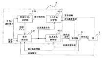
- FIG. 4 is a diagram showing a flow of heating control by the heating control unit 431, the hot water temperature control unit 432, the system identification unit 433, and the control gain determination unit 434 in the present embodiment.
- the system identification unit 433 calculates the thermal characteristics of the house 1 from the room temperature information acquired from the room temperature sensor 2 of the house 1 and the tapping temperature command from the heating control unit 431, and the control gain determination unit 434. Output to.
- the control gain determination unit 434 calculates a plurality of control gains in the heating control unit 431 based on the thermal characteristics of the house 1 calculated by the system identification unit 433.
- the heating control unit 431 generates a gain selection signal based on room temperature information and the like, and outputs the gain selection signal to the control gain determination unit 434.
- the control gain determination unit 434 determines the control gain according to the gain selection signal and outputs the control gain to the heating control unit 431.
- the heating control unit 431 generates a tapping temperature command from the control gain calculated by the control gain determining unit 434, the set temperature, and the room temperature information acquired from the room temperature sensor 2, and outputs the command to the tapping temperature control unit 432.
- the hot water temperature command is a target value of the temperature of the water flowing through the use-side flow path 50 on the outlet side of the refrigerant-water heat exchanger 35 (hot water temperature).
- the tapping temperature control unit 432 generates a heat supply command to the heat source unit 3 from the tapping temperature command acquired from the heating control unit 431 and the tapping temperature information acquired by the tapping temperature sensor 21 of the heat source unit 3.
- the heat supply command is a control target value in the heat source device 3.
- the heat source device control unit 37 of the heat source device 3 controls the operation capacity of the compressor 31 in accordance with the heat supply command from the hot water temperature control unit 432 and supplies heat to the house 1.
- the mode determination unit 435 determines a mode such as heating or hot water supply according to the input data from the input / output unit 41.
- the output data processing unit 436 processes output data for the input / output unit 41.
- s is a Laplace operator
- y is the output
- x is the state variable
- tau r is the time constant
- u is the operation amount of the thermal properties of the house 1.
- Ts is a sampling period
- z is a lead element
- x [k] is a discretized state variable
- x [k ⁇ 1] is a discretized state variable one sample before
- u [k ⁇ 1] is This is the operation amount one sample before.
- Equation (4) is data at a certain point, and the system identification unit 433 acquires the state variable x and the manipulated variable u at a plurality of points, the proportional coefficient K r of the thermal characteristics of the house 1, and the thermal characteristics of the house 1.
- the time constant ⁇ r of is calculated. For example, when the state variable x and the manipulated variable u are 4 points, the following equation (5) is obtained. When the left-side vector is ⁇ , the right-side matrix is ⁇ , and the right-side vector is ⁇ in the time series data, From (6), the proportional coefficient K r of the thermal characteristics of the house 1 and the time constant ⁇ r of the thermal characteristics of the house 1 are obtained by the least square method using the pseudo inverse matrix.
- the discretized state variable x [k] in equation (5), the discretized state variable x [k ⁇ 1] one sample before, and the subscript of the manipulated variable u [k ⁇ 1] are data It is a number.
- the resolution of the state variable x or the manipulated variable u is high, the accuracy of system identification improves as the number of data points increases.
- the accuracy or resolution of the microcomputer used in the control device 4 or the AD converter mounted on the control board on which the microcomputer is mounted is low, for example, the detection resolution at room temperature corresponding to the state variable x is about 0.1 ° C.
- the independent data group of Formula (4) may not be obtained.
- the sampling period T s fixed in Expression (5) is replaced with a change sampling period T sn (n is a data number) that is the time until the state variable changes, and the manipulated variable u is replaced with the integrated value u. It is replaced with n_sum (n is a data number), and the sampling period Ts for change determination is set to about 10 seconds or less.
- the roughness of the detection resolution can be compensated.
- equation (5) becomes equation (7).
- the control device 4 can determine the change in the room temperature even if the period of the wireless communication is 10 seconds or more. Accuracy can be improved.
- FIG. 5 is a flowchart showing a flow of system identification processing according to the present embodiment.
- FIG. 5 shows an example in which the value of x n [k] ⁇ x n [k ⁇ 1] is 0.5 and the thermal characteristics of the house 1 are calculated based on four points of time series data. Note that the value of x n [k] ⁇ x n [k ⁇ 1] and the number of time-series data are not limited to this.
- the state variable x and the operation amount u at the start of system identification are acquired as initial data and stored in the storage unit 42 (S1). And the heating control by the heating control part 431 is performed using the initial control gain memorize
- This initial control gain may be set in advance based on the data of the test equipment, or when building data such as the heat insulation or heat capacity of each house 1 is obtained, it may be set in advance with reference to the value. Good.
- system identification by the system identification unit 433 is performed while performing heating control with an initial control gain.
- the data here are a state variable x n used for calculating the thermal characteristics of the house 1, an integrated value un_sum of the manipulated variable u, and a change sampling period T sn . If four points of data have not been acquired (S3: NO), it is determined whether or not the room temperature has increased by 0.5 ° C. or more from the previously stored room temperature (S4). When the room temperature has not risen by 0.5 ° C. or more from the room temperature stored last time (S4: NO), 1 is added to the sample count cnt (S5), and the operation amount u is integrated (S6). Then, the process returns to step S2, and the subsequent processing is repeated.
- the state variable x n is a room temperature detected by the room temperature sensor 2
- the integrated value un_sum of the operation amount u is an integrated value of a tapping temperature command generated by the heating control unit 431.
- the heating control unit 431 generates a tapping temperature command using the set temperature, the room temperature, and the initial control gain.
- the change sampling cycle T sn is obtained from the following equation (8) using the sample count cnt and the sampling cycle T s .
- the sample count cnt is reset (S8), the process returns to step S2 and the subsequent processing is repeated.
- S3 YES
- the time constant ⁇ r of the thermal characteristics of the house 1 and the proportional coefficient K r are obtained based on the acquired data. Is calculated (S9).
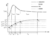
- FIG. 6 is a diagram illustrating an example of sampling in the system identification unit 433 according to the present embodiment.
- FIG. 6 shows a sampling example when the state variable x is room temperature and the manipulated variable u is a tapping temperature command.
- P 0 is a room temperature at the start of system identification, and a room temperature increased by 0.5 ° C. from this room temperature is defined as P 1 .
- the change sampling time T s1 and the integrated value u 1_sum of the tapping temperature command in this case are expressed as shown in FIG.
- P 1 corresponds to the room temperature of x 2 [k ⁇ 1] and x 1 [k]. Assuming that the room temperature further raised by 0.5 ° C.
- the manipulated variable u is set as a tapping temperature command in the heating control unit 431, but may be tapped temperature detected by the tapping temperature sensor 21.
- the tapping temperature it is necessary to take measures against noise in the hot water temperature information.
- the heating control unit 431 includes a PI controller (not shown), performs PI control based on the room temperature and the set temperature, and the design is pole-zero cancellation.
- the control gain determination unit 434 controls the control gain in the PI control of the heating control unit 431 based on the proportional coefficient K r of the thermal characteristics of the house 1 calculated by the system identification unit 433 and the time constant ⁇ r of the thermal characteristics of the house 1. Is calculated.
- the control gain determination unit 434 calculates a compressor ON gain when the compressor 31 of the heat source unit 3 is operating and a compressor OFF gain when the compressor 31 is stopped. To do.
- the compressor ON gain corresponds to the “first gain” of the present invention
- the compressor OFF gain corresponds to the “second gain” of the present invention.
- the PI controller of the heating control unit 431 designed in a continuous system is represented by the following formula (9).
- ⁇ c is a design time constant of the PI controller
- s is a Laplace operator.
- the PI controller is expressed by the following formula (10).
- the design time constant ⁇ c_ON of the PI controller gain when the compressor 31 is operating depends on the dead time determined by the total amount and flow rate of the hot water flowing through the use side flow path 50, but even if the dead time is long. About 10 minutes. Therefore, when setting the design time constant ⁇ c_ON so that the room temperature does not overshoot, ⁇ c_ON may be 2.6 times or more of the dead time. For example, if the dead time is 10 minutes, ⁇ c_ON is about 1600 seconds. Further, in the case of FIG. 6, the dead time is obtained by measuring the time when the room temperature starts to rise from the time when the tapping temperature command is raised.
- the design time constant ⁇ c_OFF of the PI controller gain when the compressor 31 is stopped is the time constant ⁇ r of the thermal characteristics of the house 1. If the time constant ⁇ r and proportional coefficient K r of the thermal characteristics of the house can be predicted from the thermal insulation at the time of designing the house 1 and the catalog data of the indoor unit 5, the control gain is designed using the predicted values. May be.
- the control gain determination unit 434 determines either the compressor ON gain or the compressor OFF gain calculated as described above based on the gain selection signal of the heating control unit 431, and outputs the determined gain to the heating control unit 431. .
- the heating control unit 431 determines which one of the compressor ON gain and the compressor OFF gain to use from room temperature information from the room temperature sensor 2 or the like. For example, if one or more of the deviation between the set temperature and room temperature is 0 or more, the tapping temperature command is greater than the lower limit value, or the value corresponding to the amount of heat is greater than the minimum heat value of the heat source unit 3, the compressor ON Select the gain. On the other hand, if the deviation between the set temperature and room temperature is less than 0, the hot water temperature command is the lower limit value, or the heat equivalent value is less than 0, or one or more of these are satisfied, the compressor OFF gain is selected To do. Then, this result is generated as a gain selection signal and output to the control gain determination unit 434.
- FIG. 7 is a block diagram of heating control unit 431 in the present embodiment.
- the heating control unit 431 performs control calculation for each control cycle Tc based on the room temperature deviation obtained by subtracting the room temperature information detected by the room temperature sensor 2 from the set temperature, and updates the tapping temperature command.
- Control period T c is either a sampling period T s and the equivalent, is an integer multiple of the sampling period T s.
- Proportional gain in K p is the input control gain determining unit 434 proportional gain K P_On or K P_OFF calculated in is the integral gain K I_ON or K I_off is input to the integral gain K i. Further, the heating control unit 431 determines whether or not the calculated hot water temperature command is within the upper and lower limiter, and the difference between the hot water temperature command before the limiter process and the hot water temperature command after the limiter process and the proportional gain Kp . An anti-reset windup process using the reciprocal is performed. By this process, even when the tapping temperature command reaches the upper and lower limit values, the tapping temperature command does not stick to the upper and lower limit values, but changes quickly, and an energy saving effect is obtained by suppressing room temperature overshoot.
- FIG. 8 is a flowchart showing the flow of the heating control process in the present embodiment.
- the control gain determination unit 434 uses the time constant ⁇ r of the thermal characteristics of the house 1 obtained by the system identification unit 433 and the proportional coefficient K r of the thermal characteristics of the house 1 to compress the compressor.
- An ON gain and a compressor OFF gain are calculated (S21).
- a gain selection signal is acquired from the heating control part 431 (S22), and it is judged based on the acquired gain selection signal whether the gain for compressor ON is selected (S23).
- the compressor ON gain is selected (S23: YES)
- the compressor ON gain is output to the heating control unit 431.
- the heating control calculation is performed by the heating control unit 431 using the compressor ON gain, and the tapping temperature command is updated (S24).
- the updated hot water temperature command is output to the hot water temperature control unit 432 (S25).
- the compressor ON gain is not selected (S23: NO)
- the compressor OFF gain is output to the heating control unit 431.
- the heating control calculation using the gain for compressor OFF is performed by the heating control part 431, and the tapping temperature command is updated (S26).
- the tapping temperature control unit 432 performs PI control for matching the tapping temperature command from the heating control unit 431 and tapping temperature information from the tapping temperature sensor 21 to generate a heat supply command to the heat source unit 3.
- the PI control equation is the same as equation (10).
- the control gain of the hot water temperature control unit 432 is calculated by performing system identification using the state variable x of equation (5) as the hot water temperature information and the operation amount u as the heat supply command.
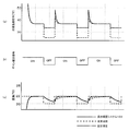
- FIG. 9 is a diagram illustrating an example of a simulation result in the hot water heating system 100 of the present embodiment.
- FIG. 9A shows the transition of the tapping temperature command
- FIG. 9B shows the gain selection signal
- FIG. 9C shows the transition of the room temperature.
- the set temperature at home (16 hours) is 22 ° C.
- the set temperature at absence (8 hours) is 20 ° C.
- the time constant ⁇ r of the thermal characteristics of the house 1 is 20000 seconds (about 5.6 hours)
- the proportionality coefficient K r of the thermal characteristics of the house 1 is 0.6
- the time constant ⁇ c_ON when the compressor is ON is 3600 seconds.
- a continuous line shows the tapping temperature command in the hot water heating system 100 of this Embodiment, and a broken line shows the tapping temperature command in a prior art.
- a continuous line shows the room temperature at the time of using the hot water heating system 100 of this Embodiment
- a broken line shows the room temperature in the case of using the hot water heating system of a prior art
- a dashed-dotted line is hot water The preset temperature in a heating system is shown.
- the gain selection signal is turned OFF (compressor OFF), and the control gain in the heating control unit 431 is compressed. Changed to machine OFF gain.
- the time constant in the heating control unit 431 becomes the time constant ⁇ r of the thermal characteristics of the house 1, and the value of the tapping temperature command when the set temperature is raised from 20 ° C. to 22 ° C. shows the room temperature response at the set temperature 20 ° C. The reflected value (about 33 ° C.) is obtained.
- the room temperature response to the set temperature of 22 ° C. is as designed.
- the room temperature response becomes slower than the design.
- the set temperature is particularly high. The effect of improving the followability can be obtained.
- the hot water temperature command is updated using the compressor OFF gain, so that when the operation of the compressor 31 is resumed, Control can be started with a hot water temperature command.
- the hot water temperature at the time of restarting the operation of the compressor 31 becomes continuous from the hot water temperature before the stop, and the state before the stop of the compressor 31 can be taken over, room temperature comfort is not impaired. Energy saving effect can be obtained.
- the thermal characteristics of the actual house 1 in the system identification unit 433 the thermal characteristics of the indoor unit 5 such as floor heating, radiator, fan coil unit and the like that are different in the hot water temperature zone to be used and the thermal characteristics of the house 1 are obtained. Even when different wooden, concrete and brick houses 1 are combined, the room temperature can be controlled comfortably.
- the system identification unit 433 calculates a proportional coefficient K r and the time constant tau r thermal properties of the house 1, the control gain determining unit 434 in the heating control section 431 constant tau r when the thermal properties of the house 1
- the tapping temperature command is lowered in accordance with the natural heat dissipation characteristics of the house 1.
- the heating control unit 431 uses the hot water temperature command generated using the set temperature, the room temperature information, and the initial control gain as an input variable, and uses the room temperature information of the house 1 as an output variable.
- the thermal characteristics of the house 1 including the delay of the tapping temperature control system can be calculated, and the accuracy of system identification is improved. As a result, the comfort of heating control is improved and room temperature overshoot is less likely to occur, so that energy savings can be improved.
- system identification unit 433 calculates the thermal characteristics of the house 1 based on a plurality of time series data having different sampling periods, so that the time until the change can be included in the time series data, and the room temperature measurement is performed. Even when the resolution is coarse, the roughness can be compensated by the time data. As a result, the accuracy of system identification can be improved.
- the hot water temperature control unit 432 by providing the hot water temperature control unit 432, fluctuations in heat supply from the heat source unit 3 can be suppressed by the hot water temperature control system, and the influence on the upper heating control system can be reduced.
- Embodiment 2 a second embodiment of the present invention will be described.
- the system identification is performed using the hot water temperature command from the heating control unit 431 as an input variable and the room temperature information from the room temperature sensor 2 as an output variable.
- the heating control unit 431 is used. Is different from the first embodiment in that the input temperature is a tapping temperature command from the A and a return temperature information from the return temperature sensor 22.
- the input temperature is a tapping temperature command from the A and a return temperature information from the return temperature sensor 22.
- the other structure of the hot water heating system 100 and each apparatus it is the same as that of Embodiment 1, and attaches
- FIG. 10 is a diagram illustrating a flow of heating control by the heating control unit 431, the tapping temperature control unit 432, the system identification unit 433, and the control gain determination unit 434 in the present embodiment.
- the system identification unit 433 uses the room temperature information acquired from the room temperature sensor 2 of the house 1, the hot water temperature command from the heating control unit 431, and the return temperature information from the return temperature sensor 22. 1 is calculated and output to the control gain determination unit 434. Specifically, the system identification unit 433 calculates the time constant ⁇ r and the proportional coefficient K r of the thermal characteristics of the house 1 using the difference between the tapping temperature command and the return temperature as the manipulated variable u.
- the control gain determination unit 434 uses the compressor ON gain and the compressor OFF gain in the heating control unit 431.
- the gain is calculated and output to the heating control unit 431 according to the gain selection signal.
- the heating control unit 431 generates a tapping temperature command from the control gain calculated by the control gain determining unit 434, the set temperature, and the room temperature information acquired from the room temperature sensor 2, and outputs it to the tapping temperature control unit 432.
- FIG. 11 is a block diagram of the heating control unit 431 in the present embodiment.
- the output of the PI control calculation of equation (10) is the difference between the tapping temperature command and the return temperature command.
- a value obtained by adding the return temperature information from the temperature sensor 22 to the output of the PI controller is used as the hot water temperature command before the limiter.
- heating control unit 431 inputs the tapping temperature command and return temperature generated using the set temperature, room temperature information, and initial control gain.
- the room temperature information of the house 1 as an output variable, it is possible to calculate the thermal characteristics of the house 1 including the delay of the tapping temperature control system and the heat release status of the indoor heat exchanger 51, and the accuracy of system identification Is improved, and the room temperature followability of the heating control is improved.
- comfort is improved and room temperature overshooting is less likely to occur due to improvement in room temperature follow-up, so that energy savings can also be improved.
- the thermal characteristics of the house 1 is a single-input single-output model as shown in the equation (1), whereas in the present embodiment, the thermal characteristics of the house 1 are converted to a multi-input single-output model. It differs from the first and second embodiments in that it is an output system model.
- selection of the control gain in the PI controller of the heating control unit 431 was performed according to ON / OFF of the compressor 31, but in this embodiment, the compressor 31 is turned on.
- the ON / OFF of the circulation pump 36 that circulates hot water in the indoor unit 5 is also considered. Note that components similar to those in the first embodiment are denoted by the same reference numerals as those in the first embodiment.
- FIG. 12 shows a thermal network model in the present embodiment.
- FIG. 12A is a thermal circuit network model to be controlled in the present embodiment
- FIG. 12B is a thermal circuit network model when there is an amount of heat supplied from the indoor unit 5
- FIG. c) is a thermal circuit network model when there is no amount of heat supplied from the indoor unit 5.
- the thermal characteristics of the house 1 are set as a single-input single-output system model of Expression (1), and system identification is performed while the indoor unit 5 supplies heat. Then, using the result obtained by system identification, the control gain in PI control of the heating control unit 431 is calculated by Expression (11) to Expression (14).
- control gains air conditioning ON gain and air conditioning OFF gain
- T o is the outside air temperature
- T z at room temperature Q idu supply heat of the indoor unit 5
- R all the thermal resistance of the house 1 [K / kW]
- C all Indicates the heat capacity [kJ / K] of house 1, respectively.
- FIG. 13 is a schematic configuration diagram of the hot water circulation circuit in the present embodiment.
- the hot water circulation circuit of the present embodiment is different from the hot water circulation circuit of the first embodiment shown in FIG.
- Other configurations of the hot water circulation circuit are the same as those in the first embodiment.
- the outside air temperature sensor 500 is provided in the heat source device 3.
- the present invention is not limited to this, and any structure that provides outside air temperature information to the control device 4 may be used.
- the outside temperature sensor 500 may be provided separately and connected to the input / output unit 41 of the control device 4.
- FIG. 14 is a functional block diagram of the control device 4 in the present embodiment.
- the present embodiment is different from the control device 4 according to the first embodiment shown in FIG. 3 in that the outside air temperature information is stored in the storage unit 42.
- Other configurations of the control device 4 are the same as those in the first embodiment.
- the outside air temperature information is stored in the storage unit 42 from the heat source device 3 via the input / output unit 41 of the control device 4 and is used for the processing of the control unit 43.
- the outside air temperature information may be obtained not only from the outside air temperature sensor 500 but also by converting weather forecast data in a form that can be taken into the control device 4.
- FIG. 15 is a diagram illustrating a flow of heating control by the heating control unit 431, the tapping temperature control unit 432, the system identification unit 433, and the control gain determination unit 434 in the present embodiment.
- the present embodiment is different from the heating control flow of the first embodiment shown in FIG. 4 in that the outside air temperature information is supplied from the heat source device 3 to the system identification unit 433. Other configurations in the flow of heating control are the same as those in the first embodiment.
- the outside air temperature information is used by the system identification unit 433 for system identification.
- FIG. 16 is an example of determining a gain selection signal in the present embodiment.
- the heating control unit 431 generates a gain selection signal based on ON / OFF of the compressor 31, but in this embodiment, the circulation pump 36 that circulates hot water through the indoor unit 5 is used.
- ON / OFF Specifically, as shown in FIG. 16, either the air conditioning ON gain or the air conditioning OFF gain is selected depending on ON / OFF of the circulation pump 36, that is, whether heat is supplied from the indoor unit 5.
- the air conditioning ON gain is selected depending on ON / OFF of the circulation pump 36, that is, whether heat is supplied from the indoor unit 5.
- the air conditioning OFF gain is selected. If the circulation pump 36 is ON even when the compressor 31 is OFF, the air conditioning ON gain is selected.
- the determination of the gain selection signal is not limited to the example of FIG. 16.
- the air conditioning ON gain may be selected.
- the case where heat is supplied when the circulation pump 36 of the indoor unit 5 is ON is “air conditioning ON”, and the case where the indoor unit 5 is not supplying heat while the circulation pump 36 is OFF (natural heat dissipation). Only state) is referred to as “air conditioning OFF”.
- the air conditioning ON gain corresponds to the “first gain” of the present invention
- the air conditioning OFF gain corresponds to the “second gain” of the present invention.
- the system identification target is a model of the formula (15), and system identification is performed separately when the air conditioning is on and when the air conditioning is off.
- Expression (15) is expressed using the proportionality coefficient K r of the thermal characteristics of the house 1 and the time constant ⁇ r of the thermal characteristics of the house 1 in Expression (1), the following Expression (16) is obtained.
- the system identification can be performed while suppressing the influence of the outside air temperature change by performing the system identification on a cloudy day in the daytime or at night.
- the system identification process at the time of air conditioning ON is the same as the content described in the first embodiment.
- FIG. 17 is a flowchart showing a flow of system identification processing (when air conditioning is OFF) in the present embodiment.
- the state variable x and the operation amount u at the start of system identification are acquired as initial data and stored in the storage unit 42 (S31).
- the heating control by the heating control part 431 is performed using the initial control gain memorize
- the hot water temperature command in the heating control unit 431 is updated, and the hot water temperature command to the hot water temperature control unit 432 is not updated.
- the data here are a state variable x n used for calculating the thermal characteristics of the house 1, an integrated value un_sum of the manipulated variable u, and a change sampling period T sn . If four points of data have not been acquired (S33: NO), it is determined whether the room temperature has decreased by 0.5 ° C. or more from the room temperature stored last time (S34). This is because the room temperature decreases when the air conditioner is OFF. If the room temperature has not dropped by 0.5 ° C. or more from the room temperature stored last time (S34: NO), 1 is added to the sample count cnt (S35), and the operation amount u is integrated (S36). Then, the process returns to step S32, and the subsequent processing is repeated.
- S34 room temperature stored last time
- the state variable x n is the room temperature detected by the room temperature sensor 2
- the integrated value un_sum of the operation amount u is the outside air temperature detected by the outside air temperature sensor 500.
- the change sampling period T sn is a value obtained by the above equation (8). Thereafter, the sample count cnt is reset (S38), the process returns to step S32, and the subsequent processing is repeated.
- the design time constant ⁇ c is the time constant ⁇ r of the thermal characteristics of the house 1 as in the first and second embodiments.
- FIG. 18 is a flowchart showing the flow of the heating control process in the present embodiment.
- the control gain determination unit 434 uses the time constant ⁇ r of the thermal characteristics of the house 1 obtained by the system identification unit 433 and the proportional coefficient K r of the thermal characteristics of the house 1 to turn on the air conditioning.
- the gain for air conditioning and the gain for air conditioning OFF are calculated separately when the air conditioning is on and when the air conditioning is off (S41).
- a gain selection signal is acquired from the heating control part 431 (S42), and it is judged whether the gain for an air conditioning ON is selected based on the acquired gain selection signal (S43).
- the heating control unit 431 generates a gain selection signal in consideration of not only ON / OFF of the compressor 31 but also ON / OFF of the circulation pump 36.
- the air conditioning ON gain is selected (S43: YES)
- the air conditioning ON gain is output to the heating control unit 431.
- the heating control calculation is performed by the heating control part 431 using the gain for air conditioning ON, and the tapping temperature command is updated (S44).
- the updated hot water temperature command is output to the hot water temperature control unit 432 (S45).
- the air conditioning ON gain is not selected (S43: NO)
- the air conditioning OFF gain is output to the heating control unit 431.
- the heating control calculation using the gain for air conditioning OFF is performed by the heating control part 431, and the tapping temperature command is updated (S46).
- the operation state on the use side flow path 50 side is also reflected, so that the gain selection is performed more accurately. I can do it.
- the control gain design of the PI controller is closer to the actual usage environment. Calculated by state. Thereby, the hot water temperature command at the time of air-conditioning ON resumption is set appropriately, room temperature controllability is improved, and it becomes comfortable.
- FIG. 19 shows the heating control by the heating control unit 431, the hot water temperature control unit 432, the system identification unit 433, and the control gain determination unit 434 when the return temperature information is used as in the second embodiment. It is a figure which shows the flow of. In the present embodiment, outside temperature information is added to Embodiment 2, and the outside temperature information is used by the system identification unit 433 as shown in FIG.
- Embodiment 4 FIG. Next, a fourth embodiment of the present invention will be described.
- the present embodiment is different from the third embodiment in that the thermal characteristics of the house 1 are different models when the air conditioning is on and when the air conditioning is off.
- the other configurations of the hot water heating system 100 and each device are the same as those in the third embodiment, and are denoted by the same reference numerals.
- the system identification target is represented by equation (19), and in this embodiment as well, the system identification is performed separately when the air conditioning is on and when the air conditioning is off.
- the system time constants are different between when the air conditioning is turned on and when the air conditioning is turned off, and a model is used in which the room temperature does not converge to the outside air temperature when the air conditioning is turned off.
- the reason why the room temperature does not converge to the outside temperature when the air conditioner is OFF is that there is heat from home appliances and certification in the house 1 and the influence of solar radiation.
- Equation (19) in order to take these into consideration with an inexpensive microcomputer, in Equation (19), it is assumed that other than the heat supply by air conditioning is proportional to the outside air temperature, and the PI controller air conditioning OFF gain and air conditioning ON gain As a model for design.
- K r_OFF is a proportional coefficient of the thermal characteristics of the house 1 when the air conditioner is OFF
- ⁇ r_OFF is a time constant of the thermal characteristics of the house 1 when the air conditioner is OFF.
- the present embodiment even when the room temperature does not converge to the outside air temperature when the air conditioner is turned off, it is possible to set a control gain according to the actual environment, and the hot water temperature when the air conditioner is resumed. The command is set appropriately, the room temperature controllability is improved, and it becomes comfortable.
- the hot water heating system 100 may have not only a heating function but also other functions such as a cooling function.
- the hot water heating system 100 of the present invention can be applied not only to the house 1 but also to various buildings such as buildings.
- the measurement point of room temperature is not limited to one place, You may control the whole building by making the average value or minimum value of several measurement points into a measurement point.
- the system identification unit 433 includes the room temperature information acquired from the room temperature sensor 2 of the house 1, the tapping temperature command from the heating control unit 431, the return temperature information from the return temperature sensor 22, and the flow rate detected by the flow sensor 23. From the above, the thermal characteristics of the house 1 may be calculated. Specifically, when the heat supply equivalent value obtained by multiplying the return temperature difference obtained by subtracting the return temperature information from the tapping temperature information and the flow rate is the operation amount u of the equation (5) or the equation (5), A constant ⁇ r and a proportional coefficient K r are calculated. Also in this case, the accuracy of system identification is improved, and the room temperature followability of heating control is improved.
Landscapes
- Engineering & Computer Science (AREA)
- Chemical & Material Sciences (AREA)
- Combustion & Propulsion (AREA)
- Mechanical Engineering (AREA)
- General Engineering & Computer Science (AREA)
- Physics & Mathematics (AREA)
- Thermal Sciences (AREA)
- Fuzzy Systems (AREA)
- Mathematical Physics (AREA)
- Signal Processing (AREA)
- Steam Or Hot-Water Central Heating Systems (AREA)
- Heat-Pump Type And Storage Water Heaters (AREA)
- Other Air-Conditioning Systems (AREA)
Abstract
温水暖房システムは、建物の室温情報を検出する室温センサと、温水を生成する熱源機と、熱源機によって生成される温水の熱を放出して建物を暖房する室内機と、熱源機を制御する制御装置と、を備える。また、制御装置は、建物の熱特性に基づいて第1ゲインおよび第2ゲインを算出する制御ゲイン決定部と、第1ゲインおよび第2ゲインを用いて、冷媒-水熱交換器の水の出口温度の目標値である出湯温度指令を更新する暖房制御部と、室内機が建物へ熱を供給する空調ONの場合に、暖房制御部で更新される出湯温度指令に基づいて熱源機への熱供給指令を行う出湯温度制御部と、を有する。さらに、第1ゲインは、空調ONの場合に所望の室温応答となるような出湯温度指令を得るように設計されるものであり、第2ゲインは、室内機が建物へ熱を供給しない空調OFFの場合の室温変化を反映した出湯温度指令を得るように設計されるものであり、暖房制御部は、空調ONの場合は、室温の設定温度と室温情報と第1ゲインとを用いて出湯温度指令を更新し、空調OFFの場合は、設定温度と室温情報と第2ゲインとを用いて出湯温度指令を更新する。
Description
本発明は、建物内の暖房を行う温水暖房システム、該温水暖房システムの制御装置および制御方法に関するものである。
従来、ヒートポンプを用いた熱源機で生じた熱により加熱した温水を循環して暖房を行う温水暖房システムが知られている。また、温水暖房システムの制御において、省エネなどの理由から、室温などに応じて熱源機の停止および駆動を繰り返すことが知られている。具体的には、設定温度が室温より低い場合、または必要な熱量が熱源機を運転した際の最低値を下回るような空調負荷が低い場合には、熱源機を停止する。そして、熱源機の停止後、時間の経過とともに外気の影響などで室温が下がり、室温が設定温度よりも低くなった場合などには、熱源機の運転を再開する。例えば、特許文献1には、往路側の温水温度を検出し、事前に設定された目標温度に応じてフィードバック制御を行う温水暖房装置が記載されている。特許文献1の温水暖房装置では、往路側の温水温度が所定の消火温度まで上昇した場合は、熱源機の運転が停止され、往路側の温水温度が目標温度よりも低い所定の再点火温度まで低下した場合は、熱源機の運転が再開される。
ラジエータまたは床暖房などの温水暖房装置における出湯温度を設定温度と一致するように制御する際、必要熱量が熱源機の最低発熱量以下となった場合には熱源機の運転を停止する必要があり、出湯温度が設定温度を下回った場合には、熱源機の運転を再開する必要がある。ここで、従来の温水暖房装置では、熱源機の運転を再開する際には、実際の建物の熱特性が考慮されていない予め設定された熱供給指令によって、熱源機が制御される。この場合、予め設定された熱供給指令が、建物に本来必要な熱量よりも過大であると、出湯温度が上限値を超えて再度停止することがあり、短時間で運転と停止が繰り返されることがある。その結果、アクチュエータの耐久性の低下と省エネ性が損なわれる可能性がある。また、予め設定された熱供給指令が、本来必要な熱量よりも少ない場合には、出湯温度が十分に上昇しないため、室温が上昇しにくくなり、快適性が損なわれてしまう。
また、省エネのために不在時または夜間に暖房の設定温度を下げ、熱源機による熱供給を停止させることがあるが、室温が設定温度より下がった場合、帰宅時または朝方に暖房の設定温度を上げる等して、熱源機が熱供給を再開する。このとき、予め設定された所定の温度の出湯温度指令にて熱供給が再開されると、熱供給の停止直前までに暖房制御によって調整されてきた出湯温度指令情報が生かせず、一からフィードバック制御を仕切り直すことになる。その結果、暖房制御が不連続となり、室温を安定させるために要する時間が長くなってしまう。特に高気密/高断熱の家において、室温が設定温度に下がりきる前に設定温度が上昇した場合には、暖房制御の不連続性により、室温が設定温度に達するまでに時間がかかり、快適性が損なわれてしまう。
本発明は、上記のような課題を解決するためになされたもので、快適性を損なうことなく省エネを実現する温水暖房システム、制御装置および制御方法を提供することを目的とする。
本発明に係る温水暖房システムは、建物の室温情報を検出する室温センサと、温水を生成する熱源機と、熱源機によって生成される温水の熱を放出して建物を暖房する室内機と、熱源機を制御する制御装置と、を備え、熱源機は、冷媒を圧縮する圧縮機と、冷媒と水との熱交換を行う冷媒-水熱交換器と、温水を冷媒-水熱交換器と室内機の間で循環させる循環ポンプとを有し、制御装置は、建物の熱特性に基づいて第1ゲインおよび第2ゲインを算出する制御ゲイン決定部と、第1ゲインおよび第2ゲインを用いて、冷媒-水熱交換器の水の出口温度の目標値である出湯温度指令を更新する暖房制御部と、室内機が建物へ熱を供給する空調ONの場合に、暖房制御部で更新される出湯温度指令に基づいて熱源機への熱供給指令を行う出湯温度制御部と、を有し、第1ゲインは、空調ONの場合に所望の室温応答となるような出湯温度指令を得るように設計されるものであり、第2ゲインは、室内機が建物へ熱を供給しない空調OFFの場合の室温変化を反映した出湯温度指令を得るように設計されるものであり、暖房制御部は、空調ONの場合は、室温の設定温度と室温情報と第1ゲインとを用いて出湯温度指令を更新し、空調OFFの場合は、設定温度と室温情報と第2ゲインとを用いて出湯温度指令を更新する。
本発明の温水暖房システムによれば、空調OFFの場合も、設定温度と室温情報と第2ゲインとを用いて出湯温度指令が更新される。これにより、更新された出湯温度指令に基づいて運転が再開され、空調OFFから空調ONまでの出湯温度を連続的とすることができる。そのため、空調OFF前の状態を引き継ぐことができ、室温快適性を損なわずに省エネ効果を得ることができる。
以下に、本発明における温水暖房システムの実施の形態を図面に基づいて詳細に説明する。
実施の形態1.
図1は、本発明の実施の形態1における温水暖房システム100の概略構成図である。温水暖房システム100は暖房対象の建物である家1の室温を測定する室温センサ2と、暖房に使用される温水を生成する熱源機3と、室温センサ2により検知された室温が設定温度と一致するように熱源機3に熱供給指令を与える制御装置4と、熱源機3から供給される温水の熱を室内に放出して暖房する室内機5とから構成される。
実施の形態1.
図1は、本発明の実施の形態1における温水暖房システム100の概略構成図である。温水暖房システム100は暖房対象の建物である家1の室温を測定する室温センサ2と、暖房に使用される温水を生成する熱源機3と、室温センサ2により検知された室温が設定温度と一致するように熱源機3に熱供給指令を与える制御装置4と、熱源機3から供給される温水の熱を室内に放出して暖房する室内機5とから構成される。
図2は、本実施の形態における温水循環回路の概略構成図である。温水循環回路は、ヒートポンプサイクルを有する熱源機3と、室内機5に設けられる室内熱交換器51とが接続されて構成される。図2に示すように、熱源機3は、圧縮機31と、室外熱交換器32と、ファン33と、冷媒流量調整装置34と、冷媒-水熱交換器35と、循環ポンプ36とを備える。さらに、熱源機3は、熱源機3の各部を制御する熱源機制御部37を備える。
図2に示すように、圧縮機31と、室外熱交換器32と、冷媒流量調整装置34と、冷媒-水熱交換器35とは、熱源側流路30によって直列に接続される。熱源側流路30内には、熱を搬送するための冷媒が循環される。また、冷媒-水熱交換器35と、室内熱交換器51と、循環ポンプ36とは、利用側流路50によって直列に接続される。利用側流路50内には、熱を搬送するための熱媒体として、水が循環される。圧縮機31は、吸入側から吸入された冷媒を圧縮し、高温高圧のガス冷媒として吐出側から吐出する。室外熱交換器32は、暖房運転時には冷媒の蒸発器として機能し、室外空気と冷媒との熱交換を行い、室外空気から熱を吸熱する。ファン33は、室外熱交換器32に送風し、室外熱交換器32における吸熱を調整する。冷媒流量調整装置34は、例えば電子膨張弁であり、冷媒-水熱交換器35を流れる冷媒の流量を調整する。
冷媒-水熱交換器35は、暖房運転時には冷媒の凝縮器として機能し、熱源側流路30を循環する冷媒と、利用側流路50を循環する水との熱交換を行う。これにより、互いに独立する熱源側流路30と利用側流路50の流路が熱的に接続される。なお、利用側流路50内を循環させる熱媒体として、水の替りに不凍液または水と不凍液の混合液等を用いてもよい。循環ポンプ36は、冷媒-水熱交換器35を介して温められた温水の流量を調整する。利用側流路50を循環する温水は、室内熱交換器51によって熱を放出し再び冷媒-水熱交換器35を介して温められる。
また、熱源機3は、利用側流路50において、冷媒-水熱交換器35の出口側に設けられ、出湯温度を検知する出湯温度センサ21と、冷媒-水熱交換器35の入口側に設けられ、室内熱交換器51を通過して循環してきた水の戻り温度を検知する戻り温度センサ22と、利用側流路50を循環する水の流量を検知する流量センサ23とを備える。これらのセンサによって検知された情報は、熱源機制御部37にアナログ通信またはディジタル通信により送信される。熱源機制御部37は、制御装置4からの熱供給指令および各センサからの情報に基づいて、圧縮機31の運転容量、ファン33の風量、冷媒流量調整装置34の開度、循環ポンプ36の流量などを制御する。
図3は、本実施の形態における制御装置4の機能ブロック図である。図3に示すように、制御装置4は、室温センサ2、熱源機3および室内機5と情報をやり取りする入出力部41と、各種情報およびプログラムを記憶する記憶部42と、各部の制御を行う制御部43とを備える。
入出力部41は、ディジタル入力部411と、AD変換部412と、シリアル通信部413と、表示部414と、を有する。ディジタル入力部411は、室内機5または熱源機3の運転情報、制御装置4のスイッチ情報、または図示しないフロースイッチなどをディジタル信号で受信する。AD変換部412は、室温センサ2、出湯温度センサ21、戻り温度センサ22からのアナログ情報をディジタル情報に変換する。シリアル通信部413は、室内機5または熱源機3と、シリアル通信で各種設定情報または各センサ情報をやり取りするためのインターフェースである。また、シリアル通信部413は、室内機5のリモコン(図示しない)などから無線通信で室温情報を受信してもよい。表示部414は、設定温度、現在の室温、または出湯温度などの情報を液晶画面に表示する。
記憶部42は、不揮発性メモリなどで構成される。記憶部42には、システム同定完了前の初期制御ゲインなどの初期設定値、入出力部41からの各種センサ情報、システム同定部433で算出された家1の熱特性、制御ゲイン決定部434で設計された制御ゲイン、熱源機3への熱供給指令データ、および入出力部41を介して入力される入力データなどが記憶される。
制御部43は、マイクロコンピュータまたはDSP(Digital Signal Processor)などで構成される。制御部43は、暖房制御部431と、出湯温度制御部432と、システム同定部433と、制御ゲイン決定部434と、モード判定部435と、出力データ処理部436と、を有する。上記各部は、ソフトウェアで実現される機能部として制御部43が備えるCPU(図示せず)によって、記憶部42などの記録媒体に記憶されるプログラムを実行することで実現される。または、上記各部は、ASIC(Application Specific IC)、FPGA(Field Programmable Gate Array)またはPLD(Programmable Logic Device)などの電子回路で実現されてもよい。
図4は、本実施の形態における暖房制御部431、出湯温度制御部432、システム同定部433、および制御ゲイン決定部434による暖房制御の流れを示す図である。図4に示すように、システム同定部433は、家1の室温センサ2から取得した室温情報と暖房制御部431からの出湯温度指令から、家1の熱特性を算出し、制御ゲイン決定部434に出力する。制御ゲイン決定部434は、システム同定部433によって算出された家1の熱特性に基づいて、暖房制御部431における複数の制御ゲインを算出する。暖房制御部431は、室温情報などに基づいてゲイン選択信号を生成し、制御ゲイン決定部434に出力する。制御ゲイン決定部434は、ゲイン選択信号に応じて制御ゲインを決定し、暖房制御部431に出力する。
暖房制御部431は、制御ゲイン決定部434で算出された制御ゲインと、設定温度と、室温センサ2から取得した室温情報とから出湯温度指令を生成し、出湯温度制御部432に出力する。出湯温度指令は、冷媒-水熱交換器35の出口側における利用側流路50を流れる水の温度(出湯温度)の目標値である。出湯温度制御部432は、暖房制御部431から取得した出湯温度指令と熱源機3の出湯温度センサ21で取得した出湯温度情報とから熱源機3への熱供給指令を生成する。熱供給指令は、熱源機3における制御目標値である。熱源機3の熱源機制御部37は、出湯温度制御部432からの熱供給指令に応じて、圧縮機31の運転容量などを制御し、家1への熱供給を実施する。
図3に戻って、モード判定部435は、入出力部41からの入力データに従い、暖房または給湯などのモードの判定を行う。また、出力データ処理部436は、入出力部41用の出力データを処理する。
次に、システム同定部433による家1の熱特性の算出について説明する。家1の熱特性を一次遅れ系の伝達関数と仮定すると、熱量から室温までの伝達関数は下記の式(1)で表される。

ここで、sはラプラス演算子、yは出力、xは状態変数、Krは家1の熱特性の比例係数、τrは家1の熱特性の時定数、uは操作量である。式(1)を下記の式(2)の後退差分で離散化すると下記の式(3)が得られる。


ここで、Tsはサンプリング周期、zは進み要素、x[k]は離散化された状態変数、x[k-1]は1サンプル前の離散化された状態変数、u[k-1]は1サンプル前の操作量である。式(3)を変形すると下記の式(4)となる。

式(4)は、ある一点のデータであり、システム同定部433は、複数点の状態変数xおよび操作量uを取得し、家1の熱特性の比例係数Kr、および家1の熱特性の時定数τrを算出する。例えば、状態変数xおよび操作量uを4点とった場合は、下記の式(5)のようになり、時系列データで左辺ベクトルをα、右辺行列をβ、右辺ベクトルをγとすると、式(6)から疑似逆行列を用いた最小二乗法により、家1の熱特性の比例係数Krと家1の熱特性の時定数τrが求まる。


ここで式(5)の離散化された状態変数x[k]、1サンプル前の離散化された状態変数x[k-1]、および操作量u[k-1]の添え字は、データナンバーである。状態変数xまたは操作量uの分解能が高い場合には、データ点数が多い程、システム同定の精度は向上する。しかしながら、制御装置4に用いられるマイコンまたは、マイコンを搭載した制御基板に搭載されたAD変換器の精度または分解能が低い場合、例えば状態変数xに相当する室温の検出分解能が0.1℃程度の場合、独立した式(4)のデータ群が得られないことがある。この場合は、式(5)で固定としていたサンプリング周期Tsを、状態変数が変化するまでの時間である変化サンプリング周期Tsn(nはデータナンバー)に置き換えるとともに、操作量uを積算値un_sum(nはデータナンバー)に置き換え、変化判定用のサンプリング周期Tsを10秒程度以下とする。これにより、検出分解能の粗さを補うことができる。また、xn[k]-xn[k-1]の値も予め設定しておくことで、制御装置4に安価なマイコンを搭載した場合でも、暖房制御しながら家1の熱特性を計算することができる。この場合、式(5)は式(7)となる。

また、室温センサ2からの室温情報を有線でなく、リモコンなどの無線機器から無線通信で受信する場合には、電池寿命の問題から無線通信の周期が長くなる。この場合は、室温情報とともに、経過時間に関する情報を受信することで、無線通信の周期が10秒以上であったとしても、制御装置4にて室温の変化を判定することができ、システム同定の精度を向上させることができる。
図5は、本実施の形態のシステム同定処理の流れを示すフローチャートである。図5は、xn[k]-xn[k-1]の値を0.5とし、4点の時系列データに基づいて家1の熱特性を算出する場合の例である。なお、xn[k]-xn[k-1]の値、および時系列データの数については、これに限定されるものではない。図5に示すように、本処理では、まず、システム同定開始時の状態変数x、操作量uが初回データとして取得され、記憶部42に保存される(S1)。そして、記憶部42に記憶される初期制御ゲインを用いて暖房制御部431による暖房制御が行われる(S2)。この初期制御ゲインは試験設備のデータを基に予め設定してもよいし、個々の家1の断熱性または熱容量などの建築データが得られる場合には、その値を参考に予め設定してもよい。本実施の形態では初期制御ゲインでの暖房制御を行いながらシステム同定部433によるシステム同定が行われる。
次に、4点のデータが取得されたか否かが判断される(S3)。ここでいうデータは、家1の熱特性を算出するために用いられる状態変数xn、操作量uの積算値un_sum、および変化サンプリング周期Tsnである。そして、4点のデータが取得されていない場合(S3:NO)、前回保存した室温から室温が0.5℃以上上昇しているか否かが判断される(S4)。そして、前回保存した室温から室温が0.5℃以上上昇していない場合(S4:NO)、サンプルカウントcntに1が加算され(S5)、操作量uの積算が行われる(S6)。そして、ステップS2に戻り、以降の処理が繰り返される。
一方、前回保存した室温から室温が0.5℃以上上昇している場合(S4:YES)、状態変数xnと、操作量uの積算値un_sumと、変化サンプリング周期Tsnとが保存される(S7)。状態変数xnは、室温センサ2によって検知される室温であり、操作量uの積算値un_sumは、暖房制御部431によって生成される出湯温度指令の積算値である。ここでは、暖房制御部431は、設定温度と、室温と、初期制御ゲインとを用いて出湯温度指令を生成する。また、変化サンプリング周期Tsnは、サンプルカウントcntとサンプリング周期Tsを用いて、下記の式(8)から求められる。

その後、サンプルカウントcntがリセットされ(S8)、ステップS2に戻って以降の処理が繰り返される。そして、システム同定開始時の初回データとは異なる4点のデータが取得された場合(S3:YES)、取得されたデータに基づいて、家1の熱特性の時定数τrと比例係数Krが算出される(S9)。
図6は、本実施の形態のシステム同定部433におけるサンプリングの例を示す図である。図6は、状態変数xを室温、操作量uを出湯温度指令とした場合のサンプリング例を示す。P0は、システム同定開始時の室温であり、この室温を基準に室温が0.5℃上昇した室温をP1とする。この場合の変化サンプリング時間Ts1、出湯温度指令の積算値u1_sumは、図6のように表される。また、P1は、x2[k-1]、x1[k]の室温に相当する。室温P1からさらに0.5℃上昇した室温をP2とすると、P1からP2に変化するまでの変化サンプリング時間Ts2と出湯温度指令の積算値u2_sumは、図6のように表される。P3およびP4においても同様である。なお、本実施の形態では操作量uを暖房制御部431における出湯温度指令としたが、出湯温度センサ21で検知される出湯温度としてもよい。ただし、出湯温度を用いる場合には、出湯温度情報のノイズ対策が必要である。また、出湯温度を用いる場合には、出湯温度制御部432の制御系の応答が考慮されなくなるため、出湯温度指令を操作量uとして用いることが望ましい。
次に、制御ゲイン決定部434における制御ゲインの決定について説明する。以下では、暖房制御部431が、PI制御器(図示せず)を有し、室温と設定温度とに基づいてPI制御を行うこととし、その設計を極零相殺とした場合について説明する。制御ゲイン決定部434は、システム同定部433によって算出された家1の熱特性の比例係数Krおよび家1の熱特性の時定数τrに基づいて、暖房制御部431のPI制御における制御ゲインを算出する。また、制御ゲイン決定部434は、熱源機3の圧縮機31が動作している場合における圧縮機ON用ゲインと、圧縮機31が停止している場合における圧縮機OFF用ゲインと、をそれぞれ算出する。なお、圧縮機ON用ゲインが本発明の「第1ゲイン」に相当し、圧縮機OFF用ゲインが本発明の「第2ゲイン」に相当する。
具体的には、連続系で設計された暖房制御部431のPI制御器は下記の式(9)で表される。ここで、τcはPI制御器の設計時定数であり、sはラプラス演算子である。

また、比例ゲインKp、積分ゲインKi、ラプラス演算子sを用いると、PI制御器は下記の式(10)で表される。

また、圧縮機31が動作している場合のPI制御器ゲインの設計時定数をτc_ONとすると、圧縮機ON用ゲインである比例ゲインKp_ONおよび積分ゲインKi_ONは、下記の式(11)および式(12)で求められる。


また、圧縮機31が停止している場合のPI制御器ゲインの設計時定数をτc_OFFとすると、圧縮機OFF用ゲインである比例ゲインKP_OFFおよび積分ゲインKi_OFFは、それぞれ下記の式(13)および式(14)で求められる。


ここで、圧縮機31が動作している場合のPI制御器ゲインの設計時定数τc_ONは、利用側流路50を流れる温水の総量と流量で決まるむだ時間によるが、むだ時間は長くても10分程度である。そのため、室温がオーバーシュートしないように設計時定数τc_ONを設定する場合には、τc_ONをむだ時間の2.6倍以上とすればよい。例えば、むだ時間を10分とすると、τc_ONは、約1600秒となる。また、むだ時間は、図6の場合には出湯温度指令が上昇した時間から室温が上昇し始める時間を計ることで求まる。また、圧縮機31が停止している場合のPI制御器ゲインの設計時定数τc_OFFは、家1の熱特性の時定数τrとする。なお、家1の設計時の断熱性および室内機5のカタログデータから、家の熱特性の時定数τrと比例係数Krが予想できる場合は、予想した値を用いて制御ゲインを設計してもよい。制御ゲイン決定部434は、以上のように算出した圧縮機ON用ゲインと圧縮機OFF用ゲインのどちらかを、暖房制御部431のゲイン選択信号に基づいて決定し、暖房制御部431へ出力する。
次に、暖房制御部431の暖房制御について説明する。暖房制御部431は、室温センサ2からの室温情報などから、圧縮機ON用ゲインと圧縮機OFF用ゲインの何れを使用するかを決定する。例えば、設定温度と室温との偏差が0以上、出湯温度指令が下限値より大きい、熱量相当値が熱源機3の最低発熱量より大きい、の何れかまたは複数が成立した場合、圧縮機ON用ゲインを選択する。一方、設定温度と室温の偏差が0より小さい、出湯温度指令が下限値となった場合、熱量相当値が0より小さい、の何れかまたは複数が成立した場合に、圧縮機OFF用ゲインを選択する。そして、この結果をゲイン選択信号として生成し、制御ゲイン決定部434に出力する。
また、暖房制御部431は、制御ゲイン決定部434にて決定された圧縮機ON用ゲインまたは圧縮機OFF用ゲインに基づいて、出湯温度指令を更新する。図7は本実施の形態における暖房制御部431のブロック線図である。暖房制御部431は、設定温度から室温センサ2で検知される室温情報を差し引いた室温偏差に基づいて、制御周期Tc毎に制御演算を行い、出湯温度指令を更新する。制御周期Tcはサンプリング周期Tsと同値であるか、サンプリング周期Tsの整数倍である。
比例ゲインKpには制御ゲイン決定部434で算出された比例ゲインKp_ONまたはKp_OFFが入力され、積分ゲインKiには積分ゲインKi_ONまたはKi_OFFが入力される。また、暖房制御部431は、演算結果の出湯温度指令が上下限リミッタ内に入っているかを判定し、リミッタ処理前の出湯温度指令とリミッタ処理後の出湯温度指令の差と比例ゲインKpの逆数を用いたアンチリセットワインドアップ処理を行う。この処理により、出湯温度指令が上下限値に達した場合でも出湯温度指令が上下限値に張り付かず、速やかに変化し、室温のオーバーシュートを抑制することで省エネ効果が得られる。
図8は、本実施の形態における暖房制御処理の流れを示すフローチャートである。本処理では、まず、制御ゲイン決定部434にて、システム同定部433で得られた家1の熱特性の時定数τrと、家1の熱特性の比例係数Krを用いて、圧縮機ON用ゲインと、圧縮機OFF用ゲインとが算出される(S21)。そして、暖房制御部431からゲイン選択信号が取得され(S22)、取得したゲイン選択信号に基づいて、圧縮機ON用ゲインを選択するか否かが判断される(S23)。
ここで、圧縮機ON用ゲインを選択する場合(S23:YES)、圧縮機ON用ゲインが暖房制御部431に出力される。そして、暖房制御部431によって、圧縮機ON用ゲインを用いて暖房制御演算が行われ、出湯温度指令が更新される(S24)。その後、更新された出湯温度指令が出湯温度制御部432へ出力される(S25)。また、圧縮機ON用ゲインを選択しない場合(S23:NO)、すなわち圧縮機OFF用ゲインを選択する場合、圧縮機OFF用ゲインが暖房制御部431に出力される。そして、暖房制御部431によって、圧縮機OFF用ゲインを用いた暖房制御演算が行われ、出湯温度指令が更新される(S26)。この場合は、圧縮機31が停止しているため、出湯温度制御部432への出湯温度指令の出力は行われず、暖房制御部431内の出湯温度指令のみが更新される。そして、室温情報などに応じて暖房制御部431から制御ゲイン決定部434にゲイン選択信号が出力され、ステップS22からステップS26までの処理が繰り返される。
次に、出湯温度制御部432の熱供給指令の生成について説明する。出湯温度制御部432は、暖房制御部431からの出湯温度指令と出湯温度センサ21からの出湯温度情報を一致させるためのPI制御を行って、熱源機3への熱供給指令を生成する。PI制御の式は式(10)と同様である。出湯温度制御部432の制御ゲインは、式(5)の状態変数xを出湯温度情報、操作量uを熱供給指令としてシステム同定を行って算出される。
図9は、本実施の形態の温水暖房システム100におけるシミュレーション結果の一例を示す図である。図9(a)は出湯温度指令の推移を示し、図9(b)はゲイン選択信号を示し、図9(c)は室温の推移を示す。シミュレーション条件として、在宅時(16時間)の設定温度を22℃、不在時(8時間)の設定温度を20℃とする。また、家1の熱特性の時定数τrは20000秒(約5.6時間)、家1の熱特性の比例係数Krは0.6、圧縮機ON時の時定数τc_ONは3600秒とする。図9(a)において、実線は本実施の形態の温水暖房システム100における出湯温度指令を示し、破線は従来技術における出湯温度指令を示す。また、図9(c)において、実線は本実施の形態の温水暖房システム100を用いた場合の室温を示し、破線は従来技術の温水暖房システムを用いた場合における室温を示し、一点鎖線は温水暖房システムにおける設定温度を示す。
図9(a)に示すように、本実施の形態では、不在時に設定温度が20℃に変更された場合、ゲイン選択信号がOFF(圧縮機OFF)となり、暖房制御部431における制御ゲインが圧縮機OFF用ゲインに変更される。これにより、暖房制御部431における時定数が家1の熱特性の時定数τrとなり、設定温度を20℃から22℃に上げた時の出湯温度指令の値が設定温度20℃の室温応答を反映した値(約33℃)となる。その結果、設定温度22℃への室温応答が設計応答通りとなる。これに対し、従来技術では、圧縮機31が停止した場合の出湯制御指令値として、予め設定された所定温度(25℃)が用いられるため、室温応答が設計よりも遅くなってしまう。このように、本実施の形態では、設定温度の下げ指令から上げ指令の設定時間に対して、家1の熱特性の時定数が長い、いわゆる高断熱/高気密性の住宅において、特に設定温度追従性の改善効果が得られる。
以上のように、本実施の形態によれば、圧縮機31の停止時にも、圧縮機OFF用ゲインを用いて出湯温度指令を更新することで、圧縮機31の動作を再開する際に、適切な出湯温度指令で制御を開始することができる。また、圧縮機31の動作再開時の出湯温度が停止前の出湯温度から連続的なものになり、圧縮機31の停止前の状態を引き継ぐことが可能となるため、室温快適性を損なわずに省エネ効果を得ることができる。また、システム同定部433にて、実際の家1の熱特性を算出することにより、使用する温水温度帯が異なる床暖房、ラジエータ、ファンコイルユニット等の室内機5と、家1の熱特性が異なる木造、コンクリート造、レンガ造等の家1が組み合わされた場合でも室温を快適に制御することができる。
また、システム同定部433において、家1の熱特性の比例係数Krおよび時定数τrを算出し、制御ゲイン決定部434は、家1の熱特性の時定数τrを暖房制御部431における設計時定数として、圧縮機OFF用ゲインを算出することで、出湯温度指令が家1の自然放熱特性に合わせて低下していくことになる。これにより、圧縮機31の動作再開時の出湯温度が室温変化状況を反映したものとなり、室温制御特性を改善することができる。
また、システム同定部433において、暖房制御部431が、設定温度と、室温情報と、初期制御ゲインとを用いて生成した出湯温度指令を入力変数とし、家1の室温情報を出力変数として、家1の熱特性を算出することで、出湯温度制御系の遅れを含めた家1の熱特性を算出することができ、システム同定の精度が向上する。その結果、暖房制御の快適性が向上し、室温のオーバーシュートが生じにくくなるため、省エネ性の改善を図ることができる。
また、システム同定部433において、サンプリング周期が異なる複数の時系列データに基づいて、家1の熱特性を算出することで、変化するまでの時間を時系列データに含めることができ、室温の測定分解能が粗い場合でも時間データによりその粗さを補うことができる。その結果、システム同定の精度を向上させることができる。
さらに、出湯温度制御部432を備えることにより、熱源機3からの熱供給変動を出湯温度制御系で抑制し、上位の暖房制御系への影響を小さくすることができる。
実施の形態2.
次に、本発明の実施の形態2について説明する。上記実施の形態1では、暖房制御部431からの出湯温度指令を入力変数とし、室温センサ2からの室温情報を出力変数としてシステム同定を行うのに対し、実施の形態2では、暖房制御部431からの出湯温度指令および戻り温度センサ22からの戻り温度情報を入力変数とする点において、実施の形態1と相違する。温水暖房システム100および各装置のその他の構成については、実施の形態1と同様であり、同一の符号を付する。
次に、本発明の実施の形態2について説明する。上記実施の形態1では、暖房制御部431からの出湯温度指令を入力変数とし、室温センサ2からの室温情報を出力変数としてシステム同定を行うのに対し、実施の形態2では、暖房制御部431からの出湯温度指令および戻り温度センサ22からの戻り温度情報を入力変数とする点において、実施の形態1と相違する。温水暖房システム100および各装置のその他の構成については、実施の形態1と同様であり、同一の符号を付する。
図10は、本実施の形態における暖房制御部431、出湯温度制御部432、システム同定部433、および制御ゲイン決定部434による暖房制御の流れを示す図である。図10に示すように、システム同定部433は、家1の室温センサ2から取得した室温情報と、暖房制御部431からの出湯温度指令と、戻り温度センサ22からの戻り温度情報とから、家1の熱特性を算出し、制御ゲイン決定部434に出力する。具体的には、システム同定部433は、出湯温度指令と戻り温度の差を操作量uとして、家1の熱特性の時定数τrと比例係数Krとを算出する。
制御ゲイン決定部434は、システム同定部433によって算出された家1の熱特性の時定数τrと比例係数Krとに基づいて、暖房制御部431における圧縮機ON用ゲインと圧縮機OFF用ゲインを算出し、ゲイン選択信号に応じて暖房制御部431に出力する。暖房制御部431は、制御ゲイン決定部434で算出された制御ゲインと、設定温度と、室温センサ2から取得した室温情報とから出湯温度指令を生成し、出湯温度制御部432に出力する。
図11は本実施の形態における暖房制御部431のブロック線図である。本実施の形態では、式(10)のPI制御演算の出力は、出湯温度指令と戻り温度指令の差となっている。これを出湯温度指令に変換するため、図11に示すように、PI制御器の出力に戻り温度センサ22からの戻り温度情報を加算した値をリミッタ前の出湯温度指令とする。
以上のように、本実施の形態によれば、システム同定部433において、暖房制御部431が、設定温度と、室温情報と、初期制御ゲインとを用いて生成した出湯温度指令および戻り温度を入力変数とし、家1の室温情報を出力変数とすることで、出湯温度制御系の遅れと室内熱交換器51の放熱状況を含めた家1の熱特性を算出することができ、システム同定の精度が向上し、暖房制御の室温追従性が改善される。これにより、快適性が向上するとともに、室温追従性の改善により室温のオーバーシュートが生じにくくなるため、省エネ性の改善も実現することができる。
実施の形態3.
次に、本発明の実施の形態3について説明する。上記実施の形態1および2では、家1の熱特性を式(1)のように単入力単出力系のモデルとするのに対し、本実施の形態では、家1の熱特性を多入力単出力系のモデルとする点において、実施の形態1および2と相違する。また、実施の形態1および2では、圧縮機31のON/OFFに応じて暖房制御部431のPI制御器における制御ゲインの選択を行っていたが、本実施の形態では、圧縮機31のON/OFFに加え、室内機5に温水を循環させる循環ポンプ36のON/OFFも考慮する点において相違する。なお、実施の形態1と同様の構成については、実施の形態1と同一の符号を付す。
次に、本発明の実施の形態3について説明する。上記実施の形態1および2では、家1の熱特性を式(1)のように単入力単出力系のモデルとするのに対し、本実施の形態では、家1の熱特性を多入力単出力系のモデルとする点において、実施の形態1および2と相違する。また、実施の形態1および2では、圧縮機31のON/OFFに応じて暖房制御部431のPI制御器における制御ゲインの選択を行っていたが、本実施の形態では、圧縮機31のON/OFFに加え、室内機5に温水を循環させる循環ポンプ36のON/OFFも考慮する点において相違する。なお、実施の形態1と同様の構成については、実施の形態1と同一の符号を付す。
図12は、本実施の形態における熱回路網モデルである。図12(a)は、本実施の形態の制御対象となる熱回路網モデルであり、図12(b)は室内機5からの供給熱量がある場合の熱回路網モデルであり、図12(c)は室内機5からの供給熱量がない場合の熱回路網モデルである。上記の実施の形態1および2では、家1の熱特性を式(1)の単入力単出力系モデルとし、室内機5が熱供給している間にシステム同定を行っている。そして、システム同定で得られた結果を用いて、暖房制御部431のPI制御における制御ゲインを式(11)~式(14)で算出している。これに対し本実施の形態では、図12(a)の熱回路網モデルを制御対象としてPI制御における制御ゲイン(空調ON用ゲインおよび空調OFF用ゲイン)を設計する。
図12(a)~図12(c)において、Toは外気温、Tzは室温、Qiduは室内機5の供給熱量、Rallは家1の熱抵抗[K/kW]、Callは家1の熱容量[kJ/K]をそれぞれ示す。重ね合わせの理を適用し、図12(b)に示す室内機5からの供給熱量がある場合の熱回路網モデルと、図12(c)に示す供給熱量がない場合の熱回路網モデルとを用い、室内機供給熱から室温、外気温から室温までのそれぞれの伝達関数を足し合わせると、図12(a)の熱回路網モデルは下記の式(15)で表される。

図13は本実施の形態における温水循環回路の概略構成図である。本実施の形態の温水循環回路は、外気温度センサ500を備える点において図2に示す実施の形態1の温水循環回路と相違する。温水循環回路のその他の構成は、実施の形態1と同様である。なお、図13では、熱源機3に外気温度センサ500が設けられているが、これに限定されるものではなく、制御装置4に外気温度情報を与える構成であればよい。例えば、室温センサ2のように外気温度センサ500を別体で設け、制御装置4の入出力部41に接続してもよい。
図14は本実施の形態における制御装置4の機能ブロック図である。本実施の形態では、記憶部42に外気温度情報が記憶される点において、図3に示す実施の形態1の制御装置4と相違する。制御装置4のその他の構成は実施の形態1と同様である。外気温度情報は、熱源機3から制御装置4の入出力部41を介し記憶部42に保存され、制御部43の処理に使用される。なお、外気温情報は、外気温度センサ500から取得するだけでなく、天気予報のデータを制御装置4に取り込める形で変換して得るようにしてもよい。
図15は本実施の形態における暖房制御部431、出湯温度制御部432、システム同定部433および制御ゲイン決定部434による暖房制御の流れを示す図である。本実施の形態では、熱源機3からシステム同定部433に外気温度情報が供給される点において、図4に示す実施の形態1の暖房制御の流れと相違する。暖房制御の流れにおけるその他の構成は、実施の形態1と同様である。外気温度情報は、システム同定部433においてシステム同定に用いられる。
図16は、本実施の形態におけるゲイン選択信号の決定例である。実施の形態1および2では、暖房制御部431は、圧縮機31のON/OFFに基づいてゲイン選択信号を生成していたが、本実施の形態では室内機5に温水を循環させる循環ポンプ36のON/OFFも加えて考慮する。具体的には図16のように循環ポンプ36のON/OFF、すなわち室内機5による熱供給の有無で、空調ON用ゲインまたは空調OFF用ゲインの何れかを選択する。図16の例では、圧縮機31がONでも循環ポンプ36がOFFの場合は、空調OFF用ゲインを選択する。また、圧縮機31がOFFでも循環ポンプ36がONの場合は、空調ON用ゲインを選択する。なお、ゲイン選択信号の決定は、図16の例に限定されるものではなく、例えば、圧縮機31がONで、循環ポンプ36がOFFの場合は、通常は短時間しか起こり得ない状態であるので、空調ON用ゲインを選択してもよい。以降の説明において、室内機5の循環ポンプ36がONの状態で熱供給している場合を「空調ON」、循環ポンプ36がOFFの状態で室内機5が熱供給していない場合(自然放熱のみの状態)を「空調OFF」と称する。また、空調ON用ゲインが本発明の「第1ゲイン」に相当し、空調OFF用ゲインが本発明の「第2ゲイン」に相当する。
次に、本実施の形態のシステム同定部433による家1の熱特性の算出について説明する。本実施の形態では、システム同定の対象を式(15)のモデルとし、空調ON時と空調OFF時に分けて、システム同定を行う。式(15)を、式(1)の家1の熱特性の比例係数Krと、家1の熱特性の時定数τrを用いて表現すると下記の式(16)となる。

空調ON時には、日中の場合は曇りの日、または夜間にシステム同定を行うことによって外気温度変化による影響を抑えてシステム同定を行うことができる。空調ON時のシステム同定処理は、実施の形態1に記載の内容と同様である。
空調OFF時には、式(16)の右辺第1項のQiduが0となるため、外気温度から室温までの伝達関数(右辺第2項)を求めることができる。このとき、右辺第2項の伝達関数の状態変数の初期値を、空調OFF直前の室温とする。この初期値は、離散化方式によって異なるが、室温に比例する値である。
図17は本実施の形態におけるシステム同定処理(空調OFF時)の流れを示すフローチャートである。本処理では、まず、システム同定開始時の状態変数x、操作量uが初回データとして取得され、記憶部42に保存される(S31)。そして、記憶部42に記憶される初期制御ゲインを用いて暖房制御部431による暖房制御が行われる(S32)。ここで、空調OFFの場合、暖房制御において、暖房制御部431内部での出湯温度指令が更新され、出湯温度制御部432への出湯温度指令の更新は行わない。
次に、4点のデータが取得されたか否かが判断される(S33)。ここでいうデータは、家1の熱特性を算出するために用いられる状態変数xn、操作量uの積算値un_sum、および変化サンプリング周期Tsnである。そして、4点のデータが取得されていない場合(S33:NO)、前回保存した室温から室温が0.5℃以上低下しているか否かが判断される(S34)。空調OFF時には室温が低下するためである。そして、前回保存した室温から室温が0.5℃以上低下していない場合(S34:NO)、サンプルカウントcntに1が加算され(S35)、操作量uの積算が行われる(S36)。そして、ステップS32に戻り、以降の処理が繰り返される。
一方、前回保存した室温から室温が0.5℃以上低下している場合(S34:YES)、状態変数xnと、操作量uの積算値un_sumと、変化サンプリング周期Tsnとが保存される(S37)。状態変数xnは、室温センサ2によって検知される室温であり、操作量uの積算値un_sumは、外気温度センサ500によって検知される外気温度である。変化サンプリング周期Tsnは、上記の式(8)で求められる値である。その後、サンプルカウントcntがリセットされ(S38)、ステップS32に戻って以降の処理が繰り返される。そして、システム同定開始時の初回データとは異なる4点のデータが取得された場合(S33:YES)、取得されたデータに基づいて、家1の熱特性の時定数τrと比例係数Krが算出される(S39)。
そして、空調OFF時のPI制御器の制御ゲインである空調OFF用ゲインが式(17)および式(18)で求められる。設計時定数τcは実施の形態1および2と同様に家1の熱特性の時定数τrとする。


図18は本実施の形態における暖房制御処理の流れを示すフローチャートである。本処理では、まず、制御ゲイン決定部434にて、システム同定部433で得られた家1の熱特性の時定数τrと、家1の熱特性の比例係数Krを用いて、空調ON用ゲインおよび空調OFF用ゲインが空調ON時と空調OFF時に分けて算出される(S41)。そして、暖房制御部431からゲイン選択信号が取得され(S42)、取得したゲイン選択信号に基づいて、空調ON用ゲインを選択するか否かが判断される(S43)。なお、暖房制御部431は、圧縮機31のON/OFFだけでなく、循環ポンプ36のON/OFFを考慮して、ゲイン選択信号を生成する。
ここで、空調ON用ゲインを選択する場合(S43:YES)、空調ON用ゲインが暖房制御部431に出力される。そして、暖房制御部431によって、空調ON用ゲインを用いて暖房制御演算が行われ、出湯温度指令が更新される(S44)。その後、更新された出湯温度指令が出湯温度制御部432へ出力される(S45)。また、空調ON用ゲインを選択しない場合(S43:NO)、すなわち空調OFF用ゲインを選択する場合、空調OFF用ゲインが暖房制御部431に出力される。そして、暖房制御部431によって、空調OFF用ゲインを用いた暖房制御演算が行われ、出湯温度指令が更新される(S46)。この場合は、空調OFFとなっているため、出湯温度制御部432への出湯温度指令の出力は行われず、暖房制御部431内の出湯温度指令のみが更新される。そして、室温情報などに応じて暖房制御部431から制御ゲイン決定部434にゲイン選択信号が出力され、ステップS42からステップS46までの処理が繰り返される。
以上のように本実施の形態によれば、熱源機3の熱源側流路30側の運転状況に加え、利用側流路50側の運転状況も反映されるため、より正確にゲイン選択を実施できることができる。また、式(16)で表される外気温度の影響を考慮したモデルを用い、空調ON時と空調OFF時にそれぞれシステム同定を行うことで、PI制御器の制御ゲイン設計がより実使用環境に近い状態で算出される。これにより、空調ON再開時の出湯温度指令が適切に設定され、室温制御性が改善されて快適となる。
また、図19は本実施の形態において、実施の形態2のように戻り温度情報を用いた場合の暖房制御部431、出湯温度制御部432、システム同定部433および制御ゲイン決定部434による暖房制御の流れを示す図である。本実施の形態では、実施の形態2に対して外気温度情報が追加されており、外気温度情報は、図15のようにシステム同定部433で用いられる。
実施の形態4.
次に、本発明の実施の形態4について説明する。本実施の形態では、家1の熱特性を、空調ON時と空調OFF時とで異なるモデルとする点において、実施の形態3と相違する。温水暖房システム100および各装置のその他の構成については実施の形態3と同様であり、同一の符号を付する。
次に、本発明の実施の形態4について説明する。本実施の形態では、家1の熱特性を、空調ON時と空調OFF時とで異なるモデルとする点において、実施の形態3と相違する。温水暖房システム100および各装置のその他の構成については実施の形態3と同様であり、同一の符号を付する。
本実施の形態のシステム同定部433による家1の熱特性の算出について説明する。システム同定の対象を式(19)とし、本実施の形態でも実施の形態3と同様、空調ON時とOFF時に分けてシステム同定を行う。本実施の形態では、空調ON時と空調OFF時で系の時定数が異なることを想定し、空調OFF時に室温が外気温度に収束しない場合を想定したモデルが用いられる。空調OFF時に室温が外気温度に収束しない原因は、家1の中にある家電製品や証明等の熱があること、および日射の影響がある。また、空調や日射等によって家具、壁、床、天井などが蓄熱し、空調OFF後に室温が下がり始めると室内の空気と熱交換することがある。本実施の形態では、安価なマイコンでこれらを考慮するために、式(19)において、空調による熱供給以外を外気温度に比例するものとし、PI制御器の空調OFF用ゲインおよび空調ON用ゲインの設計用のモデルとしている。

ここでKr_OFFは空調OFF時の家1の熱特性の比例係数であり、τr_OFFは空調OFF時の家1の熱特性の時定数である。式(19)のモデルを用いてシステム同定した場合の、空調ON時のPI制御ゲインは実施の形態1の式(11)および式(12)を用いて求められる。また、空調OFF時のPI制御ゲインは、空調OFF時の家1の熱特性の比例係数Kr_OFFと、時定数τr_OFFと、空調OFF時の制御設計時定数τc_OFFとを用いて下記の式(20)および式(21)で求められる。


以上のように本実施の形態によれば、空調OFF時に室温が外気温度に収束しない場合であっても、実環境に合わせた制御ゲインを設定することが可能となり、空調ON再開時の出湯温度指令を適切に設定し、室温制御性が改善され快適となる。
以上が本発明の実施の形態の説明であるが、本発明は、上記の実施の形態の構成に限定されるものではなく、その技術的思想の範囲内で様々な変形または組み合わせが可能である。例えば、温水暖房システム100は、暖房機能だけでなく、冷房機能などのその他の機能を備えるものであってもよい。また、本発明の温水暖房システム100は、家1だけでなく、ビルなどの様々な建物にも適用することができる。また、室温の測定点は1箇所に限定されるものではなく、複数の測定点の平均値または最低値を測定点として建物全体を制御してもよい。
さらに、システム同定部433は、家1の室温センサ2から取得した室温情報と、暖房制御部431からの出湯温度指令と、戻り温度センサ22からの戻り温度情報と、流量センサ23で検知した流量とから、家1の熱特性を算出してもよい。具体的には、出湯温度情報から戻り温度情報を引き算した戻り温度差に流量を掛け算した熱供給相当値を式(5)または式(5)の操作量uとして、家1の熱特性の時定数τrと比例係数Krとを算出する。この場合も、システム同定の精度が向上し、暖房制御の室温追従性が改善される。
1 家、2 室温センサ、3 熱源機、4 制御装置、5 室内機、21 出湯温度センサ、22 戻り温度センサ、23 流量センサ、30 熱源側流路、31 圧縮機、32 室外熱交換器、33 ファン、34 冷媒流量調整装置、35 水熱交換器、36 循環ポンプ、37 熱源機制御部、41 入出力部、42 記憶部、43 制御部、50 利用側流路、51 室内熱交換器、100 温水暖房システム、411 ディジタル入力部、412 AD変換部、413 シリアル通信部、414 表示部、431 暖房制御部、432 出湯温度制御部、433 システム同定部、434 制御ゲイン決定部、435 モード判定部、436 出力データ処理部、500 外気温度センサ。
Claims (11)
- 建物の室温情報を検出する室温センサと、
温水を生成する熱源機と、
前記熱源機によって生成される温水の熱を放出して前記建物を暖房する室内機と、
前記熱源機を制御する制御装置と、
を備え、
前記熱源機は、
冷媒を圧縮する圧縮機と、
前記冷媒と水との熱交換を行う冷媒-水熱交換器と、
前記温水を前記冷媒-水熱交換器と前記室内機の間で循環させる循環ポンプとを有し、
前記制御装置は、
前記建物の熱特性に基づいて第1ゲインおよび第2ゲインを算出する制御ゲイン決定部と、
前記第1ゲインおよび前記第2ゲインを用いて、前記冷媒-水熱交換器の水の出口温度の目標値である出湯温度指令を更新する暖房制御部と、
前記室内機が前記建物へ熱を供給する空調ONの場合に、前記暖房制御部で更新される前記出湯温度指令に基づいて前記熱源機への熱供給指令を行う出湯温度制御部と、
を有し、
前記第1ゲインは、前記空調ONの場合に所望の室温応答となるような前記出湯温度指令を得るように設計されるものであり、
前記第2ゲインは、前記室内機が前記建物へ熱を供給しない空調OFFの場合の室温変化を反映した前記出湯温度指令を得るように設計されるものであり、
前記暖房制御部は、前記空調ONの場合は、室温の設定温度と前記室温情報と前記第1ゲインとを用いて前記出湯温度指令を更新し、前記空調OFFの場合は、前記設定温度と前記室温情報と前記第2ゲインとを用いて前記出湯温度指令を更新する温水暖房システム。 - 前記制御装置は、さらに前記建物の熱特性を算出するシステム同定部を備え、
前記システム同定部は、前記建物の熱特性の比例係数および時定数を算出するものであり、
前記制御ゲイン決定部は、前記建物の熱特性の時定数を、前記暖房制御部における設計時定数として、前記第2ゲインを算出することを特徴とする請求項1に記載の温水暖房システム。 - 前記制御ゲイン決定部は、前記熱源機によって生成される温水の総量と流量に応じたむだ時間から、前記暖房制御部における設計時定数を求め、前記第1ゲインを算出する請求項2に記載の温水暖房システム。
- 外気温度を検出する外気温度センサをさらに備え、
前記システム同定部は、前記空調ONの場合と前記空調OFFの場合に分けてシステム同定を行い、前記空調ONの場合のシステム同定には、前記室温情報を少なくとも用いて前記建物の熱特性を算出し、前記空調OFFの場合のシステム同定には、前記外気温度センサによって検出される外気温度を用いて、前記建物の熱特性を算出する請求項2または3に記載の温水暖房システム。 - 前記システム同定部は、前記暖房制御部が、前記室温の設定温度と、前記室温情報と、予め設定された初期制御ゲインとを用いて生成した出湯温度指令を入力変数とし、前記室温情報を出力変数として、前記建物の熱特性を算出する請求項2~4の何れか一項に記載の温水暖房システム。
- 前記熱源機は、前記室内機を通過し、前記冷媒-水熱交換器へ戻る水の戻り温度を検知する戻り温度センサをさらに備え、
前記システム同定部は、前記暖房制御部が、前記室温の設定温度と、前記室温情報と、予め設定された初期制御ゲインとを用いて生成した出湯温度指令および前記戻り温度を入力変数とし、前記室温情報を出力変数として、前記建物の熱特性を算出する請求項2~4の何れか一項に記載の温水暖房システム。 - 前記システム同定部は、サンプリング周期が異なる複数の時系列データに基づいて、前記建物の熱特性を算出する請求項2~6の何れか一項に記載の温水暖房システム。
- 前記室温情報は、室温と、経過時間とを含む請求項1~7の何れか一項に記載の温水暖房システム。
- 前記暖房制御部は、前記出湯温度指令に上下限値を設け、アンチリセットワインドアップ処理機能を備える請求項1~8の何れか一項に記載の温水暖房システム。
- 温水を生成する熱源機を備える温水暖房システムの制御装置であって、
暖房対象である建物の熱特性に基づいて、第1ゲインおよび第2ゲインを算出する制御ゲイン決定部と、
前記第1ゲインおよび前記第2ゲインを用いて、前記冷媒-水熱交換器の水の出口温度の目標値である出湯温度指令を更新する暖房制御部と、
前記室内機が前記建物へ熱を供給する空調ONの場合に、前記暖房制御部で更新される前記出湯温度指令に基づいて前記熱源機への熱供給指令を行う出湯温度制御部と、
を有し、
前記第1ゲインは、前記空調ONの場合に所望の室温応答となるような前記出湯温度指令を得るように設計されるものであり、
前記第2ゲインは、前記室内機が前記建物へ熱を供給しない空調OFFの場合の室温変化を反映した前記出湯温度指令を得るように設計されるものであり、
前記暖房制御部は、前記空調ONの場合は、室温の設定温度と前記室温情報と前記第1ゲインとを用いて前記出湯温度指令を更新し、前記空調OFFの場合は、前記設定温度と前記室温情報と前記第2ゲインとを用いて前記出湯温度指令を更新する制御装置。 - 温水を生成する熱源機を備える温水暖房システムの制御方法であって、
暖房対象である建物の熱特性に基づいて、第1ゲインおよび第2ゲインを算出する工程と、
前記第1ゲインおよび前記第2ゲインを用いて、前記冷媒-水熱交換器の水の出口温度の目標値である出湯温度指令を更新する工程と、
前記室内機が前記建物へ熱を供給する空調ONの場合に、前記更新される前記出湯温度指令に基づいて前記熱源機への熱供給指令を行う工程と、
を含み、
前記第1ゲインは、前記空調ONの場合に所望の室温応答となるような前記出湯温度指令を得るように設計されるものであり、
前記第2ゲインは、前記室内機が前記建物へ熱を供給しない空調OFFの場合の室温変化を反映した前記出湯温度指令を得るように設計されるものであり、
前記出湯温度指令を更新する工程は、前記空調ONの場合は、室温の設定温度と前記室温情報と前記第1ゲインとを用いて前記出湯温度指令を更新し、前記空調OFFの場合は、前記設定温度と前記室温情報と前記第2ゲインとを用いて前記出湯温度指令を更新することを含む制御方法。
Priority Applications (2)
| Application Number | Priority Date | Filing Date | Title |
|---|---|---|---|
| EP16802836.3A EP3306204B1 (en) | 2015-06-03 | 2016-01-21 | Hot-water heating system, control device, and control method |
| JP2017521706A JP6516838B2 (ja) | 2015-06-03 | 2016-01-21 | 温水暖房システム、制御装置および制御方法 |
Applications Claiming Priority (2)
| Application Number | Priority Date | Filing Date | Title |
|---|---|---|---|
| JP2015-113425 | 2015-06-03 | ||
| JP2015113425 | 2015-06-03 |
Publications (1)
| Publication Number | Publication Date |
|---|---|
| WO2016194397A1 true WO2016194397A1 (ja) | 2016-12-08 |
Family
ID=57440405
Family Applications (1)
| Application Number | Title | Priority Date | Filing Date |
|---|---|---|---|
| PCT/JP2016/051650 Ceased WO2016194397A1 (ja) | 2015-06-03 | 2016-01-21 | 温水暖房システム、制御装置および制御方法 |
Country Status (3)
| Country | Link |
|---|---|
| EP (1) | EP3306204B1 (ja) |
| JP (1) | JP6516838B2 (ja) |
| WO (1) | WO2016194397A1 (ja) |
Cited By (6)
| Publication number | Priority date | Publication date | Assignee | Title |
|---|---|---|---|---|
| CN114110933A (zh) * | 2021-10-29 | 2022-03-01 | 珠海格力电器股份有限公司 | 空气源热泵机组系统的控制方法和空气源热泵机组系统 |
| CN115031319A (zh) * | 2022-07-29 | 2022-09-09 | 郑州轻工业大学 | 一种利用自然能源的供水空调系统及控制方法 |
| US11754330B2 (en) | 2019-03-11 | 2023-09-12 | Mitsubishi Electric Corporation | Refrigeration cycle apparatus |
| JP2024022102A (ja) * | 2022-08-05 | 2024-02-16 | 三菱電機ビルソリューションズ株式会社 | 空調制御システムおよび制御方法 |
| KR20240084117A (ko) * | 2022-12-06 | 2024-06-13 | 린나이코리아 주식회사 | 실내 단열 상태에 따른 난방기기 난방 공급 열량 제어방법 |
| WO2025069831A1 (ja) * | 2023-09-25 | 2025-04-03 | 三菱重工サーマルシステムズ株式会社 | 制御装置、制御方法、およびプログラム |
Families Citing this family (1)
| Publication number | Priority date | Publication date | Assignee | Title |
|---|---|---|---|---|
| CN111207481A (zh) * | 2020-01-14 | 2020-05-29 | 珠海格力电器股份有限公司 | 一种水多联系统压缩机升降频控制方法、存储介质及空调 |
Citations (3)
| Publication number | Priority date | Publication date | Assignee | Title |
|---|---|---|---|---|
| JPS58106346A (ja) * | 1981-12-18 | 1983-06-24 | Yamatake Honeywell Co Ltd | 最適始動制御機能付端末制御器 |
| JPS63113244A (ja) * | 1986-10-29 | 1988-05-18 | Sanyo Electric Co Ltd | 空気調和機 |
| JP2014190600A (ja) * | 2013-03-27 | 2014-10-06 | Panasonic Corp | 空気調和装置 |
Family Cites Families (6)
| Publication number | Priority date | Publication date | Assignee | Title |
|---|---|---|---|---|
| US4784212A (en) * | 1986-11-21 | 1988-11-15 | Transmet Engineering, Inc. | Building perimeter thermal energy control system |
| CA2064122A1 (en) * | 1991-06-11 | 1992-12-12 | Darryl G. Hurmi | Apparatus for controlling unit ventilators |
| US6264111B1 (en) * | 1993-06-16 | 2001-07-24 | Siemens Building Technologies, Inc. | Proportional-integral-derivative controller having adaptive control capability |
| JP5657110B2 (ja) * | 2011-05-31 | 2015-01-21 | 三菱電機株式会社 | 温度調節システム及び空気調和システム |
| JP2013217604A (ja) * | 2012-04-11 | 2013-10-24 | Rinnai Corp | 温水暖房装置 |
| GB2520293B (en) * | 2013-11-14 | 2018-02-07 | Passivsystems Ltd | Improvements in and relating to temperature controlled systems |
-
2016
- 2016-01-21 EP EP16802836.3A patent/EP3306204B1/en active Active
- 2016-01-21 WO PCT/JP2016/051650 patent/WO2016194397A1/ja not_active Ceased
- 2016-01-21 JP JP2017521706A patent/JP6516838B2/ja active Active
Patent Citations (3)
| Publication number | Priority date | Publication date | Assignee | Title |
|---|---|---|---|---|
| JPS58106346A (ja) * | 1981-12-18 | 1983-06-24 | Yamatake Honeywell Co Ltd | 最適始動制御機能付端末制御器 |
| JPS63113244A (ja) * | 1986-10-29 | 1988-05-18 | Sanyo Electric Co Ltd | 空気調和機 |
| JP2014190600A (ja) * | 2013-03-27 | 2014-10-06 | Panasonic Corp | 空気調和装置 |
Non-Patent Citations (1)
| Title |
|---|
| See also references of EP3306204A4 * |
Cited By (10)
| Publication number | Priority date | Publication date | Assignee | Title |
|---|---|---|---|---|
| US11754330B2 (en) | 2019-03-11 | 2023-09-12 | Mitsubishi Electric Corporation | Refrigeration cycle apparatus |
| CN114110933A (zh) * | 2021-10-29 | 2022-03-01 | 珠海格力电器股份有限公司 | 空气源热泵机组系统的控制方法和空气源热泵机组系统 |
| CN114110933B (zh) * | 2021-10-29 | 2023-08-01 | 珠海格力电器股份有限公司 | 空气源热泵机组系统的控制方法和空气源热泵机组系统 |
| CN115031319A (zh) * | 2022-07-29 | 2022-09-09 | 郑州轻工业大学 | 一种利用自然能源的供水空调系统及控制方法 |
| CN115031319B (zh) * | 2022-07-29 | 2024-02-02 | 郑州轻工业大学 | 一种利用自然能源的供水空调系统的控制方法 |
| JP2024022102A (ja) * | 2022-08-05 | 2024-02-16 | 三菱電機ビルソリューションズ株式会社 | 空調制御システムおよび制御方法 |
| JP7734635B2 (ja) | 2022-08-05 | 2025-09-05 | 三菱電機ビルソリューションズ株式会社 | 空調制御システムおよび制御方法 |
| KR20240084117A (ko) * | 2022-12-06 | 2024-06-13 | 린나이코리아 주식회사 | 실내 단열 상태에 따른 난방기기 난방 공급 열량 제어방법 |
| KR102834059B1 (ko) | 2022-12-06 | 2025-07-17 | 린나이코리아 주식회사 | 실내 단열 상태에 따른 난방기기 난방 공급 열량 제어방법 |
| WO2025069831A1 (ja) * | 2023-09-25 | 2025-04-03 | 三菱重工サーマルシステムズ株式会社 | 制御装置、制御方法、およびプログラム |
Also Published As
| Publication number | Publication date |
|---|---|
| JPWO2016194397A1 (ja) | 2017-10-19 |
| EP3306204A4 (en) | 2019-01-30 |
| JP6516838B2 (ja) | 2019-05-22 |
| EP3306204B1 (en) | 2021-07-07 |
| EP3306204A1 (en) | 2018-04-11 |
Similar Documents
| Publication | Publication Date | Title |
|---|---|---|
| JP6516838B2 (ja) | 温水暖房システム、制御装置および制御方法 | |
| US8670871B2 (en) | Load processing balance setting apparatus | |
| CN105143780B (zh) | 空调系统控制装置 | |
| CN113366266B (zh) | 空调管理装置、空调管理系统、空调管理方法以及程序 | |
| JP7050760B2 (ja) | 空調装置、制御装置、空調方法及びプログラム | |
| JP2010249333A (ja) | 運転制御情報生成装置及び運転制御情報生成プログラム及び記録媒体及び運転制御情報生成方法 | |
| US10865997B2 (en) | Zone control with modulating boiler | |
| JP5951142B1 (ja) | 空調システム制御装置 | |
| WO2022044325A1 (ja) | 換気報知装置および換気報知プログラム | |
| JPWO2016194190A1 (ja) | ヒートポンプ利用システムの制御装置及びそれを備えたヒートポンプ利用システム | |
| JPS629137A (ja) | 空気調和機 | |
| KR101652247B1 (ko) | 공기조화기의 외기냉방 운전방법 | |
| CN108954716B (zh) | 空调器的控制方法、空调器和计算机可读存储介质 | |
| Gao et al. | Space temperature control of a GSHP-integrated air-conditioning system | |
| KR101843088B1 (ko) | 부하량에 따른 능동제어 기반의 지열시스템 및 이의 제어방법 | |
| US11525595B2 (en) | System for determining operation condition of precooling operation/preheating operation of air conditioner | |
| JP3518353B2 (ja) | ヒートポンプ式暖房装置 | |
| CN114623562A (zh) | 空气调节设备及其控制方法和控制装置 | |
| US20260085850A1 (en) | Air-conditioning system, control method, and recording medium | |
| JP2017067321A (ja) | ヒートポンプ制御装置、ヒートポンプ式暖房システムの温水供給ユニット、ヒートポンプ式暖房システム、及びヒートポンプ制御装置によって実行される方法 | |
| WO2025058856A1 (en) | Heat pump systems utilizing model predictive control algorithms | |
| JP2017072298A (ja) | 空気調和機 | |
| WO2020240659A1 (ja) | 制御装置、空気環境調整システム、空気環境調整方法、プログラム、及び記録媒体 | |
| CN118076840A (zh) | 空调控制装置、空调控制系统和空调控制方法 | |
| KR102573043B1 (ko) | 공간의 온도 변화에 기반하여 공조 부하를 예측하는 방법 및 이를 구현하는 공기조화기 |
Legal Events
| Date | Code | Title | Description |
|---|---|---|---|
| 121 | Ep: the epo has been informed by wipo that ep was designated in this application |
Ref document number: 16802836 Country of ref document: EP Kind code of ref document: A1 |
|
| ENP | Entry into the national phase |
Ref document number: 2017521706 Country of ref document: JP Kind code of ref document: A |
|
| NENP | Non-entry into the national phase |
Ref country code: DE |
|
| WWE | Wipo information: entry into national phase |
Ref document number: 2016802836 Country of ref document: EP |