WO2016194710A1 - 配管 - Google Patents
配管 Download PDFInfo
- Publication number
- WO2016194710A1 WO2016194710A1 PCT/JP2016/065335 JP2016065335W WO2016194710A1 WO 2016194710 A1 WO2016194710 A1 WO 2016194710A1 JP 2016065335 W JP2016065335 W JP 2016065335W WO 2016194710 A1 WO2016194710 A1 WO 2016194710A1
- Authority
- WO
- WIPO (PCT)
- Prior art keywords
- slurry
- pipe
- layer
- material layer
- piping
- Prior art date
- Legal status (The legal status is an assumption and is not a legal conclusion. Google has not performed a legal analysis and makes no representation as to the accuracy of the status listed.)
- Ceased
Links
Images

Classifications
-
- F—MECHANICAL ENGINEERING; LIGHTING; HEATING; WEAPONS; BLASTING
- F16—ENGINEERING ELEMENTS AND UNITS; GENERAL MEASURES FOR PRODUCING AND MAINTAINING EFFECTIVE FUNCTIONING OF MACHINES OR INSTALLATIONS; THERMAL INSULATION IN GENERAL
- F16L—PIPES; JOINTS OR FITTINGS FOR PIPES; SUPPORTS FOR PIPES, CABLES OR PROTECTIVE TUBING; MEANS FOR THERMAL INSULATION IN GENERAL
- F16L57/00—Protection of pipes or objects of similar shape against external or internal damage or wear
- F16L57/06—Protection of pipes or objects of similar shape against external or internal damage or wear against wear
-
- F—MECHANICAL ENGINEERING; LIGHTING; HEATING; WEAPONS; BLASTING
- F16—ENGINEERING ELEMENTS AND UNITS; GENERAL MEASURES FOR PRODUCING AND MAINTAINING EFFECTIVE FUNCTIONING OF MACHINES OR INSTALLATIONS; THERMAL INSULATION IN GENERAL
- F16L—PIPES; JOINTS OR FITTINGS FOR PIPES; SUPPORTS FOR PIPES, CABLES OR PROTECTIVE TUBING; MEANS FOR THERMAL INSULATION IN GENERAL
- F16L58/00—Protection of pipes or pipe fittings against corrosion or incrustation
- F16L58/02—Protection of pipes or pipe fittings against corrosion or incrustation by means of internal or external coatings
- F16L58/04—Coatings characterised by the materials used
- F16L58/14—Coatings characterised by the materials used by ceramic or vitreous materials
-
- F—MECHANICAL ENGINEERING; LIGHTING; HEATING; WEAPONS; BLASTING
- F16—ENGINEERING ELEMENTS AND UNITS; GENERAL MEASURES FOR PRODUCING AND MAINTAINING EFFECTIVE FUNCTIONING OF MACHINES OR INSTALLATIONS; THERMAL INSULATION IN GENERAL
- F16L—PIPES; JOINTS OR FITTINGS FOR PIPES; SUPPORTS FOR PIPES, CABLES OR PROTECTIVE TUBING; MEANS FOR THERMAL INSULATION IN GENERAL
- F16L9/00—Rigid pipes
- F16L9/14—Compound tubes, i.e. made of materials not wholly covered by any one of the preceding groups
-
- C—CHEMISTRY; METALLURGY
- C22—METALLURGY; FERROUS OR NON-FERROUS ALLOYS; TREATMENT OF ALLOYS OR NON-FERROUS METALS
- C22B—PRODUCTION AND REFINING OF METALS; PRETREATMENT OF RAW MATERIALS
- C22B23/00—Obtaining nickel or cobalt
- C22B23/04—Obtaining nickel or cobalt by wet processes
- C22B23/0407—Leaching processes
- C22B23/0415—Leaching processes with acids or salt solutions except ammonium salts solutions
- C22B23/043—Sulfurated acids or salts thereof
-
- F—MECHANICAL ENGINEERING; LIGHTING; HEATING; WEAPONS; BLASTING
- F16—ENGINEERING ELEMENTS AND UNITS; GENERAL MEASURES FOR PRODUCING AND MAINTAINING EFFECTIVE FUNCTIONING OF MACHINES OR INSTALLATIONS; THERMAL INSULATION IN GENERAL
- F16L—PIPES; JOINTS OR FITTINGS FOR PIPES; SUPPORTS FOR PIPES, CABLES OR PROTECTIVE TUBING; MEANS FOR THERMAL INSULATION IN GENERAL
- F16L23/00—Flanged joints
- F16L23/02—Flanged joints the flanges being connected by members tensioned axially
- F16L23/024—Flanged joints the flanges being connected by members tensioned axially characterised by how the flanges are joined to, or form an extension of, the pipes
Definitions
- the present invention relates to piping, and more particularly to a piping for sending a slurry and steam containing the slurry.
- HPAL High Pressure Acid Leach
- the nickel oxide ore was first classified and obtained by classification.
- a nickel oxide ore having a predetermined size is repulped into an ore slurry (hereinafter, also simply referred to as “slurry”), and the slurry is heated and pressurized stepwise and transferred to an autoclave.
- an acid such as sulfuric acid is added, and nickel or the like is leached from the nickel oxide ore slurry.
- the leached slurry is cooled and stepped down in stages and sent to the next step.
- the process of raising the temperature and increasing the pressure of the slurry as described above is a process using high-temperature waste steam generated in the HPAL process.
- the slurry to be treated is charged into a pressure vessel (hereinafter referred to as “heater tank”) by a centrifugal pump, heated by the steam blown into the heater tank, and transferred to the next heater tank.
- the temperature is raised to a desired temperature.
- the outer diameter of the suction pipe of the centrifugal pump is larger than the outer diameter of the discharge pipe. Therefore, in order to arrange the centrifugal pumps of the same type in series, pipes having different pipe diameters at one end and pipe diameters at the other end, so-called different diameter pipes, are used for connection between the centrifugal pumps to be connected in series.
- waste steam from a decompression tank provided in the next step of the autoclave is used, and the slurry is made acidic by acid such as sulfuric acid contained in the waste steam. Therefore, there is a problem that not only wear due to transfer of the slurry at high pressure but also corrosion due to transfer of the high temperature and acidic slurry proceeds.
- waste steam used in the process of raising the temperature and increasing the pressure of the slurry is sent from the decompression tank to the heater tank using piping, but the waste steam that has passed through the autoclave is used.
- Acid steam or steam containing an acidic slurry is used. Therefore, similar to the problem that occurs when the slurry is transferred, the piping from the decompression tank to the heater tank is rapidly worn or corroded when the steam is sent.
- piping is also used when transferring acidic slurry to a treatment tank for cooling and lowering the temperature of the slurry that is provided next to the autoclave.
- the piping is also subject to wear and corrosion. Progress is fast.
- a method of attaching a plate tension (sometimes referred to as a “sacrificial plate”) to the wear part of the pipe, a method of attaching a buffer material to increase the shock resistance, or A method of attaching the wear resistant material by overlay welding or thermal spraying is used.
- a plate tension sometimes referred to as a “sacrificial plate”
- a buffer material to increase the shock resistance
- a method of attaching the wear resistant material by overlay welding or thermal spraying is used.
- the method of attaching the sacrificial plate to the pipe is a method of attaching a sacrificial plate having the same material and thickness as the pipe to a specific location in the pipe by welding. Since the pipe for transferring the acidic slurry under high temperature and high pressure needs to have corrosion resistance, an expensive material such as titanium is used for the sacrificial plate. Therefore, although this method is easy as construction, the cost becomes high. In addition, materials such as titanium have corrosion resistance but are not wear-resistant, so even if the plate thickness is increased to extend the service life, they will be consumed in several months, requiring re-repair or replacement. End up. For this reason, the method of attaching the sacrificial plate has a limited effect, and its implementation is accompanied by an increase in work cost.
- the buffer material a rubber material is mainly represented.
- the temperature of the slurry is raised to about 100 ° C. to 200 ° C., so that a buffer material made of a rubber-based material having no heat resistance is sent to the slurry or steam containing the slurry. It is difficult to apply to other pipes.
- Patent Document 1 is provided with a structure for collecting powder particles with respect to the bent portion for the purpose of suppressing wear at the bent portions of the pipe for transferring the powder particles, and the piping itself is protected by the accumulated powder particles.
- a wear-resistant structure is disclosed.
- a turbulent flow or the like is generated in the structure portion, which causes a problem of promoting wear.
- the present invention has been proposed in view of such circumstances, and when transferring slurry or steam containing slurry, it effectively suppresses wear and corrosion and effectively prevents leakage of the slurry and steam.
- An object is to provide a piping that can be used.
- the present inventors have made extensive studies to solve the above-described problems. As a result, it is formed into a tubular shape by a three-layer structure of a base material layer having corrosion resistance, a lining material layer having wear resistance, and a filler layer for filling a gap between the base material layer and the lining material layer. It has been found that the use of such a pipe can effectively suppress the wear and corrosion when transferring slurry and steam containing the slurry, and the present invention has been completed. That is, the present invention provides the following.
- (1) 1st invention of this invention is piping for sending the slurry or the vapor
- the base material layer which has the corrosion resistance which comprises an outer layer, and the abrasion resistance which comprises an inner layer
- the pipe is characterized in that it is formed in a tubular shape with a three-layer structure of a lining material layer having a filler layer for filling a gap between the base material layer and the lining material layer.
- the second invention of the present invention is a pipe characterized in that, in the first invention, the pipes are different diameter pipes having different outer diameters on the upstream side and the downstream side.
- a third invention of the present invention is the pipe according to the first or second invention, wherein the material constituting the filler layer is mortar.
- a fourth invention of the present invention is the piping according to any one of the first to third inventions, wherein the material constituting the lining material layer is ceramics.
- a fifth invention of the present invention is the piping according to any one of the first to fourth inventions, wherein the material constituting the lining material layer is a ceramic containing silicon carbide.
- a sixth invention of the present invention is used in any one of the first to fifth inventions in a plant for performing a hydrometallurgical treatment for leaching and recovering nickel from nickel oxide ore by high pressure acid leaching. It is the piping characterized by being made.
- stub ends are provided at both ends of the pipe, and a flange is provided on the back side of the stub end. It is the piping characterized by having.
- the pipe according to the present invention it is possible to effectively suppress the abrasion and corrosion when transferring the slurry or the steam containing the slurry, and effectively prevent the slurry and the steam from leaking.
- maintenance can be easily performed, and the life of piping can be extended.
- the piping which concerns on this Embodiment is piping for sending the slurry or the vapor
- This pipe can be used, for example, in a plant in an HPAL process in which nickel is leached with sulfuric acid or the like at high temperature and high pressure from a slurry of nickel oxide ore. More specifically, the nickel oxide ore slurry can be used as a transfer pipe for raising the temperature and raising the pressure stepwise and transferring it to the autoclave. This pipe contains not only the slurry but also the slurry. Steam is also transferred.
- the HPAL process in the hydrometallurgy of nickel oxide ore means that an acid such as sulfuric acid is added to an ore slurry containing nickel oxide ore as a raw material and is pressurized under a high temperature condition of about 220 ° C. to 280 ° C. It refers to a process of obtaining a leaching slurry containing a leaching solution obtained by stirring the slurry and leaching a valuable metal such as nickel and a leaching residue.
- FIG. 1 is a schematic diagram showing an example of the configuration of plant equipment in the HPAL process.
- the slurry to be treated is introduced into the first heater tank 51 shown in the plant equipment 100 of FIG. 1, and the slurry is connected to the first heater tank 51.
- the temperature is raised and the pressure is increased stepwise via a plurality of centrifugal pumps 52, 53, and 54, and then transferred to a second heater tank 55 that is a heater tank provided next.
- a pipe 60 for transferring the slurry is provided, and the slurry whose temperature is increased and raised stepwise by the centrifugal pumps 52, 53, and 54 is sequentially sent through the pipe 60. It is done.
- the transfer control of the slurry between the heater tanks is performed by opening and closing the automatic valves 56 and 57.
- the distal pump is used to increase the discharge pressure and transfer the slurry at a high pressure, so that wear occurs depending on how the slurry flows.
- the temperature rise and pressure-increasing treatment of the slurry is performed using waste steam generated by the leaching treatment with an acid such as sulfuric acid in the HPAL process, the pipe 60 is also corroded by the acid.
- the present embodiment is characterized in that, for example, in the plant equipment of the HPAL process, a pipe having corrosion resistance and wear resistance is used as a pipe for transferring slurry or steam containing the slurry. .
- a pipe having corrosion resistance and wear resistance is used as a pipe for transferring slurry or steam containing the slurry.
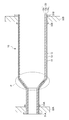
- FIG. 2 is a cross-sectional view showing an example of the configuration of the piping according to the present embodiment.
- the pipe 10 is formed in a tubular shape by a cylindrical base material 11.
- the pipe 10 includes a cylindrical base material 11, a lining material 12 having an outer diameter smaller than the inner diameter of the base material 11, and a filler 13 that fills a gap between the base material 11 and the lining material 12. Composed.
- the pipe 10 has, in its cross section, a layer made of a base material 11 (hereinafter referred to as “base material layer 11 s”) and a layer made of a lining material 12 (hereinafter referred to as “lining material layer 12 s”). And a layer made of the filler 13 filling the base material layer and the lining material layer (hereinafter referred to as “filler layer 13s”), and this three-layer structure 20 is integrated. And is formed into a tubular shape.
- the three-layer structure 20 is also expressed as “base material layer 11 s / filler layer 13 s / lining material layer 12 s”, but this is directed from the outside (outer layer) to the inside (inner layer) in the pipe 10. This means that the base material layer 11s, the filler layer 13s, and the lining material layer 12s have a layered structure.
- the base material 11 consists of cylindrical materials, and comprises the base material of the piping 10 which is a tubular structure.
- the base material 11 is made of a material having corrosion resistance, and preferably made of stainless steel, nickel or a nickel alloy, titanium or a titanium alloy, cobalt or a cobalt alloy, or the like.
- stainless steel is an inexpensive material, and it can obtain corrosion resistance at a relatively low cost and effectively. Further, nickel or nickel alloy, titanium or titanium alloy, cobalt or cobalt alloy can obtain higher corrosion resistance.
- the pipe 10 when the pipe 10 is a pipe having a different outer diameter on the upstream side and the downstream side to which the slurry is transferred, that is, a so-called different diameter pipe, the portion where the outer diameter changes (FIG.
- the base material 11 may be made of a substantially conical material.
- the thickness of the base material 11, that is, the thickness of the base material layer 11 s when viewed in cross section, is not particularly limited as long as the corrosion resistance can be effectively exhibited, but may be, for example, about 5 mm to 15 mm.
- the thickness of the base material 11 depends on the size of the pipe 10, for example, the total length or the pipe diameter, it is preferable to appropriately adjust according to the size.
- the lining material 12 is made of a cylindrical material like the base material 11 and has an outer diameter smaller than the inner diameter of the base material 11 and is arranged inside the base material 11.
- This lining material 12 constitutes a lining material layer 12s when viewed in cross section, that is, a three-layer structure 20 of a base material layer 11s / filling material layer 13s / lining material layer 12s constituting the tubular shape of the pipe 10.
- the lining material 12 is composed of a substantially conical material in the same manner as the base material 11 in the portion where the outer diameter changes (portion indicated by “P” in FIG. 2). To do.
- the lining material 12 is made of a material having wear resistance, and preferably made of ceramics. As described above, the lining material 12 is located on the innermost side of the pipe 10 and is in contact with the slurry passing through the pipe 10 and the steam containing the slurry, and the lining material 12 has wear resistance. By forming with a material, abrasion of the piping 10 at the time of transfer of a slurry etc. can be prevented effectively.
- ceramics have a heat-resistant temperature of 1000 ° C. or higher and excellent wear resistance. Wear resistance can be effectively imparted by forming the lining material 12 preferably with ceramics. Moreover, it is more preferable that the ceramic contains silicon carbide. According to the ceramic containing silicon carbide, not only abrasion resistance but also acid resistance and corrosion resistance can be imparted to the lining material 12.
- the thickness of the lining material 12, that is, the thickness of the lining material layer 12 s when viewed in cross section is not particularly limited as long as the wear resistance can be effectively exhibited, and can be, for example, about 4 mm to 10 mm. Note that the thickness of the lining material layer 12 also depends on the size of the pipe 10 such as the overall length and the pipe diameter, and also depends on the thickness of the base material 11, and therefore depends on the size. It is preferable to adjust appropriately.
- Filler Filler 13 is for filling the gap between base material 11 and lining material 12 and bonding them, and is positioned between base material layer 11s and lining material layer 12s when viewed in cross section.
- the filler layer 13s which is an intermediate layer, is configured.
- the filler 13 is composed of, for example, cement or a material containing cement. More specifically, it can be configured using mortar. Mortar is particularly preferable because it is easy to obtain and can be easily applied when filling the gap between the base material 11 and the lining material 12.
- the thickness of the filler 13, that is, the thickness of the filler layer 13 s when viewed in cross section is not particularly limited as long as the gap between the base material 11 and the lining material 12 can be effectively filled. For example, about 2 mm to 8 mm It can be. Note that the thickness of the filler layer 13 also depends on the size of the pipe 10 such as the total length and the pipe diameter, and also depends on the thickness of the base material 11 and the lining material 12. It is preferable to adjust appropriately according to the size.
- the pipe 10 includes the base material layer 11s formed of the base material 11 constituting the outer layer and having the corrosion resistance, and the lining material 12 constituting the inner layer and having the wear resistance.
- the lining material layer 12s is formed in a tubular shape by a three-layer structure of a filler material layer 13s made of a filler material 13 that fills a gap between the base material 11 and the lining material 12.
- the pipe 10 is made of, for example, a base material layer 11s made of stainless steel having a thickness of 8 mm, a lining material layer 12s made of ceramics having a thickness of 7 mm, and a stainless steel having a thickness of 5 mm, for example. It is formed in a tubular shape by a three-layer structure with a filler layer 13s made of mortar.
- the pipe 10 formed into a tubular shape with such a three-layer structure it is possible to effectively suppress wear and corrosion when transferring slurry or steam containing the slurry, and effectively prevent leakage of the slurry and steam. can do. Further, even when the wear progresses with the transfer of the slurry and the lining material 12 is partially lost, the base material 11 can be prevented from being worn out immediately because the filler 13 exists outside the lining material 12. it can. Furthermore, even if the filler 13 is partially lost due to wear, the base material 11 is made of a material having corrosion resistance, so that it can be prevented that a hole or the like is immediately opened. .
- the pipe 10 having such a configuration, it is only necessary to periodically replace the lining material 12 constituting the inner layer during maintenance, so that repair costs can be suppressed and the life of the pipe is prolonged. be able to.
- Piping shape and other configurations >> Although it does not specifically limit as the piping 10 which concerns on this Embodiment, As shown to the cross-sectional schematic diagram of FIG. 2, the piping from which an outer diameter differs in the upstream and downstream which a slurry is transferred, what is called a different diameter piping. can do.
- the different-diameter pipe has a portion (a portion indicated by “P” in FIG. 2) whose outer diameter changes.
- the pipe 10 is formed in a tubular shape by a three-layer structure of “base material layer 11s / filling material layer 13s / lining material layer 12s”.
- base material layer 11s / filling material layer 13s / lining material layer 12s the pipe 10 is formed in a tubular shape by a three-layer structure of “base material layer 11s / filling material layer 13s / lining material layer 12s”.
- the stub ends 31A and 31B can be provided at both ends of the upstream side and the downstream side where the slurry is transferred. And it is preferable to provide flange 32A, 32B in the back side of stub end 31A, 31B provided in both ends. Further, in the pipe 10, stub ends 31A and 31B and stoppers 33A and 33B are provided at both ends thereof, and flanges 32A and 32B are provided between the stub ends 31A and 31B and the stoppers 33A and 33B. Good.
- the piping is easy to disassemble and assemble.
- the stub ends 31A and 31B are provided at both ends, and the flanges 32A and 32B are provided on the back side of the stub ends 31A and 31B, so that the flanges 32A and 32B are loose with respect to the pipe 10. It can be in a state, that is, a state where it can be freely rotated.
Landscapes
- Engineering & Computer Science (AREA)
- General Engineering & Computer Science (AREA)
- Mechanical Engineering (AREA)
- Chemical & Material Sciences (AREA)
- Ceramic Engineering (AREA)
- Rigid Pipes And Flexible Pipes (AREA)
- Protection Of Pipes Against Damage, Friction, And Corrosion (AREA)
- Flanged Joints, Insulating Joints, And Other Joints (AREA)
Abstract
Description
配管に犠牲板を取り付ける方法は、配管と同じ材質で厚みを持つ犠牲板を配管内の特定の箇所に溶接で取り付ける方法である。高温高圧下において酸性スラリーを移送する配管には、耐腐食性が必要であるため、その犠牲板にはチタン等の高価な材料を使用している。したがって、この方法は、施工としては容易であるがコストが高くなってしまう。また、チタン等の材料は、耐腐食性はあるものの耐摩耗性がないため、寿命を延ばすべく板厚を増加しても数ヶ月で消耗してしまい、再補修もしくは取替が必要となってしまう。このことから、犠牲板を取り付ける方法は、得られる効果が限定的であり、しかもその実施には作業コストの上昇を伴う。
緩衝材としては、主にゴム系材料に代表される。ところが、HPALプロセスにおけるスラリーを昇温する処理では、そのスラリーを100℃~200℃程度まで昇温するため、耐熱性を持たないゴム系材料からなる緩衝材をスラリーやスラリーを含む蒸気を送るための配管へ適用することは困難である。
流体摩耗に対する耐摩耗材料に関しては、硬化肉盛や高分子ポリエチレンに見られるように多くの材料が使用されているが、これらの一般的な耐摩耗材料は、常温下の使用に限定されることや酸性雰囲気では脆弱である。そのため、高温高圧下の酸性スラリーを移送する条件に合致するものとしては、セラミック等の限定された材料となる。セラミックが使われた配管としてはセラミックライニング鋼管が多く使用されているが、このセラミックライニング鋼管は、セラミックの耐摩耗性に主眼を置いているため、配管の母材となる部分には炭素鋼を用いている。このように、セラミックライニング鋼管においても、母材として炭素鋼を使用しているため、ライニングであるセラミックに亀裂等の欠陥が生じた場合には、酸性スラリーが耐腐食性に乏しい炭素鋼を短時間で腐食してしまい、その結果として配管に孔が開いてしまう。
本実施の形態に係る配管は、スラリー、又はスラリーを含む蒸気を送るための配管である。この配管は、例えば、ニッケル酸化鉱石のスラリーに対して高温、高圧下で硫酸等によりニッケルを浸出させるHPALプロセスにおけるプラントに用いることができる。より具体的には、ニッケル酸化鉱石のスラリーを段階的に昇温、昇圧して、オートクレーブに移送するための移送配管として用いることができ、この配管においては、スラリーのみならず、そのスラリーを含む蒸気も移送される。
図2は、本実施の形態に係る配管の構成の一例を示した断面図である。図2に示すように、配管10は、円筒形の母材11によって管状に形成されている。そして、この配管10は、円筒形の母材11と、その母材11の内径よりも小さい外径を有するライニング材12と、母材11とライニング材12との隙間を埋める充填材13とから構成される。
母材11は、円筒形の材料からなり、管状構造である配管10の母体を構成する。母材11は、耐腐食性を有する材料から構成され、好ましくは、ステンレス、ニッケル又はニッケル合金、チタン又はチタン合金、コバルト又はコバルト合金等から構成される。
ライニング材12は、母材11と同様に円筒形の材料からなり、母材11の内径よりも小さい外径を有して母材11の内側に配置される。このライニング材12は、断面視したときのライニング材層12sを構成するものであり、つまり、配管10の管状を構成する母材層11s/充填材層13s/ライニング材層12sの3層構造20において、最も内側に位置する内層となるものである。
充填材13は、母材11とライニング材12との隙間を埋めて接着させるためのものであり、断面視したときの母材層11sとライニング材層12sとの間に位置する中間層である充填材層13sを構成する。
本実施の形態に係る配管10としては、特に限定されないが、図2の断面模式図に示すように、スラリーが移送される上流側と下流側とで外径の異なる配管、いわゆる異径配管とすることができる。異径配管は、その外径が変化する部分(図2中の「P」で示す部分)を有している。
11 母材
11s 母材層
12 ライニング材
12s ライニング材層
13 充填材
13s 充填材層
20 3層構造
31A,31B スタブエンド
32A,32B フランジ
33A,33B ストッパー
100 プラント設備
51 第1のヒータータンク
52,53,54 遠心ポンプ
55 第2のヒータータンク
56,57 自動弁
Claims (7)
- スラリー、又はスラリーを含む蒸気を送るための配管であって、
外層を構成する耐腐食性を有する母材層と、内層を構成する耐摩耗性を有するライニング材層と、該母材層と該ライニング材層との隙間を埋めるための充填材層との3層構造により管状に形成されている
ことを特徴とする配管。 - 上流側と下流側とで外径が異なる異径配管である
ことを特徴とする請求項1に記載の配管。 - 前記充填材層を構成する材料は、モルタルである
ことを特徴とする請求項1又は2に記載の配管。 - 前記ライニング材層を構成する材料は、セラミックスである
ことを特徴とする請求項1乃至3のいずれか1項に記載の配管。 - 前記ライニング材層を構成する材料は、炭化珪素を含むセラミックスである
ことを特徴とする請求項1乃至4のいずれか1項に記載の配管。 - 高圧酸浸出によりニッケル酸化鉱石からニッケルを浸出させて回収する湿式製錬処理を行うためのプラントで使用される
ことを特徴とする請求項1乃至5のいずれか1項に記載の配管。 - 当該配管の両末端にスタブエンドが設けられており、該スタブエンドの背面側にフランジが設けられている
ことを特徴とする請求項1乃至6のいずれか1項に記載の配管。
Priority Applications (3)
| Application Number | Priority Date | Filing Date | Title |
|---|---|---|---|
| EP16803145.8A EP3306159A4 (en) | 2015-06-02 | 2016-05-24 | PIPING |
| AU2016273662A AU2016273662B2 (en) | 2015-06-02 | 2016-05-24 | Piping |
| PH12017502185A PH12017502185B1 (en) | 2015-06-02 | 2017-11-29 | Piping |
Applications Claiming Priority (2)
| Application Number | Priority Date | Filing Date | Title |
|---|---|---|---|
| JP2015112148A JP2016223579A (ja) | 2015-06-02 | 2015-06-02 | 配管 |
| JP2015-112148 | 2015-06-02 |
Publications (1)
| Publication Number | Publication Date |
|---|---|
| WO2016194710A1 true WO2016194710A1 (ja) | 2016-12-08 |
Family
ID=57441080
Family Applications (1)
| Application Number | Title | Priority Date | Filing Date |
|---|---|---|---|
| PCT/JP2016/065335 Ceased WO2016194710A1 (ja) | 2015-06-02 | 2016-05-24 | 配管 |
Country Status (5)
| Country | Link |
|---|---|
| EP (1) | EP3306159A4 (ja) |
| JP (1) | JP2016223579A (ja) |
| AU (1) | AU2016273662B2 (ja) |
| PH (1) | PH12017502185B1 (ja) |
| WO (1) | WO2016194710A1 (ja) |
Citations (8)
| Publication number | Priority date | Publication date | Assignee | Title |
|---|---|---|---|---|
| JPS5877990A (ja) * | 1981-11-05 | 1983-05-11 | 東芝セラミツクス株式会社 | 耐摩耗性配管 |
| JPH03124097U (ja) * | 1990-03-30 | 1991-12-17 | ||
| JPH0642693A (ja) * | 1991-11-26 | 1994-02-18 | Onoda Cement Co Ltd | 水和硬化組成物及びこれを用いたセラミックスライニング管 |
| JPH06249393A (ja) * | 1993-02-26 | 1994-09-06 | Onoda Cement Co Ltd | セラミックスライニング管 |
| JPH07119873A (ja) * | 1993-10-25 | 1995-05-12 | Sekisui Chem Co Ltd | ライニング管のフランジ継手部の形成方法 |
| JP2001050474A (ja) * | 1999-08-05 | 2001-02-23 | Mitsubishi Heavy Ind Ltd | 配管の耐摩耗構造 |
| JP3136954U (ja) * | 2007-08-27 | 2007-11-08 | ノーラエンジニアリング株式会社 | ルーズフランジ式管継手 |
| JP2014057955A (ja) * | 2012-04-26 | 2014-04-03 | Sumitomo Metal Mining Co Ltd | 高圧酸浸出工程におけるオートクレーブへの原料スラリーと硫酸の添加方法及びオートクレーブ |
Family Cites Families (7)
| Publication number | Priority date | Publication date | Assignee | Title |
|---|---|---|---|---|
| JPS55132480A (en) * | 1979-04-04 | 1980-10-15 | Kubota Ltd | Metal pipe |
| JPH0582942U (ja) * | 1992-04-14 | 1993-11-09 | 株式会社熊谷組 | 砂等の水搬装置 |
| DE9320465U1 (de) * | 1993-05-05 | 1994-08-04 | Leidig, Olaf, Dipl.-Ing., 45141 Essen | Fördermittel für den insbesondere pneumatischen oder hydraulischen Transport von abrasiven Gütern |
| JP2001279474A (ja) * | 2000-03-30 | 2001-10-10 | Kobe Steel Ltd | 耐食性銅又は銅合金管継手 |
| JP4624391B2 (ja) * | 2007-09-28 | 2011-02-02 | パンパシフィック・カッパー株式会社 | 乾燥精鉱の移送管配管構造における移送管の破損検知方法 |
| US9068244B2 (en) * | 2012-04-06 | 2015-06-30 | Sumitomo Metal Mining Co., Ltd. | Method for recovering chromite, and method for wet smelting of nickel oxide ore |
| US9429267B2 (en) * | 2013-05-07 | 2016-08-30 | Donald C. Dunn | Pipe systems |
-
2015
- 2015-06-02 JP JP2015112148A patent/JP2016223579A/ja active Pending
-
2016
- 2016-05-24 EP EP16803145.8A patent/EP3306159A4/en not_active Withdrawn
- 2016-05-24 WO PCT/JP2016/065335 patent/WO2016194710A1/ja not_active Ceased
- 2016-05-24 AU AU2016273662A patent/AU2016273662B2/en not_active Ceased
-
2017
- 2017-11-29 PH PH12017502185A patent/PH12017502185B1/en unknown
Patent Citations (8)
| Publication number | Priority date | Publication date | Assignee | Title |
|---|---|---|---|---|
| JPS5877990A (ja) * | 1981-11-05 | 1983-05-11 | 東芝セラミツクス株式会社 | 耐摩耗性配管 |
| JPH03124097U (ja) * | 1990-03-30 | 1991-12-17 | ||
| JPH0642693A (ja) * | 1991-11-26 | 1994-02-18 | Onoda Cement Co Ltd | 水和硬化組成物及びこれを用いたセラミックスライニング管 |
| JPH06249393A (ja) * | 1993-02-26 | 1994-09-06 | Onoda Cement Co Ltd | セラミックスライニング管 |
| JPH07119873A (ja) * | 1993-10-25 | 1995-05-12 | Sekisui Chem Co Ltd | ライニング管のフランジ継手部の形成方法 |
| JP2001050474A (ja) * | 1999-08-05 | 2001-02-23 | Mitsubishi Heavy Ind Ltd | 配管の耐摩耗構造 |
| JP3136954U (ja) * | 2007-08-27 | 2007-11-08 | ノーラエンジニアリング株式会社 | ルーズフランジ式管継手 |
| JP2014057955A (ja) * | 2012-04-26 | 2014-04-03 | Sumitomo Metal Mining Co Ltd | 高圧酸浸出工程におけるオートクレーブへの原料スラリーと硫酸の添加方法及びオートクレーブ |
Non-Patent Citations (1)
| Title |
|---|
| See also references of EP3306159A4 * |
Also Published As
| Publication number | Publication date |
|---|---|
| JP2016223579A (ja) | 2016-12-28 |
| AU2016273662B2 (en) | 2019-05-23 |
| EP3306159A4 (en) | 2019-02-27 |
| PH12017502185B1 (en) | 2021-09-24 |
| AU2016273662A1 (en) | 2017-12-21 |
| PH12017502185A1 (en) | 2018-05-28 |
| EP3306159A1 (en) | 2018-04-11 |
Similar Documents
| Publication | Publication Date | Title |
|---|---|---|
| US11466942B2 (en) | Anti-erosion device for a shell-and-tube equipment | |
| CH701215B1 (it) | Tubo metallico resistente alla corrosione e suo utilizzo in apparecchiature a fascio tubiero. | |
| CN103528705B (zh) | 可拆卸高压多点柔性热电偶 | |
| US9464750B2 (en) | Tubular component with an internal wear-resistant surface | |
| WO2016194710A1 (ja) | 配管 | |
| CN204607941U (zh) | 用于传输高温气化原气和流体的废料的装置 | |
| CN105170037B (zh) | 流化床反应器 | |
| CN107131363A (zh) | 一种应用于海底的混凝土输水管道 | |
| CN202302287U (zh) | 一种耐高温防漏回转阀阀芯 | |
| JP6226027B1 (ja) | アングル弁 | |
| CN103939698A (zh) | 高炉冲渣管弯头 | |
| CN203816891U (zh) | 一种全管式固定筛装置 | |
| CN104180367A (zh) | 一种流化床锅炉排渣管 | |
| JP2006009052A (ja) | 防食方法 | |
| Sriskandarajah et al. | Contribution of liner strength in CRA lined pipes | |
| JP6720946B2 (ja) | アングル弁 | |
| JP2016013881A (ja) | サージホッパーに用いられるダンパー軸 | |
| JP2025087338A (ja) | 蓋体及び排気口閉鎖装置 | |
| CN207775268U (zh) | 具有双层冷却结构的高炉u型冲渣槽 | |
| Bumstead et al. | Improvements in autoclave availability at Vale’s Long Harbour refinery | |
| CN223019612U (zh) | 出口管和用于出口管的磨损模块 | |
| CN101837203A (zh) | 浓密机壳体 | |
| CN207777800U (zh) | 一种钛白粉生产过程中防磨损破裂的冷却管道结构 | |
| Van Laar et al. | OneSteel Whyalla Blast Furnace Campaign Extension | |
| CN204477326U (zh) | 一种氟塑料衬里蝶阀 |
Legal Events
| Date | Code | Title | Description |
|---|---|---|---|
| 121 | Ep: the epo has been informed by wipo that ep was designated in this application |
Ref document number: 16803145 Country of ref document: EP Kind code of ref document: A1 |
|
| DPE1 | Request for preliminary examination filed after expiration of 19th month from priority date (pct application filed from 20040101) | ||
| WWE | Wipo information: entry into national phase |
Ref document number: 12017502185 Country of ref document: PH |
|
| NENP | Non-entry into the national phase |
Ref country code: DE |
|
| ENP | Entry into the national phase |
Ref document number: 2016273662 Country of ref document: AU Date of ref document: 20160524 Kind code of ref document: A |
|
| WWE | Wipo information: entry into national phase |
Ref document number: 2016803145 Country of ref document: EP |