WO2016194735A1 - Dispositif de commande de moteur à combustion interne - Google Patents
Dispositif de commande de moteur à combustion interne Download PDFInfo
- Publication number
- WO2016194735A1 WO2016194735A1 PCT/JP2016/065459 JP2016065459W WO2016194735A1 WO 2016194735 A1 WO2016194735 A1 WO 2016194735A1 JP 2016065459 W JP2016065459 W JP 2016065459W WO 2016194735 A1 WO2016194735 A1 WO 2016194735A1
- Authority
- WO
- WIPO (PCT)
- Prior art keywords
- air
- fuel ratio
- amount
- temperature
- scr catalyst
- Prior art date
- Legal status (The legal status is an assumption and is not a legal conclusion. Google has not performed a legal analysis and makes no representation as to the accuracy of the status listed.)
- Ceased
Links
Images


Classifications
-
- F—MECHANICAL ENGINEERING; LIGHTING; HEATING; WEAPONS; BLASTING
- F01—MACHINES OR ENGINES IN GENERAL; ENGINE PLANTS IN GENERAL; STEAM ENGINES
- F01N—GAS-FLOW SILENCERS OR EXHAUST APPARATUS FOR MACHINES OR ENGINES IN GENERAL; GAS-FLOW SILENCERS OR EXHAUST APPARATUS FOR INTERNAL-COMBUSTION ENGINES
- F01N3/00—Exhaust or silencing apparatus having means for purifying, rendering innocuous, or otherwise treating exhaust
- F01N3/08—Exhaust or silencing apparatus having means for purifying, rendering innocuous, or otherwise treating exhaust for rendering innocuous
-
- F—MECHANICAL ENGINEERING; LIGHTING; HEATING; WEAPONS; BLASTING
- F01—MACHINES OR ENGINES IN GENERAL; ENGINE PLANTS IN GENERAL; STEAM ENGINES
- F01N—GAS-FLOW SILENCERS OR EXHAUST APPARATUS FOR MACHINES OR ENGINES IN GENERAL; GAS-FLOW SILENCERS OR EXHAUST APPARATUS FOR INTERNAL-COMBUSTION ENGINES
- F01N3/00—Exhaust or silencing apparatus having means for purifying, rendering innocuous, or otherwise treating exhaust
- F01N3/08—Exhaust or silencing apparatus having means for purifying, rendering innocuous, or otherwise treating exhaust for rendering innocuous
- F01N3/10—Exhaust or silencing apparatus having means for purifying, rendering innocuous, or otherwise treating exhaust for rendering innocuous by thermal or catalytic conversion of noxious components of exhaust
- F01N3/24—Exhaust or silencing apparatus having means for purifying, rendering innocuous, or otherwise treating exhaust for rendering innocuous by thermal or catalytic conversion of noxious components of exhaust characterised by constructional aspects of converting apparatus
- F01N3/28—Construction of catalytic reactors
-
- F—MECHANICAL ENGINEERING; LIGHTING; HEATING; WEAPONS; BLASTING
- F01—MACHINES OR ENGINES IN GENERAL; ENGINE PLANTS IN GENERAL; STEAM ENGINES
- F01N—GAS-FLOW SILENCERS OR EXHAUST APPARATUS FOR MACHINES OR ENGINES IN GENERAL; GAS-FLOW SILENCERS OR EXHAUST APPARATUS FOR INTERNAL-COMBUSTION ENGINES
- F01N3/00—Exhaust or silencing apparatus having means for purifying, rendering innocuous, or otherwise treating exhaust
- F01N3/08—Exhaust or silencing apparatus having means for purifying, rendering innocuous, or otherwise treating exhaust for rendering innocuous
- F01N3/10—Exhaust or silencing apparatus having means for purifying, rendering innocuous, or otherwise treating exhaust for rendering innocuous by thermal or catalytic conversion of noxious components of exhaust
- F01N3/24—Exhaust or silencing apparatus having means for purifying, rendering innocuous, or otherwise treating exhaust for rendering innocuous by thermal or catalytic conversion of noxious components of exhaust characterised by constructional aspects of converting apparatus
- F01N3/36—Arrangements for supply of additional fuel
-
- F—MECHANICAL ENGINEERING; LIGHTING; HEATING; WEAPONS; BLASTING
- F02—COMBUSTION ENGINES; HOT-GAS OR COMBUSTION-PRODUCT ENGINE PLANTS
- F02D—CONTROLLING COMBUSTION ENGINES
- F02D41/00—Electrical control of supply of combustible mixture or its constituents
- F02D41/02—Circuit arrangements for generating control signals
- F02D41/04—Introducing corrections for particular operating conditions
-
- Y—GENERAL TAGGING OF NEW TECHNOLOGICAL DEVELOPMENTS; GENERAL TAGGING OF CROSS-SECTIONAL TECHNOLOGIES SPANNING OVER SEVERAL SECTIONS OF THE IPC; TECHNICAL SUBJECTS COVERED BY FORMER USPC CROSS-REFERENCE ART COLLECTIONS [XRACs] AND DIGESTS
- Y02—TECHNOLOGIES OR APPLICATIONS FOR MITIGATION OR ADAPTATION AGAINST CLIMATE CHANGE
- Y02T—CLIMATE CHANGE MITIGATION TECHNOLOGIES RELATED TO TRANSPORTATION
- Y02T10/00—Road transport of goods or passengers
- Y02T10/10—Internal combustion engine [ICE] based vehicles
- Y02T10/12—Improving ICE efficiencies
Definitions
- the present invention relates to a control device applied to an internal combustion engine in which a selective reduction catalyst (SCR (Selective Catalytic Reduction) catalyst) is arranged in an exhaust passage.
- SCR Selective Catalytic Reduction
- NH 3 adsorbed on the SCR catalyst can be discharged into the atmosphere. If there is sex, by the air-fuel ratio of the mixture for the combustion in the internal combustion engine to the weak lean air-fuel ratio, NO X discharged from the internal combustion engine, and the desorbed NO X from the NSR catalyst SCR catalyst Is known, and the NH 3 adsorbed on the SCR catalyst is consumed (see, for example, Patent Document 1).
- Patent Document 2 in an internal combustion engine in which an SCR catalyst and an injection nozzle for injecting urea or NH 3 into exhaust gas upstream of the SCR catalyst are arranged in an exhaust passage, the temperature of the SCR catalyst suddenly rises.
- a technique for reacting NH 3 desorbed from the SCR catalyst with NO X by stopping the injection of urea or NH 3 from the injection nozzle and increasing the amount of NO X discharged from the internal combustion engine. ing.
- JP 2012-237296 A Japanese Patent No. 4542455
- the present invention has been made in view of the above-described circumstances, and an object of the present invention is to reduce deterioration in fuel consumption rate in a control device applied to an internal combustion engine in which an NSR catalyst and an SCR catalyst are arranged in an exhaust passage.
- the present invention provides a technique capable of reducing the amount of NH 3 discharged from the SCR catalyst while suppressing the amount of NH 3 .
- the present invention is a control device applied to an internal combustion engine in which an NSR catalyst and an SCR catalyst are arranged in an exhaust passage, and reduces NH 3 adsorbed on the SCR catalyst. If necessary, if the temperature of the SCR catalyst is equal to or higher than the lower oxidizable temperature of NH 3 , the air-fuel ratio of the mixture burned in the internal combustion engine is controlled to a predetermined lean air-fuel ratio higher than the stoichiometric air-fuel ratio, If the temperature of the SCR catalyst is lower than the lower limit temperature, the air-fuel ratio of the air-fuel mixture burned in the internal combustion engine is controlled to a predetermined weak lean air-fuel ratio that is lower than the predetermined lean air-fuel ratio and higher than the stoichiometric air-fuel ratio. I made it.
- the present invention provides a first exhaust purification device that is disposed in an exhaust passage and includes an NSR catalyst, and a second exhaust purification that is disposed in an exhaust passage downstream of the first exhaust purification device and includes an SCR catalyst.
- a control device applied to an internal combustion engine including apparatus and, a control device, an acquisition unit that acquires adsorbed NH 3 amount is an amount of NH 3 that is adsorbed on the SCR catalyst, the SCR catalyst
- the NH 3 adsorption amount acquired by the acquisition means is equal to or higher than a predetermined threshold
- the temperature detected by the detection means is equal to or higher than the lower limit temperature at which NH 3 can be oxidized.
- Air-fuel mixture For example, if the air-fuel ratio of the air-fuel mixture burned in the internal combustion engine is controlled to a predetermined lean air-fuel ratio higher than the stoichiometric air-fuel ratio, and the temperature detected by the detection means is less than the lower limit temperature, Air-fuel mixture The ratio lower than the predetermined lean air-fuel ratio, given the weak lean amount of the NO X increases to and flows out per unit time than the amount of the NO X which are inserted into the NSR catalyst per unit time from the NSR catalyst And a control means for controlling the air-fuel ratio.
- the “predetermined threshold value” means that when the NH 3 adsorption amount of the SCR catalyst is equal to or greater than the predetermined threshold value, the internal combustion engine is operated under an operating condition in which NH 3 adsorbed on the SCR catalyst is easily desorbed. And the amount of NH 3 that is desorbed from the SCR catalyst and discharged into the atmosphere exceeds an allowable amount (for example, the maximum amount that does not cause an irritating odor), or the NH 3 3 is an amount obtained by subtracting a predetermined margin from the adsorption amount, it is assumed to be determined by calibration tasks using the experiment or the like in advance.
- an allowable amount for example, the maximum amount that does not cause an irritating odor
- the mixture when the NH 3 adsorption amount acquired by the acquisition unit is equal to or higher than the predetermined threshold, if the temperature detected by the detection unit is lower than the lower limit temperature, the mixture is empty.
- the fuel ratio is controlled to a predetermined weak lean air-fuel ratio.
- the predetermined weak lean air-fuel ratio at that time is lower than the predetermined lean air-fuel ratio, and the NO x flowing out from the NSR catalyst per unit time as compared with the amount of NO x stored in the NSR catalyst per unit time. This is the air-fuel ratio in which the amount of air increases.
- the air-fuel ratio of the air-fuel mixture is controlled to the predetermined weak lean air-fuel ratio when the temperature of the SCR catalyst is lower than the lower limit temperature, a relatively large amount of NO x flows out from the NSR catalyst. As a result, NH 3 adsorbed on the SCR catalyst is consumed by reacting with NO x flowing out from the NSR catalyst.
- the predetermined lean air-fuel ratio may be the highest air-fuel ratio within the range of the air-fuel ratio that can ensure the combustion stability and drivability of the internal combustion engine, or exhaust emissions other than NH 3 are regulated. It may be the highest air-fuel ratio within a range not exceeding the value.
- the operating state of the internal combustion engine when the NH 3 adsorption amount acquired by the acquiring unit is equal to or greater than the predetermined threshold is in a lean operating region (an operating region where the air-fuel ratio of the mixture is set to the lean air-fuel ratio). If so, the predetermined lean air-fuel ratio may be made equal to the air-fuel ratio determined according to the operating state of the internal combustion engine.
- the air-fuel ratio of the air-fuel mixture is controlled to the predetermined lean air-fuel ratio, exhaust gas containing a relatively large amount of oxygen is supplied to the SCR catalyst.
- the control apparatus for an internal combustion engine of the present invention when the adsorbed NH 3 amount of the SCR catalyst is equal to or greater than a predetermined threshold value, it is possible to reduce the amount of NH 3 that is adsorbed on the SCR catalyst . As a result, since the NH 3 adsorption amount of the SCR catalyst is suppressed from exceeding the predetermined threshold value, it is possible to suppress discharge of NH 3 from the SCR catalyst that is larger than the above-described allowable amount.
- control device for an internal combustion engine may control the air-fuel ratio of the air-fuel mixture when the NH 3 adsorption amount is equal to or higher than the predetermined threshold and the temperature of the SCR catalyst is equal to or higher than the lower limit temperature.
- the NH 3 adsorption amount of the SCR catalyst is reduced, so that the air-fuel ratio of the air-fuel mixture is reduced to a predetermined weak lean air-fuel ratio compared to the above-mentioned conventional technology Can reduce the chance of As a result, it is possible to reduce the amount of NH 3 discharged from the SCR catalyst while suppressing the deterioration of the fuel consumption rate.
- the control unit is A temperature raising process for raising the temperature of the selective catalytic reduction catalyst may be performed.
- the SCR catalyst has a characteristic that when the temperature of the SCR catalyst is increased to some extent, the amount of NH 3 that can be adsorbed by the SCR catalyst decreases as the temperature of the SCR catalyst increases. Therefore, when the temperature of the SCR catalyst becomes equal to or higher than the predetermined temperature higher than the lower limit temperature, the amount of NH 3 desorbed from the SCR catalyst per unit time as compared with the amount of NH 3 oxidized per unit time in the SCR catalyst. The amount increases. Accordingly, when the NH 3 adsorption amount of the SCR catalyst is equal to or higher than the predetermined threshold value, if the temperature of the SCR catalyst is equal to or higher than the predetermined temperature, the SCR catalyst is heated to actively raise the NH 3 from the SCR catalyst.
- the temperature increase process is performed so that the amount of NH 3 desorbed from the SCR catalyst during the temperature increase process is within an amount that does not generate an irritating odor.
- the temperature raising process may be performed by a method of retarding the ignition timing of the internal combustion engine or a method of advancing the valve opening timing of the exhaust valve of the internal combustion engine. In that case, the NH 3 adsorption amount of the SCR catalyst can be reduced while suppressing the deterioration of the fuel consumption rate to a small extent.
- the air-fuel ratio of the air-fuel mixture when the temperature raising process is executed may be set to be equal to the air-fuel ratio determined according to the operating state of the internal combustion engine, but is equal to the predetermined lean air-fuel ratio. It may be set.
- the air-fuel ratio of the air-fuel mixture is set to the predetermined lean air-fuel ratio when the temperature raising process is executed, the NH 3 adsorption amount of the SCR catalyst can be reduced while suppressing the deterioration of the fuel consumption rate. it can.
- the control device for the internal combustion engine described above is also effective when the first exhaust purification device includes an NSR catalyst and a three-way catalyst.
- the first exhaust purification device includes the NSR catalyst and the three-way catalyst
- NH 3 is also produced in the three-way catalyst. Therefore, when the first exhaust purification device includes the NSR catalyst and the three-way catalyst, the NH 3 adsorption amount of the SCR catalyst is greater than or equal to the predetermined threshold value compared to the case where the first exhaust purification device includes only the NSR catalyst. More opportunities to become.
- the control device for an internal combustion engine according to the present invention is applied to the configuration in which the first exhaust purification device includes the NSR catalyst and the three-way catalyst, the fuel consumption rate when reducing the NH 3 adsorption amount of the SCR catalyst is reduced. Deterioration can be suppressed more effectively.
- the present invention it is possible to reduce the amount of NH 3 discharged from the SCR catalyst while suppressing deterioration of the fuel consumption rate.
- FIG. 1 is a diagram showing a schematic configuration of an internal combustion engine to which the present invention is applied and its exhaust system.
- An internal combustion engine 1 shown in FIG. 1 is a spark ignition type internal combustion engine (gasoline engine) that can be operated by an air / fuel ratio (lean air / fuel ratio) higher than the stoichiometric air / fuel ratio.
- the internal combustion engine 1 includes a fuel injection valve 2.
- the fuel injection valve 2 may be a valve device that injects fuel into an intake passage (for example, an intake port), or may be a valve device that injects fuel into a cylinder.
- the internal combustion engine 1 is connected to the exhaust pipe 3.
- the exhaust pipe 3 is a pipe through which gas (exhaust gas) combusted in the cylinder of the internal combustion engine 1 flows.
- a first catalyst casing 4 is disposed in the middle of the exhaust pipe 3.
- the first catalyst casing 4 contains a three-way catalyst composed of a honeycomb structure covered with a coat layer such as alumina and a noble metal (for example, platinum, palladium, rhodium, etc.) supported on the coat layer. To do.
- a second catalyst casing 5 is disposed in the exhaust pipe 3 downstream of the first catalyst casing 4.
- the second catalyst casing 5 includes a honeycomb structure covered with a coat layer such as alumina, a noble metal (platinum, palladium, rhodium, etc.) supported on the coat layer, and an NO x storage agent (alkaline) supported on the coat layer. Occlusion, alkaline earth, etc.).
- a third catalyst casing 6 is disposed in the exhaust pipe 3 downstream of the second catalyst casing 5.
- the third catalyst casing 6 includes a honeycomb structure made of cordierite or Fe—Cr—Al heat resistant steel, a zeolite coat layer covering the honeycomb structure, and a noble metal (platinum or palladium) supported on the coat layer. Etc.) is contained.
- the combination of the first catalyst casing 4 and the second catalyst casing 5 corresponds to the “first exhaust purification device” according to the present invention.
- the third catalyst casing 6 corresponds to a “second exhaust purification device” according to the present invention.
- the internal combustion engine 1 configured as described above is provided with an ECU 7.
- the ECU 7 is an electronic control unit that includes a CPU, a ROM, a RAM, a backup RAM, and the like.
- the ECU 7 includes an air-fuel ratio sensor (A / F sensor) 8, an oxygen concentration sensor (O 2 sensor) 9, a first NO X sensor 10, a second NO X sensor 11, a temperature sensor 12, an accelerator position sensor 13, and a crank position sensor. 14 and various sensors such as an air flow meter 15 are electrically connected.
- the air-fuel ratio sensor 8 is attached to the exhaust pipe 3 upstream from the first catalyst casing 4 and outputs an electrical signal correlated with the air-fuel ratio of the exhaust flowing into the first catalyst casing 4.
- the oxygen concentration sensor 9 is attached to the exhaust pipe 3 between the first catalyst casing 4 and the second catalyst casing 5 and outputs an electrical signal correlated with the concentration of oxygen contained in the exhaust gas flowing out from the first catalyst casing 4.
- the first NO X sensor 10 is attached to the exhaust pipe 3 between the second catalyst casing 5 and the third catalyst casing 6, and exhaust gas flowing out from the second catalyst casing 5 (in other words, flowing into the third catalyst casing 6). An electrical signal correlated with the concentration of NO x contained in the exhaust gas).
- the second NO x sensor 11 is attached to the exhaust pipe 3 downstream from the third catalyst casing 6 and outputs an electrical signal correlated with the concentration of NO x contained in the exhaust gas flowing out from the third catalyst casing 6.
- the accelerator position sensor 13 outputs an electrical signal that correlates with the amount of operation of the accelerator pedal (accelerator opening).
- the crank position sensor 14 outputs an electrical signal correlated with the rotational position of the output shaft (crankshaft) of the internal combustion engine 1.
- the air flow meter 15 outputs an electrical signal correlated with the amount of air taken into the cylinder of the internal combustion engine 1 (intake air amount).
- the ECU 7 controls the operating state of the internal combustion engine 1 based on the output signals of the various sensors described above. For example, the ECU 7 calculates the target air-fuel ratio of the air-fuel mixture based on the engine speed calculated based on the output signal of the crank position sensor 14 and the output signal (accelerator opening) of the accelerator position sensor 13. The ECU 7 calculates the target fuel injection amount (fuel injection period) of the fuel injection valve 2 based on the target air-fuel ratio and the output signal (intake air amount) of the air flow meter 15, and operates the fuel injection valve 2 according to the target fuel injection amount. Let
- the ECU 7 sets the target air-fuel ratio higher than the stoichiometric air-fuel ratio when the operating state of the internal combustion engine 1 belongs to a low rotation / low load region or an intermediate rotation / medium load region (hereinafter referred to as “lean operation region”).
- lean operation region an intermediate rotation / medium load region
- the ECU 7 sets the target air-fuel ratio to a stoichiometric air-fuel ratio or a rich air-fuel ratio lower than the stoichiometric air-fuel ratio when the operating state of the internal combustion engine 1 is a high load region or a high speed region (hereinafter referred to as “rich operation region”).
- the ECU 7 performs air-fuel ratio feedback control for correcting the target fuel injection amount so that the output signal of the air-fuel ratio sensor 8 matches the target air-fuel ratio, and air-fuel ratio feedback control based on the output signal of the oxygen concentration sensor 9. Learning control of the correction coefficient used is performed.
- the target air-fuel ratio when the target air-fuel ratio is set to a lean air-fuel ratio, the NO x purification performance of the three-way catalyst housed in the first catalyst casing 4 is lowered. Therefore, if the target air-fuel ratio is set to a lean air-fuel ratio, it is necessary to purify NO X in the exhaust gas by the NSR catalyst of the second catalyst casing 5 and the SCR catalyst of the third catalyst casing 6.
- the NSR catalyst occludes or adsorbs NO x in the exhaust when the oxygen concentration of the exhaust flowing into the second catalyst casing 5 is high (when the air-fuel ratio of the exhaust is lean).
- the NSR catalyst has a low oxygen concentration in the exhaust gas flowing into the second catalyst casing 5 and contains a reducing component such as hydrocarbon (HC) or carbon monoxide (CO) (the exhaust air-fuel ratio is rich). sometimes), said NSR catalyst the NO X that was stored discharged to, thereby reducing the released NO X into nitrogen (N 2).
- the rich spike process is a process for adjusting the fuel injection amount and the intake air amount so that the oxygen concentration in the exhaust gas is low and the HC and CO concentrations are high. More specifically, the rich spike process is a process for executing at least one of a process for increasing the fuel injection amount of the fuel injection valve 2 or a process for decreasing the opening of the intake throttle valve (throttle valve). is there.
- the rich spike process may be executed by a method of injecting fuel from the fuel injection valve 2 during the exhaust stroke of the cylinder.
- the rich spike process may be executed when the operation time from the end of the previous rich spike process (preferably, the operation time when the target air-fuel ratio is set to the lean air-fuel ratio) becomes a certain time or more.
- it may be executed when the travel distance from the end of the previous rich spike processing (preferably, the travel distance in which the target air-fuel ratio is set to the lean air-fuel ratio) becomes a certain distance or more.
- the SCR catalyst adsorbs ammonia (NH 3 ) contained in the exhaust gas.
- the SCR catalyst reduces NO x to nitrogen (N 2 ) by reacting NH 3 adsorbed on the SCR catalyst with NO x in the exhaust.
- N 2 nitrogen
- NH 3 supplied to the SCR catalyst is generated in a three-way catalyst or an NSR catalyst. For example, in the case where rich spike processing is executed, a portion of the NO X in the three-way catalyst is reduced to NH 3, part of the NO X flowing out from the NSR catalyst is reduced to NH 3 in the NSR catalyst.
- the amount of NH 3 produced in the NSR catalyst varies depending on the interval at which the rich spike process is executed, the air-fuel ratio at the time when the rich spike process is executed, and the like. Therefore, when NH 3 is supplied to the SCR catalyst, the execution interval of the rich spike processing is set to an interval suitable for the generation of NH 3 , or the air-fuel ratio at the execution of the rich spike processing is an empty space suitable for the generation of NH 3. What is necessary is just to set to an air-fuel ratio (for example, about 14.1).
- the target air-fuel ratio of the air-fuel mixture is set to the stoichiometric air-fuel ratio or the rich air-fuel ratio, so that NO X contained in the exhaust gas becomes the first catalyst casing. It is purified with 4 three-way catalyst. Therefore, since the amount of NO x reaching the SCR catalyst in the third catalyst casing 6 is zero or extremely small, NH 3 adsorbed on the SCR catalyst is hardly consumed.
- NH 3 is generated by the three-way catalyst of the first catalyst casing 4 and the NSR catalyst of the second catalyst casing 5.
- the amount of NH 3 adsorbed on the SCR catalyst of the third catalyst casing 6 increases. Therefore, when the operating state of the internal combustion engine 1 belongs to the rich operation region, the NH 3 adsorption capacity of the SCR catalyst may be saturated.
- the NH 3 adsorption capacity of the SCR catalyst is saturated, a relatively large amount of NH 3 may be discharged into the atmosphere, generating odor.
- NH 3 reduction process a process of reducing the NH 3 adsorption amount of the SCR catalyst (hereinafter referred to as “NH 3 reduction process”) is executed. I made it.
- the “predetermined threshold value” referred to here is that the internal combustion engine 1 is operated under an operating condition in which NH 3 adsorbed on the SCR catalyst is easily desorbed when the NH 3 adsorption amount of the SCR catalyst is equal to or greater than the predetermined threshold value.
- the amount allowable amount of NH 3 to be discharged desorbed from the SCR catalyst to the atmosphere (e.g., a maximum value of the amount that does not cause an odor that is irritating) NH 3 from the adsorption amount which is considered to exceed It is an amount obtained by subtracting a predetermined margin, and is obtained in advance by an adaptation operation using an experiment or the like.
- the “operating conditions where NH 3 adsorbed on the SCR catalyst is easily desorbed” as used herein means that the flow rate of the exhaust gas tends to increase rapidly and the temperature of the exhaust gas rapidly increases as in, for example, acceleration operation. This is an operating condition that tends to be high.
- the ECU 7 acquires the NH 3 adsorption amount of the SCR catalyst when executing the NH 3 reduction process.
- the NH 3 adsorption amount of the SCR catalyst is calculated from the amount of NH 3 supplied to the SCR catalyst of the third catalyst casing 6 from the NH 3 consumption amount (the amount of NH 3 contributing to the reduction of NO x ) and the NH 3 slip amount ( It is obtained by integrating the value obtained by subtracting the amount of NH 3 that passes through the SCR catalyst.
- the amount of NH 3 supplied to the SCR catalyst, the amount of NH 3 produced by the NH 3 amount and the NSR catalyst of the second catalyst casing 5 that is generated by the three-way catalyst of the first catalyst casing 4 Is the total amount.
- the amount of NH 3 produced by the three-way catalyst correlates with the air-fuel ratio of the exhaust, the exhaust gas flow rate, and the temperature of the three-way catalyst. Therefore, if these correlations are obtained in advance, the amount of NH 3 produced by the three-way catalyst can be obtained using the air-fuel ratio of the exhaust, the exhaust gas flow rate, and the temperature of the three-way catalyst as arguments.
- the amount of NH 3 produced by the NSR catalyst correlates with the air-fuel ratio of the exhaust, the exhaust gas flow rate, and the temperature of the NSR catalyst. Therefore, if these correlations are obtained in advance, the amount of NH 3 produced by the NSR catalyst can be obtained using the air-fuel ratio of the exhaust, the exhaust gas flow rate, and the temperature of the NSR catalyst as arguments.
- the NH 3 consumption is calculated and the amount of the NO X flowing into the SCR catalyst (NO X inflow) and NO X purification rate of the SCR catalyst as a parameter.
- the NO x inflow amount is the total of the measured value of the first NO x sensor 10 (NO x concentration of the exhaust gas flowing into the third catalyst casing 6) and the exhaust flow rate (the measured value of the air flow meter 15 and the fuel injection amount). ) Is multiplied.
- the NO x purification rate of the SCR catalyst is calculated using the exhaust gas flow rate and the temperature of the SCR catalyst as parameters. Incidentally, the correlation between the temperature of the NO X purification rate and the exhaust flow rate and the SCR catalyst of the SCR catalyst shall be determined in advance experimentally.
- the NH 3 slip amount is obtained by using the previous calculated value of the NH 3 adsorption amount, the temperature of the SCR catalyst, and the exhaust gas flow rate as parameters.
- the flow rate of the exhaust gas is constant, the NH 3 concentration in the exhaust gas flowing out from the SCR catalyst increases as the NH 3 adsorption amount increases or the temperature of the SCR catalyst increases.
- the NH 3 concentration of the exhaust gas flowing out from the SCR catalyst is constant, the NH 3 slip amount per unit time increases as the exhaust gas flow rate increases.
- the NH 3 concentration of the exhaust gas flowing out from the SCR catalyst is obtained using the previous calculated value of the NH 3 adsorption amount and the temperature of the SCR catalyst as parameters, and then the NH 3 concentration is multiplied by the flow rate of the exhaust gas.
- the NH 3 slip amount can be obtained.
- the ECU 7 executes an NH 3 reduction process. First, the ECU 7 sets the target air-fuel ratio of the air-fuel mixture to a predetermined weak lean air-fuel ratio that is higher than the stoichiometric air-fuel ratio if the temperature of the SCR catalyst is lower than the lower oxidizable temperature of NH 3 .
- the “weak lean air-fuel ratio” here means that the amount of NO x purified by the three-way catalyst per unit time is smaller than the amount of NO x flowing into the three-way catalyst per unit time (three The air-fuel ratio in which the amount of NO x flowing out of the original catalyst is greater than zero) and out of the NSR catalyst per unit time as compared to the amount of NO x stored in the NSR catalyst per unit time the amount of the NO X is air-fuel ratio increases.
- the predetermined weak lean air-fuel ratio is equal to the amount of NO x purified by the three-way catalyst per unit time as compared to the amount of NO x flowing into the three-way catalyst per unit time, as shown in FIG.
- a / Fmax is determined in a predetermined slightly lean air-fuel ratio, even when the NO X storage amount of the NSR catalyst NH 3 reduction process is performed with relatively little state, a relatively large amount NO x can be supplied to the SCR catalyst of the third catalyst casing 6.
- the predetermined weak lean air-fuel ratio is larger than the amount of NO x stored in the NSR catalyst per unit time.
- the air-fuel ratio may be set to the maximum amount of NO x flowing out from the NSR catalyst.
- the predetermined weak lean air-fuel ratio is compared with the amount of NO x flowing into the three-way catalyst per unit time.
- the air-fuel ratio may be set to the maximum amount of NO x flowing out from the three-way catalyst.
- the ECU 7 sets the target air-fuel ratio of the air-fuel mixture to be higher than the predetermined weak lean air-fuel ratio.
- the “predetermined lean air-fuel ratio” referred to here may be the highest air-fuel ratio within the range of the air-fuel ratio that can ensure the combustion stability and drivability of the internal combustion engine 1, or exhaust other than NH 3 It may be the highest air-fuel ratio within a range where the emission does not exceed the regulation value.
- the predetermined lean air-fuel ratio is determined according to the operating state of the internal combustion engine 1. It may be set equal to the fuel ratio.
- the target air-fuel ratio of the air-fuel mixture is set to the predetermined lean air-fuel ratio
- the exhaust gas having a high oxygen concentration flows into the SCR catalyst.
- exhaust gas with a high oxygen concentration is supplied to the SCR catalyst when the temperature of the SCR catalyst is equal to or higher than the lower limit temperature, oxidation of NH 3 adsorbed on the SCR catalyst is promoted.
- NO x is generated.
- Such NO X generated in the can is reduced by reacting with NH 3 adsorbed by the SCR catalyst. Therefore, when the temperature of the SCR catalyst is equal to or higher than the lower limit temperature, by promoting the oxidation of NH 3 adsorbed on the SCR catalyst by setting the air-fuel ratio of the air-fuel mixture to the predetermined lean air-fuel ratio, It is possible to effectively reduce the NH 3 adsorption amount of the SCR catalyst.
- the amount (adsorption capacity) of NH 3 that can be adsorbed by the SCR catalyst tends to decrease as the temperature of the SCR catalyst increases. Therefore, as shown in FIG. 3, when the temperature of the SCR catalyst becomes equal to or higher than a predetermined temperature (Tsm in FIG. 3) higher than the lower limit temperature (Tsl in FIG. 3), NH that is oxidized per unit time in the SCR catalyst. Compared with the amount of 3 (oxidation rate), the amount of NH 3 (desorption rate) desorbed from the SCR catalyst per unit time increases. Therefore, when the temperature of the SCR catalyst is equal to or higher than the predetermined temperature Tsm higher than the lower limit temperature Tsl, the ECU 7 executes a process for raising the temperature of the SCR catalyst (temperature raising process).
- the adsorption capacity after the temperature of the SCR catalyst is increased by the temperature raising process may be smaller than the NH 3 adsorption amount (current NH 3 adsorption amount) before the temperature raising process is performed.
- the SCR catalyst is desorbed during the temperature raising process.
- the amount of NH 3 may be excessive. If the amount of NH 3 desorbed from the SCR catalyst becomes excessive during the temperature raising process, NH 3 discharged into the atmosphere may generate an irritating odor. Therefore, the temperature increase process is performed so that the amount of NH 3 desorbed from the SCR catalyst during the temperature increase process does not generate an irritating odor (the same amount or less as the above-mentioned allowable amount). Shall be. Specifically, as shown in FIG.
- the ECU 7 subtracts a predetermined amount from the current NH 3 adsorption amount of the SCR catalyst, and the target value of the adsorption capacity of the SCR catalyst after execution of the temperature raising process (FIG. Middle target capacity).
- the “predetermined amount” here is an amount obtained by subtracting a predetermined margin from the allowable amount.
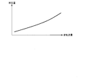
- the predetermined amount may be a fixed value or a variable value that is changed according to the exhaust gas flow rate. For example, the odor of NH 3 when exhaust gas is discharged into the atmosphere becomes stronger as the concentration of NH 3 contained in the exhaust gas becomes higher. Therefore, as shown in FIG. 5, the predetermined amount may be set to a smaller value as the exhaust flow rate decreases.
- the ECU 7 obtains the temperature of the SCR catalyst (Tstrg in FIG. 4) at which the adsorption capacity of the SCR catalyst becomes equal to the target capacity, and sets the temperature Tstrg as the target temperature of the SCR catalyst in the temperature raising process. At that time, as shown in FIG. 4, the correlation between the adsorption capacity of the SCR catalyst and the temperature of the SCR catalyst is experimentally obtained in advance. Next, the ECU 7 calculates the retard amount of the ignition timing and the advance amount of the opening timing of the exhaust valve based on the difference between the current temperature of the SCR catalyst (Tspt in FIG. 4) and the target temperature Tstrg. do it.
- the retard amount of the ignition timing and the advance amount of the exhaust valve opening timing may be fixed values determined in advance.
- the ECU 7 may end the temperature raising process when the temperature of the SCR catalyst reaches the target temperature Tstrg.
- the NH 3 adsorption amount of the SCR catalyst can be reduced without generating an irritating odor.
- the target air-fuel ratio of the air-fuel mixture when the temperature raising process is executed may be set to an air-fuel ratio determined according to the operating state of the internal combustion engine 1, but is set to the predetermined lean air-fuel ratio. May be.
- the target air-fuel ratio of the air-fuel mixture is set to the predetermined lean air-fuel ratio when the temperature raising process is executed, desorption of NH 3 adsorbed on the SCR catalyst is promoted and the SCR catalyst Oxidation of NH 3 adsorbed or NH 3 desorbed from the SCR catalyst is promoted.
- the amount of NH 3 adsorbed by the SCR catalyst can be rapidly reduced while suppressing the amount of NH 3 discharged into the atmosphere below the allowable amount.
- the air-fuel ratio of the air-fuel mixture at the time of executing the temperature raising process is set to the predetermined lean air-fuel ratio, the deterioration of the fuel consumption rate can be suppressed to a minimum.
- the temperature raising process be performed by a method of retarding the ignition timing of the internal combustion engine 1 or a method of advancing the valve opening timing of the exhaust valve of the internal combustion engine 1.
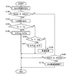
- FIG. 6 is a flowchart showing a processing routine executed by the ECU 7 when the NH 3 adsorption amount of the SCR catalyst is decreased.
- This processing routine is stored in advance in the ROM of the ECU 7, and is periodically executed by the ECU 7.
- the ECU 7 first reads the NH 3 adsorption amount Adnh3 of the SCR catalyst in the processing of S101.
- the NH 3 adsorption amount Adnh3 of the SCR catalyst is obtained by integrating the value obtained by subtracting the NH 3 consumption amount and the NH 3 slip amount from the total amount of NH 3 produced by the three-way catalyst and the NSR catalyst. Desired.
- the ECU 7 determines whether or not the NH 3 adsorption amount Adnh3 read in the process of S101 is equal to or greater than a predetermined threshold value Adthre1.
- a predetermined threshold Adthre1 as described above, when the adsorbed NH 3 amount of the SCR catalyst is the predetermined threshold value Adthre1 above, the internal combustion engine 1 in an easy operating condition NH 3 is desorbed adsorbed on the SCR catalyst
- the amount of NH 3 desorbed from the SCR catalyst and discharged into the atmosphere is an amount obtained by subtracting a predetermined margin from the amount of NH 3 adsorbed that is considered to exceed the allowable amount.
- the ECU 7 reads the temperature Ts of the SCR catalyst in the process of S103. Specifically, the ECU 7 reads the measured value of the temperature sensor 12 as the temperature Ts of the SCR catalyst. In addition, when the temperature sensor is also attached to the exhaust pipe 3 between the second catalyst casing 5 and the third catalyst casing 6, from the difference between the measured value of the temperature sensor and the measured value of the temperature sensor 12. The temperature Ts of the SCR catalyst may be calculated. By obtaining the temperature Ts of the SCR catalyst by these methods, the “detecting means” according to the present invention is realized.
- the ECU 7 determines whether or not the temperature Ts read in the process of S103 is lower than the lower limit temperature Tsl.
- the lower limit temperature Tsl is the lower limit value of the temperature at which NH 3 can be oxidized as described above. If an affirmative determination is made in the process of S104 (Ts ⁇ Tsl), the ECU 7 proceeds to the process of S105.
- the ECU 7 sets the target air-fuel ratio A / Ftrg of the air-fuel mixture to a predetermined weak lean air-fuel ratio A / Fsl.
- the predetermined weak lean air-fuel ratio A / Fsl is an air-fuel ratio at which the amount of NO x flowing out from the three-way catalyst is larger than zero as described in the description of FIG.
- the target air-fuel ratio A / Ftrg of the mixture is set to a predetermined slightly lean air-fuel ratio A / Fsl
- the exhaust gas flowing out of the NSR catalyst is to contain relatively large amounts of NO X.
- the amount of NH 3 contributing to the reduction of NO x in the SCR catalyst increases.
- the NH 3 adsorption amount Adnh3 of the SCR catalyst can be effectively reduced.
- the ECU 7 proceeds to the process of S106, and determines whether or not the temperature Ts read in the process of S103 is less than a predetermined temperature Tsm. To do. That is, the ECU 7 determines whether or not the temperature Ts of the SCR catalyst belongs to a temperature range equal to or higher than the lower limit temperature Tsl and lower than the predetermined temperature Tsm. As described above, the predetermined temperature Tsm is the minimum value of the temperature at which the amount of NH 3 desorbed from the SCR catalyst per unit time is larger than the amount of NH 3 oxidized per unit time in the SCR catalyst. It is. If an affirmative determination is made in the process of S106 (Ts ⁇ Tsm), the ECU 7 proceeds to the process of S107.
- the ECU 7 sets the target air-fuel ratio A / Ftrg of the air-fuel mixture to a predetermined lean air-fuel ratio A / Fl.
- the predetermined lean air-fuel ratio A / Fl is higher than the predetermined weak lean air-fuel ratio A / Fsl, and the combustion stability and drivability of the internal combustion engine 1 can be ensured.
- the highest air-fuel ratio within the air-fuel ratio range (or the highest air-fuel ratio within the range where exhaust emissions other than NH 3 do not exceed the regulation value).
- the predetermined lean air-fuel ratio A / Fl may be an air-fuel ratio determined according to the operating state of the internal combustion engine 1. Good.
- the target air-fuel ratio A / Ftrg of the air-fuel mixture is set to a predetermined lean air-fuel ratio A / Fl
- exhaust gas containing a relatively large amount of oxygen is supplied to the SCR catalyst.
- the NO X is produced by the reaction of NH 3 and oxygen adsorbed on the SCR catalyst, so that the NO X is reacted with NH 3 adsorbed by the SCR catalyst.
- the NH 3 adsorption amount Adnh3 of the SCR catalyst can be effectively reduced.
- the ECU 7 proceeds to the process of S108.
- the ECU 7 executes a temperature raising process. Specifically, the ECU 7 accelerates the temperature increase of the SCR catalyst by executing a process for retarding the ignition timing of the internal combustion engine 1 or a process for advancing the valve opening timing of the exhaust valve of the internal combustion engine 1. .
- the ECU 7 sets the target temperature of the SCR catalyst so that the amount of NH 3 desorbed from the SCR catalyst during the temperature raising process is kept below the predetermined amount. Tstrg is calculated.
- the ECU 7 performs a temperature raising process so that the temperature Ts of the SCR catalyst rises to the target temperature Tstrg.
- the NH 3 adsorption amount of the SCR catalyst can be reduced without generating an irritating odor.
- the ECU 7 may set the target air-fuel ratio of the air-fuel mixture to the predetermined lean air-fuel ratio when executing the temperature raising process.
- the target air-fuel ratio of the air-fuel mixture during the temperature raising process is set to the predetermined lean air-fuel ratio, desorption of NH 3 adsorbed on the SCR catalyst can be promoted and adsorbed on the SCR catalyst.
- the oxidation of NH 3 released from NH 3 and the SCR catalyst can be promoted.
- the ECU 7 finishes executing the process of S108, the ECU 7 once ends the execution of this process routine.
- the ECU 7 proceeds to the process of S109, and determines whether or not the NH 3 adsorption amount Adnh3 of the SCR catalyst read in the process of S101 is equal to or less than a predetermined end determination value Adthre2 that is smaller than the predetermined threshold Adthre1. .
- the ECU 7 If the NH 3 reduction process is being performed when the process of S110 is performed, the ECU 7 returns the target air-fuel ratio A / Ftrg of the air-fuel mixture to the air-fuel ratio corresponding to the operating state of the internal combustion engine 1. The NH 3 reduction process is terminated. If the NH 3 reduction process is not executed when the process of S110 is executed, the ECU 7 continues the non-execution state of the NH 3 reduction process.
- the “control means” according to the present invention is realized. Therefore, the NH 3 adsorption amount of the SCR catalyst can be decreased when the NH 3 adsorption amount of the SCR catalyst becomes equal to or greater than a predetermined threshold value. As a result, since the NH 3 adsorption amount of the SCR catalyst is suppressed from exceeding the predetermined threshold, the amount of NH 3 discharged from the SCR catalyst can be suppressed to the allowable amount or less.
- the air-fuel ratio of the air-fuel mixture is set to a predetermined lean air-fuel ratio higher than a predetermined weak lean air-fuel ratio. Since the amount of NH 3 adsorbed by the SCR catalyst is reduced by setting the fuel ratio, the opportunity for lowering the air-fuel ratio of the air-fuel mixture to a predetermined weak lean air-fuel ratio can be reduced. As a result, the amount of NH 3 discharged from the SCR catalyst can be suppressed to the allowable amount or less while suppressing the deterioration of the fuel consumption rate.
Landscapes
- Engineering & Computer Science (AREA)
- Chemical & Material Sciences (AREA)
- Chemical Kinetics & Catalysis (AREA)
- Combustion & Propulsion (AREA)
- Mechanical Engineering (AREA)
- General Engineering & Computer Science (AREA)
- Health & Medical Sciences (AREA)
- Toxicology (AREA)
- Exhaust Gas After Treatment (AREA)
Abstract
La présente invention concerne un dispositif de commande destiné à être utilisé dans des moteurs à combustion interne dans lequel un catalyseur NSR et un catalyseur SCR sont disposés dans un passage de gaz d'échappement, et qui résout le problème de réduction de la quantité de NH3 adsorbé sur le catalyseur SCR, tout en atténuant les détériorations du taux de consommation de carburant. À cet effet, la présente invention concerne un dispositif de commande destiné à être utilisé dans des moteurs à combustion interne, dans lequel un catalyseur NSR et un catalyseur SCR sont disposés dans un passage de gaz d'échappement, dans lequel, lorsqu'il est nécessaire de réduire la quantité de NH3 adsorbé sur le catalyseur SCR, si la température du catalyseur SCR est au moins égale à une température limite inférieure à laquelle l'oxydation du NH3 est possible, le rapport air-carburant du mélange air-carburant à brûler dans le moteur à combustion interne est réglé sur un rapport air-carburant faible prédéterminé qui est supérieur au rapport air-carburant stœchiométrique, et si la température du catalyseur SCR est inférieure à la température limite inférieure, le rapport air-carburant du mélange air-carburant à brûler dans le moteur à combustion interne est réglé sur un rapport air-carburant légèrement faible prédéterminé qui est inférieur au rapport air-carburant faible prédéterminé et supérieur au rapport air-carburant stœchiométrique.
Priority Applications (3)
| Application Number | Priority Date | Filing Date | Title |
|---|---|---|---|
| DE112016002413.4T DE112016002413T5 (de) | 2015-05-29 | 2016-05-25 | Steuereinrichtung für Verbrennungskraftmaschine |
| CN201680025506.5A CN107614843B (zh) | 2015-05-29 | 2016-05-25 | 内燃机的控制装置 |
| US15/577,391 US10415490B2 (en) | 2015-05-29 | 2016-05-25 | Control apparatus for internal combustion engine |
Applications Claiming Priority (4)
| Application Number | Priority Date | Filing Date | Title |
|---|---|---|---|
| JP2015-110164 | 2015-05-29 | ||
| JP2015110164 | 2015-05-29 | ||
| JP2016100368A JP6245309B2 (ja) | 2015-05-29 | 2016-05-19 | 内燃機関の制御装置 |
| JP2016-100368 | 2016-05-19 |
Publications (1)
| Publication Number | Publication Date |
|---|---|
| WO2016194735A1 true WO2016194735A1 (fr) | 2016-12-08 |
Family
ID=57441162
Family Applications (1)
| Application Number | Title | Priority Date | Filing Date |
|---|---|---|---|
| PCT/JP2016/065459 Ceased WO2016194735A1 (fr) | 2015-05-29 | 2016-05-25 | Dispositif de commande de moteur à combustion interne |
Country Status (1)
| Country | Link |
|---|---|
| WO (1) | WO2016194735A1 (fr) |
Cited By (5)
| Publication number | Priority date | Publication date | Assignee | Title |
|---|---|---|---|---|
| JP2018105233A (ja) * | 2016-12-27 | 2018-07-05 | トヨタ自動車株式会社 | 内燃機関の排気浄化装置 |
| JP2018105236A (ja) * | 2016-12-27 | 2018-07-05 | トヨタ自動車株式会社 | 内燃機関の排気浄化装置 |
| CN109973181A (zh) * | 2017-12-27 | 2019-07-05 | 丰田自动车株式会社 | 内燃机的排气净化装置 |
| CN109973180A (zh) * | 2017-12-27 | 2019-07-05 | 丰田自动车株式会社 | 内燃机的排气净化装置 |
| US10371029B2 (en) | 2016-12-09 | 2019-08-06 | Toyota Jidasha Kabushiki Kaisha | Exhaust gas control apparatus for internal combustion engine |
Citations (5)
| Publication number | Priority date | Publication date | Assignee | Title |
|---|---|---|---|---|
| JPH1047041A (ja) * | 1996-08-02 | 1998-02-17 | Toyota Motor Corp | 内燃機関の排気浄化装置 |
| JP2009257231A (ja) * | 2008-04-17 | 2009-11-05 | Toyota Motor Corp | 内燃機関の排気浄化装置 |
| JP2009257226A (ja) * | 2008-04-17 | 2009-11-05 | Toyota Motor Corp | 内燃機関の排気浄化装置 |
| JP2012082710A (ja) * | 2010-10-07 | 2012-04-26 | Toyota Motor Corp | Noxセンサの劣化検出システム |
| JP2012237296A (ja) * | 2011-05-13 | 2012-12-06 | Toyota Motor Corp | 内燃機関の制御装置 |
-
2016
- 2016-05-25 WO PCT/JP2016/065459 patent/WO2016194735A1/fr not_active Ceased
Patent Citations (5)
| Publication number | Priority date | Publication date | Assignee | Title |
|---|---|---|---|---|
| JPH1047041A (ja) * | 1996-08-02 | 1998-02-17 | Toyota Motor Corp | 内燃機関の排気浄化装置 |
| JP2009257231A (ja) * | 2008-04-17 | 2009-11-05 | Toyota Motor Corp | 内燃機関の排気浄化装置 |
| JP2009257226A (ja) * | 2008-04-17 | 2009-11-05 | Toyota Motor Corp | 内燃機関の排気浄化装置 |
| JP2012082710A (ja) * | 2010-10-07 | 2012-04-26 | Toyota Motor Corp | Noxセンサの劣化検出システム |
| JP2012237296A (ja) * | 2011-05-13 | 2012-12-06 | Toyota Motor Corp | 内燃機関の制御装置 |
Cited By (7)
| Publication number | Priority date | Publication date | Assignee | Title |
|---|---|---|---|---|
| US10371029B2 (en) | 2016-12-09 | 2019-08-06 | Toyota Jidasha Kabushiki Kaisha | Exhaust gas control apparatus for internal combustion engine |
| TWI672435B (zh) * | 2016-12-09 | 2019-09-21 | 日商豐田自動車股份有限公司 | 用於內燃機之排氣控制裝置 |
| JP2018105233A (ja) * | 2016-12-27 | 2018-07-05 | トヨタ自動車株式会社 | 内燃機関の排気浄化装置 |
| JP2018105236A (ja) * | 2016-12-27 | 2018-07-05 | トヨタ自動車株式会社 | 内燃機関の排気浄化装置 |
| CN109973181A (zh) * | 2017-12-27 | 2019-07-05 | 丰田自动车株式会社 | 内燃机的排气净化装置 |
| CN109973180A (zh) * | 2017-12-27 | 2019-07-05 | 丰田自动车株式会社 | 内燃机的排气净化装置 |
| CN109973181B (zh) * | 2017-12-27 | 2021-04-09 | 丰田自动车株式会社 | 内燃机的排气净化装置 |
Similar Documents
| Publication | Publication Date | Title |
|---|---|---|
| JP6245309B2 (ja) | 内燃機関の制御装置 | |
| JP6123822B2 (ja) | 排気浄化装置の劣化診断装置 | |
| US9416716B2 (en) | Control apparatus for an internal combustion engine | |
| JP6278039B2 (ja) | 選択還元型触媒の劣化診断装置 | |
| US20170306818A1 (en) | Control apparatus for exhaust gas purification apparatus | |
| JP6278005B2 (ja) | 排気浄化装置の劣化診断装置 | |
| US9611776B2 (en) | Deterioration diagnosis device for an exhaust gas purification apparatus | |
| WO2016194735A1 (fr) | Dispositif de commande de moteur à combustion interne | |
| JP2012031826A (ja) | 排気浄化装置の異常検出システム | |
| JP2008175173A (ja) | 空燃比制御装置 | |
| US10316776B2 (en) | Control apparatus for an internal combustion engine | |
| US10760461B2 (en) | Catalyst oxygen purge control apparatus and method | |
| JP2009150367A (ja) | 内燃機関の触媒劣化診断装置 | |
| JP5035670B2 (ja) | 内燃機関の触媒劣化検出装置 | |
| JP6248974B2 (ja) | 内燃機関の制御装置 | |
| JP2015014213A (ja) | 選択還元型触媒の劣化検出装置 | |
| JP7327329B2 (ja) | 触媒制御装置 | |
| KR101816424B1 (ko) | 질소산화물 정화 장치의 배출 가스 공연비 제어 방법 | |
| JP2005090460A (ja) | エンジンの制御装置 | |
| US9562486B2 (en) | Control device for internal combustion engine | |
| JP2014137043A (ja) | 火花点火式内燃機関の排気浄化装置 | |
| JP2007278246A (ja) | 内燃機関の排気浄化装置 |
Legal Events
| Date | Code | Title | Description |
|---|---|---|---|
| 121 | Ep: the epo has been informed by wipo that ep was designated in this application |
Ref document number: 16803170 Country of ref document: EP Kind code of ref document: A1 |
|
| WWE | Wipo information: entry into national phase |
Ref document number: 15577391 Country of ref document: US |
|
| WWE | Wipo information: entry into national phase |
Ref document number: 112016002413 Country of ref document: DE |
|
| 122 | Ep: pct application non-entry in european phase |
Ref document number: 16803170 Country of ref document: EP Kind code of ref document: A1 |