WO2016194808A1 - 内燃機関用摺動部材 - Google Patents
内燃機関用摺動部材 Download PDFInfo
- Publication number
- WO2016194808A1 WO2016194808A1 PCT/JP2016/065708 JP2016065708W WO2016194808A1 WO 2016194808 A1 WO2016194808 A1 WO 2016194808A1 JP 2016065708 W JP2016065708 W JP 2016065708W WO 2016194808 A1 WO2016194808 A1 WO 2016194808A1
- Authority
- WO
- WIPO (PCT)
- Prior art keywords
- washer
- bearing
- resin
- semi
- crank
- Prior art date
- Legal status (The legal status is an assumption and is not a legal conclusion. Google has not performed a legal analysis and makes no representation as to the accuracy of the status listed.)
- Ceased
Links
Images







Classifications
-
- F—MECHANICAL ENGINEERING; LIGHTING; HEATING; WEAPONS; BLASTING
- F16—ENGINEERING ELEMENTS AND UNITS; GENERAL MEASURES FOR PRODUCING AND MAINTAINING EFFECTIVE FUNCTIONING OF MACHINES OR INSTALLATIONS; THERMAL INSULATION IN GENERAL
- F16C—SHAFTS; FLEXIBLE SHAFTS; ELEMENTS OR CRANKSHAFT MECHANISMS; ROTARY BODIES OTHER THAN GEARING ELEMENTS; BEARINGS
- F16C9/00—Bearings for crankshafts or connecting-rods; Attachment of connecting-rods
- F16C9/04—Connecting-rod bearings; Attachments thereof
-
- F—MECHANICAL ENGINEERING; LIGHTING; HEATING; WEAPONS; BLASTING
- F01—MACHINES OR ENGINES IN GENERAL; ENGINE PLANTS IN GENERAL; STEAM ENGINES
- F01M—LUBRICATING OF MACHINES OR ENGINES IN GENERAL; LUBRICATING INTERNAL COMBUSTION ENGINES; CRANKCASE VENTILATING
- F01M1/00—Pressure lubrication
- F01M1/06—Lubricating systems characterised by the provision therein of crankshafts or connecting rods with lubricant passageways, e.g. bores
-
- F—MECHANICAL ENGINEERING; LIGHTING; HEATING; WEAPONS; BLASTING
- F16—ENGINEERING ELEMENTS AND UNITS; GENERAL MEASURES FOR PRODUCING AND MAINTAINING EFFECTIVE FUNCTIONING OF MACHINES OR INSTALLATIONS; THERMAL INSULATION IN GENERAL
- F16C—SHAFTS; FLEXIBLE SHAFTS; ELEMENTS OR CRANKSHAFT MECHANISMS; ROTARY BODIES OTHER THAN GEARING ELEMENTS; BEARINGS
- F16C17/00—Sliding-contact bearings for exclusively rotary movement
- F16C17/10—Sliding-contact bearings for exclusively rotary movement for both radial and axial load
-
- F—MECHANICAL ENGINEERING; LIGHTING; HEATING; WEAPONS; BLASTING
- F16—ENGINEERING ELEMENTS AND UNITS; GENERAL MEASURES FOR PRODUCING AND MAINTAINING EFFECTIVE FUNCTIONING OF MACHINES OR INSTALLATIONS; THERMAL INSULATION IN GENERAL
- F16C—SHAFTS; FLEXIBLE SHAFTS; ELEMENTS OR CRANKSHAFT MECHANISMS; ROTARY BODIES OTHER THAN GEARING ELEMENTS; BEARINGS
- F16C33/00—Parts of bearings; Special methods for making bearings or parts thereof
- F16C33/02—Parts of sliding-contact bearings
- F16C33/04—Brasses; Bushes; Linings
- F16C33/20—Sliding surface consisting mainly of plastics
- F16C33/208—Methods of manufacture, e.g. shaping, applying coatings
-
- F—MECHANICAL ENGINEERING; LIGHTING; HEATING; WEAPONS; BLASTING
- F16—ENGINEERING ELEMENTS AND UNITS; GENERAL MEASURES FOR PRODUCING AND MAINTAINING EFFECTIVE FUNCTIONING OF MACHINES OR INSTALLATIONS; THERMAL INSULATION IN GENERAL
- F16C—SHAFTS; FLEXIBLE SHAFTS; ELEMENTS OR CRANKSHAFT MECHANISMS; ROTARY BODIES OTHER THAN GEARING ELEMENTS; BEARINGS
- F16C9/00—Bearings for crankshafts or connecting-rods; Attachment of connecting-rods
- F16C9/02—Crankshaft bearings
-
- F—MECHANICAL ENGINEERING; LIGHTING; HEATING; WEAPONS; BLASTING
- F16—ENGINEERING ELEMENTS AND UNITS; GENERAL MEASURES FOR PRODUCING AND MAINTAINING EFFECTIVE FUNCTIONING OF MACHINES OR INSTALLATIONS; THERMAL INSULATION IN GENERAL
- F16C—SHAFTS; FLEXIBLE SHAFTS; ELEMENTS OR CRANKSHAFT MECHANISMS; ROTARY BODIES OTHER THAN GEARING ELEMENTS; BEARINGS
- F16C17/00—Sliding-contact bearings for exclusively rotary movement
- F16C17/02—Sliding-contact bearings for exclusively rotary movement for radial load only
- F16C17/022—Sliding-contact bearings for exclusively rotary movement for radial load only with a pair of essentially semicircular bearing sleeves
-
- F—MECHANICAL ENGINEERING; LIGHTING; HEATING; WEAPONS; BLASTING
- F16—ENGINEERING ELEMENTS AND UNITS; GENERAL MEASURES FOR PRODUCING AND MAINTAINING EFFECTIVE FUNCTIONING OF MACHINES OR INSTALLATIONS; THERMAL INSULATION IN GENERAL
- F16C—SHAFTS; FLEXIBLE SHAFTS; ELEMENTS OR CRANKSHAFT MECHANISMS; ROTARY BODIES OTHER THAN GEARING ELEMENTS; BEARINGS
- F16C17/00—Sliding-contact bearings for exclusively rotary movement
- F16C17/04—Sliding-contact bearings for exclusively rotary movement for axial load only
-
- F—MECHANICAL ENGINEERING; LIGHTING; HEATING; WEAPONS; BLASTING
- F16—ENGINEERING ELEMENTS AND UNITS; GENERAL MEASURES FOR PRODUCING AND MAINTAINING EFFECTIVE FUNCTIONING OF MACHINES OR INSTALLATIONS; THERMAL INSULATION IN GENERAL
- F16C—SHAFTS; FLEXIBLE SHAFTS; ELEMENTS OR CRANKSHAFT MECHANISMS; ROTARY BODIES OTHER THAN GEARING ELEMENTS; BEARINGS
- F16C33/00—Parts of bearings; Special methods for making bearings or parts thereof
- F16C33/02—Parts of sliding-contact bearings
- F16C33/04—Brasses; Bushes; Linings
- F16C33/20—Sliding surface consisting mainly of plastics
- F16C33/201—Composition of the plastic
Definitions
- the present invention relates to a sliding member used in an internal combustion engine such as an automobile.
- a bimetal having a lining layer formed of a copper-based or aluminum-based bearing alloy on a back metal formed of steel or the like is used.
- a bearing is known (for example, Patent Document 1).
- bearings made of resin are known as bearings that are not used for internal combustion engines but are used in office equipment and the like (for example, Patent Documents 2 and 3).
- a thrust washer described in Patent Document 4 is known.
- JP 2013-167280 A Japanese Patent Laid-Open No. 2008-19880 JP 2000-87954 A Japanese Patent Laid-Open No. 2004-19800
- the present invention relates to a technique for improving warm-up characteristics in a sliding member for an internal combustion engine.
- One aspect of the present invention is a bearing body formed of resin in a semi-cylindrical shape or a cylindrical shape having an inner peripheral surface that slides with a mating shaft and an outer peripheral surface that contacts a housing, and a semi-annular resin that is formed of resin.
- a sliding member for an internal combustion engine having a first washer provided at one axial end of a main body and having a first thrust surface for receiving the axial load.
- the first washer may be formed integrally with the bearing body.
- the first washer may be fixed to the bearing body.
- the first washer may be assembled to be movable relative to the bearing body.
- the sliding member for an internal combustion engine may include a second washer provided at the other end of the bearing body and having a second thrust surface that receives the axial load.
- This sliding member for an internal combustion engine may have an oil groove formed on the first thrust surface.
- the present invention provides a washer formed of resin in a semi-annular shape, and a bearing body formed of resin in a semi-cylindrical shape or a cylindrical shape having an inner peripheral surface that slides with a counterpart shaft and an outer peripheral surface that contacts a housing.
- a sliding member for an internal combustion engine having a washer sandwiched from both ends in the axial direction of the mating shaft and sliding against the mating shaft by a sliding surface provided on the opposite side of the bearing body to support the axial force I will provide a.
- the present invention is a portion formed of resin in a semi-cylindrical shape or a cylindrical shape having an inner peripheral surface that slides with the counterpart shaft and an outer peripheral surface that contacts the housing, and projects in a radial direction at both ends in the axial direction of the counterpart shaft.
- a sliding member for an internal combustion engine having a flange bearing provided with a flange portion having a sliding surface that slides with the counterpart shaft.
- the present invention provides a bearing body formed of resin in a semi-cylindrical shape having two washers formed of resin in a semi-annular shape, an inner peripheral surface that slides with a mating shaft, and an outer peripheral surface that contacts the housing;
- the bearing body is sandwiched between the two washers from both axial ends of the mating shaft and is assembled so as to be relatively movable.
- the washer is opposite to the bearing body.
- a sliding member for an internal combustion engine characterized in that a sliding surface is provided on the side, and the sliding surface supports the axial force by sliding with the counterpart shaft.
- the oil sliding groove may be formed on the sliding surface.
- warm-up characteristics can be improved in a sliding member for an internal combustion engine.
- the figure which illustrates the crankshaft 1 in an internal combustion engine The figure which illustrates the external appearance of the main bearing 10
- the figure which illustrates the external appearance of the semi-cylindrical bearing 11 The figure which illustrates the cross-section of semi-cylindrical bearing 11 Figure illustrating a classic relief
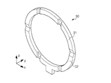
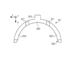
- the figure which illustrates the external appearance of the crank washer 30 The figure which illustrates the lower washer 32 which comprises the crank washer 30
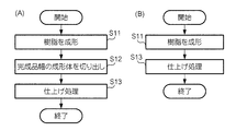
- Flowchart showing a manufacturing method according to Example 2 of the bearing The figure which illustrates the manufacturing process concerning Example 2 Flow chart showing how to mold resin by papermaking Flowchart showing a manufacturing method according to bearing example 3
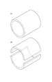
- the figure which illustrates the manufacturing process concerning Example 3 The figure which shows the connection member with which the upper washer 31 was connected with the semi-cylindrical bearing 11.
- FIG. 1 is a diagram illustrating a crankshaft 1 in an internal combustion engine.
- a main bearing 10 a connecting rod bearing 20, and a crank washer 30 are used.
- the main bearing 10 is a bearing that is mounted on a housing (not shown) of a cylinder block (not shown), holds a journal of the crankshaft 1, and supports the crankshaft 1.
- the connecting rod bearing 20 is a bearing that is attached to the connecting rod 2 to hold the pin of the crankshaft 1 and supports the connecting rod 2.
- the crank washer 30 is a bearing that is used in combination with the main bearing 10 and supports the axial force of the crankshaft 1.
- the crank washer 30 also has a function of positioning the crankshaft 1 and the cylinder block in the axial direction.
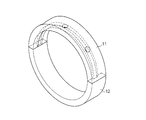
- FIG. 2 is a diagram illustrating the external appearance of the main bearing 10.
- the main bearing 10 is composed of two semi-cylindrical bearings (a semi-cylindrical bearing 11 and a semi-cylindrical bearing 12).
- the semi-cylindrical bearing 11 is a bearing (upper bearing) mounted on the piston side as viewed from the crankshaft 1
- the semi-cylindrical bearing 12 is a bearing (lower bearing) mounted on the opposite side.
- the semi-cylindrical bearing 11 and the semi-cylindrical bearing 12 are examples of a bearing for an internal combustion engine according to the present invention.
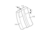
- FIG. 3 is a diagram illustrating the external appearance of the semi-cylindrical bearing 11.
- the semi-cylindrical bearing 11 has a bearing body 111.
- the bearing body 111 is entirely made of resin.
- the resin a thermosetting resin or a thermoplastic resin is used.
- thermosetting resin examples include thermosetting polyimide resin (PI), phenol resin (PF), urea resin (UF), melamine resin (MF), epoxy resin (EP), furan resin (FF), and xylene resin.
- PI thermosetting polyimide resin
- PF phenol resin
- UF urea resin
- MF melamine resin
- EP epoxy resin
- FF furan resin
- xylene resin examples include thermosetting polyimide resin (PI), phenol resin (PF), urea resin (UF), melamine resin (MF), epoxy resin (EP), furan resin (FF), and xylene resin.
- XF alkyd resin
- UP silicon resin
- SI allyl resin
- FRP fiber reinforced plastic
- thermoplastic resin examples include polyvinyl chloride resin (PVC), polyvinylidene chloride resin (PVdC), polyvinyl alcohol resin (PVA), polystyrene resin (PS), acrylonitrile / styrene resin (AS), acrylonitrile / butadiene / styrene.
- ABS polyethylene resin
- PE polyethylene / vinyl acetate copolymer resin
- EVA polypropylene resin
- POM polyacetal resin
- PMMA polymethyl methacrylate resin
- MS acetic acid Cellulose resin
- PC polycarbonate resin
- PA polyamide resin
- PA polyurethane resin
- PU fluororesin
- PTFE fluororesin
- FEP FEP, PFA, etc.
- PAI Polya Doimide resin
- PPS polyphenylene sulfide
- PEEK polyetheretherketone
- TPI thermoplastic polyimide
- PBI polybenzimidazole
- PEI polyetherimide resin
- PSF polysulfone resin
- PES polyarylate resin
- PAR polyarylate resin
- the heat resistant temperature (for example, continuous use temperature) of the resin is preferably 180 ° C. or higher, and more preferably 200 ° C. or higher.
- the thermal conductivity of the resin is preferably 1 W / mK or less, and more preferably 0.5 W / mK or less.
- the water absorption rate of resin is 0.2% or less.
- a thermoplastic resin has a problem that the glass transition point is lowered by water absorption, and therefore, the water absorption is preferably 0.2% or less.
- the linear expansion coefficient of the resin is preferably 70 ⁇ 10 ⁇ 6 or less.
- the bearing body 111 When the bearing body 111 is entirely made of resin, the heat of the lubricating oil is less likely to escape to the housing via the bearing compared to an example in which the bearing body is made of metal, and the engine is cold started The temperature rising rate of the lubricating oil can be improved.
- the bearing body 111 is formed in a semi-cylindrical shape, and has an inner peripheral surface 112 (sliding surface) that slides with the crankshaft 1 and an outer peripheral surface 113 that contacts a housing (not shown).
- the diameter of the crankshaft 1 is, for example, ⁇ 30 to 150 mm, and the bearing body 111 has an inner diameter that matches the diameter of the crankshaft 1. Further, the bearing body 111 has a mating surface 114 and a mating surface 115 that are in contact with the semi-cylindrical bearing 12.
- the semi-cylindrical bearing 11 has an oil groove 116 on the inner peripheral surface 112.
- the oil groove 116 is a groove for supplying lubricating oil to the sliding surface and holding the supplied lubricating oil.
- the oil groove 116 is provided with at least one oil hole 117 penetrating from the outer peripheral surface 113 to the inner peripheral surface 112.
- An oil hole (not shown) is provided in a portion of the crankshaft 1 supported by the semi-cylindrical bearing 11 at a position facing the oil groove 116. This oil hole penetrates to a portion of the crankshaft 1 supported by the connecting rod bearing 20.
- Lubricating oil is supplied to the outer peripheral surface 113 of the semi-cylindrical bearing 11 through an oil passage (not shown) provided in the cylinder block.
- the lubricating oil supplied to the outer peripheral surface 113 is supplied to the inner peripheral surface 112 (sliding surface) through the oil hole 117, and lubricates the main bearing.
- the lubricating oil on the sliding surface is supplied to the sliding surface of the connecting rod bearing 20 through the oil hole of the crankshaft 1.
- FIG. 4 is a diagram illustrating a cross-sectional structure of the semi-cylindrical bearing 11.
- FIG. 4A is an external view of the semi-cylindrical bearing 11 viewed from a direction perpendicular to the mating surface.
- FIG. 4B is a cross-sectional view taken along the line BB in FIG.
- This cross section is a cross section perpendicular to the axial direction (a cross section parallel to the sliding direction).
- the thickness of the bearing body 111 is not uniform, and is thicker toward the center, and becomes thinner from the center toward the end (mating surface).
- the oil relief refers to a gap on the inner peripheral surface with respect to a circle (a circle passing through the central portion of the inner peripheral surface) based on the central portion of the inner peripheral surface of the semicylindrical bearing.
- the depth (amount) of the oil relief is measured on the basis of a predetermined height (for example, 6 to 13 mm) from the mating surface, and is, for example, 0.005 to 0.025 mm.
- Oil relief expands the oil clearance near the mating surface and helps create wedge film pressure. Furthermore, the oil relief helps to form an oil film, increases the amount of oil, and cools the bearing.
- the oil groove 116 is formed over the entire length in the sliding direction from the mating surface 114 to the mating surface 115.
- the depth of the oil groove is not uniform, and is deeper in the center of the bearing body 111 and becomes shallower from the center toward the mating surface.
- the bearing body 111 is provided with a crash relief.
- crash relief refers to a relief provided for the entire width of the bearing body 111 at a portion of the inner peripheral surface 112 that is in contact with the mating surface 114 and the mating surface 115.
- FIG. 5 is a diagram illustrating a crush relief.
- the crush relief is shown exaggerated rather than actual.
- the difference in position between the inner peripheral surface 112 and the circle drawn by the portion of the inner peripheral surface 112 other than the crash relief at the mating surface is referred to as the depth d of the crash relief, and the crash relief of the inner peripheral surface 112 is formed.
- the length of the portion that is made is called the length L of the crash relief.
- the depth d of the crash relief is, for example, 0.01 to 0.06 mm
- the length L of the crash relief is, for example, 4 to 9.5 mm.
- the crash relief prevents contact with the shaft even when the inner peripheral surface 112 in the vicinity of the mating surface is slightly tilted toward the mating shaft when the bearing is assembled to the housing.
- the crush relief has the effect of discharging the lubricating oil in the vicinity of the mating surface, cooling the bearing, and discharging foreign matter that has entered the sliding surface.
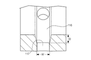
- FIG. 6 is a diagram illustrating a cross-sectional structure of the oil groove 116 and the oil hole 117.
- FIG. 6 shows a cross section perpendicular to the sliding direction (cross section parallel to the axial direction).
- the oil groove 116 has a trapezoidal shape with a narrow bottom and a wide opening.
- the bottom width W of the oil groove 116 is, for example, 2 to 5 mm, and the depth d of the oil groove 116 is smaller than the bottom width W, for example, 0.5 to 1 mm.
- a portion of the inner peripheral surface 112 other than the oil groove 116 is formed with a fine groove (micro groove) that is finer than the oil groove 116.
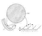
- FIG. 7 is a diagram illustrating a fine groove 118 formed on the inner peripheral surface 112.
- the fine grooves 118 are formed by regularly arranging grooves having an arc shape in cross section.
- the top part between two adjacent grooves is not flat but has a sharp shape.
- the interval between two adjacent apexes is referred to as pitch P
- the depth of the groove with reference to the apex is referred to as depth h.
- the pitch P of the fine groove 118 is larger than the depth h.
- the depth h is preferably 1 to 20 ⁇ m, for example, and more preferably 1 to 6 ⁇ m.
- the pitch P is preferably 0.1 to 0.4 mm, and more preferably 0.1 to 0.2 mm.
- the fine grooves 118 approach between the unlubricated state and the fluid lubricated state in the so-called Stribeck diagram, ensuring the fluid lubricated state at an early stage, and improving the conformability and oil retention.
- the bearing body 111 has an interference (so-called crash). That is, the diameter of the bearing body 111 is longer than the semicircle.
- the semi-cylindrical bearing 11 has a claw 119 on the outer peripheral surface 113.
- the claw 119 is an example of a convex portion that serves as a detent for preventing the semicylindrical bearing 11 from rotating relative to the housing. Further, the claw 119 has a function of preventing erroneous assembly and positioning in the circumferential direction and the axial direction.
- the semi-cylindrical bearing 11 has a so-called tension.
- tension means that the outer diameter dimension in a free state (not assembled to the housing) when viewed from the axial direction is larger than the inner diameter of the housing.
- the tension is, for example, 0.8 to 1.3 mm.
- the tension has the effect of allowing the outer periphery of the semi-cylindrical bearing 11 to conform to the inner periphery of the housing during assembly, and the effect of preventing the semi-cylindrical bearing 11 from moving or dropping from the housing during assembly. .
- the semi-cylindrical bearing 12 is omitted, but it is the same as the semi-cylindrical bearing 11 except that it does not have oil grooves and oil holes.
- the detailed description of the connecting rod bearing 20 is also omitted, it is the same as the main bearing 10 in that two semi-cylindrical bearings are used in combination. However, in the connecting rod bearing 20, neither of the two semi-cylindrical bearings has oil grooves and oil holes.
- the two semi-cylindrical bearings of the connecting rod bearing 20 are another example of the internal combustion engine bearing according to the present invention.
- FIG. 8 is a diagram illustrating the external appearance of the crank washer 30.
- FIG. 9 is a diagram illustrating a lower washer 32 (described later) constituting the crank washer 30.
- the space in which the crank washer 30 is arranged is represented as an xyz right-handed coordinate space.
- a symbol depicting two lines intersecting in a circle represents an arrow from the front side to the back side of the page.
- a direction along the x-axis in space is referred to as an x-axis direction.
- the direction in which the x component increases is called the + x direction
- the direction in which the x component decreases is called the -x direction.
- the y-axis direction, + y direction, -y direction, z-axis direction, + z direction, and -z direction are defined according to the above definition.
- the crank washer 30 is an annular flat plate having a portion projecting downward.
- the crank washer 30 is divided into an upper washer 31 and a lower washer 32 on a plane passing through the center of the ring.
- the crank washers 30 are a set of two, and the opposite surfaces of the sliding surfaces 320 (described later) face each other, and a housing (not shown) is sandwiched between them.
- the upper washer 31 (or lower washer 32) of one crank washer 30 is an example of the first washer among the set of crank washers 30, and the upper washer 31 (or lower washer 32) of the other crank washer 30 is the first. It is an example of 2 washers.
- the lower washer 32 has the same configuration as the upper washer 31 except that the lower washer 32 has a detent 323.
- the detent 323 engages with a detent groove provided in a housing (not shown) to prevent the lower washer 32 from rotating as the crankshaft 1 rotates. Further, the rotation of the lower washer 32 is suppressed by engaging the rotation stopper 323 with the rotation prevention groove of the housing, whereby the rotation of the upper washer 31 is also suppressed.
- a “relief” may be provided at the base of the detent 323 to prevent interference with the detent groove.
- the lower washer 32 has a sliding surface 320, an oil groove 321, and a mating surface relief 322 in addition to the detent 323.
- the mating surface relief 322 is for preventing the mating surfaces of the lower washer 32 and the upper washer 31 from coming into contact with the shaft during assembly.
- the mating surface relief 322 is provided in a radial direction from the axis of the crankshaft 1 and reduced in thickness in the + x direction and the ⁇ x direction, respectively, and in the + y direction as shown in FIGS. May be provided with reduced thickness.
- the sliding surface 320 is a surface that slides with the crankshaft 1 and is a portion (thrust surface) that receives the thrust load and supports the crankshaft 1.
- the sliding surface of the upper washer 31 or the lower washer 32 corresponding to the first washer is an example of the first thrust surface
- the sliding surface of the upper washer 31 or the lower washer 32 corresponding to the second washer is the second thrust surface. It is an example.
- the sliding surface 320 may be provided with the fine grooves shown in FIG.
- the oil groove 321 functions as a passage for lubricating oil supplied to the sliding surface 320.
- the upper washer 31 has the same structure as the lower washer 32 except that the upper washer 31 does not have a detent corresponding to the detent 323 of the lower washer 32.
- both the upper washer 31 and the lower washer 32 are all made of resin. Therefore, compared to the example in which the crank washer is made of metal, the heat of the lubricating oil is less likely to escape to the housing via the crank washer, and the temperature rise rate of the lubricating oil when the engine is cold started is improved. Can do.
- sliding members such as bearings and crank washers are formed one by one by injection molding or compression molding.
- the oil groove, oil hole, and fine groove may be formed by embedding the oil groove, oil hole, and fine groove in the mold. It may also be formed by cutting or the like in a shape formed into a ring or the like.
- FIG. 10 is a flowchart illustrating a manufacturing method according to the second example of the sliding member
- FIG. 11 is a diagram illustrating a manufacturing process.
- step S11 shown in FIG. 10A the resin is molded into a predetermined shape such as a semi-cylindrical shape or an annular shape.
- FIG. 11A illustrates the resin molded body formed into a semicylindrical shape in step S11.
- the semi-cylindrical shape here means a shape in which the axial length is longer than the width of the finished bearing. This molding is performed by injection molding or compression molding.
- step S12 shown in FIG. 10A a molded product having a width of the finished product is cut out from the resin molded product.
- FIG. 11B illustrates the cut-out molded body.
- step S13 shown in FIG. 10 (A) a necessary finishing process or the like is performed on each molded body.
- the finishing treatment here includes, for example, formation of oil grooves, formation of oil holes, formation of fine grooves, and chamfering.
- step S11 if resin is shape
- the flowchart showing the manufacturing method of the sliding member is shown in FIG.
- the resin is injection-molded, if a mold having an internal space designed for the size of the finished product is used, there is no need to cut out after molding.
- the upper washer 31 or the lower washer 32 constituting the crank washer 30 is formed, in step S11, if the resin is formed in an annular shape (referred to as a semi-annular shape) divided in half instead of an annular shape, a step is performed.
- the resin molded body may not be divided in half.
- the molding in step S11 may be performed by papermaking in addition to injection molding or compression molding.
- paper making means a step of producing a slurry by stirring a material containing a resin in water, a step of dehydrating the produced slurry, and pressurizing and heating the dehydrated slurry in a mold. And forming the solid member.
- FIG. 12 is a flowchart showing a method of molding a resin by papermaking.
- a material containing resin is blended.
- this material includes, for example, glass fibers, carbon fibers, inorganic fibers, inorganic fillers, friction modifiers, and the like.
- step S102 the above-described materials are put into water, stirred and mixed to produce a slurry.
- step S103 the slurry described above is supplied to the filter and dehydrated.
- suction filtration, pressure filtration, or the like is applied.
- step S104 the slurry after dehydration described above is supplied into the mold, and is pressed and heated to be molded into a predetermined shape such as a semi-cylindrical shape or an annular shape.
- the material is easily dispersed more uniformly than when other processes are applied. Moreover, when the fiber is contained in the material, since the fiber is difficult to be oriented in a specific direction, the strength of the resin molded body can be imparted and the strength can be improved.
- FIG. 13 is a flowchart illustrating a manufacturing method according to Example 3 of the bearing
- FIG. 14 is a diagram illustrating a manufacturing process.
- step S21 the resin is molded into a cylindrical shape.
- FIG. 14A illustrates the resin molded body molded in step S21.
- the cylindrical shape here refers to a shape in which the axial length is longer than the width of the finished bearing. This molding is performed by injection molding or compression molding.
- step S22 the cylindrical resin molded body is cut in the axial direction and divided into two. Two semi-cylindrical resin molded bodies can be formed.
- FIG. 14B illustrates the resin molded body divided in step S22.
- the process (step S23) and the finishing process (step S24) of cutting the molded product having the width of the finished bearing product from the semi-cylindrical resin molded body are the same as steps S12 and S13.
- step S23 shown in FIG. 13 may be omitted if the resin is formed into a cylindrical shape having the width of the finished bearing product in step S21 of FIG.
- step S21 in FIG. 13 may be performed by papermaking in the same manner as in Example 2.
- the specific shape of the bearing is not limited to that exemplified in the embodiment.
- at least one of an oil groove, an oil hole, a fine groove, an oil relief, a crash relief, a mating surface relief, a rotation stopper, and a claw may be omitted.
- at least one of an oil groove and an oil hole may be provided in the semi-cylindrical bearing 12 and the connecting rod bearing 20, at least one of an oil groove and an oil hole may be provided.
- the specific sizes of these elements are not limited to those exemplified in the embodiment.
- the specific shape, number, and position of the oil grooves and oil holes are not limited to those exemplified in the embodiment.
- the semi-cylindrical bearing may not have tension.
- the oil groove 116 communicates from the mating surface 114 to the mating surface 115 .
- the oil groove may be formed only in a part of the circumferential direction.
- the oil groove is not limited to the one formed on the sliding surface (inner peripheral surface), and may be formed on the outer peripheral surface. That is, the oil groove may be formed on at least one of the inner peripheral surface and the outer peripheral surface of the bearing body.
- crank washer 30 may be assembled with the main bearing 10 sandwiched therebetween.
- the crank washer 30 may be fixed to the main bearing 10 or may be connected to be relatively movable.
- the assembled crank washer 30 and the main bearing 10 may both be formed of resin, but either one may be formed of resin.
- FIG. 15 is a view showing a connecting member in which the lower washer 32 is connected to the semi-cylindrical bearing 12 so as to be relatively movable.
- the lower washer 32 is provided with a sliding surface 320, an oil groove 321, a mating surface relief 322, and claws 324 are provided at a plurality of locations.
- the semi-cylindrical bearing 11 is provided with a plurality of notches 120 at positions facing the claws 324.
- the lower washer 32 is assembled to the semi-cylindrical bearing 12 by caulking and engaging the notch 324 with the notch 120.
- the semi-cylindrical bearing 12 may be provided with notches 130 at both axial ends. In this case, the two upper washers 32 may be assembled by sandwiching the semi-cylindrical bearing 12 from both ends in the axial direction.
- the notch 120 may have an opening narrower than the claw 324 and an inner space wider than the claw 324.
- the claw 324 when engaged with the notch 120, the claw 324 is constrained by the opening and coupled so as to be relatively movable within the range of the internal space of the notch 120. This configuration absorbs assembly tolerances.
- FIG. 16 is a schematic view showing the appearance of this flange bearing.
- all the flange bearings may be made of resin.
Landscapes
- Engineering & Computer Science (AREA)
- General Engineering & Computer Science (AREA)
- Mechanical Engineering (AREA)
- Manufacturing & Machinery (AREA)
- Sliding-Contact Bearings (AREA)
- Shafts, Cranks, Connecting Bars, And Related Bearings (AREA)
- Lubrication Of Internal Combustion Engines (AREA)
Abstract
クランクワッシャ30は、下方側に突出した部位を有する環状の平板であり、環の中心を通る面で上部ワッシャ31と下部ワッシャ32とに分かれている。クランクワッシャ30は2枚で一組であり、それぞれの摺動面の反対側の面同士を向かい合わせ、間に主軸受を挟んで組付けられる。下部ワッシャ32は回り止めを有する点を除いて、上部ワッシャ31と共通の構成を有する。回り止めは、ハウジングに設けられた回り止め溝と係り合って下部ワッシャ32がクランクシャフトの回転に伴って回ることを防ぐ。合わせ面逃しは、組付け時に下部ワッシャ32および上部ワッシャ31の合わせ面が軸と接触することを防ぐ。摺動面320は、クランクシャフトと摺動する面であり、スラスト荷重を受けてクランクシャフトを支持する。クランクワッシャ30は、すべて樹脂で形成されている。
Description
本発明は、自動車等の内燃機関において用いられる摺動部材に関する。
自動車等の内燃機関(エンジン)において用いられる、いわゆる主軸受またはコンロッド軸受としては、鋼等で形成された裏金上に銅系またはアルミニウム系の軸受合金で形成されたライニング層を有するバイメタルを用いた軸受が知られている(例えば特許文献1)。また、内燃機関用ではないが、事務機器等において用いられる軸受としては、樹脂で形成した軸受が知られている(例えば特許文献2および3)。また、内燃機関用の摺動部材としては、例えば特許文献4に記載されたスラストワッシャなどが知られている。
自動車の内燃機関に要求される特性の一つに、冷間起動時の潤滑油昇温速度を高めること、いわゆる高い暖機特性の向上がある。しかし、特許文献1記載のように金属で形成された軸受を用いると、熱伝導率が比較的高いため潤滑油の熱が軸受を介して逃げてしまい、潤滑油の温度が上がりにくいという問題があった。特許文献2および3に記載の軸受は事務機器等、無潤滑の環境で用いられるものであり、潤滑油とともに用いられる内燃機関用軸受としては用いることができないという問題があった。
これに対し本発明は、内燃機関用の摺動部材において暖機特性を改善する技術に関する。
本発明の一態様は、相手軸と摺動する内周面およびハウジングと接する外周面を有する半円筒形状または円筒形状に樹脂で形成された軸受本体と、半環状に樹脂で形成され、前記軸受本体の軸方向の一端に設けられ、前記軸方向の荷重を受ける第1スラスト面を有する第1ワッシャとを有する内燃機関用摺動部材を提供する。
前記第1ワッシャが、前記軸受本体と一体で形成されていてもよい。
前記第1ワッシャが、前記軸受本体に対し固定されていてもよい。
前記第1ワッシャが、前記軸受本体に対し相対的に移動可能に組付けられていてもよい。
この内燃機関用摺動部材は、前記軸受本体の他端に設けられ、前記軸方向の荷重を受ける第2スラスト面を有する第2ワッシャを有してもよい。
この内燃機関用摺動部材は、前記第1スラスト面に形成された油溝を有してもよい。
本発明は、半環状に樹脂で形成されたワッシャであって、相手軸と摺動する内周面およびハウジングと接する外周面を有する半円筒形状または円筒形状に樹脂で形成された軸受本体を該相手軸の軸方向の両端側から挟み、該軸受本体の反対側に設けられた摺動面により該相手軸と摺動して前記軸方向の力を支えるワッシャ、を有する内燃機関用摺動部材を提供する。
また本発明は、相手軸と摺動する内周面およびハウジングと接する外周面を有する半円筒形状または円筒形状に樹脂で形成され、該相手軸の軸方向の両端において放射方向に突出した部位であって該相手軸と摺動する摺動面を有するフランジ部が設けられたフランジベアリング、を有する内燃機関用摺動部材を提供する。
また、本発明は、半環状に樹脂で形成された2枚のワッシャと、相手軸と摺動する内周面およびハウジングと接する外周面を有する半円筒形状に樹脂で形成された軸受本体と、を有し、前記軸受本体は、前記2枚のワッシャに前記相手軸の軸方向の両端側からそれぞれ挟まれて、かつ相対的に移動可能に組付けられ、前記ワッシャは、前記軸受本体の反対側に摺動面が設けられ、該摺動面により前記相手軸と摺動して前記軸方向の力を支えることを特徴とする内燃機関用摺動部材を提供する。
前記摺動面は、油溝が形成されていてもよい。
本発明によれば、内燃機関用の摺動部材において暖機特性を改善することができる。
1…クランクシャフト
2…コネクティングロッド
10…主軸受
11…半円筒型軸受
110…切欠き
111…軸受本体
1111…補強層
1112…樹脂層
112…内周面
113…外周面
114…合せ面
115…合せ面
116…油溝
117…油孔
118…微細溝
119…爪
12…半円筒型軸受
20…コンロッド軸受
30…クランクワッシャ
31…上部ワッシャ
32…下部ワッシャ
320…摺動面
321…油溝
322…合わせ面逃し
323…回り止め
324…爪
2…コネクティングロッド
10…主軸受
11…半円筒型軸受
110…切欠き
111…軸受本体
1111…補強層
1112…樹脂層
112…内周面
113…外周面
114…合せ面
115…合せ面
116…油溝
117…油孔
118…微細溝
119…爪
12…半円筒型軸受
20…コンロッド軸受
30…クランクワッシャ
31…上部ワッシャ
32…下部ワッシャ
320…摺動面
321…油溝
322…合わせ面逃し
323…回り止め
324…爪
1.構造
図1は、内燃機関におけるクランクシャフト1を例示する図である。クランクシャフト1においては、主軸受10、コンロッド軸受20、およびクランクワッシャ30が用いられる。主軸受10は、シリンダブロック(図示略)のハウジング(図示略)に装着してクランクシャフト1のジャーナルを把持し、クランクシャフト1を支える軸受である。コンロッド軸受20は、コネクティングロッド2に装着してクランクシャフト1のピンを把持し、コネクティングロッド2を支える軸受である。クランクワッシャ30は、主軸受10と組み合わせて用いられ、クランクシャフト1の軸方向の力を支える軸受である。クランクワッシャ30は、クランクシャフト1およびシリンダブロックの軸方向の位置決めをする機能も有する。
図1は、内燃機関におけるクランクシャフト1を例示する図である。クランクシャフト1においては、主軸受10、コンロッド軸受20、およびクランクワッシャ30が用いられる。主軸受10は、シリンダブロック(図示略)のハウジング(図示略)に装着してクランクシャフト1のジャーナルを把持し、クランクシャフト1を支える軸受である。コンロッド軸受20は、コネクティングロッド2に装着してクランクシャフト1のピンを把持し、コネクティングロッド2を支える軸受である。クランクワッシャ30は、主軸受10と組み合わせて用いられ、クランクシャフト1の軸方向の力を支える軸受である。クランクワッシャ30は、クランクシャフト1およびシリンダブロックの軸方向の位置決めをする機能も有する。
図2は、主軸受10の外観を例示する図である。主軸受10は、半円筒形状の2つの軸受(半円筒型軸受11および半円筒型軸受12)から構成される。半円筒型軸受11はクランクシャフト1から見てピストン側に装着される軸受(アッパー軸受)であり、半円筒型軸受12はその反対側に装着される軸受(ロアー軸受)である。半円筒型軸受11および半円筒型軸受12は、本発明に係る内燃機関用軸受の一例である。
図3は、半円筒型軸受11の外観を例示する図である。半円筒型軸受11は、軸受本体111を有する。この例で、軸受本体111は、すべて樹脂で形成されている。樹脂としては、熱硬化性樹脂または熱可塑性樹脂が用いられる。
熱硬化性樹脂としては、例えば、熱硬化性ポリイミド樹脂(PI)、フェノール樹脂(PF)、尿素樹脂(UF)、メラミン樹脂(MF)、エポキシ樹脂(EP)、フラン樹脂(FF)、キシレン樹脂(XF)、アルキド樹脂(UP)、シリコン樹脂(SI)、アリル樹脂(PDAP)、またはこれらの樹脂に繊維(ガラス繊維や炭素繊維)を混合した材料(いわゆる繊維強化プラスチック(繊維強化樹脂)、FRP)が用いられる。
熱可塑性樹脂としては、例えば、ポリ塩化ビニル樹脂(PVC)、ポリ塩化ビニリデン樹脂(PVdC)、ポリビニルアルコール樹脂(PVA)、ポリスチレン樹脂(PS)、アクリロニトリル・スチレン樹脂(AS)、アクリロニトリル・ブタジエン・スチレン樹脂(ABS)、ポリエチレン樹脂(PE)、エチレン・酢酸ビニル共重合樹脂(EVA)、ポリプロピレン樹脂(PP)、ポリアセタール樹脂(POM)、ポリメチルメタクリレート樹脂(PMMA)、変性アクリル樹脂(MS)、酢酸セルローズ樹脂(CA)、ポリカーボネート樹脂(PC)、ポリエステル樹脂(PET、PTT、PBT、PEN、PBN等)、ポリアミド樹脂(PA)、ポリウレタン樹脂(PU)、フッ素樹脂(PTFE、FEP、PFA等)、ポリアミドイミド樹脂(PAI)、ポリフェニレンスルファイド(PPS)、ポリエーテルエーテルケトン(PEEK)、熱可塑性ポリイミド(TPI)、ポリベンゾイミダゾール(PBI)、ポリエーテルイミド樹脂(PEI)、ポリサルホン樹脂(PSF)、ポリエーテルサルホン樹脂(PES)、ポリアリレート樹脂(PAR)などが用いられる。
内燃機関で用いられることから、樹脂の耐熱温度(例えば連続使用温度)が180℃以上であることが好ましく、200℃以上であることがより好ましい。また、暖気特性を向上させる観点から、樹脂の熱伝導率が1W/mK以下であることが好ましく、0.5W/mK以下であることがより好ましい。また、寸法変化等の吸水による悪影響を避けるため、樹脂の吸水率が0.2%以下であることが好ましい。特に熱可塑性樹脂においては吸水によりガラス転移点が低下するという問題があるので、吸水率が0.2%以下であることが好ましい。さらに、シリンダブロック内での膨張を抑制する観点から、樹脂の線膨張率が70×10-6以下であることが好ましい。
軸受本体111がすべて樹脂で形成されていることにより、軸受本体が金属で形成されている例と比較して潤滑油の熱が軸受を介してハウジングに逃げにくくなり、エンジンを冷間起動したときの潤滑油の昇温速度を向上させることができる。
軸受本体111は半円筒形状に成形されており、クランクシャフト1と摺動する内周面112(摺動面)、およびハウジング(図示略)に接する外周面113を有する。クランクシャフト1の径は、例えばφ30~150mmであり、軸受本体111は、クランクシャフト1の径に合わせた内径を有する。さらに、軸受本体111は、半円筒型軸受12と接する合せ面114および合せ面115を有する。
この例で、半円筒型軸受11は、内周面112に油溝116を有する。油溝116は、摺動面に潤滑油を供給し、さらに供給された潤滑油を保持するための溝である。また、油溝116には、外周面113から内周面112まで貫通した油孔117が少なくとも1つ設けられている。クランクシャフト1のうち半円筒型軸受11により支持される部分には、油溝116に対向する位置に油孔(図示略)が設けられている。この油孔はクランクシャフト1のうちコンロッド軸受20に支持される部分まで貫通している。潤滑油はシリンダブロック内に設けられた油路(図示略)を介して、半円筒型軸受11の外周面113に供給される。外周面113に供給された潤滑油は油孔117を介して内周面112(摺動面)まで供給され、主軸受を潤滑する。摺動面の潤滑油はクランクシャフト1の油孔を介してコンロッド軸受20の摺動面に供給される。
図4は、半円筒型軸受11の断面構造を例示する図である。図4(A)は、合せ面に垂直な方向から半円筒型軸受11を見た外観図である。図4(B)は、図4(A)のB-B断面図を示している。この断面は、軸方向に垂直な断面(摺動方向に平行な断面)である。この例で、この断面において、軸受本体111の肉厚は一様ではなく、中心部ほど厚く、中心部から端部(合せ面)に向かうにつれ薄くなっている。これは、内径円(内周面112の描く円)の中心が、外径円(外周面113が描く円)の中心から外側に偏心している(ずれている)ためである。この偏心により、いわゆるオイルリリーフが形成される。オイルリリーフとは、半円筒型軸受内周面の中心部を基準とする円(内周面の中心部を通る円)に対する、内周面の隙間をいう。オイルリリーフの深さ(量)は、合せ面から所定の高さ(例えば6~13mm)を基準として測定され、例えば、0.005~0.025mmである。オイルリリーフは、合せ面付近のオイルクリアランスを拡大し、くさび膜圧力の形成を助ける。また、さらに、オイルリリーフは、油膜の形成を助け、油量を増加させ軸受を冷却させる。
また、この例では、油溝116は、合せ面114から合せ面115まで摺動方向の全長に渡って形成されている。油溝の深さも一様ではなく、軸受本体111の中心部ほど深く、中心部から合せ面に向かうにつれ浅くなっている。
さらに、軸受本体111には、クラッシリリーフが設けられている。クラッシリリーフとは、内周面112のうち合せ面114および合せ面115に接する部分において、軸受本体111の幅全体に対して設けた逃がしをいう。
図5は、クラッシリリーフを例示する図である。なおここでは説明のため、実際よりもクラッシリリーフを誇張して図示している。合せ面の位置における、内周面112のうちクラッシリリーフ以外の部分が描く円と内周面112との位置の差をクラッシリリーフの深さdといい、内周面112のうちクラッシリリーフが形成されている部分の長さをクラッシリリーフの長さLという。クラッシリリーフの深さdは、例えば0.01~0.06mmであり、クラッシリリーフの長さLは、例えば4~9.5mmである。クラッシリリーフは、軸受をハウジングに組付けたときに合せ面近傍の内周面112が相手軸側にわずかに倒れ込んでも、軸との接触を防ぐものである。また、クラッシリリーフは、合せ面近傍において潤滑油を排出させ、軸受を冷却する効果、および摺動面に侵入した異物を排出する効果を有する。
図6は、油溝116および油孔117の断面構造を例示する図である。図6は、摺動方向に垂直な断面(軸方向に平行な断面)を示している。この断面において、油溝116は、底部が狭く開口部が広い台形の形状を有している。油溝116の底幅Wは、例えば、2~5mmであり、油溝116の深さdは、底幅Wより小さく、例えば、0.5~1mmである。
この例で、内周面112のうち油溝116以外の部分には、油溝116と比較して微細な微細溝(マイクログルーブ)が形成されている。
図7は、内周面112に形成された微細溝118を例示する図である。微細溝118は、断面が円弧形状の溝が、規則正しく配置されたものである。この例で、隣り合う2つの溝と溝との間の頂部は平坦ではなく鋭利な形状をしている。隣り合う2つの頂部の間隔をピッチPといい、頂部を基準とした溝の深さを深さhという。微細溝118は、深さhよりもピッチPの方が大きい。深さhは、例えば1~20μmであることが好ましく、1~6μmであることがより好ましい。ピッチPは、例えば0.1~0.4mmであることが好ましく、0.1~0.2mmであることがより好ましい。微細溝118により、いわゆるストライベック線図における無潤滑状態から流体潤滑状態に至るまでの間が接近し、流体潤滑状態が早期に確保され、なじみ性および保油性も向上する。
また、軸受本体111は、しめしろ(いわゆるクラッシ)を有する。すなわち軸受本体111は、半円よりも径が長い。
ふたたび図3を参照する。半円筒型軸受11は、外周面113において爪119を有する。爪119は、半円筒型軸受11がハウジングに対して回転してしまうのを抑制するための回り止めとなる凸部の一例である。さらに、爪119は、誤組付け防止や周方向および軸方向において位置決めをする機能を有する。
また、半円筒型軸受11は、いわゆる張りを有する。張りとは、軸方向から見たときの自由状態(ハウジングに組付けていない状態)における外径寸法を、ハウジングの内径よりも大きくすることをいう。張りは、例えば0.8~1.3mmである。張りは、組付けの際にハウジングの内周に半円筒型軸受11の外周をなじませる効果、および組付けの際に半円筒型軸受11がハウジングから移動または脱落するのを防止する効果を有する。
半円筒型軸受12の詳細な説明は省略するが、油溝および油孔を有していない点以外は、半円筒型軸受11と同様である。コンロッド軸受20についても詳細な説明は省略するが、2つの半円筒型軸受を組み合わせて用いる点は主軸受10と同様である。ただし、コンロッド軸受20においては、2つの半円筒型軸受はいずれも油溝および油孔を有していない。コンロッド軸受20の2つの半円筒型軸受は、本発明に係る内燃機関用軸受の別の例である。
図8は、クランクワッシャ30の外観を例示する図である。図9は、クランクワッシャ30を構成する下部ワッシャ32(後述)を例示する図である。図8および図9において、クランクワッシャ30が配置される空間をxyz右手系座標空間として表す。これらの図に示す座標記号のうち、円の中に交差する2本線を描いた記号は、紙面手前側から奥側に向かう矢印を表す。空間においてx軸に沿う方向をx軸方向という。また、x軸方向のうち、x成分が増加する方向を+x方向といい、x成分が減少する方向を-x方向という。y、z成分についても、上記の定義に沿ってy軸方向、+y方向、-y方向、z軸方向、+z方向、-z方向を定義する。
クランクワッシャ30は、下方側に突出した部位を有する環状の平板であり、図8に示す例では環の中心を通る面で上部ワッシャ31と下部ワッシャ32とに分かれている。一般にクランクワッシャ30は2枚で一組であり、それぞれの摺動面320(後述)の反対側の面同士を向かい合わせ、これらの間に図示しないハウジングを挟んで組付けられる。これら一組のクランクワッシャ30のうち一方のクランクワッシャ30の上部ワッシャ31(または下部ワッシャ32)は第1ワッシャの一例であり、他方のクランクワッシャ30の上部ワッシャ31(または下部ワッシャ32)は第2ワッシャの一例である。
下部ワッシャ32は、回り止め323を有する点を除いて、上部ワッシャ31と共通の構成を有する。回り止め323は、図示しないハウジングに設けられた回り止め溝と係り合って下部ワッシャ32がクランクシャフト1の回転に伴って回ることを防ぐ。また、回り止め323がハウジングの回り止め溝と係合して下部ワッシャ32の回転が抑制されることで、上部ワッシャ31の回転も抑制される。なお、回り止め323の根元には回り止め溝との干渉を防止するための「逃がし」が設けられていてもよい。
図9に示す通り、下部ワッシャ32は、回り止め323のほか、摺動面320、油溝321、合わせ面逃し322と、を有する。合わせ面逃し322は、組付け時に下部ワッシャ32および上部ワッシャ31の合わせ面が軸と接触することを防ぐためのものである。なお、合わせ面逃し322は、クランクシャフト1の軸から放射方向であって+x方向および-x方向にそれぞれ減肉されて設けられているほか、図8および図9に示すように、+y方向にも減肉されて設けられていてもよい。
摺動面320は、クランクシャフト1と摺動する面であり、スラスト荷重を受けてクランクシャフト1を支持する部位(スラスト面)である。第1ワッシャに相当する上部ワッシャ31または下部ワッシャ32の摺動面は第1スラスト面の一例であり、第2ワッシャに相当する上部ワッシャ31または下部ワッシャ32の摺動面は第2スラスト面の一例である。なお、摺動面320には、図7で示した微細溝が設けられていてもよい。油溝321は、摺動面320に供給される潤滑油の通路として機能する。なお、上部ワッシャ31は、下部ワッシャ32の回り止め323に相当する回り止めを有さない点以外は、下部ワッシャ32と同様の構造を有している。
クランクワッシャ30は、上部ワッシャ31および下部ワッシャ32のいずれもが、すべて樹脂で形成されている。そのため、クランクワッシャが金属で形成されている例と比較して潤滑油の熱がクランクワッシャを介してハウジングに逃げにくくなり、エンジンを冷間起動したときの潤滑油の昇温速度を向上させることができる。
2.製造方法
主軸受10およびコンロッド軸受20並びにクランクワッシャ30などの摺動部材の製造方法としては、いくつかの方法が適用可能である。
主軸受10およびコンロッド軸受20並びにクランクワッシャ30などの摺動部材の製造方法としては、いくつかの方法が適用可能である。
2-1.例1
この例で、軸受やクランクワッシャなどの摺動部材は、射出成形または圧縮成形等により1個ずつ成形される。油溝、油孔、および微細溝は、金型に油溝、油孔、微細溝を作り込んで成形してもよいし、半円筒形状や環状(回り止めを有する場合には、突出部を有する環状であってもよい)などに成形したものに切削加工等で形成してもよい。
この例で、軸受やクランクワッシャなどの摺動部材は、射出成形または圧縮成形等により1個ずつ成形される。油溝、油孔、および微細溝は、金型に油溝、油孔、微細溝を作り込んで成形してもよいし、半円筒形状や環状(回り止めを有する場合には、突出部を有する環状であってもよい)などに成形したものに切削加工等で形成してもよい。
2-2.例2
図10は、摺動部材の例2に係る製造方法を示すフローチャートであり、図11は製造工程を例示する図である。
図10は、摺動部材の例2に係る製造方法を示すフローチャートであり、図11は製造工程を例示する図である。
図10(A)に示すステップS11において、樹脂が例えば半円筒形状や環状など、所定の形状に成形される。図11(A)は、ステップS11において半円筒形状に成形された樹脂成形体を例示している。ここでいう半円筒形状は、軸方向の長さが、完成品の軸受の幅よりも長い形状をいう。この成形は、射出成形または圧縮成形等により行われる。
図10(A)に示すステップS12において、樹脂成形体から、完成品の幅の成形体が切り出される。図11(B)は切り出された成形体を例示している。
図10(A)に示すステップS13において、各成形体に対し、必要な仕上げ処理等が施される。ここでいう仕上げ処理には、例えば、油溝の形成、油孔の形成、微細溝の形成、および面取りが含まれる。
なお、ステップS11において、例えば樹脂が軸受完成品の幅の半円筒形状に成形されるのであれば、図10(A)に示すステップS12は無くてもよい。この場合、摺動部材の製造方法を示すフローチャートは図10(B)に示すものとなる。ここで例えば、樹脂を射出成形する場合、完成品の大きさに内部空間が設計されている金型を用いれば、成形後の切り出しは無くてもよい。また、例えばクランクワッシャ30を構成する上部ワッシャ31または下部ワッシャ32を形成する場合、ステップS11において、樹脂が環状ではなく半分に分割された環状(半環状という)に形成されるのであれば、ステップS12で、樹脂成形体を半分に分割しなくてもよい。
また、ステップS11の成形は、射出成形や圧縮成形のほか、抄造によって成形されてもよい。ここで「抄造」とは、樹脂を含む材料を水中で撹拌してスラリーを製造する工程と、製造されたそのスラリーを脱水する工程と、脱水されたそのスラリーを型枠内で加圧および加熱して成形する工程と、を有する固形部材の製造方法である。
図12は、抄造により樹脂を成形する方法を示すフローチャートである。図12に示すステップS101において、樹脂を含む材料が配合される。この材料には、熱硬化性樹脂、熱可塑性樹脂のほか、例えば、ガラス繊維やカーボン繊維、無機繊維、無機充填材、摩擦調整材などが含まれている。
ステップS102において、上述した材料が水中に投入され、撹拌および混合されてスラリーが製造される。
ステップS103において、上述したスラリーがフィルターに供給されて脱水される。脱水には、吸引ろ過、加圧ろ過などが適用される。
ステップS104において、上述した脱水後のスラリーが型枠内に供給され、加圧および加熱されることにより、例えば半円筒形状や環状など、所定の形状に成形される。
図12に示したステップS101からステップS104までの抄造工程により樹脂成形体を成形すると、他の工程を適用した場合に比べて、材料が均一に分散され易い。また、材料に繊維が含まれている場合、繊維が特定の方向に配向し難いため、樹脂成形体の強度に等方性を付与することができるとともに、その強度を向上することができる。
2-3.例3
図13は、軸受の例3に係る製造方法を示すフローチャートであり、図14は製造工程を例示する図である。
図13は、軸受の例3に係る製造方法を示すフローチャートであり、図14は製造工程を例示する図である。
ステップS21において、樹脂が円筒形状に成形される。図14(A)は、ステップS21において成形された樹脂成形体を例示している。ここでいう円筒形状は、軸方向の長さが、完成品の軸受の幅よりも長い形状をいう。この成形は、射出成形または圧縮成形等により行われる。
ステップS22において、円筒の樹脂成形体が軸方向に切断され、2分割される。半円筒形状の樹脂成形体が2つできる。図14(B)は、ステップS22において分割された樹脂成形体を例示している。以下、半円筒形状の樹脂成形体から軸受完成品の幅の成形体を切り出す工程(ステップS23)および仕上げ処理(ステップS24)については、ステップS12およびS13と同様である。
なお、上述した例2と同様、図13のステップS21において、樹脂が軸受完成品の幅の円筒形状に成形されるのであれば、図13に示すステップS23は無くてもよい。
また、図13のステップS21の成形は、例2と同様に抄造によって成形されてもよい。
3.変形例
本発明は上述の実施形態に限定されるものではなく、種々の変形実施が可能である。以下、変形例をいくつか説明する。以下の変形例のうち2つ以上のものが組み合わせて用いられてもよい。
本発明は上述の実施形態に限定されるものではなく、種々の変形実施が可能である。以下、変形例をいくつか説明する。以下の変形例のうち2つ以上のものが組み合わせて用いられてもよい。
軸受の具体的な形状は実施形態で例示したものに限定されない。例えば、油溝、油孔、微細溝、オイルリリーフ、クラッシリリーフ、合わせ面逃し、回り止め、および爪のうち少なくとも1つは省略されてもよい。あるいは、半円筒型軸受12やコンロッド軸受20において、油溝および油孔の少なくとも一方を設けてもよい。また、これらの要素の具体的なサイズは実施形態で例示したものに限定されない。また、油溝や油孔の具体的形状、数、および位置は実施形態で例示したものに限定されない。さらに、半円筒型軸受は張りを有していなくてもよい。
実施形態では油溝116が合せ面114から合せ面115まで通じている例を説明した。しかし、油溝は、周方向の一部においてのみ形成されていてもよい。また、油溝は摺動面(内周面)に形成されるものに限定されず、外周面に形成されてもよい。すなわち、油溝は、軸受本体の内周面および外周面の少なくとも一方に形成されればよい。
また、実施形態では、2枚で一組のクランクワッシャ30がハウジングを挟んで組付けられる例を示したが、一組のクランクワッシャ30が主軸受10を挟んで組付けられてもよい。この場合、クランクワッシャ30は主軸受10に固定されていてもよいし、相対的に移動可能に連結されていてもよい。組付けられたクランクワッシャ30と主軸受10とは、いずれも樹脂で形成されていてもよいが、いずれか一方が樹脂で形成されていてもよい。
図15は、下部ワッシャ32が半円筒型軸受12に相対的に移動可能に連結された連結部材を示す図である。下部ワッシャ32には、摺動面320、油溝321、合わせ面逃し322が設けられており、さらに、爪324が複数箇所に設けられている。半円筒型軸受11には、複数の切欠き120が爪324に対向する位置に設けられている。切欠き120に爪324をかしめて係合させることにより、下部ワッシャ32は、半円筒型軸受12に組付けられる。半円筒型軸受12には軸方向の両端に切欠き130が設けられていてもよい。この場合、2枚の上部ワッシャ32が半円筒型軸受12を軸方向の両端側からそれぞれ挟んで組付けられてもよい。
下部ワッシャ32は、摺動面320が半円筒型軸受12の反対側になるように組付けられているため、半円筒型軸受12の内周面側にクランクシャフト1が収容されたとき、摺動面320でクランクシャフト1のクランク部分と摺動する。
ここで例えば切欠き120は、開口部が爪324の幅よりも狭く、内部空間が爪324の幅よりも広く設けられていてもよい。これにより、切欠き120に係合すると爪324は、開口部によって拘束され、かつ、切欠き120の内部空間の範囲内で相対的に移動可能に連結される。この構成により、組付けの公差が吸収される。
また、一組のクランクワッシャ30と主軸受10とを一体として形成した部材、すなわち、主軸受10の軸方向の両端部にクランクワッシャ30に相当するフランジを設けた形状のフランジベアリングが用いられていてもよい。図16は、このフランジベアリングの外観を示す概略図である。この場合、このフランジベアリングは、すべて樹脂で形成されていればよい。
Claims (6)
- 相手軸と摺動する内周面およびハウジングと接する外周面を有する半円筒形状または円筒形状に樹脂で形成された軸受本体と、
半環状に樹脂で形成され、前記軸受本体の軸方向の一端に設けられ、前記軸方向の荷重を受ける第1スラスト面を有する第1ワッシャと
を有する内燃機関用摺動部材。 - 前記第1ワッシャが、前記軸受本体と一体で形成されている
ことを特徴とする請求項1に記載の内燃機関用摺動部材。 - 前記第1ワッシャが、前記軸受本体に対し固定されている
ことを特徴とする請求項1に記載の内燃機関用摺動部材。 - 前記第1ワッシャが、前記軸受本体に対し相対的に移動可能に組付けられている
ことを特徴とする請求項1に記載の内燃機関用摺動部材。 - 前記軸受本体の他端に設けられ、前記軸方向の荷重を受ける第2スラスト面を有する第2ワッシャ
を有する請求項1ないし4のいずれか一項に記載の内燃機関用摺動部材。 - 前記第1スラスト面に形成された油溝
を有する請求項1ないし5のいずれか一項に記載の内燃機関用摺動部材。
Priority Applications (3)
| Application Number | Priority Date | Filing Date | Title |
|---|---|---|---|
| EP16803243.1A EP3306119A4 (en) | 2015-06-01 | 2016-05-27 | SHIFTING ELEMENT FOR A COMBUSTION ENGINE |
| CN201680030164.6A CN107614898A (zh) | 2015-06-01 | 2016-05-27 | 用于内燃发动机的滑动构件 |
| US15/575,581 US20180128308A1 (en) | 2015-06-01 | 2016-05-27 | Internal combustion engine sliding member |
Applications Claiming Priority (2)
| Application Number | Priority Date | Filing Date | Title |
|---|---|---|---|
| JP2015111761A JP2016223565A (ja) | 2015-06-01 | 2015-06-01 | 内燃機関用摺動部材 |
| JP2015-111761 | 2015-06-01 |
Publications (1)
| Publication Number | Publication Date |
|---|---|
| WO2016194808A1 true WO2016194808A1 (ja) | 2016-12-08 |
Family
ID=57441069
Family Applications (1)
| Application Number | Title | Priority Date | Filing Date |
|---|---|---|---|
| PCT/JP2016/065708 Ceased WO2016194808A1 (ja) | 2015-06-01 | 2016-05-27 | 内燃機関用摺動部材 |
Country Status (5)
| Country | Link |
|---|---|
| US (1) | US20180128308A1 (ja) |
| EP (1) | EP3306119A4 (ja) |
| JP (1) | JP2016223565A (ja) |
| CN (1) | CN107614898A (ja) |
| WO (1) | WO2016194808A1 (ja) |
Families Citing this family (6)
| Publication number | Priority date | Publication date | Assignee | Title |
|---|---|---|---|---|
| JP6595572B2 (ja) * | 2017-12-25 | 2019-10-23 | 大同メタル工業株式会社 | 半割スラスト軸受 |
| US10584741B2 (en) * | 2018-04-10 | 2020-03-10 | Terry Michael Brown | Bottom bearing |
| DE102018210842B4 (de) * | 2018-07-02 | 2020-01-16 | KSB SE & Co. KGaA | Anordnung zur Aufnahme des Axialschubes einer Kreiselpumpe |
| DE102021203804A1 (de) * | 2021-04-16 | 2022-10-20 | Robert Bosch Gesellschaft mit beschränkter Haftung | Elektromechanischer Bremsdruckerzeuger mit einer Verdrehsicherung |
| TWI874880B (zh) * | 2021-12-30 | 2025-03-01 | 德商聖高拜塑膠製品股份有限公司 | 滑動組件、總成、及其形成與使用方法 |
| JP7527512B1 (ja) | 2024-02-14 | 2024-08-02 | 株式会社ノリタケカンパニーリミテド | 熱処理設備 |
Citations (5)
| Publication number | Priority date | Publication date | Assignee | Title |
|---|---|---|---|---|
| JPH07502327A (ja) * | 1991-12-21 | 1995-03-09 | ティー アンド エヌ テクノロジー リミテッド | フランジ付き軸受 |
| JP2000018253A (ja) * | 1998-06-29 | 2000-01-18 | Daido Metal Co Ltd | すべり軸受 |
| JP2001165166A (ja) * | 1999-12-07 | 2001-06-19 | Daido Metal Co Ltd | コネクティングロッド用すべり軸受 |
| JP2008542657A (ja) * | 2005-06-01 | 2008-11-27 | フェデラル−モーグル コーポレイション | スラスト軸受 |
| JP2013204807A (ja) * | 2012-03-29 | 2013-10-07 | Taiho Kogyo Co Ltd | すべり軸受 |
Family Cites Families (12)
| Publication number | Priority date | Publication date | Assignee | Title |
|---|---|---|---|---|
| US2675283A (en) * | 1949-11-19 | 1954-04-13 | John B Thomson | Bearing |
| US2884661A (en) * | 1953-02-27 | 1959-05-05 | Curtiss Wright Corp | Method and apparatus for crankshaft construction |
| JPS5879130U (ja) * | 1981-11-24 | 1983-05-28 | 日産ディーゼル工業株式会社 | 変動荷重を受ける軸受の構造 |
| JP3072556B2 (ja) * | 1998-03-23 | 2000-07-31 | 日本ピラー工業株式会社 | フッ素樹脂系リング状摺動部材 |
| EP1682783A4 (en) * | 2003-11-13 | 2009-06-10 | Federal Mogul Corp | STARTING WASHER AND METHOD OF MANUFACTURING |
| US7134793B2 (en) * | 2004-08-11 | 2006-11-14 | Federal-Mogul Worldwide, Inc. | Thrust bearing assembly |
| JP4725480B2 (ja) * | 2006-10-12 | 2011-07-13 | トヨタ自動車株式会社 | すべり軸受、並びにこれを備えるトルク伝達装置及びエンジン |
| BRPI0703980B1 (pt) * | 2007-09-04 | 2019-09-24 | Mahle Metal Leve S/A | Bronzina flangeada |
| GB2496192A (en) * | 2011-11-07 | 2013-05-08 | Mahle Int Gmbh | A flanged half-bearing |
| JP2014047841A (ja) * | 2012-08-31 | 2014-03-17 | Daido Metal Co Ltd | 内燃機関のクランク軸用軸受 |
| DE102013207573A1 (de) * | 2013-04-25 | 2014-10-30 | Mahle International Gmbh | Lagerrahmen oder Zylinderkopfhaube |
| GB201314815D0 (en) * | 2013-08-19 | 2013-10-02 | Mahle Int Gmbh | Sliding engine component |
-
2015
- 2015-06-01 JP JP2015111761A patent/JP2016223565A/ja active Pending
-
2016
- 2016-05-27 US US15/575,581 patent/US20180128308A1/en not_active Abandoned
- 2016-05-27 CN CN201680030164.6A patent/CN107614898A/zh active Pending
- 2016-05-27 EP EP16803243.1A patent/EP3306119A4/en not_active Withdrawn
- 2016-05-27 WO PCT/JP2016/065708 patent/WO2016194808A1/ja not_active Ceased
Patent Citations (5)
| Publication number | Priority date | Publication date | Assignee | Title |
|---|---|---|---|---|
| JPH07502327A (ja) * | 1991-12-21 | 1995-03-09 | ティー アンド エヌ テクノロジー リミテッド | フランジ付き軸受 |
| JP2000018253A (ja) * | 1998-06-29 | 2000-01-18 | Daido Metal Co Ltd | すべり軸受 |
| JP2001165166A (ja) * | 1999-12-07 | 2001-06-19 | Daido Metal Co Ltd | コネクティングロッド用すべり軸受 |
| JP2008542657A (ja) * | 2005-06-01 | 2008-11-27 | フェデラル−モーグル コーポレイション | スラスト軸受 |
| JP2013204807A (ja) * | 2012-03-29 | 2013-10-07 | Taiho Kogyo Co Ltd | すべり軸受 |
Non-Patent Citations (1)
| Title |
|---|
| See also references of EP3306119A4 * |
Also Published As
| Publication number | Publication date |
|---|---|
| US20180128308A1 (en) | 2018-05-10 |
| CN107614898A (zh) | 2018-01-19 |
| JP2016223565A (ja) | 2016-12-28 |
| EP3306119A1 (en) | 2018-04-11 |
| EP3306119A4 (en) | 2019-01-09 |
Similar Documents
| Publication | Publication Date | Title |
|---|---|---|
| WO2016194808A1 (ja) | 内燃機関用摺動部材 | |
| KR102156455B1 (ko) | 추력 와셔 | |
| JP6625882B2 (ja) | スラストワッシャー | |
| US10228014B2 (en) | Internal combustion engine bearing and method of manufacturing internal combustion engine bearing | |
| EP2463536B1 (en) | High-pressure fuel pump | |
| CN107559309B (zh) | 用于曲轴轴承组件的保持架 | |
| JP2016223539A (ja) | 内燃機関用軸受および内燃機関用軸受の製造方法 | |
| WO2016190272A1 (ja) | 内燃機関用軸受および内燃機関用軸受の製造方法 | |
| JP2012177457A (ja) | フォイル軸受 | |
| JPS62215123A (ja) | すべり軸受およびその製造方法 | |
| WO2012117792A1 (ja) | フォイル軸受 | |
| JP2008095723A (ja) | 転がり軸受 | |
| JP2012177458A (ja) | フォイル軸受 | |
| JP2019044840A (ja) | シールリング |
Legal Events
| Date | Code | Title | Description |
|---|---|---|---|
| 121 | Ep: the epo has been informed by wipo that ep was designated in this application |
Ref document number: 16803243 Country of ref document: EP Kind code of ref document: A1 |
|
| WWE | Wipo information: entry into national phase |
Ref document number: 15575581 Country of ref document: US |
|
| NENP | Non-entry into the national phase |
Ref country code: DE |
|
| WWE | Wipo information: entry into national phase |
Ref document number: 2016803243 Country of ref document: EP |