WO2016194830A1 - 電動ブレーキ装置 - Google Patents
電動ブレーキ装置 Download PDFInfo
- Publication number
- WO2016194830A1 WO2016194830A1 PCT/JP2016/065766 JP2016065766W WO2016194830A1 WO 2016194830 A1 WO2016194830 A1 WO 2016194830A1 JP 2016065766 W JP2016065766 W JP 2016065766W WO 2016194830 A1 WO2016194830 A1 WO 2016194830A1
- Authority
- WO
- WIPO (PCT)
- Prior art keywords
- brake
- friction material
- force
- brake force
- electric
- Prior art date
- Legal status (The legal status is an assumption and is not a legal conclusion. Google has not performed a legal analysis and makes no representation as to the accuracy of the status listed.)
- Ceased
Links
Images

Classifications
-
- B—PERFORMING OPERATIONS; TRANSPORTING
- B60—VEHICLES IN GENERAL
- B60T—VEHICLE BRAKE CONTROL SYSTEMS OR PARTS THEREOF; BRAKE CONTROL SYSTEMS OR PARTS THEREOF, IN GENERAL; ARRANGEMENT OF BRAKING ELEMENTS ON VEHICLES IN GENERAL; PORTABLE DEVICES FOR PREVENTING UNWANTED MOVEMENT OF VEHICLES; VEHICLE MODIFICATIONS TO FACILITATE COOLING OF BRAKES
- B60T17/00—Component parts, details, or accessories of power brake systems not covered by groups B60T8/00, B60T13/00 or B60T15/00, or presenting other characteristic features
- B60T17/18—Safety devices; Monitoring
- B60T17/22—Devices for monitoring or checking brake systems; Signal devices
- B60T17/221—Procedure or apparatus for checking or keeping in a correct functioning condition of brake systems
-
- B—PERFORMING OPERATIONS; TRANSPORTING
- B60—VEHICLES IN GENERAL
- B60T—VEHICLE BRAKE CONTROL SYSTEMS OR PARTS THEREOF; BRAKE CONTROL SYSTEMS OR PARTS THEREOF, IN GENERAL; ARRANGEMENT OF BRAKING ELEMENTS ON VEHICLES IN GENERAL; PORTABLE DEVICES FOR PREVENTING UNWANTED MOVEMENT OF VEHICLES; VEHICLE MODIFICATIONS TO FACILITATE COOLING OF BRAKES
- B60T13/00—Transmitting braking action from initiating means to ultimate brake actuator with power assistance or drive; Brake systems incorporating such transmitting means, e.g. air-pressure brake systems
- B60T13/74—Transmitting braking action from initiating means to ultimate brake actuator with power assistance or drive; Brake systems incorporating such transmitting means, e.g. air-pressure brake systems with electrical assistance or drive
-
- B—PERFORMING OPERATIONS; TRANSPORTING
- B60—VEHICLES IN GENERAL
- B60T—VEHICLE BRAKE CONTROL SYSTEMS OR PARTS THEREOF; BRAKE CONTROL SYSTEMS OR PARTS THEREOF, IN GENERAL; ARRANGEMENT OF BRAKING ELEMENTS ON VEHICLES IN GENERAL; PORTABLE DEVICES FOR PREVENTING UNWANTED MOVEMENT OF VEHICLES; VEHICLE MODIFICATIONS TO FACILITATE COOLING OF BRAKES
- B60T13/00—Transmitting braking action from initiating means to ultimate brake actuator with power assistance or drive; Brake systems incorporating such transmitting means, e.g. air-pressure brake systems
- B60T13/74—Transmitting braking action from initiating means to ultimate brake actuator with power assistance or drive; Brake systems incorporating such transmitting means, e.g. air-pressure brake systems with electrical assistance or drive
- B60T13/741—Transmitting braking action from initiating means to ultimate brake actuator with power assistance or drive; Brake systems incorporating such transmitting means, e.g. air-pressure brake systems with electrical assistance or drive acting on an ultimate actuator
-
- B—PERFORMING OPERATIONS; TRANSPORTING
- B60—VEHICLES IN GENERAL
- B60T—VEHICLE BRAKE CONTROL SYSTEMS OR PARTS THEREOF; BRAKE CONTROL SYSTEMS OR PARTS THEREOF, IN GENERAL; ARRANGEMENT OF BRAKING ELEMENTS ON VEHICLES IN GENERAL; PORTABLE DEVICES FOR PREVENTING UNWANTED MOVEMENT OF VEHICLES; VEHICLE MODIFICATIONS TO FACILITATE COOLING OF BRAKES
- B60T17/00—Component parts, details, or accessories of power brake systems not covered by groups B60T8/00, B60T13/00 or B60T15/00, or presenting other characteristic features
- B60T17/18—Safety devices; Monitoring
- B60T17/22—Devices for monitoring or checking brake systems; Signal devices
-
- B—PERFORMING OPERATIONS; TRANSPORTING
- B60—VEHICLES IN GENERAL
- B60T—VEHICLE BRAKE CONTROL SYSTEMS OR PARTS THEREOF; BRAKE CONTROL SYSTEMS OR PARTS THEREOF, IN GENERAL; ARRANGEMENT OF BRAKING ELEMENTS ON VEHICLES IN GENERAL; PORTABLE DEVICES FOR PREVENTING UNWANTED MOVEMENT OF VEHICLES; VEHICLE MODIFICATIONS TO FACILITATE COOLING OF BRAKES
- B60T7/00—Brake-action initiating means
- B60T7/02—Brake-action initiating means for personal initiation
- B60T7/04—Brake-action initiating means for personal initiation foot actuated
- B60T7/042—Brake-action initiating means for personal initiation foot actuated by electrical means, e.g. using travel or force sensors
-
- B—PERFORMING OPERATIONS; TRANSPORTING
- B60—VEHICLES IN GENERAL
- B60T—VEHICLE BRAKE CONTROL SYSTEMS OR PARTS THEREOF; BRAKE CONTROL SYSTEMS OR PARTS THEREOF, IN GENERAL; ARRANGEMENT OF BRAKING ELEMENTS ON VEHICLES IN GENERAL; PORTABLE DEVICES FOR PREVENTING UNWANTED MOVEMENT OF VEHICLES; VEHICLE MODIFICATIONS TO FACILITATE COOLING OF BRAKES
- B60T8/00—Arrangements for adjusting wheel-braking force to meet varying vehicular or ground-surface conditions, e.g. limiting or varying distribution of braking force
- B60T8/17—Using electrical or electronic regulation means to control braking
- B60T8/171—Detecting parameters used in the regulation; Measuring values used in the regulation
-
- B—PERFORMING OPERATIONS; TRANSPORTING
- B60—VEHICLES IN GENERAL
- B60T—VEHICLE BRAKE CONTROL SYSTEMS OR PARTS THEREOF; BRAKE CONTROL SYSTEMS OR PARTS THEREOF, IN GENERAL; ARRANGEMENT OF BRAKING ELEMENTS ON VEHICLES IN GENERAL; PORTABLE DEVICES FOR PREVENTING UNWANTED MOVEMENT OF VEHICLES; VEHICLE MODIFICATIONS TO FACILITATE COOLING OF BRAKES
- B60T8/00—Arrangements for adjusting wheel-braking force to meet varying vehicular or ground-surface conditions, e.g. limiting or varying distribution of braking force
- B60T8/17—Using electrical or electronic regulation means to control braking
- B60T8/172—Determining control parameters used in the regulation, e.g. by calculations involving measured or detected parameters
-
- B—PERFORMING OPERATIONS; TRANSPORTING
- B60—VEHICLES IN GENERAL
- B60T—VEHICLE BRAKE CONTROL SYSTEMS OR PARTS THEREOF; BRAKE CONTROL SYSTEMS OR PARTS THEREOF, IN GENERAL; ARRANGEMENT OF BRAKING ELEMENTS ON VEHICLES IN GENERAL; PORTABLE DEVICES FOR PREVENTING UNWANTED MOVEMENT OF VEHICLES; VEHICLE MODIFICATIONS TO FACILITATE COOLING OF BRAKES
- B60T8/00—Arrangements for adjusting wheel-braking force to meet varying vehicular or ground-surface conditions, e.g. limiting or varying distribution of braking force
- B60T8/32—Arrangements for adjusting wheel-braking force to meet varying vehicular or ground-surface conditions, e.g. limiting or varying distribution of braking force responsive to a speed condition, e.g. acceleration or deceleration
- B60T8/321—Arrangements for adjusting wheel-braking force to meet varying vehicular or ground-surface conditions, e.g. limiting or varying distribution of braking force responsive to a speed condition, e.g. acceleration or deceleration deceleration
- B60T8/3255—Systems in which the braking action is dependent on brake pedal data
-
- F—MECHANICAL ENGINEERING; LIGHTING; HEATING; WEAPONS; BLASTING
- F16—ENGINEERING ELEMENTS AND UNITS; GENERAL MEASURES FOR PRODUCING AND MAINTAINING EFFECTIVE FUNCTIONING OF MACHINES OR INSTALLATIONS; THERMAL INSULATION IN GENERAL
- F16D—COUPLINGS FOR TRANSMITTING ROTATION; CLUTCHES; BRAKES
- F16D55/00—Brakes with substantially-radial braking surfaces pressed together in axial direction, e.g. disc brakes
-
- F—MECHANICAL ENGINEERING; LIGHTING; HEATING; WEAPONS; BLASTING
- F16—ENGINEERING ELEMENTS AND UNITS; GENERAL MEASURES FOR PRODUCING AND MAINTAINING EFFECTIVE FUNCTIONING OF MACHINES OR INSTALLATIONS; THERMAL INSULATION IN GENERAL
- F16D—COUPLINGS FOR TRANSMITTING ROTATION; CLUTCHES; BRAKES
- F16D55/00—Brakes with substantially-radial braking surfaces pressed together in axial direction, e.g. disc brakes
- F16D55/02—Brakes with substantially-radial braking surfaces pressed together in axial direction, e.g. disc brakes with axially-movable discs or pads pressed against axially-located rotating members
- F16D55/22—Brakes with substantially-radial braking surfaces pressed together in axial direction, e.g. disc brakes with axially-movable discs or pads pressed against axially-located rotating members by clamping an axially-located rotating disc between movable braking members, e.g. movable brake discs or brake pads
- F16D55/224—Brakes with substantially-radial braking surfaces pressed together in axial direction, e.g. disc brakes with axially-movable discs or pads pressed against axially-located rotating members by clamping an axially-located rotating disc between movable braking members, e.g. movable brake discs or brake pads with a common actuating member for the braking members
- F16D55/225—Brakes with substantially-radial braking surfaces pressed together in axial direction, e.g. disc brakes with axially-movable discs or pads pressed against axially-located rotating members by clamping an axially-located rotating disc between movable braking members, e.g. movable brake discs or brake pads with a common actuating member for the braking members the braking members being brake pads
- F16D55/226—Brakes with substantially-radial braking surfaces pressed together in axial direction, e.g. disc brakes with axially-movable discs or pads pressed against axially-located rotating members by clamping an axially-located rotating disc between movable braking members, e.g. movable brake discs or brake pads with a common actuating member for the braking members the braking members being brake pads in which the common actuating member is moved axially, e.g. floating caliper disc brakes
-
- F—MECHANICAL ENGINEERING; LIGHTING; HEATING; WEAPONS; BLASTING
- F16—ENGINEERING ELEMENTS AND UNITS; GENERAL MEASURES FOR PRODUCING AND MAINTAINING EFFECTIVE FUNCTIONING OF MACHINES OR INSTALLATIONS; THERMAL INSULATION IN GENERAL
- F16D—COUPLINGS FOR TRANSMITTING ROTATION; CLUTCHES; BRAKES
- F16D65/00—Parts or details
- F16D65/14—Actuating mechanisms for brakes; Means for initiating operation at a predetermined position
- F16D65/16—Actuating mechanisms for brakes; Means for initiating operation at a predetermined position arranged in or on the brake
- F16D65/18—Actuating mechanisms for brakes; Means for initiating operation at a predetermined position arranged in or on the brake adapted for drawing members together, e.g. for disc brakes
-
- F—MECHANICAL ENGINEERING; LIGHTING; HEATING; WEAPONS; BLASTING
- F16—ENGINEERING ELEMENTS AND UNITS; GENERAL MEASURES FOR PRODUCING AND MAINTAINING EFFECTIVE FUNCTIONING OF MACHINES OR INSTALLATIONS; THERMAL INSULATION IN GENERAL
- F16D—COUPLINGS FOR TRANSMITTING ROTATION; CLUTCHES; BRAKES
- F16D65/00—Parts or details
- F16D65/14—Actuating mechanisms for brakes; Means for initiating operation at a predetermined position
- F16D65/16—Actuating mechanisms for brakes; Means for initiating operation at a predetermined position arranged in or on the brake
- F16D65/18—Actuating mechanisms for brakes; Means for initiating operation at a predetermined position arranged in or on the brake adapted for drawing members together, e.g. for disc brakes
- F16D65/183—Actuating mechanisms for brakes; Means for initiating operation at a predetermined position arranged in or on the brake adapted for drawing members together, e.g. for disc brakes with force-transmitting members arranged side by side acting on a spot type force-applying member
-
- F—MECHANICAL ENGINEERING; LIGHTING; HEATING; WEAPONS; BLASTING
- F16—ENGINEERING ELEMENTS AND UNITS; GENERAL MEASURES FOR PRODUCING AND MAINTAINING EFFECTIVE FUNCTIONING OF MACHINES OR INSTALLATIONS; THERMAL INSULATION IN GENERAL
- F16D—COUPLINGS FOR TRANSMITTING ROTATION; CLUTCHES; BRAKES
- F16D66/00—Arrangements for monitoring working conditions, e.g. wear, temperature
-
- B—PERFORMING OPERATIONS; TRANSPORTING
- B60—VEHICLES IN GENERAL
- B60T—VEHICLE BRAKE CONTROL SYSTEMS OR PARTS THEREOF; BRAKE CONTROL SYSTEMS OR PARTS THEREOF, IN GENERAL; ARRANGEMENT OF BRAKING ELEMENTS ON VEHICLES IN GENERAL; PORTABLE DEVICES FOR PREVENTING UNWANTED MOVEMENT OF VEHICLES; VEHICLE MODIFICATIONS TO FACILITATE COOLING OF BRAKES
- B60T2220/00—Monitoring, detecting driver behaviour; Signalling thereof; Counteracting thereof
- B60T2220/04—Pedal travel sensor, stroke sensor; Sensing brake request
-
- F—MECHANICAL ENGINEERING; LIGHTING; HEATING; WEAPONS; BLASTING
- F16—ENGINEERING ELEMENTS AND UNITS; GENERAL MEASURES FOR PRODUCING AND MAINTAINING EFFECTIVE FUNCTIONING OF MACHINES OR INSTALLATIONS; THERMAL INSULATION IN GENERAL
- F16D—COUPLINGS FOR TRANSMITTING ROTATION; CLUTCHES; BRAKES
- F16D66/00—Arrangements for monitoring working conditions, e.g. wear, temperature
- F16D2066/005—Force, torque, stress or strain
-
- F—MECHANICAL ENGINEERING; LIGHTING; HEATING; WEAPONS; BLASTING
- F16—ENGINEERING ELEMENTS AND UNITS; GENERAL MEASURES FOR PRODUCING AND MAINTAINING EFFECTIVE FUNCTIONING OF MACHINES OR INSTALLATIONS; THERMAL INSULATION IN GENERAL
- F16D—COUPLINGS FOR TRANSMITTING ROTATION; CLUTCHES; BRAKES
- F16D2121/00—Type of actuator operation force
- F16D2121/18—Electric or magnetic
- F16D2121/24—Electric or magnetic using motors
-
- F—MECHANICAL ENGINEERING; LIGHTING; HEATING; WEAPONS; BLASTING
- F16—ENGINEERING ELEMENTS AND UNITS; GENERAL MEASURES FOR PRODUCING AND MAINTAINING EFFECTIVE FUNCTIONING OF MACHINES OR INSTALLATIONS; THERMAL INSULATION IN GENERAL
- F16D—COUPLINGS FOR TRANSMITTING ROTATION; CLUTCHES; BRAKES
- F16D2125/00—Components of actuators
- F16D2125/18—Mechanical mechanisms
- F16D2125/20—Mechanical mechanisms converting rotation to linear movement or vice versa
- F16D2125/34—Mechanical mechanisms converting rotation to linear movement or vice versa acting in the direction of the axis of rotation
- F16D2125/40—Screw-and-nut
-
- F—MECHANICAL ENGINEERING; LIGHTING; HEATING; WEAPONS; BLASTING
- F16—ENGINEERING ELEMENTS AND UNITS; GENERAL MEASURES FOR PRODUCING AND MAINTAINING EFFECTIVE FUNCTIONING OF MACHINES OR INSTALLATIONS; THERMAL INSULATION IN GENERAL
- F16D—COUPLINGS FOR TRANSMITTING ROTATION; CLUTCHES; BRAKES
- F16D2125/00—Components of actuators
- F16D2125/18—Mechanical mechanisms
- F16D2125/44—Mechanical mechanisms transmitting rotation
- F16D2125/46—Rotating members in mutual engagement
- F16D2125/50—Rotating members in mutual engagement with parallel non-stationary axes, e.g. planetary gearing
Definitions
- This invention relates to an electric brake device equipped with a brake force estimating function and mounted on a vehicle or the like.
- the electric brake device includes a brake rotor, a friction material, a speed reduction mechanism, and a linear motion mechanism, and includes a friction material operating means that makes the friction material contact with the brake rotor, and an electric motor that drives the friction material operating means. Further, the frictional force between the friction material and the brake rotor is controlled so as to generate an appropriate braking force based on the pedal operation amount (stepping force, stroke, etc.) of the driver and the state of the vehicle. At that time, a brake force sensor for estimating the brake force is used to accurately control the brake force. As proposals related to the brake force sensor, proposals using the magnetic sensors and load sensors of Patent Documents 1 to 6 have been made.
- vehicle brakes are usually used at a deceleration of about 0.2 G or less, for example, and the driver controls the brakes finely by operating the pedals in accordance with the behavior of the vehicle.
- the brake force sensor is required to have sufficient detection accuracy so as not to make the driver feel uncomfortable.
- the driver during sudden braking that requires a large vehicle deceleration, it is rare for the driver to finely control the pedal according to the feeling, and there is no problem even if the detection accuracy of the brake force sensor is relatively rough. it is conceivable that.
- a brake load sensor for detecting the axial load of the linear motion mechanism is useful because it can be configured at a relatively low cost. Controls the pressing force of the friction material and the brake rotor. At that time, it is known that the friction coefficient between the friction material and the brake rotor varies depending on the temperature, and the friction coefficient may be about 1/3 when, for example, intense braking is repeated from high speed traveling ( Fade phenomenon). Therefore, the brake load sensor is required to have a wide dynamic range for detecting a pressing force assuming a fade phenomenon. As a result, it may be difficult to obtain sufficient resolution in a normal range where the fade phenomenon does not occur. is there.
- the present invention solves the above-described problems, and facilitates the construction of a brake force estimating means having a wide dynamic range and sufficient resolution in the normal range, and can improve the control accuracy and reduce the cost.
- An object is to provide a brake device.
- the electric brake device includes a brake rotor 3, a friction material 4, friction material operating means 5 for bringing the friction material 4 into contact with the brake rotor 3, and an electric motor 6 for driving the friction material operating means 5.
- the rotation angle estimation means 8a for estimating the motor rotation angle of the electric motor 6, the brake force estimation means 16 for estimating the brake force, and the control device for controlling the brake force by the electric motor 6 so as to be the target brake force.
- an electric brake device comprising:
- the brake force estimating means 16 An output of a brake force sensor 19 that detects a load or a displacement corresponding amount acting on any one of the friction material 4, the friction material operation means 5, and the friction material 4 or the member 7 supporting the friction material operation means 5 is estimated.
- Direct estimation means 17 for converting into braking force
- indirect estimation means 18 for estimating braking force based on information other than the output of the braking force sensor 19,
- the range in which the direct estimating means 17 estimates the braking force is a predetermined low braking force range, and in the range exceeding this range, the indirect estimating means 18 estimates the braking force.
- the “load or displacement corresponding amount” means a physical quantity that can be converted into a load or displacement such as strain in addition to the load and displacement.
- the brake force estimation means 16 includes the direct estimation means 17 using the brake force sensor 19 that detects the load or displacement corresponding amount generated by the brake force, and the indirect estimation means 18, and the direct estimation means.
- No. 17 is only required to detect the range of the determined low brake force, so that the sensor element 19a capable of highly accurate detection can be obtained at low cost.
- the indirect estimation means 18 may estimate the braking force. When a large braking force exceeding the estimated range of the direct estimation means 17 is applied, it is rare that the driver finely controls the pedal in accordance with the feeling, and the detection accuracy of the braking force sensor 19 is compared. There is no problem even if it is rough.
- the brake force sensor 19 for detecting the load or the displacement correspondence amount is unnecessary, and estimation can be performed from the motor rotation angle, the motor current, and the like. Therefore, for example, the configuration of the brake force estimating means 16 having a wide dynamic range capable of detecting a pressing force assuming a fade state and having sufficient resolution in the normal range is facilitated, thereby improving control accuracy and reducing costs. Possible.
- the indirect estimation means 18 uses the predetermined relationship between the motor rotation angle and the braking force, and estimates the braking force based on the motor rotation angle detected by the rotation angle estimation means 8a. It may be. Since the motor rotation angle of the electric motor 6 that operates the friction material 4 and the braking force have a certain relationship, the braking force is estimated based on the motor rotation angle by obtaining the relationship by a test or simulation. can do. Since the rotation angle estimation means 8a such as a rotation angle sensor for detecting the motor rotation angle is generally attached to the electric motor 6 for motor control, the rotation angle estimation means 8a may be used. Therefore, the indirect estimation means 18 can be obtained with a simple configuration.
- the indirect estimation means 18 uses a predetermined relationship between the motor current of the electric motor 6 and the braking force, and estimates the braking force based on the detected value of the motor current from the current sensor 8b. There may be. Since the motor current of the electric motor 6 that operates the friction material 4 and the braking force have a certain relationship, the braking force is estimated based on the motor current by obtaining the relationship by a test or simulation. Can do. Many current sensors 8b have a simple configuration and are inexpensive, and may be used. Therefore, also in this configuration, the indirect estimation means 18 can be obtained with a simple configuration.
- the brake force sensor 19 used by the direct estimation means 17 uses the friction material 4, the friction material operating means 5, and the friction material 4 or friction depending on the contact force between the friction material 4 and the brake rotor 3.
- the amount of deformation of any of the members 7 that support the material operating means 5 may be detected. Due to the contact force between the friction material 4 and the brake rotor 3, elastic deformation occurs in each part of the electric brake device.
- the brake force sensor 19 detects such elastic deformation.
- As the sensor element 19a of the brake force sensor 19 that detects deformation there are various types of sensors that can perform highly accurate detection as long as the detection range is limited. By using such a sesan element 19a, the direct estimation means 17 capable of detecting the braking force with high accuracy can be manufactured at low cost.
- the indirect estimation means 18 is based on the relationship between the estimated braking force estimated by the direct estimation means 17 and at least one of the motor rotation angle and motor current of the electric motor 6. You may make it have the calibration means 20 which calibrates. The relationship between the motor rotation angle, the motor current, etc., and the braking force may change due to aging. Therefore, by providing the calibration means 20 and calibrating the indirect estimation means 18, it is possible to always maintain the estimation accuracy of the braking force of the indirect estimation means 18. Since the calibration means 20 operates this electric brake device and calibrates using the braking force detected by the direct estimation means 17, the calibration means 20 can calibrate with high precision, and the direct estimation means 17 and the indirect estimation means 18. The deviation of the estimated braking force can also be avoided.
- the calibration means 20 when the vehicle speed of the vehicle equipped with the electric brake device is equal to or lower than a predetermined value, the electric motor 6 is operated regardless of the instruction of the driver of the vehicle, and the calibration means 20 Based on this, the indirect estimation means 18 may be calibrated.
- the operation of the electric brake device for calibration is performed when the vehicle speed of the vehicle is equal to or lower than a predetermined value, the calibration can be performed safely without causing any obstacle in traveling.
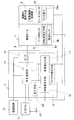
- FIG. 1 is a block diagram of a conceptual configuration of an electric brake device according to an embodiment of the present invention. It is explanatory drawing of the example of the brake force estimation. It is a graph which shows the example of the relationship between the motor angle and brake force in the electric brake device. It is a graph which shows the example of the relationship between the motor torque and brake force in the electric brake device. It is a flowchart which shows an example of control operation of the electric brake device. It is a flowchart which shows the other example of control operation of the electric brake device. It is a flowchart which shows the further another example of control action of the electric brake device. It is a side view which shows the electric brake actuator in the same electric brake device. It is side surface sectional drawing of the same electric brake actuator.
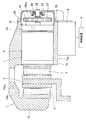
- This electric brake device includes an electric brake actuator 1, a control device 2 for controlling the electric brake actuator 1, a brake rotor 3 shown as an example in FIG. 8, and a pair of friction materials arranged with the brake rotor 3 interposed therebetween. 4 and 4.
- the friction material 4 is made of a friction pad.
- the brake rotor 3 is composed of a brake disk and rotates integrally with a wheel (not shown).
- the brake rotor 3 may be a brake drum.
- the electric brake actuator 1 includes a friction material operating means 5 that brings the friction material 4 into contact with the brake rotor 3, and an electric motor 6 that drives the friction material operating means 5.
- the electric motor 6 includes an AC motor such as a three-phase synchronous motor or an induction motor, or a DC motor.
- the friction material operating means 5 includes a linear motion mechanism or the like that converts a rotational input input from the electric motor 6 via a speed reduction mechanism (not shown) into a reciprocating linear motion of one friction material 4.
- a linear motion mechanism or the like that converts a rotational input input from the electric motor 6 via a speed reduction mechanism (not shown) into a reciprocating linear motion of one friction material 4.
- One friction material 4 is attached to the tip of the friction material operating means 5, and the other friction material 4 is attached to the other facing portion 7 b of the caliper body 7.
- the caliper body 7 is installed so as to be movable in the axial direction of the brake rotor 3 with respect to a mount (not shown) fixed to a knuckle (not shown) that supports the wheels.
- the electric motor 6 is provided with a rotation angle estimation means 8a such as a rotation angle sensor for estimating a motor rotation angle, and a current sensor 8b as one of the motor sensors 8.
- a rotation angle estimation means 8a such as a rotation angle sensor for estimating a motor rotation angle
- a current sensor 8b as one of the motor sensors 8.
- the control device 2 is a device for controlling the braking force by the electric motor 6 so as to obtain a given target braking force, and includes a microcomputer having a processor and a ROM (ReadROMOnly Memory) having a program executed by the processor. ), And other electronic circuits such as a RAM (Random Access Memory) and a co-processor. According to the amount of operation of the brake operation means 12 such as a brake pedal, the upper ECU 11 (or another means for instructing the brake force) determines the target brake force as a LUT (Look Up) implemented by software or hardware.
- a LUT Look Up
- the control device 2 generates a drive command composed of a torque command or a rotational speed command in accordance with the target brake force, and converts the drive command output from the control calculator 13 into a motor current for electric drive.
- a motor driver 14 for applying to the motor 6 is provided.
- the control calculator 13 performs feedback control using an estimated value of a brake force estimating means 16 described later.
- control arithmetic unit 13 receives the distributed input of the target brake force, the estimated value, the motor rotation angle, and the like using the above-described embodiment model, and receives the torque command or the drive command. And a software function on a hardware circuit or processor (not shown) that can perform feedback control and vector control.
- the motor driver 14 has, for example, a semiconductor bridge including an FET and an IGBT, and controls the motor current by PWM control.
- the control arithmetic unit 13 and the motor driver 14 are connected to a power supply device 15 such as a battery.
- the brake force estimation means 16 is composed of a direct estimation means 17 and an indirect estimation means 18.
- the direct estimation means 17 estimates the brake force from the output of the sensor element 19 a of the brake force sensor 19.
- the direct estimation unit 17 specifically converts the output of the brake force sensor 19 into an estimated brake force based on a predetermined correlation from the output of the sensor element 19a using the above-described implementation model. It is composed of hardware functions that can be output or software functions on a processor (not shown).
- the sensor element 19 a of the brake force sensor 19 includes a member such as the caliper body 7 that supports the friction material 4, the friction material operation means 5, and the friction material 4 or the friction material operation means 5. It is provided in the load member which is either.
- the sensor element 19a is a part of the load member or the like, that is, a part of the mechanical component of the electric brake device that is displaced or deformed by a brake force, or a part of which the load changes. It is provided and detects its displacement, deformation, load and the like.
- the sensor element 19a is, for example, as also shown in the same diagram the various exemplary arrangement in FIG. 8, the sensor element 19a 1 or the caliper body 7, detects a distortion of the friction material 4 is provided on the friction material 4 It may be a sensor element 19 a 2 that is provided and detects the distortion of the caliper body 7, or may be a sensor element 19 a 3 that detects displacement due to deformation of a member that supports the friction material operating means 5.
- the indirect estimation means 18 estimates a braking force outside the detection range of the braking force sensor 19 based on information other than the output of the sensor element 19 a of the braking force sensor 19, for example, the output of the motor sensor 8.
- the indirect estimation means 18 specifically estimates the braking force (estimated braking force) by receiving the output of the motor sensor 8 using the above-described realization model having a correlation map described later. And a hardware function or a software function on a processor (not shown).
- the motor sensor 8 includes, for example, motor angle estimation means 8a such as a motor angle sensor, or a current sensor 8b.
- the indirect estimation means 18 uses, for example, a predetermined relationship between the motor rotation angle and the braking force, and determines the motor rotation angle detected by the rotation angle estimation means 8a. Based on this, the braking force is estimated. Instead of the motor rotation angle, the rotation angle of the input shaft that inputs rotation to the electric motor 6 may be used. In addition, the indirect estimation means 18 uses a predetermined relationship between the motor current of the electric motor 6 and the braking force, and estimates the braking force based on the detected value of the motor current by the current sensor 8b. There may be.
- the range in which the braking force estimation means 16 estimates the braking force by the direct estimation means 17 is a predetermined low braking force range (for example, 0.3 G or less on a dry road surface), and a range exceeding this range. Then, the indirect estimation means 18 is configured to estimate the braking force.
- the indirect estimation means 18 may be based on a correlation obtained in advance by a test or the like, or may obtain a correlation from actual output transitions of the brake force sensor 19 and the motor sensor 8. For example, as shown in FIG. 3, a correlation map based on the correlation between the motor angle and the braking force may be prepared in advance, and the upper limit value F bmax of the setting range which is the range of the predetermined low braking force in FIG. The subsequent correlation may be estimated from the gradient in the vicinity of. Moreover, you may use such a method together.
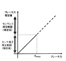
- FIG. 2 shows an example of brake force estimation.
- the sensorless estimation range in the figure shows the estimation range by the indirect estimation means 18.
- the sensor element detection range in the figure shows the detection range by the direct estimation means 17.
- the brake force estimation means 16 of FIG. 1 includes the direct estimation means 17 that is detected by the output of the brake force sensor 19 and the indirect estimation means 18 that does not use the brake force sensor 19. Use to estimate the total braking force area.
- the dynamic range of the sensor element 19a of the brake force sensor 19 may be smaller than when the entire range including the sensorless estimation range is detected by the output of the brake force sensor 19.
- a servo control system such as an electric brake device often uses a DSP (Digital Signal Processor) such as a microcomputer or FPGA (Field-Programmable Gate Array) for calculation, in which case the resolution of the A / D converter is used. Is equal to the detection resolution, the resolution of the brake force sensor 19 can be made higher in the example of FIG.
- DSP Digital Signal Processor
- FPGA Field-Programmable Gate Array
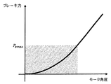
- FIG. 3 and 4 show examples of the correlation between each motor characteristic and the braking force.
- FIG. 3 shows an example based on the correlation between the motor rotation angle and the braking force.
- This correlation that is, the rigidity of the electric brake device can be measured in advance before mounting.
- the subsequent rigidity may be estimated from the gradient of the braking force with respect to the motor angle before reaching the set range upper limit value F bmax , which is the upper limit value of the determined low braking force range.
- the brake force sensor 19 see FIG. 1
- the indirect estimation means 18 uses the LUT based on the correlation in FIG. The estimation is made using an arithmetic expression, and the motor is controlled to reach a desired motor rotation angle.
- the non-linearity generally shows stronger non-linearity in the region where the braking force is lower, and the stiffness in this region varies greatly depending on the wear state of the friction material 4 and the temperature. To do. Therefore, a low brake force region that is difficult to estimate is estimated with high accuracy using the brake force sensor 19, and a relatively easy to estimate high brake force region is compensated by estimation from the motor angle or the like by the indirect estimation means 18. Can be configured.
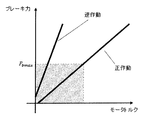
- FIG. 4 shows an example based on the correlation between the motor torque and the braking force.
- This correlation that is, the torque conversion coefficient of the electric brake device can be measured in advance before mounting. Alternatively, it may be estimated from the gradient of the braking force with respect to the motor torque before reaching the set range upper limit value F bmax .
- F bmax up to a set range upper limit value F bmax in the figure is detected by the brake force sensor 19 (see FIG. 1), and thereafter, estimation is performed using the LUT and mathematical expressions based on the correlation in FIG. Control to maintain.
- FIG. 5 shows an example of interpolating the estimated brake force value using the motor rotation angle when the estimated brake force value exceeds the set range upper limit value F bmax .
- the setting range upper limit value F bmax is preferably set to a value slightly smaller than the sensing limit.
- step R1 In the operation of drawing in order to compare the estimated braking force F b Range upper limit value F bmax (step R1), if it is substantially the same (at step R1 yes), the setting range upper limit value F bmax (step R5), and the motor control calculation is performed (step R4).
- Target value in the control calculation is F r, to the control amount and the estimated braking force F b.
- Step R1 when setting the estimated braking force F b range upper limit value F bmax is not substantially the same (no in step R1), it is determined whether the estimated braking force F b is the set range upper limit value F bmax or more (step R2 ), When the set range upper limit value F bmax is not exceeded (step R2: no), the control calculation (step R4) is performed. If the estimated braking force F b is the set range upper limit value F bmax or more (step R2: yes), the estimated braking force F b, and the setting range upper limit value F bmax + f ( ⁇ - ⁇ SW) ( step R3), Thereafter, the control calculation (step R4) is performed.
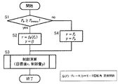
- FIG. 6 shows an example of switching to motor rotation angle control when the estimated braking force exceeds the estimated range.
- step S1 determines whether the estimated braking force F b is the set range upper limit value F bmax above, if it is set range upper limit value F bmax or more, the target value r f ⁇ (F r), the control
- the amount y is set to ⁇ (where Fr is the target brake force) (step S2), and control calculation is performed (step S3).
- the target value in this control calculation is r, and the control amount is y.
- step S1 Upon determination in step S1, when the estimated braking force F b is not set range upper limit value F bmax or more, the target value r F r, the controlled variable y and the estimated braking force F b (step S4), and the control calculation (step S3) is performed.
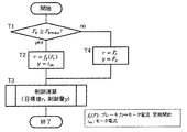
- FIG. 7 shows an example of switching to motor current control when the estimated braking force exceeds the estimated range.
- step T1 determines whether the estimated braking force F b is the set range upper limit value F bmax above, if it is set range upper limit value F bmax or more, the target value r and f c (F r), a control amount y i m (i m: motor current, F r: target braking force) and (step T2), performs control calculation (step T3).
- the target value in this control calculation is r, and the control amount is y.
- step T3 When the determination in step T1, if the estimated braking force F b is not set range upper limit value F bmax or more, the target value r F r, the controlled variable y and the estimated braking force F b (step T4), the control operation (step T3) is performed.
- the configuration of the brake force sensor having sufficient resolution in the normal range becomes easy, and the control accuracy can be improved and the cost can be reduced.
- the following calibration means 20 may be provided as shown in FIG.
- the calibration means 20 automatically activates the electric motor 6 when the vehicle speed of the vehicle equipped with the electric brake device is equal to or lower than a predetermined value (for example, a speed that can be regarded as a substantial stop or a speed at which a person walks).
- a predetermined value for example, a speed that can be regarded as a substantial stop or a speed at which a person walks.
- the indirect estimation means 18 is calibrated.
- the relationship between the motor rotation angle, motor current, etc., and braking force may change due to friction material wear, wear and deformation of each part, and other changes over time. Therefore, by providing the calibration means 20 and calibrating the indirect estimation means 18, it is possible to always maintain the estimation accuracy of the braking force of the indirect estimation means 18. Since the calibration means 20 operates this electric brake device and calibrates using the braking force detected by the direct estimation means 17, the calibration means 20 can calibrate with high precision, and the direct estimation means 17 and the indirect estimation means 18. The deviation of the estimated braking force can also be avoided.
- the operation of the electric brake device for calibration is performed when the vehicle speed of the vehicle is equal to or lower than a predetermined value, for example, in a state where the vehicle is stopped, the calibration can be performed safely without causing any trouble in running. This is preferable because it can be performed.
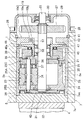
- the friction material operating means 5 has a linear motion mechanism 5a and a planetary mechanism type reduction machine 5b.
- the linear motion mechanism 5 a includes a rotating shaft 22, a plurality of planetary rollers 23 that are in rolling contact with the outer peripheral cylindrical surface of the rotating shaft 22, an outer ring member 24 disposed so as to surround these planetary rollers 23, and the planetary rollers 23.
- a brake force sensor 19 including a magnetic load sensor disposed rearward in the axial direction (rotating shaft 22) of the outer ring member 24.
- the rotary shaft 22 is rotationally driven by the rotation of the electric motor 6 shown in FIG. 8 being input via the gear 27 of FIG.
- the rotating shaft 22 is inserted into the receiving hole 7aa with one end protruding from the opening on the rear side in the axial direction of the receiving hole 7aa formed through the opposing portion 7a in the axial direction, and this protruding portion from the receiving hole 7aa
- the gear 27 is spline-fitted to prevent rotation.
- the gear 27 is covered with a lid 29 fixed with a bolt 28 so as to close the opening on the rear side in the axial direction of the accommodation hole 7aa.
- the lid 29 incorporates a bearing 30 that rotatably supports the rotary shaft 22.
- the planetary roller 23 is in rolling contact with the outer peripheral cylindrical surface of the rotating shaft 22, and when the rotating shaft 22 rotates, the planetary roller 23 also rotates due to friction between the planetary roller 23 and the rotating shaft 22. Yes.
- a plurality of planetary rollers 23 are provided at regular intervals in the circumferential direction of the rotating shaft 22.
- the outer ring member 24 is accommodated in an accommodation hole 7aa provided in the facing portion 7a of the caliper body 7, and is supported so as to be slidable in the axial direction on the inner periphery of the accommodation hole 7aa.
- an engagement recess 32 is formed that engages with an engagement protrusion 31 formed on the back surface of the friction material 4. The engagement protrusion 31 and the engagement recess 32 are engaged with each other. Thus, the outer ring member 24 is prevented from rotating with respect to the caliper body 7.
- a spiral ridge 33 is provided on the inner periphery of the outer ring member 24, and a circumferential groove 34 that engages with the spiral ridge 33 is provided on the outer periphery of the planetary roller 23, so that the planetary roller 23 rotates.
- the spiral ridge 33 of the outer ring member 24 is guided by the circumferential groove 34 so that the outer ring member 24 moves in the axial direction.
- the circumferential groove 34 having a lead angle of 0 degree is provided on the outer periphery of the planetary roller 23, but a spiral groove having a lead angle different from that of the spiral protrusion 33 may be provided instead of the circumferential groove 34.
- the carrier 25 includes a carrier pin 25A that rotatably supports the planetary roller 23, an annular carrier plate 25B that maintains a constant circumferential interval (around the rotation axis 22) of the front end in the axial direction of each carrier pin 25A,
- the carrier pin 25A includes an annular carrier body 25C that maintains a constant circumferential interval (around the rotation shaft 22) at the rear end in the axial direction of the carrier pin 25A.
- the carrier plate 25B and the carrier body 25C face each other in the axial direction with the planetary roller 23 interposed therebetween, and are connected in the circumferential direction via a connecting rod 35 disposed between the adjacent planetary rollers 23.
- the carrier body 25 ⁇ / b> C is supported on the rotary shaft 22 via the sliding bearing 36 and is rotatable relative to the rotary shaft 22.
- a thrust bearing 37 is installed between the planetary roller 23 and the carrier body 25C to block transmission of the rotation of the planetary roller 23 to the carrier body 25C.
- Each carrier pin 25A is urged radially inward by a reduced-diameter ring spring 38 that is mounted so as to circumscribe a plurality of carrier pins 25A arranged at intervals in the circumferential direction of the rotating shaft 22. . Due to the biasing force of the reduced diameter ring spring 38, the outer periphery of the planetary roller 23 is pressed against the outer periphery of the rotating shaft 22, and slippage between the rotating shaft 22 and the planetary roller 23 is prevented. In order to apply the urging force of the reduced diameter ring spring 38 over the entire axial length of the planetary roller 23, reduced diameter ring springs 38 are provided at both ends of the carrier pin 25A.
- the brake force sensor 19 is a magnetic load sensor, and is fitted in the accommodation hole 7aa in the direction of the rotation shaft 22 behind the flange portion 46 of the load input member 47 so that the support member 43 faces. Between the carrier 25 and the brake force sensor 19, a spacer 39 that revolves integrally with the carrier 25, and a thrust bearing 40 that transmits an axial load between the spacer 39 and the sensor mechanism portion 19c of the brake force sensor 19 are provided. Is incorporated.
- the thrust bearing 40 is provided so as to contact the inner diameter side portion of the flange portion 46 of the load input member 47, and an axial load is applied from the spacer 39 to the inner diameter side portion of the flange portion 46 via the thrust bearing 40. It is designed to be entered.
- the rotary shaft 22 is rotatably supported by a bearing 58 incorporated in the cylindrical portion 57 of the load input member 47.
- the sensor mechanism 19c of the brake force sensor 19 is restricted from moving rearward in the axial direction by locking the outer peripheral edge of the support member 43 with a retaining ring 41 attached to the inner periphery of the accommodation hole 7aa.
- the brake force sensor 19 restricts movement of the carrier 25 in the axial direction rearward by a configuration in which the carrier body 25C is supported in the axial direction via the spacer 39 and the thrust bearing 40.
- the carrier 25 is also restricted from moving forward in the axial direction by a retaining ring 42 attached to the front end of the rotating shaft 22 in the axial direction. Therefore, the movement of the carrier 25 in both the axial front and the axial rear is restricted, and the planetary roller 23 held by the carrier 25 is also restricted in the axial movement.
- a sensor target 19b such as a permanent magnet is provided in one of the parts that move in the axial direction as described above, and a sensor element 19a including a magnetic sensor is provided in the other part.
- the relative movement amount in the axial direction is detected as a load value.
- a load sensor which comprises the brake force sensor 19
- a capacitance sensor a reluctance detection sensor, an optical sensor, etc. other than a magnetic type can also be used.
Landscapes
- Engineering & Computer Science (AREA)
- Mechanical Engineering (AREA)
- General Engineering & Computer Science (AREA)
- Transportation (AREA)
- Braking Systems And Boosters (AREA)
- Regulating Braking Force (AREA)
- Braking Arrangements (AREA)
Abstract
広いダイナミックレンジを持ちながら、常用域において十分な分解能を有するブレーキ力推定手段の構成が容易となり、制御精度向上や低コスト化を可能とできる電動ブレーキ装置を提供する。電動モータ(6)、摩擦材操作手段(5)、摩擦材(4)、ブレーキロータ(3)、および制御装置(2)を有する。制御装置(2)に設けられるブレーキ力推定手段(16)として、荷重または変位対応量を検出するブレーキ力センサ(19)の出力をブレーキ力に変換する直接推定手段(17)と、前記ブレーキ力センサ(19)の出力以外の情報を元にブレーキ力を推測する間接推定手段(18)とを設ける。直接推定手段(17)によりブレーキ力を推定する範囲は、定められた低ブレーキ力の範囲とし、この範囲を超過する範囲では、間接推定手段(18)によりブレーキ力の推定を行う。
Description
本出願は、2015年6月1日出願の特願2015-111136の優先権を主張するものであり、その全体を参照により本願の一部をなすものとして引用する。
この発明は、ブレーキ力の推定機能を備え、車両等に搭載される電動ブレーキ装置に関する。
電動ブレーキ装置は、ブレーキロータ、摩擦材、減速機構や直動機構からなり該摩擦材を前記ブレーキロータと接触させる摩擦材操作手段、および摩擦材操作手段を駆動する電動モータによって構成される。また、ドライバのペダル操作量(踏力、ストローク等)や車両の状態から適切なブレーキ力を発生させるように摩擦材とブレーキロータとの間の摩擦力が制御される。その際、ブレーキ力を精度よく制御するために、前記ブレーキ力を推定するブレーキ力センサが用いられる。ブレーキ力センサに係る提案として、特許文献1~6の磁気センサや荷重センサを用いる提案がなされている。
一般に、車両用ブレーキは、例えば通常0.2G以下程度の減速度で使用されることが多く、その際にドライバは車両の挙動に合わせてペダル等を操作し細かくブレーキの制御を行っているため、ブレーキ力センサは、ドライバに違和感を抱かせないために十分な検出精度が求められる。一方、大きな車両減速度が必要となる急制動時においては、一般にドライバがフィーリングに合わせてペダルを細かく制御するようなケースは稀であり、ブレーキ力センサの検出精度は比較的粗くとも問題ないと考えられる。
また、前記ブレーキ力を推定する手段として、前記各特許文献のような、直動機構の軸方向荷重を検出するブレーキ荷重センサが比較的安価に構成できるため有用であり、その場合、電動ブレーキ装置は摩擦材とブレーキロータの押圧力を制御する。その際、摩擦材とブレーキロータの摩擦係数はその温度によって変化し、例えば高速走行時から激しい制動を繰り返す場合などにおいて、摩擦係数が1/3程度になる場合があることが知られている(フェード現象)。よって、前記ブレーキ荷重センサにはフェード現象を想定した押圧力を検出する広いダイナミックレンジが求められるが、その結果として、フェード現象が発生しない常用域において十分な分解能を得ることが困難となる場合がある。
前記の通り、ブレーキ力センサを比較的頻度の低い状況を想定した広いダイナミックレンジに設定すると、常用域において十分な分解能を得るために高精度な荷重センサを構成する必要が生じ、高コストとなる恐れがある。
この発明は、上記課題を解消するものであり、広いダイナミックレンジを持ちながら、常用域において十分な分解能を有するブレーキ力推定手段の構成が容易となり、制御精度向上や低コスト化を可能とできる電動ブレーキ装置を提供することを目的とする。
以下、この発明について、理解を容易にするために、便宜上実施形態の符号を参照して説明する。
この発明の電動ブレーキ装置は、ブレーキロータ3と、摩擦材4と、この摩擦材4を前記ブレーキロータ3と接触させる摩擦材操作手段5と、この摩擦材操作手段5を駆動する電動モータ6と、この電動モータ6のモータ回転角を推定する回転角推定手段8aと、ブレーキ力を推定するブレーキ力推定手段16と、目標ブレーキ力となるように前記電動モータ6によりブレーキ力を制御する制御装置2とを備える電動ブレーキ装置であって、
前記ブレーキ力推定手段16は、
前記摩擦材4、前記摩擦材操作手段5、および前記摩擦材4もしくは摩擦材操作手段5を支持する部材7のいずれかに作用する荷重または変位対応量を検出するブレーキ力センサ19の出力を推定ブレーキ力に変換する直接推定手段17と、前記ブレーキ力センサ19の出力以外の情報を元にブレーキ力を推測する間接推定手段18とを有し、
前記直接推定手段17により前記ブレーキ力を推定する範囲が、定められた低ブレーキ力の範囲であり、この範囲を超過する範囲では、前記間接推定手段18によりブレーキ力の推定を行う。
なお、この明細書で、前記「荷重または変位対応量」とは、荷重および変位の他、歪などの荷重または変位に換算できる物理量を含む意味である。
前記ブレーキ力推定手段16は、
前記摩擦材4、前記摩擦材操作手段5、および前記摩擦材4もしくは摩擦材操作手段5を支持する部材7のいずれかに作用する荷重または変位対応量を検出するブレーキ力センサ19の出力を推定ブレーキ力に変換する直接推定手段17と、前記ブレーキ力センサ19の出力以外の情報を元にブレーキ力を推測する間接推定手段18とを有し、
前記直接推定手段17により前記ブレーキ力を推定する範囲が、定められた低ブレーキ力の範囲であり、この範囲を超過する範囲では、前記間接推定手段18によりブレーキ力の推定を行う。
なお、この明細書で、前記「荷重または変位対応量」とは、荷重および変位の他、歪などの荷重または変位に換算できる物理量を含む意味である。
この構成によると、ブレーキ力推定手段16が、ブレーキ力によって発生する荷重または変位対応量を検出するブレーキ力センサ19を用いた直接推定手段17と、間接推定手段18とを有し、直接推定手段17は、定められた低ブレーキ力の範囲の検出を行えれば良いため、前記センサ素子19aとして高精度な検出が行えるものが安価に得られる。直接推定手段17の推定範囲を超過する範囲では、前記間接推定手段18によりブレーキ力の推定を行えば良い。前記直接推定手段17の推定範囲を超過するような大きなブレーキ力を与える場合は、ドライバがフィーリングに合わせてペダルを細かく制御するようなケースは稀であり、ブレーキ力センサ19の検出精度は比較的粗くとも問題ない。そのため、荷重または変位対応量を検出するブレーキ力センサ19は不要であり、モータ回転角やモータ電流等からでも推定が行える。そのため、例えばフェード状態を想定した押圧力を検出できるような、広いダイナミックレンジを持ちながら、常用域において十分な分解能を有するブレーキ力推定手段16の構成が容易となり、制御精度向上や低コスト化を可能とできる。
この発明において、前記間接推定手段18が、前記モータ回転角と前記ブレーキ力との定められた関係を用い、前記回転角推定手段8aにより検出されるモータ回転角に基づいてブレーキ力を推定する構成であっても良い。摩擦材4を動作させる電動モータ6のモータ回転角とブレーキ力とは、ある程度定まった関係があるため、その関係を試験やシミュレーション等で求めおくことで、モータ回転角に基づいてブレーキ力を推定することができる。モータ回転角を検出する回転角センサ等の回転角推定手段8aは、モータ制御のために一般的に電動モータ6に付随して設けられるため、その回転角推定手段8aを用いれば良い。そのため、前記間接推定手段18が簡単な構成で得られる。
この発明において、前記間接推定手段18が、前記電動モータ6のモータ電流と前記ブレーキ力との定められた関係を用い、電流センサ8bによるモータ電流を検出値に基づいてブレーキ力を推定する構成であっても良い。摩擦材4を動作させる電動モータ6のモータ電流とブレーキ力とは、ある程度定まった関係があるため、その関係を試験やシミュレーション等で求めおくことで、モータ電流に基づいてブレーキ力を推定することができる。電流センサ8bは簡単な構成で安価なものが多くあり、それを用いれば良い。そのため、この構成の場合も、前記間接推定手段18が簡単な構成で得られる。
この発明において、前記直接推定手段17の用いるブレーキ力センサ19が、前記摩擦材4と前記ブレーキロータ3との接触力による、前記摩擦材4、摩擦材操作手段5、および前記摩擦材4もしくは摩擦材操作手段5を支持する部材7のいずれかの変形量を検出するものであっても良い。摩擦材4とブレーキロータ3との接触力により、電動ブレーキ装置の各部に弾性変形が生じる。前記ブレーキ力センサ19は、そのような弾性変形を検出する。変形を検出するブレーキ力センサ19のセンサ素子19aは、検出できる範囲が限られたものであれば、高精度な検出をできるものが種々存在する。そのようなセサン素子19aを用いることで、ブレーキ力を高精度に検出できる直接推定手段17が安価に製造できる。
この発明において、前記直接推定手段17により推定された前記推定ブレーキ力と、前記電動モータ6のモータ回転角およびモータ電流との少なくとも何れか一つ以上との関係に基づいて、前記間接推定手段18の校正を行う校正手段20を有するようにしても良い。経年変化等により、モータ回転角やモータ電流等とブレーキ力との関係が変化することがある。そのため、前記校正手段20を設けて前記間接推定手段18の校正を行うことで、前記間接推定手段18のブレーキ力の推定精度を常に維持することができる。前記校正手段20は、この電動ブレーキ装置を作動させて前記直接推定手段17により検出したブレーキ力を用いて校正を行うため、精度良く校正することができ、また直接推定手段17と間接推定手段18の推定ブレーキ力の乖離も回避できる。
前記校正手段20を設けた場合に、この電動ブレーキ装置を搭載した車両の車速が所定値以下のときに、前記車両の操縦者の指示によらず電動モータ6を作動させ、前記校正手段20に基づき前記間接推定手段18の校正を行うようにしても良い。校正のための電動ブレーキ装置の作動を、車両の車速が所定値以下のときに行うようにした場合、走行の障害を生じさせずに安全に校正が行える。
請求の範囲および/または明細書および/または図面に開示された少なくとも2つの構成のどのような組合せも、この発明に含まれる。特に、請求の範囲の各請求項の2つ以上のどのような組合せも、この発明に含まれる。
この発明は、添付の図面を参考にした以下の好適な実施形態の説明から、より明瞭に理解されるであろう。しかしながら、実施形態および図面は単なる図示および説明のためのものであり、この発明の範囲を定めるために利用されるべきものではない。この発明の範囲は添付の請求の範囲によって定まる。添付図面において、複数の図面における同一の符号は、同一または相当する部分を示す。
この発明の一実施形態を図面と共に説明する。この電動ブレーキ装置は、電動ブレーキアクチュエータ1と、この電動ブレーキアクチュエータ1を制御する制御装置2と、図8に一例を示すブレーキロータ3と、このブレーキロータ3を挟んで配置された一対の摩擦材4,4とを備える。摩擦材4は摩擦バッドからなる。ブレーキロータ3は、この例ではブレーキディスクからなり、車輪(図示せず)と一体に回転する。ブレーキロータ3は、ブレーキドラムであっても良い。電動ブレーキアクチュエータ1は、摩擦材4をブレーキロータ3と接触させる摩擦材操作手段5と、この摩擦材操作手段5を駆動する電動モータ6とを備える。電動モータ6は、3相の同期モータまたは誘導モータ等の交流モータ、または直流モータ等からなる。
摩擦材操作手段5は、電動モータ6から減速機構(不図示)を介して入力される回転入力を、片方の摩擦材4の往復直線運動に変換する直動機構等で構成され、キャリパボディ7におけるブレーキロータ3を挟む一組の対向部7a、7bのうちの一方の対向部7aに設置されている。摩擦材操作手段5の先端に一方の摩擦材4が取付けられ、他方の摩擦材4はキャリパボディ7の他方の対向部7bに取付けられている。キャリパボディ7は、車輪を支持するナックル(図示せず)に固定されたマウント(図示せず)に対して、ブレーキロータ3の軸方向に移動可能に設置されている。同図の電動ブレーキアクチュエータ1の具体的な構造例は、後に図9と共に説明する。
図1において、電動モータ6には、モータ用センサ8の一つとして、モータ回転角を推定する回転角センサ等の回転角推定手段8aと、電流センサ8bとが設けられている。
制御装置2は、与えられた目標ブレーキ力となるように、前記電動モータ6によりブレーキ力を制御する装置であり、プロセッサを有するマイクロコンピュータや前記プロセッサで実行されるプログラムを有するROM(Read Only Memory)、およびRAM(Random Access Memory)やコプロセッサ(Co-Processor)等の他の電子回路等からなる。前記目標ブレーキ力を、上位ECU11が(または他のブレーキ力を指令する手段が)、ブレーキベダル等のブレーキ操作手段12の操作量に応じて、ソフトウエアやハードウエアで実現されたLUT(Look Up Table)、またはソフトウエアのライブラリ(Library)に収められた所定の変換関数(以下、「具現化モデル」という。)を用いて、各々のブレーキ力の指令値を生成して、各輪の電動ブレーキ装置における制御装置2毎に分配する。制御装置2は、前記目標ブレーキ力に応じてトルク指令または回転数指令からなる駆動指令を生成する制御演算器13と、この制御演算器13から出力された駆動指令をモータ電流に変換して電動モータ6に印加するモータドライバ14とが設けられている。制御演算器13は、後述のブレーキ力推定手段16の推定値を用いてフィードバック制御する。制御演算器13がベクトル制御する構成である場合は、前記回転角推定手段8aの検出するモータ回転角を用いてモータの効率化を高める制御を行う。制御演算器13は、具体的には、上記の具現化モデルを用いて、分配された前記目標ブレーキ力、前記推定値および前記モータ回転角等の入力を受けて、前記トルク指令または前記駆動指令を生成し、かつフィードバック制御さらにはベクトル制御を行いうるハードウエア回路またはプロセッサ(不図示)上のソフトウエア関数で構成されている。モータドライバ14は、例えば、FETやIGBTを含む半導体ブリッジ等を有し、PWM制御によってモータ電流を制御する。制御演算器13およびモータドライバ14は、バッテリ等の電源装置15に接続されている。
上記基本構成の制御装置2において、前記ブレーキ力推定手段16が、直接推定手段17と間接推定手段18とで構成されている。
前記直接推定手段17は、ブレーキ力センサ19のセンサ素子19aの出力からブレーキ力を推定する。例えば、前記直接推定手段17は、具体的には、上記の具現化モデルを用いて、センサ素子19aの出力から、ブレーキ力センサ19の出力を所定の相関に基づいて推定ブレーキ力に変換して出力しうるハードウエア回路またはプロセッサ(不図示)上のソフトウエア関数で構成されている。ブレーキ力センサ19のセンサ素子19aは、図9に示すように、前記摩擦材4、前記摩擦材操作手段5、および前記摩擦材4もしくは摩擦材操作手段5を支持する前記キャリパボディ7等の部材のいずれかである荷重部材に設けられている。前記センサ素子19aは、前記荷重部材等の部分すなわち、この電動ブレーキ装置の機械的な構成部分のいずれかにおける、ブレーキ力によって変位や、歪等の変形が生じる部分、または荷重が変化する部分に設けられ、その変位、変形、荷重等を検出する。前記センサ素子19aは、例えば、図8に各種の配置例を同じ図上で併記するように、摩擦材4に設けられて摩擦材4の歪を検出するセンサ素子19a1、またはキャリパボディ7に設けられてキャリパボディ7の歪を検出するセンサ素子19a2であっても良く、摩擦材操作手段5を支持する部材の変形による変位を検出するセンサ素子19a3であっても良い。
図1において、間接推定手段18は、ブレーキ力センサ19のセンサ素子19aの出力以外の情報、例えばモータ用センサ8の出力を元に、ブレーキ力センサ19の検出範囲外のブレーキ力を推定する。例えば、間接推定手段18は、具体的には、後述の相関マップ等を有した上記の具現化モデルを用いて、モータ用センサ8の出力を受けて、ブレーキ力(推定ブレーキ力)を推定して出力しうるハードウエア回路またはプロセッサ(不図示)上のソフトウエア関数で構成されている。モータ用センサ8は、例えばモータ角度センサ等のモータ角度推定手段8a、または電流センサ8b等からなる。
すなわち、間接推定手段18は、電動ブレーキ装置の剛性を測定した結果、例えば、モータ回転角と前記ブレーキ力との定められた関係を用い、前記回転角推定手段8aにより検出されるモータ回転角に基づいてブレーキ力を推定する構成とされる。モータ回転角の代わりに、電動モータ6に回転を入力する入力軸の回転角を用いるようにしても良い。前記間接推定手段18は、この他に、電動モータ6の前記モータ電流と前記ブレーキ力との定められた関係を用い、電流センサ8bによるモータ電流の検出値に基づいてブレーキ力を推定する構成であっても良い。
前記ブレーキ力推定手段16は、前記直接推定手段17により前記ブレーキ力を推定する範囲は、定められた低ブレーキ力の範囲(例えば乾燥路面では0.3G以下)とされ、この範囲を超過する範囲では、前記間接推定手段18によりブレーキ力の推定を行う構成とされる。
間接推定手段18は、予め試験等によって求めた相関に基づいても良く、実際のブレーキ力センサ19とモータセンサ8の出力推移より相関を求めても良い。例えば図3に示すような、予めモータ角度とブレーキ力の相関に基づく相関マップ等を用意しても良く、図3中の前記定められた低ブレーキ力の範囲である設定範囲の上限値Fbmaxの近傍における勾配から以降の相関を推定しても良い。また、こうした手法を併用しても良い。
上記構成の作用を説明する。図2は、ブレーキ力推定例を示す。同図のセンサレス推定範囲は、間接推定手段18による推定範囲を示す。同図のセンサ素子検出範囲は、直接推定手段17による検出範囲を示す。前述のように、図1のブレーキ力推定手段16は、ブレーキ力センサ19の出力による検出する直接推定手段17と、ブレーキ力センサ19を用いない間接推定手段18とを備えており、その双方を用いて全ブレーキ力領域の推定を行う。
前記センサレス推定範囲を含めた範囲の全てをブレーキ力センサ19の出力で検出する場合と比較して、図2の例によるブレーキ力センサ19のセンサ素子19aのダイナミックレンジは小さくて良い。一般に、電動ブレーキ装置のようなサーボ制御系にはマイコンやFPGA(Field-Programmable Gate Array)のようなDSP(Digital Signal Processor)を演算に用いる場合が多く、その場合にA/D変換器の分解能が検出分解能に等しくなるため、図2の例のほうがブレーキ力センサ19の分解能を高くすることができる。また、上記の場合においてセンサの分解能が同等以上であれば十分な場合や、図2のように狭い範囲の検出で良い場合には、例えばセンサ構成部品の寸法公差やセンサ取付誤差を緩和・許容することができ、コスト低減が可能となる。
図3,図4は、各モータ特性とブレーキ力との相関の例を示す。図3は、モータ回転角とブレーキ力との相関に基づく例を示す。この相関、すなわち電動ブレーキ装置の剛性は、実装前に予め測定することができる。もしくは、前記定められた低いブレーキ力の範囲の上限値である設定範囲上限値Fbmaxに到達する前のモータ角度に対するブレーキ力の勾配から以降の剛性を推測し、演算しても良い。ここでは、図中の設定範囲上限値Fbmaxまではブレーキ力センサ19(図1参照)により検出し、それ以降は間接推定手段18(図1参照)により、図3の相関に基づいたLUTや演算式を用いて推定し、所望のモータ回転角に到達するようモータを制御する。
この時、主に摩擦材4(図8参照)の非線形剛性により、一般にブレーキ力が低い領域ほど強い非線形を示し、この領域の剛性は摩擦材4の摩耗状態や温度等に依存して大きく変化する。よって、推定の難しい低ブレーキ力領域はブレーキ力センサ19を用いて高精度に推定し、比較的推定し易い高ブレーキ力領域は間接推定手段18によるモータ角度等からの推定によって補うという、合理的な構成をとることができる。
図4は、モータトルクとブレーキ力との相関に基づく例を示す。この相関すなわち電動ブレーキ装置のトルク変換係数は、実装前に予め測定することができる。もしくは、設定範囲上限値Fbmaxに到達する前のモータトルクに対するブレーキ力の勾配から推測しても良い。ここでは、図中の設定範囲上限値Fbmaxまではブレーキ力センサ19(図1参照)により検出し、それ以降は図4の相関に基づいたLUTや数式を用いて推定し、所望のモータ電流を維持するよう制御する。その際、ブレーキを加圧する場合すなわち正作動時と、ブレーキを減圧する場合すなわち逆作動時において、同図に示すようにヒステリシスを有する特性を考慮する必要がある。例えば、所定のブレーキ力まで加圧する場合、正作動特性において縦軸のブレーキ力に相当する横軸のモータトルクを出力すれば、電動ブレーキ装置のブレーキ力は概ね前記所定のブレーキ力に到達する。
この時、主に電動ブレーキアクチュエータ1(図8参照)における軸受、減速機、直動機構(ねじ、ボールランプ、etc)の摩擦抵抗や、電動モータ6(図8参照)のコギングトルク等の割合が、モータトルクに対して比較的大きい領域、すなわちブレーキ力およびトルクが低い領域における相関を正確に把握することは難しい。よって、推定の難しい低ブレーキ領域はブレーキ力センサ19を用いて高精度に推定し、比較的推定し易い高ブレーキ領域はモータ回転角やモータ電流等からの間接的な推定により補うという、合理的な構成をとることができる。
図5~図7は、この実施形態の実装フローの各例を示す。図5は、ブレーキ力推定値が、設定範囲上限値Fbmaxの超過した場合に、モータ回転角を用いてブレーキ力推定値を補間する例を示す。このとき、設定範囲上限値Fbmaxは、センシングの限界よりわずかに小さい値に設定しておくことが好ましい。
同図の動作を順に説明すると、推定ブレーキ力Fbと設定範囲上限値Fbmaxとを比較し(ステップR1)、略同じである場合は(ステップR1でyes)、設定範囲上限値Fbmaxにおけるモータ回転角θSWをモータ回転角θとし(ステップR5)、モータの制御演算を行う(ステップR4)。この制御演算における目標値(目標ブレーキ力)はFrであり、その制御量を推定ブレーキ力Fbとする。
ステップR1で、推定ブレーキ力Fbと設定範囲上限値Fbmaxが略同じでない場合(ステップR1でno)、推定ブレーキ力Fbが設定範囲上限値Fbmax以上であるかを判定し(ステップR2)、設定範囲上限値Fbmax以上でない場合は(ステップR2:no)、前記制御演算(ステップR4)を行う。推定ブレーキ力Fbが設定範囲上限値Fbmax以上である場合は(ステップR2:yes)、推定ブレーキ力Fbを、設定範囲上限値Fbmax+f(θ-θSW)とし(ステップR3)、その後、前記の制御演算(ステップR4)を行う。
図6は、ブレーキ力推定値が推定範囲を超過した場合、モータ回転角制御に切り替える例を示す。ステップS1において、推定ブレーキ力Fbが設定範囲上限値Fbmax以上であるか否かを判定し、設定範囲上限値Fbmax以上である場合は、目標値rをfθ(Fr)、制御量yをθとし(ただしFrは目標ブレーキ力)(ステップS2)、制御演算を行う(ステップS3)。この制御演算における目標値はrであり、制御量はyである。ステップS1の判断時に、推定ブレーキ力Fbが設定範囲上限値Fbmax以上でない場合は、目標値rをFr、制御量yを推定ブレーキ力Fbとし(ステップS4)、前記制御演算(ステップS3)を行う。
図7は、ブレーキ力推定値が推定範囲を超過した場合、モータ電流制御に切り替える例を示す。ステップT1において、推定ブレーキ力Fbが設定範囲上限値Fbmax以上であるか否かを判定し、設定範囲上限値Fbmax以上である場合は、目標値rをfc(Fr)とし、制御量yをim(im:モータ電流、Fr:目標ブレーキ力)(ステップT2)とし、制御演算を行う(ステップT3)。この制御演算における目標値はrであり、制御量はyである。ステップT1の判断時に、推定ブレーキ力Fbが設定範囲上限値Fbmax以上でない場合は、目標値rをFr、制御量yを推定ブレーキ力Fbとし(ステップT4)、前記制御演算(ステップT3)を行う。
この実施形態の電動ブレーキ装置によると、上記のように、常用域において十分な分解能を有するブレーキ力センサの構成が容易となり、制御精度向上や低コスト化を可能とする。
上記構成の電動ブレーキ装置において、図1に示すように、次の校正手段20を設けても良い。この校正手段20は、この電動ブレーキ装置を搭載した車両の車速が所定値(例えば、略停止とみなせる速度、または人が歩行する程度の速度)以下のときに前記電動モータ6を自動で作動させ、この作動を行っている間における、前記直接推定手段17により推定された前記推定ブレーキ力と、前記電動モータ6のモータ回転角および前記電動モータ6のモータ電流との少なくとも何れか一つ以上との関係に基づいて、前記間接推定手段18の校正を行う。
摩擦材の摩耗、各部品の摩耗や変形、その他の経年変化等により、モータ回転角やモータ電流等とブレーキ力との関係が変化することがある。そのため、前記校正手段20を設けて前記間接推定手段18の校正を行うことで、前記間接推定手段18のブレーキ力の推定精度を常に維持することができる。前記校正手段20は、この電動ブレーキ装置を作動させて前記直接推定手段17により検出したブレーキ力を用いて校正を行うため、精度良く校正することができ、また直接推定手段17と間接推定手段18の推定ブレーキ力の乖離も回避できる。このとき、校正のための電動ブレーキ装置の作動は、例えば車両が停止している状態などの、車両の車速が所定値以下のときに行うと、走行の障害を生じさせずに安全に校正が行えるため好適である。
次に、図8の電動ブレーキ装置の電動ブレーキアクチュエータ1の具体例を図9と共に説明する。この例では、その摩擦材操作手段5が、直動機構5aおよび遊星機構形式の減速機械5bを有する。直動機構5aは、回転軸22と、回転軸22の外周の円筒面に転がり接触する複数の遊星ローラ23と、これらの遊星ローラ23を囲むように配置された外輪部材24と、遊星ローラ23を自転可能かつ公転可能に保持するキャリヤ25と、外輪部材24の軸(回転軸22)方向後方に配置された磁気式荷重センサからなるブレーキ力センサ19とを有する。
回転軸22は、図8に示す電動モータ6の回転が図9の歯車27を介して入力されることにより回転駆動される。回転軸22は、対向部7aを軸方向に貫通して形成された収容孔7aaの軸方向後側の開口から一端が突出した状態で収容孔7aaに挿入され、収容孔7aaからのこの突出部分に歯車27がスプライン嵌合して回り止めされている。歯車27は、収容孔7aaの軸方向後側の開口を塞ぐようにボルト28で固定した蓋29で覆われている。蓋29には回転軸22を回転可能に支持する軸受30が組み込まれている。
遊星ローラ23は、回転軸22の外周の円筒面に転がり接触しており、回転軸22が回転したときに遊星ローラ23と回転軸22の間の摩擦によって遊星ローラ23も回転するようになっている。遊星ローラ23は、回転軸22の周方向に一定の間隔をおいて複数設けられている。
外輪部材24は、キャリパボディ7の対向部7aに設けられた収容孔7aa内に収容され、その収容孔7aaの内周で軸方向にスライド可能に支持されている。外輪部材24の軸方向前端には、摩擦材4の背面に形成された係合凸部31に係合する係合凹部32が形成され、この係合凸部31と係合凹部32の係合によって、外輪部材24がキャリパボディ7に対して回り止めされている。
外輪部材24の内周には螺旋凸条33が設けられ、遊星ローラ23の外周には、螺旋凸条33に係合する円周溝34が設けられており、遊星ローラ23が回転したときに、外輪部材24の螺旋凸条33が円周溝34に案内されて、外輪部材24が軸方向に移動するようになっている。ここでは遊星ローラ23の外周にリード角が0度の円周溝34を設けているが、円周溝34のかわりに螺旋凸条33と異なるリード角をもつ螺旋溝を設けてもよい。
キャリヤ25は、遊星ローラ23を回転可能に支持するキャリヤピン25Aと、その各キャリヤピン25Aの軸方向前端の周方向間隔(回転軸22周り)を一定に保持する環状のキャリヤプレート25Bと、各キャリヤピン25Aの軸方向後端の周方向間隔(回転軸22周り)を一定に保持する環状のキャリヤ本体25Cとからなる。キャリヤプレート25Bとキャリヤ本体25Cは遊星ローラ23を間に挟んで軸方向に対向しており、周方向に、隣り合う遊星ローラ23の間に配置された連結棒35を介して連結されている。
キャリヤ本体25Cは、滑り軸受36を介して回転軸22に支持され、回転軸22に対して相対回転可能となっている。遊星ローラ23とキャリヤ本体25Cの間には、遊星ローラ23の自転がキャリヤ本体25Cに伝達するのを遮断するスラスト軸受37が組み込まれている。
各キャリヤピン25Aは、回転軸22の周方向に間隔をおいて配置された複数のキャリヤピン25Aに外接するように装着された縮径リングばね38で、径方向内方に付勢されている。この縮径リングばね38の付勢力によって、遊星ローラ23の外周は回転軸22の外周に押さえ付けられ、回転軸22と遊星ローラ23の間の滑りが防止されている。縮径リングばね38の付勢力を遊星ローラ23の軸方向全長にわたって作用させるため、キャリヤピン25Aの両端に縮径リングばね38が設けられている。
ブレーキ力センサ19は、磁気式荷重センサであって、回転軸22方向において、荷重入力部材47のフランジ部46の後方に、支持部材43が対向する向きで収容孔7aa内に嵌め込まれている。キャリヤ25とブレーキ力センサ19の間には、キャリヤ25と一体に公転する間座39と、間座39とブレーキ力センサ19のセンサ機構部19cの間で軸方向荷重を伝達するスラスト軸受40とが組み込まれている。スラスト軸受40は、荷重入力部材47のフランジ部46の内径側部分に接触するように設けられており、このスラスト軸受40を介して間座39からフランジ部46の内径側部分に軸方向荷重が入力されるようになっている。荷重入力部材47の円筒部57内に組み込まれた軸受58で、回転軸22が回転可能に支持されている。
ブレーキ力センサ19のセンサ機構部19cは、支持部材43の外周縁を収容孔7aaの内周に装着した止め輪41で係止することによって、軸方向後方への移動が規制されている。そして、このブレーキ力センサ19は、間座39とスラスト軸受40とを介してキャリヤ本体25Cを軸方向に支持する構成により、キャリヤ25の軸方向後方への移動を規制している。また、キャリヤ25は、回転軸22の軸方向前端に装着された止め輪42で軸方向前方への移動も規制されている。したがって、キャリヤ25は、軸方向前方と軸方向後方の移動がいずれも規制され、キャリヤ25に保持された遊星ローラ23も軸方向移動が規制された状態となっている。
同図のブレーキ力センサ19は、上記のようにして互いに軸方向に動く部品の一方の部品に永久磁石などのセンサターゲット19bが設けられ、他方の部品に磁気センサからなるセンサ素子19aが設けられ、その軸方向の相対移動量を荷重値として検出する。
なお、ブレーキ力センサ19を構成する荷重センサとしては、磁気式の他に、静電容量センサ、リラクタンス検出センサ、光学センサ等を利用したものを用いることも可能である。
以上、図面を参照しながら実施形態に基づいてこの発明を実施するための好適な形態を説明したが、今回開示された実施の形態はすべての点で例示であって制限的なものではない。この発明の範囲は上記した説明ではなくて請求の範囲によって示される。当業者であれば、本件明細書を見て、自明な範囲内で種々の変更および修正を容易に想定するであろう。したがって、そのような変更および修正は、請求の範囲から定まる発明の範囲内またはこれと均等の範囲内のものと解釈される。
1…電動ブレーキアクチュエータ
2…制御装置
3…ブレーキロータ
4…摩擦材
5…摩擦材操作手段
6…電動モータ
8a…回転角推定手段
8b…電流センサ
11…上位ECU
16…ブレーキ力推定手段
17…直接推定手段
18…間接推定手段
19…ブレーキ力センサ
19a…センサ素子
20…校正手段
2…制御装置
3…ブレーキロータ
4…摩擦材
5…摩擦材操作手段
6…電動モータ
8a…回転角推定手段
8b…電流センサ
11…上位ECU
16…ブレーキ力推定手段
17…直接推定手段
18…間接推定手段
19…ブレーキ力センサ
19a…センサ素子
20…校正手段
Claims (6)
- ブレーキロータと、摩擦材と、この摩擦材を前記ブレーキロータと接触させる摩擦材操作手段と、この摩擦材操作手段を駆動する電動モータと、この電動モータのモータ回転角を推定する回転角推定手段と、ブレーキ力を推定するブレーキ力推定手段と、目標ブレーキ力となるように前記電動モータによりブレーキ力を制御する制御装置とを備える電動ブレーキ装置であって、
前記ブレーキ力推定手段は、
前記摩擦材、前記摩擦材操作手段、および前記摩擦材もしくは摩擦材操作手段を支持する部材のいずれかに作用する荷重または変位対応量を検出するブレーキ力センサの出力を推定ブレーキ力に変換する直接推定手段と、前記ブレーキ力センサの出力以外の情報を元にブレーキ力を推測する間接推定手段とを有し、
前記直接推定手段により前記ブレーキ力を推定する範囲が、定められた低ブレーキ力の範囲であり、この範囲を超過する範囲では、前記間接推定手段によりブレーキ力の推定を行う、
電動ブレーキ装置。 - 請求項1に記載の電動ブレーキ装置において、前記間接推定手段が、前記モータ回転角と前記ブレーキ力との定められた関係を用い、前記回転角推定手段により検出されるモータ回転角に基づいてブレーキ力を推定する電動ブレーキ装置。
- 請求項1に記載の電動ブレーキ装置において、前記間接推定手段が、前記電動モータのモータ電流と前記ブレーキ力との定められた関係を用い、電流センサによるモータ電流の検出値に基づいてブレーキ力を推定する電動ブレーキ装置。
- 請求項1ないし請求項3のいずれか1項に記載の電動ブレーキ装置において、前記ブレーキ力センサが、前記摩擦材と前記ブレーキロータとの接触力による、前記摩擦材、摩擦材操作手段、および前記摩擦材もしくは摩擦材操作手段を支持する部材のいずれかの変形量を検出する電動ブレーキ装置。
- 請求項1ないし請求項4のいずれか1項に記載の電動ブレーキ装置において、前記直接推定手段により推定された前記推定ブレーキ力と、前記電動モータのモータ回転角およびモータ電流との少なくとも何れか一つ以上との関係に基づいて、前記間接推定手段の校正を行う校正手段を有する電動ブレーキ装置。
- 請求項5に記載の電動ブレーキ装置において、この電動ブレーキ装置を搭載した車両の車速が所定値以下のときに、前記車両の操縦者の指示によらず電動モータを作動させ、前記校正手段に基づき前記間接推定手段の校正を行うことを特徴とする、電動ブレーキ装置。
Priority Applications (3)
| Application Number | Priority Date | Filing Date | Title |
|---|---|---|---|
| CN201680031348.4A CN107614337B (zh) | 2015-06-01 | 2016-05-27 | 电动制动装置 |
| EP16803265.4A EP3305609B1 (en) | 2015-06-01 | 2016-05-27 | Electrically powered brake device |
| US15/825,936 US10479342B2 (en) | 2015-06-01 | 2017-11-29 | Electrically powered brake device |
Applications Claiming Priority (2)
| Application Number | Priority Date | Filing Date | Title |
|---|---|---|---|
| JP2015-111136 | 2015-06-01 | ||
| JP2015111136A JP6133360B2 (ja) | 2015-06-01 | 2015-06-01 | 電動ブレーキ装置 |
Related Child Applications (1)
| Application Number | Title | Priority Date | Filing Date |
|---|---|---|---|
| US15/825,936 Continuation US10479342B2 (en) | 2015-06-01 | 2017-11-29 | Electrically powered brake device |
Publications (1)
| Publication Number | Publication Date |
|---|---|
| WO2016194830A1 true WO2016194830A1 (ja) | 2016-12-08 |
Family
ID=57441222
Family Applications (1)
| Application Number | Title | Priority Date | Filing Date |
|---|---|---|---|
| PCT/JP2016/065766 Ceased WO2016194830A1 (ja) | 2015-06-01 | 2016-05-27 | 電動ブレーキ装置 |
Country Status (5)
| Country | Link |
|---|---|
| US (1) | US10479342B2 (ja) |
| EP (1) | EP3305609B1 (ja) |
| JP (1) | JP6133360B2 (ja) |
| CN (1) | CN107614337B (ja) |
| WO (1) | WO2016194830A1 (ja) |
Families Citing this family (25)
| Publication number | Priority date | Publication date | Assignee | Title |
|---|---|---|---|---|
| JP6605248B2 (ja) * | 2015-07-27 | 2019-11-13 | Ntn株式会社 | 摩擦ブレーキシステム |
| JP6575421B2 (ja) * | 2016-04-08 | 2019-09-18 | 株式会社アドヴィックス | 車両の制動制御装置 |
| EP3260339A1 (en) * | 2016-06-20 | 2017-12-27 | Haldex Brake Products Aktiebolag | Disc brake actuator for a vehicle |
| US10173661B2 (en) * | 2016-11-23 | 2019-01-08 | GM Global Technology Operations LLC | Brake fade management system for a brake-by-wire system |
| IT201700073192A1 (it) * | 2017-06-29 | 2018-12-29 | Itt Italia Srl | Dispositivo di calibrazione automatica di una pastiglia per freni |
| IT201700086468A1 (it) * | 2017-07-27 | 2019-01-27 | Freni Brembo Spa | Metodo di stima di una forza frenante esercitabile tra pastiglia e disco freno da un sistema elettrico di frenatura di stazionamento di un veicolo e sistema elettrico di frenatura di stazionamento di un veicolo implementante tale metodo |
| JP6921197B2 (ja) * | 2017-07-27 | 2021-08-18 | 日立Astemo株式会社 | 車両用ブレーキシステム |
| CN110550011B (zh) * | 2018-05-31 | 2021-11-12 | 比亚迪股份有限公司 | 制动力估算方法、装置、存储介质及车辆 |
| JP7451503B2 (ja) * | 2018-09-19 | 2024-03-18 | ブレンボ・ソチエタ・ペル・アツィオーニ | モータサイクル用の自動制御されたブレーキ・バイ・ワイヤ式ブレーキシステム |
| IT201800009105A1 (it) * | 2018-10-02 | 2020-04-02 | Freni Brembo Spa | Metodo di controllo di un impianto frenante di un veicolo e relativo sistema |
| JP7220783B2 (ja) * | 2019-06-12 | 2023-02-10 | 本田技研工業株式会社 | 自転車の電動アシスト装置及び自転車 |
| CN114026004A (zh) * | 2019-06-26 | 2022-02-08 | 日立安斯泰莫株式会社 | 电动制动装置、制动控制装置以及控制参数校准方法 |
| CN110525411A (zh) * | 2019-09-30 | 2019-12-03 | 浙江力邦合信智能制动系统股份有限公司 | 电子驻车制动器和电子驻车制动方法 |
| DE102020208853A1 (de) | 2020-07-15 | 2022-01-20 | Chassis Brakes International B.V. | Verfahren zum Ermitteln einer Spannkraft einer Bremseinrichtung eines Kraftfahrzeugs, Verfahren zum Betreiben eines Kraftfahrzeugs, Vorrichtung |
| FR3116497B1 (fr) * | 2020-11-23 | 2024-02-16 | Foundation Brakes France | Procédé de commande du couple de serrage d’un frein électromécanique amélioré |
| IT202100024236A1 (it) * | 2021-09-21 | 2023-03-21 | Brembo Spa | Metodo e sistema di controllo di un impianto frenante |
| IT202100028913A1 (it) * | 2021-11-15 | 2023-05-15 | Brembo Spa | Dispositivo di rilevazione della forza di serraggio di una pinza freno e sistema di controllo di un impianto frenante |
| KR102660858B1 (ko) | 2022-05-12 | 2024-04-24 | 현대모비스 주식회사 | 전동식 브레이크 및 그 제어방법 |
| DE102022204709A1 (de) * | 2022-05-13 | 2023-11-16 | Robert Bosch Gesellschaft mit beschränkter Haftung | Bremsvorrichtung, elektromechanisches Bremssystem und Verfahren zum Betreiben eines elektromechanischen Bremssystems |
| US12134376B2 (en) * | 2022-09-21 | 2024-11-05 | Baidu Usa Llc | Electrical power conservation during braking for autonomous or assisted driving vehicles |
| US12365325B2 (en) * | 2023-03-13 | 2025-07-22 | GM Global Technology Operations LLC | Brake actuator control systems and methods |
| CN116639103B (zh) * | 2023-07-27 | 2023-11-14 | 北京理工大学深圳汽车研究院(电动车辆国家工程实验室深圳研究院) | 一种双冗余制动力检测的电子机械制动装置和车辆 |
| JP2025075722A (ja) * | 2023-10-31 | 2025-05-15 | 株式会社アドヴィックス | 電動制動装置 |
| EP4711216A1 (en) * | 2024-09-11 | 2026-03-18 | KB Intellectual Property GmbH & Co. KG | Force determination unit for determining a force feedback, electro-mechanical actuator assembly and method for determining a force feedback |
| FR3167982A1 (fr) * | 2024-10-24 | 2026-05-01 | Hitachi Astemo France | Etrier de frein comportant un capteur et frein comportant un tel étrier |
Citations (2)
| Publication number | Priority date | Publication date | Assignee | Title |
|---|---|---|---|---|
| JP2014101960A (ja) * | 2012-11-21 | 2014-06-05 | Advics Co Ltd | 車両の電動制動装置 |
| JP2014177207A (ja) * | 2013-03-15 | 2014-09-25 | Advics Co Ltd | 車両の電動制動装置 |
Family Cites Families (13)
| Publication number | Priority date | Publication date | Assignee | Title |
|---|---|---|---|---|
| JP4834397B2 (ja) * | 2005-12-15 | 2011-12-14 | 日立オートモティブシステムズ株式会社 | 車両のブレーキ制御装置 |
| JP5022915B2 (ja) * | 2006-02-08 | 2012-09-12 | 日立オートモティブシステムズ株式会社 | 電動ブレーキ装置 |
| JP5778513B2 (ja) | 2011-07-28 | 2015-09-16 | Ntn株式会社 | 直動アクチュエータ用の磁気式荷重センサおよび直動アクチュエータ |
| JP5735882B2 (ja) | 2011-08-02 | 2015-06-17 | Ntn株式会社 | 磁気式荷重センサ |
| JP5833405B2 (ja) | 2011-10-11 | 2015-12-16 | Ntn株式会社 | 直動アクチュエータ用の磁気式荷重センサおよび直動アクチュエータ |
| JP5865184B2 (ja) | 2012-06-13 | 2016-02-17 | Ntn株式会社 | 磁気式荷重センサおよび電動ブレーキ装置 |
| JP5877134B2 (ja) | 2012-07-11 | 2016-03-02 | Ntn株式会社 | 磁気式荷重センサおよび電動ブレーキ装置 |
| WO2014080992A1 (ja) | 2012-11-21 | 2014-05-30 | 株式会社アドヴィックス | 車両の電動制動装置 |
| JP5947229B2 (ja) | 2013-01-10 | 2016-07-06 | Ntn株式会社 | 磁気式荷重センサおよび電動ブレーキ装置 |
| DE112014001455B4 (de) * | 2013-03-15 | 2018-09-06 | Advics Co., Ltd. | Elektrisches Bremssystem für ein Fahrzeug |
| JP5915863B2 (ja) * | 2013-03-15 | 2016-05-11 | 株式会社アドヴィックス | 車両の電動制動装置 |
| WO2014142335A1 (ja) | 2013-03-15 | 2014-09-18 | 株式会社アドヴィックス | 車両の電動制動装置 |
| JP5849978B2 (ja) * | 2013-03-15 | 2016-02-03 | 株式会社アドヴィックス | 車両の電動制動装置 |
-
2015
- 2015-06-01 JP JP2015111136A patent/JP6133360B2/ja not_active Expired - Fee Related
-
2016
- 2016-05-27 WO PCT/JP2016/065766 patent/WO2016194830A1/ja not_active Ceased
- 2016-05-27 CN CN201680031348.4A patent/CN107614337B/zh not_active Expired - Fee Related
- 2016-05-27 EP EP16803265.4A patent/EP3305609B1/en active Active
-
2017
- 2017-11-29 US US15/825,936 patent/US10479342B2/en active Active
Patent Citations (2)
| Publication number | Priority date | Publication date | Assignee | Title |
|---|---|---|---|---|
| JP2014101960A (ja) * | 2012-11-21 | 2014-06-05 | Advics Co Ltd | 車両の電動制動装置 |
| JP2014177207A (ja) * | 2013-03-15 | 2014-09-25 | Advics Co Ltd | 車両の電動制動装置 |
Non-Patent Citations (1)
| Title |
|---|
| See also references of EP3305609A4 * |
Also Published As
| Publication number | Publication date |
|---|---|
| EP3305609A4 (en) | 2019-01-09 |
| EP3305609A1 (en) | 2018-04-11 |
| CN107614337B (zh) | 2019-12-27 |
| EP3305609B1 (en) | 2020-02-19 |
| CN107614337A (zh) | 2018-01-19 |
| JP2016222134A (ja) | 2016-12-28 |
| US20180079403A1 (en) | 2018-03-22 |
| US10479342B2 (en) | 2019-11-19 |
| JP6133360B2 (ja) | 2017-05-24 |
Similar Documents
| Publication | Publication Date | Title |
|---|---|---|
| JP6133360B2 (ja) | 電動ブレーキ装置 | |
| US10100891B2 (en) | Electric brake device | |
| CN106796455B (zh) | 提供对力觉感的改进控制的力觉接口 | |
| US9797462B2 (en) | Electric linear motion actuator and electric brake system | |
| CN109789858B (zh) | 电动制动装置 | |
| US10384659B2 (en) | Electric brake device | |
| US10427661B2 (en) | Electric brake device | |
| WO2014087813A1 (ja) | 電動式直動アクチュエータ | |
| US20180154872A1 (en) | Electric brake device | |
| JP2020093721A (ja) | 電動ブレーキ装置 | |
| WO2016181898A1 (ja) | 電動モータ装置および電動式直動アクチュエータ | |
| JP2003202042A (ja) | 電動ディスクブレーキおよびその制御プログラム | |
| JP7017940B2 (ja) | 電動式アクチュエータおよび電動ブレーキ装置 | |
| JP2005106153A (ja) | ブレーキ装置 | |
| JP7796485B2 (ja) | 電動ブレーキ装置 | |
| CN116615365B (zh) | 用于确定机动车的制动设备的夹紧力的方法和装置 | |
| JP6906398B2 (ja) | 電動ブレーキ装置 | |
| JP2019050649A (ja) | 電動式アクチュエータおよび電動モータ装置 | |
| JP6818861B1 (ja) | 電動ブレーキの制御装置 | |
| JP2008014323A (ja) | 電動ブレーキ装置 | |
| JP6605647B2 (ja) | 電動ブレーキ装置 |
Legal Events
| Date | Code | Title | Description |
|---|---|---|---|
| 121 | Ep: the epo has been informed by wipo that ep was designated in this application |
Ref document number: 16803265 Country of ref document: EP Kind code of ref document: A1 |
|
| NENP | Non-entry into the national phase |
Ref country code: DE |
|
| WWE | Wipo information: entry into national phase |
Ref document number: 2016803265 Country of ref document: EP |