WO2016194836A1 - 直流ブラシレスモータ制御装置 - Google Patents
直流ブラシレスモータ制御装置 Download PDFInfo
- Publication number
- WO2016194836A1 WO2016194836A1 PCT/JP2016/065781 JP2016065781W WO2016194836A1 WO 2016194836 A1 WO2016194836 A1 WO 2016194836A1 JP 2016065781 W JP2016065781 W JP 2016065781W WO 2016194836 A1 WO2016194836 A1 WO 2016194836A1
- Authority
- WO
- WIPO (PCT)
- Prior art keywords
- rotor
- magnetic pole
- detection unit
- brushless motor
- pole position
- Prior art date
- Legal status (The legal status is an assumption and is not a legal conclusion. Google has not performed a legal analysis and makes no representation as to the accuracy of the status listed.)
- Ceased
Links
Images


Classifications
-
- H—ELECTRICITY
- H02—GENERATION; CONVERSION OR DISTRIBUTION OF ELECTRIC POWER
- H02P—CONTROL OR REGULATION OF ELECTRIC MOTORS, ELECTRIC GENERATORS OR DYNAMO-ELECTRIC CONVERTERS; CONTROLLING TRANSFORMERS, REACTORS OR CHOKE COILS
- H02P6/00—Arrangements for controlling synchronous motors or other dynamo-electric motors using electronic commutation dependent on the rotor position; Electronic commutators therefor
- H02P6/06—Arrangements for speed regulation of a single motor wherein the motor speed is measured and compared with a given physical value so as to adjust the motor speed
-
- A—HUMAN NECESSITIES
- A47—FURNITURE; DOMESTIC ARTICLES OR APPLIANCES; COFFEE MILLS; SPICE MILLS; SUCTION CLEANERS IN GENERAL
- A47L—DOMESTIC WASHING OR CLEANING; SUCTION CLEANERS IN GENERAL
- A47L9/00—Details or accessories of suction cleaners, e.g. mechanical means for controlling the suction or for effecting pulsating action; Storing devices specially adapted to suction cleaners or parts thereof; Carrying-vehicles specially adapted for suction cleaners
- A47L9/28—Installation of the electric equipment, e.g. adaptation or attachment to the suction cleaner; Controlling suction cleaners by electric means
- A47L9/2805—Parameters or conditions being sensed
- A47L9/2831—Motor parameters, e.g. motor load or speed
-
- A—HUMAN NECESSITIES
- A47—FURNITURE; DOMESTIC ARTICLES OR APPLIANCES; COFFEE MILLS; SPICE MILLS; SUCTION CLEANERS IN GENERAL
- A47L—DOMESTIC WASHING OR CLEANING; SUCTION CLEANERS IN GENERAL
- A47L5/00—Structural features of suction cleaners
- A47L5/12—Structural features of suction cleaners with power-driven air-pumps or air-compressors, e.g. driven by motor vehicle engine vacuum
- A47L5/22—Structural features of suction cleaners with power-driven air-pumps or air-compressors, e.g. driven by motor vehicle engine vacuum with rotary fans
-
- A—HUMAN NECESSITIES
- A47—FURNITURE; DOMESTIC ARTICLES OR APPLIANCES; COFFEE MILLS; SPICE MILLS; SUCTION CLEANERS IN GENERAL
- A47L—DOMESTIC WASHING OR CLEANING; SUCTION CLEANERS IN GENERAL
- A47L9/00—Details or accessories of suction cleaners, e.g. mechanical means for controlling the suction or for effecting pulsating action; Storing devices specially adapted to suction cleaners or parts thereof; Carrying-vehicles specially adapted for suction cleaners
- A47L9/28—Installation of the electric equipment, e.g. adaptation or attachment to the suction cleaner; Controlling suction cleaners by electric means
-
- A—HUMAN NECESSITIES
- A47—FURNITURE; DOMESTIC ARTICLES OR APPLIANCES; COFFEE MILLS; SPICE MILLS; SUCTION CLEANERS IN GENERAL
- A47L—DOMESTIC WASHING OR CLEANING; SUCTION CLEANERS IN GENERAL
- A47L9/00—Details or accessories of suction cleaners, e.g. mechanical means for controlling the suction or for effecting pulsating action; Storing devices specially adapted to suction cleaners or parts thereof; Carrying-vehicles specially adapted for suction cleaners
- A47L9/28—Installation of the electric equipment, e.g. adaptation or attachment to the suction cleaner; Controlling suction cleaners by electric means
- A47L9/2836—Installation of the electric equipment, e.g. adaptation or attachment to the suction cleaner; Controlling suction cleaners by electric means characterised by the parts which are controlled
- A47L9/2842—Suction motors or blowers
-
- H—ELECTRICITY
- H02—GENERATION; CONVERSION OR DISTRIBUTION OF ELECTRIC POWER
- H02P—CONTROL OR REGULATION OF ELECTRIC MOTORS, ELECTRIC GENERATORS OR DYNAMO-ELECTRIC CONVERTERS; CONTROLLING TRANSFORMERS, REACTORS OR CHOKE COILS
- H02P6/00—Arrangements for controlling synchronous motors or other dynamo-electric motors using electronic commutation dependent on the rotor position; Electronic commutators therefor
- H02P6/08—Arrangements for controlling the speed or torque of a single motor
- H02P6/085—Arrangements for controlling the speed or torque of a single motor in a bridge configuration
-
- H—ELECTRICITY
- H02—GENERATION; CONVERSION OR DISTRIBUTION OF ELECTRIC POWER
- H02P—CONTROL OR REGULATION OF ELECTRIC MOTORS, ELECTRIC GENERATORS OR DYNAMO-ELECTRIC CONVERTERS; CONTROLLING TRANSFORMERS, REACTORS OR CHOKE COILS
- H02P6/00—Arrangements for controlling synchronous motors or other dynamo-electric motors using electronic commutation dependent on the rotor position; Electronic commutators therefor
- H02P6/14—Electronic commutators
- H02P6/16—Circuit arrangements for detecting position
- H02P6/17—Circuit arrangements for detecting position and for generating speed information
-
- H—ELECTRICITY
- H02—GENERATION; CONVERSION OR DISTRIBUTION OF ELECTRIC POWER
- H02P—CONTROL OR REGULATION OF ELECTRIC MOTORS, ELECTRIC GENERATORS OR DYNAMO-ELECTRIC CONVERTERS; CONTROLLING TRANSFORMERS, REACTORS OR CHOKE COILS
- H02P6/00—Arrangements for controlling synchronous motors or other dynamo-electric motors using electronic commutation dependent on the rotor position; Electronic commutators therefor
- H02P6/28—Arrangements for controlling current
Definitions
- the present invention relates to a DC brushless motor control device.
- Patent Document 1 an electric blower that controls the power or the number of revolutions of the electric blower based on the current or the negative pressure of the electric blower is known (for example, Patent Document 1).
- the present invention has been made in view of the above circumstances, and an object thereof is to provide a user-friendly DC brushless motor control device.
- the direct current brushless motor control device is a direct current brushless motor control device for supplying a current to a winding of a stator of a three-phase direct current brushless motor that rotates a suction fan of a suction device.
- a three-phase bridge inverter unit including an arm, in each phase, in which an arm is connected in series and the connection point between the switching elements and one end of the winding are connected, and the magnetic pole position of the rotor of the three-phase DC brushless motor Of the switching elements provided in the arm on the basis of the magnetic pole position detected by the magnetic pole position detecting section that detects the current flowing through the first switching element on one side of the connection point and the second on the other side.
- a control unit that controls the number of rotations of the rotor by controlling the energization state of the switching element;
- Storage configured to store an operation detection unit that detects an operation on the suction device and information indicating the target number of rotations of the rotor divided into a plurality of stages of rotation numbers corresponding to the operation detected by the operation detection unit
- the control unit is configured to control the target rotation number corresponding to the operation detected by the operation detection unit, the rotation number of the rotor indicated by the period of movement of the magnetic pole position detected by the magnetic pole position detection unit.
- the number of revolutions of the rotor is controlled by feedback of the number of revolutions of the rotor or by feedback of the current value supplied to the winding.
- FIG. 1 is a view showing an example of the appearance of a suction device according to the present embodiment.
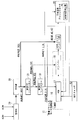
- FIG. 2 is a view showing an example of the functional configuration of the suction device according to the present embodiment.
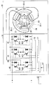
- FIG. 3 is a view showing an example of the configuration of a three-phase bridge inverter unit and a three-phase DC brushless motor provided in the suction device according to the present embodiment.
- FIG. 4 is a view showing an example of the structure of a three-phase DC brushless motor.
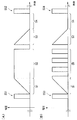
- FIG. 5 is a diagram showing an example of voltage waveforms of the three-phase bridge inverter unit.
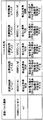
- FIG. 6 is a diagram showing an example of the relationship between the rotational speed of the rotor controlled by the MCU and the target rotational speed.
- FIG. 7 is a diagram showing an example of the period of movement of the magnetic pole position detected by the magnetic pole position detection unit.
- FIG. 8 is a diagram illustrating two operation modes of the MCU.
- FIG. 1 is a view showing an example of the appearance of a suction device 1 according to the present embodiment.
- the suction device 1 includes an operation switch 13.
- FIG. 2 is a view showing an example of the functional configuration of the suction device 1 according to the present embodiment.
- the suction device 1 includes an operation switch 13, a DC brushless motor control device 15, a three-phase DC brushless motor 20, a rectifier 29, a booster 30, a first DC-DC converter 31, and a second DC-DC converter 32. Equipped with The DC brushless motor control device 15 includes a control unit 16 and a three-phase bridge inverter unit 40.
- the DC brushless motor control device 15 supplies current to the windings 21, 22 and 23 of the stator of the three-phase DC brushless motor 20 that rotates the suction fan of the suction device 1.
- the control unit 16 includes an MCU (Micro Controller Unit) 17 and a driver 18.
- MCU Micro Controller Unit
- the MCU 17 includes an operation detection unit (not shown) that detects an operation on the operation switch 13. That is, the operation detection unit detects an operation on the suction device 1.
- the three-phase DC brushless motor 20 includes a magnetic pole position detection unit 25.
- the control unit 16 is a connection point among the switching elements included in the arms 41, 42, 43 based on the magnetic pole position detected by the magnetic pole position detection unit 25 that detects the magnetic pole position of the rotor 24 of the three-phase DC brushless motor 20.
- the rotational speed of the rotor 24 is controlled by controlling the energization state of the first switching element on one side and the energization state of the second switching element on the other side.
- FIG. 3 is a view showing an example of the configuration of the three-phase bridge inverter unit 40 and the three-phase DC brushless motor 20 provided in the suction device 1 according to the present embodiment.
- the three-phase bridge inverter unit 40 includes an arm 41, an arm 42, and an arm 43.
- the arm 41 includes a field effect transistor 411 and a field effect transistor 412.
- the arm 42 includes a field effect transistor 421 and a field effect transistor 422.
- the arm 43 includes a field effect transistor 431 and a field effect transistor 432. That is, in the three-phase bridge inverter unit 40, the arms 41, 42, 43 in which the switching elements are connected in series and in which the connection point between the switching elements and one end of the windings 21, 22, 23 are connected Prepare for
- the three-phase DC brushless motor 20 includes a winding 21, a winding 22, a winding 23, a rotor 24, a magnetic pole position detector 25-1, a magnetic pole position detector 25-2, and a magnetic pole position detector 25. And a permanent magnet 241.
- the aforementioned magnetic pole position detection unit 25 is a generic term for the magnetic pole position detection unit 25-1, the magnetic pole position detection unit 25-2, and the magnetic pole position detection unit 25-3.
- the magnetic pole position detection unit 25-1 will be collectively referred to as the magnetic pole position detection unit 25 unless the magnetic pole position detection unit 25-1, the magnetic pole position detection unit 25-2, and the magnetic pole position detection unit 25-3 need to be distinguished.
- FIG. 4 is a view showing an example of the structure of the three-phase DC brushless motor 20.
- FIG. 5 is a diagram showing an example of voltage waveforms for controlling the field effect transistor 411, the field effect transistor 421, and the field effect transistor 431 by the three-phase bridge inverter unit 40.
- the field effect transistor 411, the field effect transistor 421, and the field effect transistor 431 are each an example of a first switching element.
- the field effect transistor 412, the field effect transistor 422, and the field effect transistor 432 are each an example of a second switching element.
- the field effect transistor 411, the field effect transistor 421, and the field effect transistor 431 will be collectively referred to as a first switching element unless it is necessary to distinguish them.
- the field effect transistor 412, the field effect transistor 422, and the field effect transistor 432 are collectively referred to as a second switching element unless it is necessary to distinguish them.
- FIG. 5A is an example of a voltage waveform in which the three-phase bridge inverter unit 40 controls the first switching element when the number of rotations of the rotor 24 included in the three-phase DC brushless motor 20 is equal to or more than a predetermined number of rotations.
- the rotational speed of the rotor 24 is calculated by the MCU 17 based on the magnetic pole position detected by the magnetic pole position detection unit 25.
- the three-phase bridge inverter unit 40 sequentially operates the first switching element from the time when the magnetic pole position detected by the magnetic pole position detector 25 reaches the reference position. Control is performed according to a plurality of states including a first state S1, a second state S2, a third state S3, and a fourth state S4.
- both the first switching element and the second switching element are in the off state.
- the first switching element is maintained in the on state, and the second switching element is maintained in the off state.
- both the first switching element and the second switching element are in the off state.
- the fourth state S4 the first switching element is maintained in the off state, and the second switching element is maintained in the on state.
- control of the first switching element based on the voltage waveform shown in FIG. 5A is referred to as one pulse control.
- the DC brushless motor control device 15 can reduce switching loss by one-pulse control.
- FIG. 5B is an example of a voltage waveform in which the three-phase bridge inverter unit 40 controls the first switching element when the number of rotations of the rotor 24 included in the three-phase DC brushless motor 20 is less than a predetermined number of rotations.
- the predetermined rotation number is 20000 [r / m] (revolution per minutes) in this example.
- the three-phase bridge inverter unit 40 sequentially operates the first switching element from the time when the magnetic pole position detected by the magnetic pole position detection unit 25 reaches the reference position. Control is performed according to a plurality of states including a first state S1, a fifth state S5, a third state S3, and a fourth state S4.
- the first switching element is alternately switched between the on state and the off state.
- control of the first switching element based on the voltage waveform shown in FIG. 5B is referred to as PWM (Pulse Width Modulation) control.
- FIG. 6 is a diagram showing an example of the relationship between the rotational speed of the rotor 24 controlled by the MCU 17 by the three-phase bridge inverter unit 40 and the target rotational speed.
- the MCU 17 causes the three-phase bridge inverter unit 40 to control the first switching element with the voltage waveform shown in FIG. 5B while the calculated rotation speed of the rotor 24 is less than the predetermined rotation speed.
- the MCU 17 controls the first switching element by the three-phase bridge inverter unit 40 according to the voltage waveform shown in FIG.
- the DC brushless motor control device 15 can achieve both controllability and efficiency by performing PWM control with good controllability in the low speed region and one pulse control with high efficiency in the high speed region.
- the MCU 17 Based on the operation accepted by the operation switch 13, the MCU 17 reads information indicating the target rotation number of the level corresponding to the operation from the storage unit 12.
- the storage unit 12 stores information indicating the target number of revolutions of the rotor 24 divided into a plurality of stages of number of revolutions corresponding to the operation detected by the operation detection unit. More specifically, in the storage unit 12, information indicating the target number of revolutions of the rotor 24 corresponds to the number of revolutions of a plurality of stages corresponding to the stages of suction force of the suction device 1 indicated by the operation detected by the operation detection unit. It is divided and memorized.
- the target rotational speed levels are, for example, five levels of level 1 to level 5.
- Each of these target rotational speed levels is associated with the suction work rate of the suction device 1 according to each target rotational speed.
- the MCU 17 causes the three-phase bridge inverter unit 40 to control the first switching element so that the read target rotational speed matches the calculated rotational speed of the rotor 24.
- the DC brushless motor control device 15 can control the three-phase DC brushless motor 20 at a rotational speed of a level suitable for the use situation of the suction device 1.
- the suction device 1 is a vacuum cleaner
- the DC brushless motor control device 15 controls the three-phase DC brushless motor 20 at a rotational speed of a level suitable for the floor conditions such as flooring, tatami, carpet and the like. can do.
- the rotation of the rotor 24 When the rotation speed of the rotor 24 becomes equal to or more than the target rotation speed, the rotation of the rotor 24 may be stopped. Thus, when the rotational speed of the rotor 24 exceeds the target rotational speed due to some factor, the rotation of the rotor 24 can be automatically stopped. In the case of FIG. 6, for example, control may be performed so that the rotor 24 automatically stops when the target rotational speed of level 5 is exceeded.
- the MCU 17 When changing the rotation speed of the rotor 24 according to the level of the target rotation speed, the MCU 17 changes the duration of the second state in the one pulse control according to the target rotation speed of the rotor 24. As a result, the DC brushless motor control device 15 can control the rotor rotational speed in one-pulse control.
- the term "duration” as used herein refers to a time that changes in accordance with the number of rotations of the rotor 24, and does not mean an absolute time.
- the suction device 1 may include a battery as an operation power supply of the three-phase DC brushless motor 20.
- the battery may be, for example, a secondary battery such as a nickel-cadmium battery, a nickel-hydrogen battery, or a lithium ion battery.
- the MCU 17 may change the target rotational speed of the rotor 24 based on the remaining power of the battery. That is, the control unit 16 controls the number of rotations of the rotor 24 based on the remaining amount of the secondary battery that supplies power to the three-phase DC brushless motor 20.
- the MCU 17 controls the rotational speed of the rotor 24 by reducing the target rotational speed of the rotor 24 when the remaining power amount of the battery is less than a predetermined threshold value.
- the predetermined threshold may be a value indicating a specific remaining power amount, or may be a predetermined ratio. In this example, the predetermined threshold is a predetermined percentage. The predetermined ratio is, for example, 20% of the capacity of the battery.
- flow brushless motor control apparatus 15 can lengthen the usable time of the attraction
- the MCU 17 may perform other processing such as holding the target rotation speed at a predetermined value, when the remaining power amount of the battery is less than the predetermined threshold value.
- the DC brushless motor control device 15 can extend the usable time of the suction device 1 when the remaining power amount of the secondary battery is small.
- the MCU 17 may perform control to switch the target rotation number of the rotor 24 depending on whether the remaining power amount of the battery is equal to or more than a predetermined threshold value or less than the predetermined threshold value. Specifically, the MCU 17 controls the number of revolutions of the rotor 24 without changing the target number of revolutions of the rotor 24 when the remaining power of the battery is equal to or greater than a predetermined threshold value. Further, the MCU 17 controls the rotational speed of the rotor 24 by reducing the target rotational speed of the rotor 24 when the remaining power amount of the battery is less than the predetermined threshold value.
- DC brushless motor control device 15 maintains a predetermined suction force when the remaining power of the battery is equal to or greater than a predetermined threshold, and the remaining power of the battery is determined to a predetermined value. If it is less than the threshold value, the operation time can be increased. That is, the DC brushless motor control device 15 can switch between the power maintenance mode and the energy saving mode, for example, according to the remaining power amount of the battery.
- FIG. 7 is a diagram showing an example of a period of movement of the magnetic pole position detected by the magnetic pole position detection unit 25.
- the MCU 17 is based on the period of movement of the magnetic pole position detected by the magnetic pole position detection unit 25 as to whether a signal indicating the magnetic pole position supplied from the magnetic pole position detection unit 25 is acquired as a signal used for determination of the magnetic pole position.
- the time required for one cycle of the electrical angle changes according to the change in the rotational speed of the rotor 24. Specifically, the time required for one cycle of the electrical angle is shorter when the rotor 24 rotates at a high speed than when the rotor 24 rotates at a low speed.
- the change speed of the rotational speed of the rotor 24 is within the predetermined range, the change of the time required for one cycle of the electrical angle is also within the predetermined range. That is, as one example, within a minute time in which the rotor 24 rotating at a high speed of about 20000 [r / m] or more rotates several times, the change in time required for one electrical angle cycle is extremely small. Therefore, the MCU 17 can estimate the width of the time required for one electrical angle cycle after the minute time has elapsed from the calculated timing by calculating the time required for one electrical angle cycle. That is, the MCU 17 can estimate at what timing the signal indicating the magnetic pole position is generated.
- the MCU 17 determines that the signal indicating the magnetic pole position generated at the timing within the width of the time required for one estimated electrical angle cycle among the signals indicating the magnetic pole position is not noise. The MCU 17 determines to acquire a signal indicating the magnetic pole position determined not to be noise as a signal used for determining the magnetic pole position. Further, the MCU 17 determines that the signal indicating the magnetic pole position generated at the timing outside the width of the time required for one estimated electric angle cycle among the signals indicating the magnetic pole position is noise. The MCU 17 determines that a signal indicating the magnetic pole position determined to be noise is not acquired as a signal used for determining the magnetic pole position.
- the MCU 17 can also feedback-control the rotational speed of the rotor 24 based on the period of movement of the magnetic pole position detected by the magnetic pole position detection unit 25 and the target rotational speed of the rotor 24.
- the MCU 17 operates in one of the two operation modes shown in FIG.
- FIG. 8 is a diagram illustrating two operation modes of the MCU 17.
- the two operation modes are, for example, a current holding mode and a rotational speed holding mode.
- the MCU 17 controls the number of rotations of the rotor 24 by feedback of the current value supplied to each of the winding 21, the winding 22, and the winding 23.
- the current value supplied to the winding 21, the winding 22, and the winding 23 is detected by a current sensor (not shown).
- the MCU 17 supplies the winding 21, the winding 22, and the winding 23 based on the difference between the current value of the winding 21, the winding 22, and the winding 23 detected by the current sensor and the target current value. Calculate the current value to be Further, the MCU 17 supplies the current of the calculated current value to the winding 21, the winding 22, and the winding 23.
- the operation mode of the MCU 17 is the rotation speed holding mode
- the MCU 17 controls the rotation speed of the rotor 24 by feedback of the rotation speed of the rotor 24.
- the MCU 17 calculates the number of rotations of the rotor 24 based on the change period of the magnetic pole position detected by the magnetic pole position detection unit 25. Further, the MCU 17 calculates a voltage waveform to be supplied to the winding 21, the winding 22, and the winding 23 based on the difference between the calculated rotational speed of the rotor 24 and the target rotational speed. Further, the MCU 17 supplies the current of the calculated voltage waveform to the winding 21, the winding 22, and the winding 23. The MCU 17 controls the rotation speed when the rotation speed of the rotor 24 indicated by the period of movement of the magnetic pole position detected by the magnetic pole position detection unit 25 exceeds the target rotation speed corresponding to the operation detected by the operation detection unit. To do.
- the control unit 16 The rotational speed of the rotor 24 is controlled by the feedback of the rotational speed of 24 or by the feedback of the current value supplied to the windings 21, 22, 23.
- the DC brushless motor control device 15 can suppress the heat generation due to the rotation speed of the rotor 24 unintentionally rising from the target rotation speed which is the target upper limit value by feedback.
- the operation detected by the operation detection unit is an operation of selecting a stage of suction force of the suction device in this example. That is, the operation on the suction device is an operation to select the stage of suction force of the suction device.
- the information indicating the target number of revolutions of the rotor 24 corresponds to the stage of suction force of the suction device 1 indicated by the operation detected by the operation detection unit. It is divided into and stored.
- the MCU 17 reads out from the storage unit 12 information indicating the target rotational speed of the stage corresponding to the stage of the suction force corresponding to the operation detected by the operation detection unit.
- the MCU 17 matches the rotational speed of the rotor 24 with the read target rotational speed.
- the DC brushless motor control device 15 can provide the user with the operation of the suction device 1 based on the suction force.
- the suction device 1 is an example of a suction device.
Landscapes
- Engineering & Computer Science (AREA)
- Power Engineering (AREA)
- Mechanical Engineering (AREA)
- Control Of Motors That Do Not Use Commutators (AREA)
- Electric Vacuum Cleaner (AREA)
Abstract
吸引装置の吸引ファンを回転させる三相直流ブラシレスモータの固定子の巻線に対して電流を供給する直流ブラシレスモータ制御装置であって、ロータの回転数を制御する制御部と、吸引装置に対する操作を検出する操作検出部と、ロータの目標回転数を示す情報が、操作検出部が検出する操作に対応する複数の段階の回転数に区切られて記憶されている記憶部と、を備え、制御部は、磁極位置検出部が検出する磁極位置の移動の周期が示すロータの回転数が、操作検出部が検出する操作に対応する目標回転数を超える場合には、ロータの回転数のフィードバックにより、又は巻線に供給される電流値のフィードバックによりロータの回転数を制御する。
Description
本発明は、直流ブラシレスモータ制御装置に関する。
従来、電動送風機の電流もしくは負圧に基づいて、電動送風機の電力または回転数の制御を行う電動送風機が知られている(例えば、特許文献1)。
しかしながら、電動送風機の電流もしくは負圧の閾値に関して、バリエーションをもたせておらず、最適な制御が十分できているとは言えない、という問題があった。
本発明は、上記事情に鑑みてなされたものであり、ユーザフレンドリな直流ブラシレスモータ制御装置の提供を目的とする。
本発明の実施形態における直流ブラシレスモータ制御装置は、吸引装置の吸引ファンを回転させる三相直流ブラシレスモータの固定子の巻線に対して電流を供給する直流ブラシレスモータ制御装置であって、スイッチング素子どうしが直列接続され、かつ前記スイッチング素子どうしの接続点と前記巻線の一端とが接続されたアームを、各相に備える三相ブリッジインバータ部と、前記三相直流ブラシレスモータのロータの磁極位置を検出する磁極位置検出部が検出する前記磁極位置に基づいて、前記アームが備える前記スイッチング素子のうち、前記接続点の一方側にある第1スイッチング素子の通電状態と、他方側にある第2スイッチング素子の通電状態とを、それぞれ制御することにより、前記ロータの回転数を制御する制御部と、前記吸引装置に対する操作を検出する操作検出部と、前記ロータの目標回転数を示す情報が、前記操作検出部が検出する操作に対応する複数の段階の回転数に区切られて記憶されている記憶部と、を備え、前記制御部は、前記磁極位置検出部が検出する前記磁極位置の移動の周期が示す前記ロータの回転数が、前記操作検出部が検出する操作に対応する前記目標回転数を超える場合には、前記ロータの回転数のフィードバックにより、又は前記巻線に供給される電流値のフィードバックにより前記ロータの回転数を制御する。
本発明の実施形態によれば、各種目標回転数に合わせた最適制御が可能な直流ブラシレスモータ制御装置を提供することができる。
以下、図面を参照し、本発明の実施形態に係る吸引装置1について説明する。
図1は、本実施形態に係る吸引装置1の外観の一例を示す図である。吸引装置1は、操作スイッチ13を備える。
図1は、本実施形態に係る吸引装置1の外観の一例を示す図である。吸引装置1は、操作スイッチ13を備える。
図2は、本実施形態に係る吸引装置1の機能構成の一例を示す図である。
吸引装置1は、操作スイッチ13と、直流ブラシレスモータ制御装置15と、三相直流ブラシレスモータ20と、整流部29と、昇圧部30と、第1DC-DCコンバーター31と、第2DC-DCコンバーター32を備える。直流ブラシレスモータ制御装置15は、制御部16と、三相ブリッジインバータ部40を備える。直流ブラシレスモータ制御装置15は、吸引装置1の吸引ファンを回転させる三相直流ブラシレスモータ20の固定子の巻線21、22、23に対して電流を供給する。制御部16は、MCU(Micro Controller Unit)17と、ドライバー18を備える。MCU17は、操作スイッチ13に対する操作を検出する図示しない操作検出部を備える。すなわち、操作検出部は、吸引装置1に対する操作を検出する。三相直流ブラシレスモータ20は、磁極位置検出部25を備える。制御部16は、三相直流ブラシレスモータ20のロータ24の磁極位置を検出する磁極位置検出部25が検出する磁極位置に基づいて、アーム41、42、43が備えるスイッチング素子のうち、接続点の一方側にある第1スイッチング素子の通電状態と、他方側にある第2スイッチング素子の通電状態とを、それぞれ制御することにより、ロータ24の回転数を制御する。
吸引装置1は、操作スイッチ13と、直流ブラシレスモータ制御装置15と、三相直流ブラシレスモータ20と、整流部29と、昇圧部30と、第1DC-DCコンバーター31と、第2DC-DCコンバーター32を備える。直流ブラシレスモータ制御装置15は、制御部16と、三相ブリッジインバータ部40を備える。直流ブラシレスモータ制御装置15は、吸引装置1の吸引ファンを回転させる三相直流ブラシレスモータ20の固定子の巻線21、22、23に対して電流を供給する。制御部16は、MCU(Micro Controller Unit)17と、ドライバー18を備える。MCU17は、操作スイッチ13に対する操作を検出する図示しない操作検出部を備える。すなわち、操作検出部は、吸引装置1に対する操作を検出する。三相直流ブラシレスモータ20は、磁極位置検出部25を備える。制御部16は、三相直流ブラシレスモータ20のロータ24の磁極位置を検出する磁極位置検出部25が検出する磁極位置に基づいて、アーム41、42、43が備えるスイッチング素子のうち、接続点の一方側にある第1スイッチング素子の通電状態と、他方側にある第2スイッチング素子の通電状態とを、それぞれ制御することにより、ロータ24の回転数を制御する。
図3は、本実施形態に係る吸引装置1が備える三相ブリッジインバータ部40、及び三相直流ブラシレスモータ20の構成の一例を示す図である。
三相ブリッジインバータ部40は、アーム41と、アーム42と、アーム43を備える。アーム41は、電界効果トランジスタ411と、電界効果トランジスタ412を備える。アーム42は、電界効果トランジスタ421と、電界効果トランジスタ422を備える。アーム43は、電界効果トランジスタ431と、電界効果トランジスタ432を備える。すなわち、三相ブリッジインバータ部40は、スイッチング素子どうしが直列接続され、かつスイッチング素子どうしの接続点と巻線21、22、23の一端とが接続されたアーム41、42、43を、各相に備える。
三相ブリッジインバータ部40は、アーム41と、アーム42と、アーム43を備える。アーム41は、電界効果トランジスタ411と、電界効果トランジスタ412を備える。アーム42は、電界効果トランジスタ421と、電界効果トランジスタ422を備える。アーム43は、電界効果トランジスタ431と、電界効果トランジスタ432を備える。すなわち、三相ブリッジインバータ部40は、スイッチング素子どうしが直列接続され、かつスイッチング素子どうしの接続点と巻線21、22、23の一端とが接続されたアーム41、42、43を、各相に備える。
三相直流ブラシレスモータ20は、巻線21と、巻線22と、巻線23と、ロータ24と、磁極位置検出部25-1と、磁極位置検出部25-2と、磁極位置検出部25-3と、永久磁石241を備える。なお、前述の磁極位置検出部25は、磁極位置検出部25-1と、磁極位置検出部25-2と、磁極位置検出部25-3との総称である。以下、磁極位置検出部25-1と、磁極位置検出部25-2と、磁極位置検出部25-3とを区別する必要が無い限り、まとめて磁極位置検出部25と称して説明する。
図4は、三相直流ブラシレスモータ20の構造の一例を示す図である。
図5は、三相ブリッジインバータ部40による電界効果トランジスタ411と、電界効果トランジスタ421と、電界効果トランジスタ431とを制御する電圧波形の一例を示す図である。なお、電界効果トランジスタ411と、電界効果トランジスタ421と、電界効果トランジスタ431とはそれぞれ、第1スイッチング素子の一例である。また、電界効果トランジスタ412と、電界効果トランジスタ422と、電界効果トランジスタ432とはそれぞれ、第2スイッチング素子の一例である。
図5は、三相ブリッジインバータ部40による電界効果トランジスタ411と、電界効果トランジスタ421と、電界効果トランジスタ431とを制御する電圧波形の一例を示す図である。なお、電界効果トランジスタ411と、電界効果トランジスタ421と、電界効果トランジスタ431とはそれぞれ、第1スイッチング素子の一例である。また、電界効果トランジスタ412と、電界効果トランジスタ422と、電界効果トランジスタ432とはそれぞれ、第2スイッチング素子の一例である。
以下、電界効果トランジスタ411と、電界効果トランジスタ421と、電界効果トランジスタ431とを区別する必要が無い限り、まとめて第1スイッチング素子と称して説明する。以下、電界効果トランジスタ412と、電界効果トランジスタ422と、電界効果トランジスタ432とを区別する必要が無い限り、まとめて第2スイッチング素子と称して説明する。
図5(A)は、三相直流ブラシレスモータ20が備えるロータ24の回転数が所定の回転数以上の場合に三相ブリッジインバータ部40が第1スイッチング素子を制御する電圧波形の一例である。なお、ロータ24の回転数は、磁極位置検出部25が検出する磁極位置に基づいてMCU17により算出される。ロータ24の回転数が所定の回転数以上の場合、三相ブリッジインバータ部40は、第1スイッチング素子の通電状態を、磁極位置検出部25が検出する磁極位置が基準位置に達した時点から順に、第1状態S1と、第2状態S2と、第3状態S3と、第4状態S4とを含む複数の状態によって制御する。
第1状態S1では、第1スイッチング素子と第2スイッチング素子とがいずれもオフ状態である。第2状態S2では、第1スイッチング素子がオン状態に維持され第2スイッチング素子がオフ状態に維持される。第3状態S3では、第1スイッチング素子と第2スイッチング素子とがいずれもオフ状態である。第4状態S4では、第1スイッチング素子がオフ状態に維持され第2スイッチング素子がオン状態に維持される。以下、図5(A)に示した電圧波形による第1スイッチング素子の制御を、ワンパルス制御と称する。直流ブラシレスモータ制御装置15は、ワンパルス制御により、スイッチングロスを低減することができる。
図5(B)は、三相直流ブラシレスモータ20が備えるロータ24の回転数が所定の回転数未満の場合に三相ブリッジインバータ部40が第1スイッチング素子を制御する電圧波形の一例である。所定の回転数は、この一例において、20000[r/m](revolution per minutes)である。ロータ24の回転数が所定の回転数未満の場合、三相ブリッジインバータ部40は、第1スイッチング素子の通電状態を、磁極位置検出部25が検出する磁極位置が基準位置に達した時点から順に、第1状態S1と、第5状態S5と、第3状態S3と、第4状態S4とを含む複数の状態によって制御する。第5状態S5では、第2スイッチング素子がオフ状態に維持されつつ、第1スイッチング素子がオン状態とオフ状態とを交互に切り替えられる。以下、図5(B)に示した電圧波形による第1スイッチング素子の制御を、PWM(Pulse Width Modulation)制御と称する。
図6は、MCU17が三相ブリッジインバータ部40により制御するロータ24の回転数と、目標回転数との関係の一例を示す図である。MCU17は、算出したロータ24の回転数が所定の回転数未満の間、三相ブリッジインバータ部40により第1スイッチング素子を、図5(B)に示した電圧波形によって制御させる。一方、MCU17は、算出したロータ24の回転数が所定の回転数以上の場合、三相ブリッジインバータ部40により第1スイッチング素子を、図5(A)に示した電圧波形によって制御させる。これにより、直流ブラシレスモータ制御装置15は、低速域は制御性がよいPWM制御、高速域は効率がよいワンパルス制御を行うことにより、制御性と効率とを両立させることができる。
MCU17は、操作スイッチ13により受け付けられた操作に基づいて、記憶部12から当該操作に応じたレベルの目標回転数を示す情報を読み出す。記憶部12には、ロータ24の目標回転数を示す情報が、操作検出部が検出する操作に対応する複数の段階の回転数に区切られて記憶されている。より詳細に述べると、記憶部12には、ロータ24の目標回転数を示す情報が、操作検出部が検出する操作が示す吸引装置1の吸引力の段階に対応する複数の段階の回転数に区切られて記憶されている。目標回転数のレベルは、例えば、レベル1~レベル5の5段階である。これらの目標回転数のレベルのそれぞれは、各目標回転数に応じた吸引装置1の吸込仕事率と対応付けられている。MCU17は、三相ブリッジインバータ部40に第1スイッチング素子を制御させ、読み出した目標回転数と、算出したロータ24の回転数とを一致させる。これにより、直流ブラシレスモータ制御装置15は、吸引装置1の使用状況に適したレベルの回転数で三相直流ブラシレスモータ20を制御することができる。例えば、吸引装置1が掃除機である場合には、直流ブラシレスモータ制御装置15は、フローリングや畳、絨毯等の床面の状況にそれぞれ適したレベルの回転数で三相直流ブラシレスモータ20を制御することができる。なお、ロータ24の回転数が目標回転数以上になった場合には、ロータ24の回転を停止させてもよい。これにより、何らかの要因でロータ24の回転数が目標回転数を上回った際に、自動的にロータ24の回転を止めることができる。図6の場合においては、例えば、レベル5の目標回転数を上回った際にロータ24が自動的に停止するように制御すればよい。
MCU17は、ロータ24の回転数を目標回転数のレベルに応じて変化させる際、ワンパルス制御における第2状態の継続時間を、ロータ24の目標回転数に応じて変化させる。これにより、直流ブラシレスモータ制御装置15は、ワンパルス制御において、ロータ回転数を制御することができる。なお、ここでいう継続時間とは、ロータ24の回転数に応じて変化する時間であり、絶対的な時間を意味していない。また、MCU17は、第2状態の継続時間を変化させる際には、第1スイッチング素子を可変させ、第2スイッチング素子を可変させずに制御する。
なお、吸引装置1は、三相直流ブラシレスモータ20の動作電源としての電池を備えていてもよい。この電池は、例えば、ニッケル-カドミウム電池、ニッケル-水素電池、又はリチウムイオン電池などの二次電池であってもよい。三相直流ブラシレスモータ20が電池によって動作している場合には、MCU17は、電池の残存電力量に基づいて、ロータ24の目標回転数を変更してもよい。すなわち、制御部16は、三相直流ブラシレスモータ20に電力を供給する二次電池の残量に基づいて、ロータ24の回転数を制御する。
具体的には、MCU17は、電池の残存電力量が所定のしきい値未満の場合、ロータ24の目標回転数を低減して、ロータ24の回転数を制御する。所定のしきい値は、特定の残存電力量を示す値であってもよく、所定の割合であってもよい。この一例において、所定のしきい値は、所定の割合である。所定の割合とは、例えば、電池の容量の20%である。これにより、直流ブラシレスモータ制御装置15は、二次電池の残存電力量が少ない場合に、吸引装置1の使用可能な時間を長くすることができる。また、MCU17は、電池の残存電力量が所定のしきい値未満の場合、目標回転数を所定値に保持する等の他の処理を行ってもよい。このように構成することにより、直流ブラシレスモータ制御装置15は、二次電池の残存電力量が少ない場合に、吸引装置1の使用可能な時間を長くすることができる。
また、MCU17は、電池の残存電力量が所定のしきい値以上か、所定のしきい値未満かによって、ロータ24の目標回転数を切り換える制御を行なってもよい。具体的には、MCU17は、電池の残存電力量が所定のしきい値以上の場合には、ロータ24の目標回転数を変更せずにロータ24の回転数を制御する。また、MCU17は、電池の残存電力量が所定のしきい値未満の場合には、ロータ24の目標回転数を低減してロータ24の回転数を制御する。このように構成することにより、直流ブラシレスモータ制御装置15は、電池の残存電力量が所定のしきい値以上の場合には、所定の吸引力を維持し、電池の残存電力量が所定のしきい値未満の場合には、動作時間を長くすることができる。すなわち、直流ブラシレスモータ制御装置15は、電池の残存電力量に応じて、例えば、パワー維持モードと省エネモードとの切り替えをすることができる。
具体的には、MCU17は、電池の残存電力量が所定のしきい値未満の場合、ロータ24の目標回転数を低減して、ロータ24の回転数を制御する。所定のしきい値は、特定の残存電力量を示す値であってもよく、所定の割合であってもよい。この一例において、所定のしきい値は、所定の割合である。所定の割合とは、例えば、電池の容量の20%である。これにより、直流ブラシレスモータ制御装置15は、二次電池の残存電力量が少ない場合に、吸引装置1の使用可能な時間を長くすることができる。また、MCU17は、電池の残存電力量が所定のしきい値未満の場合、目標回転数を所定値に保持する等の他の処理を行ってもよい。このように構成することにより、直流ブラシレスモータ制御装置15は、二次電池の残存電力量が少ない場合に、吸引装置1の使用可能な時間を長くすることができる。
また、MCU17は、電池の残存電力量が所定のしきい値以上か、所定のしきい値未満かによって、ロータ24の目標回転数を切り換える制御を行なってもよい。具体的には、MCU17は、電池の残存電力量が所定のしきい値以上の場合には、ロータ24の目標回転数を変更せずにロータ24の回転数を制御する。また、MCU17は、電池の残存電力量が所定のしきい値未満の場合には、ロータ24の目標回転数を低減してロータ24の回転数を制御する。このように構成することにより、直流ブラシレスモータ制御装置15は、電池の残存電力量が所定のしきい値以上の場合には、所定の吸引力を維持し、電池の残存電力量が所定のしきい値未満の場合には、動作時間を長くすることができる。すなわち、直流ブラシレスモータ制御装置15は、電池の残存電力量に応じて、例えば、パワー維持モードと省エネモードとの切り替えをすることができる。
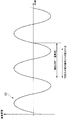
図7は、磁極位置検出部25が検出する磁極位置の移動の周期の一例を示す図である。MCU17は、磁極位置検出部25から供給される磁極位置を示す信号を、磁極位置の判定に用いる信号として取得するか否かを、磁極位置検出部25が検出する磁極位置の移動の周期に基づいて判定する。この図において、電気角1周期に要する時間は、ロータ24の回転数の変化に応じて変化する。具体的には、電気角1周期に要する時間は、ロータ24が高速回転する場合、低速回転する場合に比べて短い。また、ロータ24の回転数の変化速度が所定範囲内であれば、電気角1周期に要する時間の変化も所定範囲内である。つまり、一例として、20000[r/m]程度以上で高速回転しているロータ24が数回転する程度の微小な時間内であれば、電気角1周期に要する時間の変化は、極めて小さい。したがって、MCU17は、電気角1周期に要する時間を算出することにより、算出したタイミングから微小な時間経過後における、電気角1周期に要する時間の幅を推定することができる。つまり、MCU17は、磁極位置を示す信号が、どのタイミングで発生するのかを推定することができる。MCU17は、磁極位置を示す信号のうち、推定した電気角1周期に要する時間の幅内のタイミングで発生した磁極位置を示す信号を、ノイズではないと判定する。MCU17は、ノイズではないと判定した磁極位置を示す信号を、磁極位置の判定に用いる信号として取得すると判定する。また、MCU17は、磁極位置を示す信号のうち、推定した電気角1周期に要する時間の幅外のタイミングで発生した磁極位置を示す信号を、ノイズであると判定する。MCU17は、ノイズであると判定した磁極位置を示す信号を、磁極位置の判定に用いる信号として取得しないと判定する。
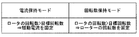
また、MCU17は、磁極位置検出部25が検出する磁極位置の移動の周期と、ロータ24の目標回転数とに基づいて、ロータ24の回転数をフィードバック制御することもできる。例えば、MCU17は、図8に示した2つの動作モードのいずれかの動作モードによって動作する。図8は、MCU17の2つの動作モードを例示する図である。2つの動作モードは、例えば、電流保持モードと回転数保持モードである。MCU17の動作モードが電流保持モードの場合、MCU17は、巻線21、巻線22、巻線23のそれぞれに供給される電流値のフィードバックによりロータ24の回転数を制御する。具体的には、巻線21、巻線22、巻線23に供給される電流値は、電流センサ(不図示)により検出される。この場合、MCU17は、電流センサが検出する巻線21、巻線22、巻線23の電流値と、目標電流値との差分に基づいて、巻線21、巻線22、巻線23に供給する電流値を算出する。また、MCU17は、算出した電流値の電流を巻線21、巻線22、巻線23に供給する。
また、MCU17の動作モードが回転数保持モードの場合、MCU17は、ロータ24の回転数のフィードバックにより、ロータ24の回転数を制御する。具体的には、MCU17は、磁極位置検出部25により検出された磁極位置の変化周期に基づいて、ロータ24の回転数を算出する。また、MCU17は、算出したロータ24の回転数と、目標回転数との差分に基づいて、巻線21、巻線22、巻線23に供給する電圧波形を算出する。また、MCU17は、算出した電圧波形の電流を巻線21、巻線22、巻線23に供給する。MCU17は、これらの回転数の制御を、磁極位置検出部25が検出する磁極位置の移動の周期が示すロータ24の回転数が、操作検出部が検出する操作に対応する目標回転数を超える場合に行う。すなわち、制御部16は、磁極位置検出部25が検出する磁極位置の移動の周期が示すロータ24の回転数が、操作検出部が検出する操作に対応する目標回転数を超える場合には、ロータ24の回転数のフィードバックにより、又は巻線21、22、23に供給される電流値のフィードバックによりロータ24の回転数を制御する。これにより、直流ブラシレスモータ制御装置15は、フィードバックにより、ロータ24の回転数が目標上限値である目標回転数から意図せずに上昇してしまうことによる発熱を抑制することができる。
また、MCU17の動作モードが回転数保持モードの場合、MCU17は、ロータ24の回転数のフィードバックにより、ロータ24の回転数を制御する。具体的には、MCU17は、磁極位置検出部25により検出された磁極位置の変化周期に基づいて、ロータ24の回転数を算出する。また、MCU17は、算出したロータ24の回転数と、目標回転数との差分に基づいて、巻線21、巻線22、巻線23に供給する電圧波形を算出する。また、MCU17は、算出した電圧波形の電流を巻線21、巻線22、巻線23に供給する。MCU17は、これらの回転数の制御を、磁極位置検出部25が検出する磁極位置の移動の周期が示すロータ24の回転数が、操作検出部が検出する操作に対応する目標回転数を超える場合に行う。すなわち、制御部16は、磁極位置検出部25が検出する磁極位置の移動の周期が示すロータ24の回転数が、操作検出部が検出する操作に対応する目標回転数を超える場合には、ロータ24の回転数のフィードバックにより、又は巻線21、22、23に供給される電流値のフィードバックによりロータ24の回転数を制御する。これにより、直流ブラシレスモータ制御装置15は、フィードバックにより、ロータ24の回転数が目標上限値である目標回転数から意図せずに上昇してしまうことによる発熱を抑制することができる。
ここで、操作検出部が検出する操作は、この一例において、吸引装置の吸引力の段階を選択する操作である。つまり、吸引装置に対する操作とは、吸引装置の吸引力の段階を選択する操作である。記憶部には、図6に示したように、ロータ24の目標回転数を示す情報が、操作検出部が検出する操作が示す吸引装置1の吸引力の段階に対応する複数の段階の回転数に区切られて記憶されている。MCU17は、操作検出部が検出した操作に応じた吸引力の段階に対応する段階の目標回転数を示す情報を記憶部12から読み出す。MCU17は、ロータ24の回転数を、読み出した目標回転数に一致させる。これにより、直流ブラシレスモータ制御装置15は、吸引力に基づく吸引装置1の操作をユーザに提供することができる。なお、吸引装置1は、吸引装置の一例である。
1…吸引装置、12…記憶部、13…操作スイッチ、15…直流ブラシレスモータ制御装置、16…制御部、17…MCU、18…ドライバー、20…三相直流ブラシレスモータ、21、22、23…巻線、24…ロータ、25、25-1、25-2、25-3…磁極位置検出部、29…整流部、30…昇圧部、31…第1DC-DCコンバーター、32…第2DC-DCコンバーター、40…三相ブリッジインバータ部、241…永久磁石、411、412、421、422、431、432…電界効果トランジスタ
Claims (4)
- 吸引装置の吸引ファンを回転させる三相直流ブラシレスモータの固定子の巻線に対して電流を供給する直流ブラシレスモータ制御装置であって、
スイッチング素子どうしが直列接続され、かつ前記スイッチング素子どうしの接続点と前記巻線の一端とが接続されたアームを、各相に備える三相ブリッジインバータ部と、
前記三相直流ブラシレスモータのロータの磁極位置を検出する磁極位置検出部が検出する前記磁極位置に基づいて、前記アームが備える前記スイッチング素子のうち、前記接続点の一方側にある第1スイッチング素子の通電状態と、他方側にある第2スイッチング素子の通電状態とを、それぞれ制御することにより、前記ロータの回転数を制御する制御部と、
前記吸引装置に対する操作を検出する操作検出部と、
前記ロータの目標回転数を示す情報が、前記操作検出部が検出する操作に対応する複数の段階の回転数に区切られて記憶されている記憶部と、
を備え、
前記制御部は、
前記磁極位置検出部が検出する前記磁極位置の移動の周期が示す前記ロータの回転数が、前記操作検出部が検出する操作に対応する前記目標回転数を超える場合には、前記ロータの回転数のフィードバックにより、又は前記巻線に供給される電流値のフィードバックにより前記ロータの回転数を制御する。 - 請求項1に記載の直流ブラシレスモータ制御装置であって、
前記吸引装置に対する操作とは、前記吸引装置の吸引力の段階を選択する操作であり、
前記記憶部には、前記ロータの目標回転数を示す情報が、前記操作検出部が検出する操作が示す前記吸引装置の吸引力の段階に対応する複数の段階の回転数に区切られて記憶されている。 - 請求項1又は請求項2に記載の直流ブラシレスモータ制御装置であって、
前記制御部は、
前記三相直流ブラシレスモータに電力を供給する二次電池の残量に基づいて、前記ロータの回転数を制御する。 - 請求項3に記載の直流ブラシレスモータ制御装置であって、
前記制御部は、
前記二次電池の残量が所定のしきい値未満である場合に、前記ロータの回転数を前記記憶部に記憶されている目標回転数から低減して前記ロータの回転数を制御し、前記二次電池の残量が所定のしきい値以上である場合に、前記ロータの回転数を前記記憶部に記憶されている目標回転数によって前記ロータの回転数を制御する。
Priority Applications (4)
| Application Number | Priority Date | Filing Date | Title |
|---|---|---|---|
| EP16803271.2A EP3306807A4 (en) | 2015-05-29 | 2016-05-27 | CONTROL UNIT FOR BRUSHLESS DC MOTOR |
| JP2017521914A JPWO2016194836A1 (ja) | 2015-05-29 | 2016-05-27 | 直流ブラシレスモータ制御装置 |
| US15/575,925 US20180152122A1 (en) | 2015-05-29 | 2016-05-27 | Dc-brushless-motor control device |
| CN201680034315.5A CN107710593A (zh) | 2015-05-29 | 2016-05-27 | 直流无刷马达控制装置 |
Applications Claiming Priority (2)
| Application Number | Priority Date | Filing Date | Title |
|---|---|---|---|
| US201562168139P | 2015-05-29 | 2015-05-29 | |
| US62/168139 | 2015-05-29 |
Publications (1)
| Publication Number | Publication Date |
|---|---|
| WO2016194836A1 true WO2016194836A1 (ja) | 2016-12-08 |
Family
ID=57442359
Family Applications (1)
| Application Number | Title | Priority Date | Filing Date |
|---|---|---|---|
| PCT/JP2016/065781 Ceased WO2016194836A1 (ja) | 2015-05-29 | 2016-05-27 | 直流ブラシレスモータ制御装置 |
Country Status (5)
| Country | Link |
|---|---|
| US (1) | US20180152122A1 (ja) |
| EP (1) | EP3306807A4 (ja) |
| JP (1) | JPWO2016194836A1 (ja) |
| CN (1) | CN107710593A (ja) |
| WO (1) | WO2016194836A1 (ja) |
Families Citing this family (2)
| Publication number | Priority date | Publication date | Assignee | Title |
|---|---|---|---|---|
| JP2020000600A (ja) * | 2018-06-29 | 2020-01-09 | パナソニックIpマネジメント株式会社 | 電気掃除機 |
| CN116209381A (zh) * | 2020-08-03 | 2023-06-02 | 创科无线普通合伙 | 具有低功率模式的地板清洁器 |
Citations (4)
| Publication number | Priority date | Publication date | Assignee | Title |
|---|---|---|---|---|
| JP2000069787A (ja) * | 1998-08-25 | 2000-03-03 | Sharp Corp | 電気掃除機 |
| JP2002153083A (ja) * | 2000-08-29 | 2002-05-24 | Toshiba Tec Corp | 電気掃除機用電動送風機のインバータ制御回路、これを用いた駆動制御回路及びこの駆動制御回路を用いた電気掃除機 |
| JP2003000503A (ja) * | 2001-06-26 | 2003-01-07 | Matsushita Electric Ind Co Ltd | 電気掃除機 |
| JP2010057647A (ja) * | 2008-09-03 | 2010-03-18 | Hitachi Appliances Inc | 電気掃除機 |
Family Cites Families (9)
| Publication number | Priority date | Publication date | Assignee | Title |
|---|---|---|---|---|
| EP0479609A3 (en) * | 1990-10-05 | 1993-01-20 | Hitachi, Ltd. | Vacuum cleaner and control method thereof |
| JPH0658607A (ja) * | 1992-08-11 | 1994-03-04 | Fujitsu General Ltd | 空気調和機の制御方法 |
| JP2002000524A (ja) * | 2000-06-20 | 2002-01-08 | Hitachi Ltd | 電気掃除機 |
| JP3658310B2 (ja) * | 2000-11-16 | 2005-06-08 | 東芝テック株式会社 | Pwm制御回路、電動送風機及び電気掃除機 |
| JP2003169490A (ja) * | 2001-12-03 | 2003-06-13 | Mitsubishi Heavy Ind Ltd | 電動機制御システム、電動機制御装置、及び電動機駆動用インバータ制御方法 |
| US7049786B1 (en) * | 2002-11-25 | 2006-05-23 | The Texas A&M University System | Unipolar drive topology for permanent magnet brushless DC motors and switched reluctance motors |
| JP4079962B2 (ja) * | 2005-08-30 | 2008-04-23 | 株式会社東芝 | 電気掃除機 |
| JP4466599B2 (ja) * | 2006-03-31 | 2010-05-26 | アイシン・エィ・ダブリュ株式会社 | 電動駆動制御装置及び電動駆動制御方法 |
| JP4353304B2 (ja) * | 2008-02-19 | 2009-10-28 | トヨタ自動車株式会社 | モータ駆動制御装置 |
-
2016
- 2016-05-27 EP EP16803271.2A patent/EP3306807A4/en not_active Withdrawn
- 2016-05-27 CN CN201680034315.5A patent/CN107710593A/zh not_active Withdrawn
- 2016-05-27 WO PCT/JP2016/065781 patent/WO2016194836A1/ja not_active Ceased
- 2016-05-27 US US15/575,925 patent/US20180152122A1/en not_active Abandoned
- 2016-05-27 JP JP2017521914A patent/JPWO2016194836A1/ja active Pending
Patent Citations (4)
| Publication number | Priority date | Publication date | Assignee | Title |
|---|---|---|---|---|
| JP2000069787A (ja) * | 1998-08-25 | 2000-03-03 | Sharp Corp | 電気掃除機 |
| JP2002153083A (ja) * | 2000-08-29 | 2002-05-24 | Toshiba Tec Corp | 電気掃除機用電動送風機のインバータ制御回路、これを用いた駆動制御回路及びこの駆動制御回路を用いた電気掃除機 |
| JP2003000503A (ja) * | 2001-06-26 | 2003-01-07 | Matsushita Electric Ind Co Ltd | 電気掃除機 |
| JP2010057647A (ja) * | 2008-09-03 | 2010-03-18 | Hitachi Appliances Inc | 電気掃除機 |
Non-Patent Citations (1)
| Title |
|---|
| See also references of EP3306807A4 * |
Also Published As
| Publication number | Publication date |
|---|---|
| JPWO2016194836A1 (ja) | 2018-03-22 |
| EP3306807A1 (en) | 2018-04-11 |
| US20180152122A1 (en) | 2018-05-31 |
| EP3306807A4 (en) | 2019-02-13 |
| CN107710593A (zh) | 2018-02-16 |
Similar Documents
| Publication | Publication Date | Title |
|---|---|---|
| US11682988B2 (en) | Method for controlling an electric motor | |
| JP5524925B2 (ja) | 電気機械の制御方法 | |
| JP5882023B2 (ja) | ファン制御装置 | |
| JP2013179833A (ja) | 電動圧縮機および家庭用電気機器 | |
| JP2008188264A (ja) | モータ駆動装置及びそれを用いた電気掃除機 | |
| JP5879712B2 (ja) | 電動工具 | |
| EP2790316A2 (en) | Sensorless control apparatus and method of washing machine | |
| EP3306804A1 (en) | Dc-brushless-motor control device | |
| JP5903551B2 (ja) | インバータ制御装置と電動圧縮機および電気機器 | |
| WO2016194836A1 (ja) | 直流ブラシレスモータ制御装置 | |
| JP5412928B2 (ja) | インバータ制御装置と電動圧縮機および家庭用電気機器 | |
| JP4927521B2 (ja) | 電気掃除機 | |
| US20180152080A1 (en) | Dc-brushless-motor control device | |
| JP5326948B2 (ja) | インバータ制御装置と電動圧縮機および電気機器 | |
| JP2010259184A (ja) | インバータ制御装置と電動圧縮機および家庭用電気機器 | |
| JP2012130091A (ja) | ファン制御装置、ファン制御方法および冷凍サイクルシステム | |
| JP5863473B2 (ja) | モータ駆動装置 | |
| KR102187749B1 (ko) | 모터 구동장치 및 이를 구비하는 홈 어플라이언스 | |
| US8723464B2 (en) | Permanent magnet motor system | |
| JP2012105384A (ja) | インバータ制御装置、それを用いた電動圧縮機および家庭用電気機器 | |
| JP2014003833A (ja) | インバータ制御装置と電動圧縮機および電気機器 |
Legal Events
| Date | Code | Title | Description |
|---|---|---|---|
| 121 | Ep: the epo has been informed by wipo that ep was designated in this application |
Ref document number: 16803271 Country of ref document: EP Kind code of ref document: A1 |
|
| WWE | Wipo information: entry into national phase |
Ref document number: 15575925 Country of ref document: US |
|
| ENP | Entry into the national phase |
Ref document number: 2017521914 Country of ref document: JP Kind code of ref document: A |
|
| NENP | Non-entry into the national phase |
Ref country code: DE |