WO2016194898A1 - 直流電流遮断装置 - Google Patents
直流電流遮断装置 Download PDFInfo
- Publication number
- WO2016194898A1 WO2016194898A1 PCT/JP2016/066018 JP2016066018W WO2016194898A1 WO 2016194898 A1 WO2016194898 A1 WO 2016194898A1 JP 2016066018 W JP2016066018 W JP 2016066018W WO 2016194898 A1 WO2016194898 A1 WO 2016194898A1
- Authority
- WO
- WIPO (PCT)
- Prior art keywords
- current
- circuit
- connection
- transmission line
- series
- Prior art date
- Legal status (The legal status is an assumption and is not a legal conclusion. Google has not performed a legal analysis and makes no representation as to the accuracy of the status listed.)
- Ceased
Links
Images



Classifications
-
- H—ELECTRICITY
- H01—ELECTRIC ELEMENTS
- H01H—ELECTRIC SWITCHES; RELAYS; SELECTORS; EMERGENCY PROTECTIVE DEVICES
- H01H9/00—Details of switching devices, not covered by groups H01H1/00 - H01H7/00
- H01H9/54—Circuit arrangements not adapted to a particular application of the switching device and for which no provision exists elsewhere
- H01H9/541—Contacts shunted by semiconductor devices
- H01H9/542—Contacts shunted by static switch means
-
- H—ELECTRICITY
- H01—ELECTRIC ELEMENTS
- H01H—ELECTRIC SWITCHES; RELAYS; SELECTORS; EMERGENCY PROTECTIVE DEVICES
- H01H9/00—Details of switching devices, not covered by groups H01H1/00 - H01H7/00
- H01H9/54—Circuit arrangements not adapted to a particular application of the switching device and for which no provision exists elsewhere
-
- H—ELECTRICITY
- H01—ELECTRIC ELEMENTS
- H01H—ELECTRIC SWITCHES; RELAYS; SELECTORS; EMERGENCY PROTECTIVE DEVICES
- H01H33/00—High-tension or heavy-current switches with arc-extinguishing or arc-preventing means
- H01H33/02—Details
- H01H33/59—Circuit arrangements not adapted to a particular application of the switch and not otherwise provided for, e.g. for ensuring operation of the switch at a predetermined point in the AC cycle
- H01H33/596—Circuit arrangements not adapted to a particular application of the switch and not otherwise provided for, e.g. for ensuring operation of the switch at a predetermined point in the AC cycle for interrupting DC
Definitions
- Embodiments of the present invention relate to a DC current interrupting device suitable for a DC power transmission network.
- DC power transmission is more efficient than conventional three-phase AC power transmission and can be installed with reduced costs. Being started.
- DC power transmission requires a power converter such as a converter that converts the generated AC power into DC for DC power transmission and an inverter that converts the transmitted DC power into city AC.
- a power converter such as a converter that converts the generated AC power into DC for DC power transmission and an inverter that converts the transmitted DC power into city AC.
- the modular multi-level converter circuit that can output a voltage waveform close to a sine wave is being studied and put into practical use so that harmonics accompanying switching of the converter and inverter do not flow into the AC system.
- the DC power transmission system can be installed at low cost when compared to the conventional AC power transmission system, and it can be constructed at a low cost, and a high-efficiency system with less transmission loss can be constructed. On the other hand, it is difficult to block the location where the system accident caused by lightning strikes.
- the AC current can be cut off at high speed by a mechanical contact breaker at a timing at which the AC current crosses zero current every half cycle at an AC frequency of 50 [Hz] or 60 [Hz].
- a mechanical contact cannot easily interrupt the current.
- a large current always flows through the transmission line, so that a large conduction loss in the semiconductor element is constantly consumed.
- FIG. 6A is a diagram showing a circuit configuration of the DC current interrupting device 4, and FIG. 6B is a specific circuit element configuration of the commutation circuit (H) 31 in FIG. 6A.
- FIG. 6B is a specific circuit element configuration of the commutation circuit (H) 31 in FIG. 6A.
- FIG. 6 only the positive line of the DC transmission line is shown, and the negative line is omitted.
- the positive electrode line is shown in the figure, and the negative electrode line is omitted.
- This DC current interrupting device 4 has a circuit configuration in which two series circuits 2 constituted by two mechanical contact type current disconnectors 21 are connected in parallel, and their midpoints are connected by a connection circuit 3 constituted by a commutation circuit 31. .
- the commutation circuit 31 has a single-phase full bridge configuration using a capacitor as a DC voltage source.
- the DC current interrupting device 4 is inserted in series at a required location in the transmission line 11 of the DC transmission network.
- the two mechanical contact type current disconnectors 21 on the diagonal are turned off, and the current is kept on by using the two mechanical contact type current disconnectors 21. It is made to flow with current circuit 31 and mechanical contact type current disconnector 21. Then, the current flowing through the commutation circuit 31 is controlled to zero, and the two mechanical contact type current disconnectors 21 remaining at the moment when the current flowing through the mechanical contact type current disconnector 21 becomes zero are turned off. As a result, the accident current is interrupted.
- the number of parts increases as a whole system, and the increase in the number of parts leads to an increase in cost and an increase in the size of the apparatus.
- each of two different DC transmission lines is connected.
- One end connected to the middle point of each series circuit and three or more series circuits including a series connection of two or more current disconnectors connected to the end, and the other ends all connected to each other at one point
- a DC current interrupting device including three or more connection circuits including a commutation circuit that commutates current.
- each of two different DC transmission lines is provided.
- One end is connected to the middle point of each of the three or more series circuits including the series connection of two or more elements including commutation means connected to the end of the electric wire, and the other ends are all one point.
- a DC current interrupting device is provided that includes three or more connection circuits including current disconnectors connected to each other.
- FIG. 1 is a diagram showing a configuration of a DC current interrupting device according to a first embodiment of the present invention.
- the DC current interrupting device is provided at a coupling point where the three DC transmission lines 11, 12, and 13 are electrically coupled.
- the direct current transmission lines 11, 12, and 13 are connected to each other by a series circuit 2 including two mechanical contact type current disconnectors 21.
- the series circuit 2 is configured to connect points a, b, and c on the line in a delta connection.
- connection circuit 3 including the commutation circuit (H) 31 is connected to the middle point of the two mechanical contact type current disconnectors 21 of each series circuit 2, and the other end of each connection circuit 3. Are all connected to each other at a contact j.
- connection circuits 3 correspond to a star connection.
- the commutation circuit 31 has a single-phase full-bridge configuration using a capacitor as a voltage source. All of the mechanical contact type current disconnectors 21 of the series circuit 2 are controlled to be turned on / off by a control circuit (not shown) according to the steady operation and the occurrence of execution on any of the power transmission lines. The output voltage of the commutation circuit 31 of the connection circuit 3 is also controlled by the control circuit.
- the control circuit turns on the mechanical contact type current disconnectors 21 in all the series circuits 2 so that the current is transmitted through the mechanical contact type current disconnectors 21.
- the control circuit turns off the pair of mechanical contact type current disconnectors 2a sandwiching the contact j as shown in FIG. It flows through the flow circuit 31 and the mechanical contact type current disconnector 2b.
- control circuit controls the output voltage and the amount of current so that the fault current if in the commutation circuit 31 becomes zero.
- the mechanical contact type current disconnector 2b in which the accident current if flows is turned off to turn off the DC transmission line where the accident has occurred. 13 is blocked.
- the configuration of the series circuit 2 is compared with the case where the conventional DC current interrupting device shown in FIG. 6 is individually connected to each of the DC power transmission lines 11, 12, and 13.
- a direct current interrupting device capable of reducing the cost and size can be realized by reducing the scale by half and by reducing the total number of parts.
- a semiconductor breaker can perform the same operation.
- one mechanical contact type current disconnecting device 21 is arranged in each series circuit 2 with the middle point in between, but the series circuit 2 has the mechanical contact type current disconnecting device 21 in the middle point.
- a configuration in which a plurality of them are connected in series may be used.
- a plurality of the commutation circuits 31 may be connected in series to form the connection circuit 3. If the current control direction of the commutation circuit 31 is limited, a half bridge circuit may be used.
- a reactor may exist in series on the line connecting the points a, b, and c.
- the reactor suppresses the peak of the alternating current that flows in the event of an accident, lowers the frequency of the alternating current, and consequently lowers the slope of the alternating current, thereby facilitating current interruption in the mechanical contact type current disconnector 21. You can also.
- FIG. 3 is a diagram illustrating a configuration of the DC current interrupting device according to the second embodiment.
- the basic concept is the same as the configuration shown in FIG. 1, the same or equivalent components as those of the DC current interrupting device shown in FIG. The description will be given with the same reference numerals.
- This embodiment is a configuration example of a DC current interrupting device at a connection point of four DC transmission lines 11 to 14. At the connection point, two adjacent DC transmission lines 11 to 14 are connected by a series circuit 2 including two mechanical contact type current disconnectors 21.
- connection circuit 3 including the commutation circuit (H) 31 is connected to the middle point of the two mechanical contact type current disconnectors 21 of each series circuit 2, and the other end of each of the connection circuits 3 is connected All are connected to each other at the contact j.
- the commutation circuit 31 has a single-phase full-bridge configuration using a capacitor as a voltage source as shown in FIG. All of the mechanical contact type current disconnectors 21 of the series circuit 2 are controlled to be turned on / off by a control circuit (not shown) according to the steady operation and the occurrence of execution on any of the power transmission lines.
- the output voltage of the commutation circuit 31 of the connection circuit 3 is also controlled by the control circuit.
- the current interruption operation of the DC current interruption device is the same as that of the first embodiment, and even if an accident occurs in any of the DC transmission lines 11 to 14, the DC transmission line in which the accident has occurred can be quickly It is possible to detach.
- the number of components of the series circuit 2 can be halved compared to the case where the conventional DC current interrupting device shown in FIG. 6 is individually connected to each of the DC power transmission lines 11 to 14. As a result, it is possible to realize a direct current interrupting device that can reduce the number of parts, reduce the cost, and reduce the size.
- the series circuit 2 can be realized by n half of the series circuit 2.
- the number of parts can be halved from the conventional one by also configuring the connection points of five or more DC transmission lines in the same manner as in the present embodiment.
- the DC power transmission line 11 is connected to the DC power transmission lines 13 and 14 through the series circuit 2.
- the DC power transmission lines 12 and 13 or the DC power transmission lines 12 and 14 may be connected to the power transmission line 11. The same applies to other DC transmission lines.
- FIG. 4 is a diagram illustrating a configuration of a DC current interrupting device according to the third embodiment.
- the basic concept is the same as the configuration shown in FIG. 1, the same or equivalent components as those of the DC current interrupting device shown in FIG. The description will be given with the same reference numerals.
- the DC current interrupting device has DC power transmission lines 11, 12, 13 respectively at the connection points where the three DC power transmission lines 11, 12, 13 are electrically coupled. Are connected to each other by a series circuit 2 including a reactor 22 and a semiconductor circuit breaker 23.
- each semiconductor circuit breaker 23 has a configuration in which two semiconductor switching elements 231 are connected in series so as to face in opposite directions, and an arrester 232 is connected in parallel thereto.
- the series circuit 2 has a configuration in which the points a, b, and c on the line are delta-connected at the connection point of the three DC transmission lines 11, 12, and 13. And one end of the connection circuit 3 provided with the mechanical contact-type current disconnector 32 is respectively connected to the midpoint of the reactor 22 and the semiconductor circuit breaker 23 of the series circuit 2, and all the other ends of the connection circuit 3 are contact points. j connected to each other. This corresponds to a star connection.
- All of the semiconductor circuit breakers 23 of the series circuit 2 are controlled to be turned on / off by a control circuit (not shown) in accordance with the steady operation and the occurrence of execution on any of the power transmission lines.
- the mechanical contact type current disconnector 32 of the connection circuit 3 is also controlled to be turned on / off by the control circuit.
- an accident current if flows toward the DC transmission line where the accident occurred.
- the control circuit detects an accident, it turns on the semiconductor circuit breaker 23 connected to the DC power transmission line where the accident occurred. Then, the accident current if is commutated from the reactor 22 connected to the DC transmission line where the accident has occurred and the mechanical contact type current disconnector 32 to the semiconductor breaker 23 that is turned on. At that time, since the timing when the mechanical contact type current disconnector 32 becomes zero current occurs, the mechanical contact type current disconnector 32 is turned off by the control circuit at that moment. Next, the semiconductor circuit breaker 23 in which the fault current is commutated is turned off. As a result, the DC transmission line where the accident occurred is blocked.
- the configuration of the series circuit 2 is compared with the case where the conventional DC current interrupting device shown in FIG. 6 is individually connected to each of the DC power transmission lines 11, 12, and 13.
- a direct current interrupting device capable of reducing the cost and size can be realized by reducing the scale by half and by reducing the total number of parts.
- each element may be configured to face only one direction.
- the arrester 232 may be connected in parallel to the individual semiconductor switching elements 231 or in parallel to the plurality of semiconductor switching elements 231, or a plurality of semiconductor circuit breakers 23 themselves may be connected in series.
- the same configuration can be applied to a DC current interrupting device at a connection point of four or more DC transmission lines.
- FIG. 5 is a diagram illustrating a configuration of a DC current interrupting device according to the fourth embodiment.
- the basic concept is the same as the configuration shown in FIG. 1, the same or equivalent components as those of the DC current interrupting device shown in FIG. The description will be given with the same reference numerals.
- This DC current interrupting device is configured such that each series circuit 2 is connected to two reactors 22 and two semiconductor circuit breakers 23 alternately. One end of each mechanical contact type current disconnector 32 is connected to the middle point e, f, g of each series circuit 2, and the other end of the mechanical contact type current disconnector 32 is all connected to each other at a contact j. Yes.
- a mechanical contact type current disconnector 33 is connected to the junction of the reactor 22 and the semiconductor circuit breaker 23 that are not connected to the midpoints e, f, and g of the series circuit 2.
- the other end of 33 is connected to the junction of the reactor 22 and the semiconductor circuit breaker 23 of the adjacent series circuit 2.
- the mechanical contact type current disconnector 33 connects the junction points of the reactor 22 and the semiconductor circuit breaker 23 belonging to each series circuit 2 branched into two from the same DC transmission line.
- All of the semiconductor circuit breakers 23 of the series circuit 2 are controlled to be turned on / off by a control circuit (not shown) in accordance with the steady operation and the occurrence of execution on any of the power transmission lines.
- the on / off operation of the mechanical contact type current disconnectors 32 and 33 of the connection circuit 3 is also controlled by the control circuit.
- the operation at the time of current interruption of the DC current interruption device according to this embodiment is the same as that of the third embodiment, and even if an accident occurs in any DC transmission line, the DC transmission line in which the accident has occurred is disconnected.
- the voltage applied to the mechanical contact type current disconnectors 32 and 33 is lower than that of the configuration of the third embodiment, the required insulation resistance is reduced. Then, since the insulation distance is shortened and the mechanical contact type current disconnectors 32 and 33 having a low switching speed and a low price can be used, it is possible to construct a DC current interrupting device capable of further reducing the cost.
- the bridge circuit formed by the series circuit 2 and the connection circuit 3 can be further multi-staged.
- the current interruption operation of the DC current interruption device in that case is the same as that of the fourth embodiment, and even if an accident occurs in any DC transmission line, the DC transmission line in which the accident has occurred can be disconnected in a short time. Is possible.
- the DC current interruption can be further reduced by using a slower and cheaper mechanical contact type current disconnector. It is also possible to construct a device.
- a DC current interrupting device can be configured similarly.
- the series circuit 2 and the connection circuit 3 shown in FIG. 5 can be replaced with the series circuit 2 and the connection circuit 3 shown in FIG. 1, respectively.
- the series circuit 2 may have a configuration in which, for example, four or more mechanical contact type current disconnectors 21 are directly connected.
Landscapes
- Engineering & Computer Science (AREA)
- Power Engineering (AREA)
- Driving Mechanisms And Operating Circuits Of Arc-Extinguishing High-Tension Switches (AREA)
- Keying Circuit Devices (AREA)
Abstract
実施形態によれば、直流送電線網の中で3つ以上の直流送電線(11~13)が電気的に結合される結合点に設置される直流電流遮断装置が提供される。直流電流遮断装置は、それぞれが、異なる2つの直流送電線の端部と接続され、2つ以上の電流断路器(21)の直列接続を含む、3つ以上の直列回路(2)と、各直列回路の中点に一端が接続され、他端が全て1点で互いに接続された、電流を転流する転流回路(31)を含む、3つ以上の結線回路(3)とを備える。
Description
本発明の実施形態は、直流送電網に好適な直流電流遮断装置に関する。
近年、風力発電や太陽光発電、太陽熱発電などの再生可能エネルギーの普及が促進されている。より大電力を再生可能エネルギーでまかなうために、洋上風力発電や、砂漠地帯での太陽光、太陽熱発電が検討され始めている。
洋上風力発電においては、発電された電力を消費地である都市まで海底ケーブルで大電力送電する必要があり、また太陽光発電、太陽熱発電では、アフリカや中国奥部の砂漠地帯から、ヨーロッパや沿岸地帯の大都市まで大電力を長距離にわたって高効率に送電することが必要になる。
このような長距離送電の要求には、従来の3相交流による電力送電よりも、直流送電のほうが高効率で、コストを抑えながら設置することが可能になるため、直流送電網の構築が検討され始めている。
直流送電においては、発電された交流電力を直流送電用の直流に変換するコンバータや、送電されてきた直流を都市内の交流に変換するインバータなどの電力変換装置が必要になる。交流系統にコンバータ、インバータのスイッチングに伴う高調波が流出しないように、正弦波に近い電圧波形を出力することができるモジュラーマルチレベル変換器回路などの検討や実用化が進められている。
直流送電システムは、従来の交流送電システムに比べて、長距離大電力送電に適用した場合に、低コストで設置が可能で、送電損失が少ない高効率システムを構築することが可能であるが、その反面、落雷などに起因した系統事故が発生した個所を遮断することが難しい。
交流システムにおいては、交流電流が交流周波数50[Hz]または60[Hz]の半サイクル毎にゼロ電流を横切るタイミングで、機械接点式の遮断器により高速に電流遮断ができるのに対して、直流電流では電流がゼロを横切るタイミングがないので、機械式接点では電流を容易に遮断できない。半導体素子を介して電流を遮断する方法もあるが、送電線には常に大電流が流れるため、当該半導体素子での大きな導通損失が定常的に消費されることになる。
電力送電網を構築する場合、事故発生点を短時間のうちに送電網から切り離して健全な送電網だけで運転を継続することが求められており、そのために図6に示すような直流電流遮断装置が提案されている。
図6の(A)は直流電流遮断装置4の回路構成を示す図、図6の(B)は図6の(A)中の転流回路(H)31の具体的な回路素子構成を示す図である。
この図6においては直流送電線路の正極線のみを図示しており、負極線は省略している。以後、図においては正極線のみを示し、負極線は省略するものとする。
この直流電流遮断装置4は、2つの機械接点式電流断路器21による直列回路2を、2つ並列に接続し、その中点同士を転流回路31による結線回路3で接続した回路構成である。
さらに転流回路31は、コンデンサを直流電圧源とした単相フルブリッジ構成である。直流電流遮断装置4は直流送電網の送電線11中の所要個所に直列に挿入される。
この直流電流遮断装置4によれば、定常動作時には、全ての機械接点式電流断路器21は図6の(A)の状態とは反対にオンにする。この定常動作時において、通常の直流電流は機械接点式電流断路器21を通って流れる。
系統事故発生時には、対角上の2つの機械接点式電流断路器21をオフにし、電流は2つのオンを維持する機械接点式電流断路器21を用いて、機械接点式電流断路器21、転流回路31、機械接点式電流断路器21と流れるようにする。そして転流回路31が流れる電流をゼロに制御し、機械接点式電流断路器21に流れる電流がゼロとなった瞬間に残る2つの機械接点式電流断路器21をオフにする。これにより事故電流は遮断される。
しかしながら図6に示した直流電流遮断装置4では、図7のような複数、例えば3つの直流送電線11,12,13の結合点kにおいて、事故が起きた系統のみを遮断するために、各直流送電線11,12,13に対して1つずつ、前述の直流電流遮断装置4を配置する必要がある。
そのため、システム全体として部品点数が増加し、部品点数の増加はそのまま高コスト化、装置の大型化につながる。
このようなことから、複数の直流送電線の結合点において、事故電流を高速に遮断可能としながら、部品点数を低減し、低コストで小型化が可能な直流電流遮断装置を提供することが望まれる。
一実施形態によれば、直流送電線網の中で3つ以上の直流送電線が電気的に結合される結合点に設置される直流電流遮断装置において、それぞれが、異なる2つの直流送電線の端部と接続され、2つ以上の電流断路器の直列接続を含む、3つ以上の直列回路と、各直列回路の中点に一端が接続され、他端が全て1点で互いに接続された、電流を転流する転流回路を含む、3つ以上の結線回路と、を備える直流電流遮断装置が提供される。
また、他の実施形態によれば、直流送電線網中で3つ以上の直流送電線が電気的に結合される結合点に設置される直流電流遮断装置において、それぞれが、異なる2つの直流送電線の端部と接続され、転流手段を含む2つ以上の要素の直列接続を含む、3つ以上の直列回路と、各直列回路の中点に一端が接続され、他端が全て1点で互いに接続された電流断路器を含む、3つ以上の結線回路と、を備える直流電流遮断装置が提供される。
以下、本発明の実施形態について、図面を参照して詳細に説明する。
(第1の実施形態)
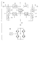
図1は、本発明の第1の実施形態に係る直流電流遮断装置の構成を示す図である。
図1の(A)に示すように直流電流遮断装置は、3本の直流送電線11,12,13が電気的に結合する結合点に設けられる。直流送電線11,12,13それぞれの線路を互いに、2つの機械接点式電流断路器21からなる直列回路2で接続する。これら3つの直流送電線11,12,13の結合点において、直列回路2は線路上の点a,b,cをデルタ結線する構成となる。
(第1の実施形態)
図1は、本発明の第1の実施形態に係る直流電流遮断装置の構成を示す図である。
図1の(A)に示すように直流電流遮断装置は、3本の直流送電線11,12,13が電気的に結合する結合点に設けられる。直流送電線11,12,13それぞれの線路を互いに、2つの機械接点式電流断路器21からなる直列回路2で接続する。これら3つの直流送電線11,12,13の結合点において、直列回路2は線路上の点a,b,cをデルタ結線する構成となる。
そして、各直列回路2の2つの機械接点式電流断路器21の中点には、それぞれ転流回路(H)31を含んだ結線回路3の一端が接続され、これら各結線回路3の他端が全て接点jにて互いに接続される。これら結線回路3はスター結線に相当する。
図1の(B)に示すように、転流回路31はコンデンサを電圧源とした単相フルブリッジ構成である。
前記直列回路2の機械接点式電流断路器21の全てが、ここでは図示しない制御回路により定常動作時及びいずれかの送電線での実行発生時に応じてオン/オフ動作が制御される。
また前記結線回路3の転流回路31も、前記制御回路により出力電圧が制御される。
前記直列回路2の機械接点式電流断路器21の全てが、ここでは図示しない制御回路により定常動作時及びいずれかの送電線での実行発生時に応じてオン/オフ動作が制御される。
また前記結線回路3の転流回路31も、前記制御回路により出力電圧が制御される。
次に、本実施形態に係る直流電流遮断装置の電流遮断時の動作を説明する。
定常動作時は、前記制御回路により全ての直列回路2で機械接点式電流断路器21をオンとさせ、電流が機械接点式電流断路器21を通じて伝送されるようにする。
定常動作時は、前記制御回路により全ての直列回路2で機械接点式電流断路器21をオンとさせ、電流が機械接点式電流断路器21を通じて伝送されるようにする。
図2の(A)に示すように、1本の直流送電線、例えば直流送電線13で事故が発生すると、その直流送電線13に向かって事故電流ifが流れる。事故を検出すると前記制御回路では、図2の(B)に示すように接点jを挟んだ一対の機械接点式電流断路器2aをオフさせ、事故電流ifが機械接点式電流断路器21、転流回路31、機械接点式電流断路器2bを通じて流れるようにする。
ここで前記制御回路は、転流回路31での事故電流ifがゼロになるよう、出力電圧を制御し、電流量を制御させる。そして、ゼロ電流となった時点で、図2の(C)に示すように、前記事故電流ifが流れていた機械接点式電流断路器2bをオフにさせることで、事故が発生した直流送電線13が遮断される。
事故が直流送電線13以外の他の系統の直流送電線11または12,13で発生した場合でも、同様に処理を行なうことで、直流送電線11または12で事故が起きた場合でも、事故が起きた直流送電線を切り離すことが可能となる。
以上に述べた如く本実施形態によれば、直流送電線11,12,13それぞれに個別に、図6で示した従来の直流電流遮断装置を接続した場合と比較して、直列回路2の構成規模を半分に削減することができ、ひいては全体の部品点数を低減して、低コスト化と小型化とが可能な直流電流遮断装置を実現できる。
なお本実施形態及び以下第2の実施形態以下において共通する事項についても述べておく。
前記機械接点式電流断路器21に代えて、半導体遮断器でも同様の動作が可能である。
図1では、各直列回路2において中点を挟んで機械接点式電流断路器21がそれぞれ1つずつ配置されているが、それら直列回路2は機械接点式電流断路器21を中点を挟んでそれぞれ複数直列接続した構成であっても良い。
また前記転流回路31は、複数直列接続して結線回路3を構成しても良い。また転流回路31の電流制御方向を限定するのであれば、ハーフブリッジ回路による構成でも構わない。
例えば点a,b,cを結線する線路上には、リアクトルが直列に存在していても構わない。このリアクトルにより、事故時に流れる交流電流のピークを抑制すると共に、交流電流の周波数を低くし、ひいては交流電流の傾きを低くすることで、機械接点式電流断路器21での電流遮断を容易にすることもできる。
(第2の実施形態)
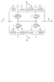
図3は、第2の実施形態に係る直流電流遮断装置の構成を示す図である。なお、以下において、図1に示した構成と基本的な考え方は同様であるため、図1に示す直流電流遮断装置の構成要素と同一または相当する構成要素には、図1で使用した符号と同一の符号を付して説明するものとする。
図3は、第2の実施形態に係る直流電流遮断装置の構成を示す図である。なお、以下において、図1に示した構成と基本的な考え方は同様であるため、図1に示す直流電流遮断装置の構成要素と同一または相当する構成要素には、図1で使用した符号と同一の符号を付して説明するものとする。
本実施形態は、4つの直流送電線11~14の結合点における直流電流遮断装置の構成例である。前記結合点において、直流送電線11~14それぞれの線路で互いに隣り合う2本の間を、2つの機械接点式電流断路器21からなる直列回路2で接続する。
そして、各直列回路2の2つの機械接点式電流断路器21の中点に、それぞれ転流回路(H)31を含んだ結線回路3の一端を接続し、これら各結線回路3の他端を全て接点jにて互いに接続する。
転流回路31は、図1の(B)で示したようにコンデンサを電圧源とした単相フルブリッジ構成である。
前記直列回路2の機械接点式電流断路器21の全てが、ここでは図示しない制御回路により定常動作時及びいずれかの送電線での実行発生時に応じてオン/オフ動作が制御される。
また前記結線回路3の転流回路31も、前記制御回路により出力電圧が制御される。
前記直列回路2の機械接点式電流断路器21の全てが、ここでは図示しない制御回路により定常動作時及びいずれかの送電線での実行発生時に応じてオン/オフ動作が制御される。
また前記結線回路3の転流回路31も、前記制御回路により出力電圧が制御される。
本直流電流遮断装置の電流遮断動作は、前記第1の実施形態と同様であり、直流送電線11~14のいずれかで事故が起きた場合でも、事故が起きた直流送電線を短時間で切り離すことが可能である。
本実施形態によれば、直流送電線11~14それぞれに個別に、図6に示した従来の直流電流遮断装置を接続する場合と比較して、直列回路2の構成数を半減させることができ、ひいては部品点数を低減し、低コスト化、小型化が可能な直流電流遮断装置を実現できる。
直流送電線がn本であるとき、図6で示した従来の直流電流遮断装置を接続する場合は、機械接点式電流断路器21の直列回路2が2n個必要となる。これに対し、本実施形態では直列回路2はその半分のn個で実現することが可能となる。
さらに5本以上の直流送電線の接合点においても、本実施形態と同様に構成することで、従来より部品点数を半減することができる。
なお図3では、例えば直流送電線11が直流送電線13,14とそれぞれ直列回路2で接続した構成としているが、直流送電線11~14は全て等価であるので、直列回路2を介して直流送電線11と接続されるのは、直流送電線12と13、または直流送電線12と14であっても構わない。また他の直流送電線についても同様である。
(第3の実施形態)
図4は、第3の実施形態に係る直流電流遮断装置の構成を示す図である。なお、以下において、図1に示した構成と基本的な考え方は同様であるため、図1に示す直流電流遮断装置の構成要素と同一または相当する構成要素には、図1で使用した符号と同一の符号を付して説明するものとする。
図4は、第3の実施形態に係る直流電流遮断装置の構成を示す図である。なお、以下において、図1に示した構成と基本的な考え方は同様であるため、図1に示す直流電流遮断装置の構成要素と同一または相当する構成要素には、図1で使用した符号と同一の符号を付して説明するものとする。
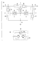
図4の(A)に示すように本実施形態における直流電流遮断装置は、3本の直流送電線11,12,13が電気的に結合する結合点において、直流送電線11,12,13それぞれの線路を互いに、リアクトル22と半導体遮断器23からなる直列回路2で接続する。
図4の(B)に示すように各半導体遮断器23は、2つの半導体スイッチング素子231を互いに逆方向を向くように直列接続して、それと並列にアレスタ232を接続した構成である。
3つの直流送電線11,12,13の結合点において、直列回路2は線路上の点a,b,cをデルタ結線する構成となる。そして、直列回路2のリアクトル22と半導体遮断器23との中点には、それぞれ機械接点式電流断路器32を備えた結線回路3の一端が接続され、それら結線回路3の他端は全て接点jにて互いに接続されている。これはスター結線に相当する。
前記直列回路2の半導体遮断器23の全てが、ここでは図示しない制御回路により定常動作時及びいずれかの送電線での実行発生時に応じてオン/オフ動作が制御される。
また結線回路3の機械接点式電流断路器32も、前記制御回路によりオン/オフ動作が制御される。
また結線回路3の機械接点式電流断路器32も、前記制御回路によりオン/オフ動作が制御される。
次に、本実施形態に係る直流電流遮断装置の電流遮断時の動作を説明する。
定常動作時は、前記制御回路により全ての機械接点式電流断路器32をオンとする一方で、全ての半導体遮断器23はオフとし、電流が機械接点式電流断路器32とリアクトル22を通じて伝送されるものとする。
定常動作時は、前記制御回路により全ての機械接点式電流断路器32をオンとする一方で、全ての半導体遮断器23はオフとし、電流が機械接点式電流断路器32とリアクトル22を通じて伝送されるものとする。
直流送電線で事故が発生すると、事故が発生した直流送電線に向かって事故電流ifが流れる。前記制御回路は事故を検出すると、事故が起きた直流送電線につながる半導体遮断器23をオンにする。すると事故電流ifは、事故が起きた直流送電線につながるリアクトル22と機械接点式電流断路器32から、オンにした半導体遮断器23に転流する。その時、当該機械接点式電流断路器32がゼロ電流となるタイミングが生じるので、その瞬間に前記制御回路により当該機械接点式電流断路器32をオフにする。次に、事故電流が転流した半導体遮断器23をオフにする。これにより、事故が起きた直流送電線は遮断される。
事故が他の系統で発生した場合でも、同様に処理を行なうことで、いずれの直流送電線で事故が起きた場合でも、事故が起きた直流送電線を短時間に切り離すことが可能となる。
以上に述べた如く本実施形態によれば、直流送電線11,12,13それぞれに個別に、図6で示した従来の直流電流遮断装置を接続した場合と比較して、直列回路2の構成規模を半分に削減することができ、ひいては全体の部品点数を低減して、低コスト化と小型化とが可能な直流電流遮断装置を実現できる。
また、半導体遮断器23の半導体スイッチング素子231は、4個以上にして直列に接続しても良い。また電流制御方向を限定するのであれば、各素子が1方向のみを向くように構成しても良い。
またアレスタ232は、個々の半導体スイッチング素子231に対して並列、あるいは複数の半導体スイッチング素子231に対して並列に接続しても良いし、半導体遮断器23自体が複数直列に接続しても良い。
またアレスタ232は、個々の半導体スイッチング素子231に対して並列、あるいは複数の半導体スイッチング素子231に対して並列に接続しても良いし、半導体遮断器23自体が複数直列に接続しても良い。
なお図4では説明しなかったが、同様の構成を4本以上の直流送電線の結合点における直流電流遮断装置にも適用することが可能である。
(第4の実施形態)
図5は、第4の実施形態に係る直流電流遮断装置の構成を示す図である。なお、以下において、図1に示した構成と基本的な考え方は同様であるため、図1に示す直流電流遮断装置の構成要素と同一または相当する構成要素には、図1で使用した符号と同一の符号を付して説明するものとする。
図5は、第4の実施形態に係る直流電流遮断装置の構成を示す図である。なお、以下において、図1に示した構成と基本的な考え方は同様であるため、図1に示す直流電流遮断装置の構成要素と同一または相当する構成要素には、図1で使用した符号と同一の符号を付して説明するものとする。
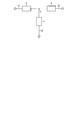
この直流電流遮断装置は、各直列回路2がそれぞれ2つのリアクトル22と2つの半導体遮断器23を交互接続して構成されている。各直列回路2の中点e,f,gには、それぞれ機械接点式電流断路器32の一端が接続され、同機械接点式電流断路器32の他端は全て接点jにて互いに接続されている。
直列回路2の中点e,f,gに接続されていないリアクトル22と半導体遮断器23の接合点には、それぞれ機械接点式電流断路器33の片端が接続され、同機械接点式電流断路器33の他端は隣接する直列回路2のリアクトル22と半導体遮断器23の接合点に接続される。このとき、機械接点式電流断路器33は、同じ直流送電線から2分岐した各直列回路2に属するリアクトル22と半導体遮断器23の接合点同士を接続する。
前記直列回路2の半導体遮断器23の全てが、ここでは図示しない制御回路により定常動作時及びいずれかの送電線での実行発生時に応じてオン/オフ動作が制御される。
また結線回路3の機械接点式電流断路器32,33も、前記制御回路によりオン/オフ動作が制御される。
また結線回路3の機械接点式電流断路器32,33も、前記制御回路によりオン/オフ動作が制御される。
本実施形態に係る直流電流遮断装置の電流遮断時の動作は、前記第3の実施形態と同様であり、いずれの直流送電線で事故が起きた場合でも、事故が起きた直流送電線を切り離すことが可能である
本実施形態によれば、前記第3の実施形態の構成と比較して、機械接点式電流断路器32,33にかかる電圧が低いため、必要な絶縁耐性が低下する。すると、絶縁距離を短くして、開閉速度が遅く安価な機械接点式電流断路器32,33を用いることができるため、さらに低コスト化が可能な直流電流遮断装置を構築することができる。
本実施形態によれば、前記第3の実施形態の構成と比較して、機械接点式電流断路器32,33にかかる電圧が低いため、必要な絶縁耐性が低下する。すると、絶縁距離を短くして、開閉速度が遅く安価な機械接点式電流断路器32,33を用いることができるため、さらに低コスト化が可能な直流電流遮断装置を構築することができる。
また、直列回路2と結線回路3によるブリッジ回路は、さらに多段とすることもできる。その場合の直流電流遮断装置の電流遮断動作も前記第4の実施形態と同様であり、いずれの直流送電線で事故が起きた場合でも、事故が起きた直流送電線を短時間に切り離すことが可能である。
また、こうしたさらなる多段化により、機械接点式電流断路器にかかる電圧がさらに低くできるため、より開閉速度が遅く、より安価な機械接点式電流断路器を用いて、より一層コストの低い直流電流遮断装置を構築することも可能となる。
また、前記直列回路2と結線回路3を、第1の実施形態の構成要素に置き換えても、同様に直流電流遮断装置を構成できる。
例えば、図5に示される直列回路2と結線回路3を、それぞれ、図1に示される直列回路2と結線回路3に置き換えて実施することが可能である。その場合、直列回路2は、例えば4つ以上の機械接点式電流断路器21を直接接続した構成としてもよい。
以上詳述したように、少なくとも1つの実施形態によれば、複数の直流送電線の結合点において、事故電流を高速に遮断可能としながら、部品点数を低減し、低コストで小型化が可能となる。
本発明のいくつかの実施形態を説明したが、これらの実施形態は、例として提示したものであり、発明の範囲を限定することは意図していない。これら実施形態は、その他の様々な形態で実施されることが可能であり、発明の要旨を逸脱しない範囲で、種々の省略、置き換え、変更を行うことができる。これら実施形態やその変形は、発明の範囲や要旨に含まれると同様に、特許請求の範囲に記載された発明とその均等の範囲に含まれる。
Claims (7)
- 直流送電線網の中で3つ以上の直流送電線が電気的に結合される結合点に設置される直流電流遮断装置において、
それぞれが、異なる2つの直流送電線の端部と接続され、2つ以上の電流断路器の直列接続を含む、3つ以上の直列回路と、
各直列回路の中点に一端が接続され、他端が全て1点で互いに接続された、電流を転流する転流回路を含む、3つ以上の結線回路と、
を備えることを特徴とする直流電流遮断装置。 - 定常動作時は、各電流断路器が全てオンとして動作させられ、
前記直流送電線網の系統事故発生時は、事故が発生した直流送電線と他の直流送電線との間に流れる電流が、前記電流断路器、前記結線回路、前記電流断路器の順で流れるように、一部の前記電流断路器がオフに移行させられ、
前記結線回路に含まれる前記転流回路は、事故が発生した直流送電線に流れる電流がゼロとなるように制御され、事故が発生した直流送電線に接続された前記電流断路器は、ゼロ電流の状態でオフに移行させられることを特徴とする請求項1記載の直流電流遮断装置。 - 各直列回路は、前記中点と前記異なる2つの直流送電線の端部との間にそれぞれ、複数の電流断路器の直列接続を含み、
各直流送電線の端部から2分岐する各直列回路における前記複数の電流断路器の結合点同士を接続する転流回路をそれぞれが含む、3つ以上の結線回路をさらに備えることを特徴とする請求項1または2記載の直流電流遮断装置。 - 直流送電線網中で3つ以上の直流送電線が電気的に結合される結合点に設置される直流電流遮断装置において、
それぞれが、異なる2つの直流送電線の端部と接続され、転流手段を含む2つ以上の要素の直列接続を含む、3つ以上の直列回路と、
各直列回路の中点に一端が接続され、他端が全て1点で互いに接続された電流断路器を含む、3つ以上の結線回路と、
を備えることを特徴とする直流電流遮断装置。 - 定常動作時は、各電流断路器が全てオンとして動作させられ、
系統事故発生時は、事故が発生した直流送電線に流れる電流が通る、前記結線回路が備える前記電流断路器の電流がゼロとなるように前記転流手段が動作させられ、ゼロ電流の状態で、事故が発生した直流送電線に流れる電流が通る、前記電流断路器がオフに移行させられることを特徴とする請求項4記載の直流電流遮断装置。 - 各直列回路は、前記中点と前記異なる2つの直流送電線の端部との間にそれぞれ、前記転流手段を含む複数の要素の直列接続を含み、
各直流送電線の端部から2分岐する各直列回路における前記転流手段を含む複数の要素の結合点同士を接続する電流断路器をそれぞれが含む、3つ以上の結線回路をさらに備えることを特徴とする請求項4または5記載の直流電流遮断装置。 - 前記直列回路は、リアクトルと半導体遮断器とを含むことを特徴とする請求項4または5記載の直流電流遮断装置。
Priority Applications (1)
| Application Number | Priority Date | Filing Date | Title |
|---|---|---|---|
| EP16803332.2A EP3306635B1 (en) | 2015-06-02 | 2016-05-31 | Dc current breaker device |
Applications Claiming Priority (2)
| Application Number | Priority Date | Filing Date | Title |
|---|---|---|---|
| JP2015-112055 | 2015-06-02 | ||
| JP2015112055A JP6591204B2 (ja) | 2015-06-02 | 2015-06-02 | 直流電流遮断装置 |
Publications (1)
| Publication Number | Publication Date |
|---|---|
| WO2016194898A1 true WO2016194898A1 (ja) | 2016-12-08 |
Family
ID=57441459
Family Applications (1)
| Application Number | Title | Priority Date | Filing Date |
|---|---|---|---|
| PCT/JP2016/066018 Ceased WO2016194898A1 (ja) | 2015-06-02 | 2016-05-31 | 直流電流遮断装置 |
Country Status (3)
| Country | Link |
|---|---|
| EP (1) | EP3306635B1 (ja) |
| JP (1) | JP6591204B2 (ja) |
| WO (1) | WO2016194898A1 (ja) |
Families Citing this family (8)
| Publication number | Priority date | Publication date | Assignee | Title |
|---|---|---|---|---|
| JP6844352B2 (ja) * | 2017-03-17 | 2021-03-17 | 株式会社明電舎 | 直流遮断装置 |
| WO2019035180A1 (ja) * | 2017-08-15 | 2019-02-21 | 株式会社東芝 | 直流電流遮断装置 |
| JP6456575B1 (ja) * | 2018-04-19 | 2019-01-23 | 三菱電機株式会社 | 直流遮断器 |
| FR3091408B1 (fr) | 2018-12-27 | 2021-01-15 | Inst Supergrid | Dispositif de coupure de courant pour courant continu haute tension avec circuit d’oscillation adaptatif et procédé de pilotage |
| FR3091407B1 (fr) | 2018-12-27 | 2021-10-29 | Inst Supergrid | Dispositif de coupure de courant pour courant continu haute tension avec circuit capacitif tampon et procédé de pilotage |
| FR3094136B1 (fr) * | 2019-03-22 | 2021-04-02 | Inst Supergrid | Dispositif de coupure de courant pour courant continu haute tension avec résonateur et commutation |
| JP7134375B1 (ja) * | 2021-09-27 | 2022-09-09 | 三菱電機株式会社 | 直流遮断器 |
| JP7830672B2 (ja) * | 2022-10-20 | 2026-03-16 | 株式会社東芝 | 直流電流遮断装置 |
Citations (4)
| Publication number | Priority date | Publication date | Assignee | Title |
|---|---|---|---|---|
| JPS5790830A (en) * | 1980-11-26 | 1982-06-05 | Tokyo Shibaura Electric Co | Dc breaker |
| JPS6333537U (ja) * | 1987-04-23 | 1988-03-04 | ||
| WO2014094847A1 (de) * | 2012-12-19 | 2014-06-26 | Siemens Aktiengesellschaft | Vorrichtung zum schalten eines gleichstromes in einem pol eines gleichspannungsnetzes |
| JP2014235834A (ja) * | 2013-05-31 | 2014-12-15 | 株式会社東芝 | 直流電流遮断装置 |
Family Cites Families (3)
| Publication number | Priority date | Publication date | Assignee | Title |
|---|---|---|---|---|
| JPS55121232A (en) * | 1979-03-10 | 1980-09-18 | Tokyo Shibaura Electric Co | Multiterminal system dc breaker |
| ES2585840T3 (es) * | 2012-03-09 | 2016-10-10 | Siemens Aktiengesellschaft | Dispositivo para conmutar una corriente continua en un polo de una red de tensión continua |
| WO2014038008A1 (ja) * | 2012-09-05 | 2014-03-13 | 三菱電機株式会社 | 直流遮断器 |
-
2015
- 2015-06-02 JP JP2015112055A patent/JP6591204B2/ja active Active
-
2016
- 2016-05-31 WO PCT/JP2016/066018 patent/WO2016194898A1/ja not_active Ceased
- 2016-05-31 EP EP16803332.2A patent/EP3306635B1/en active Active
Patent Citations (4)
| Publication number | Priority date | Publication date | Assignee | Title |
|---|---|---|---|---|
| JPS5790830A (en) * | 1980-11-26 | 1982-06-05 | Tokyo Shibaura Electric Co | Dc breaker |
| JPS6333537U (ja) * | 1987-04-23 | 1988-03-04 | ||
| WO2014094847A1 (de) * | 2012-12-19 | 2014-06-26 | Siemens Aktiengesellschaft | Vorrichtung zum schalten eines gleichstromes in einem pol eines gleichspannungsnetzes |
| JP2014235834A (ja) * | 2013-05-31 | 2014-12-15 | 株式会社東芝 | 直流電流遮断装置 |
Non-Patent Citations (1)
| Title |
|---|
| See also references of EP3306635A4 * |
Also Published As
| Publication number | Publication date |
|---|---|
| EP3306635A1 (en) | 2018-04-11 |
| JP6591204B2 (ja) | 2019-10-16 |
| JP2016225198A (ja) | 2016-12-28 |
| EP3306635B1 (en) | 2019-10-30 |
| EP3306635A4 (en) | 2019-01-09 |
Similar Documents
| Publication | Publication Date | Title |
|---|---|---|
| JP6591204B2 (ja) | 直流電流遮断装置 | |
| KR101021776B1 (ko) | 태양광 발전기 | |
| EP2698894B1 (en) | Alternative Power Converter System | |
| JP6109649B2 (ja) | 直流電流遮断装置 | |
| CN105305407B (zh) | 一种光伏高压直流输电系统 | |
| CN204103504U (zh) | 一种基于中高压直流接入的光伏并网发电系统 | |
| WO2016140122A1 (ja) | 直流遮断装置 | |
| CN103248066A (zh) | 基于dc-dc分段器的直流微电网拓扑设计方法 | |
| CN108336750B (zh) | 换流器、基于半vsc三极直流系统及其故障转移控制方法 | |
| CN111478616A (zh) | 一种地铁牵引供电系统及双向变流装置 | |
| CN205646843U (zh) | 用于可再生能源发电的并网逆变器及可再生能源发电系统 | |
| CN107947222A (zh) | 直流风机输电系统 | |
| CN110463006A (zh) | 具有多个风能设施的风电场 | |
| JP6462430B2 (ja) | 直流電流遮断装置 | |
| CN106877690A (zh) | 用于连接多条交流线路的多端口换流装置 | |
| JP2017004869A (ja) | 直流電流遮断装置 | |
| CN111712982B (zh) | 故障处理 | |
| CN109347134B (zh) | 双极柔性直流电网极线电气主接线系统及在线检修方法 | |
| RU2698469C1 (ru) | Подходящее для двухцепных линий устройство продольной компенсации | |
| CN103236794A (zh) | 直流dc-dc分段器 | |
| US20200287378A1 (en) | Array of electrical generator units | |
| CN115133568A (zh) | 用于功率转换组合件的寄生电感控制的有源中性点箝位开关序列 | |
| US20230170814A1 (en) | Solid-state transformer and power supply system | |
| Larruskain et al. | Requirements for fault protection in HVDC grids | |
| JP6377544B2 (ja) | 直流電流遮断装置 |
Legal Events
| Date | Code | Title | Description |
|---|---|---|---|
| 121 | Ep: the epo has been informed by wipo that ep was designated in this application |
Ref document number: 16803332 Country of ref document: EP Kind code of ref document: A1 |
|
| NENP | Non-entry into the national phase |
Ref country code: DE |
|
| WWE | Wipo information: entry into national phase |
Ref document number: 2016803332 Country of ref document: EP |