WO2016199203A1 - モータ及び圧縮機 - Google Patents
モータ及び圧縮機 Download PDFInfo
- Publication number
- WO2016199203A1 WO2016199203A1 PCT/JP2015/066515 JP2015066515W WO2016199203A1 WO 2016199203 A1 WO2016199203 A1 WO 2016199203A1 JP 2015066515 W JP2015066515 W JP 2015066515W WO 2016199203 A1 WO2016199203 A1 WO 2016199203A1
- Authority
- WO
- WIPO (PCT)
- Prior art keywords
- iron core
- insulator
- core
- axial direction
- motor
- Prior art date
- Legal status (The legal status is an assumption and is not a legal conclusion. Google has not performed a legal analysis and makes no representation as to the accuracy of the status listed.)
- Ceased
Links
Images


Classifications
-
- H—ELECTRICITY
- H02—GENERATION; CONVERSION OR DISTRIBUTION OF ELECTRIC POWER
- H02K—DYNAMO-ELECTRIC MACHINES
- H02K3/00—Details of windings
- H02K3/32—Windings characterised by the shape, form or construction of the insulation
- H02K3/325—Windings characterised by the shape, form or construction of the insulation for windings on salient poles, such as claw-shaped poles
-
- H—ELECTRICITY
- H02—GENERATION; CONVERSION OR DISTRIBUTION OF ELECTRIC POWER
- H02K—DYNAMO-ELECTRIC MACHINES
- H02K1/00—Details of the magnetic circuit
- H02K1/06—Details of the magnetic circuit characterised by the shape, form or construction
- H02K1/12—Stationary parts of the magnetic circuit
- H02K1/14—Stator cores with salient poles
- H02K1/146—Stator cores with salient poles consisting of a generally annular yoke with salient poles
- H02K1/148—Sectional cores
-
- H—ELECTRICITY
- H02—GENERATION; CONVERSION OR DISTRIBUTION OF ELECTRIC POWER
- H02K—DYNAMO-ELECTRIC MACHINES
- H02K1/00—Details of the magnetic circuit
- H02K1/06—Details of the magnetic circuit characterised by the shape, form or construction
- H02K1/12—Stationary parts of the magnetic circuit
- H02K1/18—Means for mounting or fastening magnetic stationary parts on to, or to, the stator structures
- H02K1/185—Means for mounting or fastening magnetic stationary parts on to, or to, the stator structures to outer stators
-
- H—ELECTRICITY
- H02—GENERATION; CONVERSION OR DISTRIBUTION OF ELECTRIC POWER
- H02K—DYNAMO-ELECTRIC MACHINES
- H02K3/00—Details of windings
- H02K3/32—Windings characterised by the shape, form or construction of the insulation
- H02K3/34—Windings characterised by the shape, form or construction of the insulation between conductors or between conductor and core, e.g. slot insulation
- H02K3/345—Windings characterised by the shape, form or construction of the insulation between conductors or between conductor and core, e.g. slot insulation between conductor and core, e.g. slot insulation
-
- H—ELECTRICITY
- H02—GENERATION; CONVERSION OR DISTRIBUTION OF ELECTRIC POWER
- H02K—DYNAMO-ELECTRIC MACHINES
- H02K3/00—Details of windings
- H02K3/32—Windings characterised by the shape, form or construction of the insulation
- H02K3/38—Windings characterised by the shape, form or construction of the insulation around winding heads, equalising connectors, or connections thereto
-
- H—ELECTRICITY
- H02—GENERATION; CONVERSION OR DISTRIBUTION OF ELECTRIC POWER
- H02K—DYNAMO-ELECTRIC MACHINES
- H02K3/00—Details of windings
- H02K3/46—Fastening of windings on the stator or rotor structure
- H02K3/52—Fastening salient pole windings or connections thereto
- H02K3/521—Fastening salient pole windings or connections thereto applicable to stators only
- H02K3/522—Fastening salient pole windings or connections thereto applicable to stators only for generally annular cores with salient poles
-
- H—ELECTRICITY
- H02—GENERATION; CONVERSION OR DISTRIBUTION OF ELECTRIC POWER
- H02K—DYNAMO-ELECTRIC MACHINES
- H02K15/00—Processes or apparatus specially adapted for manufacturing, assembling, maintaining or repairing of dynamo-electric machines
- H02K15/10—Applying solid insulation to windings, stators or rotors, e.g. applying insulating tapes
-
- H—ELECTRICITY
- H02—GENERATION; CONVERSION OR DISTRIBUTION OF ELECTRIC POWER
- H02K—DYNAMO-ELECTRIC MACHINES
- H02K2203/00—Specific aspects not provided for in the other groups of this subclass relating to the windings
- H02K2203/06—Machines characterised by the wiring leads, i.e. conducting wires for connecting the winding terminations
-
- H—ELECTRICITY
- H02—GENERATION; CONVERSION OR DISTRIBUTION OF ELECTRIC POWER
- H02K—DYNAMO-ELECTRIC MACHINES
- H02K3/00—Details of windings
- H02K3/32—Windings characterised by the shape, form or construction of the insulation
-
- H—ELECTRICITY
- H02—GENERATION; CONVERSION OR DISTRIBUTION OF ELECTRIC POWER
- H02K—DYNAMO-ELECTRIC MACHINES
- H02K3/00—Details of windings
- H02K3/32—Windings characterised by the shape, form or construction of the insulation
- H02K3/34—Windings characterised by the shape, form or construction of the insulation between conductors or between conductor and core, e.g. slot insulation
-
- H—ELECTRICITY
- H02—GENERATION; CONVERSION OR DISTRIBUTION OF ELECTRIC POWER
- H02K—DYNAMO-ELECTRIC MACHINES
- H02K5/00—Casings; Enclosures; Supports
- H02K5/04—Casings or enclosures characterised by the shape, form or construction thereof
- H02K5/08—Insulating casings
Definitions
- the present invention relates to a motor including an iron core and an insulator constituting a stator, and a compressor including the motor.
- a stator of a motor a stator having a plurality of core cores arranged in an annular shape, a winding coil wound around each core core, and an insulator that insulates the core core from the winding coil is known.
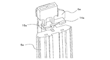
- an insulator protrusion 14a is provided on the lower end surface of the insulator
- an insulator connecting hole 15a is provided on the upper end surface of the iron core 5a.
- wears with the insulator 6a to the iron core 5a as shown in FIG. 11 by fitting this insulator protrusion part 14a and the insulator connection hole 15a is proposed (for example, refer patent document 1). .
- a mounting portion extending in the axial direction of the iron core is formed on the insulator. And the thing which pinches
- a protrusion is provided on the surface facing the upper end surface of the iron core of the insulator, and a hole into which the insulator is inserted is provided on the upper end surface of the iron core.
- the mounting portion provided on the insulator sandwiches both ends of the iron core in the circumferential direction, so that the winding space of the iron core is reduced. There was a problem that caused a decrease in efficiency.
- the present invention has been made to solve the above-described problems, and an object of the present invention is to obtain a motor and a compressor that do not reduce the winding space without disturbing the flow of magnetic force.
- a motor according to the present invention includes an iron core and an insulator disposed on an end surface in the axial direction of the iron core, and the iron core has at least one groove portion on an outer peripheral portion, and the groove portion includes: The insulator is provided in the axial direction of the outer peripheral portion from the end surface of the iron core, and the insulator has at least one first protrusion protruding downward in the axial direction from the contact surface with the iron core, and the first The projecting portion is fitted with the groove portion.
- the iron core is provided with at least one groove portion in the axial direction from the end surface to the outer diameter side surface
- the insulator is at least one first protrusion that protrudes downward in the axial direction from the contact surface with the iron core.
- the first protrusion is configured to fit with the groove.
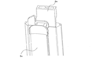
- FIG. 1 is a schematic diagram of a compressor equipped with a motor according to Embodiment 1 of the present invention.
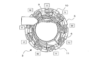
- FIG. 2A is a schematic top view of the stator of the motor according to Embodiment 1 of the present invention.
- FIG. 2B is a schematic side view of the stator of the motor according to Embodiment 1 of the present invention. As shown in FIGS.
- the compressor 100 includes a sealed container 1, a suction pipe 1g for supplying a refrigerant into the sealed container 1, a reservoir container 1h connected to the suction pipe 1g, A compression mechanism 1d for compressing refrigerant, a rotating shaft 1c, a rotor 3 connected to the shaft 1c, a stator 2 for rotating the rotor 3, and a refrigerant compressed from the sealed container 1 are connected to the suction pipe 1g.
- a discharge pipe 1f for discharging.
- the shaft 1c, the stator 2, and the rotor 3 constitute a motor 1b.
- the hermetic container 1 constitutes an outer shell of the compressor 100.
- the sealed container 1 at least a compression mechanism 1d, a motor 1b, and the like are provided.
- the hermetic container 1 is composed of an upper shell 1a1 and a lower shell 1a2 that constitutes a shell and a lower shell of the compressor 100.
- the upper shell 1a1 is an end side shell that constitutes the upper part of the hermetic container 1, and is subjected to, for example, drawing and has a shape close to a hemisphere.
- the upper shell 1a1 is connected to a discharge pipe 1f provided in communication with the inside and outside of the sealed container 1.
- the lower shell 1a2 constitutes an intermediate portion and a lower portion of the sealed container 1, and has, for example, a bottomed cylindrical shape whose lower side is closed. That is, the lower shell 1a2 is formed with an opening on the upper side to press-fit the upper shell 1a1, and stores the refrigerating machine oil used for reducing the sliding friction of the compression mechanism 1d by closing the lower side. It is like that.
- the lower shell 1 a 2 is connected to a suction pipe 1 g for supplying a refrigerant into the sealed container 1.
- the stator 2 of the motor 1b is attached to the inner peripheral surface of the lower shell 1a2, and the compression mechanism 1d is attached to the lower side of the inner peripheral surface of the lower shell 1a2 to which the stator 2 is attached. Yes.
- suction pipe 1g and reservoir 1h One of the suction pipes 1g is connected to the lower shell 1a2 of the sealed container 1 so as to communicate with the cylinder of the compression mechanism 1d.
- the other end of the suction pipe 1g is connected to a liquid reservoir 1h.
- the liquid reservoir 1h has a function as a muffler for reducing refrigerant sound and the like flowing into the compressor 100.
- the liquid reservoir 1h also has a function as an accumulator capable of storing a liquid refrigerant.
- One side of the liquid reservoir 1h is connected to the suction pipe 1g.
- the compression mechanism 1 d compresses the refrigerant supplied via the liquid reservoir 1 h and the suction pipe 1 g and discharges it into the sealed container 1.
- the compression mechanism 1d is attached to the inner surface of the lower shell 1a2.
- the compression mechanism 1d is provided with a cylinder that compresses the refrigerant supplied from the suction pipe 1g, a piston that slidably rotates the cylinder, and the like. This piston is connected to the shaft 1c and moves eccentrically in the cylinder.
- the compression mechanism 1d is provided with bearings 1e that rotatably support the shaft 1c on the upper end surface side and the lower end surface side.
- the motor 1b has a shaft 1c whose lower end is connected to the bearing 1e of the compression mechanism 1d, a rotor 3 to which the shaft 1c is fixed and transmits its rotation to the shaft 1c, and a multi-layer winding coil 11 (see FIG. 2B). Is wound around the stator 2.
- the rotor 3 is fixed to the upper side of the connection position of the compression mechanism 1d, and the shaft 1c rotates with the rotation of the rotor 3 to rotate the piston of the compression mechanism 1d.
- the rotor 3 is provided with a permanent magnet (not shown) and is rotatably supported by the shaft 1c.
- the rotor 3 is supported at a predetermined interval with respect to the inside of the stator 2.
- the stator 2 rotates the rotor 3 and has an outer peripheral surface fixed to the inner peripheral surface of the lower shell 1a2.
- the stator 2 includes a core core 5 composed of a plurality of electromagnetic steel plates, an insulator 6 attached to the core core 5, and a plurality of layers on the core core 5 via the insulator 6. It has a winding coil 11 to be wound.
- the iron core 5 is obtained by laminating a plurality of electromagnetic steel plates, and a plurality of cores 5 are arranged in an annular shape.
- An insulator 6 used for insulation between the winding coil 11 and the iron core 5 is attached to the iron core 5.
- the insulator 6 is made of, for example, a resin so that the winding coil 11 and the iron core 5 are insulated.
- the insulator 6 on the compression mechanism 1d side of the insulator 6 is an insulator L side 6B
- the insulator 6 on the upper shell 1a1 side of the insulator 6 is an insulator U side 6A. That is, a portion of the insulator 6 located on the lower side of the lower end surface from the iron core 5 is referred to as an insulator L side 6B, and a portion of the insulator 6 located on the upper side of the upper end surface from the iron core 5 is referred to as an insulator U side 6A.
- the insulator L side 6 ⁇ / b> B can see a part of the winding coil 11 wound around the insulator L side 6 ⁇ / b> B.
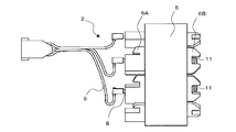
- a cavity (not shown) is formed on the insulator U side 6A, and a magmate 8 to which a lead wire 9 used for supplying electricity to the U phase, V phase and W phase is connected is embedded. ing. Further, the U phase, the V phase, and the W phase are electrically connected to each other via the jumper wire 10.
- the winding coil 11 is wound around the iron core 5 through a plurality of layers via the insulator U side 6A and the insulator L side 6B.
- the stator 2 functions as an electromagnet, and interacts with a permanent magnet provided on the rotor 3 to generate a rotational force of the rotor 3.
- the discharge pipe 1f is a pipe that discharges the high-temperature and high-pressure refrigerant in the sealed container 1 compressed by the compression mechanism 1d to the outside.
- One end of the discharge pipe 1f is connected to a four-way valve (not shown) used for switching the flow path, and the other end is connected to the upper shell 1a1 so as to communicate with the inside and outside of the sealed container 1. .
- FIG. 3A is a schematic bottom view of a single iron core core of the motor according to Embodiment 1 of the present invention.
- FIG. 3B is a schematic side view of a single iron core core of the motor according to Embodiment 1 of the present invention.
- FIG. 3C is a schematic top view of a single iron core core of the motor according to Embodiment 1 of the present invention.
- the iron core 5 has a short-side L-side winding portion 12 a around which the coil is wound below the iron core 5, and a long-side side winding around which the coil is wound on the side surface of the iron core 5.
- the short side U side winding part 12c which winds a coil above the part 12b and the iron core 5 is provided.
- a winding coil 11 is wound around the short side L-side winding portion 12a in parallel with the short side L-side winding portion 12a, and a winding coil 11 is wound around the long side surface winding portion 12b. It is wound parallel to the winding part 12b.
- the winding coil 11 is wound around the short side U-side winding portion 12c with an inclination so that the winding is shifted by one pitch. In this way, the winding coil 11 is wound around the iron core 5 in a plurality of layers.
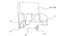
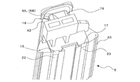
- FIG. 4 is an enlarged perspective view of the insulator of the motor according to Embodiment 1 of the present invention.
- the insulator U-side 6 ⁇ / b> A has a lower surface in contact with the iron core 5 as an insulator-side iron core contact surface 20.
- Flat claws 16 and claws 17 protrude downward in the axial direction on both ends of the outer edge of the insulator-side iron core contact surface 20 (the outer peripheral side of the iron core 5).
- a claw 18 and a claw 19 protrude downward in the axial direction on both ends of the inner edge of the insulator-side iron core contact surface 20 (inner diameter side of the iron core 5).
- the lower surface side of the insulator L side 6B has the same configuration as that of the insulator U side 6A.
- the insulator L side 6 ⁇ / b> B has the lower surface in contact with the iron core 5 as the insulator side iron core contact surface 20.
- Flat claws 16 and claws 17 protrude downward in the axial direction on both end sides of the outer edge (iron core 5 side) of the insulator-side iron core contact surface 20.
- a claw 18 and a claw 19 protrude downward in the axial direction on both end sides of the inner edge of the insulator-side iron core contact surface 20 (inner diameter side of the iron core 5).
- claw 17 are corresponded to the "1st projection part" in this invention.
- the claw 17 and the claw 18 correspond to the “second protrusion” in the present invention.
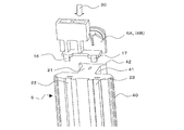
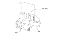
- FIG. 5 is an enlarged perspective view showing a method for attaching the insulator and the iron core of the motor according to Embodiment 1 of the present invention.
- the iron core 5 is positioned at the core back portion 40 extending in the circumferential direction, the tooth portion 41 protruding from the center portion of the core back portion 40 in the center direction, and the tip of the tooth portion 41. Teeth tip portion 42 to be configured.
- An end surface in the axial direction in which the iron core 5 contacts the insulator is referred to as an iron core-side insulator contact surface 21.
- the core back part 40 is provided with the groove part 22 and the groove part 23 on the outer peripheral part, and the groove parts 22 and 23 are provided in the axial direction of the outer peripheral part from the iron core side insulator contact surface 21.
- the groove part 22 and the groove part 23 are provided in the outer peripheral part of the core back part 40 in the site
- the insulator U side 6A and the insulator L side 6B are attached to the iron core 5 from above the iron core 5 as indicated by the direction of the arrow 30. At this time, the insulator side iron core contact surface 20 and the iron core side insulator contact surface 21 are bonded.
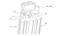
- FIG. 6 is an enlarged perspective view showing a state where an insulator is attached to the iron core of the motor according to Embodiment 1 of the present invention.
- the claw 16 is fitted into the groove portion 22, and the claw 17 is fitted into the groove portion 23, and is attached by an interference fit or an intermediate fit.
- the claw 18 and the claw 19 on the insulator U side 6 ⁇ / b> A come into contact with the inner peripheral surface of the tooth distal end portion 42.
- the insulator U side 6A is attached to the iron core 5 such that the claws 16, 17, 18, and 19 sandwich the iron core 5.
- the insulator L side 6B is also attached to the iron core 5 in the same manner as the insulator U side 6A. That is, the insulator U side 6A is provided on one end face of the iron core 5, and the insulator L side 6B is provided on the other end face.
- the claw 18 and the claw 19 abut on the inner peripheral surface of the tooth tip portion 42 that does not overlap the projection surface of the tooth portion 41 on the tooth tip portion 42 of the tooth tip portion 42.
- the motor 1 b includes the rotor 3 on the inner peripheral side of the iron core 5 arranged in an annular shape, but the claw 18 and the claw 19 are provided at positions that do not contact the rotor 3.
- the claw 16 fits in the groove portion 22 so as not to protrude from the outer peripheral surface of the iron core 5.
- the claw 17 fits in the groove 23 so as not to protrude from the outer peripheral surface of the iron core 5.
- claw 17 was made into flat form, this invention is not limited to this, You may form in circular arc shape or rod shape.
- the insulator 6 provided the nail
- the present invention is not limited to this, and when the length of the claw is long and the width of the claw is wide, the insulator 6 can be stably attached to the iron core 5, so that the claw is attached to the insulator 6 and the inner diameter of the iron core 5.
- One each may be provided on the side and the outer diameter side.
- three or more claws of the insulator 6 may be provided on the insulator 6 on the inner diameter side and the outer diameter side of the iron core 5.
- the motor 1b includes the iron core 5 and the insulator 6 arranged on the end surface in the axial direction of the iron core 5, and the iron core 5 is disposed on the outer peripheral portion.
- At least one groove portion 22, 23 is provided, the groove portion 22, 23 is provided in the axial direction from the end surface to the outer peripheral surface, and the insulator 6 protrudes downward from the contact surface with the iron core 5 in the axial direction.
- the claws 16 and 17 are provided, and the claws 16 and 17 are fitted with the groove portions 22 and 23.
- the iron core 5 is comprised from the core back part 40 extended in the circumferential direction, the teeth part 41 protruded in the center direction from the center part of the core back, and the teeth front-end
- the insulator 6 includes at least one claw 18, 19 that protrudes downward in the axial direction from the contact surface with the iron core 5, and the claw 18, 19 abuts against the inner peripheral surface of the tooth tip portion 42. Sandwiches the iron core 5. By doing in this way, the effect that an insulator is stably installed to iron core 5 can be acquired.
- the claw 18 and the claw 19 abut on the inner peripheral surface of the tooth tip portion 42 that does not overlap the projection surface of the tooth portion 41 on the tooth tip portion 42 of the tooth tip portion 42.
- the iron core 5 is comprised from the core back part 40 extended in the circumferential direction, the teeth part 41 protruded in the center direction from the center part of the core back, and the teeth front-end
- the groove portions 22 and 23 are provided in a portion of the outer peripheral portion of the core back portion 40 that does not overlap with the projection surface of the teeth portion 41 onto the core back portion 40.
- the rotor 3 is provided rotatably on the inner peripheral side of the iron core 5, and the claw 18 and the claw 19 are provided at positions where they do not come into contact with the rotor 3.
- Embodiment 2 Since the basic configuration of the motor 1b in the second embodiment is the same as that of the motor 1b in the first embodiment, the second embodiment will be described below with a focus on differences from the first embodiment.
- the difference between the first embodiment and the second embodiment is that the insulator is fixed to the iron core with two claws provided on the insulator.
- FIG. 7 is an enlarged perspective view showing a method of attaching the insulator and the iron core of the motor according to Embodiment 2 of the present invention.
- a claw 24 and a claw 25 protrude downward in the axial direction on both end sides of the outer edge (the outer peripheral side of the iron core 5) of the lower surface of the insulator U side 6 ⁇ / b> A.
- the claw 24 and the claw 25 have a trapezoidal shape in cross section.
- the insulator L side 6B has the same configuration as the insulator U side 6A.
- the core back part 40 of the iron core 5 is provided with the groove part 26 and the groove part 27 on the outer peripheral part, and the groove parts 26 and 27 are provided in the axial direction of the outer peripheral part from the iron core side insulator contact surface 21.
- the groove 26 and the groove 27 are trapezoidal in cross section.
- the groove part 26 and the groove part 27 are provided in the outer peripheral part of the core back part 40 in the site
- the trapezoidal claw 24 on the insulator U side 6A is fitted in the trapezoidal groove portion 26, and the trapezoidal claw 25 is fitted in the trapezoidal groove portion 27, whereby the circumferential direction of the iron core 5 on the insulator U side 6A. And the radial position is determined.
- the fixing of the insulator U side 6A to the iron core 5 in the axial direction is fixed by an interference fit or an intermediate fit.
- the insulator L side 6B is also attached to the iron core 5 in the same manner as the insulator U side 6A. That is, the insulator U side 6A is provided on one end face of the iron core 5, and the insulator L side 6B is provided on the other end face.
- the claw 24 does not protrude from the groove portion 26 in the outer diameter direction.
- the claw 25 does not protrude from the groove portion 27 in the outer diameter direction.
- the claws 24 and 25 and the groove portions 26 and 27 have a trapezoidal configuration in the cross section.
- an insulator can be stably fixed to an iron core.
- an effect of reducing the number of parts can be obtained.
- Embodiment 3 Since the basic configuration of the motor 1b in the third embodiment is the same as that of the motor 1b in the first embodiment, the second embodiment will be described below with a focus on differences from the first embodiment.
- the difference between the first embodiment and the second embodiment is that a hole is provided in the insulator and a protrusion is provided in the iron core.
- FIG. 8 is an enlarged perspective view of the insulator of the motor according to Embodiment 3 of the present invention.
- a protrusion insertion hole 28 is provided in the insulator side iron core contact surface 20 of the insulator U side 6 ⁇ / b> A.
- the insulator L side 6B is provided with a protrusion insertion hole 28 in the insulator side iron core contact surface 20.
- FIG. 9 is an enlarged perspective view showing a method for attaching the insulator and the iron core of the motor according to the third embodiment of the present invention.
- the core-core-side insulator contact surface 21 of the iron core 5 is provided with a convex portion 29 protruding in the axial direction.
- the insulator U side 6 ⁇ / b> A is fixed to the iron core 5 by fitting the protruding portion insertion hole 28 and the convex portion 29.
- the insulator L side 6 ⁇ / b> B is also fixed to the iron core 5.
- the motor 1b includes the iron core 5 and the insulator 6 disposed on the end surface in the axial direction of the iron core 5, and the iron core 5 has an upper end surface or a lower surface.
- a protrusion 29 protruding in the axial direction is provided on at least one of the end faces, and the insulator 6 is provided with a protrusion insertion hole 28 at the lower end face, and the protrusion 29 is configured to fit into the protrusion insertion hole 28.
Landscapes
- Engineering & Computer Science (AREA)
- Power Engineering (AREA)
- Insulation, Fastening Of Motor, Generator Windings (AREA)
- Iron Core Of Rotating Electric Machines (AREA)
- Compressor (AREA)
Abstract
Description
[圧縮機の構成]
図1は、本発明の実施の形態1に係るモータを搭載する圧縮機の概略図である。図2Aは、本発明の実施の形態1に係るモータのステータの上面概略図である。図2Bは、本発明の実施の形態1に係るモータのステータの側面概略図である。図1~図2Bに示されるように、圧縮機100は、密閉容器1と、密閉容器1内に冷媒を供給するための吸入パイプ1gと、吸入パイプ1gに接続される液だめ容器1hと、吸入パイプ1gに接続され、冷媒を圧縮する圧縮機構1dと、回転するシャフト1cと、シャフト1cに接続されるローター3と、ローター3を回転させるステータ2と、密閉容器1から圧縮された冷媒を吐出する吐出パイプ1fとを有している。なお、シャフト1cと、ステータ2と、ローター3とでモータ1bが構成される。
密閉容器1は、圧縮機100の外郭を構成するものである。密閉容器1内には、圧縮機構1d及びモータ1bなどが少なくとも設けられている。密閉容器1は、上シェル1a1と、圧縮機100の胴体部及び下部の外郭を構成する下シェル1a2とから構成されている。
吸入パイプ1gの一方は、圧縮機構1dのシリンダと連通するように、密閉容器1の下シェル1a2に接続されているものである。吸入パイプ1gの他方は、液だめ容器1hに接続されている。液だめ容器1hは、圧縮機100に流入する冷媒音などを低減するマフラーとしての機能を有するものである。また、液だめ容器1hは、液冷媒を貯留することができるアキュムレータとしての機能も有している。この液だめ容器1hは、一方が吸入パイプ1gに接続されている。
圧縮機構1dは、液だめ容器1h及び吸入パイプ1gを介して供給される冷媒を圧縮し、密閉容器1の内部に放出するものである。圧縮機構1dは、下シェル1a2の内側面に取り付けられている。圧縮機構1dには、吸入パイプ1gから供給される冷媒を圧縮するシリンダ、及び当該シリンダを摺動自在に回転するピストンなどが設けられている。このピストンは、シャフト1cに接続され、シリンダ内を偏心運動する。圧縮機構1dには、上端面側及び下端面側にシャフト1cを回転自在に支持する軸受1eが設けられている。
モータ1bは、下端側が圧縮機構1dの軸受1eに接続されるシャフト1cと、シャフト1cが固定され自身の回転をシャフト1cに伝達するローター3と、複数層の巻線コイル11(図2B参照)が巻き付けられているステータ2とを有している。シャフト1cは、圧縮機構1dの接続位置の上側にローター3が固定され、ローター3の回転とともに自身が回転し、圧縮機構1dのピストンを回転させるものである。ローター3は、永久磁石(図示省略)が設けられ、シャフト1cによって回転自在に支持されているものである。ローター3は、ステータ2の内側に対して、予め設定された間隔を空けて支持されている。ステータ2は、ローター3を回転させるものであり、外周面が下シェル1a2の内周面に固定されて設けられている。
吐出パイプ1fは、圧縮機構1dで圧縮された密閉容器1内の高温高圧冷媒を外に吐出する配管である。この吐出パイプ1fは、一方が流路の切り替えなどを行うのに利用される図示省略の四方弁などに接続され、他方が密閉容器1の内外を連通するように上シェル1a1に接続されている。
なお、爪16及び爪17は本発明における「第一の突起部」に相当する。また、爪17及び爪18は本発明における「第二の突起部」に相当する。
以上のことから、本実施の形態1によれば、モータ1bが、鉄心コア5と、鉄心コア5の軸線方向の端面に配置されるインシュレータ6と、を備え、鉄心コア5は、外周部に少なくとも1つの溝部22、23を設け、当該溝部22、23は、端面から外周面の軸線方向に設けられ、インシュレータ6は、鉄心コア5との接触面から軸線方向の下方に突出する少なくとも1つの爪16、17を設け、爪16、17は、溝部22、23と嵌合するようにする。このようにすることで、鉄心コアの軸線方向の端面にインシュレータ取付用の穴を設ける必要がなくなるため、磁力の流れを妨げずに巻線スペースを減少させないようにしたモータを得ることができる。
本実施の形態2におけるモータ1bの基本的な構成は実施の形態1におけるモータ1bと同様であるため、以下、実施の形態1との相違点を中心に本実施の形態2を説明する。実施の形態1と本実施の形態2との相違点は、インシュレータに設けられた2つの爪でインシュレータを鉄心コアに固定する点である。
以上のことから、本実施の形態2によれば、爪24、25及び溝部26、27は、横断面において台形の構成とする。このようにすることで、実施の形態1の効果に加えて、インシュレータを鉄心コアに安定して固定することができる。また、インシュレータの内縁側に爪を設ける必要がなくなるため、部品数の削減という効果を得ることもできる。
本実施の形態3におけるモータ1bの基本的な構成は実施の形態1におけるモータ1bと同様であるため、以下、実施の形態1との相違点を中心に本実施の形態2を説明する。実施の形態1と本実施の形態2との相違点は、インシュレータに穴部を設け、鉄心コアに突起部を設ける点である。
以上のことから、本実施の形態1によれば、モータ1bが、鉄心コア5と、鉄心コア5の軸線方向の端面に配置されるインシュレータ6と、備え、鉄心コア5は、上端面又は下端面の少なくとも一方に軸線方向に突出する凸部29を設け、インシュレータ6は、下端面に突起部差し込み穴28を設け、凸部29は、突起部差し込み穴28と嵌合する構成とする。このようにすることで、鉄心コアの軸線方向の端面にインシュレータ取付用の穴を設ける必要がなくなるため、磁力の流れを妨げずにモータの効率低下を引き起こさないモータを得ることができる。
Claims (11)
- 鉄心コアと、
前記鉄心コアの軸線方向の端面に配置されるインシュレータと、を備え、
前記鉄心コアは、外周部に少なくとも1つの溝部を有し、
当該溝部は、前記鉄心コアの前記端面から外周部の軸線方向に設けられ、
前記インシュレータは、前記鉄心コアとの接触面から軸線方向の下方に突出する少なくとも1つの第一の突起部を有し、
前記第一の突起部は、前記溝部と嵌合する
モータ。 - 前記鉄心コアは、周方向に延在するコアバック部、該コアバック部の中央部から中心方向に突出したティース部、及び該ティース部の先端に位置するティース先端部とから構成され、
前記インシュレータは、前記鉄心コアとの接触面から軸線方向の下方に突出する少なくとも1つの第二の突起部を有し、
前記第二の突起部は、前記ティース先端部の内周面と当接し、前記インシュレータが前記鉄心コアを挟持する
請求項1に記載のモータ。 - 前記第二の突起部は、前記ティース先端部のうち、前記ティース部の前記ティース先端部への投影面と重複しない前記ティース先端部の内周面と当接する
請求項2に記載のモータ。 - 前記鉄心コアの内周側に回転自在に配置されたローターを備え、
前記第二の突起部は、前記ローターと接触しない位置に設けられている
請求項2又は3に記載のモータ。 - 前記第一の突起部及び前記溝部は、横断面において台形である
請求項1に記載のモータ。 - 前記鉄心コアは、周方向に延在するコアバック部、該コアバック部の中央部から中心方向に突出したティース部、及び該ティース部の先端に位置するティース先端部とから構成され、
前記溝部は、前記コアバック部の外周部のうち、前記ティース部の前記コアバック部への投影面と重複しない部位に設けられている
請求項1又は5に記載のモータ。 - 前記第一の突起部は、前記鉄心コアの外周面から突出しないように前記溝部に収まる
請求項1~6のいずれかに記載のモータ。 - 前記第一の突起部は、前記溝部に対して、しまりばめ、又は、中間ばめにより固定される
請求項1~7のいずれかに記載のモータ。 - 前記インシュレータは、前記鉄心コアの軸線方向の両端面にそれぞれ設けられている
請求項1~8のいずれかに記載のモータ。 - 鉄心コアと、
前記鉄心コアの軸線方向の端面に配置されるインシュレータと、備え、
前記鉄心コアは、上端面又は下端面の少なくとも一方に軸線方向に突出する凸部を設け、
前記インシュレータは、下端面に穴を設け、
前記凸部は、前記穴と嵌合する
モータ。 - 請求項1~10のいずれか一項に記載のモータを備えた
圧縮機。
Priority Applications (6)
| Application Number | Priority Date | Filing Date | Title |
|---|---|---|---|
| JP2017522774A JP6479179B2 (ja) | 2015-06-08 | 2015-06-08 | モータ及び圧縮機 |
| US15/554,730 US10797551B2 (en) | 2015-06-08 | 2015-06-08 | Motor and compressor having insulator and stator core with non-overlapping grooves |
| PCT/JP2015/066515 WO2016199203A1 (ja) | 2015-06-08 | 2015-06-08 | モータ及び圧縮機 |
| EP15864315.5A EP3128649B1 (en) | 2015-06-08 | 2015-06-08 | Motor and compressor |
| CN201610304898.0A CN106253533B (zh) | 2015-06-08 | 2016-05-10 | 马达以及压缩机 |
| CN201620419096.XU CN205725224U (zh) | 2015-06-08 | 2016-05-10 | 马达以及压缩机 |
Applications Claiming Priority (1)
| Application Number | Priority Date | Filing Date | Title |
|---|---|---|---|
| PCT/JP2015/066515 WO2016199203A1 (ja) | 2015-06-08 | 2015-06-08 | モータ及び圧縮機 |
Publications (1)
| Publication Number | Publication Date |
|---|---|
| WO2016199203A1 true WO2016199203A1 (ja) | 2016-12-15 |
Family
ID=57304197
Family Applications (1)
| Application Number | Title | Priority Date | Filing Date |
|---|---|---|---|
| PCT/JP2015/066515 Ceased WO2016199203A1 (ja) | 2015-06-08 | 2015-06-08 | モータ及び圧縮機 |
Country Status (5)
| Country | Link |
|---|---|
| US (1) | US10797551B2 (ja) |
| EP (1) | EP3128649B1 (ja) |
| JP (1) | JP6479179B2 (ja) |
| CN (2) | CN106253533B (ja) |
| WO (1) | WO2016199203A1 (ja) |
Cited By (2)
| Publication number | Priority date | Publication date | Assignee | Title |
|---|---|---|---|---|
| JP2018196171A (ja) * | 2017-05-12 | 2018-12-06 | 株式会社デンソー | 電機子及びモータ |
| WO2019073921A1 (ja) * | 2017-10-12 | 2019-04-18 | ダイキン工業株式会社 | ステータ、モータおよび圧縮機 |
Families Citing this family (4)
| Publication number | Priority date | Publication date | Assignee | Title |
|---|---|---|---|---|
| EP3128649B1 (en) * | 2015-06-08 | 2021-07-28 | Mitsubishi Electric Corporation | Motor and compressor |
| JP2019054671A (ja) * | 2017-09-15 | 2019-04-04 | 日本電産株式会社 | モータ、送風装置及び掃除機 |
| JP7030140B2 (ja) * | 2018-02-01 | 2022-03-04 | 日立Astemo株式会社 | 回転電機、固定子 |
| CN110912295A (zh) * | 2019-11-07 | 2020-03-24 | 联创汽车电子有限公司 | 定子单体和电机定子单元 |
Citations (6)
| Publication number | Priority date | Publication date | Assignee | Title |
|---|---|---|---|---|
| JP2000333388A (ja) * | 1999-05-21 | 2000-11-30 | Matsushita Electric Ind Co Ltd | 固定子 |
| JP2012075215A (ja) | 2010-09-28 | 2012-04-12 | Nidec Sankyo Corp | ステータ |
| JP2012095492A (ja) * | 2010-10-28 | 2012-05-17 | Mitsubishi Electric Corp | 電動機の固定子および電動機 |
| JP5122002B2 (ja) | 2009-07-28 | 2013-01-16 | 三菱電機株式会社 | 回転電機のステータ |
| JP2013132110A (ja) * | 2011-12-20 | 2013-07-04 | Mitsubishi Electric Corp | 電動機の固定子及び絶縁シートの製造方法 |
| US20140015349A1 (en) * | 2012-07-11 | 2014-01-16 | Remy Technologies, Llc | Interlocking coil isolators for resin retention in a segmented stator assembly |
Family Cites Families (17)
| Publication number | Priority date | Publication date | Assignee | Title |
|---|---|---|---|---|
| JP3680482B2 (ja) * | 1997-03-28 | 2005-08-10 | 松下電器産業株式会社 | 電動機の固定子構成部材、電動機の固定子、電動機の製造方法 |
| US7111380B2 (en) * | 2002-10-31 | 2006-09-26 | Emerson Electric Co. | Method for forming an annular stator assembly |
| US7414347B2 (en) | 2004-03-23 | 2008-08-19 | Emerson Electric Co. | End cap for segmented stator |
| CN1780091A (zh) * | 2004-11-19 | 2006-05-31 | 乐金电子(天津)电器有限公司 | 配备绝缘体的电动机定子 |
| CN1956291A (zh) | 2005-10-25 | 2007-05-02 | 大银微系统股份有限公司 | 马达定子铁芯结构 |
| DE102008023923B4 (de) * | 2007-07-10 | 2025-06-18 | Sew-Eurodrive Gmbh & Co Kg | Stator, Verfahren zur Herstellung von Statorsegmenten, Verfahren zur Herstellung von einem Stator |
| JP5489698B2 (ja) | 2009-12-22 | 2014-05-14 | トヨタ自動車株式会社 | インシュレータ、回転電機および回転電機の製造方法 |
| CN102742124B (zh) * | 2010-01-19 | 2014-09-03 | 丰田自动车株式会社 | 定子以及旋转电机 |
| EP2557666B1 (en) * | 2011-08-10 | 2020-05-20 | LG Innotek Co., Ltd. | EPS motor |
| EP2560269A3 (en) * | 2011-08-16 | 2017-10-18 | LG Innotek Co., Ltd. | Stator of Motor |
| CN103023165B (zh) * | 2011-09-21 | 2017-10-31 | 德昌电机(深圳)有限公司 | 电机定子铁芯结构及定子形成方法 |
| JP5938903B2 (ja) * | 2011-12-28 | 2016-06-22 | 株式会社富士通ゼネラル | 電動機 |
| JP5110212B1 (ja) | 2012-01-31 | 2012-12-26 | 株式会社富士通ゼネラル | 電動機 |
| CN202737596U (zh) * | 2012-09-03 | 2013-02-13 | 珠海格力节能环保制冷技术研究中心有限公司 | 承载定子绕组的绝缘骨架及电机定子 |
| US9793774B2 (en) * | 2012-10-16 | 2017-10-17 | Mitsubishi Electric Corporation | Armature for rotary electric machine |
| JP2015080300A (ja) * | 2013-10-15 | 2015-04-23 | アスモ株式会社 | 電機子、回転電機、電機子の製造方法 |
| EP3128649B1 (en) * | 2015-06-08 | 2021-07-28 | Mitsubishi Electric Corporation | Motor and compressor |
-
2015
- 2015-06-08 EP EP15864315.5A patent/EP3128649B1/en active Active
- 2015-06-08 US US15/554,730 patent/US10797551B2/en not_active Expired - Fee Related
- 2015-06-08 JP JP2017522774A patent/JP6479179B2/ja not_active Expired - Fee Related
- 2015-06-08 WO PCT/JP2015/066515 patent/WO2016199203A1/ja not_active Ceased
-
2016
- 2016-05-10 CN CN201610304898.0A patent/CN106253533B/zh not_active Expired - Fee Related
- 2016-05-10 CN CN201620419096.XU patent/CN205725224U/zh not_active Expired - Fee Related
Patent Citations (6)
| Publication number | Priority date | Publication date | Assignee | Title |
|---|---|---|---|---|
| JP2000333388A (ja) * | 1999-05-21 | 2000-11-30 | Matsushita Electric Ind Co Ltd | 固定子 |
| JP5122002B2 (ja) | 2009-07-28 | 2013-01-16 | 三菱電機株式会社 | 回転電機のステータ |
| JP2012075215A (ja) | 2010-09-28 | 2012-04-12 | Nidec Sankyo Corp | ステータ |
| JP2012095492A (ja) * | 2010-10-28 | 2012-05-17 | Mitsubishi Electric Corp | 電動機の固定子および電動機 |
| JP2013132110A (ja) * | 2011-12-20 | 2013-07-04 | Mitsubishi Electric Corp | 電動機の固定子及び絶縁シートの製造方法 |
| US20140015349A1 (en) * | 2012-07-11 | 2014-01-16 | Remy Technologies, Llc | Interlocking coil isolators for resin retention in a segmented stator assembly |
Non-Patent Citations (1)
| Title |
|---|
| See also references of EP3128649A4 * |
Cited By (3)
| Publication number | Priority date | Publication date | Assignee | Title |
|---|---|---|---|---|
| JP2018196171A (ja) * | 2017-05-12 | 2018-12-06 | 株式会社デンソー | 電機子及びモータ |
| WO2019073921A1 (ja) * | 2017-10-12 | 2019-04-18 | ダイキン工業株式会社 | ステータ、モータおよび圧縮機 |
| JP2019075978A (ja) * | 2017-10-12 | 2019-05-16 | ダイキン工業株式会社 | ステータ、モータおよび圧縮機 |
Also Published As
| Publication number | Publication date |
|---|---|
| US20180048206A1 (en) | 2018-02-15 |
| CN205725224U (zh) | 2016-11-23 |
| JPWO2016199203A1 (ja) | 2017-12-28 |
| EP3128649B1 (en) | 2021-07-28 |
| EP3128649A4 (en) | 2017-05-24 |
| US10797551B2 (en) | 2020-10-06 |
| CN106253533A (zh) | 2016-12-21 |
| CN106253533B (zh) | 2019-05-07 |
| JP6479179B2 (ja) | 2019-03-06 |
| EP3128649A1 (en) | 2017-02-08 |
Similar Documents
| Publication | Publication Date | Title |
|---|---|---|
| JP6479179B2 (ja) | モータ及び圧縮機 | |
| JP6377128B2 (ja) | 回転子の製造方法 | |
| JP5959757B2 (ja) | 電動機及びこれを備えた圧縮機、電動機の製造方法 | |
| JP7038827B2 (ja) | ステータ、電動機、圧縮機および空気調和装置 | |
| JP2008228363A (ja) | 電機子用磁芯、電機子、回転電機、圧縮機 | |
| JP2008211873A (ja) | ステータ、モータおよび圧縮機 | |
| WO2016056065A1 (ja) | 永久磁石埋込型電動機、圧縮機、および冷凍空調機 | |
| JP2006183474A (ja) | 密閉型電動圧縮機および冷凍サイクル装置 | |
| JP4743337B2 (ja) | 固定子、モータ及び圧縮機 | |
| WO2015083687A1 (ja) | 圧縮機 | |
| JP5303833B2 (ja) | モータ用ロータ、モータおよび圧縮機 | |
| JP2013146186A (ja) | モータ用ロータの組立方法、モータおよび圧縮機 | |
| WO2014192459A1 (ja) | 固定子、モータ及び圧縮機 | |
| JPWO2008062789A1 (ja) | ロータリコンプレッサ、及び冷凍サイクル装置 | |
| JP2007205227A (ja) | 圧縮機 | |
| JP2012036822A (ja) | 圧縮機 | |
| JP6261672B2 (ja) | ネオジウム永久磁石型モータ、及び、該ネオジウム永久磁石型モータを備えた密閉型圧縮機 | |
| JP6038351B2 (ja) | 圧縮機 | |
| JP2010246229A (ja) | 同期モーター搭載圧縮機および同期モーターの製造方法 | |
| JP6080554B2 (ja) | ネオジウム永久磁石型モータ、及び、該ネオジウム永久磁石型モータを備えた密閉型圧縮機 | |
| JP2007244175A (ja) | アウターロータ型モータおよび圧縮機 | |
| JP5135779B2 (ja) | 圧縮機 | |
| JP2009112089A (ja) | 永久磁石埋め込み形回転子 | |
| JPWO2019123531A1 (ja) | 固定子及びその固定子を備えた電動機 | |
| JP2008138591A5 (ja) |
Legal Events
| Date | Code | Title | Description |
|---|---|---|---|
| REEP | Request for entry into the european phase |
Ref document number: 2015864315 Country of ref document: EP |
|
| WWE | Wipo information: entry into national phase |
Ref document number: 2015864315 Country of ref document: EP |
|
| 121 | Ep: the epo has been informed by wipo that ep was designated in this application |
Ref document number: 15864315 Country of ref document: EP Kind code of ref document: A1 |
|
| ENP | Entry into the national phase |
Ref document number: 2017522774 Country of ref document: JP Kind code of ref document: A |
|
| WWE | Wipo information: entry into national phase |
Ref document number: 15554730 Country of ref document: US |
|
| NENP | Non-entry into the national phase |
Ref country code: DE |