WO2016199223A1 - 固体酸化物型燃料電池 - Google Patents
固体酸化物型燃料電池 Download PDFInfo
- Publication number
- WO2016199223A1 WO2016199223A1 PCT/JP2015/066611 JP2015066611W WO2016199223A1 WO 2016199223 A1 WO2016199223 A1 WO 2016199223A1 JP 2015066611 W JP2015066611 W JP 2015066611W WO 2016199223 A1 WO2016199223 A1 WO 2016199223A1
- Authority
- WO
- WIPO (PCT)
- Prior art keywords
- power generation
- metal support
- fuel cell
- area
- oxide fuel
- Prior art date
- Legal status (The legal status is an assumption and is not a legal conclusion. Google has not performed a legal analysis and makes no representation as to the accuracy of the status listed.)
- Ceased
Links
Images


Classifications
-
- H—ELECTRICITY
- H01—ELECTRIC ELEMENTS
- H01M—PROCESSES OR MEANS, e.g. BATTERIES, FOR THE DIRECT CONVERSION OF CHEMICAL ENERGY INTO ELECTRICAL ENERGY
- H01M8/00—Fuel cells; Manufacture thereof
- H01M8/10—Fuel cells with solid electrolytes
- H01M8/12—Fuel cells with solid electrolytes operating at high temperature, e.g. with stabilised ZrO2 electrolyte
- H01M8/1213—Fuel cells with solid electrolytes operating at high temperature, e.g. with stabilised ZrO2 electrolyte characterised by the electrode/electrolyte combination or the supporting material
- H01M8/1226—Fuel cells with solid electrolytes operating at high temperature, e.g. with stabilised ZrO2 electrolyte characterised by the electrode/electrolyte combination or the supporting material characterised by the supporting layer
-
- H—ELECTRICITY
- H01—ELECTRIC ELEMENTS
- H01M—PROCESSES OR MEANS, e.g. BATTERIES, FOR THE DIRECT CONVERSION OF CHEMICAL ENERGY INTO ELECTRICAL ENERGY
- H01M8/00—Fuel cells; Manufacture thereof
- H01M8/02—Details
- H01M8/0202—Collectors; Separators, e.g. bipolar separators; Interconnectors
- H01M8/023—Porous and characterised by the material
- H01M8/0232—Metals or alloys
-
- H—ELECTRICITY
- H01—ELECTRIC ELEMENTS
- H01M—PROCESSES OR MEANS, e.g. BATTERIES, FOR THE DIRECT CONVERSION OF CHEMICAL ENERGY INTO ELECTRICAL ENERGY
- H01M8/00—Fuel cells; Manufacture thereof
- H01M8/24—Grouping of fuel cells, e.g. stacking of fuel cells
- H01M8/241—Grouping of fuel cells, e.g. stacking of fuel cells with solid or matrix-supported electrolytes
- H01M8/2425—High-temperature cells with solid electrolytes
- H01M8/2432—Grouping of unit cells of planar configuration
-
- H—ELECTRICITY
- H01—ELECTRIC ELEMENTS
- H01M—PROCESSES OR MEANS, e.g. BATTERIES, FOR THE DIRECT CONVERSION OF CHEMICAL ENERGY INTO ELECTRICAL ENERGY
- H01M8/00—Fuel cells; Manufacture thereof
- H01M8/10—Fuel cells with solid electrolytes
- H01M8/12—Fuel cells with solid electrolytes operating at high temperature, e.g. with stabilised ZrO2 electrolyte
- H01M2008/1293—Fuel cells with solid oxide electrolytes
-
- H—ELECTRICITY
- H01—ELECTRIC ELEMENTS
- H01M—PROCESSES OR MEANS, e.g. BATTERIES, FOR THE DIRECT CONVERSION OF CHEMICAL ENERGY INTO ELECTRICAL ENERGY
- H01M2300/00—Electrolytes
- H01M2300/0017—Non-aqueous electrolytes
- H01M2300/0065—Solid electrolytes
- H01M2300/0068—Solid electrolytes inorganic
- H01M2300/0071—Oxides
-
- Y—GENERAL TAGGING OF NEW TECHNOLOGICAL DEVELOPMENTS; GENERAL TAGGING OF CROSS-SECTIONAL TECHNOLOGIES SPANNING OVER SEVERAL SECTIONS OF THE IPC; TECHNICAL SUBJECTS COVERED BY FORMER USPC CROSS-REFERENCE ART COLLECTIONS [XRACs] AND DIGESTS
- Y02—TECHNOLOGIES OR APPLICATIONS FOR MITIGATION OR ADAPTATION AGAINST CLIMATE CHANGE
- Y02E—REDUCTION OF GREENHOUSE GAS [GHG] EMISSIONS, RELATED TO ENERGY GENERATION, TRANSMISSION OR DISTRIBUTION
- Y02E60/00—Enabling technologies; Technologies with a potential or indirect contribution to GHG emissions mitigation
- Y02E60/30—Hydrogen technology
- Y02E60/50—Fuel cells
Definitions
- the present invention relates to a solid oxide fuel cell.
- a fuel cell is a device that converts scientific energy into electrical energy through an electrochemical reaction (see, for example, Patent Document 1).
- a solid oxide fuel cell which is a kind of such fuel cell, each layer of a fuel electrode, an electrolyte and an air electrode is laminated, and this is used as a power generation part of the fuel cell, and fuel gas such as hydrogen or hydrocarbon is externally used as fuel.
- This is a mechanism for supplying electricity to an electrode and generating electricity by supplying an oxidant gas such as air to an air electrode.
- a power generation cell that is a power generation unit of a fuel cell is sandwiched between a pair of separators, and a fuel flow path and an air flow path are defined between the power generation cell and the separator.
- Some power generation cells are held by a metal support to ensure strength.
- an object of the present invention is to provide a solid oxide fuel cell capable of suppressing the generation of excessive thermal stress at the time of rapid start-up and suppressing the breakage of the power generation cell.
- the metal support has a buffer region formed on the outer side in the in-plane direction with respect to the power generation region, and the metal support is provided in the pores of the metal support in the buffer region.
- a material having a lower thermal conductivity than the forming material is filled.
- the thermal conductivity of the buffer region of the metal support By making the thermal conductivity of the buffer region of the metal support lower than the thermal conductivity of the power generation region, it is difficult for heat to be transferred to the outside from the power generation region at the time of rapid start-up.
- the temperature gradient can be reduced. Thereby, the temperature difference of the edge part of the power generation cell facing a power generation area
- FIG. 1 is a plan view of a fuel cell according to the first embodiment of the present invention.
- FIG. 2 is a partial cross-sectional view taken along line AA in FIG.
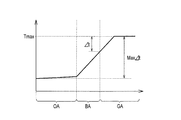
- FIG. 3 is a graph showing the temperature distribution during rapid start-up.
- FIG. 4 is a graph showing the temperature distribution during rapid start-up.
- FIG. 5 is a partial cross-sectional view of the fuel battery cell according to the second embodiment of the present invention.
- Solid oxide fuel cells are a type of fuel cell that is a device that converts scientific energy into electrical energy through an electrochemical reaction. As shown in FIGS. 1 and 2, the solid oxide fuel cell according to the present embodiment includes a plate-shaped metal support 1 and a pair of separators 2 and 2 that sandwich the metal support 1 from both sides. I have.
- the laminated metal support 1 and separator 2 are sandwiched by a pair of seal frames 3 from both sides (both ends in the laminating direction).
- the seal frame 3 sandwiches and supports the outer edge (outer peripheral area OA) of the metal support 1 and sandwiches and supports the outer edge of the separator 2.
- the metal support 1 and the seal frame 3 are fixed by an insulating layer 5 made of an adhesive or the like with a sealant 4 interposed therebetween.
- the metal support 1 and the separator 2, and the separator 2 and the seal frame 3 are fixed by welding.
- a welded portion 6 between the metal support 1 and the separator 2 and a welded portion 7 between the separator 2 and the seal frame 3 are indicated by triangles.
- the power generation cell 8 is disposed on one side of the both sides of the metal support 1.
- the power generation cell 8 is formed as a laminate of a fuel electrode (anode electrode) 9, a solid oxide electrolyte 10, and an air electrode (cathode electrode) 11.
- the fuel electrode 9 and the air electrode 11 are disposed with the electrolyte 10 interposed therebetween.
- the power generation cell 8 is stacked so that the fuel electrode 9 is in contact with the metal support 1, and a current collection auxiliary layer 12 is further stacked on the air electrode 11 of the power generation cell 8. In this way, the metal support 1 supports the power generation cell 8.
- a portion corresponding to an active region contributing to power generation in the power generation cell 8 is formed in a wave shape, and a contact portion 2 a that contacts the metal support 1 and a contact portion that contacts the current collecting auxiliary layer 12. 2b are alternately arranged.
- Fuel gas or oxidant gas is introduced into the space defined by the corrugated portion of the separator 2 and the metal support 1 and the space defined by the corrugated portion of the separator 2 and the current collecting auxiliary layer 12. It is supposed to flow. That is, the separator 2 has a function of partitioning and forming the fuel flow path 13 or the air flow path 14 between the metal support 1, the power generation cell 8 and the current collection auxiliary layer 12. In addition, the separator 2 has a function of collecting electricity generated in the power generation cell 8.
- the separator 2 By welding the contact portion 2a of the separator 2 to the metal support 1, the separator 2 is fixed to the metal support 1, and by welding the contact portion 2b of the separator 2 to the current collecting auxiliary layer 12, The separator 2 is fixed to the current collection auxiliary layer 12.
- a welded portion 15 between the separator 2 and the metal support 1 and a welded portion 16 between the separator 2 and the current collecting auxiliary layer 12 are indicated by triangles.
- the metal support 1 is formed of a conductive material for the purpose of improving the output per unit area of the fuel cell, but gas permeability is also required to supply fuel gas or oxidant gas to the electrode.
- the metal support 1 is formed of, for example, a porous metal substrate formed by sintering metal particles.
- manifold parts M and M for supplying and discharging fuel gas or air gas, and fuel gas or oxidant from the manifold parts M and M to the power generation cell 8 are provided.
- a diffuser part D which is a gas distribution region, is formed.
- the diffuser portion D is provided with a spacer 17 and a plurality of protrusions 18.
- the metal support 1 is formed in a power generation area GA in which the power generation cell 8 is disposed, and a non-power generation buffer area BA in which the power generation cell 8 is not provided and is formed in an area outside the power generation area GA in the in-plane direction. And an outer peripheral area OA formed in a further outer area of the buffer area BA.
- the metal support 1 is configured such that the thickness of the power generation area GA and the buffer area BA is smaller than the thickness of the outer peripheral area OA. That is, the metal support 1 is configured such that the thickness of the outer peripheral area OA is larger than the thickness of the power generation area GA and the buffer area BA.
- the portions where the buffer areas BA are provided are hatched.
- the outer peripheral area OA of the metal support 1 is a portion sandwiched from both sides by the seal frame 3, and is a dense layer that does not allow gas to permeate in the thickness direction.
- the power generation area GA of the metal support 1 is a porous layer so that gas can pass in the thickness direction.
- the outer peripheral area OA may be densified by pressing, or may be densified by sintering metal grains having a relatively large grain size.
- the buffer area BA of the metal support 1 is originally a porous layer, but unlike the power generation area GA, the pores of the metal support 1 in the buffer area BA have a thermal conductivity higher than that of the material forming the metal support 1. Filled with low filling material. By doing so, the thermal conductivity of the buffer area BA is made lower than the thermal conductivity of the power generation area GA, and the heat capacity of the buffer area BA is made larger than the heat capacity of the power generation area GA. Further, by adjusting the thermal conductivity of the forming material of the metal support 1 and the thermal conductivity of the filling material, the thermal conductivity of the buffer area BA is made lower than the thermal conductivity of the outer peripheral area OA. The heat capacity of BA is made larger than the heat capacity of the outer peripheral area OA.
- the filling material examples include ceramics such as yttria stabilized zirconia (YSZ), lanthanum strontium magnesium galade (LSGM), samarium doptoceria (SDC), gadolinium doptoceria (GDC), and scandium stabilized zirconia (SSZ). Materials can be used.
- YSZ yttria stabilized zirconia
- LSGM lanthanum strontium magnesium galade
- SDC samarium doptoceria
- GDC gadolinium doptoceria
- SSZ scandium stabilized zirconia
- region BA of the metal support body 1 is used as the dense layer which gas does not permeate
- an edge seal structure is formed in the electrolyte 10 by extending the end of the electrolyte 10 of the power generation cell 8 to the buffer area BA.
- a flow path space 19 is formed in a space adjacent to the buffer area BA of the metal support 1, and a flow path space adjacent to the power generation area GA (that is, the fuel flow path 13 or the air flow path) is formed in the flow path space 19.
- the gas may be distributed so that a gas having the same temperature as the gas flowing in 14) flows.
- a fuel gas such as hydrogen or hydrocarbon is supplied to the fuel electrode 9 (fuel channel 13), while an oxidant gas such as air or oxygen is supplied to the air electrode 11.
- an oxidant gas such as air or oxygen is supplied to the air electrode 11.
- a solid oxide fuel cell having a stack structure is formed by laminating the metal support 1 and the separator 2 in multiple layers.
- the rapid start condition was 10.78 ° C./second, and the temperature distribution of the metal support after 70 seconds from the rapid start was simulated.
- Example 1 a case where a high-temperature gas was not allowed to flow in the channel space adjacent to the buffer region was simulated, and in Example 2, a case where a high-temperature gas was allowed to flow in the channel space adjacent to the buffer region was simulated.
- Example 1 the maximum temperature Tmax of the metal support was 900 ° C., and the maximum temperature difference Max ⁇ t was 690 ° C.
- Example 1 From the result of Example 1 (FIG. 3), the temperature gradient in the power generation region is smaller than that in the case where no buffer region is provided, and the temperature difference ⁇ t at the end of the power generation cell is compared with that in the case where no buffer region is provided. It turned out that it became small. Further, from the results of Example 2 (FIG. 4), it was found that the temperature gradient in the power generation region becomes zero, and the temperature difference ⁇ t at the end of the power generation cell becomes zero.
- the solid oxide fuel cell according to this embodiment includes a metal support 1 that is formed of a porous metal substrate and supports a power generation cell.
- the metal support 1 has a power generation area GA in which the power generation cells 8 are disposed, and a buffer area BA formed outside the power generation area GA in the in-plane direction.
- the pores of the metal support 1 in the buffer area BA are filled with a material having a lower thermal conductivity than the material for forming the metal support 1.
- the thermal conductivity of the buffer area BA lower than the thermal conductivity of the power generation area GA, it is difficult for heat to be transferred from the power generation area GA to the outside at the time of rapid start, and the temperature gradient at the end of the power generation area GA is reduced. Can be small. Thereby, the temperature difference ⁇ t at the end of the power generation cell 8 facing the power generation area GA is reduced, and the thermal stress generated at the end of the power generation cell 8 is reduced. For this reason, generation
- the metal support 1 in the buffer area BA is a dense layer through which no gas permeates in the thickness direction.
- a gas having the same temperature as the gas flowing in the flow path space (the fuel flow path 13 or the air flow path 14) adjacent to the power generation area GA is supplied to the flow path space 19 adjacent to the buffer area BA.
- the temperature of the flow path space 19 adjacent to the buffer area BA is equal to the temperature of the flow path space (fuel flow path 13 or air flow path 14) adjacent to the power generation area GA, the end of the power generation area GA And the temperature of the central part are equivalent. Thereby, the temperature difference ⁇ t at the end of the power generation cell 8 facing the power generation area GA becomes smaller, and the thermal stress generated at the end of the power generation cell 8 is further reduced.
- the pore diameter of the metal support 1 in the vicinity of the boundary 20 between the buffer area BA and the power generation area GA is the metal in the power generation area GA. It is comprised so that it may become smaller than the pore diameter of the support body 1.
- an edge seal structure is formed in the electrolyte 10 by extending the end portion of the electrolyte 10 of the power generation cell 8 to the boundary vicinity portion 20.
- the pore diameter of the metal support 1 in the vicinity of the boundary 20 between the buffer area BA and the power generation area GA is larger than the pore diameter of the metal support 1 in the power generation area GA. small.
- the density in the boundary vicinity portion 20 is increased after firing, and the filling material filled in the pores of the metal support 1 in the buffer region BA flows into the pores of the metal support 1 in the power generation region GA. Can be prevented.
Landscapes
- Life Sciences & Earth Sciences (AREA)
- Engineering & Computer Science (AREA)
- Manufacturing & Machinery (AREA)
- Sustainable Development (AREA)
- Sustainable Energy (AREA)
- Chemical & Material Sciences (AREA)
- Chemical Kinetics & Catalysis (AREA)
- Electrochemistry (AREA)
- General Chemical & Material Sciences (AREA)
- Fuel Cell (AREA)
Abstract
Description
本発明の第一実施形態に係る固体酸化物型燃料電池を図1から図4に基づいて説明する。
金属支持体の形状、形成材料の物性値、燃料電池内部を流れる高温のガスの温度、燃料電池外部の温度などの各データに基づき、計算機により金属支持体の温度分布のシミュレーションを行った。
急速起動条件(加熱条件)を10.78℃/秒として、急速起動から70秒経過した後の金属支持体の温度分布をシミュレーションした。
実施例1および実施例2において、金属支持体の最高温度Tmaxは900℃であり、最大温度差MaxΔtは690℃であった。
本発明の第二実施形態に係る固体酸化物型燃料電池を図5に基づいて説明する。なお、前述の第一実施形態と同一の部分は同一符号を付することによってその説明を省略する。
2 セパレータ
8 発電セル
19 緩衝領域と隣接する流路空間
20 境界近傍部分
OA 外周領域
GA 発電領域
BA 緩衝領域
Claims (4)
- 多孔質金属基板により形成され、発電セルを支持する金属支持体を備え、
前記金属支持体は、発電セルが配置される発電領域と、前記発電領域に対して面内方向の外側に形成される緩衝領域と、を有し、
前記緩衝領域における前記金属支持体の気孔には、前記金属支持体の形成材料よりも熱伝導率が低い材料が充填されている
ことを特徴とする固体酸化物型燃料電池。 - 前記緩衝領域における前記金属支持体は、厚さ方向にガスが透過しない緻密層とされることを特徴とする請求項1に記載の固体酸化物型燃料電池。
- 前記緩衝領域と隣接する流路空間に、前記発電領域と隣接する流路空間に流すガスと同等の温度のガスを流すことを特徴とする請求項2に記載の固体酸化物型燃料電池。
- 前記緩衝領域の前記発電領域との境界近傍部分における前記金属支持体の気孔径は、前記発電領域における前記金属支持体の気孔径よりも小さいことを特徴とする請求項1から3のいずれか一項に記載の固体酸化物型燃料電池。
Priority Applications (7)
| Application Number | Priority Date | Filing Date | Title |
|---|---|---|---|
| JP2017522790A JP6521064B2 (ja) | 2015-06-09 | 2015-06-09 | 固体酸化物型燃料電池 |
| CN201580080761.5A CN107615540B (zh) | 2015-06-09 | 2015-06-09 | 固体氧化物型燃料电池 |
| BR112017026684-9A BR112017026684B1 (pt) | 2015-06-09 | 2015-06-09 | Célula de combustível de oxido sólido |
| US15/580,418 US10483579B2 (en) | 2015-06-09 | 2015-06-09 | Solid oxide fuel cell |
| CA2988369A CA2988369C (en) | 2015-06-09 | 2015-06-09 | Solid oxide fuel cell |
| EP15894908.1A EP3309883B1 (en) | 2015-06-09 | 2015-06-09 | Solid-oxide fuel cell |
| PCT/JP2015/066611 WO2016199223A1 (ja) | 2015-06-09 | 2015-06-09 | 固体酸化物型燃料電池 |
Applications Claiming Priority (1)
| Application Number | Priority Date | Filing Date | Title |
|---|---|---|---|
| PCT/JP2015/066611 WO2016199223A1 (ja) | 2015-06-09 | 2015-06-09 | 固体酸化物型燃料電池 |
Publications (1)
| Publication Number | Publication Date |
|---|---|
| WO2016199223A1 true WO2016199223A1 (ja) | 2016-12-15 |
Family
ID=57503277
Family Applications (1)
| Application Number | Title | Priority Date | Filing Date |
|---|---|---|---|
| PCT/JP2015/066611 Ceased WO2016199223A1 (ja) | 2015-06-09 | 2015-06-09 | 固体酸化物型燃料電池 |
Country Status (7)
| Country | Link |
|---|---|
| US (1) | US10483579B2 (ja) |
| EP (1) | EP3309883B1 (ja) |
| JP (1) | JP6521064B2 (ja) |
| CN (1) | CN107615540B (ja) |
| BR (1) | BR112017026684B1 (ja) |
| CA (1) | CA2988369C (ja) |
| WO (1) | WO2016199223A1 (ja) |
Cited By (7)
| Publication number | Priority date | Publication date | Assignee | Title |
|---|---|---|---|---|
| JP2019036443A (ja) * | 2017-08-10 | 2019-03-07 | 日産自動車株式会社 | 燃料電池スタックのセル構造および燃料電池セルのたわみ規制方法 |
| WO2019106765A1 (ja) * | 2017-11-29 | 2019-06-06 | 日産自動車株式会社 | 燃料電池スタック |
| JP2019186119A (ja) * | 2018-04-13 | 2019-10-24 | 日産自動車株式会社 | 燃料電池スタック |
| JP2021180165A (ja) * | 2020-05-15 | 2021-11-18 | 日産自動車株式会社 | 燃料電池セル構造及び燃料電池セル構造の製造方法 |
| JP2022511936A (ja) * | 2018-12-20 | 2022-02-01 | セレス インテレクチュアル プロパティー カンパニー リミテッド | 燃料電池ユニット及び燃料電池スタック |
| JPWO2022259372A1 (ja) * | 2021-06-08 | 2022-12-15 | ||
| JPWO2023012979A1 (ja) * | 2021-08-05 | 2023-02-09 |
Citations (4)
| Publication number | Priority date | Publication date | Assignee | Title |
|---|---|---|---|---|
| JP2005166422A (ja) * | 2003-12-02 | 2005-06-23 | Nissan Motor Co Ltd | 固体酸化物形燃料電池用セル、セル板及びその製造方法 |
| JP2009505370A (ja) * | 2005-08-17 | 2009-02-05 | ユーティーシー パワー コーポレイション | 移動式発電機用の固体酸化物形燃料セルスタック |
| JP2010534901A (ja) * | 2007-07-26 | 2010-11-11 | プランゼー ソシエタス エウロペア | 燃料電池とその製造方法 |
| WO2013042542A1 (ja) * | 2011-09-22 | 2013-03-28 | 本田技研工業株式会社 | 燃料電池用樹脂枠付き電解質膜・電極構造体 |
Family Cites Families (17)
| Publication number | Priority date | Publication date | Assignee | Title |
|---|---|---|---|---|
| DE1796089A1 (de) * | 1967-08-31 | 1972-04-13 | Cie Francaise De Raffinage S A | Batterie von Brennstoffelementen mit festem Elektrolyt und Verfahren zur Herstellung dieser Batterien |
| NL9401159A (nl) * | 1994-07-13 | 1996-02-01 | Stork Screens Bv | Schuimprodukt. |
| JPH10199555A (ja) | 1997-01-06 | 1998-07-31 | Toho Gas Co Ltd | 固体電解質型燃料電池のガスシール構造 |
| WO2002097667A2 (en) * | 2001-05-31 | 2002-12-05 | Lixto Software Gmbh | Visual and interactive wrapper generation, automated information extraction from web pages, and translation into xml |
| JP2004207088A (ja) * | 2002-12-26 | 2004-07-22 | Nissan Motor Co Ltd | ガス透過性基体及びこれを用いた固体酸化物形燃料電池 |
| GB2410151A (en) * | 2004-01-15 | 2005-07-20 | Rf Tags Ltd | A radio frequency identification tag with means sensitive to light for controlling communication between rfid tag and reader |
| US7226687B2 (en) * | 2004-05-08 | 2007-06-05 | Meacham G B Kirby | Fuel cell assemblies using metallic bipolar separators |
| US7632593B2 (en) | 2005-05-03 | 2009-12-15 | Uchicago Argonne, Llc | Bipolar plate supported solid oxide fuel cell with a sealed anode compartment |
| US20060286431A1 (en) | 2005-06-15 | 2006-12-21 | National Central University | Flow channel on interconnect of planar solid oxide fuel cell |
| US9600236B2 (en) * | 2006-07-25 | 2017-03-21 | Vivante Corporation | Systems and methods for computing mathematical functions |
| ATE549762T1 (de) | 2007-10-05 | 2012-03-15 | Topsoe Fuel Cell As | Dichtung für eine poröse metallfolie enthaltende brennstoffzelle |
| KR101305506B1 (ko) * | 2008-07-14 | 2013-09-05 | 삼성전자주식회사 | 화상형성장치 및 그 제어방법 |
| US20100086824A1 (en) * | 2008-09-03 | 2010-04-08 | Michael Homel | Assemblies of hollow electrode electrochemical devices |
| FR2971248B1 (fr) * | 2011-02-04 | 2013-08-16 | Rhodia Operations | Preparation de diamine via la preparation d'aminonitrile |
| US8518598B1 (en) * | 2012-04-25 | 2013-08-27 | Utc Power Corporation | Solid oxide fuel cell power plant with a molten metal anode |
| ES2887360T3 (es) * | 2012-07-23 | 2021-12-22 | Mo Sci Corp | Composiciones viscosas de vidrio de sellado en una pila de combustible de óxido sólido |
| KR20140053568A (ko) * | 2012-10-26 | 2014-05-08 | 삼성전기주식회사 | 고체산화물 연료전지 모듈 |
-
2015
- 2015-06-09 JP JP2017522790A patent/JP6521064B2/ja active Active
- 2015-06-09 CN CN201580080761.5A patent/CN107615540B/zh active Active
- 2015-06-09 US US15/580,418 patent/US10483579B2/en active Active
- 2015-06-09 CA CA2988369A patent/CA2988369C/en active Active
- 2015-06-09 WO PCT/JP2015/066611 patent/WO2016199223A1/ja not_active Ceased
- 2015-06-09 BR BR112017026684-9A patent/BR112017026684B1/pt not_active IP Right Cessation
- 2015-06-09 EP EP15894908.1A patent/EP3309883B1/en active Active
Patent Citations (4)
| Publication number | Priority date | Publication date | Assignee | Title |
|---|---|---|---|---|
| JP2005166422A (ja) * | 2003-12-02 | 2005-06-23 | Nissan Motor Co Ltd | 固体酸化物形燃料電池用セル、セル板及びその製造方法 |
| JP2009505370A (ja) * | 2005-08-17 | 2009-02-05 | ユーティーシー パワー コーポレイション | 移動式発電機用の固体酸化物形燃料セルスタック |
| JP2010534901A (ja) * | 2007-07-26 | 2010-11-11 | プランゼー ソシエタス エウロペア | 燃料電池とその製造方法 |
| WO2013042542A1 (ja) * | 2011-09-22 | 2013-03-28 | 本田技研工業株式会社 | 燃料電池用樹脂枠付き電解質膜・電極構造体 |
Non-Patent Citations (1)
| Title |
|---|
| See also references of EP3309883A4 * |
Cited By (15)
| Publication number | Priority date | Publication date | Assignee | Title |
|---|---|---|---|---|
| JP2019036443A (ja) * | 2017-08-10 | 2019-03-07 | 日産自動車株式会社 | 燃料電池スタックのセル構造および燃料電池セルのたわみ規制方法 |
| JPWO2019106765A1 (ja) * | 2017-11-29 | 2020-10-22 | 日産自動車株式会社 | 燃料電池スタック |
| WO2019106765A1 (ja) * | 2017-11-29 | 2019-06-06 | 日産自動車株式会社 | 燃料電池スタック |
| JP7087616B2 (ja) | 2018-04-13 | 2022-06-21 | 日産自動車株式会社 | 燃料電池スタック |
| JP2019186119A (ja) * | 2018-04-13 | 2019-10-24 | 日産自動車株式会社 | 燃料電池スタック |
| JP2022511936A (ja) * | 2018-12-20 | 2022-02-01 | セレス インテレクチュアル プロパティー カンパニー リミテッド | 燃料電池ユニット及び燃料電池スタック |
| JP7509778B2 (ja) | 2018-12-20 | 2024-07-02 | セレス インテレクチュアル プロパティー カンパニー リミテッド | 燃料電池ユニット及び燃料電池スタック |
| JP2021180165A (ja) * | 2020-05-15 | 2021-11-18 | 日産自動車株式会社 | 燃料電池セル構造及び燃料電池セル構造の製造方法 |
| JP7501091B2 (ja) | 2020-05-15 | 2024-06-18 | 日産自動車株式会社 | 燃料電池セル構造及び燃料電池セル構造の製造方法 |
| JPWO2022259372A1 (ja) * | 2021-06-08 | 2022-12-15 | ||
| WO2022259372A1 (ja) * | 2021-06-08 | 2022-12-15 | 日産自動車株式会社 | 固体酸化物形燃料電池および固体酸化物形燃料電池の製造方法 |
| JP7655383B2 (ja) | 2021-06-08 | 2025-04-02 | 日産自動車株式会社 | 固体酸化物形燃料電池および固体酸化物形燃料電池の製造方法 |
| JPWO2023012979A1 (ja) * | 2021-08-05 | 2023-02-09 | ||
| WO2023012979A1 (ja) * | 2021-08-05 | 2023-02-09 | 日産自動車株式会社 | 燃料電池セル及び燃料電池セルの製造方法 |
| JP7670138B2 (ja) | 2021-08-05 | 2025-04-30 | 日産自動車株式会社 | 燃料電池セル及び燃料電池セルの製造方法 |
Also Published As
| Publication number | Publication date |
|---|---|
| EP3309883A4 (en) | 2018-07-25 |
| CN107615540B (zh) | 2018-10-02 |
| JPWO2016199223A1 (ja) | 2018-04-12 |
| BR112017026684A2 (ja) | 2018-08-14 |
| CA2988369C (en) | 2019-07-16 |
| US20180175424A1 (en) | 2018-06-21 |
| EP3309883B1 (en) | 2020-09-30 |
| US10483579B2 (en) | 2019-11-19 |
| JP6521064B2 (ja) | 2019-05-29 |
| CN107615540A (zh) | 2018-01-19 |
| CA2988369A1 (en) | 2016-12-15 |
| BR112017026684B1 (pt) | 2022-07-26 |
| EP3309883A1 (en) | 2018-04-18 |
Similar Documents
| Publication | Publication Date | Title |
|---|---|---|
| JP6521064B2 (ja) | 固体酸化物型燃料電池 | |
| JP5088539B2 (ja) | 固体酸化物形燃料電池 | |
| CN107431216B (zh) | 电化学反应单元及燃料电池堆 | |
| JP6139231B2 (ja) | 固体酸化物形電気化学セルスタック構造体および水素電力貯蔵システム | |
| JP7368402B2 (ja) | 電気化学反応単セルおよび電気化学反応セルスタック | |
| JP2013012397A (ja) | 固体酸化物形燃料電池セルおよび燃料電池モジュール | |
| JP5881594B2 (ja) | 燃料電池スタック及びその製造方法 | |
| JP6702585B2 (ja) | 平板型電気化学セルスタック | |
| JP5116182B1 (ja) | 燃料電池の構造体 | |
| JP6560621B2 (ja) | 電気化学反応単セル、インターコネクタ−電気化学反応単セル複合体、および、電気化学反応セルスタック | |
| JP6294134B2 (ja) | 燃料電池スタック | |
| CN108701838A (zh) | 燃料电池发电单元和燃料电池堆 | |
| JP5846936B2 (ja) | 燃料電池 | |
| JP6926193B2 (ja) | 平板型電気化学セルスタック | |
| JP2010238437A (ja) | 平板型固体酸化物形燃料電池用の固体電解質及び平板型固体酸化物形燃料電池 | |
| JP2024058262A (ja) | 電気化学反応単セル | |
| JP7087624B2 (ja) | 燃料電池スタック | |
| JP5272571B2 (ja) | 燃料電池の製造方法、及び、燃料電池 | |
| JP6835631B2 (ja) | 電気化学反応単セルおよび電気化学反応セルスタック | |
| JP6389959B2 (ja) | 燃料電池スタックおよび燃料電池スタックの製造方法 | |
| JP6780920B2 (ja) | 燃料電池単セルおよび燃料電池スタック | |
| JP2008198507A (ja) | 膜電極接合体、燃料電池、および、触媒インク | |
| JP5277942B2 (ja) | 燃料電池用電極、および、燃料電池 | |
| US20140030629A1 (en) | Solid oxide fuel cell | |
| JP2017224525A (ja) | 集電部材−電気化学反応単セル複合体および電気化学反応セルスタック |
Legal Events
| Date | Code | Title | Description |
|---|---|---|---|
| 121 | Ep: the epo has been informed by wipo that ep was designated in this application |
Ref document number: 15894908 Country of ref document: EP Kind code of ref document: A1 |
|
| ENP | Entry into the national phase |
Ref document number: 2017522790 Country of ref document: JP Kind code of ref document: A |
|
| ENP | Entry into the national phase |
Ref document number: 2988369 Country of ref document: CA |
|
| WWE | Wipo information: entry into national phase |
Ref document number: 15580418 Country of ref document: US |
|
| NENP | Non-entry into the national phase |
Ref country code: DE |
|
| WWE | Wipo information: entry into national phase |
Ref document number: 2015894908 Country of ref document: EP |
|
| REG | Reference to national code |
Ref country code: BR Ref legal event code: B01A Ref document number: 112017026684 Country of ref document: BR |
|
| ENP | Entry into the national phase |
Ref document number: 112017026684 Country of ref document: BR Kind code of ref document: A2 Effective date: 20171211 |