WO2016199786A1 - 車両用画像表示機能付きミラーおよび製造方法 - Google Patents
車両用画像表示機能付きミラーおよび製造方法 Download PDFInfo
- Publication number
- WO2016199786A1 WO2016199786A1 PCT/JP2016/066981 JP2016066981W WO2016199786A1 WO 2016199786 A1 WO2016199786 A1 WO 2016199786A1 JP 2016066981 W JP2016066981 W JP 2016066981W WO 2016199786 A1 WO2016199786 A1 WO 2016199786A1
- Authority
- WO
- WIPO (PCT)
- Prior art keywords
- image display
- mirror
- liquid crystal
- layer
- display function
- Prior art date
- Legal status (The legal status is an assumption and is not a legal conclusion. Google has not performed a legal analysis and makes no representation as to the accuracy of the status listed.)
- Ceased
Links
Images
Classifications
-
- B—PERFORMING OPERATIONS; TRANSPORTING
- B60—VEHICLES IN GENERAL
- B60R—VEHICLES, VEHICLE FITTINGS, OR VEHICLE PARTS, NOT OTHERWISE PROVIDED FOR
- B60R1/00—Optical viewing arrangements; Real-time viewing arrangements for drivers or passengers using optical image capturing systems, e.g. cameras or video systems specially adapted for use in or on vehicles
- B60R1/02—Rear-view mirror arrangements
- B60R1/04—Rear-view mirror arrangements mounted inside vehicle
-
- G—PHYSICS
- G09—EDUCATION; CRYPTOGRAPHY; DISPLAY; ADVERTISING; SEALS
- G09F—DISPLAYING; ADVERTISING; SIGNS; LABELS OR NAME-PLATES; SEALS
- G09F21/00—Mobile visual advertising
- G09F21/04—Mobile visual advertising by land vehicles
- G09F21/049—Mobile visual advertising by land vehicles giving information to passengers inside the vehicles
-
- B—PERFORMING OPERATIONS; TRANSPORTING
- B60—VEHICLES IN GENERAL
- B60R—VEHICLES, VEHICLE FITTINGS, OR VEHICLE PARTS, NOT OTHERWISE PROVIDED FOR
- B60R1/00—Optical viewing arrangements; Real-time viewing arrangements for drivers or passengers using optical image capturing systems, e.g. cameras or video systems specially adapted for use in or on vehicles
- B60R1/02—Rear-view mirror arrangements
- B60R1/08—Rear-view mirror arrangements involving special optical features, e.g. avoiding blind spots, e.g. convex mirrors; Side-by-side associations of rear-view and other mirrors
- B60R1/083—Anti-glare mirrors, e.g. "day-night" mirrors
-
- B—PERFORMING OPERATIONS; TRANSPORTING
- B60—VEHICLES IN GENERAL
- B60R—VEHICLES, VEHICLE FITTINGS, OR VEHICLE PARTS, NOT OTHERWISE PROVIDED FOR
- B60R1/00—Optical viewing arrangements; Real-time viewing arrangements for drivers or passengers using optical image capturing systems, e.g. cameras or video systems specially adapted for use in or on vehicles
- B60R1/12—Mirror assemblies combined with other articles, e.g. clocks
-
- G—PHYSICS
- G02—OPTICS
- G02B—OPTICAL ELEMENTS, SYSTEMS OR APPARATUS
- G02B5/00—Optical elements other than lenses
- G02B5/08—Mirrors
-
- G—PHYSICS
- G02—OPTICS
- G02B—OPTICAL ELEMENTS, SYSTEMS OR APPARATUS
- G02B5/00—Optical elements other than lenses
- G02B5/30—Polarising elements
-
- G—PHYSICS
- G02—OPTICS
- G02F—OPTICAL DEVICES OR ARRANGEMENTS FOR THE CONTROL OF LIGHT BY MODIFICATION OF THE OPTICAL PROPERTIES OF THE MEDIA OF THE ELEMENTS INVOLVED THEREIN; NON-LINEAR OPTICS; FREQUENCY-CHANGING OF LIGHT; OPTICAL LOGIC ELEMENTS; OPTICAL ANALOGUE/DIGITAL CONVERTERS
- G02F1/00—Devices or arrangements for the control of the intensity, colour, phase, polarisation or direction of light arriving from an independent light source, e.g. switching, gating or modulating; Non-linear optics
- G02F1/01—Devices or arrangements for the control of the intensity, colour, phase, polarisation or direction of light arriving from an independent light source, e.g. switching, gating or modulating; Non-linear optics for the control of the intensity, phase, polarisation or colour
- G02F1/13—Devices or arrangements for the control of the intensity, colour, phase, polarisation or direction of light arriving from an independent light source, e.g. switching, gating or modulating; Non-linear optics for the control of the intensity, phase, polarisation or colour based on liquid crystals, e.g. single liquid crystal display cells
- G02F1/133—Constructional arrangements; Operation of liquid crystal cells; Circuit arrangements
- G02F1/1333—Constructional arrangements; Manufacturing methods
- G02F1/1335—Structural association of cells with optical devices, e.g. polarisers or reflectors
- G02F1/133528—Polarisers
- G02F1/133536—Reflective polarizers
-
- G—PHYSICS
- G02—OPTICS
- G02F—OPTICAL DEVICES OR ARRANGEMENTS FOR THE CONTROL OF LIGHT BY MODIFICATION OF THE OPTICAL PROPERTIES OF THE MEDIA OF THE ELEMENTS INVOLVED THEREIN; NON-LINEAR OPTICS; FREQUENCY-CHANGING OF LIGHT; OPTICAL LOGIC ELEMENTS; OPTICAL ANALOGUE/DIGITAL CONVERTERS
- G02F1/00—Devices or arrangements for the control of the intensity, colour, phase, polarisation or direction of light arriving from an independent light source, e.g. switching, gating or modulating; Non-linear optics
- G02F1/01—Devices or arrangements for the control of the intensity, colour, phase, polarisation or direction of light arriving from an independent light source, e.g. switching, gating or modulating; Non-linear optics for the control of the intensity, phase, polarisation or colour
- G02F1/13—Devices or arrangements for the control of the intensity, colour, phase, polarisation or direction of light arriving from an independent light source, e.g. switching, gating or modulating; Non-linear optics for the control of the intensity, phase, polarisation or colour based on liquid crystals, e.g. single liquid crystal display cells
- G02F1/133—Constructional arrangements; Operation of liquid crystal cells; Circuit arrangements
- G02F1/1333—Constructional arrangements; Manufacturing methods
- G02F1/1335—Structural association of cells with optical devices, e.g. polarisers or reflectors
- G02F1/13363—Birefringent elements, e.g. for optical compensation
- G02F1/133638—Waveplates, i.e. plates with a retardation value of lambda/n
-
- G—PHYSICS
- G09—EDUCATION; CRYPTOGRAPHY; DISPLAY; ADVERTISING; SEALS
- G09F—DISPLAYING; ADVERTISING; SIGNS; LABELS OR NAME-PLATES; SEALS
- G09F9/00—Indicating arrangements for variable information in which the information is built-up on a support by selection or combination of individual elements
- G09F9/30—Indicating arrangements for variable information in which the information is built-up on a support by selection or combination of individual elements in which the desired character or characters are formed by combining individual elements
- G09F9/35—Indicating arrangements for variable information in which the information is built-up on a support by selection or combination of individual elements in which the desired character or characters are formed by combining individual elements being liquid crystals
-
- B—PERFORMING OPERATIONS; TRANSPORTING
- B60—VEHICLES IN GENERAL
- B60R—VEHICLES, VEHICLE FITTINGS, OR VEHICLE PARTS, NOT OTHERWISE PROVIDED FOR
- B60R1/00—Optical viewing arrangements; Real-time viewing arrangements for drivers or passengers using optical image capturing systems, e.g. cameras or video systems specially adapted for use in or on vehicles
- B60R1/12—Mirror assemblies combined with other articles, e.g. clocks
- B60R2001/1253—Mirror assemblies combined with other articles, e.g. clocks with cameras, video cameras or video screens
-
- G—PHYSICS
- G02—OPTICS
- G02B—OPTICAL ELEMENTS, SYSTEMS OR APPARATUS
- G02B5/00—Optical elements other than lenses
- G02B5/30—Polarising elements
- G02B5/3016—Polarising elements involving passive liquid crystal elements
Definitions
- the present invention relates to a mirror with an image display function for a vehicle and a manufacturing method thereof.
- Patent Document 1 describes a mirror with a vehicle image display function capable of displaying an image such as an image captured by a vehicle-mounted camera on a vehicle mirror.
- a liquid crystal display device is provided inside the housing of the vehicle mirror, and an image is displayed through a half mirror provided on the front surface of the vehicle mirror. The image display on the mirror is realized.
- An object of the present invention is to provide a mirror with a vehicle image display function for which the visibility of an image is hardly lowered by external light, and a method for manufacturing the same.
- a mirror with an image display function for vehicles Including image display device and half mirror,
- the half mirror includes a reflective layer,
- the said mirror for image display functions for vehicles in which the said reflection layer inclines with respect to the image display part surface of the said image display apparatus.
- the mirror with an image display function includes a quarter wavelength plate, The mirror with an image display function for vehicles according to [4] or [5], including the image display device, the quarter-wave plate, and the circularly polarizing reflection layer in this order.
- the half mirror includes a front plate, The mirror with an image display function for a vehicle according to any one of [1] to [8], wherein the mirror with an image display function for a vehicle includes the image display device, the reflective layer, and the front plate in this order.
- the mirror with an image display function for a vehicle according to any one of [1] to [11], wherein the image display device and the half mirror are integrated by a frame provided on a side surface of the half mirror.
- a method of manufacturing a mirror with a vehicle image display function The manufacturing method including arrange
- a mirror with an image display function for a vehicle in which the visibility of an image is hardly deteriorated by external light and a method for manufacturing the same are provided.
- ⁇ is used to mean that the numerical values described before and after it are included as a lower limit value and an upper limit value.
- an angle such as “45 °”, “parallel”, “vertical” or “orthogonal” is within a range where the difference from the exact angle is less than 5 ° unless otherwise specified. Means. The difference from the exact angle is preferably less than 4 °, more preferably less than 3 °.
- (meth) acrylate is used to mean “one or both of acrylate and methacrylate”.
- “selective” for circularly polarized light means that either the right circularly polarized light component or the left circularly polarized light component has more light than the other circularly polarized light component.
- the degree of circular polarization of light is preferably 0.3 or more, more preferably 0.6 or more, and even more preferably 0.8 or more. More preferably, it is substantially 1.0.
- sense for circularly polarized light means right circularly polarized light or left circularly polarized light.
- the sense of circularly polarized light is right-handed circularly polarized light when the electric field vector tip turns clockwise as time increases when viewed as the light travels toward you, and left when it turns counterclockwise. Defined as being circularly polarized.
- the term “sense” is sometimes used for the twist direction of the spiral of the cholesteric liquid crystal.
- the twist direction (sense) of the spiral of the cholesteric liquid crystal is right, it reflects right circularly polarized light and transmits left circularly polarized light.
- the sense When the sense is left, it reflects left circularly polarized light and transmits right circularly polarized light.
- Visible light is light having a wavelength that can be seen by human eyes among electromagnetic waves, and indicates light having a wavelength range of 380 nm to 780 nm.
- Infrared rays are electromagnetic waves in the wavelength range that are longer than visible rays and shorter than radio waves.
- near infrared light is an electromagnetic wave having a wavelength range of 780 nm to 2500 nm.
- the term “image” for the mirror with an image display function means an image that can be viewed and observed from the front side when the image is displayed on the image display unit of the image display device.
- the term “mirror reflection image” for a mirror with an image display function means an image that can be viewed and observed from the front side when no image is displayed on the image display unit of the image display device. .
- the front phase difference is a value measured using an AxoScan manufactured by Axometrics.
- the measurement wavelength is 550 nm unless otherwise specified.
- the front phase difference is a value measured with KOBRA 21ADH or WR (manufactured by Oji Scientific Instruments Co., Ltd.) by injecting light in the visible light wavelength region such as the central wavelength of selective reflection of the cholesteric liquid crystal layer in the film normal direction. It can also be used.
- the wavelength selection filter can be exchanged manually, or the measurement value can be converted by a program or the like.
- the mirror with an image display function for vehicles can be used, for example, as a vehicle rearview mirror (inner mirror).
- the mirror with an image display function for a vehicle may have a frame, a housing, a support arm for attaching to a vehicle body, and the like for use as a rearview mirror.
- the vehicle image display function-equipped mirror may be formed for incorporation into a room mirror. In the vehicle-mounted image display function-equipped mirror having the above shape, it is possible to specify the vertical and horizontal directions during normal use.
- the mirror with an image display function for a vehicle may be a plate shape or a film shape, and may have a curved surface.
- the front surface of the vehicle image display function mirror may be flat or curved. It is possible to provide a wide mirror that can be viewed in a wide angle by making the convex curved surface the front side by curving. Such a curved front surface can be produced using a curved half mirror.
- the curve may be in the vertical direction, the horizontal direction, or the vertical direction and the horizontal direction.
- the curvature may be a curvature radius of 500 mm to 3000 mm. More preferably, it is 1000 mm to 2500 mm.
- the radius of curvature is the radius of the circumscribed circle when the circumscribed circle of the curved portion is assumed in the cross section.
- the mirror with an image display function of the present invention includes an image display device and a half mirror.
- an air layer may exist or an adhesive layer may exist between the image display device and the half mirror.
- the surface on the half mirror side with respect to the image display device may be referred to as a front surface.
- the reflective layer is inclined with respect to the surface of the image display unit of the image display device.
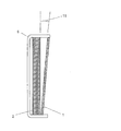
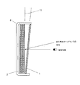
- FIG. 1 is a schematic cross-sectional view of an example of a vehicle image display function mirror according to the present invention.
- the cross section shown in FIG. 1 is a cross section obtained by cutting the mirror with a vehicle image display function in the vertical direction, including the normal line of the surface of the image display unit of the image display device in the vehicle image display function mirror.
- the half mirror 1 is inclined with respect to the surface of the image display unit of the image display device 2.
- main surface refers to the surface (front surface, back surface) of a plate-like or film-like member.
- side surface refers to a surface in the thickness direction of the member.
- the inclination angle 11 is not particularly limited, but is preferably 3 ° to 10 °, more preferably 4 ° to 6 °. In the vehicle image display function mirror having a curved mirror surface, the tilt angle 11 is more preferably 7 ° to 10 °.
- the inclination angle is an angle (acute angle) formed by the tangent at the center point of the half mirror and the surface of the image display device in a cross section cut in the vertical direction including the center of the vehicle image display function-equipped mirror.
- the vehicle-equipped mirror with an image display function is preferably inclined so that the distance between the reflective layer and the surface of the image display unit of the image display device increases as the distance from the upper portion of the half mirror increases.
- the vehicle image display function mirror is used as a room mirror (mirror installed on the top of the driver)
- the reflection direction of external light can be easily shifted from the observation direction of the driver with such a configuration.
- the inclination between the image display device and the half mirror may be variable or fixed.
- the image display device and the half mirror may be integrated with the image display device by a frame provided on the side surface of the half mirror, for example.
- the “mirror with an image display function for a vehicle” may be simply referred to as “mirror with an image display function”.
- the image display device is not particularly limited.
- the image display device is preferably an image display device that emits (emits light) linearly polarized light to form an image, and more preferably a liquid crystal display device or an organic EL device.
- the liquid crystal display device may be a transmission type or a reflection type, and is particularly preferably a transmission type.
- the liquid crystal display device includes an IPS (In Plane Switching) mode, an FFS (Fringe Field Switching) mode, a VA (Vertical Alignment) mode, an ECB (Electrically Controlled Birefringence) mode, an STN (Super Twisted Nematic) mode, and a TN (Twisted Nematic) mode.
- any liquid crystal display device such as an OCB (Optically Compensated Bend) mode may be used.
- the average visible light reflection at a wavelength of 380 nm to 780 nm is preferably 30% or more, and more preferably 40% or more.
- the reflection of visible light when the image display device is turned off may be derived from the constituent members (such as a reflective polarizing plate and a backlight unit) of the image display device.
- the image displayed on the image display unit of the image display device may be a still image, a moving image, or simply text information. Further, it may be a monochrome display such as black and white, a multi-color display, or a full-color display.
- a preferable example of the image displayed on the image display unit of the image display device is an image taken by a vehicle-mounted camera. This image is preferably a moving image.
- the image display device only needs to indicate the emission peak wavelength ⁇ R of red light, the emission peak wavelength ⁇ G of green light, and the emission peak wavelength ⁇ B of blue light in the emission spectrum during white display.
- ⁇ R may be any wavelength in the range of 580 to 700 nm, preferably 610 to 680 nm.
- ⁇ G may be any wavelength in the range of 500 to 580 nm, preferably 510 to 550 nm.
- ⁇ B may be any wavelength in the range of 400 to 500 nm, preferably in the range of 440 to 480 nm.
- the half mirror may be plate-shaped or film-shaped, and may have a curved surface.
- the half mirror may be flat or curved.
- a curved half mirror can be produced using a curved front plate.
- the half mirror includes a reflective layer.
- the half mirror may include other layers such as a front plate or an adhesive layer.
- the area of the main surface of the front plate may be larger than the area of the main surface of the reflective layer, or may be the same or smaller.
- the “main surface” refers to the surface (front surface or back surface) of a plate-like or film-like member.
- the reflective layer may be bonded to a part of the main surface of the front plate, and another type of reflective layer such as a metal foil may be bonded or formed at other portions. With such a configuration, an image can be displayed on a part of the mirror.
- a reflective layer may be bonded to the entire front plate main surface.
- a half mirror having a main surface with the same area as the image display unit of the image display device may be used, and the main surface area is larger or smaller than the image display unit of the image display device.
- a half mirror may be used. By selecting these relationships, it is possible to adjust the ratio and position of the surface of the image display unit with respect to the entire surface of the mirror.
- the film thickness of the half mirror is not particularly limited, but is preferably 100 ⁇ m to 20 mm, more preferably 200 ⁇ m to 15 mm, and even more preferably 300 ⁇ m to 10 mm.
- a reflective layer that can function as a transflective layer may be used. That is, the reflective layer functions so that an image is displayed on the front surface of the mirror with an image display function by transmitting light emitted from the image display device when displaying an image, while reflecting when not displaying an image.
- the layer may be any layer as long as it reflects at least part of incident light from the front surface direction and transmits reflected light from the image display device so that the front surface of the mirror with an image display function functions as a mirror.
- Examples of the reflective layer include a metal layer, a linearly polarized reflective layer, and a circularly polarized reflective layer.
- the metal layer preferably has a light transmittance in the visible light region of 30% to 70% and a light reflectance in the visible light region of 30% to 70%.
- the light transmittance is the total light transmittance measured using an integrating sphere light transmittance measuring device
- the light reflectance is a combination of the scattering reflectance and the regular reflectance
- the direct transmittance The specular reflectance can be measured with a spectrophotometer.
- the metal layer include a metal layer such as aluminum or silver, and a metal layer deposited on a polymer film as a support may be used. The linearly polarized light reflecting layer and the circularly polarized light reflecting layer will be described below.
- Linear polarization reflection layer examples include (i) a linearly polarized light reflecting plate having a multilayer structure, (ii) a polarizer in which thin films having different birefringence are laminated, (iii) a wire grid polarizer, (iv) a polarizing prism, (v) Examples include a scattering anisotropic polarizing plate.
- Examples of the linearly polarized light reflecting plate having a multilayer structure include those obtained by laminating a plurality of dielectric thin films having different refractive indexes. In order to obtain a wavelength selective reflection film, it is preferable to alternately stack a plurality of high-refractive-index dielectric thin films and low-refractive-index dielectric thin films.
- the number of types is not limited to two or more. It may be.
- the number of laminated layers is preferably 2 to 20 layers, more preferably 2 to 12 layers, still more preferably 4 to 10 layers, and particularly preferably 6 to 8 layers. When the number of stacked layers exceeds 20, the production efficiency may be reduced due to multilayer deposition, and the object and effect of the present invention may not be achieved.
- the order of stacking the dielectric thin films is not particularly limited and can be appropriately selected depending on the purpose. For example, when the refractive index of an adjacent film is high, a film having a lower refractive index is first stacked. . Conversely, when the refractive index of the adjacent layer is low, a film having a higher refractive index is first laminated. The boundary between high and low refractive index is 1.8. Note that whether the refractive index is high or low is not absolute. Among high-refractive-index materials, there may be a material with a relatively high refractive index and a material with a relatively low refractive index, which are used alternately. May be.
- Examples of the material for the high refractive index dielectric thin film include Sb 2 O 3 , Sb 2 S 3 , Bi 2 O 3 , CeO 2 , CeF 3 , HfO 2 , La 2 O 3 , Nd 2 O 3 , and Pr 6.
- O 11 Sc 2 O 3 , SiO, Ta 2 O 5 , TiO 2 , TlCl, Y 2 O 3 , ZnSe, ZnS, ZrO 2 and the like can be mentioned.
- Bi 2 O 3 , CeO 2 , CeF 3 , HfO 2 , SiO, Ta 2 O 5 , TiO 2 , Y 2 O 3 , ZnSe, ZnS, and ZrO 2 are preferable, and among these, SiO, Ta 2 O 5 , TiO 2 , Y 2 O 3 , ZnSe, ZnS, and ZrO 2 are particularly preferable.
- Examples of the material for the low refractive index dielectric thin film include Al 2 O 3 , BiF 3 , CaF 2 , LaF 3 , PbCl 2 , PbF 2 , LiF, MgF 2 , MgO, NdF 3 , SiO 2 , Si 2 O. 3 , NaF, ThO 2 , ThF 4 , and the like.
- Al 2 O 3 , BiF 3 , CaF 2 , MgF 2 , MgO, SiO 2 and Si 2 O 3 are preferable, and Al 2 O 3 , CaF 2 , MgF 2 , MgO, SiO 2 and Si 2 O 3 are preferable.
- the atomic ratio is not particularly limited and can be appropriately selected according to the purpose. The atomic ratio can be adjusted by changing the atmospheric gas concentration during film formation.
- the method for forming the dielectric thin film is not particularly limited and may be appropriately selected depending on the purpose.
- a vacuum vapor deposition method such as ion plating or ion beam
- a physical vapor deposition method such as sputtering ( PVD method), chemical vapor deposition method (CVD method), and the like.
- the vacuum evaporation method and the sputtering method are preferable, and the sputtering method is particularly preferable.
- a DC sputtering method having a high film formation rate is preferable. In the DC sputtering method, it is preferable to use a material having high conductivity.
- a method for forming a multilayer film by sputtering for example, (1) a one-chamber method in which films are alternately or sequentially formed from a plurality of targets in one chamber, and (2) continuous film formation in a plurality of chambers.
- a multi-chamber method there is a multi-chamber method.
- the multi-chamber method is particularly preferable from the viewpoint of preventing productivity and material contamination.
- the thickness of the dielectric thin film is preferably ⁇ / 16 to ⁇ , more preferably ⁇ / 8 to 3 ⁇ / 4, and more preferably ⁇ / 6 to 3 ⁇ / 8 in the optical wavelength order.
- the light propagating in the dielectric deposition layer is determined by the product of the thickness of the dielectric thin film and the refractive index of the film with respect to the light due to multiple reflections of part of the light for each dielectric thin film. Only light of a wavelength is selectively transmitted. Further, the central transmission wavelength of the dielectric vapor deposition layer has an angle dependency with respect to the incident light, and the transmission wavelength can be changed by changing the incident light.
- a polarizer in which thin films having different birefringence are laminated for example, those described in JP-T-9-506837 can be used.
- a polarizer when processed under conditions selected to obtain a refractive index relationship, a polarizer can be formed using a wide variety of materials.
- one of the first materials needs to have a different refractive index than the second material in the chosen direction.
- This difference in refractive index can be achieved in a variety of ways, including stretching, extrusion, or coating during or after film formation.
- Commercially available products can be used as the polarizer in which thin films having different birefringence are laminated. Examples of commercially available products include DBEF (registered trademark) (manufactured by 3M).
- a wire grid polarizer is a polarizer that transmits one of polarized light and reflects the other by birefringence of a fine metal wire.
- the wire grid polarizer is a periodic arrangement of metal wires, and is mainly used as a polarizer in the terahertz wave band. In order for the wire grid to function as a polarizer, the wire interval needs to be sufficiently smaller than the wavelength of the incident electromagnetic wave.
- metal wires are arranged at equal intervals. The polarization component in the polarization direction parallel to the longitudinal direction of the metal wire is reflected by the wire grid polarizer, and the polarization component in the perpendicular polarization direction is transmitted through the wire grid polarizer.
- wire grid polarizer a commercially available product can be used, and examples of the commercially available product include a wire grid polarizing filter 50 ⁇ 50, NT46-636 manufactured by Edmund Optics.
- the circularly polarized light reflecting layer examples include a circularly polarized light reflecting layer including a linearly polarized light reflecting plate and a quarter wavelength plate and a circularly polarized light reflecting layer including a cholesteric liquid crystal layer (hereinafter, for the sake of distinction, “Pol ⁇ / 4 Circular polarization reflective layer “and” cholesteric circular polarization reflection layer ").
- the linearly polarized light reflecting plate and the quarter wave plate are arranged such that the slow axis of the quarter wave plate is 45 ° with respect to the polarizing reflection axis of the linearly polarized light reflecting plate. Just do it.
- the quarter wave plate and the linearly polarized light reflecting plate may be bonded by, for example, an adhesive layer.
- the quarter-wave plate and the circularly polarized light reflecting layer are preferably laminated with the same main surface area.
- the Pol ⁇ / 4 circularly polarized light reflecting layer By using the Pol ⁇ / 4 circularly polarized light reflecting layer so that the linearly polarized light reflector is close to the image display device, the light for image display from the image display device can be efficiently converted into circularly polarized light. Thus, the light can be emitted from the front surface of the mirror with an image display function.
- the polarization reflection axis of the linearly polarized light reflecting plate may be adjusted so as to transmit this linearly polarized light.
- the film thickness of the Pol ⁇ / 4 circularly polarized light reflecting layer is preferably in the range of 2.0 ⁇ m to 300 ⁇ m, more preferably in the range of 8.0 ⁇ m to 200 ⁇ m.
- the linearly polarized light reflecting plate those described above as the linearly polarized light reflecting layer can be used.
- the quarter wavelength plate a quarter wavelength plate described later can be used.
- the cholesteric circularly polarized light reflection layer includes at least one cholesteric liquid crystal layer.
- the cholesteric liquid crystal layer included in the cholesteric circularly polarized light reflection layer may be any layer that exhibits selective reflection in the visible light region.
- the circularly polarized light reflecting layer may include two or more cholesteric liquid crystal layers, and may include other layers such as an alignment layer.
- the circularly polarized light reflecting layer is preferably composed only of a cholesteric liquid crystal layer. Further, when the circularly polarized light reflection layer includes a plurality of cholesteric liquid crystal layers, it is preferable that they are in direct contact with adjacent cholesteric liquid crystal layers.
- the circularly polarized light reflection layer preferably includes three or more cholesteric liquid crystal layers such as three layers and four layers.
- the film thickness of the cholesteric circularly polarized light reflecting layer is preferably in the range of 2.0 ⁇ m to 300 ⁇ m, more preferably in the range of 8.0 ⁇ m to 200 ⁇ m.
- a cholesteric liquid crystal layer means a layer in which a cholesteric liquid crystal phase is fixed.
- the cholesteric liquid crystal layer is sometimes simply referred to as a liquid crystal layer.
- the cholesteric liquid crystal phase selectively reflects circularly polarized light of either right circularly polarized light or left circularly polarized light in a specific wavelength region and selectively transmits circularly polarized light of the other sense. It is known to show.
- the circularly polarized light selective reflection is sometimes simply referred to as selective reflection.
- the cholesteric liquid crystal layer may be a layer in which the orientation of the liquid crystal compound in the cholesteric liquid crystal phase is maintained.
- the polymerizable liquid crystal compound is placed in the orientation state of the cholesteric liquid crystal phase and then irradiated with ultraviolet rays.
- Any layer may be used as long as it is polymerized and cured by heating or the like to form a layer having no fluidity, and at the same time, the layer is changed to a state in which the orientation is not changed by an external field or an external force.
- the polymerizable liquid crystal compound may have a high molecular weight due to a curing reaction and may no longer have liquid crystallinity.
- the selective reflection center wavelength and the half width of the cholesteric liquid crystal layer can be obtained as follows. When the transmission spectrum of the light reflection layer (measured from the normal direction of the cholesteric liquid crystal layer) is measured using a spectrophotometer UV3150 (Shimadzu Corporation), a peak of reduced transmittance is observed in the selective reflection region.
- the wavelength value on the short wave side is ⁇ 1 (nm) and the wavelength value on the long wave side is ⁇ 2 (nm).
- the center wavelength ⁇ of selective reflection possessed by the cholesteric liquid crystal layer, obtained as described above, usually coincides with the wavelength at the center of gravity of the reflection peak of the circularly polarized reflection spectrum measured from the normal direction of the cholesteric liquid crystal layer.
- the center wavelength of selective reflection means the center wavelength when measured from the normal direction of the cholesteric liquid crystal layer.
- the center wavelength of selective reflection can be adjusted by adjusting the pitch of the helical structure.
- the center wavelength ⁇ can be adjusted in order to selectively reflect either the right circularly polarized light or the left circularly polarized light with respect to light of a desired wavelength by adjusting the n value and the P value.
- n ⁇ P the center wavelength of selective reflection when a light beam passes at an angle of ⁇ 2 with respect to the normal direction of the cholesteric liquid crystal layer (helical axis direction of the cholesteric liquid crystal layer) is ⁇ d .
- ⁇ d n 2 ⁇ P ⁇ cos ⁇ 2
- the center wavelength of selective reflection of the cholesteric liquid crystal layer included in the circularly polarized light reflecting layer it is possible to prevent the visibility of the image from being viewed obliquely. Also, the visibility of the image from an oblique direction can be intentionally reduced. This is useful because, for example, it is possible to prevent peeping in a smartphone or a personal computer.
- the mirror with an image display function of the present invention may appear in the image and the mirror reflection image viewed from an oblique direction. By including a cholesteric liquid crystal layer having a central wavelength of selective reflection in the infrared light region in the circularly polarized light reflecting layer, it is possible to prevent such a color.
- the center wavelength of selective reflection in the infrared region is specifically 780 to 900 nm, preferably 780 to 850 nm.
- the cholesteric liquid crystal layer has a selective reflection central wavelength in the visible light region, and is most on the image display device side. .
- the pitch of the cholesteric liquid crystal phase depends on the type of chiral agent used together with the polymerizable liquid crystal compound or the concentration of the chiral agent, a desired pitch can be obtained by adjusting these.
- a desired pitch can be obtained by adjusting these.
- the circularly polarized light reflection layer includes a cholesteric liquid crystal layer having a central wavelength of selective reflection in the wavelength range of red light and a cholesteric liquid crystal layer having a central wavelength of selective reflection in the wavelength range of green light. And a cholesteric liquid crystal layer having a center wavelength of selective reflection in the wavelength range of blue light.
- the reflective layer is, for example, a cholesteric liquid crystal layer having a central wavelength of selective reflection in 400 nm to 500 nm, a cholesteric liquid crystal layer having a central wavelength of selective reflection in 500 nm to 580 nm, and a cholesteric liquid crystal having a central wavelength of selective reflection in 580 nm to 700 nm. It is preferable to include a layer.
- the circularly polarized light reflecting layer includes a plurality of cholesteric liquid crystal layers
- the cholesteric liquid crystal layer closer to the image display device has a longer selective reflection center wavelength.
- the center wavelength of selective reflection that each cholesteric liquid crystal layer has is 5 nm or more with the wavelength of the emission peak of the image display device. It is preferable to make them different. This difference is more preferably 10 nm or more.
- the wavelength of the emission peak of the image display device can be confirmed by the emission spectrum when the image display device displays white.
- the peak wavelength may be any peak wavelength in the visible light region of the emission spectrum.
- the above-described red light emission peak wavelength ⁇ R, green light emission peak wavelength ⁇ G, and blue light emission peak wavelength ⁇ B of the image display device Any one or more selected from the group consisting of:
- the central wavelength of selective reflection of the cholesteric liquid crystal layer is 5 nm or more for any of the above-described red light emission peak wavelength ⁇ R, green light emission peak wavelength ⁇ G, and blue light emission peak wavelength ⁇ B of the image display device, preferably It is preferably different by 10 nm or more.
- the central wavelength of selective reflection of all the cholesteric liquid crystal layers is different from the wavelength of the peak of light emitted from the image display device by 5 nm or more, preferably 10 nm or more. do it.
- the image display device is a full-color display device showing an emission peak wavelength ⁇ R of red light, an emission peak wavelength ⁇ G of green light, and an emission peak wavelength ⁇ B of blue light in the emission spectrum during white display
- All of the central wavelengths of selective reflection of the cholesteric liquid crystal layer may be different from each of ⁇ R, ⁇ G, and ⁇ B by 5 nm or more, preferably 10 nm or more.
- the central wavelength of selective reflection of the cholesteric liquid crystal layer By adjusting the central wavelength of selective reflection of the cholesteric liquid crystal layer to be used according to the emission wavelength range of the image display device and the usage mode of the circularly polarized light reflection layer, a bright image can be displayed with high light utilization efficiency.
- the usage of the circularly polarized light reflecting layer include an incident angle of light to the circularly polarized light reflecting layer, an image observation direction, and the like.
- each cholesteric liquid crystal layer a cholesteric liquid crystal layer whose spiral sense is either right or left is used.
- the sense of reflected circularly polarized light in the cholesteric liquid crystal layer coincides with the sense of a spiral.
- the spiral senses of the plurality of cholesteric liquid crystal layers may all be the same or different. That is, either the right or left sense cholesteric liquid crystal layer may be included, or both the right and left sense cholesteric liquid crystal layers may be included.
- the spiral senses of the plurality of cholesteric liquid crystal layers are all the same.
- the spiral sense at that time may be determined according to the sense of circularly polarized light of the sense obtained as each cholesteric liquid crystal layer emitted from the image display device and transmitted through the quarter-wave plate. Specifically, a cholesteric liquid crystal layer having a spiral sense that transmits the circularly polarized light of the sense obtained from the image display device and transmitted through the quarter wavelength plate may be used.
- ⁇ n can be adjusted by adjusting the kind of the polymerizable liquid crystal compound and the mixing ratio thereof, or by controlling the temperature at the time of fixing the alignment.
- a plurality of cholesteric liquid crystal layers having the same pitch P and the same spiral sense may be stacked. By laminating cholesteric liquid crystal layers having the same pitch P and the same spiral sense, the circularly polarized light selectivity can be increased at a specific wavelength.
- the mirror with an image display function using the cholesteric circularly polarized light reflection layer may further include a quarter wavelength plate.
- a quarter-wave plate between the image display device and the cholesteric circularly polarized light reflection layer in particular, the light from the image display device displaying an image by linearly polarized light is converted into circularly polarized light, and the cholesteric circularly polarized light is converted. It is possible to make the light incident on the reflective layer. Therefore, the light reflected by the circularly polarized light reflection layer and returning to the image display device side can be greatly reduced, and a bright image can be displayed.
- the cholesteric circularly polarized light reflecting layer can be configured not to generate sense circularly polarized light reflected to the image display device side by using a quarter wavelength plate, it causes multiple reflection between the image display device and the half mirror. It is difficult for image display quality to deteriorate. That is, for example, the center wavelength of selective reflection of the cholesteric liquid crystal layer included in the cholesteric circularly polarizing reflection layer is substantially the same as the emission peak wavelength of blue light in the emission spectrum during white display of the image display device (for example, the difference is less than 5 nm). Even if it is, it can transmit the emitted light of an image display apparatus to the front side, without producing the circularly polarized light of the sense reflected in an image display side in a circularly polarized light reflection layer.
- the quarter-wave plate used in combination with the cholesteric circularly polarized reflective layer is preferably angle-adjusted so that the image is brightest when bonded to the image display device. That is, the relationship between the polarization direction of the linearly polarized light (transmission axis) and the slow axis of the quarter-wave plate so that the linearly polarized light is transmitted best, particularly for an image display device displaying an image by linearly polarized light. Is preferably adjusted. For example, in the case of a single layer type quarter wave plate, it is preferable that the transmission axis and the slow axis form an angle of 45 °.
- the light emitted from the image display device displaying an image by linearly polarized light is circularly polarized light of either right or left sense after passing through the quarter wavelength plate.
- the circularly polarized light reflecting layer may be formed of a cholesteric liquid crystal layer having a twist direction that transmits the circularly polarized light having the above-described sense.
- the quarter wave plate may be a retardation layer that functions as a quarter wave plate in the visible light region.
- the quarter-wave plate include a single-layer quarter-wave plate, a broadband quarter-wave plate in which a quarter-wave plate and a half-wave retardation plate are stacked, and the like.
- the front phase difference of the former 1 ⁇ 4 wavelength plate may be a length that is 1 ⁇ 4 of the emission wavelength of the image display device. Therefore, for example, when the emission wavelength of the image display device is 450 nm, 530 nm, and 640 nm, the wavelength of 450 nm is 112.5 nm ⁇ 10 nm, preferably 112.5 nm ⁇ 5 nm, more preferably 112.5 nm, and 530 nm.
- Reverse dispersion such that the phase difference is 160 nm ⁇ 10 nm, preferably 160 nm ⁇ 5 nm, more preferably 160 nm at a wavelength of 5 nm ⁇ 10 nm, preferably 132.5 nm ⁇ 5 nm, more preferably 132.5 nm, 640 nm
- the retardation layer is most preferable as a quarter wavelength plate, but a retardation plate having a small retardation wavelength dispersion or a forward dispersion retardation plate can also be used.
- the reverse dispersion means a property that the absolute value of the phase difference becomes larger as the wavelength becomes longer, and the forward dispersion means a property that the absolute value of the phase difference becomes larger as the wavelength becomes shorter.
- the laminated quarter-wave plate is formed by laminating a quarter-wave plate and a half-wave retardation plate at an angle of 60 ° with the slow axis, and the side of the half-wave retardation plate is linearly polarized. It is arranged on the incident side and the slow axis of the half-wave retardation plate is used so as to cross 15 ° or 75 ° with respect to the polarization plane of the incident linearly polarized light. Can be suitably used because of its good resistance.
- quartz plate stretched polycarbonate film, stretched norbornene-based polymer film, transparent film containing inorganic particles having birefringence such as strontium carbonate, and oblique deposition of inorganic dielectric on support Thin films and the like.
- the quarter-wave plate examples include (1) a birefringent film having a large retardation and a birefringence having a small retardation described in JP-A-5-27118 and JP-A-5-27119.
- a retardation plate capable of achieving a quarter wavelength in a wide wavelength region by laminating two polymer films, as described in (4) WO 00/26705 pamphlet A retardation plate capable of achieving a quarter wavelength in a wide wavelength region using the modified polycarbonate film described in (5), (5) a wide wavelength region using a cellulose acetate film described in International Publication No. 00/65384 pamphlet And a retardation plate capable of achieving a quarter wavelength.
- a commercial item can also be used as a quarter wavelength plate, As a commercial item, Pure Ace (trademark) WR (Teijin Ltd. polycarbonate film) etc. are mentioned, for example.
- the quarter wavelength plate may be formed by arranging and fixing a polymerizable liquid crystal compound or a polymer liquid crystal compound.
- a liquid crystal composition is applied to the surface of a temporary support, an alignment film, or a front plate, and a polymerizable liquid crystal compound in the liquid crystal composition is formed into a nematic alignment in a liquid crystal state, and then photocrosslinked. It can be formed by immobilization by thermal crosslinking. Details of the liquid crystal composition or the production method will be described later.
- a quarter-wave plate is formed by applying a liquid crystal composition on a surface of a temporary support, an alignment film, or a front plate to form a nematic alignment in a liquid crystal state and then cooling the composition containing a polymer liquid crystal compound. It may be a layer obtained by immobilizing.
- the quarter-wave plate may be bonded to the cholesteric circularly polarized light reflecting layer by an adhesive layer or may be in direct contact, but the latter is preferred.
- a preparation material and a preparation method of a quarter-wave plate formed from a cholesteric liquid crystal layer and a liquid crystal composition will be described.
- the material used for forming the quarter wavelength plate include a liquid crystal composition containing a polymerizable liquid crystal compound.
- the material used for forming the cholesteric liquid crystal layer include a liquid crystal composition containing a chiral agent (optically active compound).
- liquid crystal composition which is further mixed with a surfactant or polymerization initiator and dissolved in a solvent, to a temporary support, a support, an alignment film, a lower cholesteric liquid crystal layer, and the like. After aging, the liquid crystal composition can be fixed by curing to form a cholesteric liquid crystal layer or a quarter-wave plate.
- a rod-like liquid crystal compound may be used as the polymerizable liquid crystal compound.
- the rod-like polymerizable liquid crystal compound include a rod-like nematic liquid crystal compound.
- rod-like nematic liquid crystal compounds include azomethines, azoxys, cyanobiphenyls, cyanophenyl esters, benzoic acid esters, cyclohexanecarboxylic acid phenyl esters, cyanophenylcyclohexanes, cyano-substituted phenylpyrimidines, alkoxy-substituted phenylpyrimidines.
- Phenyldioxanes, tolanes and alkenylcyclohexylbenzonitriles are preferably used. Not only low-molecular liquid crystal compounds but also high-molecular liquid crystal compounds can be used.
- the polymerizable liquid crystal compound can be obtained by introducing a polymerizable group into the liquid crystal compound.
- the polymerizable group include an unsaturated polymerizable group, an epoxy group, and an aziridinyl group, preferably an unsaturated polymerizable group, and particularly preferably an ethylenically unsaturated polymerizable group.
- the polymerizable group can be introduced into the molecule of the liquid crystal compound by various methods.
- the number of polymerizable groups possessed by the polymerizable liquid crystal compound is preferably 1 to 6, more preferably 1 to 3. Examples of polymerizable liquid crystal compounds are described in Makromol. Chem. 190, 2255 (1989), Advanced Materials 5, 107 (1993), US Pat. No.
- the addition amount of the polymerizable liquid crystal compound in the liquid crystal composition is preferably 80 to 99.9% by mass with respect to the solid content mass (mass excluding the solvent) of the liquid crystal composition, and is preferably 85 to 99. It is more preferably 5% by mass, particularly preferably 90 to 99% by mass.
- -Chiral agents optically active compounds-
- the material used for forming the cholesteric liquid crystal layer preferably contains a chiral agent.
- the chiral agent has a function of inducing a helical structure of a cholesteric liquid crystal phase.
- the chiral compound may be selected according to the purpose because the helical sense or helical pitch induced by the compound is different. There is no restriction
- Examples of chiral agents include liquid crystal device handbook (Chapter 3, Section 4-3, TN, chiral agent for STN, 199 pages, edited by Japan Society for the Promotion of Science, 142th Committee, 1989), JP-A 2003-287623, Examples thereof include compounds described in JP-A No. 2002-302487, JP-A No. 2002-80478, JP-A No. 2002-80851, JP-A No. 2010-181852 or JP-A No. 2014-034581.
- a chiral agent generally contains an asymmetric carbon atom, but an axially asymmetric compound or a planar asymmetric compound containing no asymmetric carbon atom can also be used as the chiral agent.
- the axial asymmetric compound or the planar asymmetric compound include binaphthyl, helicene, paracyclophane, and derivatives thereof.
- the chiral agent may have a polymerizable group. When both the chiral agent and the liquid crystal compound have a polymerizable group, they are derived from the repeating unit derived from the polymerizable liquid crystal compound and the chiral agent by a polymerization reaction between the polymerizable chiral agent and the polymerizable liquid crystal compound.
- the polymerizable group possessed by the polymerizable chiral agent is preferably the same group as the polymerizable group possessed by the polymerizable liquid crystal compound. Therefore, the polymerizable group of the chiral agent is also preferably an unsaturated polymerizable group, an epoxy group or an aziridinyl group, more preferably an unsaturated polymerizable group, and an ethylenically unsaturated polymerizable group. Particularly preferred.
- the chiral agent may be a liquid crystal compound.
- an isosorbide derivative, an isomannide derivative, or a binaphthyl derivative can be preferably used.
- the isosorbide derivative a commercial product such as LC-756 manufactured by BASF may be used.
- the content of the chiral agent in the liquid crystal composition is preferably from 0.01 mol% to 200 mol%, more preferably from 1.0 mol% to 30 mol%, based on the total molar amount of the polymerizable liquid crystal compound.
- the liquid crystal composition preferably contains a polymerization initiator.
- the polymerization initiator to be used is preferably a photopolymerization initiator that can start the polymerization reaction by ultraviolet irradiation.
- photopolymerization initiators include ⁇ -carbonyl compounds (described in US Pat. Nos. 2,367,661 and 2,367,670), acyloin ether (described in US Pat. No. 2,448,828), ⁇ -hydrocarbon substituted aromatics.
- Group acyloin compounds described in US Pat. No. 2,722,512
- polynuclear quinone compounds described in US Pat.
- acyl phosphine oxide compound As the polymerization initiator, it is also preferable to use an acyl phosphine oxide compound or an oxime compound.
- acylphosphine oxide compound for example, IRGACURE819 (compound name: bis (2,4,6-trimethylbenzoyl) -phenylphosphine oxide) manufactured by BASF Japan Ltd. can be used.
- oxime compounds examples include IRGACURE OXE01 (manufactured by BASF), IRGACURE OXE02 (manufactured by BASF), TR-PBG-304 (manufactured by Changzhou Strong Electronic New Materials Co., Ltd.), Adeka Arcles NCI-831, Adeka Arcles NCI-930 Commercial products such as (ADEKA) and Adeka Arcles NCI-831 (ADEKA) can be used. Only one type of polymerization initiator may be used, or two or more types may be used in combination.
- the content of the photopolymerization initiator in the liquid crystal composition is preferably 0.1 to 20% by mass and preferably 0.5% to 5.0% by mass with respect to the content of the polymerizable liquid crystal compound. More preferably.
- the liquid crystal composition may optionally contain a crosslinking agent in order to improve the film strength after curing and improve the durability.
- a crosslinking agent one that can be cured by ultraviolet rays, heat, moisture, or the like can be suitably used.
- polyfunctional acrylate compounds such as a trimethylol propane tri (meth) acrylate and pentaerythritol tri (meth) acrylate
- Glycidyl (meth) acrylate Epoxy compounds such as ethylene glycol diglycidyl ether; aziridine compounds such as 2,2-bishydroxymethylbutanol-tris [3- (1-aziridinyl) propionate], 4,4-bis (ethyleneiminocarbonylamino) diphenylmethane; hexa Isocyanate compounds such as methylene diisocyanate and biuret type isocyanate; polyoxazoline compounds having an oxazoline group in the side chain; vinyltrimethoxysilane, N- (2-aminoethyl) 3-aminopropylto Alkoxysilane compounds such as methoxy silane.
- a well-known catalyst can be used according to the reactivity of a crosslinking agent, and productivity can be improved in addition to membrane strength and durability improvement. These may be used individually by 1 type and may use 2 or more types together.
- the content of the crosslinking agent is preferably 3.0% by mass to 20% by mass, and more preferably 5.0% by mass to 15% by mass. When the content of the crosslinking agent is 3.0% by mass or more, an effect of improving the crosslinking density can be obtained. Moreover, the stability of the layer formed can be maintained by setting it as 20 mass% or less.
- an alignment control agent that contributes to stable or rapid planar alignment may be added.
- the alignment control agent include fluorine (meth) acrylate polymers described in paragraphs [0018] to [0043] of JP-A-2007-272185, and paragraphs [0031] to [0034] of JP-A-2012-203237. And compounds represented by the formulas (I) to (IV) as described above.
- 1 type may be used independently and 2 or more types may be used together.
- the addition amount of the alignment control agent in the liquid crystal composition is preferably 0.01% by mass to 10% by mass and more preferably 0.01% by mass to 5.0% by mass with respect to the total mass of the polymerizable liquid crystal compound. 0.02% by mass to 1.0% by mass is particularly preferable.
- the liquid crystal composition may contain at least one selected from a surfactant for adjusting the surface tension of the coating film to make the film thickness uniform, and various additives such as a polymerizable monomer.
- a polymerization inhibitor, an antioxidant, an ultraviolet absorber, a light stabilizer, a colorant, metal oxide fine particles, and the like may be added as long as the optical performance is not deteriorated. Can be added.
- organic solvent is used preferably.
- the organic solvent is not particularly limited and may be appropriately selected depending on the intended purpose. For example, ketones, alkyl halides, amides, sulfoxides, heterocyclic compounds, hydrocarbons, esters, ethers, etc. Is mentioned. These may be used individually by 1 type and may use 2 or more types together. Among these, ketones are particularly preferable in consideration of environmental load.
- the method for applying the liquid crystal composition to the temporary support, the alignment film, the quarter wavelength plate, the underlying cholesteric liquid crystal layer, and the like is not particularly limited and can be appropriately selected according to the purpose.
- the coating method include curtain coating method, extrusion coating method, direct gravure coating method, reverse gravure coating method, die coating method, spin coating method, dip coating method, spray coating method, and slide coating method. It can also be carried out by transferring a liquid crystal composition separately coated on a support. The liquid crystal molecules are aligned by heating the applied liquid crystal composition.
- cholesteric alignment may be performed, and in forming the quarter-wave plate, nematic alignment is preferable.
- the heating temperature is preferably 200 ° C. or lower, and more preferably 130 ° C. or lower.
- the heating temperature is preferably 50 ° C. to 120 ° C., more preferably 60 ° C. to 100 ° C.
- the aligned liquid crystal compound can be further polymerized to cure the liquid crystal composition.
- the polymerization may be either thermal polymerization or photopolymerization utilizing light irradiation, but photopolymerization is preferred. It is preferable to use ultraviolet rays for light irradiation.
- the irradiation energy is preferably 20mJ / cm 2 ⁇ 50J / cm 2, 100mJ / cm 2 ⁇ 1,500mJ / cm 2 is more preferable.
- light irradiation may be performed under heating conditions or in a nitrogen atmosphere.
- the irradiation ultraviolet wavelength is preferably 350 nm to 430 nm.
- the polymerization reaction rate is preferably high from the viewpoint of stability, preferably 70% or more, and more preferably 80% or more.
- the polymerization reaction rate can be determined by measuring the consumption ratio of the polymerizable functional group using an IR absorption spectrum.
- each cholesteric liquid crystal layer is not particularly limited as long as it exhibits the above characteristics, but is preferably in the range of 1.0 to 150 ⁇ m, more preferably in the range of 4.0 to 100 ⁇ m.
- the thickness of the quarter-wave plate formed from the liquid crystal composition is not particularly limited, but is preferably 0.2 to 10 ⁇ m, more preferably 0.5 to 2.0 ⁇ m.
- the liquid crystal composition may be applied and layered on the surface of the temporary support or the alignment layer formed on the surface of the temporary support.
- the temporary support or the temporary support and the alignment layer may be peeled off after forming the layer.
- a support may be used particularly when forming a quarter wavelength plate. The support does not have to be peeled off after forming the layer.
- the temporary support and the support include polyester such as polyethylene terephthalate (PET), polycarbonate, acrylic resin, epoxy resin, polyurethane, polyamide, polyolefin, cellulose derivative, silicone, or glass plate.
- PET polyethylene terephthalate
- the temporary support body should just be peeled, for example after adhere
- the temporary support may function as a protective film after the circularly polarized reflective layer is bonded to the front plate and further until the circularly polarized reflective layer is bonded to the image display device.
- the alignment layer has a rubbing treatment of organic compounds such as polymers (resins such as polyimide, polyvinyl alcohol, polyester, polyarylate, polyamideimide, polyetherimide, polyamide, modified polyamide), oblique deposition of inorganic compounds, and microgrooves. It can be provided by means such as formation of a layer or accumulation of an organic compound (for example, ⁇ -tricosanoic acid, dioctadecylmethylammonium chloride, methyl stearylate) using the Langmuir-Blodgett method (LB film). Further, an alignment layer that generates an alignment function by application of an electric field, application of a magnetic field, or light irradiation may be used.
- organic compounds such as polymers (resins such as polyimide, polyvinyl alcohol, polyester, polyarylate, polyamideimide, polyetherimide, polyamide, modified polyamide), oblique deposition of inorganic compounds, and microgrooves.
- the alignment layer made of a polymer is preferably subjected to a rubbing treatment and then a liquid crystal composition is applied to the rubbing treatment surface.
- the rubbing treatment can be performed by rubbing the surface of the polymer layer with paper or cloth in a certain direction.
- the liquid crystal composition may be applied to the surface of the temporary support without providing the alignment layer, or the surface obtained by rubbing the temporary support.
- the thickness of the alignment layer is preferably from 0.01 to 5 ⁇ m, more preferably from 0.05 to 2.0 ⁇ m.
- -Laminated film of layers formed from polymerizable liquid crystal compounds When forming a multi-layer film composed of a plurality of cholesteric liquid crystal layers and a multi-layer film composed of a quarter-wave plate and a plurality of cholesteric liquid crystal layers, each is directly applied to the surface of the quarter-wave plate or the previous cholesteric liquid crystal layer.
- the liquid crystal composition containing a polymerizable liquid crystal compound or the like may be applied, and the steps of alignment and fixing may be repeated.
- a separately prepared quarter wave plate, cholesteric liquid crystal layer, or a laminate thereof is used with an adhesive or the like. However, the former is preferable.
- the adhesive layer is laminated without using the adhesive layer. It is.
- the liquid crystal on the air interface side of the cholesteric liquid crystal layer formed earlier is formed by forming the next cholesteric liquid crystal layer so as to be in direct contact with the surface of the cholesteric liquid crystal layer formed earlier. This is because the orientation direction of the molecules matches the orientation direction of the liquid crystal molecules below the cholesteric liquid crystal layer formed thereon, and the polarization property of the laminate of the cholesteric liquid crystal layer is improved.
- the mirror with an image display function of the present invention may have a front plate.
- the front plate may be flat or curved.
- the front plate may be in direct contact with the reflective layer, or may be directly adhered by an adhesive layer or the like.
- the front plate is not particularly limited.
- As the front plate a glass plate or a plastic film used for producing a normal mirror can be used.
- the front plate is preferably transparent in the visible light region.
- “transparent in the visible light region” means that the light transmittance in the visible light region is 80% or more, preferably 85% or more.
- the light transmittance used as a measure of transparency is measured by measuring the total light transmittance and the amount of scattered light using the method described in JIS-K7105, that is, using an integrating sphere light transmittance measuring device. It can be calculated by subtracting the rate.
- the front plate preferably has a small birefringence.
- the front phase difference may be 20 nm or less, preferably less than 10 nm, and more preferably 5 nm or less.
- the plastic film include polyester such as polyethylene terephthalate (PET), polycarbonate, acrylic resin, epoxy resin, polyurethane, polyamide, polyolefin, cellulose derivative, and silicone.
- the curved front plate can be produced by a plastic processing method such as injection molding.
- a resin product can be obtained by melting raw plastic pellets with heat, injecting them into a mold, and then cooling and solidifying.
- the film thickness of the front plate may be about 100 ⁇ m to 10 mm, preferably 200 ⁇ m to 5.0 mm, more preferably 500 ⁇ m to 2.0 mm, and still more preferably 500 ⁇ m to 1000 ⁇ m.
- the mirror with an image display function of the present invention may include a reflective layer and a front plate, an image display device and a reflective layer, a quarter-wave plate and a linearly polarized light reflector, and other adhesive layers for bonding the layers.
- the adhesive layer may be formed from an adhesive.
- Adhesives include hot melt type, thermosetting type, photocuring type, reactive curing type, and pressure-sensitive adhesive type that does not require curing, from the viewpoint of curing method, and the materials are acrylate, urethane, urethane acrylate, epoxy , Epoxy acrylate, polyolefin, modified olefin, polypropylene, ethylene vinyl alcohol, vinyl chloride, chloroprene rubber, cyanoacrylate, polyamide, polyimide, polystyrene, polyvinyl butyral, etc. can do.
- the photocuring type is preferable as the curing method, and from the viewpoint of optical transparency and heat resistance, it is preferable to use an acrylate, urethane acrylate, epoxy acrylate, or the like material.
- the half mirror having the front plate may be produced by forming a reflective layer on the front plate, or may be produced by adhering a separately produced reflective layer to the front plate.
- the cholesteric circularly polarized light reflecting layer formed on the temporary support, or a quarter wavelength plate and a cholesteric circularly polarized light reflecting layer may be transferred to the front plate.
- a cholesteric liquid crystal layer or a laminate of cholesteric liquid crystal layers is formed on a temporary support to form a cholesteric circularly polarized light reflecting layer, which is adhered to the front plate on the surface of this circularly polarized light reflecting layer, and then if necessary
- the temporary support can be peeled off to obtain a half mirror.
- a quarter-wave plate and a cholesteric liquid crystal layer are sequentially formed on the temporary support to form a laminate of the quarter-wave plate and the cholesteric circularly polarizing reflection layer, and this cholesteric liquid crystal (circularly polarizing reflective layer) is formed. ) Can be adhered to the front plate, and then the temporary support can be peeled off as necessary to obtain a half mirror.
- the mirror with an image display function of the present invention is manufactured by arranging a half mirror including a reflective layer so that the half mirror including the reflective layer is inclined with respect to the surface of the image display unit of the image display device.
- the half mirror has a front plate
- the image display device, the reflective layer, and the front plate are arranged in this order. Thereafter, the image display device and the half mirror may be integrated as necessary.
- the manufacturing method of the mirror with an image display function may include a step of determining the tilt angle.
- the integration of the image display device and the half mirror may be performed by connection with an outer frame or a hinge or adhesion.
- Coating liquid for forming cholesteric liquid crystal layer Compound 1, compound 2, fluorine-based horizontal alignment agent 1, fluorine-based horizontal alignment agent 2, chiral agent, polymerization initiator, and solvent methyl ethyl ketone were mixed to prepare a coating solution having the following composition.
- Coating solutions 1 to 3 were prepared by adjusting the prescription amount of the chiral agent LC-756 having the above coating solution composition. Using each coating solution, a single layer of cholesteric liquid crystal layer was prepared on the temporary support in the same manner as in the preparation of the following circularly polarized reflective layer, and the reflection characteristics were confirmed. It was a circularly polarized light reflection layer, and the central reflection wavelength was as shown in Table 1 below.
- ⁇ Preparation of curved mirror front plate> The mold (upper and lower molds) was heated to 100 ° C., and polycarbonate (Panlite AD-5503 manufactured by Teijin Limited) heated to 310 ° C. was injected into the space between the upper and lower molds.
- the front plate for a curved mirror which was fixed for 1 minute, had a vertical width of 65 mm, a horizontal width of 260 mm, and a film thickness of 3.0 mm and was curved with a radius of curvature of 2000 mm on both the long side and the short side, was obtained.
- a Pol ⁇ / 4 circularly polarized light reflecting layer was prepared by the following procedure.
- a linearly polarized light reflecting plate was prepared based on the method described in JP-T-9-506837.
- 2,6-polyethylene naphthalate (PEN) and naphthalate 70 / terephthalate 30 copolyester (coPEN) were synthesized in a standard polyester resin synthesis kettle using ethylene glycol as the diol.
- a single layer film of PEN and coPEN was extruded and then stretched at a stretch ratio of 5: 1 at about 150 ° C.
- the refractive index of PEN with respect to the orientation axis was about 1.88
- the refractive index with respect to the transverse axis was 1.64
- the refractive index of the coPEN film was about 1.64.
- the thickness of the alternating layer of PEN and coPEN was formed in the film thickness shown in Table 2 (1) by co-extrusion using a 50 slot supply block supplied with a standard extrusion die.
- the PEN and coPEN layers shown in Tables 2 (2) to (5) were formed in order, and the formation of the layers (1) to (5) was repeated to make a total of 250 layers each. Laminated. Thereafter, the stretched film was heat-cured at about 230 ° C. for 30 seconds in an air oven to obtain a linearly polarized light reflector (polarization control wavelength region of 400 nm to 650 nm).
- Pure quarter (registered trademark) WR manufactured by Teijin Ltd. was used as the quarter wavelength plate.
- a linearly polarized light reflector, a quarter-wave plate, and a front plate are arranged in this order on a UV curable adhesive Exp.
- a half mirror of the example was manufactured by adhering to an adjacent layer using an adhesive of U12034-6.
- the front plate was a glass plate (vertical width 65 mm ⁇ length 260 mm, thickness 3 mm), and in the case of a curved mirror, the curved mirror front plate was used.
- a linearly polarized light reflection plate and a quarter wavelength plate were bonded to the concave curved surface side.
- the quarter-wave plate was arranged so that the slow axis of the quarter-wave plate was inclined by 45 ° with respect to the transmission axis of the linearly polarized light reflecting plate (the polarization direction of light emission of the LCD).
- the obtained half mirror is disposed on the surface of the image display unit of a liquid crystal display (LCD) (manufactured by Apple, iPad (registered trademark) Air), the linearly polarized light reflection plate faces the surface of the image display unit, and The face plate was the opposite side (front side).
- the transmission axis of the linearly polarized light reflector and the transmission axis of the LCD were arranged to be the same.
- the half mirror was integrated with the LCD at an inclination angle as shown in Table 3 to obtain a mirror with an image display function.
- UV irradiation was performed for 6 seconds to fix the cholesteric liquid crystal phase to obtain a cholesteric liquid crystal layer having a thickness of 3.5 ⁇ m.
- the same steps were repeated, and a laminate A (coating liquid 2 of the quarter-wave plate and the three cholesteric liquid crystal layers was used.
- Adhesive LCR0631 manufactured by Toagosei Co., Ltd. was applied to the surface of the cholesteric liquid crystal layer of the laminate A with a wire bar, and then adhered to a glass plate using a laminator. At this time, the count of the wire bar and the nip roll pressure of the laminator were adjusted, and the thickness of the adhesive layer was adjusted to 2 ⁇ m. After that, after placing on a hot plate at 50 ° C. and irradiating with UV for 30 seconds with an electrodeless lamp “D bulb” (60 mW / cm 2 ) manufactured by Fusion UV Systems, the PET film was peeled off, I got a half mirror.
- an electrodeless lamp “D bulb” 60 mW / cm 2
- the obtained half mirror is disposed on the image display unit surface of a liquid crystal display device (LCD) (manufactured by Apple, iPad (registered trademark) Air), the quarter wavelength plate is opposed to the image display unit surface, and The front plate was the opposite side (front side).
- LCD liquid crystal display device
- the front plate was the opposite side (front side).
- the transmission axis of the quarter-wave plate LCD (the polarization direction of light emission of the LCD) and the slow axis of the quarter-wave plate were arranged to be 45 °.
- the half mirror was integrated with the LCD at an inclination angle as shown in Table 3 to obtain a mirror with an image display function.
Landscapes
- Physics & Mathematics (AREA)
- Engineering & Computer Science (AREA)
- General Physics & Mathematics (AREA)
- Nonlinear Science (AREA)
- Multimedia (AREA)
- Optics & Photonics (AREA)
- Mechanical Engineering (AREA)
- Crystallography & Structural Chemistry (AREA)
- Chemical & Material Sciences (AREA)
- Mathematical Physics (AREA)
- Theoretical Computer Science (AREA)
- Accounting & Taxation (AREA)
- Marketing (AREA)
- Business, Economics & Management (AREA)
- Polarising Elements (AREA)
- Liquid Crystal (AREA)
- Devices For Indicating Variable Information By Combining Individual Elements (AREA)
- Optical Elements Other Than Lenses (AREA)
Abstract
本発明により、画像表示装置およびハーフミラーを含み、上記ハーフミラーは反射層を含み、上記画像表示装置の画像表示部表面が上記反射層に対し傾斜している車両用画像表示機能付きミラー、ならびに画像表示装置の画像表示部表面に、反射層を含むハーフミラーを、上記ハーフミラーが上記画像表示部表面に対し傾斜するように配置することを含む車両用画像表示機能付きミラーの製造方法が提供される。本発明の車両用画像表示機能付きミラーは外光によって画像の視認性が低下しにくい。
Description
本発明は、車両用画像表示機能付きミラーおよびその製造方法に関する。
車両用のミラーに車載カメラで撮像された画像などの画像の表示も可能とした車両用画像表示機能付きミラーについては、特許文献1に記載がある。特許文献1で開示される車両用画像表示機能付きミラーでは、車両用ミラーのハウジングの内部に液晶表示装置を設け、車両用ミラーの前面に設けられたハーフミラーを介して画像を表示することにより、ミラーでの画像表示を実現している。
ハーフミラーは光反射性を有するため、上記のように表面にハーフミラーを設けた構成の車両用画像表示機能付きミラーでは、画像の表示時に表面からの反射光が画像の視認性を低下させることがある。特に、他車両のヘッドライトの光など外部から強い光がミラーに入射するときはこの問題が顕著になる。
本発明は、外光によって画像の視認性が低下しにくい車両用画像表示機能付きミラー、およびその製造方法の提供を課題とする。
本発明は、外光によって画像の視認性が低下しにくい車両用画像表示機能付きミラー、およびその製造方法の提供を課題とする。
本発明者らが、上記課題の解決のための検討の過程、従来、平行に接着または密着させて用いられていたハーフミラーと画像表示装置との配置を変更することで顕著に画像への外光の影響が減少する場合があることを見出し、この知見に基づいて、さらに検討を重ねて、本発明を完成させた。
すなわち、本発明は下記の[1]~[14]を提供するものである。
[1]車両用画像表示機能付きミラーであって、
画像表示装置およびハーフミラーを含み、
上記ハーフミラーは反射層を含み、
上記画像表示装置の画像表示部表面に対し上記反射層が傾斜している上記車両用画像表示機能付きミラー。
[2]上記画像表示部表面に対する上記反射層の傾き角が3°~10°である[1]に記載の車両用画像表示機能付きミラー。
[3]上記反射層が円偏光反射層である[1]または[2]に記載の車両用画像表示機能付きミラー。
[4]上記円偏光反射層がコレステリック液晶層を含む[3]に記載の車両用画像表示機能付きミラー。
[5]上記円偏光反射層が3層以上のコレステリック液晶層を含む[4]に記載の車両用画像表示機能付きミラー。
[6]上記画像表示機能付きミラーが1/4波長板を含み、
上記画像表示装置、上記1/4波長板、上記円偏光反射層をこの順に含む[4]または[5]に記載の車両用画像表示機能付きミラー。
[7]上記円偏光反射層と上記1/4波長板とが互いに直接接している[6]に記載の車両用画像表示機能付きミラー。
[8]上記円偏光反射層が上記画像表示装置側から直線偏光反射板および1/4波長板を含む、[3]に記載の車両用画像表示機能付きミラー。
[9]上記ハーフミラーが、前面板を含み、
上記車両用画像表示機能付きミラーは上記画像表示装置、上記反射層および上記前面板をこの順に含む[1]~[8]のいずれかに記載の車両用画像表示機能付きミラー。
[10]上記画像表示部表面と上記ハーフミラーとの間に空気層を含む[1]~[9]のいずれかに記載の車両用画像表示機能付きミラー。
[11]上記画像表示部表面と上記ハーフミラーとの間に接着層を含む、[1]~[9]のいずれかに記載の車両用画像表示機能付きミラー。
[12]上記画像表示装置と上記ハーフミラーとが上記ハーフミラーの側面に設けられるフレームで一体化されている[1]~[11]のいずれかに記載の車両用画像表示機能付きミラー。
[13]車両用画像表示機能付きミラーの製造方法であって、
画像表示装置の画像表示部表面に、反射層を含むハーフミラーを、上記ハーフミラーが上記画像表示部表面に対し傾斜するように配置することを含む製造方法。
[14]上記傾斜の傾き角を決定することをさらに含む[13]に記載の製造方法。
[13]車両用画像表示機能付きミラーの製造方法であって、
画像表示装置の画像表示部表面に、反射層を含むハーフミラーを、上記ハーフミラーが上記画像表示部表面に対し傾斜するように配置することを含む製造方法。
[14]上記傾斜の傾き角を決定することをさらに含む[13]に記載の製造方法。
本発明により、外光によって画像の視認性が低下しにくい車両用画像表示機能付きミラーおよびその製造方法が提供される。
以下、本発明を詳細に説明する。
なお、本明細書において「~」とはその前後に記載される数値を下限値および上限値として含む意味で使用される。
本明細書において、例えば、「45°」、「平行」、「垂直」あるいは「直交」等の角度は、特に記載がなければ、厳密な角度との差異が5°未満の範囲内であることを意味する。厳密な角度との差異は、4°未満であることが好ましく、3°未満であることがより好ましい。
本明細書において、「(メタ)アクリレート」は、「アクリレートおよびメタクリレートのいずれか一方または双方」の意味で使用される。
なお、本明細書において「~」とはその前後に記載される数値を下限値および上限値として含む意味で使用される。
本明細書において、例えば、「45°」、「平行」、「垂直」あるいは「直交」等の角度は、特に記載がなければ、厳密な角度との差異が5°未満の範囲内であることを意味する。厳密な角度との差異は、4°未満であることが好ましく、3°未満であることがより好ましい。
本明細書において、「(メタ)アクリレート」は、「アクリレートおよびメタクリレートのいずれか一方または双方」の意味で使用される。
本明細書において、円偏光につき「選択的」というときは、右円偏光成分または左円偏光成分のいずれかの光量が、他方の円偏光成分よりも多いことを意味する。具体的には「選択的」というとき、光の円偏光度は、0.3以上であることが好ましく、0.6以上がより好ましく、0.8以上がさらに好ましい。実質的に1.0であることがさらに好ましい。 ここで、円偏光度とは、光の右円偏光成分の強度をIR、左円偏光成分の強度をILとしたとき、|IR-IL|/(IR+IL)で表される値である。
本明細書において、円偏光につき「センス」というときは、右円偏光であるか、または左円偏光であるかを意味する。円偏光のセンスは、光が手前に向かって進んでくるように眺めた場合に電場ベクトルの先端が時間の増加に従って時計回りに回る場合が右円偏光であり、反時計回りに回る場合が左円偏光であるとして定義される。
本明細書においては、コレステリック液晶の螺旋の捩れ方向について「センス」との用語を用いることもある。コレステリック液晶の螺旋の捩れ方向(センス)が右の場合は右円偏光を反射し、左円偏光を透過し、センスが左の場合は左円偏光を反射し、右円偏光を透過する。
可視光線は電磁波のうち、ヒトの目で見える波長の光であり、380nm~780nmの波長域の光を示す。赤外線(赤外光)は可視光線より長く電波より短い波長域電磁波である。赤外線のうち、近赤外光とは780nm~2500nmの波長域の電磁波である。
本明細書において、画像表示機能付きミラーについて「画像」というときは、画像表示装置の画像表示部で画像が表示されているときに前面側から視認して観察できる像を意味する。また、本明細書において、画像表示機能付きミラーについて「ミラー反射像」というときは、画像表示装置の画像表示部で画像が表示されていないとき、前面側から視認して観察できる像を意味する。
本明細書において、正面位相差は、Axometrics社製のAxoScanを用いて測定した値である。測定波長は特に言及のないときは550nmとする。正面位相差はKOBRA 21ADHまたはWR(王子計測機器(株)製)においてコレステリック液晶層の選択反射の中心波長などの可視光波長域内の波長の光をフィルム法線方向に入射させて測定した値を用いることもできる。測定波長の選択にあたっては、波長選択フィルタをマニュアルで交換するか、または測定値をプログラム等で変換して測定することができる。
<<<車両用画像表示機能付きミラー>>>
車両用画像表示機能付きミラーは、例えば、車両のルームミラー(インナーミラー)として用いることができる。車両用画像表示機能付きミラーは、ルームミラーとしての使用のため、フレーム、ハウジング、車両本体に取り付けるための支持アーム等を有していてもよい。あるいは、車両用画像表示機能付きミラーはルームミラーへの組み込み用に成形されたものであってもよい。上記の形状の車両用画像表示機能付きミラーにおいては、通常使用時に上下左右となる方向が特定できる。
車両用画像表示機能付きミラーは、例えば、車両のルームミラー(インナーミラー)として用いることができる。車両用画像表示機能付きミラーは、ルームミラーとしての使用のため、フレーム、ハウジング、車両本体に取り付けるための支持アーム等を有していてもよい。あるいは、車両用画像表示機能付きミラーはルームミラーへの組み込み用に成形されたものであってもよい。上記の形状の車両用画像表示機能付きミラーにおいては、通常使用時に上下左右となる方向が特定できる。
車両用画像表示機能付きミラーは、板状またはフィルム状であればよく、曲面を有していてもよい。車両用画像表示機能付きミラーの前面は平坦であってもよく、湾曲していてもよい。湾曲させて、凸曲面を前面側とすることにより、広角的に後方視野等を視認できるワイドミラーとすることも可能である。このような湾曲した前面は湾曲したハーフミラーを用いて作製することができる。
湾曲は、上下方向、左右方向、または上下方向および左右方向にあればよい。また、湾曲は、曲率半径が500mm~3000mmであればよい。1000mm~2500mmであることがより好ましい。曲率半径は、断面で湾曲部分の外接円を仮定した場合の、この外接円の半径である。
湾曲は、上下方向、左右方向、または上下方向および左右方向にあればよい。また、湾曲は、曲率半径が500mm~3000mmであればよい。1000mm~2500mmであることがより好ましい。曲率半径は、断面で湾曲部分の外接円を仮定した場合の、この外接円の半径である。
本発明の画像表示機能付きミラーは、画像表示装置およびハーフミラーを含む。 画像表示機能付きミラーにおいて、画像表示装置とハーフミラーとの間には、空気層が存在してもよく、または接着層が存在していてもよい。
本明細書においては、画像表示装置に対してハーフミラー側の表面を前面ということがある。
本明細書においては、画像表示装置に対してハーフミラー側の表面を前面ということがある。
本発明の車両用画像表示機能付きミラーは、画像表示装置の画像表示部表面に対し反射層が傾斜している。このような構成とすることにより、画像表示装置からの画像表示のための光を車両の運転者が観察する際、車両用画像表示機能付きミラーに入射する外光の反射方向を、運転者の観察方向とずらすことが可能になる。なお、本明細書において、「外光」とは、車両用画像表示機能付きミラーのハーフミラー面から画像表示装置の画像表示部を観察する場合に画像表示のための光以外の全ての光を意味する。「外光」の典型的な例としては、車両の外から入射する太陽光、他車両のヘッドライトに由来する光などが挙げられる。
図1に本発明の車両用画像表示機能付きミラーの一例の断面の概略図を示す。図1に示す断面は、車両用画像表示機能付きミラーにおける画像表示装置の画像表示部表面の法線を含み、車両用画像表示機能付きミラーについて上下方向で切断した断面である。図1に示す車両用画像表示機能付きミラーにおいて、ハーフミラー1は画像表示装置2の画像表示部表面に対し傾斜している。膜厚が一定の平面状のハーフミラーの主表面は後述のハーフミラーの作製方法からもわかるように反射層の主表面と平行となるため、画像表示装置の画像表示部表面とハーフミラーとの傾き角11は画像表示装置の画像表示部表面と反射層との傾き角と同じである。なお、本明細書において、「主表面」とは、板状またはフィルム状の部材の表面(おもて面、裏面)をいう。「側面」は同部材の厚み方向の面をいう。
傾き角11は、特に限定されないが、3°~10°であることが好ましく、4°~6°がより好ましい。ミラー面が湾曲している車両用画像表示機能付きミラーでは、傾き角11は、7°~10°であることがより好ましい。傾き角は車両用画像表示機能付きミラーの中心を含んで上下方向で切断した断面において、ハーフミラーの中心点での接線と画像表示装置表面とがなす角度(鋭角)である。
車両用画像表示機能付きミラーは、図1に示すように、反射層と画像表示装置の画像表示部表面との距離がハーフミラーの上部になるほど大きくなるように傾斜していることが好ましい。車両用画像表示機能付きミラーをルームミラー(運転者の上部に設置するミラー)として用いる場合は、このような構成で外光の反射方向を、運転者の観察方向と容易にずらすことができる。
車両用画像表示機能付きミラーにおいて、画像表示装置とハーフミラーとの間の上記傾斜は、可変的であってもよく、固定的であってもよい。画像表示装置とハーフミラーとは、例えば、ハーフミラーの側面に設けられるフレームで画像表示装置と一体化されていればよい。
本明細書において、「車両用画像表示機能付きミラー」を、単に「画像表示機能付きミラー」ということがある。
車両用画像表示機能付きミラーにおいて、画像表示装置とハーフミラーとの間の上記傾斜は、可変的であってもよく、固定的であってもよい。画像表示装置とハーフミラーとは、例えば、ハーフミラーの側面に設けられるフレームで画像表示装置と一体化されていればよい。
本明細書において、「車両用画像表示機能付きミラー」を、単に「画像表示機能付きミラー」ということがある。
<<画像表示装置>>
画像表示装置としては、特に限定されない。画像表示装置は直線偏光を出射して(発光して)画像を形成する画像表示装置であることが好ましく、液晶表示装置または有機EL装置であることがより好ましい。
液晶表示装置は透過型であっても反射型であってもよく、特に、透過型であることが好ましい。液晶表示装置は、IPS(In Plane Switching)モード、FFS(Fringe Field Switching) モード、VA(Vertical Alignment)モード、ECB(Electrically Controlled Birefringence)モード、STN(Super Twisted Nematic)モード、TN(Twisted Nematic)モード、OCB(Optically Compensated Bend)モードなどのいずれの液晶表示装置であってもよい。画像表示装置は電源オフ時において、波長380nm~780nmの可視光平均反射が30%以上であることが好ましく、40%以上であることがより好ましい。画像表示装置の電源オフ時の可視光の反射は画像表示装置の構成部材(反射偏光板やバックライトユニットなど)に由来するものであればよい。
画像表示装置の画像表示部に示される画像は、静止画であっても動画であっても、単なる文字情報であってもよい。また白黒などのモノカラー表示であってもよく、マルチカラー表示であってもよく、フルカラー表示であってもよい。
画像表示装置の画像表示部に示される画像の好ましい例としては、車載用のカメラで撮影された像が挙げられる。この像は動画であることが好ましい。
画像表示装置の画像表示部に示される画像の好ましい例としては、車載用のカメラで撮影された像が挙げられる。この像は動画であることが好ましい。
画像表示装置は、例えば、白表示時の発光スペクトルにおいて赤色光の発光ピーク波長λRと、緑色光の発光ピーク波長λGと、青色光の発光ピーク波長λBとを示していればよい。このような発光ピーク波長を有することによりフルカラーの画像表示が可能である。λRは580~700nmの範囲、好ましくは610~680nmの範囲のいずれかの波長であればよい。λGは500~580nmの範囲、好ましくは510~550nmの範囲のいずれかの波長であればよい。λBは400~500nmの範囲、好ましくは440~480nmの範囲のいずれかの波長であればよい。
<<ハーフミラー>>
ハーフミラーは、板状またはフィルム状であればよく、曲面を有していてもよい。ハーフミラーは平坦であってもよく、湾曲していてもよい。湾曲したハーフミラーは湾曲した前面板を用いて作製することができる。
ハーフミラーは反射層を含む。ハーフミラーは、前面板または接着層などの他の層を含んでいてもよい。ハーフミラーが前面板を含む場合、前面板の主表面の面積は反射層の主表面の面積より大きくてもよく、同じであってもよく、小さくてもよい。本明細書において、「主表面」とは、板状またはフィルム状の部材の表面(おもて面または裏面)をいう。前面板の主表面の一部に反射層が接着されており、その他の部位に金属箔などの他の種類の反射層が接着または形成されていてもよい。このような構成でミラーの一部での画像表示が可能である。一方、前面板主表面の全面に反射層が接着されていてもよい。また、画像表示機能付きミラーにおいては、画像表示装置の画像表示部と同面積の主表面を有するハーフミラーを用いてもよく、画像表示装置の画像表示部よりも大きいまたは小さい主表面面積であるハーフミラーを用いてもよい。これらの関係を選択することにより、ミラーの全面に対する画像表示部表面の割合や位置を調整することができる。
ハーフミラーの膜厚は特に限定されないが、100μm~20mmであることが好ましく、200μm~15mmであることがより好ましく、300μm~10mmであることがさらに好ましい。
<反射層>
反射層としては、半透過半反射層として機能できる反射層を用いればよい。すなわち、反射層は、画像表示時には、画像表示装置からの出射光を透過させることにより、画像表示機能付きミラーの前面に画像が表示されるように機能し、一方で、画像非表示時には、反射層は、前面方向からの入射光の少なくとも一部を反射するとともに、画像表示装置からの反射光を透過させ、画像表示機能付きミラーの前面がミラーとなるように機能するものであればよい。
反射層の例としては、金属層、直線偏光反射層、円偏光反射層などが挙げられる。
反射層としては、半透過半反射層として機能できる反射層を用いればよい。すなわち、反射層は、画像表示時には、画像表示装置からの出射光を透過させることにより、画像表示機能付きミラーの前面に画像が表示されるように機能し、一方で、画像非表示時には、反射層は、前面方向からの入射光の少なくとも一部を反射するとともに、画像表示装置からの反射光を透過させ、画像表示機能付きミラーの前面がミラーとなるように機能するものであればよい。
反射層の例としては、金属層、直線偏光反射層、円偏光反射層などが挙げられる。
金属層としては、可視光領域における光線透過率が30%以上70%以下であり、かつ、可視光領域の光線反射率が30%以上70%以下であるものを用いることが好ましい。このとき、光線透過率は積分球式光線透過率測定装置を用いて測定される全光線透過率であり、光線反射率は散乱反射率および正反射率を合わせたものであり、直透過率、正反射率は分光光度計で測定できる。金属層の例としては、アルミや銀などの金属層が挙げられ、支持体であるポリマーフィルム上に金属蒸着したものを用いてもよい。
直線偏光反射層、円偏光反射層について以下に説明する。
直線偏光反射層、円偏光反射層について以下に説明する。
[直線偏光反射層]
直線偏光反射層としては、例えば(i)多層構造の直線偏光反射板、(ii)複屈折の異なる薄膜を積層した偏光子、(iii)ワイヤーグリッド偏光子、(iv)偏光プリズム、(v)散乱異方性型偏光板などが挙げられる。
直線偏光反射層としては、例えば(i)多層構造の直線偏光反射板、(ii)複屈折の異なる薄膜を積層した偏光子、(iii)ワイヤーグリッド偏光子、(iv)偏光プリズム、(v)散乱異方性型偏光板などが挙げられる。
(i)多層構造の直線偏光反射板としては、互いに屈折率の異なる誘電体薄膜を複数層積層してなるものが挙げられる。波長選択反射膜とするためには、高屈折率の誘電体薄膜と低屈折率の誘電体薄膜とを交互に複数層積層することが好ましいが、2種以上に限定されず、それ以上の種類であってもよい。積層数は、2層~20層が好ましく、2層~12層がより好ましく、4層~10層が更に好ましく、6層~8層が特に好ましい。積層数が20層を超えると、多層蒸着により生産効率性が低下し、本発明の目的及び効果を達成できなくなることがある。
誘電体薄膜の積層順については、特に制限はなく、目的に応じて適宜選択することができ、例えば、隣接する膜の屈折率が高い場合にはそれより低い屈折率の膜を最初に積層する。その逆に隣接する層の屈折率が低い場合にはそれより高い屈折率の膜を最初に積層する。屈折率が高いか低いかの境目は1.8である。なお、屈折率が高いか低いかは絶対的なものではなく、高屈折率の材料の中でも、相対的に屈折率の大きいものと小さいものとが存在してもよく、これらを交互に使用してもよい。
高屈折率の誘電体薄膜の材料としては、例えば、Sb2O3、Sb2S3、Bi2O3、CeO2、CeF3、HfO2、La2O3、Nd2O3、Pr6O11、Sc2O3、SiO、Ta2O5、TiO2、TlCl、Y2O3、ZnSe、ZnS、ZrO2、などが挙げられる。これらの中でも、Bi2O3、CeO2、CeF3、HfO2、SiO、Ta2O5、TiO2、Y2O3、ZnSe、ZnS、ZrO2が好ましく、これらの中でも、SiO、Ta2O5、TiO2、Y2O3、ZnSe、ZnS、ZrO2が特に好ましい。
低屈折率の誘電体薄膜の材料としては、例えば、Al2O3、BiF3、CaF2、LaF3、PbCl2、PbF2、LiF、MgF2、MgO、NdF3、SiO2、Si2O3、NaF、ThO2、ThF4、などが挙げられる。これらの中でも、Al2O3、BiF3、CaF2、MgF2、MgO、SiO2、Si2O3が好ましく、Al2O3、CaF2、MgF2、MgO、SiO2、Si2O3が特に好ましい。
なお、誘電体薄膜の材料においては、原子比についても特に制限はなく、目的に応じて適宜選択することができ、成膜時に雰囲気ガス濃度を変えることにより、原子比を調整することができる。
なお、誘電体薄膜の材料においては、原子比についても特に制限はなく、目的に応じて適宜選択することができ、成膜時に雰囲気ガス濃度を変えることにより、原子比を調整することができる。
誘電体薄膜の成膜方法としては、特に制限はなく、目的に応じて適宜選択することができ、例えば、イオンプレーティング、イオンビーム等の真空蒸着法、スパッタリング等の物理的気相成長法(PVD法)、化学的気相成長法(CVD法)、などが挙げられる。これらの中でも、真空蒸着法、スパッタリング法が好ましく、スパッタリング法が特に好ましい。
スパッタリング法としては、成膜レートの高いDCスパッタリング法が好ましい。なお、DCスパッタリング法においては、導電性が高い材料を用いることが好ましい。
また、スパッタリング法により多層成膜する方法としては、例えば、(1)1つのチャンバで複数のターゲットから交互又は順番に成膜する1チャンバ法、(2)複数のチャンバで連続的に成膜するマルチチャンバ法とがある。これらの中でも、生産性及び材料コンタミネーションを防ぐ観点から、マルチチャンバ法が特に好ましい。
誘電体薄膜の膜厚としては、光学波長オーダーで、λ/16~λの膜厚が好ましく、λ/8~3λ/4がより好ましく、λ/6~3λ/8がより好ましい。
スパッタリング法としては、成膜レートの高いDCスパッタリング法が好ましい。なお、DCスパッタリング法においては、導電性が高い材料を用いることが好ましい。
また、スパッタリング法により多層成膜する方法としては、例えば、(1)1つのチャンバで複数のターゲットから交互又は順番に成膜する1チャンバ法、(2)複数のチャンバで連続的に成膜するマルチチャンバ法とがある。これらの中でも、生産性及び材料コンタミネーションを防ぐ観点から、マルチチャンバ法が特に好ましい。
誘電体薄膜の膜厚としては、光学波長オーダーで、λ/16~λの膜厚が好ましく、λ/8~3λ/4がより好ましく、λ/6~3λ/8がより好ましい。
誘電体蒸着層中を伝播する光は、誘電体薄膜毎に光の一部が多重反射し、それらの反射光が干渉して誘電体薄膜の厚みと光に対する膜の屈折率との積で決まる波長の光のみが選択的に透過される。また、誘電体蒸着層の中心透過波長は入射光に対して角度依存性を有しており、入射光を変化させると透過波長を変えることができる。
(ii)複屈折の異なる薄膜を積層した偏光子としては、例えば特表平9-506837号公報などに記載されたものを用いることができる。具体的には、屈折率関係を得るために選ばれた条件下で加工すると、広く様々な材料を用いて、偏光子を形成できる。一般に、第一の材料の一つが、選ばれた方向において、第二の材料とは異なる屈折率を有することが必要である。この屈折率の違いは、フィルムの形成中、又はフィルムの形成後の延伸、押出成形、或いはコーティングを含む様々な方法で達成できる。更に、2つの材料が同時押出することができるように、類似のレオロジー特性(例えば、溶融粘度)を有することが好ましい。
複屈折の異なる薄膜を積層した偏光子としては、市販品を用いることができ、市販品としては、例えば、DBEF(登録商標)(3M社製)などが挙げられる。
複屈折の異なる薄膜を積層した偏光子としては、市販品を用いることができ、市販品としては、例えば、DBEF(登録商標)(3M社製)などが挙げられる。
(iii)ワイヤーグリッド偏光子は、金属細線の複屈折によって、偏光の一方を透過し、他方を反射させる偏光子である。
ワイヤーグリッド偏光子は、金属ワイヤーを周期的に配列したもので、テラヘルツ波帯域で主に偏光子として用いられる。ワイヤーグリッドが偏光子として機能するためには,ワイヤー間隔が入射電磁波の波長よりも十分小さいことが必要となる。
ワイヤーグリッド偏光子では、金属ワイヤーが等間隔に配列されている。金属ワイヤーの長手方向と平行な偏光方向の偏光成分はワイヤーグリッド偏光子において反射され、垂直な偏光方向の偏光成分はワイヤーグリッド偏光子を透過する。
ワイヤーグリッド偏光子は、金属ワイヤーを周期的に配列したもので、テラヘルツ波帯域で主に偏光子として用いられる。ワイヤーグリッドが偏光子として機能するためには,ワイヤー間隔が入射電磁波の波長よりも十分小さいことが必要となる。
ワイヤーグリッド偏光子では、金属ワイヤーが等間隔に配列されている。金属ワイヤーの長手方向と平行な偏光方向の偏光成分はワイヤーグリッド偏光子において反射され、垂直な偏光方向の偏光成分はワイヤーグリッド偏光子を透過する。
ワイヤーグリッド偏光子としては、市販品を用いることができ、市販品としては、例えば、エドモンドオプティクス社製のワイヤーグリッド偏光フィルタ50×50、NT46-636などが挙げられる。
[円偏光反射層]
ハーフミラーに円偏光反射層を用いることにより、前面側からの入射光を円偏光として反射させ、画像表示装置からの入射光を円偏光として透過させることができる。そのため、円偏光反射層を用いた画像表示機能付きミラーでは、偏光サングラスを介しても、画像表示機能付きミラーの方向に依存せずに、表示画像およびミラー反射像の観察を行うことができる。
ハーフミラーに円偏光反射層を用いることにより、前面側からの入射光を円偏光として反射させ、画像表示装置からの入射光を円偏光として透過させることができる。そのため、円偏光反射層を用いた画像表示機能付きミラーでは、偏光サングラスを介しても、画像表示機能付きミラーの方向に依存せずに、表示画像およびミラー反射像の観察を行うことができる。
円偏光反射層の例としては、直線偏光反射板と1/4波長板とを含む円偏光反射層およびコレステリック液晶層を含む円偏光反射層(以下、両者の区別のため、それぞれ「Polλ/4円偏光反射層」「コレステリック円偏光反射層」ということがある。)が挙げられる。
[Polλ/4円偏光反射層]
Polλ/4円偏光反射層において、直線偏光反射板と1/4波長板とは直線偏光反射板の偏光反射軸に対し1/4波長板の遅相軸が45°となるように配置されていればよい。また、1/4波長板と直線偏光反射板とは、例えば、接着層により接着されていればよい。1/4波長板と円偏光反射層とは互いに同じ主表面の面積で積層されていることが好ましい。
Polλ/4円偏光反射層において、直線偏光反射板と1/4波長板とは直線偏光反射板の偏光反射軸に対し1/4波長板の遅相軸が45°となるように配置されていればよい。また、1/4波長板と直線偏光反射板とは、例えば、接着層により接着されていればよい。1/4波長板と円偏光反射層とは互いに同じ主表面の面積で積層されていることが好ましい。
Polλ/4円偏光反射層において直線偏光反射板が画像表示装置に近い面となるように配置して使用することで、画像表示装置からの画像表示のための光を効率よく円偏光に変換して、画像表示機能付きミラー前面から出射させることができる。画像表示装置からの画像表示のための光が直線偏光であるとき、この直線偏光を透過するように直線偏光反射板の偏光反射軸を調整すればよい。
Polλ/4円偏光反射層の膜厚は好ましくは2.0μm~300μmの範囲、より好ましくは8.0μm~200μmの範囲であればよい。
直線偏光反射板としては、上記で直線偏光反射層として説明したものを用いることができる。
1/4波長板としては、後述する1/4波長板を用いることができる。
Polλ/4円偏光反射層の膜厚は好ましくは2.0μm~300μmの範囲、より好ましくは8.0μm~200μmの範囲であればよい。
直線偏光反射板としては、上記で直線偏光反射層として説明したものを用いることができる。
1/4波長板としては、後述する1/4波長板を用いることができる。
[コレステリック円偏光反射層]
コレステリック円偏光反射層はコレステリック液晶層を少なくとも1層含む。コレステリック円偏光反射層に含まれるコレステリック液晶層は可視光領域で選択反射を示すものであればよい。
円偏光反射層は2層以上のコレステリック液晶層を含んでいてもよく、配向層などの他の層を含んでいてもよい。円偏光反射層はコレステリック液晶層のみからなることが好ましい。また、円偏光反射層が複数のコレステリック液晶層を含むときは、それらは隣接するコレステリック液晶層と直接接していることが好ましい。円偏光反射層は、3層、4層など、3層以上のコレステリック液晶層を含んでいることが好ましい。
コレステリック円偏光反射層の膜厚は、好ましくは2.0μm~300μmの範囲、より好ましくは8.0μm~200μmの範囲であればよい。
本明細書において、コレステリック液晶層は、コレステリック液晶相を固定した層を意味する。コレステリック液晶層を単に液晶層ということもある。
コレステリック液晶相は、特定の波長域において右円偏光または左円偏光のいずれか一方のセンスの円偏光を選択的に反射させるとともに他方のセンスの円偏光を選択的に透過する円偏光選択反射を示すことが知られている。本明細書において、円偏光選択反射を単に選択反射ということもある。
コレステリック液晶相は、特定の波長域において右円偏光または左円偏光のいずれか一方のセンスの円偏光を選択的に反射させるとともに他方のセンスの円偏光を選択的に透過する円偏光選択反射を示すことが知られている。本明細書において、円偏光選択反射を単に選択反射ということもある。
円偏光選択反射性を示すコレステリック液晶相を固定した層を含むフィルムとして、重合性液晶化合物を含む組成物から形成されたフィルムは従来から数多く知られており、コレステリック液晶層については、それらの従来技術を参照することができる。
コレステリック液晶層は、コレステリック液晶相となっている液晶化合物の配向が保持されている層であればよく、典型的には、重合性液晶化合物をコレステリック液晶相の配向状態としたうえで、紫外線照射、加熱等によって重合、硬化し、流動性が無い層を形成して、同時に、また外場や外力によって配向形態に変化を生じさせることのない状態に変化した層であればよい。なお、コレステリック液晶層においては、コレステリック液晶相の光学的性質が層中において保持されていれば十分であり、層中の液晶化合物はもはや液晶性を示していなくてもよい。例えば、重合性液晶化合物は、硬化反応により高分子量化して、もはや液晶性を失っていてもよい。
コレステリック液晶層の選択反射の中心波長λは、コレステリック相における螺旋構造のピッチP(=螺旋の周期)に依存し、コレステリック液晶層の平均屈折率nとλ=n×Pの関係に従う。なお、コレステリック液晶層の選択反射中心波長と半値幅は下記のように求めることができる。
分光光度計UV3150(島津製作所)を用いて光反射層の透過スペクトル(コレステリック液晶層の法線方向から測定したもの)を測定すると、選択反射領域に透過率の低下ピークがみられる。この最も大きいピーク高さの1/2の高さの透過率となる2つの波長のうち、短波側の波長の値をλ1(nm)、長波側の波長の値をλ2(nm)とすると、選択反射の中心波長と半値幅は下記式で表すことができる。
選択反射中心波長=(λ1+λ2)/2
半値幅=(λ2-λ1)
上記のように求められる、コレステリック液晶層が有する選択反射の中心波長λは、コレステリック液晶層の法線方向から測定した円偏光反射スペクトルの反射ピークの重心位置にある波長と通常一致する。なお、本明細書において、選択反射の中心波長はコレステリック液晶層の法線方向から測定した時の中心波長を意味する。
上記式から分かるように、螺旋構造のピッチを調節することによって、選択反射の中心波長を調整できる。n値とP値を調節して、所望の波長の光に対して右円偏光または左円偏光のいずれか一方を選択的に反射させるために、中心波長λを調節することができる。
コレステリック液晶層に対して斜めに光が入射する場合は、選択反射の中心波長は短波長側にシフトする。そのため、画像表示のために必要とされる選択反射の波長に対して、上記のλ=n×Pの式に従って計算されるλが長波長となるようにn×Pを調整することが好ましい。屈折率n2のコレステリック液晶層中でコレステリック液晶層の法線方向(コレステリック液晶層の螺旋軸方向)に対して光線がθ2の角度で通過するときの選択反射の中心波長をλdとするとき、λdは以下の式で表される。
λd=n2×P×cosθ2
λd=n2×P×cosθ2
上記を考慮して、円偏光反射層に含まれるコレステリック液晶層の選択反射の中心波長を設計することにより、画像の斜めからの視認性の低下を防止することができる。また、画像の斜めからの視認性を意図的に低下させることもできる。これは例えばスマートフォンやパーソナルコンピューターにおいて、覗き見を防止することができるため有用である。また、上記の選択反射の性質ににより、本発明の画像表示機能付きミラーは、斜め方向から見た、画像およびミラー反射像に、色味が出てしまうことがある。円偏光反射層に赤外光領域に選択反射の中心波長を有するコレステリック液晶層を含ませることによって、このような色味を防止することも可能である。この場合の赤外光領域の選択反射の中心波長は具体的には、780~900nm、好ましくは780~850nmにあればよい。
赤外光領域に選択反射の中心波長を有するコレステリック液晶層を設ける場合は、可視光領域に選択反射の中心波長をそれぞれ有するコレステリック液晶層すべてに対し、最も、画像表示装置側にあることが好ましい。
赤外光領域に選択反射の中心波長を有するコレステリック液晶層を設ける場合は、可視光領域に選択反射の中心波長をそれぞれ有するコレステリック液晶層すべてに対し、最も、画像表示装置側にあることが好ましい。
コレステリック液晶相のピッチは重合性液晶化合物とともに用いるキラル剤の種類、またはその添加濃度に依存するため、これらを調整することによって所望のピッチを得ることができる。なお、螺旋のセンスやピッチの測定法については「液晶化学実験入門」日本液晶学会編 シグマ出版2007年出版、46頁、および「液晶便覧」液晶便覧編集委員会 丸善 196頁に記載の方法を用いることができる。
本発明の画像表示機能付きミラーにおいて、円偏光反射層は、赤色光の波長域に選択反射の中心波長を有するコレステリック液晶層と、緑色光の波長域に選択反射の中心波長を有するコレステリック液晶層と、青色光の波長域に選択反射の中心波長を有するコレステリック液晶層とを含むことが好ましい。反射層は、例えば、400nm~500nmに選択反射の中心波長を有するコレステリック液晶層、500nm~580nmに選択反射の中心波長を有するコレステリック液晶層、および580nm~700nmに選択反射の中心波長を有するコレステリック液晶層を含むことが好ましい。
また、円偏光反射層が複数のコレステリック液晶層を含むときは、より画像表示装置に近いコレステリック液晶層がより長い選択反射の中心波長を有していることが好ましい。このような構成により、画像における斜め色味を抑えることができる。
特に、1/4波長板を含まないコレステリック円偏光反射層を利用した画像表示機能付きミラーにおいて、各コレステリック液晶層が有する選択反射の中心波長は、画像表示装置の発光のピークの波長と5nm以上異なるようにすることが好ましい。この差異は、10nm以上とすることもより好ましい。選択反射の中心波長と画像表示装置の画像表示のための発光ピークの波長をずらすことにより、画像表示のための光がコレステリック液晶層で反射されず、表示画像を明るくすることができる。画像表示装置の発光のピークの波長は画像表示装置の白表示時の発光スペクトルで確認できる。ピーク波長は上記発光スペクトルの可視光領域におけるピーク波長であればよく、例えば、画像表示装置の上述の赤色光の発光ピーク波長λR、緑色光の発光ピーク波長λG、および青色光の発光ピーク波長λBからなる群から選択されるいずれか1つ以上であればよい。コレステリック液晶層が有する選択反射の中心波長は、画像表示装置の上述の赤色光の発光ピーク波長λR、緑色光の発光ピーク波長λG、および青色光の発光ピーク波長λBのいずれとも5nm以上、好ましくは10nm以上異なっていることが好ましい。円偏光反射層が複数のコレステリック液晶層を含む場合は、すべてのコレステリック液晶層の選択反射の中心波長を、画像表示装置の発光する光のピークの波長と5nm以上、好ましくは10nm以上異なるようにすればよい。例えば、画像表示装置が白表示時の発光スペクトルにおいて赤色光の発光ピーク波長λRと、緑色光の発光ピーク波長λGと、青色光の発光ピーク波長λBとを示すフルカラー表示の表示装置である場合、コレステリック液晶層が有する選択反射の中心波長がいずれも、λR、λG、およびλBのいずれとも5nm以上、好ましくは10nm以上異なるようにすればよい。
使用するコレステリック液晶層の選択反射の中心波長を、画像表示装置の発光波長域、および円偏光反射層の使用態様に応じて調整することにより光利用効率良く明るい画像を表示することができる。円偏光反射層の使用態様としては、特に円偏光反射層への光の入射角、画像観察方向などが挙げられる。
各コレステリック液晶層としては、螺旋のセンスが右または左のいずれかであるコレステリック液晶層が用いられる。コレステリック液晶層の反射円偏光のセンスは螺旋のセンスに一致する。複数のコレステリック液晶層の螺旋のセンスは全て同じであっても、異なるものが含まれていてもよい。すなわち、右または左のいずれか一方のセンスのコレステリック液晶層を含んでいてもよく、右および左の双方のセンスのコレステリック液晶層を含んでいてもよい。ただし、1/4波長板を含む画像表示機能付きミラーにおいては、複数のコレステリック液晶層の螺旋のセンスは全て同じであることが好ましい。そのときの螺旋のセンスは、各コレステリック液晶層として、画像表示装置から出射して1/4波長板を透過して得られているセンスの円偏光のセンスに応じて決定すればよい。具体的には、画像表示装置から出射して1/4波長板を透過して得られているセンスの円偏光を透過する螺旋のセンスを有するコレステリック液晶層を用いればよい。
選択反射を示す選択反射帯の半値幅Δλ(nm)は、Δλが液晶化合物の複屈折Δnと上記ピッチPに依存し、Δλ=Δn×Pの関係に従う。そのため、選択反射帯の幅の制御は、Δnを調整して行うことができる。Δnの調整は重合性液晶化合物の種類やその混合比率を調整したり、配向固定時の温度を制御したりすることで行うことができる。
選択反射の中心波長が同一の1種のコレステリック液晶層の形成のために、ピッチPが同じで、同じ螺旋のセンスのコレステリック液晶層を複数積層してもよい。ピッチPが同じで、同じ螺旋のセンスのコレステリック液晶層を積層することによって、特定の波長で円偏光選択性を高くすることができる。
選択反射の中心波長が同一の1種のコレステリック液晶層の形成のために、ピッチPが同じで、同じ螺旋のセンスのコレステリック液晶層を複数積層してもよい。ピッチPが同じで、同じ螺旋のセンスのコレステリック液晶層を積層することによって、特定の波長で円偏光選択性を高くすることができる。
(1/4波長板)
コレステリック円偏光反射層を用いた画像表示機能付きミラーは、さらに1/4波長板を含んでいてもよい。
画像表示装置とコレステリック円偏光反射層との間に1/4波長板を含むことによっては、特に、直線偏光により画像表示している画像表示装置からの光を円偏光に変換してコレステリック円偏光反射層に入射させることが可能となる。そのため、円偏光反射層において反射されて画像表示装置側に戻る光を大幅に減らすことができ、明るい画像の表示が可能となる。また、1/4波長板の利用によりコレステリック円偏光反射層において画像表示装置側に反射するセンスの円偏光を生じさせない構成が可能であるため、画像表示装置およびハーフミラーの間の多重反射を原因とする画像表示品質の低下が生じにくい。
すなわち、例えば、コレステリック円偏光反射層に含まれるコレステリック液晶層の選択反射の中心波長が、画像表示装置の白表示時の発光スペクトルにおける青色光の発光ピーク波長と略同一(例えば差異が5nm未満)であったとしても、円偏光反射層において画像表示側に反射するセンスの円偏光を生じさせることなく、画像表示装置の出射光を前面側に透過させることができる。
コレステリック円偏光反射層と組み合わせて用いられる1/4波長板は画像表示装置に接着した際に、画像が最も明るくなるように、角度調整されていることが好ましい。すなわち、特に直線偏光により画像表示している画像表示装置に対し、上記直線偏光を最もよく透過させるように上記直線偏光の偏光方向(透過軸)と1/4波長板の遅相軸との関係が調整されていることが好ましい。例えば、一層型の1/4波長板の場合、上記透過軸と遅相軸とは45°の角度をなしていることが好ましい。直線偏光により画像表示している画像表示装置から出射した光は1/4波長板を透過後、右または左のいずれかのセンスの円偏光となっている。円偏光反射層は、上記のセンスの円偏光を透過する捩れ方向を有するコレステリック液晶層で構成されていればよい。
1/4波長板は可視光領域において1/4波長板として機能する位相差層であればよい。1/4波長板の例としては、一層型の1/4波長板、1/4波長板と1/2波長位相差板とを積層した広帯域1/4波長板などが挙げられる。
前者の1/4波長板の正面位相差は 画像表示装置の発光波長の1/4の長さであればよい。それゆえに例えば画像表示装置の発光波長が450nm、530nm、640nmの場合は、450nmの波長で112.5nm±10nm、好ましくは、112.5nm±5nm、より好ましくは112.5nm、530nmの波長で132.5nm±10nm、好ましくは、132.5nm±5nm、より好ましくは132.5nm、640nmの波長で160nm±10nm、好ましくは、160nm±5nm、より好ましくは160nmの位相差であるような逆分散性の位相差層が1/4波長板として最も好ましいが、位相差の波長分散性の小さい位相差板や順分散性の位相差板も用いることができる。なお、逆分散性とは長波長になるほど位相差の絶対値が大きくなる性質を意味し、順分散性とは短波長になるほど位相差の絶対値が大きくなる性質を意味する。
前者の1/4波長板の正面位相差は 画像表示装置の発光波長の1/4の長さであればよい。それゆえに例えば画像表示装置の発光波長が450nm、530nm、640nmの場合は、450nmの波長で112.5nm±10nm、好ましくは、112.5nm±5nm、より好ましくは112.5nm、530nmの波長で132.5nm±10nm、好ましくは、132.5nm±5nm、より好ましくは132.5nm、640nmの波長で160nm±10nm、好ましくは、160nm±5nm、より好ましくは160nmの位相差であるような逆分散性の位相差層が1/4波長板として最も好ましいが、位相差の波長分散性の小さい位相差板や順分散性の位相差板も用いることができる。なお、逆分散性とは長波長になるほど位相差の絶対値が大きくなる性質を意味し、順分散性とは短波長になるほど位相差の絶対値が大きくなる性質を意味する。
積層型の1/4波長板は、1/4波長板と1/2波長位相差板とをその遅相軸を60°の角度で貼り合わせ、1/2波長位相差板側を直線偏光の入射側に配置して、且つ1/2波長位相差板の遅相軸を入射直線偏光の偏光面に対して15°、または75°に交差して使用するもので、位相差の逆分散性が良好なため好適に用いることができる。
1/4波長板としては、特に制限はなく、目的に応じて適宜選択することができる。例えば、石英板、延伸されたポリカーボネートフィルム、延伸されたノルボルネン系ポリマーフィルム、炭酸ストロンチウムのような複屈折を有する無機粒子を含有して配向させた透明フィルム、支持体上に無機誘電体を斜め蒸着した薄膜などが挙げられる。
1/4波長板としては、例えば、(1)特開平5-27118号公報、及び特開平5-27119号公報に記載された、レターデーションが大きい複屈折性フィルムと、レターデーションが小さい複屈折性フィルムとを、それらの光軸が直交するように積層させた位相差板、(2)特開平10-68816号公報に記載された、特定波長において1/4波長となっているポリマーフィルムと、それと同一材料からなり同じ波長において1/2波長となっているポリマーフィルムとを積層させて、広い波長領域で1/4波長が得られる位相差板、(3)特開平10-90521号公報に記載された、二枚のポリマーフィルムを積層することにより広い波長領域で1/4波長を達成できる位相差板、(4)国際公開第00/26705号パンフレットに記載された変性ポリカーボネートフィルムを用いた広い波長領域で1/4波長を達成できる位相差板、(5)国際公開第00/65384号パンフレットに記載されたセルロースアセテートフィルムを用いた広い波長領域で1/4波長を達成できる位相差板、などが挙げられる。
1/4波長板としては、市販品を用いることもでき、市販品としては、例えば、ピュアエース(登録商標) WR(帝人株式会社製ポリカーボネートフィルム)などが挙げられる。
1/4波長板としては、市販品を用いることもでき、市販品としては、例えば、ピュアエース(登録商標) WR(帝人株式会社製ポリカーボネートフィルム)などが挙げられる。
1/4波長板は、重合性液晶化合物、高分子液晶化合物を配列させて固定して形成してもよい。例えば、1/4波長板は、仮支持体、配向膜、または前面板表面に液晶組成物を塗布し、そこで液晶組成物中の重合性液晶化合物を液晶状態においてネマチック配向に形成後、光架橋や熱架橋によって固定化して、形成することができる。液晶組成物または製法について、詳細は後述する。1/4波長板は、高分子液晶化合物を含む組成物を、仮支持体、配向膜、または前面板表面に液晶組成物を塗布して液晶状態においてネマチック配向に形成後、冷却することによって配向を固定化して得られる層であってもよい。
1/4波長板はコレステリック円偏光反射層と、接着層により接着されていてもよく、直接接していてもよいが、後者が好ましい。
1/4波長板はコレステリック円偏光反射層と、接着層により接着されていてもよく、直接接していてもよいが、後者が好ましい。
(コレステリック液晶層および液晶組成物から形成される1/4波長板の作製方法)
以下、コレステリック液晶層および液晶組成物から形成される1/4波長板の作製材料および作製方法について説明する。
上記1/4波長板の形成に用いる材料としては、重合性液晶化合物を含む液晶組成物などが挙げられる。上記コレステリック液晶層の形成に用いる材料としては、さらにキラル剤(光学活性化合物)とを含む液晶組成物などが挙げられる。必要に応じてさらに界面活性剤や重合開始剤などと混合して溶剤などに溶解した上記液晶組成物を、仮支持体、支持体、配向膜、下層となるコレステリック液晶層などに塗布し、配向熟成後、液晶組成物の硬化により固定化してコレステリック液晶層または1/4波長板を形成することができる。
以下、コレステリック液晶層および液晶組成物から形成される1/4波長板の作製材料および作製方法について説明する。
上記1/4波長板の形成に用いる材料としては、重合性液晶化合物を含む液晶組成物などが挙げられる。上記コレステリック液晶層の形成に用いる材料としては、さらにキラル剤(光学活性化合物)とを含む液晶組成物などが挙げられる。必要に応じてさらに界面活性剤や重合開始剤などと混合して溶剤などに溶解した上記液晶組成物を、仮支持体、支持体、配向膜、下層となるコレステリック液晶層などに塗布し、配向熟成後、液晶組成物の硬化により固定化してコレステリック液晶層または1/4波長板を形成することができる。
-重合性液晶化合物-
重合性液晶化合物としては、棒状液晶化合物を用いればよい。
棒状の重合性液晶化合物の例としては、棒状ネマチック液晶化合物が挙げられる。棒状ネマチック液晶化合物としては、アゾメチン類、アゾキシ類、シアノビフェニル類、シアノフェニルエステル類、安息香酸エステル類、シクロヘキサンカルボン酸フェニルエステル類、シアノフェニルシクロヘキサン類、シアノ置換フェニルピリミジン類、アルコキシ置換フェニルピリミジン類、フェニルジオキサン類、トラン類およびアルケニルシクロヘキシルベンゾニトリル類が好ましく用いられる。低分子液晶化合物だけではなく、高分子液晶化合物も用いることができる。
重合性液晶化合物としては、棒状液晶化合物を用いればよい。
棒状の重合性液晶化合物の例としては、棒状ネマチック液晶化合物が挙げられる。棒状ネマチック液晶化合物としては、アゾメチン類、アゾキシ類、シアノビフェニル類、シアノフェニルエステル類、安息香酸エステル類、シクロヘキサンカルボン酸フェニルエステル類、シアノフェニルシクロヘキサン類、シアノ置換フェニルピリミジン類、アルコキシ置換フェニルピリミジン類、フェニルジオキサン類、トラン類およびアルケニルシクロヘキシルベンゾニトリル類が好ましく用いられる。低分子液晶化合物だけではなく、高分子液晶化合物も用いることができる。
重合性液晶化合物は、重合性基を液晶化合物に導入することで得られる。重合性基の例には、不飽和重合性基、エポキシ基、およびアジリジニル基が含まれ、不飽和重合性基が好ましく、エチレン性不飽和重合性基が特に好ましい。重合性基は種々の方法で、液晶化合物の分子中に導入できる。重合性液晶化合物が有する重合性基の個数は、好ましくは1~6個、より好ましくは1~3個である。重合性液晶化合物の例は、Makromol.Chem.,190巻、2255頁(1989年)、Advanced Materials 5巻、107頁(1993年)、米国特許第4683327号明細書、同5622648号明細書、同5770107号明細書、国際公開WO95/22586、WO95/24455、WO97/00600号公報、WO98/23580、WO98/52905、特開平1-272551号公報、同6-16616号公報、同7-110469号公報、同11-80081号公報、および特開2001-328973号公報などに記載の化合物が含まれる。2種類以上の重合性液晶化合物を併用してもよい。2種類以上の重合性液晶化合物を併用すると、配向温度を低下させることができる。
また、液晶組成物中の重合性液晶化合物の添加量は、液晶組成物の固形分質量(溶媒を除いた質量)に対して、80~99.9質量%であることが好ましく、85~99.5質量%であることがより好ましく、90~99質量%であることが特に好ましい。
-キラル剤:光学活性化合物-
コレステリック液晶層の形成に用いる材料はキラル剤を含んでいることが好ましい。キラル剤はコレステリック液晶相の螺旋構造を誘起する機能を有する。キラル化合物は、化合物によって誘起する螺旋のセンスまたは螺旋ピッチが異なるため、目的に応じて選択すればよい。
キラル剤としては、特に制限はなく、公知の化合物を用いることができる。キラル剤の例としては、液晶デバイスハンドブック(第3章4-3項、TN、STN用カイラル剤、199頁、日本学術振興会第142委員会編、1989)、特開2003-287623号、特開2002-302487号、特開2002-80478号、特開2002-80851号、特開2010-181852号または特開2014-034581号の各公報に記載の化合物が挙げられる。
キラル剤は、一般に不斉炭素原子を含むが、不斉炭素原子を含まない軸性不斉化合物あるいは面性不斉化合物もキラル剤として用いることができる。軸性不斉化合物または面性不斉化合物の例には、ビナフチル、ヘリセン、パラシクロファンおよびこれらの誘導体が含まれる。キラル剤は、重合性基を有していてもよい。キラル剤と液晶化合物とがいずれも重合性基を有する場合は、重合性キラル剤と重合性液晶化合物との重合反応により、重合性液晶化合物から誘導される繰り返し単位と、キラル剤から誘導される繰り返し単位とを有するポリマーを形成することができる。この態様では、重合性キラル剤が有する重合性基は、重合性液晶化合物が有する重合性基と、同種の基であることが好ましい。従って、キラル剤の重合性基も、不飽和重合性基、エポキシ基またはアジリジニル基であることが好ましく、不飽和重合性基であることがさらに好ましく、エチレン性不飽和重合性基であることが特に好ましい。
また、キラル剤は、液晶化合物であってもよい。
キラル剤としては、イソソルビド誘導体、イソマンニド誘導体、またはビナフチル誘導体を好ましく用いることができる。イソソルビド誘導体としては、BASF社製のLC-756等の市販品を用いてもよい。
液晶組成物における、キラル剤の含有量は、重合性液晶化合物の総モル量に対し0.01モル%~200モル%が好ましく、1.0モル%~30モル%がより好ましい。
また、キラル剤は、液晶化合物であってもよい。
キラル剤としては、イソソルビド誘導体、イソマンニド誘導体、またはビナフチル誘導体を好ましく用いることができる。イソソルビド誘導体としては、BASF社製のLC-756等の市販品を用いてもよい。
液晶組成物における、キラル剤の含有量は、重合性液晶化合物の総モル量に対し0.01モル%~200モル%が好ましく、1.0モル%~30モル%がより好ましい。
-重合開始剤-
液晶組成物は、重合開始剤を含有していることが好ましい。紫外線照射により重合反応を進行させる態様では、使用する重合開始剤は、紫外線照射によって重合反応を開始可能な光重合開始剤であることが好ましい。光重合開始剤の例には、α-カルボニル化合物(米国特許第2367661号、同2367670号の各明細書記載)、アシロインエーテル(米国特許第2448828号明細書記載)、α-炭化水素置換芳香族アシロイン化合物(米国特許第2722512号明細書記載)、多核キノン化合物(米国特許第3046127号、同2951758号の各明細書記載)、トリアリールイミダゾールダイマーとp-アミノフェニルケトンとの組み合わせ(米国特許第3549367号明細書記載)、アクリジンおよびフェナジン化合物(特開昭60-105667号公報、米国特許第4239850号明細書記載)、アシルフォスフィンオキシド化合物(特公昭63-40799号公報、特公平5-29234号公報、特開平10-95788号公報、特開平10-29997号公報記載)、オキシム化合物(特公昭63-40799号公報、特公平5-29234号公報、特開平10-95788号公報、特開平10-29997号公報、特開2001-233842号、特開2000-80068号、特開2006-342166号、特開2013-114249、特開2014-137466号、特許4223071号、特開2010-262028号、特表2014-500852号記載)およびオキサジアゾール化合物(米国特許第4212970号明細書記載)等が挙げられる。例えば、特開2012-208494号公報の段落0500~0547の記載も参酌できる。
液晶組成物は、重合開始剤を含有していることが好ましい。紫外線照射により重合反応を進行させる態様では、使用する重合開始剤は、紫外線照射によって重合反応を開始可能な光重合開始剤であることが好ましい。光重合開始剤の例には、α-カルボニル化合物(米国特許第2367661号、同2367670号の各明細書記載)、アシロインエーテル(米国特許第2448828号明細書記載)、α-炭化水素置換芳香族アシロイン化合物(米国特許第2722512号明細書記載)、多核キノン化合物(米国特許第3046127号、同2951758号の各明細書記載)、トリアリールイミダゾールダイマーとp-アミノフェニルケトンとの組み合わせ(米国特許第3549367号明細書記載)、アクリジンおよびフェナジン化合物(特開昭60-105667号公報、米国特許第4239850号明細書記載)、アシルフォスフィンオキシド化合物(特公昭63-40799号公報、特公平5-29234号公報、特開平10-95788号公報、特開平10-29997号公報記載)、オキシム化合物(特公昭63-40799号公報、特公平5-29234号公報、特開平10-95788号公報、特開平10-29997号公報、特開2001-233842号、特開2000-80068号、特開2006-342166号、特開2013-114249、特開2014-137466号、特許4223071号、特開2010-262028号、特表2014-500852号記載)およびオキサジアゾール化合物(米国特許第4212970号明細書記載)等が挙げられる。例えば、特開2012-208494号公報の段落0500~0547の記載も参酌できる。
重合開始剤としては、アシルフォスフィンオキシド化合物またはオキシム化合物を用いることも好ましい。
アシルフォスフィンオキシド化合物としては、例えば、市販品のBASFジャパン(株)製のIRGACURE819(化合物名:ビス(2,4,6-トリメチルベンゾイル)-フェニルフォスフィンオキサイド)を用いることができる。オキシム化合物としては、IRGACURE OXE01(BASF社製)、IRGACURE OXE02(BASF社製)、TR-PBG-304(常州強力電子新材料有限公司製)、アデカアークルズNCI-831、アデカアークルズNCI-930(ADEKA社製)、アデカアークルズNCI-831(ADEKA社製)等の市販品を用いることができる。
重合開始剤は、1種のみ用いてもよいし、2種以上を併用してもよい。
液晶組成物中の光重合開始剤の含有量は、重合性液晶化合物の含有量に対して0.1~20質量%であることが好ましく、0.5質量%~5.0質量%であることがさらに好ましい。
-架橋剤-
液晶組成物は、硬化後の膜強度向上、耐久性向上のため、任意に架橋剤を含有していてもよい。架橋剤としては、紫外線、熱、湿気等で硬化するものが好適に使用できる。
架橋剤としては、特に制限はなく、目的に応じて適宜選択することができ、例えばトリメチロールプロパントリ(メタ)アクリレート、ペンタエリスリトールトリ(メタ)アクリレート等の多官能アクリレート化合物;グリシジル(メタ)アクリレート、エチレングリコールジグリシジルエーテル等のエポキシ化合物;2,2-ビスヒドロキシメチルブタノール-トリス[3-(1-アジリジニル)プロピオネート]、4,4-ビス(エチレンイミノカルボニルアミノ)ジフェニルメタン等のアジリジン化合物;ヘキサメチレンジイソシアネート、ビウレット型イソシアネート等のイソシアネート化合物;オキサゾリン基を側鎖に有するポリオキサゾリン化合物;ビニルトリメトキシシラン、N-(2-アミノエチル)3-アミノプロピルトリメトキシシラン等のアルコキシシラン化合物などが挙げられる。また、架橋剤の反応性に応じて公知の触媒を用いることができ、膜強度および耐久性向上に加えて生産性を向上させることができる。これらは、1種単独で使用してもよいし、2種以上を併用してもよい。
架橋剤の含有量は、3.0質量%~20質量%が好ましく、5.0質量%~15質量%がより好ましい。架橋剤の含有量が、3.0質量%以上であることにより、架橋密度向上の効果を得ることができる。また、20質量%以下とすることにより、形成される層の安定性を維持することができる。
-配向制御剤-
液晶組成物中には、安定的にまたは迅速にプレーナー配向とするために寄与する配向制御剤を添加してもよい。配向制御剤の例としては特開2007-272185号公報の段落〔0018〕~〔0043〕等に記載のフッ素(メタ)アクリレート系ポリマー、特開2012-203237号公報の段落〔0031〕~〔0034〕等に記載の式(I)~(IV)で表される化合物などが挙げられる。
なお、配向制御剤としては1種を単独で用いてもよいし、2種以上を併用してもよい。
液晶組成物中には、安定的にまたは迅速にプレーナー配向とするために寄与する配向制御剤を添加してもよい。配向制御剤の例としては特開2007-272185号公報の段落〔0018〕~〔0043〕等に記載のフッ素(メタ)アクリレート系ポリマー、特開2012-203237号公報の段落〔0031〕~〔0034〕等に記載の式(I)~(IV)で表される化合物などが挙げられる。
なお、配向制御剤としては1種を単独で用いてもよいし、2種以上を併用してもよい。
液晶組成物中における、配向制御剤の添加量は、重合性液晶化合物の全質量に対して0.01質量%~10質量%が好ましく、0.01質量%~5.0質量%がより好ましく、0.02質量%~1.0質量%が特に好ましい。
-その他の添加剤-
その他、液晶組成物は、塗膜の表面張力を調整し膜厚を均一にするための界面活性剤、および重合性モノマー等の種々の添加剤から選ばれる少なくとも1種を含有していてもよい。また、液晶組成物中には、必要に応じて、さらに重合禁止剤、酸化防止剤、紫外線吸収剤、光安定化剤、色材、金属酸化物微粒子等を、光学的性能を低下させない範囲で添加することができる。
その他、液晶組成物は、塗膜の表面張力を調整し膜厚を均一にするための界面活性剤、および重合性モノマー等の種々の添加剤から選ばれる少なくとも1種を含有していてもよい。また、液晶組成物中には、必要に応じて、さらに重合禁止剤、酸化防止剤、紫外線吸収剤、光安定化剤、色材、金属酸化物微粒子等を、光学的性能を低下させない範囲で添加することができる。
-溶媒-
液晶組成物の調製に使用する溶媒としては、特に制限はなく、目的に応じて適宜選択することができるが、有機溶媒が好ましく用いられる。
有機溶媒としては、特に制限はなく、目的に応じて適宜選択することができ、例えばケトン類、アルキルハライド類、アミド類、スルホキシド類、ヘテロ環化合物、炭化水素類、エステル類、エーテル類、などが挙げられる。これらは、1種単独で使用してもよいし、2種以上を併用してもよい。これらの中でも、環境への負荷を考慮した場合にはケトン類が特に好ましい。
液晶組成物の調製に使用する溶媒としては、特に制限はなく、目的に応じて適宜選択することができるが、有機溶媒が好ましく用いられる。
有機溶媒としては、特に制限はなく、目的に応じて適宜選択することができ、例えばケトン類、アルキルハライド類、アミド類、スルホキシド類、ヘテロ環化合物、炭化水素類、エステル類、エーテル類、などが挙げられる。これらは、1種単独で使用してもよいし、2種以上を併用してもよい。これらの中でも、環境への負荷を考慮した場合にはケトン類が特に好ましい。
-塗布、配向、重合-
仮支持体、配向膜、1/4波長板、下層となるコレステリック液晶層などへの液晶組成物の塗布方法は、特に制限はなく、目的に応じて適宜選択することができ、例えば、ワイヤーバーコーティング法、カーテンコーティング法、押し出しコーティング法、ダイレクトグラビアコーティング法、リバースグラビアコーティング法、ダイコーティング法、スピンコーティング法、ディップコーティング法、スプレーコーティング法、スライドコーティング法などが挙げられる。また、別途支持体上に塗設した液晶組成物を転写することによっても実施できる。塗布した液晶組成物を加熱することにより、液晶分子を配向させる。コレステリック液晶層形成の際はコレステリック配向させればよく、1/4波長板形成の際は、ネマチック配向させることが好ましい。コレステリック配向の際、加熱温度は200℃以下が好ましく、130℃以下がより好ましい。この配向処理により、重合性液晶化合物がフィルム面に対して実質的に垂直な方向に螺旋軸を有するようにねじれ配向している光学薄膜が得られる。ネマチック配向の際、加熱温度は50℃~120℃が好ましく、60℃~100℃がより好ましい。
仮支持体、配向膜、1/4波長板、下層となるコレステリック液晶層などへの液晶組成物の塗布方法は、特に制限はなく、目的に応じて適宜選択することができ、例えば、ワイヤーバーコーティング法、カーテンコーティング法、押し出しコーティング法、ダイレクトグラビアコーティング法、リバースグラビアコーティング法、ダイコーティング法、スピンコーティング法、ディップコーティング法、スプレーコーティング法、スライドコーティング法などが挙げられる。また、別途支持体上に塗設した液晶組成物を転写することによっても実施できる。塗布した液晶組成物を加熱することにより、液晶分子を配向させる。コレステリック液晶層形成の際はコレステリック配向させればよく、1/4波長板形成の際は、ネマチック配向させることが好ましい。コレステリック配向の際、加熱温度は200℃以下が好ましく、130℃以下がより好ましい。この配向処理により、重合性液晶化合物がフィルム面に対して実質的に垂直な方向に螺旋軸を有するようにねじれ配向している光学薄膜が得られる。ネマチック配向の際、加熱温度は50℃~120℃が好ましく、60℃~100℃がより好ましい。
配向させた液晶化合物は、更に重合させ、液晶組成物を硬化することができる。重合は、熱重合、光照射を利用する光重合のいずれでもよいが、光重合が好ましい。光照射は、紫外線を用いることが好ましい。照射エネルギーは、20mJ/cm2~50J/cm2が好ましく、100mJ/cm2~1,500mJ/cm2がより好ましい。光重合反応を促進するため、加熱条件下または窒素雰囲気下で光照射を実施してもよい。照射紫外線波長は350nm~430nmが好ましい。重合反応率は安定性の観点から高いことが好ましく、70%以上が好ましく、80%以上がより好ましい。重合反応率は、重合性の官能基の消費割合をIR吸収スペクトルを用いて測定することにより、決定することができる。
個々のコレステリック液晶層の厚みは、上記特性を示す範囲であれば、特に限定はされないが、好ましくは1.0μm以上150μm以下の範囲、より好ましくは4.0μm以上100μm以下の範囲であればよい。また、液晶組成物から形成される1/4波長板の厚みは、特に限定はされないが、好ましくは0.2~10μm、より好ましくは0.5~2.0μmであればよい。
-仮支持体、支持体、配向層-
液晶組成物は、仮支持体または仮支持体表面に形成された配向層の表面に塗布され層形成されてもよい。仮支持体または仮支持体および配向層は、層形成後に剥離されればよい。
また、特に1/4波長板形成の際は支持体を用いてもよい。支持体は層形成後に剥離しなくてよい。仮支持体および支持体の例としては、ポリエチレンテレフタレート(PET)などのポリエステル、ポリカーボネート、アクリル樹脂、エポキシ樹脂、ポリウレタン、ポリアミド、ポリオレフィン、セルロース誘導体、シリコーン、またはガラス板などが挙げられる。仮支持体は、例えば、円偏光反射層を前面板に接着後、剥離されるものであればよい。仮支持体は、円偏光反射層を前面板に接着後、さらに、円偏光反射層が画像表示装置に接着されるまで、保護フィルムとして機能していてもよい。
配向層は、ポリマーなどの有機化合物(ポリイミド、ポリビニルアルコール、ポリエステル、ポリアリレート、ポリアミドイミド、ポリエーテルイミド、ポリアミド、変性ポリアミドなどの樹脂)のラビング処理、無機化合物の斜方蒸着、マイクログルーブを有する層の形成、またはラングミュア・ブロジェット法(LB膜)を用いた有機化合物(例えば、ω-トリコサン酸、ジオクタデシルメチルアンモニウムクロライド、ステアリル酸メチル)の累積のような手段で、設けることができる。更に、電場の付与、磁場の付与または光照射により、配向機能が生じる配向層を用いてもよい。
特にポリマーからなる配向層は、ラビング処理を行ったうえでラビング処理面に液晶組成物を塗布することが好ましい。ラビング処理は、ポリマー層の表面を、紙、布で一定方向に、擦ることにより実施することができる。
配向層を設けずに仮支持体表面、または仮支持体をラビング処理した表面に、液晶組成物を塗布してもよい。
配向層の厚さは0.01~5μmであることが好ましく、0.05~2.0μmであることがさらに好ましい。
特にポリマーからなる配向層は、ラビング処理を行ったうえでラビング処理面に液晶組成物を塗布することが好ましい。ラビング処理は、ポリマー層の表面を、紙、布で一定方向に、擦ることにより実施することができる。
配向層を設けずに仮支持体表面、または仮支持体をラビング処理した表面に、液晶組成物を塗布してもよい。
配向層の厚さは0.01~5μmであることが好ましく、0.05~2.0μmであることがさらに好ましい。
-重合性液晶化合物から形成される層の積層膜-
複数のコレステリック液晶層からなる積層膜、および1/4波長板と複数のコレステリック液晶層とからなる積層膜の形成の際は、それぞれ、1/4波長板または先のコレステリック液晶層の表面に直接、重合性液晶化合物等を含む液晶組成物を塗布し、配向および固定の工程を繰り返してもよく、別に用意した1/4波長板、コレステリック液晶層、またはそれらの積層体を接着剤等を用いて積層してもよいが、前者が好ましい。通常0.5~10μmの膜厚で設けられる接着層を用いると、接着層の厚みムラに由来する干渉ムラが観測されることがあるため、接着層を用いないで積層されることが好ましいからである。また、コレステリック液晶層の積層膜においては、先に形成されたコレステリック液晶層の表面に直接接するように次のコレステリック液晶層を形成することにより、先に形成したコレステリック液晶層の空気界面側の液晶分子の配向方位と、その上に形成するコレステリック液晶層の下側の液晶分子の配向方位が一致し、コレステリック液晶層の積層体の偏光特性が良好となるからである。
複数のコレステリック液晶層からなる積層膜、および1/4波長板と複数のコレステリック液晶層とからなる積層膜の形成の際は、それぞれ、1/4波長板または先のコレステリック液晶層の表面に直接、重合性液晶化合物等を含む液晶組成物を塗布し、配向および固定の工程を繰り返してもよく、別に用意した1/4波長板、コレステリック液晶層、またはそれらの積層体を接着剤等を用いて積層してもよいが、前者が好ましい。通常0.5~10μmの膜厚で設けられる接着層を用いると、接着層の厚みムラに由来する干渉ムラが観測されることがあるため、接着層を用いないで積層されることが好ましいからである。また、コレステリック液晶層の積層膜においては、先に形成されたコレステリック液晶層の表面に直接接するように次のコレステリック液晶層を形成することにより、先に形成したコレステリック液晶層の空気界面側の液晶分子の配向方位と、その上に形成するコレステリック液晶層の下側の液晶分子の配向方位が一致し、コレステリック液晶層の積層体の偏光特性が良好となるからである。
<前面板>
本発明の画像表示機能付きミラーは、前面板を有していてもよい。
前面板は平坦であってもよく、湾曲していてもよい。
前面板は反射層と直接接していてもよく、接着層等により直接接着されていてもよい。
前面板は特に限定されない。前面板としては、通常のミラーの作製に用いられるガラス板やプラスチックフィルムを用いることができる。前面板は可視光領域で透明であることが好ましい。ここで可視光領域で透明とは、可視光領域における光線透過率が、80%以上、好ましくは85%以上であることをいう。透明の尺度として用いられる光線透過率は、JIS-K7105に記載された方法、すなわち積分球式光線透過率測定装置を用いて全光線透過率および散乱光量を測定し、全光線透過率から拡散透過率を引いて算出することができる。また、前面板は複屈折が小さいことが好ましい。例えば、正面位相差が20nm以下であればよく、10nm未満であることが好ましく、5nm以下であることがより好ましい。プラスチックフィルムの例としては、ポリエチレンテレフタレート(PET)などのポリエステル、ポリカーボネート、アクリル樹脂、エポキシ樹脂、ポリウレタン、ポリアミド、ポリオレフィン、セルロース誘導体、シリコーンなどが挙げられる。
湾曲した前面板は、射出成形などのプラスチック加工法により作製することができる。射出成形においては、例えば、原料プラスチックペレットを熱で溶融し、金型内に射出した後、冷却固化することにより、樹脂製品を得ることができる。
前面板の膜厚としては、100μm~10mm程度であればよく、好ましくは200μm~5.0mmであり、より好ましくは500μm~2.0mmであり、さらに好ましくは500μm~1000μmである。
前面板の膜厚としては、100μm~10mm程度であればよく、好ましくは200μm~5.0mmであり、より好ましくは500μm~2.0mmであり、さらに好ましくは500μm~1000μmである。
<接着層>
本発明の画像表示機能付きミラーは、反射層および前面板、画像表示装置および反射層、1/4波長板および直線偏光反射板、その他、各層の接着のための接着層を含んでいてもよい。接着層は接着剤から形成されるものであればよい。
接着剤としては硬化方式の観点からホットメルトタイプ、熱硬化タイプ、光硬化タイプ、反応硬化タイプ、硬化の不要な感圧接着タイプがあり、それぞれ素材としてアクリレート系、ウレタン系、ウレタンアクリレート系、エポキシ系、エポキシアクリレート系、ポリオレフィン系、変性オレフィン系、ポリプロピレン系、エチレンビニルアルコール系、塩化ビニル系、クロロプレンゴム系、シアノアクリレート系、ポリアミド系、ポリイミド系、ポリスチレン系、ポリビニルブチラール系などの化合物を使用することができる。作業性、生産性の観点から、硬化方式として光硬化タイプが好ましく、光学的な透明性、耐熱性の観点から、素材はアクリレート系、ウレタンアクリレート系、エポキシアクリレート系などを使用することが好ましい。
<ハーフミラーの作製方法>
ハーフミラーは、用いる反射層の製造方法に従った手順で作製すればよい。前面板を有するハーフミラーは、前面板上で反射層を形成して、作製してもよく、または、別途作製した反射層を前面板に接着することにより作製してもよい。例えば仮支持体上に形成されたコレステリック円偏光反射層、もしくは1/4波長板およびコレステリック円偏光反射層を前面板に転写することにより作製してもよい。例えば、仮支持体上でコレステリック液晶層またはコレステリック液晶層の積層体を形成して、コレステリック円偏光反射層を形成し、この円偏光反射層の面で前面板と接着させて、その後必要に応じて仮支持体を剥離してハーフミラーを得ることができる。または、仮支持体上で1/4波長板とコレステリック液晶層とを順次形成して、1/4波長板とコレステリック円偏光反射層との積層体を形成し、このコレステリック液晶(円偏光反射層)の面で前面板と接着させて、その後必要に応じて仮支持体を剥離してハーフミラーを得ることができる。
ハーフミラーは、用いる反射層の製造方法に従った手順で作製すればよい。前面板を有するハーフミラーは、前面板上で反射層を形成して、作製してもよく、または、別途作製した反射層を前面板に接着することにより作製してもよい。例えば仮支持体上に形成されたコレステリック円偏光反射層、もしくは1/4波長板およびコレステリック円偏光反射層を前面板に転写することにより作製してもよい。例えば、仮支持体上でコレステリック液晶層またはコレステリック液晶層の積層体を形成して、コレステリック円偏光反射層を形成し、この円偏光反射層の面で前面板と接着させて、その後必要に応じて仮支持体を剥離してハーフミラーを得ることができる。または、仮支持体上で1/4波長板とコレステリック液晶層とを順次形成して、1/4波長板とコレステリック円偏光反射層との積層体を形成し、このコレステリック液晶(円偏光反射層)の面で前面板と接着させて、その後必要に応じて仮支持体を剥離してハーフミラーを得ることができる。
<<<画像表示機能付きミラーの製造方法>>>
本発明の画像表示機能付きミラーは、反射層を含むハーフミラーを、反射層を含むハーフミラーが画像表示装置の画像表示部表面に対して傾斜するように配置して作製される。ハーフミラーが前面板を有する場合は、画像表示装置、反射層、および前面板がこの順となるように配置する。その後、必要に応じて、画像表示装置とハーフミラーとを一体化するとよい。
画像表示機能付きミラーの製造の際は、使用態様に応じて、ハーフミラー側から画像表示部を観察した際に、外光の映り込みが少なく、画像の歪み等も小さい画像表示部表面に対するハーフミラーの傾き角を選択してから上記の配置を行ってもよい。すなわち、画像表示機能付きミラーの製造方法は傾き角を決定する工程を含んでもよい。
画像表示装置とハーフミラーとの一体化は、外枠または蝶番での連結や、接着により行えばよい。
以下に実施例を挙げて本発明をさらに具体的に説明する。以下の実施例に示す材料、試薬、物質量とその割合、操作等は本発明の趣旨から逸脱しない限り適宜変更することができる。従って、本発明の範囲は以下の実施例に限定されるものではない。
<塗布液の調製>
(コレステリック液晶層形成用塗布液)
化合物1、化合物2、フッ素系水平配向剤1、フッ素系水平配向剤2、キラル剤、重合開始剤、溶媒メチルエチルケトンを混合し、下記組成の塗布液を調製した。
・化合物1 80質量部
・化合物2 20質量部
・フッ素系水平配向剤1 0.1質量部
・フッ素系水平配向剤2 0.007質量部
・右旋回性キラル剤LC756(BASF社製)
目標の反射波長に合わせて調整
・重合開始剤IRGACURE819(BASF社製) 3.0質量部
・溶媒(メチルエチルケトン) 溶質濃度が30質量%となる量
(コレステリック液晶層形成用塗布液)
化合物1、化合物2、フッ素系水平配向剤1、フッ素系水平配向剤2、キラル剤、重合開始剤、溶媒メチルエチルケトンを混合し、下記組成の塗布液を調製した。
・化合物1 80質量部
・化合物2 20質量部
・フッ素系水平配向剤1 0.1質量部
・フッ素系水平配向剤2 0.007質量部
・右旋回性キラル剤LC756(BASF社製)
目標の反射波長に合わせて調整
・重合開始剤IRGACURE819(BASF社製) 3.0質量部
・溶媒(メチルエチルケトン) 溶質濃度が30質量%となる量

上記塗布液組成のキラル剤LC-756の処方量を調整して塗布液1~3を調製した。それぞれの塗布液を用いて、以下の円偏光反射層作製時と同様に仮支持体上に単一層のコレステリック液晶層を作製し、反射特性を確認したところ、作製されたコレステリック液晶層はすべて右円偏光反射層であり、中心反射波長は下記表1のとおりであった。

(1/4波長板形成用塗布液)
化合物1、化合物2、フッ素系水平配向剤1、フッ素系水平配向剤2、キラル剤、重合開始剤、溶媒メチルエチルケトンを混合し、下記組成の塗布液を調製した。
・化合物1 80質量部
・化合物2 20質量部
・フッ素系水平配向剤1 0.1質量部
・フッ素系水平配向剤2 0.007質量部
・重合開始剤IRGACURE819(BASF社製) 3.0質量部
・溶媒(メチルエチルケトン) 溶質濃度が30質量%となる量
化合物1、化合物2、フッ素系水平配向剤1、フッ素系水平配向剤2、キラル剤、重合開始剤、溶媒メチルエチルケトンを混合し、下記組成の塗布液を調製した。
・化合物1 80質量部
・化合物2 20質量部
・フッ素系水平配向剤1 0.1質量部
・フッ素系水平配向剤2 0.007質量部
・重合開始剤IRGACURE819(BASF社製) 3.0質量部
・溶媒(メチルエチルケトン) 溶質濃度が30質量%となる量
<湾曲ミラー用前面板の作製>
金型(上下金型)を100℃に加熱し、上下金型の間の空間に310℃に加熱したポリカーボネート(帝人株式会社製Panlite AD-5503)を注入した。1分間固定し、縦幅65mm、横幅260mm、膜厚3.0mmであり、長辺および短辺の双方で、2000mmの曲率半径で湾曲している湾曲ミラー用前面板を得た。
金型(上下金型)を100℃に加熱し、上下金型の間の空間に310℃に加熱したポリカーボネート(帝人株式会社製Panlite AD-5503)を注入した。1分間固定し、縦幅65mm、横幅260mm、膜厚3.0mmであり、長辺および短辺の双方で、2000mmの曲率半径で湾曲している湾曲ミラー用前面板を得た。
<実施例1~3、5、6>
Polλ/4円偏光反射層を以下の手順で作製した。
まず、特表平9-506837号公報に記載された方法に基づき、直線偏光反射板を作製した。2,6-ポリエチレンナフタレート(PEN)とナフタレート70/テレフタレート30のコポリエステル(coPEN)を、ジオールとしてエチレングリコールを用いて、標準ポリエステル樹脂合成釜において合成した。PENとcoPENの単層フィルムを押出成型した後、約150℃において、延伸比5:1で延伸した。配向軸に関するPENの屈折率は、約1.88、横断軸に関する屈折率は、1.64、coPENフィルムの屈折率は、約1.64となることを確認した。
続いて、標準押出ダイを供給した50スロット供給ブロックを用いて同時押出すことにより、PENとcoPENの交互の層の厚さを表2(1)に示す膜厚で形成した。上記を繰返すことにより、表2(2)~(5)に示すPENおよびcoPENの層を順に形成し、さらに(1)~(5)の層の形成を繰り返して各50層ずつを計250層積層した。その後、延伸したフィルムを、エアーオーブン内において、約230℃で30秒間熱硬化し、直線偏光反射板(偏光制御波長領域は400nm~650nm)を得た。

1/4波長板としては、帝人株式会社製のピュアエース(登録商標)WRを用いた。
直線偏光反射板、1/4波長板、および前面板をこの順番でDIC株式会社製UV硬化型接着剤Exp.U12034-6の接着剤を用いて隣接する層と接着して実施例のハーフミラーを作製した。なお、前面板は、表3に示す平滑ミラーの場合はガラス板(縦幅65mm×長さ260mm、厚さ3mm)、湾曲ミラーの場合は上記湾曲ミラー用前面板を用いた。湾曲ミラーにおいては直線偏光反射板および1/4波長板を凹曲面側に接着した。このとき、1/4波長板の遅相軸が、直線偏光反射板の透過軸(LCDの発光の偏光方向)に対して45°傾けた角度になるように配置した。
直線偏光反射板、1/4波長板、および前面板をこの順番でDIC株式会社製UV硬化型接着剤Exp.U12034-6の接着剤を用いて隣接する層と接着して実施例のハーフミラーを作製した。なお、前面板は、表3に示す平滑ミラーの場合はガラス板(縦幅65mm×長さ260mm、厚さ3mm)、湾曲ミラーの場合は上記湾曲ミラー用前面板を用いた。湾曲ミラーにおいては直線偏光反射板および1/4波長板を凹曲面側に接着した。このとき、1/4波長板の遅相軸が、直線偏光反射板の透過軸(LCDの発光の偏光方向)に対して45°傾けた角度になるように配置した。
得られたハーフミラーを、液晶表示装置(LCD)(Apple社製、iPad (登録商標)Air)の画像表示部表面に配置し、直線偏光反射板を画像表示部表面に対面させ、かつ、前面板を反対側(一番手前側)とした。このとき、直線偏光反射板の透過軸とLCDの透過軸(LCDの発光の偏光方向)とが同じとなるように配置した。
さらに表3に示すような傾き角で、ハーフミラーをLCDと一体化し、画像表示機能付きミラーを得た。
さらに表3に示すような傾き角で、ハーフミラーをLCDと一体化し、画像表示機能付きミラーを得た。
<実施例4、7>
1/4波長板を有するコレステリック円偏光反射板を以下の手順で作製した。
(1)仮支持体(150mm×100mm)として東洋紡(株)製PETフィルム(コスモシャインA4100、厚み:100μm)を使用し、その片面にラビング処理(レーヨン布、圧力:0.1kgf(0.98N)、回転数:1000rpm、搬送速度:10m/min、回数:1往復)を施した。
1/4波長板を有するコレステリック円偏光反射板を以下の手順で作製した。
(1)仮支持体(150mm×100mm)として東洋紡(株)製PETフィルム(コスモシャインA4100、厚み:100μm)を使用し、その片面にラビング処理(レーヨン布、圧力:0.1kgf(0.98N)、回転数:1000rpm、搬送速度:10m/min、回数:1往復)を施した。
(2)1/4波長板形成用塗布液をワイヤーバーを用いてPETフィルムのラビングした表面に塗布後、乾燥させて30℃のホットプレート上に置き、フュージョンUVシステムズ株式会社製無電極ランプ「Dバルブ」(60mW/cm2)にて6秒間UV照射し、液晶相を固定して、膜厚0.8μmの位相差層(1/4波長板)を得た。得られた位相差層の表面に塗布液1をワイヤーバーを用いて塗布後、乾燥させて30℃のホットプレート上に置き、フュージョンUVシステムズ株式会社製無電極ランプ「Dバルブ」(60mW/cm2)にて6秒間UV照射し、コレステリック液晶相を固定して、膜厚3.5μmのコレステリック液晶層を得た。得られたコレステリック液晶層の表面にさらに塗布液2および塗布液3をこの順番で用いて同様の工程を繰り返し、1/4波長板および3層のコレステリック液晶層の積層体A(塗布液2の層:3.0μm、塗布液3の層:2.7μm)を得た。積層体Aの透過スペクトルを分光光度計(日本分光株式会社製、V-670)で測定したところ、630nm、540nm、450nmに選択反射中心波長を有する透過スペクトルが得られた。
(3)積層体Aのコレステリック液晶層表面に東亞合成(株)製の接着剤LCR0631をワイヤーバーで塗布した後、ラミネーターを使ってガラス板に貼りあわせた。この時、ワイヤーバーの番手と、ラミネーターのニップロール圧を調整し、接着層の厚さを2μmに調整した。その後、50℃のホットプレート上に置き、フュージョンUVシステムズ株式会社製無電極ランプ「Dバルブ」(60mW/cm2)にて30秒間UVを照射して接着させたのち、PETフィルムを剥離し、ハーフミラーを得た。
得られたハーフミラーを、液晶表示装置(LCD)(Apple社製、iPad(登録商標)Air)の画像表示部表面に配置し、1/4波長板を画像表示部表面に対面させ、かつ、前面板を反対側(一番手前側)とした。このとき、1/4波長板LCDの透過軸(LCDの発光の偏光方向)と1/4波長板の遅相軸とが45°となるように配置した。
さらに表3に示すような傾き角で、ハーフミラーをLCDと一体化し、画像表示機能付きミラーを得た。
得られたハーフミラーを、液晶表示装置(LCD)(Apple社製、iPad(登録商標)Air)の画像表示部表面に配置し、1/4波長板を画像表示部表面に対面させ、かつ、前面板を反対側(一番手前側)とした。このとき、1/4波長板LCDの透過軸(LCDの発光の偏光方向)と1/4波長板の遅相軸とが45°となるように配置した。
さらに表3に示すような傾き角で、ハーフミラーをLCDと一体化し、画像表示機能付きミラーを得た。
<比較例1、2>
上記実施例1~4とそれぞれ同様に作製したハーフミラーを表3に示すような傾き角で実施例1~4と同様にLCDと一体化し、画像表示機能付きミラーを得た。
上記実施例1~4とそれぞれ同様に作製したハーフミラーを表3に示すような傾き角で実施例1~4と同様にLCDと一体化し、画像表示機能付きミラーを得た。
<画像表示機能付きミラーの評価>
作製した各実施例、比較例の画像表示機能付きミラーの評価を以下のとおり行った。結果を表3に示す。
(LCD画像の見やすさ:画像明るさ)
特開2009-93166号公報の〔0180〕の記載と同様に、測定機(EZ-Contrast160D、ELDIM社製)を用いて、画像表示機能付きミラーのLCDの白表示時の正面輝度を測定した。「(ハーフミラー設置後の上記正面輝度/ハーフミラー設置前の上記正面輝度)×100%」を求めた。
作製した各実施例、比較例の画像表示機能付きミラーの評価を以下のとおり行った。結果を表3に示す。
(LCD画像の見やすさ:画像明るさ)
特開2009-93166号公報の〔0180〕の記載と同様に、測定機(EZ-Contrast160D、ELDIM社製)を用いて、画像表示機能付きミラーのLCDの白表示時の正面輝度を測定した。「(ハーフミラー設置後の上記正面輝度/ハーフミラー設置前の上記正面輝度)×100%」を求めた。
(サングラス評価色味)
偏光サングラスを介して、画像表示機能付きミラーの画像につき、目視で評価を行った。評価は以下の基準で行った。
良好:白色画像を表示した場合に、白色に見える
不良:白色画像を表示した場合に、白色に見えない。(黄色、紫などほかの色味)
偏光サングラスを介して、画像表示機能付きミラーの画像につき、目視で評価を行った。評価は以下の基準で行った。
良好:白色画像を表示した場合に、白色に見える
不良:白色画像を表示した場合に、白色に見えない。(黄色、紫などほかの色味)
(防眩効果)
車両2台を前後に配列し、後方車両のヘッドランプが前方車両のインナーミラー後方30mとなるようにした。前方車両のインナーミラー位置に上記で作製した画像表示機能付きミラーを設置した。運転者は前方車両の座席に座り、観察位置(評価者の目)が画像表示機能付きミラーに対し、図2に示す関係となるようにした。後方車両のヘッドランプを照射した状態で評価者がミラーを観察し、眩しさを確認した。
車両2台を前後に配列し、後方車両のヘッドランプが前方車両のインナーミラー後方30mとなるようにした。前方車両のインナーミラー位置に上記で作製した画像表示機能付きミラーを設置した。運転者は前方車両の座席に座り、観察位置(評価者の目)が画像表示機能付きミラーに対し、図2に示す関係となるようにした。後方車両のヘッドランプを照射した状態で評価者がミラーを観察し、眩しさを確認した。
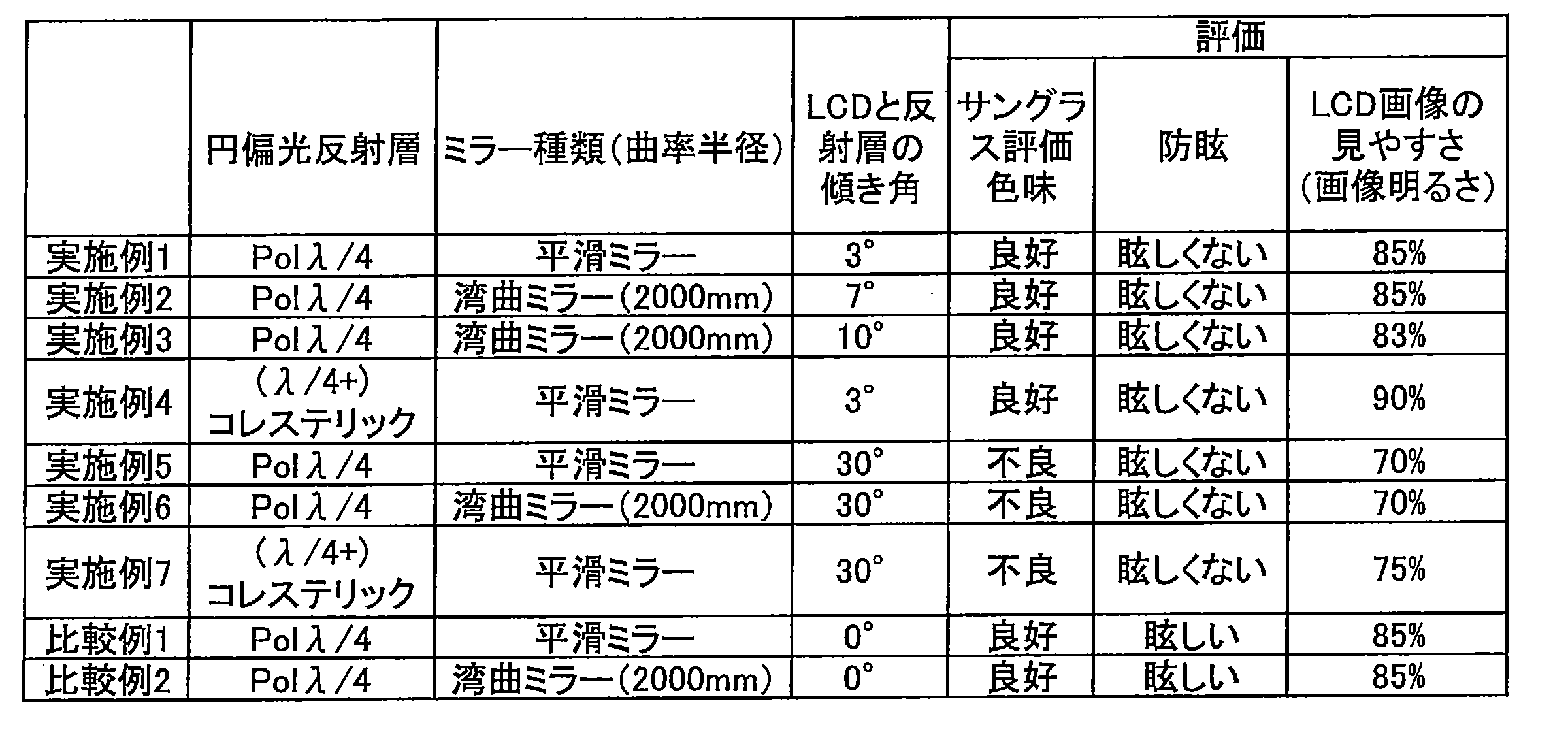
1 ハーフミラー
2 画像表示装置
6 フレーム
11 傾き角
2 画像表示装置
6 フレーム
11 傾き角
Claims (14)
- 車両用画像表示機能付きミラーであって、
画像表示装置およびハーフミラーを含み、
前記ハーフミラーは反射層を含み、
前記画像表示装置の画像表示部表面に対し前記反射層が傾斜している前記車両用画像表示機能付きミラー。 - 前記画像表示部表面に対する前記反射層の傾き角が3°~10°である請求項1に記載の車両用画像表示機能付きミラー。
- 前記反射層が円偏光反射層である請求項1または2に記載の車両用画像表示機能付きミラー。
- 前記円偏光反射層がコレステリック液晶層を含む請求項3に記載の車両用画像表示機能付きミラー。
- 前記円偏光反射層が3層以上のコレステリック液晶層を含む請求項4に記載の車両用画像表示機能付きミラー。
- 前記画像表示機能付きミラーが1/4波長板を含み、
前記画像表示装置、前記1/4波長板、前記円偏光反射層をこの順に含む請求項4または5に記載の車両用画像表示機能付きミラー。 - 前記円偏光反射層と前記1/4波長板とが互いに直接接している請求項6に記載の車両用画像表示機能付きミラー。
- 前記円偏光反射層が前記画像表示装置側から直線偏光反射板および1/4波長板を含む、請求項3に記載の車両用画像表示機能付きミラー。
- 前記ハーフミラーが、前面板を含み、
前記車両用画像表示機能付きミラーは前記画像表示装置、前記反射層、および前記前面板をこの順に含む請求項1~8のいずれか一項に記載の車両用画像表示機能付きミラー。 - 前記画像表示部表面と前記ハーフミラーとの間に空気層を含む請求項1~9のいずれか一項に記載の車両用画像表示機能付きミラー。
- 前記画像表示部表面と前記ハーフミラーとの間に接着層を含む、請求項1~9のいずれか一項に記載の車両用画像表示機能付きミラー。
- 前記画像表示装置と前記ハーフミラーとが前記ハーフミラーの側面に設けられるフレームで一体化されている請求項1~11のいずれか一項に記載の車両用画像表示機能付きミラー。
- 車両用画像表示機能付きミラーの製造方法であって、
画像表示装置の画像表示部表面に、反射層を含むハーフミラーを、前記ハーフミラーが前記画像表示部表面に対し傾斜するように配置することを含む製造方法。 - 前記傾斜の傾き角を決定することをさらに含む請求項13に記載の製造方法。
Priority Applications (3)
| Application Number | Priority Date | Filing Date | Title |
|---|---|---|---|
| EP16807492.0A EP3309010B1 (en) | 2015-06-09 | 2016-06-08 | Vehicle mirror with image display function and method of manufacturing the same |
| ES16807492T ES2744442T3 (es) | 2015-06-09 | 2016-06-08 | Espejo de vehículo con función de visualización de imagen y método de fabricación del mismo |
| US15/834,942 US10800333B2 (en) | 2015-06-09 | 2017-12-07 | Vehicle mirror with image display function and method of manufacturing the same |
Applications Claiming Priority (2)
| Application Number | Priority Date | Filing Date | Title |
|---|---|---|---|
| JP2015-116429 | 2015-06-09 | ||
| JP2015116429A JP6450264B2 (ja) | 2015-06-09 | 2015-06-09 | 車両用画像表示機能付きミラーおよび製造方法 |
Related Child Applications (1)
| Application Number | Title | Priority Date | Filing Date |
|---|---|---|---|
| US15/834,942 Continuation US10800333B2 (en) | 2015-06-09 | 2017-12-07 | Vehicle mirror with image display function and method of manufacturing the same |
Publications (1)
| Publication Number | Publication Date |
|---|---|
| WO2016199786A1 true WO2016199786A1 (ja) | 2016-12-15 |
Family
ID=57504088
Family Applications (1)
| Application Number | Title | Priority Date | Filing Date |
|---|---|---|---|
| PCT/JP2016/066981 Ceased WO2016199786A1 (ja) | 2015-06-09 | 2016-06-08 | 車両用画像表示機能付きミラーおよび製造方法 |
Country Status (5)
| Country | Link |
|---|---|
| US (1) | US10800333B2 (ja) |
| EP (1) | EP3309010B1 (ja) |
| JP (1) | JP6450264B2 (ja) |
| ES (1) | ES2744442T3 (ja) |
| WO (1) | WO2016199786A1 (ja) |
Families Citing this family (4)
| Publication number | Priority date | Publication date | Assignee | Title |
|---|---|---|---|---|
| US10434948B2 (en) * | 2016-06-03 | 2019-10-08 | Gentex Corporation | Display system with phase oriented reflective control |
| WO2018159340A1 (ja) * | 2017-03-03 | 2018-09-07 | パナソニックIpマネジメント株式会社 | 後方視認用車載表示装置 |
| CN208306497U (zh) * | 2018-06-15 | 2019-01-01 | 厦门盈趣汽车电子有限公司 | 一种大反射面积的流媒体自动防眩内后视镜 |
| JP7582306B2 (ja) * | 2020-04-28 | 2024-11-13 | Agc株式会社 | ハーフミラーの固定器具 |
Citations (10)
| Publication number | Priority date | Publication date | Assignee | Title |
|---|---|---|---|---|
| JPH07318928A (ja) * | 1994-05-24 | 1995-12-08 | Casio Comput Co Ltd | 液晶表示装置 |
| JPH11125717A (ja) * | 1997-10-22 | 1999-05-11 | Nitto Denko Corp | 偏光素子、偏光光源装置及び液晶表示装置 |
| JP2004004149A (ja) * | 2002-04-23 | 2004-01-08 | Nitto Denko Corp | ニュートラル偏光板および画像表示装置 |
| WO2013084622A1 (ja) * | 2011-12-09 | 2013-06-13 | 日産自動車株式会社 | 映像表示ミラー及び映像表示ミラーシステム |
| JP2013244753A (ja) * | 2012-05-23 | 2013-12-09 | Ichikoh Ind Ltd | 車両用インナーミラーシステム及びこの車両用インナーミラーシステムを備えた車両 |
| JP2013243971A (ja) * | 2012-05-28 | 2013-12-09 | Fujifilm Corp | 対象物に特定の円偏光を選択的に照射するためのシステム |
| WO2014112525A1 (ja) * | 2013-01-16 | 2014-07-24 | シャープ株式会社 | ミラーディスプレイ、ハーフミラープレート及び電子機器 |
| JP2014201146A (ja) * | 2013-04-03 | 2014-10-27 | 市光工業株式会社 | 車両用画像表示装置 |
| JP2014202928A (ja) * | 2013-04-05 | 2014-10-27 | 旭硝子株式会社 | ハーフミラー前面板 |
| WO2015050202A1 (ja) * | 2013-10-03 | 2015-04-09 | 富士フイルム株式会社 | 投映像表示用ハーフミラーおよび投映像表示システム |
Family Cites Families (9)
| Publication number | Priority date | Publication date | Assignee | Title |
|---|---|---|---|---|
| US6700692B2 (en) * | 1997-04-02 | 2004-03-02 | Gentex Corporation | Electrochromic rearview mirror assembly incorporating a display/signal light |
| US20040027694A1 (en) * | 2002-08-06 | 2004-02-12 | Mediaview Technologies Corporation | Adjustable segmented dual function mirror with video display |
| DE502005007961D1 (de) * | 2004-10-26 | 2009-10-01 | Volkswagen Ag | Rückspiegel für ein kraftfahrzeug |
| EP1926632A1 (en) * | 2005-09-05 | 2008-06-04 | Koninklijke Philips Electronics N.V. | Mirror device with a switchable cholesteric filter |
| JP5022869B2 (ja) * | 2007-11-20 | 2012-09-12 | 株式会社村上開明堂 | 発光表示装置付きバックミラー |
| US9254789B2 (en) * | 2008-07-10 | 2016-02-09 | Gentex Corporation | Rearview mirror assemblies with anisotropic polymer laminates |
| US9347649B2 (en) * | 2013-02-21 | 2016-05-24 | Pixtronix, Inc. | Display apparatus incorporating reflective and absorptive polarizers |
| WO2015050204A1 (ja) * | 2013-10-03 | 2015-04-09 | 富士フイルム株式会社 | 投映像表示用ハーフミラーおよび投映像表示システム |
| JP6425570B2 (ja) * | 2015-02-02 | 2018-11-21 | 日東電工株式会社 | 映像表示装置付のミラーを備える車両 |
-
2015
- 2015-06-09 JP JP2015116429A patent/JP6450264B2/ja active Active
-
2016
- 2016-06-08 ES ES16807492T patent/ES2744442T3/es active Active
- 2016-06-08 WO PCT/JP2016/066981 patent/WO2016199786A1/ja not_active Ceased
- 2016-06-08 EP EP16807492.0A patent/EP3309010B1/en active Active
-
2017
- 2017-12-07 US US15/834,942 patent/US10800333B2/en active Active
Patent Citations (10)
| Publication number | Priority date | Publication date | Assignee | Title |
|---|---|---|---|---|
| JPH07318928A (ja) * | 1994-05-24 | 1995-12-08 | Casio Comput Co Ltd | 液晶表示装置 |
| JPH11125717A (ja) * | 1997-10-22 | 1999-05-11 | Nitto Denko Corp | 偏光素子、偏光光源装置及び液晶表示装置 |
| JP2004004149A (ja) * | 2002-04-23 | 2004-01-08 | Nitto Denko Corp | ニュートラル偏光板および画像表示装置 |
| WO2013084622A1 (ja) * | 2011-12-09 | 2013-06-13 | 日産自動車株式会社 | 映像表示ミラー及び映像表示ミラーシステム |
| JP2013244753A (ja) * | 2012-05-23 | 2013-12-09 | Ichikoh Ind Ltd | 車両用インナーミラーシステム及びこの車両用インナーミラーシステムを備えた車両 |
| JP2013243971A (ja) * | 2012-05-28 | 2013-12-09 | Fujifilm Corp | 対象物に特定の円偏光を選択的に照射するためのシステム |
| WO2014112525A1 (ja) * | 2013-01-16 | 2014-07-24 | シャープ株式会社 | ミラーディスプレイ、ハーフミラープレート及び電子機器 |
| JP2014201146A (ja) * | 2013-04-03 | 2014-10-27 | 市光工業株式会社 | 車両用画像表示装置 |
| JP2014202928A (ja) * | 2013-04-05 | 2014-10-27 | 旭硝子株式会社 | ハーフミラー前面板 |
| WO2015050202A1 (ja) * | 2013-10-03 | 2015-04-09 | 富士フイルム株式会社 | 投映像表示用ハーフミラーおよび投映像表示システム |
Non-Patent Citations (1)
| Title |
|---|
| See also references of EP3309010A4 * |
Also Published As
| Publication number | Publication date |
|---|---|
| EP3309010A1 (en) | 2018-04-18 |
| ES2744442T3 (es) | 2020-02-25 |
| JP2017001494A (ja) | 2017-01-05 |
| US10800333B2 (en) | 2020-10-13 |
| EP3309010A4 (en) | 2018-05-30 |
| JP6450264B2 (ja) | 2019-01-09 |
| EP3309010B1 (en) | 2019-07-24 |
| US20180105110A1 (en) | 2018-04-19 |
Similar Documents
| Publication | Publication Date | Title |
|---|---|---|
| JP6579821B2 (ja) | 車両用の画像表示機能付きミラー | |
| US11142128B2 (en) | Anti-glare mirror with image display function | |
| JP2017227879A (ja) | ハーフミラーおよび画像表示機能付きミラー | |
| JP6632479B2 (ja) | ハーフミラーおよび画像表示機能付きミラー | |
| US10800333B2 (en) | Vehicle mirror with image display function and method of manufacturing the same | |
| WO2017221760A1 (ja) | ハーフミラーおよび画像表示機能付きミラー | |
| JP6572146B2 (ja) | ハーフミラーおよび画像表示機能付きミラー | |
| JP2017122776A (ja) | 画像表示機能付きミラーおよびハーフミラー | |
| JP6677607B2 (ja) | 画像表示機能付きミラーおよびハーフミラー | |
| JP2017227720A (ja) | 樹脂ミラー、画像表示機能付きミラー、樹脂ミラーの製造方法、および転写シート | |
| JP6574368B2 (ja) | 車両用の画像表示機能付きミラー | |
| WO2017208559A1 (ja) | ハーフミラーおよび画像表示機能付きミラー | |
| JP6793781B2 (ja) | 車両用の画像表示機能付きミラー | |
| JP7611973B2 (ja) | 車両用の画像表示機能付きミラー | |
| JP6806848B2 (ja) | 車両用の画像表示機能付きミラー | |
| JP6514232B2 (ja) | 車両用画像表示機能付きミラー | |
| WO2017183428A1 (ja) | 画像表示機能付きミラーおよびハーフミラー |
Legal Events
| Date | Code | Title | Description |
|---|---|---|---|
| 121 | Ep: the epo has been informed by wipo that ep was designated in this application |
Ref document number: 16807492 Country of ref document: EP Kind code of ref document: A1 |
|
| NENP | Non-entry into the national phase |
Ref country code: DE |
|
| WWE | Wipo information: entry into national phase |
Ref document number: 2016807492 Country of ref document: EP |