WO2016199863A1 - 製袋機 - Google Patents
製袋機 Download PDFInfo
- Publication number
- WO2016199863A1 WO2016199863A1 PCT/JP2016/067252 JP2016067252W WO2016199863A1 WO 2016199863 A1 WO2016199863 A1 WO 2016199863A1 JP 2016067252 W JP2016067252 W JP 2016067252W WO 2016199863 A1 WO2016199863 A1 WO 2016199863A1
- Authority
- WO
- WIPO (PCT)
- Prior art keywords
- bottom material
- slit
- making machine
- end surface
- bag making
- Prior art date
- Legal status (The legal status is an assumption and is not a legal conclusion. Google has not performed a legal analysis and makes no representation as to the accuracy of the status listed.)
- Ceased
Links
Images




Classifications
-
- B—PERFORMING OPERATIONS; TRANSPORTING
- B31—MAKING ARTICLES OF PAPER, CARDBOARD OR MATERIAL WORKED IN A MANNER ANALOGOUS TO PAPER; WORKING PAPER, CARDBOARD OR MATERIAL WORKED IN A MANNER ANALOGOUS TO PAPER
- B31B—MAKING CONTAINERS OF PAPER, CARDBOARD OR MATERIAL WORKED IN A MANNER ANALOGOUS TO PAPER
- B31B70/00—Making flexible containers, e.g. envelopes or bags
- B31B70/02—Feeding or positioning sheets, blanks or webs
- B31B70/10—Feeding or positioning webs
-
- B—PERFORMING OPERATIONS; TRANSPORTING
- B31—MAKING ARTICLES OF PAPER, CARDBOARD OR MATERIAL WORKED IN A MANNER ANALOGOUS TO PAPER; WORKING PAPER, CARDBOARD OR MATERIAL WORKED IN A MANNER ANALOGOUS TO PAPER
- B31B—MAKING CONTAINERS OF PAPER, CARDBOARD OR MATERIAL WORKED IN A MANNER ANALOGOUS TO PAPER
- B31B50/00—Making rigid or semi-rigid containers, e.g. boxes or cartons
- B31B50/14—Cutting, e.g. perforating, punching, slitting or trimming
- B31B50/16—Cutting webs
- B31B50/18—Cutting webs longitudinally
-
- B—PERFORMING OPERATIONS; TRANSPORTING
- B29—WORKING OF PLASTICS; WORKING OF SUBSTANCES IN A PLASTIC STATE IN GENERAL
- B29C—SHAPING OR JOINING OF PLASTICS; SHAPING OF MATERIAL IN A PLASTIC STATE, NOT OTHERWISE PROVIDED FOR; AFTER-TREATMENT OF THE SHAPED PRODUCTS, e.g. REPAIRING
- B29C69/00—Combinations of shaping techniques not provided for in a single one of main groups B29C39/00 - B29C67/00, e.g. associations of moulding and joining techniques; Apparatus therefore
- B29C69/02—Combinations of shaping techniques not provided for in a single one of main groups B29C39/00 - B29C67/00, e.g. associations of moulding and joining techniques; Apparatus therefore of moulding techniques only
-
- B—PERFORMING OPERATIONS; TRANSPORTING
- B29—WORKING OF PLASTICS; WORKING OF SUBSTANCES IN A PLASTIC STATE IN GENERAL
- B29D—PRODUCING PARTICULAR ARTICLES FROM PLASTICS OR FROM SUBSTANCES IN A PLASTIC STATE
- B29D24/00—Producing articles with hollow walls
-
- B—PERFORMING OPERATIONS; TRANSPORTING
- B31—MAKING ARTICLES OF PAPER, CARDBOARD OR MATERIAL WORKED IN A MANNER ANALOGOUS TO PAPER; WORKING PAPER, CARDBOARD OR MATERIAL WORKED IN A MANNER ANALOGOUS TO PAPER
- B31B—MAKING CONTAINERS OF PAPER, CARDBOARD OR MATERIAL WORKED IN A MANNER ANALOGOUS TO PAPER
- B31B50/00—Making rigid or semi-rigid containers, e.g. boxes or cartons
- B31B50/02—Feeding or positioning sheets, blanks or webs
- B31B50/10—Feeding or positioning webs
-
- B—PERFORMING OPERATIONS; TRANSPORTING
- B31—MAKING ARTICLES OF PAPER, CARDBOARD OR MATERIAL WORKED IN A MANNER ANALOGOUS TO PAPER; WORKING PAPER, CARDBOARD OR MATERIAL WORKED IN A MANNER ANALOGOUS TO PAPER
- B31B—MAKING CONTAINERS OF PAPER, CARDBOARD OR MATERIAL WORKED IN A MANNER ANALOGOUS TO PAPER
- B31B70/00—Making flexible containers, e.g. envelopes or bags
- B31B70/14—Cutting, e.g. perforating, punching, slitting or trimming
- B31B70/16—Cutting webs
- B31B70/18—Cutting webs longitudinally
-
- B—PERFORMING OPERATIONS; TRANSPORTING
- B31—MAKING ARTICLES OF PAPER, CARDBOARD OR MATERIAL WORKED IN A MANNER ANALOGOUS TO PAPER; WORKING PAPER, CARDBOARD OR MATERIAL WORKED IN A MANNER ANALOGOUS TO PAPER
- B31B—MAKING CONTAINERS OF PAPER, CARDBOARD OR MATERIAL WORKED IN A MANNER ANALOGOUS TO PAPER
- B31B70/00—Making flexible containers, e.g. envelopes or bags
- B31B70/26—Folding sheets, blanks or webs
- B31B70/262—Folding sheets, blanks or webs involving longitudinally folding, i.e. along a line parallel to the direction of movement
- B31B70/266—Folding sheets, blanks or webs involving longitudinally folding, i.e. along a line parallel to the direction of movement involving gusset-forming
-
- B—PERFORMING OPERATIONS; TRANSPORTING
- B31—MAKING ARTICLES OF PAPER, CARDBOARD OR MATERIAL WORKED IN A MANNER ANALOGOUS TO PAPER; WORKING PAPER, CARDBOARD OR MATERIAL WORKED IN A MANNER ANALOGOUS TO PAPER
- B31B—MAKING CONTAINERS OF PAPER, CARDBOARD OR MATERIAL WORKED IN A MANNER ANALOGOUS TO PAPER
- B31B2155/00—Flexible containers made from webs
- B31B2155/001—Flexible containers made from webs by folding webs longitudinally
-
- B—PERFORMING OPERATIONS; TRANSPORTING
- B31—MAKING ARTICLES OF PAPER, CARDBOARD OR MATERIAL WORKED IN A MANNER ANALOGOUS TO PAPER; WORKING PAPER, CARDBOARD OR MATERIAL WORKED IN A MANNER ANALOGOUS TO PAPER
- B31B—MAKING CONTAINERS OF PAPER, CARDBOARD OR MATERIAL WORKED IN A MANNER ANALOGOUS TO PAPER
- B31B2160/00—Shape of flexible containers
- B31B2160/20—Shape of flexible containers with structural provision for thickness of contents
Definitions
- This invention relates to a bag making machine for producing plastic bags.
- first and second body materials are overlapped with each other and fed in the length direction. And a plastic bag is manufactured with the 1st and 2nd body. The same is true for the bag making machine described in Patent Documents 2-5.
- the plastic bag has a front surface, a rear surface, and one end surface. And before superposition
- the plastic film is slit along the longitudinal slit line before the body is overlapped, and divided into the first body and the bottom material. Further, the bottom material is guided by the bottom material guide mechanism, the bottom material is supplied to the first or second body, the front and rear surfaces are formed by the first and second bodies, and the one end surface is formed by the bottom material.
- the bottom material is supplied to the first or second body material, and is arranged along the longitudinal center line. Thereafter, the bottom material is slit along its longitudinal centerline. Before or after the bottom material is supplied, the first and second body members are also slit along their longitudinal centerlines. Accordingly, two plastic bags are manufactured, and in each plastic bag, the front surface and the rear surface are formed by the first and second body members, and the one end surface is formed by the bottom material.
- the bag making machine is called two-row picking because two pieces are manufactured.
- the plastic film can be slit along its longitudinal slit line and divided into a first body and a bottom material.
- the plastic film can be supplied from the supply roll and divided into the first body and the bottom material, and it is not necessary to supply the bottom material separately. Therefore, the configuration of the bag making machine is simplified and the cost is low. When printing is performed, there is no deviation in the printed pattern between the body and the bottom material.
- the plastic bag has the other end surface in addition to the front surface, the rear surface, and one end surface.
- two bottom materials are supplied to the 1st or 2nd body material, and are arranged along the both-sides edge. Therefore, a front surface and a rear surface are formed by the first and second body members, and one end surface is formed by one of the bottom materials, and the other end surface is formed by the other bottom material.
- This bag making machine is called single row picking, and plastic bags are manufactured one by one.
- a specific bottom material has a width twice that of the other bottom materials.
- a specific bottom material is supplied to the first or second body and arranged along the longitudinal center line, and another bottom material is supplied to the first or second body, and on both side edges thereof. Arrange along.
- the specific bottom material is slit along the longitudinal center line.
- the first and second body members are also slit along the longitudinal centerline.
- the first or second body is guided by the body guide mechanism, and the first or second body is bent along one side edge thereof. Folded, thereby forming a double fold. Therefore, the front surface and the rear surface are formed by the first and second body members, and the one end surface is formed by the two-folded portion.
- the bottom material is supplied to the first or second body, and is arranged along the longitudinal center line. Thereafter, the bottom material is slit along its longitudinal centerline. Before or after the bottom material is supplied, the first and second body members are also slit along the longitudinal centerline.
- an object of the present invention is to eliminate the problem that the bottom material does not need to be separately supplied and the printed pattern is displaced in a bag making machine that uses the bottom material to manufacture a plastic bag. .
- the first and second body members are overlapped with each other and fed in the length direction.
- the plastic film is slit along the longitudinal slit line by the first slit mechanism before the body is overlapped, and is divided into the first body and the bottom material.
- segmentation the 1st and 2nd body material is piled up mutually, and is sent to a length direction.
- the bottom material after slitting is sent in the length direction by the bottom material feed mechanism, the bottom material is further slit into a plurality of bottom materials by the second slit mechanism, and slit by the bottom material guide mechanism.
- a plurality of subsequent bottom materials are guided and supplied to the first or second body. Therefore, according to this invention, a plurality of plastic bags can be manufactured, and in each plastic bag, the front and rear surfaces can be formed by the first and second body members, and the one end surface can be formed by the bottom material.
- the bottom material is further slit into three bottom materials by the second slit mechanism.
- the specific bottom material has a width twice that of the other bottom materials, the specific bottom material is supplied to the first or second body, Arranged along.
- the other bottom material is supplied to the first or second body and is disposed along both side edges.
- the specific bottom material is slit along the longitudinal center line, and before or after the supply of the bottom material, the first and second body members are also along the longitudinal center line. Is slit. Therefore, two plastic bags are manufactured, and in each plastic bag, the front and rear surfaces are formed by the first and second body members, one end surface is formed by a specific bottom material, and the other end surface is formed by another bottom material. It is formed.
- the side gusset material is supplied to the first or second body material before the body material is superimposed,
- the side gusset material is arranged between the first and second body members when arranged in the width direction and the first and second body members are overlapped with each other. Therefore, both side surfaces are formed by the side gusset material.
- the bottom material is further slit into two bottom materials by the second slit mechanism, and each bottom material is supplied to the first or second body material and arranged along both side edges thereof.
- the first and second body members are slit along their longitudinal centerlines. Accordingly, two plastic bags are manufactured, and in each plastic bag, the front surface and the rear surface are formed by the first and second body members, and the one end surface is formed by the bottom material.
- each bottom material is supplied to the first or second body and arranged along both side edges. And you may make it form a front surface and a rear surface with the 1st and 2nd trunk
- ⁇ Slit the plastic film along its longitudinal slit and divide it into a first body and a bottom.
- the bottom material after being slit is fed in the length direction by the bottom material feeding mechanism.
- a bottom material is supplied to a 1st or 2nd trunk
- the first or second body is guided by the body guide mechanism, and the first or second body is bent along the both side edges and folded, thereby forming a folded portion. To do.
- the bottom material is supplied, the bottom material is slit along its longitudinal slit line.
- the first and second body members are also slit along the longitudinal centerline.
- two plastic bags are manufactured, and in each plastic bag, the front and rear surfaces are formed by the first and second body members, one end surface is formed by the bottom material, and the other end surface is formed by the two-folded portion. It may be.
- the bottom material feed mechanism is composed of rollers. Further, a dancer roller is provided adjacent to the upstream side of the bottom material feed mechanism, and the feed amount of the bottom material is absorbed by the dancer roller.
- A is a plan view showing an embodiment of the present invention
- B is a plan view showing a state in which the wide bottom material of A is slit
- C is a plan view showing a state in which the first body of A is bent
- D is another It is explanatory drawing which shows the Example.
- A is a side view of the bag making machine of FIG. 1, and B is a side view showing a vertical sealing device, a horizontal sealing device, and a cutter of the bag making machine of A.
- FIG. A is a plan view showing a plastic bag obtained by the bag making machine of FIG. 1, and B is an exploded view of the plastic bag of A.
- FIG. A is an explanatory view showing another embodiment
- B is an explanatory view showing another embodiment.
- A is a plan view showing another embodiment, B is a side view of A's bag making machine, and C is a side view showing a vertical sealing device, a horizontal sealing device and a cutter of B's bag making machine.
- A is a plan view showing a plastic bag obtained by the bag making machine of FIG. 5, and B is an exploded view of the plastic bag of A.
- FIG. A is a side view showing another embodiment, and B is a side view showing a vertical sealing device, a horizontal sealing device, and a cutter of A's bag making machine.
- A is a plan view showing a plastic bag obtained by the bag making machine of FIG. 7, and B is an exploded view of the plastic bag of A.
- A is a plan view showing another embodiment
- B is a plan view showing a state where the first and second body members of A are bent
- C is a cross-sectional view of the first and second body members of B
- D is C
- FIG. 6 is a cross-sectional view showing a state in which the first and second body members are folded
- E is a cross-sectional view showing a state in which the first body member of D is folded back and the second body member is folded back.
- A is a side view of the bag making machine of FIG. 9, and B is a side view showing a vertical sealing device, a horizontal sealing device, and a cutter of the bag making machine of A.
- FIG. A is a plan view showing a plastic bag obtained by the bag making machine of FIG. 9, and B is an exploded view of the plastic bag of A.
- FIG. 1 shows a bag making machine according to the present invention.
- This bag making machine is for producing the plastic bag of FIG.
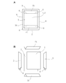
- the plastic bag of FIG. 3 uses the first and second body materials 1, 2 and the bottom material 3, and has a front surface, a rear surface, and one end surface. 1 and second body members 1 and 2, and one end surface of the bottom member 3.
- this plastic bag uses the bottom material 4 and the side gusset material 5, and has the other end surface and both side surfaces in addition to the front surface, the rear surface, and one end surface, and the other end surface. Consists of a bottom material 4. Both side surfaces are made of side gusset material 5.
- Auxiliary gusset portions 6 are formed at both ends of the side gusset material 5, and one end edge 7, the other end edge 8, and both side edges 9 are formed by the first and second body materials 1, 2.
- the side gusset material 5 is heat-sealed along the side edges 9, the auxiliary gusset portion 6 and the bottom materials 3, 4 are heat-sealed along the side edges 9, and the heat seal line 10 is formed along the side edges 9. This is also the same as the plastic bag of Patent Document 4.
- the body materials 1 and 2 and the bottom material 3 are heat-sealed along one end edge 7, the heat seal line 10 is formed along the one end edge 7, and the body materials 1 and 2 and the bottom material 4 are formed at the other end edge.
- the heat seal line 10 is formed along the other end edge 8.
- the first and second body members 1, 2 are overlapped with each other and fed in the length direction.
- a body feed roller 11 is used in the body feed mechanism, and the first and second body 1 and 2 are guided to the feed roller 11, and the feed roller 11 is driven by a drive motor. Is driven and rotated, and the first and second body members 1 and 2 are fed in the length direction thereof.
- the feed roller 11 rotates intermittently, and in the feed direction X, the first and second body materials 1 and 2 are fed intermittently.
- the plastic film is supplied from the supply roll 12, guided to the slit mechanism, and slit along the plurality of longitudinal slit lines 13 and 14. And divided into a first body 1 and a plurality of bottom members 3 and 4.
- a plastic film is slit along three longitudinal slit lines 13 and 14 and divided into a first body 1 and three bottom members 3 and 4.
- a plastic film slit blade 15 is used for the slit mechanism, the plastic film is guided to the slit blade 15, and the plastic film is slit by the slit blade 15 as the plastic film is fed. Therefore, first, the plastic film is slit along the longitudinal slit line 13 and divided into the first body 1 and the wide bottom member 16.
- the plastic film is a printed pattern repeatedly printed. Further, the wide bottom material 16 is guided to the bottom material guide mechanism, and the wide bottom material 16 is guided by the bottom material guide mechanism.
- a plurality of guide rollers 17, 18, 19 are used in the bottom material guide mechanism, and the wide bottom material 16 passes through the guide roller 17, is guided to the guide roller 18, is lifted, and is guided to the guide roller 19, Descend. Thereby, the position of the printed pattern is adjusted.
- the guide roller 18 may be a dancer roller.
- the second body 2 is also made of a plastic film and supplied from its supply roll 20.
- the second body 2 is guided to the lower side of the first body 1 and extends in the length direction thereof.
- the first body 1 is the upper body
- the second body 2 is the lower body.
- a plurality of turn bars or turn rollers 21 are used for the bottom material guide mechanism, the wide bottom material 16 is guided by the turn bar or turn roller 21, the direction is changed, and the wide bottom material 16 is the same as that of the first body 1. It is guided to the upper side and extends in the length direction.
- a guide roller 22 is used for the bottom material guide mechanism.
- the wide bottom material 16 passes through the guide roller 22, is guided to the dancer roller 23, is lowered, and is guided to the feed roller 24. ,To rise.
- the feed roller 24 is driven and rotated by the drive motor, and the wide bottom material 16 is fed in the length direction.
- the feed roller 24 rotates intermittently, and the wide bottom material 16 is intermittently fed in the same manner as the first and second body members 1 and 2.
- two slit blades 25 are used for the slit mechanism, the wide bottom material 16 is guided to the slit blade 25, and the wide bottom material 16 is slit by the slit blade 25 as the wide bottom material 16 is fed. The Therefore, the wide bottom material 16 is slit along the two longitudinal slit lines 14 and divided into three bottom materials 3 and 4.
- the plastic film is slit along the longitudinal slit line 13 by the first slit mechanism before the body materials 1 and 2 are overlapped, and divided into the first body material 1 and the bottom material 16. Is done.
- the first slit mechanism includes a slit blade 15. And after a division
- the bottom material 16 after slitting is sent in the length direction by the bottom material feed mechanism, and the bottom material 16 is further slit into a plurality of bottom materials 3 and 4 by the second slit mechanism, and the bottom material guide mechanism
- the plurality of bottom materials 3 and 4 after being slit are guided and supplied to the first or second body materials 1 and 2.
- the bottom material feed mechanism includes a feed roller 24.
- the second slit mechanism includes a slit blade 25.
- the feed roller 24 is used for the bottom material feeding mechanism, and the bottom material 16 after being slit is fed by the bottom material feeding mechanism in the length direction, which is particularly important.
- the bottom 16 is usually narrower than the barrels 1 and 2, and if it is not sent in the length direction, phenomena such as sagging, flapping, and sometimes tearing may occur, resulting in inconvenience in bag making. There is. Therefore, in this bag making machine, by providing a bottom material feeding mechanism that sends the bottom material 16 after the slit in the length direction, the bottom material 16 after the slit does not sag, flutter, or tear off, A reliable bag-making process was made possible.
- the plastic film is guided to the slit mechanism and slit along the three longitudinal slit lines 13 and 14, and divided into the first body 1 and the three bottom members 3 and 4. Is done.
- the slit mechanism includes three slit blades 15 and 25. In the width direction of the plastic film, the slit blades 15 and 25 are arranged at intervals, and the plastic film is slit and divided by the slit blades 15 and 25 as the plastic film is fed.
- the first body 1 is guided by the guide roller 26, the first body 1 passes through the guide roller 26, is guided to the feed roller 11, and descends.
- the second body 2 is also guided to the feed roller 11. Therefore, the first and second body materials 1 and 2 are overlapped with each other and fed in the length direction.
- the feed rollers 11 and 24 rotate intermittently, the first and second body materials 1 and 2 are intermittently fed, and the wide bottom material 16 is also intermittently fed, but is supplied from the supply roll 12.
- the plastic film is continuously fed. Therefore, after the slit, the first body 1 is continuously fed, and the wide bottom material 16 is also continuously fed.
- the second body 2 is also continuously fed.
- the wide bottom material 16 is guided to the dancer roller 23 and the feed roller 24, the feed roller 24 rotates intermittently, and the wide bottom material 16 is intermittently fed. Accordingly, there is a problem in that the feed amount varies, but as the wide bottom material 16 is fed, the dancer roller 23 rises and falls due to tension, and the dancer roller 23 absorbs the feed amount.
- first and second body members 1 and 2 are guided to a dancer roller (not shown), the dancer roller is raised and lowered by the tension, and the feed amount is absorbed by the dancer roller.
- the plastic film is divided into the first body 1 and the three bottom members 3 and 4, and thereafter, each bottom member 3 and 4 is guided by the bottom member guide mechanism,
- the materials 3 and 4 are supplied to the first or second body materials 1 and 2.
- the specific bottom material 3 has a width twice that of the other bottom material 4
- the specific bottom material 3 is the first or second body material. 1 and 2 are arranged along the longitudinal center line.
- the other bottom material 4 is supplied to the first or second body 1, 2 and is disposed along both side edges 27.
- a plurality of turn bars or turn rollers 28 are used for the bottom material guide mechanism, and the other bottom material 4 is redirected by the turn bar or turn roller 28, and the other bottom material 4 in the width direction of the specific bottom material 3. Is separated from the specific bottom material 3, and then, on both sides of the specific bottom material 3, the other bottom materials 4 are arranged in parallel to the specific bottom material 3. Further, the bottom material guide rollers 29 and 30 are used for the bottom material guide mechanism, and the respective bottom materials 3 and 4 pass through the guide roller 29 and are guided to the guide roller 30. And the specific bottom material 3 is supplied to the 1st or 2nd trunk
- the side gusset material 5 is pre-folded into two parts before the body materials 1 and 2 are overlapped, and every time the body materials 1 and 2 are intermittently fed. 1 and 2 and arranged in the width direction.
- the side gusset material supply mechanism 31 folds and supplies the side gusset material 5 in two.
- a side gusset material supply robot is used for the side gusset material supply mechanism 31, and the side gusset material 5 is divided into two in the length direction of the side gusset material 5, and after the division, the side gusset material 5 is supplied by the robot. .
- the side gusset material 5 is supplied to the second body 2 and arranged in the width direction, and then the first and second bodies 1 and 2 are overlapped with each other, and the side gusset material 5 is the first. And between the second body members 1 and 2.
- each bottom material 3, 4 is supplied to the first body 1, but after the supply of the bottom material 3, 4, the specific bottom material 3 extends along its longitudinal center line. It is slit. Further, before or after the bottom materials 3 and 4 are supplied, the first and second body materials 1 and 2 are also slit along the longitudinal center line.
- the first body material 1 is guided to the slit mechanism, slit along the longitudinal center line, and divided in the width direction. Is done.
- two slit blades 32 are used for the slit mechanism, and the slit blades 32 are arranged at intervals in the width direction of the first body 1.
- the first body 1 is fed, the first body 1 is slit by the slit blade 32 and divided. Therefore, the first body 1 is slit along the two longitudinal slit lines 33, and the waste 34 is generated in the first body 1, and the waste 34 passes through the guide roller 35 and is collected upward. As a result, a divided side edge 36 of the first body 1 is formed.
- the side gusset material 5 is divided into two parts, but the first body 1 is attached to the side gusset material 5 and temporarily fixed at both ends of the two divided side gusset materials 5.
- the second body 2 is also attached to the side gusset material 5 and temporarily fixed.
- a heat sealing device or an ultrasonic sealing device is used as the temporary fixing mechanism 37, and the first and second body materials 1, 2 and the side gusset material 5 are heat sealed or ultrasonic sealed by the heat sealing device or the ultrasonic sealing device. And temporarily fixed.
- the position is the position of the longitudinal center line of the side gusset material 5.
- each bottom material 3, 4 is guided to the guide roller 30, supplied to the first body 1, arranged along the longitudinal center line and both side edges 27, and superimposed on the outer surface. Furthermore, like the bag making machine of Patent Document 3, after the supply of each bottom material 3, 4, a specific bottom material 3 is attached to the second body 2 between the divided side edges 33 of the first body 1, Temporarily fixed. Further, in the vicinity of the side edges 27 of the first body 1, the other bottom material 4 is also attached to the second body 2 and temporarily fixed.
- a heat sealing device or an ultrasonic sealing device is used as the temporary fixing mechanism 38, and the specific bottom material 3, the other bottom material 4, and the second body material 2 are heat sealed or superposed by the heat sealing device or the ultrasonic sealing device. Sound-sealed and temporarily fixed.
- the first and second body members 1 and 2 are guided to the body member guide mechanism 39, and the body member guide mechanism 39 moves the first body member 1 and 2 as the body members 1 and 2 are fed.
- the second body 1 and 2 are guided, and the first body 1 is bent along its longitudinal folding line in the vicinity of the split side edge 36 of the first body 1 and folded back to the original state. It is. Further, in the vicinity of both side edges 27 of the first body 1, the first body 1 is folded along its longitudinal fold line and folded back to the original state.
- the body guide mechanism 39 is the same as that of Patent Document 3, and includes a guide rod or a guide plate. Then, the first body 1 is bent and folded back by the guide rod or the plate.
- the side gusset material 5 is opened and closed by the first body 1, the auxiliary gusset portion 6 is formed, and the specific bottom material is formed by the first body 1. 3 is folded and folded in two, and this is combined with the auxiliary gusset portion 6 and disposed between the first and second body members 1.
- the side gusset material 5 is opened and closed by the first body 1 to form the auxiliary gusset portion 6, and the other bottom is formed by the first body 1.
- the material 4 is bent and folded in half, and this is combined with the auxiliary gusset portion 6 and disposed between the first and second body members 1.
- the bottom members 3, 4 and the auxiliary gusset portion 6 are moved by the temporary fixing mechanism. Heat sealing or ultrasonic sealing may be performed, and temporary fixing may be performed to form the temporary fixing portion 40 (FIG. 1D).
- first and second body members 1 and 2 are guided to the longitudinal sealing device 41 and the lateral sealing device 42, and the longitudinal sealing device 41 performs the first longitudinal sealing device 41 in the longitudinal direction for each intermittent feed of the body members 1 and 2.
- the second body materials 1 and 2 and the specific bottom material 3 are heat-sealed, and the first and second body materials 1 and 2 and the other bottom material 4 are heat-sealed.
- the first and second body members 1, 2 and the specific bottom member 3 are heat-sealed along the longitudinal center lines of the first and second body members 1, 2, and the first and second body members 1, 2 are sealed.
- the other bottom material 4 is heat-sealed along the side edges 27 of the first and second body members 1 and 2.
- first and second body materials 1 and 2 and the side gusset material 5 are heat-sealed by the lateral sealing device 42 in the width direction.
- the first and second body members 1, 2 and the side gusset material 5 are heat-sealed along the longitudinal center line of the side gusset material 5.
- the first and second body members 1 and 2 and the specific bottom material 3 are not heat-sealed by the vertical sealing device 41, but one body material and the specific bottom material 3 are heat-sealed, and the other body material and The specific bottom material 3 is not heat sealed. Then, after the plastic bag is manufactured, the contents are passed between the other body material and the specific bottom material 3 and filled into the plastic bag. Thereafter, the other body material and the specific bottom material 3 may be heat sealed.
- the first and second body materials 1 and 2 and the other bottom material 4 are not heat-sealed by the vertical sealing device 41, but one body material and the other bottom material 4 are heat-sealed, and the other body material and The other bottom material 4 is not heat sealed. Then, after manufacturing the plastic bag, the contents are passed between the other body material and the other bottom material 4 to fill the plastic bag. Thereafter, the other body member and the other bottom member 4 may be heat sealed.
- the specific bottom member 3 is slit along the longitudinal center line thereof, and the second body member 2 is also centered in the longitudinal direction. Slit along the line.
- the bottom material and the body slit blade 43 are used for the slit mechanism, and the specific bottom material 3 and the second body 2 are slit by the slit blade 43 as the body materials 1 and 2 are fed.
- the first body 1 is already slit.
- Two slit blades 43 are used for the slit mechanism, and the slit blades 43 are arranged at intervals in the width direction of the first and second body members 1 and 2, and the interval is larger than the interval between the slit blades 32. Set larger. Then, the specific bottom material 3 and the second body 2 may be slit by the slit blade 43, and the first body 1 may also be slit.
- first and second body members 1 and 2 are guided to the cutter 44, and the first and second body members 1 and 2 are cut by the cutter 44 in the width direction for each intermittent feed of the body members 1 and 2.
- the specific bottom material 3, the other bottom material 4, and the side gusset material 5 are cross-cut.
- the first and second body materials 1 and 2, the specific bottom material 3, the other bottom material 4 and the side gusset material 5 are cross-cut along the longitudinal center line of the side gusset material 5.
- both plastic bags are manufactured, and in each plastic bag, the front and rear surfaces are formed by the first and second body members 1 and 2, one end surface is formed by the specific bottom material 3, and the other bottom materials The other end surface is formed by 4. Further, both side surfaces are formed by the side gusset material 5.
- the bottom material feed mechanism feeds the bottom material 16 after slitting in the length direction, so that the bottom material 16 after slitting does not sag, flutter, or tear, and a reliable bag making can be achieved. As described above, this is possible.
- the first body member 1 when the first and second body members 1 and 2 are overlapped with each other after the division, the first body member 1 is the upper body member, and the second body member 2 is the lower body member.
- the material is described as a material, it is not always necessary.
- the first body 1 may be a lower body
- the second body 2 may be an upper body.
- the plastic film is supplied from the supply roll, and the plastic film is slit by the slit blade 45 in the same manner as that described in Patent Document 2, and this is divided into the first and second barrels 1, 2. Divide into two (FIG. 4A). Further, the plastic film is slit by the slit blade 46 and divided into the first body 1 and the wide bottom material 16. Further, the first and second body members 1 and 2 are guided by the guide plate 47 and changed in direction, and then the first and second body members 1 and 2 are overlapped with each other and sent in the length direction.
- the wide bottom material 16 is guided by the turn bar or turn roller 48 and the guide roller 49 to change the direction. Further, similarly to the embodiment of FIG. 1, the wide bottom material 16 is slit by a slit blade, the wide bottom material 16 is divided into three bottom materials 3 and 4, and each bottom material 3 and 4 is You may make it supply to the 1st or 2nd trunk
- the plastic film is slit along the longitudinal slit line and divided into the first body 1 and the second body 2. Further, the plastic film is slit along three longitudinal slit lines and divided into the first body 1 and the three bottom members 3 and 4. Therefore, a total of four slit blades are used, and the plastic film is slit by each slit blade. It is also conceivable to simultaneously slit the plastic film at each longitudinal slit line.
- the plastic film is supplied from the supply roll, the plastic film is slit by the slit blade 45, and is divided into the first body 1 and the wide bottom material 16 (FIG. 4B). Further, the first body 1 is guided by the guide plate 47 and the direction is changed. Further, as in the embodiment of FIG. 1, the second body 2 is supplied from the supply roll, and then the first and second bodies 1 and 2 are overlapped with each other and fed in the length direction. Further, the wide bottom material 16 may be guided by the turn bar or the turn roller 50 and changed in direction, and then the wide bottom material 16 may be divided into three bottom materials 3 and 4.
- FIG. 5 shows another embodiment.
- This embodiment is another type of bag making machine for manufacturing the plastic bag of FIG.
- the plastic bag of FIG. 6 has a front surface, a rear surface, and one end surface, the front surface and the rear surface are composed of the first and second body materials 1 and 2, and the one end surface is composed of the bottom material 51.
- this plastic bag has both side surfaces, and both side surfaces are made of side gusset material 5.
- an auxiliary gusset portion 6 is formed at one end of the side gusset material 5, the body materials 1, 2 and the side gusset material 5 are heat-sealed along both side edges 9, and the auxiliary gusset portion 6 and the bottom material 51 are both side edges.
- the heat-seal line 10 is formed along both side edges 9. Further, the body materials 1 and 2 and the bottom material 51 are heat-sealed along the one end edge 7, and the heat seal line 10 is formed along the one end edge 7.
- the first and second body materials 1, 2 are overlapped with each other and fed in the length direction.
- the feed roller 11 is used in the body feeding mechanism, and the first and second body 1 and 2 are intermittently fed as in the bag making machine of FIG.
- the plastic film is supplied from the supply roll 12 and guided to the slit blade 15 before the body materials 1 and 2 are superposed. It is slit along the direction slit line 13, and is slit into the first body 1 and the wide bottom material 16. Thereafter, in this bag making machine, the wide bottom material 16 is guided to the slit blade 52, slit along the longitudinal slit line 53, and divided into two bottom materials 51. Accordingly, the plastic film is slit along the two longitudinal slit lines 13.53, and is divided into the first body 1 and the two bottom members 51.
- the plastic film is slit along the longitudinal slit line 13 by the first slit mechanism, and divided into the first body 1 and the bottom material 16, and by the second slit mechanism,
- the bottom material 16 is further slit into a plurality of bottom materials 51.
- the first slit mechanism is composed of a slit blade 15
- the second slit mechanism is composed of a slit blade 52.
- the plastic film may be slit at the longitudinal slit lines 13 and 53 at the same time.
- first and second body materials 1 and 2 are guided to the feed roller 11, overlapped with each other, and the first and second body materials 1 and 2 are fed by the feed roller 11.
- a turn bar or turn roller 54 is used for the bottom material guide mechanism, and each bottom material 51 is guided and changed in direction by the turn bar or turn roller 54.
- each bottom material 51 is supplied to the 1st or 2nd body materials 1 and 2, and is arrange
- each bottom material 51 is guided to the guide roller 30, supplied to the first body 1, arranged on both side edges, and overlapped on the outer surface.
- the side gusset material 5 is supplied by the side gusset material supply mechanism, and the side gusset material 5 is arranged in the width direction of the body materials 1 and 2. Is done. However, when supplied, the side gusset material 5 is not divided into two. The first and second body materials 1, 2 and the side gusset material 5 are temporarily fixed by the temporary fixing mechanism 37 at both ends of the side gusset material 5, as in the bag making machine of FIG.
- each bottom material 51 and the second material 2 are temporarily fixed by the temporary fixing mechanism 38 in the vicinity of both side edges of the first body 1 as in the bag making machine of FIG. . Thereafter, in the vicinity of both side edges of the first body 1, the first body 1 is folded and folded by the body guide mechanism 39. Therefore, the side gusset material 5 is opened and closed by the first body 1, the auxiliary gusset portion 6 is formed, the respective bottom materials 51 are folded in two, and this is combined with the auxiliary gusset portion 6.
- the first and second body members 1 and 2 are guided to the longitudinal sealing device 41 and the lateral sealing device 42, and the longitudinal sealing device 41 performs the first longitudinal sealing device 41 in the longitudinal direction for each intermittent feed of the body members 1 and 2. And the 2nd body materials 1 and 2 and each bottom material 51 are heat-sealed. Further, every time the body materials 1 and 2 are intermittently fed, the first and second body materials 1 and 2 and the side gusset material 5 are heat-sealed by the lateral sealing device 42 in the width direction.
- first and second body materials 1 and 2 and the side gusset material 5 are then slit by the slit blade 43 as the body materials 1 and 2 are fed.
- the first and second body materials 1, 2 and the side gusset material 5 are slit along the longitudinal center line of the first and second body materials 1, 2.
- the body materials 1 and 2 are intermittently fed, the body materials 1 and 2, the bottom material 51 and the side gusset material 5 are cross-cut by the cutter 44 in the width direction.
- the body materials 1 and 2, the bottom material 51, and the side gusset material 5 are cross-cut along the longitudinal center line of the side gusset material 5.
- each plastic bag the front and rear surfaces are formed by the first and second body members 1 and 2, and one end surface is formed by the bottom material 51. Further, both side surfaces are formed by the side gusset material 5.
- each bottom material 51 is supplied to the 1st or 2nd body materials 1 and 2, and it is not necessary to supply a bottom material separately. Therefore, the configuration of the bag making machine is simplified and the cost is low.
- the printed pattern does not shift between the body materials 1 and 2 and the bottom material 45.
- the plastic film is slit along the two longitudinal slit lines 13 and 53 and divided into the first body 1 and the two bottom members 51. Further, after the division, the two bottom members 51 are supplied to the first or second body members 1 and 2 and arranged along both side edges. It is the same as that of the bag making machine of FIG. 5 that the trunks 1 and 2, the bottom material 51 and the side gusset material 5 are heat sealed by the vertical sealing device 41 and the horizontal sealing device 42.
- the bag making machine of FIG. 7 does not have the slit blade 43 of FIG. 5, and the first and second body materials 1, 2 and the side gusset material 5 are not slit. Then, the body materials 1 and 2, the bottom material 51, and the side gusset material 5 are cut by the cutter 44.
- one plastic bag is manufactured, and in each plastic bag, the front and rear surfaces are formed by the first and second body members 1 and 2, and one of the bottom materials 51 has one end surface thereof. The other end surface is formed by the other bottom material 51. Further, both side surfaces are formed by the side gusset material 5.
- the first and second body materials 1 and 2 are overlapped with each other and fed in the length direction. Further, the body feeding roller 11 is used in the body material feeding mechanism, and the first and second body materials 1 and 2 are intermittently fed.
- the plastic film is supplied from the supply roll 55, guided to the slit mechanism, and slit along the longitudinal slit line 56, It is divided into a body 1 and a bottom material 57.
- the slit mechanism comprises a plastic film slit blade 58.
- the second body 2 is supplied from the supply roll 20, and then the first and second bodies 1, 2 are guided to the feed roller 11, overlapped with each other, and sent in the length direction of FIG. It is the same as a bag making machine.
- the bottom material 57 is guided by the bottom material guide mechanism, and the bottom material 57 is supplied to the first and second body members 1 and 2 and arranged along the longitudinal center line thereof.
- the bottom material 57 is guided to the guide rollers 17, 18, and 19, and the position of the printed pattern is adjusted by the guide rollers 17, 18, and 19.
- the bottom member 57 is guided by the turn bar or the turn roller 21 and changed in direction, and the bottom member 57 is guided to the upper side of the first body 1.
- the bottom material 57 is guided to the guide roller 22, the dancer roller 23 and the feed roller 24, and the bottom material 57 is fed by the feed roller 24.
- the bottom material 57 is sent intermittently. The feed amount is absorbed by the dancer roller 23.
- the bottom member 57 is guided to the guide rollers 29 and 30, supplied to the first body 1, and disposed along the longitudinal center line thereof.
- the side gusset material supply mechanism 31 supplies the side gusset material 5 similarly to the bag making machine of FIG.
- the side gusset material 5 is divided into two.
- the first body 1 is slit by the slit blade 32, and the waste 34 passes through the guide roller 35 and is collected upward as in the bag making machine of FIG. As a result, a divided side edge 36 of the first body 1 is formed.
- the first and second body materials 1, 2 and the side gusset material 5 are temporarily fixed by the temporary fixing mechanism 37, as in the bag making machine of FIG. Further, the bottom material 57 is supplied to the first body 1, and the bottom material 57 and the second body 2 are temporarily fixed by the temporary fixing mechanism 38.
- first and second body members 1 and 2 are guided to the body member guide mechanism 59, and the first and second body members 1 and 2 are guided by the body member guide mechanism 59 as the body members 1 and 2 are fed.
- the first body 1 is bent along its longitudinal fold line and folded back to its original state. Accordingly, the side gusset material 5 is opened and closed by the first body 1, and the auxiliary gusset portion 6 is formed.
- the bottom material 57 is bent by the first body 1, and is folded in two. Combined and disposed between the first and second body members 1,2. This is the same as the bag making machine of FIG.
- the first and second body members 1 and 2 are guided by the body member guide mechanism 59 as the body members 1 and 2 are fed. , 2 are folded and folded, and a two-fold portion 60 is formed in the first or second body 1, 2.
- the first body 1 has a constant width and has both side edges 61.
- the second body 2 has a width larger than that of the first body 1, and when overlapped, both side edges 62 extend beyond the side edges 61 of the first body 1 and protrude a certain distance (FIG. 9C). Then, the first and second body members 1 and 2 are bent along the side edges 61 and 62 (FIG.
- the first and second body members 1, 2 and the bottom member 57 are heat-sealed by the vertical sealing device 41 in the longitudinal direction for each intermittent feed of the body members 1, 2. Is done. Further, the first body 1 and the folded portion 60 are heat sealed by the vertical sealing device 41. The first and second body members 1, 2 and the bottom member 57 are heat-sealed along the longitudinal center line. The first body 1 and the two-folded portion 60 are heat-sealed along both side edges 61 and 62 of the first and second body 1 and 2. You may make it heat-seal the 1st and 2nd trunk
- the first and second body materials 1, 2 and the bottom material 57 are not heat-sealed by the vertical sealing device 41, but one body material and the bottom material 57 are heat-sealed. Then, after the plastic bag is manufactured, the contents are passed between the other body material and the bottom material 57 and filled into the plastic bag. Thereafter, the other body member and the bottom member 57 may be heat sealed.
- the vertical sealing device 41 prevents the first body 1 and the folded portion 60 from being heat sealed. Then, after the plastic bag is manufactured, the contents are passed between the first body 1 and the folded portion 60 and filled into the plastic bag. Then, it is also conceivable to heat-seal the first body 1 and the folded portion 60.
- first and second body materials 1, 2 and the side gusset material 5 are heat sealed by the lateral sealing device 42.
- the first and second body members 1, 2 and the side gusset material 5 are heat-sealed along the longitudinal center line of the side gusset material 5.
- the bottom material 57 and the second body material 2 are slit by the slit blade 43.
- the bottom member 57 and the second body member 2 are slit along the longitudinal centerline.
- the first body 1 is already slit.
- the first and second body materials 1 and 2, the bottom material 57 and the side gusset material 5 are cross-cut by the cutter 44.
- each plastic bag the front and rear surfaces are formed by the first and second body members 1 and 2, the one end surface is formed by the bottom member 57, and the other is formed by the two-fold portion 60. An end face is formed. Further, both side surfaces are formed by the side gusset material 5.
Landscapes
- Engineering & Computer Science (AREA)
- Mechanical Engineering (AREA)
- Making Paper Articles (AREA)
Abstract
Description
2 第2胴材
3,4,51,57 底材
11 送りローラ
13,14,53,56 長さ方向スリット線
15,25,46,52,58 スリット刃
39,59 胴材ガイド機構
21.28,54 底材ガイド機構
60 2つ折り部
Claims (7)
- 前面、後面および一端面を有するプラスチック袋を製造する製袋機であって、
第1および第2胴材を互いに重ね合わせ、長さ方向に送る胴材送り機構と、
前記胴材の重ね合わせ前、プラスチックフィルムを長さ方向スリット線に沿ってスリットし、前記第1胴材と底材に分割し、分割後、前記第1および第2胴材が互いに重ね合わされ、長さ方向に送られるようにする第1スリット機構と、
スリットされた後の前記底材を長さ方向に送る底材送り機構と、
前記底材をさらに複数の底材にスリットする第2スリット機構と、
スリットされた後の前記複数の底材を案内し、前記第1または第2胴材に供給する底材ガイド機構を有し、
前記プラスチック袋を複数枚ずつ製造し、各プラスチック袋において、前記第1および第2胴材によって前記前面および後面を形成し、前記底材によって前記一端面を形成するようにしたことを特徴とする製袋機。 - 前面、後面、一端面および他端面を有するプラスチック袋を製造する製袋機であって、
第1および第2胴材を互いに重ね合わせ、長さ方向に送る胴材送り機構と、
前記胴材の重ね合わせ前、プラスチックフィルムを長さ方向スリット線に沿ってスリットし、前記第1胴材と底材に分割し、分割後、前記第1および第2胴材が互いに重ね合わされ、長さ方向に送られるようにする第1スリット機構と、
スリットされた後の前記底材を長さ方向に送る底材送り機構と、
前記底材をさらに3本の底材にスリットする第2スリット機構と、
前記3本の底材のうち、特定の底材に他の底材の2倍の幅をもたせ、前記特定の底材を前記第1または第2胴材に供給し、その長さ方向中心線に沿って配置し、他の底材を前記第1または第2胴材に供給し、その両側縁に沿って配置し、前記底材の供給後、前記特定の底材をその長さ方向中心線に沿ってスリットし、前記底材の供給前または供給後、前記第1および第2胴材もその長さ方向中心線に沿ってスリットし、前記プラスチック袋を2枚ずつ製造し、各プラスチック袋において、前記第1および第2胴材によって前記前面および後面を形成し、前記特定の底材によって前記一端面を形成し、前記他の底材によって前記他端面を形成するようにしたことを特徴とする製袋機。 - 前面、後面、一端面、他端面に加えて両側面を有するプラスチック袋を製造する製袋機であって、
前記胴材の重ね合わせ前、サイドガセット材を前記第1または第2胴材に供給し、その幅方向に配置し、前記第1および第2胴材が互いに重ね合わされたとき、前記サイドガセット材が前記第1および第2胴材間に配置されるようにするサイドガセット材供給機構を備え、
前記サイドガセット材によって前記両側面が形成されるようにした請求項2に記載の製袋機。 - 前面、後面および一端面を有するプラスチック袋を製造する製袋機であって、
第1および第2胴材を互いに重ね合わせ、長さ方向に送る胴材送り機構と、
前記胴材の重ね合わせ前、プラスチックフィルムを長さ方向スリット線に沿ってスリットし、前記第1胴材と底材に分割し、分割後、前記第1および第2胴材が互いに重ね合わされ、長さ方向に送られるようにする第1スリット機構と、
スリットされた後の前記底材を長さ方向に送る底材送り機構と、
前記底材をさらに2本の底材にスリットする第2スリット機構を有し、
前記各底材を前記第1または第2胴材に供給し、その両側縁に沿って配置し、前記底材の供給後、前記第1および第2胴材をその長さ方向中心線に沿ってスリットし、前記プラスチック袋を2枚ずつ製造し、各プラスチック袋において、前記第1および第2胴材によって前記前面および後面を形成し、前記底材によって前記一端面を形成するようにしたことを特徴とする製袋機。 - 前面、後面、一端面および他端面を有するプラスチック袋を製造する製袋機であって、
第1および第2胴材を互いに重ね合わせ、長さ方向に送る胴材送り機構と、
前記胴材の重ね合わせ前、プラスチックフィルムを長さ方向スリット線に沿ってスリットし、前記第1胴材と底材に分割し、その後、前記第1および第2胴材が互いに重ね合わされ、長さ方向に送られるようにする第1スリット機構と、
スリットされた後の前記底材を長さ方向に送る底材送り機構と、
前記底材をさらに2本の底材にスリットする第2スリット機構と、
前記各底材を案内し、前記各底材を前記第1または第2胴材に供給し、その両側縁に沿って配置する底材ガイド機構を有し、
前記第1および第2胴材によって前記前面および後面を形成し、前記各底材のうち、一方の底材によって前記一端面を形成し、他方の底材によって前記他端面を形成するようにしたことを特徴とする製袋機。 - 前面、後面、一端面および他端面を有するプラスチック袋を製造する製袋機であって、
第1および第2胴材を互いに重ね合わせ、長さ方向に送る胴材送り機構と、
前記胴材の重ね合わせ前、プラスチックフィルムをその長さ方向スリット線に沿ってスリットし、前記第1胴材と底材に分割し、その後、前記第1および第2胴材が互いに重ね合わされ、長さ方向に送られるようにするスリット機構と、
スリットされた後の前記底材を長さ方向に送る底材送り機構と、
前記底材を案内し、前記底材を前記第1または第2胴材に供給し、その長さ方向中心線に沿って配置する底材ガイド機構と、
前記胴材の送りにともない、前記第1または第2胴材を案内し、前記第1または第2胴材をその両側縁に沿って折り曲げ、折り返し、これによって2つ折り部を形成する胴材ガイド機構とからなり、
前記底材の供給後、前記底材をその長さ方向中心線に沿ってスリットし、前記底材の供給前または供給後、前記第1および第2胴材もその長さ方向中心線に沿ってスリットし、前記プラスチック袋を2枚ずつ製造し、各プラスチック袋において、前記第1および第2胴材によって前記前面および後面を形成し、前記底材によって前記一端面を形成し、前記2つ折り部によって前記他端面を形成するようにしたことを特徴とする製袋機。 - 前記底材送り機構はローラで構成され、前記底材送り機構の上流側に隣接してダンサローラが設けられ、前記ダンサローラによって前記底材の送り量が吸収されることを特徴とする請求項1乃至6のいずれかに記載の製袋機。
Priority Applications (7)
| Application Number | Priority Date | Filing Date | Title |
|---|---|---|---|
| RU2018100189A RU2670862C9 (ru) | 2015-06-11 | 2016-06-09 | Установка и способ для изготовления пластиковых пакетов |
| EP16807569.5A EP3308950B1 (en) | 2015-06-11 | 2016-06-09 | Bag making machine |
| JP2017523696A JP6381169B2 (ja) | 2015-06-11 | 2016-06-09 | プラスチック袋を製造する製袋機及び方法 |
| US15/562,037 US10493715B2 (en) | 2015-06-11 | 2016-06-09 | Apparatus and method for making plastic bags |
| CN201680026563.5A CN107614254B (zh) | 2015-06-11 | 2016-06-09 | 制造塑料袋的制袋机以及方法 |
| AU2016277520A AU2016277520B2 (en) | 2015-06-11 | 2016-06-09 | Bag making machine |
| CA2982722A CA2982722C (en) | 2015-06-11 | 2016-06-09 | Apparatus and method for making plastic bags |
Applications Claiming Priority (2)
| Application Number | Priority Date | Filing Date | Title |
|---|---|---|---|
| JP2015118613 | 2015-06-11 | ||
| JP2015-118613 | 2015-06-11 |
Publications (1)
| Publication Number | Publication Date |
|---|---|
| WO2016199863A1 true WO2016199863A1 (ja) | 2016-12-15 |
Family
ID=57503690
Family Applications (1)
| Application Number | Title | Priority Date | Filing Date |
|---|---|---|---|
| PCT/JP2016/067252 Ceased WO2016199863A1 (ja) | 2015-06-11 | 2016-06-09 | 製袋機 |
Country Status (8)
| Country | Link |
|---|---|
| US (1) | US10493715B2 (ja) |
| EP (1) | EP3308950B1 (ja) |
| JP (1) | JP6381169B2 (ja) |
| CN (1) | CN107614254B (ja) |
| AU (1) | AU2016277520B2 (ja) |
| CA (1) | CA2982722C (ja) |
| RU (1) | RU2670862C9 (ja) |
| WO (1) | WO2016199863A1 (ja) |
Cited By (5)
| Publication number | Priority date | Publication date | Assignee | Title |
|---|---|---|---|---|
| JP2019034767A (ja) * | 2017-08-17 | 2019-03-07 | 藤森工業株式会社 | 複室容器 |
| JP2019107828A (ja) * | 2017-12-19 | 2019-07-04 | 東洋製罐株式会社 | 包装体及びその製造方法 |
| WO2021210253A1 (ja) * | 2020-04-17 | 2021-10-21 | トタニ技研工業株式会社 | 製袋機および製袋方法 |
| WO2022176330A1 (ja) * | 2021-02-22 | 2022-08-25 | トタニ技研工業株式会社 | 製袋機、および、製袋方法 |
| WO2024154460A1 (ja) * | 2023-01-18 | 2024-07-25 | トタニ技研工業株式会社 | ウェブ重ね装置、および、製袋機 |
Families Citing this family (17)
| Publication number | Priority date | Publication date | Assignee | Title |
|---|---|---|---|---|
| FR3053586A1 (fr) * | 2016-07-08 | 2018-01-12 | Sartorius Stedim Fmt Sas | Poche souple 3d a emplir pour fluides biopharmaceutiques, et procede pour realiser une telle poche |
| WO2018088117A1 (ja) * | 2016-11-08 | 2018-05-17 | トタニ技研工業株式会社 | プラスチック袋、及び、プラスチック袋の製造方法 |
| JP6732678B2 (ja) * | 2017-02-24 | 2020-07-29 | 三菱重工機械システム株式会社 | 段ボールウェブ裁断装置及び段ボール製造装置 |
| CN108544800B (zh) * | 2018-03-23 | 2021-04-20 | 福建明禾新材料科技有限公司 | 一种低排放塑料包装袋的成型工艺 |
| CN108481811A (zh) * | 2018-03-26 | 2018-09-04 | 濉溪县博诚包装制品有限公司 | 一种制袋机的分割装置 |
| CN109049853A (zh) * | 2018-08-21 | 2018-12-21 | 安庆市天润纸塑包装有限责任公司 | 一种用于医用包装袋生产的自动裁切装置 |
| CN109955532B (zh) * | 2019-04-18 | 2024-06-14 | 上海洲泰轻工机械制造有限公司 | 一种上下膜一体式包装袋的加工设备及其加工方法 |
| EP3974168A4 (en) * | 2019-05-21 | 2022-09-14 | Totani Corporation | BAG-MAKING METHOD AND BAG-MAKING DEVICE |
| CN110950150A (zh) * | 2019-12-09 | 2020-04-03 | 安徽百盛源包装材料有限公司 | 一种包装材料生产用原料裁切装置 |
| CN114728485B (zh) * | 2019-12-11 | 2023-08-25 | 户谷技研工业株式会社 | 位置对准装置 |
| CN111136953B (zh) * | 2019-12-31 | 2021-10-22 | 江苏华东包装科技有限公司 | 一种提高印刷复合材料牢固度的卷膜热压切割设备及方法 |
| WO2021144690A1 (en) * | 2020-01-16 | 2021-07-22 | 3M Innovative Properties Company | Tooling fixture |
| EP4159427B1 (en) * | 2020-05-29 | 2024-11-27 | Totani Corporation | Bag-producing machine and bag-producing method |
| US12296541B2 (en) * | 2020-06-26 | 2025-05-13 | Kyoraku Co., Ltd. | Packaging bag and manufacturing system thereof |
| CN112959742B (zh) * | 2021-02-02 | 2022-12-02 | 湖北博凯斯新材料科技有限公司 | 一种方形纤维分滤袋一次成型连续加工装置及方法 |
| EP4570691A1 (de) * | 2023-12-14 | 2025-06-18 | Papier-Mettler KG | Kunststofftragetasche |
| EP4570692A1 (de) * | 2023-12-14 | 2025-06-18 | Papier-Mettler KG | Kunststofftragetasche |
Citations (4)
| Publication number | Priority date | Publication date | Assignee | Title |
|---|---|---|---|---|
| JPH071617A (ja) * | 1993-06-21 | 1995-01-06 | Fujimori Kogyo Kk | 包装袋の製造方法 |
| JP4469412B2 (ja) * | 2008-04-24 | 2010-05-26 | トタニ技研工業株式会社 | 製袋機 |
| JP2011020719A (ja) * | 2009-07-17 | 2011-02-03 | Totani Corp | 製袋機 |
| JP5584815B1 (ja) * | 2013-12-26 | 2014-09-03 | 株式会社リングストン | 合成樹脂製ガゼット袋の製造方法及び製造装置 |
Family Cites Families (24)
| Publication number | Priority date | Publication date | Assignee | Title |
|---|---|---|---|---|
| US3473723A (en) * | 1968-05-13 | 1969-10-21 | Union Camp Corp | Leakproof container |
| US4997504A (en) * | 1978-10-10 | 1991-03-05 | Wood James R | Method and apparatus for high speed pouch and bag making |
| US4505699A (en) * | 1982-03-03 | 1985-03-19 | Totani Giken Kogyo Kabushiki Kaisha | Apparatus for making envelopes from a continuous film sheet |
| FR2758761B1 (fr) * | 1997-01-29 | 1999-04-16 | Flexico France Sarl | Procede et dispositif de fabrication de sachets d'emballage et sachets obtenus |
| DE19910264A1 (de) * | 1999-03-08 | 2000-09-14 | Reinhold Klaus Masch & Geraete | Verfahren zum Herstellen eines Packmittels aus Kunststoffolie oder dergleichen verschweißbarem Material |
| WO2003035504A1 (en) * | 2001-10-26 | 2003-05-01 | Hosokawa Yoko Co., Ltd. | Packaging member with easy-opening means |
| AU2003275758B8 (en) * | 2002-07-24 | 2005-10-06 | Totani Corporation | Plastic bag and bag making machine therefor |
| US7331917B2 (en) | 2002-07-24 | 2008-02-19 | Totani Corporation | Bag making machine |
| JP3965355B2 (ja) * | 2002-11-27 | 2007-08-29 | 株式会社細川洋行 | 包装袋及びその製造方法 |
| US7104942B2 (en) * | 2003-05-21 | 2006-09-12 | Greg Tan | Side seamed plastic produce bag, method of making and dispenser for same |
| US8083660B2 (en) * | 2004-05-21 | 2011-12-27 | Ashok Chaturvedi | Re-closable flexible package and method of manufacturing the same |
| EP2077946B1 (en) * | 2006-10-17 | 2011-12-07 | The Hudson-Sharp Machine CO. | Method of making bag with interrupted side gussets |
| EP2383109B1 (en) * | 2008-11-13 | 2017-06-14 | Totani Corporation | Bag-making machine |
| RU2426648C1 (ru) * | 2008-11-13 | 2011-08-20 | Тотани Корпорейшн | Машина для изготовления полиэтиленовых пакетов |
| EP2261130B1 (en) * | 2009-06-12 | 2019-08-07 | Hilex Poly Co. Llc | Consumer bags and processes of manufacture and dispensing systems for consumer bags |
| CA2709539C (en) * | 2009-07-17 | 2013-09-17 | Totani Corporation | Plastic bag making apparatus |
| ES2384067B1 (es) * | 2009-08-04 | 2013-05-07 | Volpak, S.A.U. | Procedimiento y máquina para fabricar en continuo envases de material flexible. |
| JP2011083378A (ja) * | 2009-10-14 | 2011-04-28 | Idemitsu Unitech Co Ltd | ジッパーテープ、ジッパーテープ付包装袋、ジッパーテープ付包装袋の製造方法およびその製造装置 |
| WO2011081703A2 (en) * | 2009-12-14 | 2011-07-07 | Karlville Development Llc | A novel plastic bag, a novel intermediate product, methods for making the bag and intermediate product, and improved pouch machine |
| JP5171873B2 (ja) | 2010-04-19 | 2013-03-27 | 株式会社細川洋行 | ガゼット袋を製造する方法 |
| US9039590B2 (en) * | 2012-02-08 | 2015-05-26 | Inteplast Group Inc. | Internally reinforced header bag |
| CN203077673U (zh) * | 2012-12-24 | 2013-07-24 | 聂会平 | 一种制造流体容器的高效装置 |
| US10479042B2 (en) * | 2013-09-18 | 2019-11-19 | Mamata Machinery Pvt. Ltd. | Machine and method for manufacturing plastic pouches |
| US9050770B1 (en) * | 2014-08-25 | 2015-06-09 | James Russell | Method of manufacturing a bottom gusseted pouch |
-
2016
- 2016-06-09 US US15/562,037 patent/US10493715B2/en active Active
- 2016-06-09 AU AU2016277520A patent/AU2016277520B2/en not_active Ceased
- 2016-06-09 CN CN201680026563.5A patent/CN107614254B/zh active Active
- 2016-06-09 EP EP16807569.5A patent/EP3308950B1/en active Active
- 2016-06-09 JP JP2017523696A patent/JP6381169B2/ja active Active
- 2016-06-09 RU RU2018100189A patent/RU2670862C9/ru not_active IP Right Cessation
- 2016-06-09 WO PCT/JP2016/067252 patent/WO2016199863A1/ja not_active Ceased
- 2016-06-09 CA CA2982722A patent/CA2982722C/en active Active
Patent Citations (4)
| Publication number | Priority date | Publication date | Assignee | Title |
|---|---|---|---|---|
| JPH071617A (ja) * | 1993-06-21 | 1995-01-06 | Fujimori Kogyo Kk | 包装袋の製造方法 |
| JP4469412B2 (ja) * | 2008-04-24 | 2010-05-26 | トタニ技研工業株式会社 | 製袋機 |
| JP2011020719A (ja) * | 2009-07-17 | 2011-02-03 | Totani Corp | 製袋機 |
| JP5584815B1 (ja) * | 2013-12-26 | 2014-09-03 | 株式会社リングストン | 合成樹脂製ガゼット袋の製造方法及び製造装置 |
Cited By (9)
| Publication number | Priority date | Publication date | Assignee | Title |
|---|---|---|---|---|
| JP2019034767A (ja) * | 2017-08-17 | 2019-03-07 | 藤森工業株式会社 | 複室容器 |
| JP2019107828A (ja) * | 2017-12-19 | 2019-07-04 | 東洋製罐株式会社 | 包装体及びその製造方法 |
| JP7119366B2 (ja) | 2017-12-19 | 2022-08-17 | 東洋製罐株式会社 | 包装体及びその製造方法 |
| WO2021210253A1 (ja) * | 2020-04-17 | 2021-10-21 | トタニ技研工業株式会社 | 製袋機および製袋方法 |
| JPWO2021210253A1 (ja) * | 2020-04-17 | 2021-10-21 | ||
| JP7084011B2 (ja) | 2020-04-17 | 2022-06-14 | トタニ技研工業株式会社 | 製袋機 |
| WO2022176330A1 (ja) * | 2021-02-22 | 2022-08-25 | トタニ技研工業株式会社 | 製袋機、および、製袋方法 |
| WO2024154460A1 (ja) * | 2023-01-18 | 2024-07-25 | トタニ技研工業株式会社 | ウェブ重ね装置、および、製袋機 |
| JP7599260B1 (ja) * | 2023-01-18 | 2024-12-13 | トタニ技研工業株式会社 | 製袋機 |
Also Published As
| Publication number | Publication date |
|---|---|
| RU2670862C9 (ru) | 2018-11-30 |
| AU2016277520B2 (en) | 2018-10-18 |
| JPWO2016199863A1 (ja) | 2017-09-28 |
| AU2016277520A1 (en) | 2017-11-02 |
| US20180104923A1 (en) | 2018-04-19 |
| EP3308950A1 (en) | 2018-04-18 |
| CN107614254A (zh) | 2018-01-19 |
| JP6381169B2 (ja) | 2018-09-05 |
| EP3308950B1 (en) | 2020-07-15 |
| RU2670862C1 (ru) | 2018-10-25 |
| US10493715B2 (en) | 2019-12-03 |
| CN107614254B (zh) | 2019-08-16 |
| EP3308950A4 (en) | 2019-01-16 |
| CA2982722C (en) | 2019-01-15 |
| CA2982722A1 (en) | 2016-12-15 |
Similar Documents
| Publication | Publication Date | Title |
|---|---|---|
| JP6381169B2 (ja) | プラスチック袋を製造する製袋機及び方法 | |
| CN104755258B (zh) | 用于制造袋的方法和系统 | |
| EP2279857B1 (en) | Bag making machine | |
| EP3046754B1 (en) | Machine and method for manufacturing plastic pouches | |
| WO2010055571A1 (ja) | 製袋機 | |
| JP2014128905A (ja) | 製袋機 | |
| CN113853295B (zh) | 制袋方法以及制袋机 | |
| CN107848723A (zh) | 用于形成包装的方法和系统 | |
| EP1838521A1 (en) | Method for making a bag | |
| US9475248B1 (en) | Method of manufacturing a flat bottom pouch | |
| JP4320353B2 (ja) | 製袋機 | |
| KR0172114B1 (ko) | 접어 개어진 스웝의 자루포장방법, 자루포장수단 및 본 방법과 본 수단으로 제조되는 적층 스웝의 자루 | |
| JP5635542B2 (ja) | 製袋充填機における袋開封部形成装置 | |
| JP2011251734A (ja) | 多列ロールタイプ自動包装機のフィルム保持機構 | |
| EP2764990B1 (en) | Method of producing a container | |
| EP3595884B1 (en) | Method for making windowed packaging material and windowed package | |
| US20140061191A1 (en) | Web material for packaging | |
| US20090272481A1 (en) | Method and device for the production of film bags | |
| DE2305121B2 (de) | Verfahren zum bilden von bloecken aus blaettern aus thermoplastischer kunststoffolie | |
| IT201600093534A1 (it) | Metodo e macchina per la realizzazione di un semilavorato per involucri gonfiabili a cuscini d'aria e macchina per il riempimento del semilavorato | |
| NL8002684A (nl) | Werkwijze en inrichting voor de vervaardiging van zakken van kunststoffoelie. | |
| ITUB20153747A1 (it) | Dispositivo e procedimento per fabbricare confezioni a sacchetto | |
| MX2007014395A (es) | Metodo y dispositivo para producir bolsas de lamina | |
| JP2010241521A (ja) | ウェブの特殊折り装置、輪転印刷機およびウェブの特殊折り方法 |
Legal Events
| Date | Code | Title | Description |
|---|---|---|---|
| 121 | Ep: the epo has been informed by wipo that ep was designated in this application |
Ref document number: 16807569 Country of ref document: EP Kind code of ref document: A1 |
|
| ENP | Entry into the national phase |
Ref document number: 2017523696 Country of ref document: JP Kind code of ref document: A |
|
| WWE | Wipo information: entry into national phase |
Ref document number: 15562037 Country of ref document: US |
|
| ENP | Entry into the national phase |
Ref document number: 2982722 Country of ref document: CA |
|
| ENP | Entry into the national phase |
Ref document number: 2016277520 Country of ref document: AU Date of ref document: 20160609 Kind code of ref document: A |
|
| NENP | Non-entry into the national phase |
Ref country code: DE |
|
| WWE | Wipo information: entry into national phase |
Ref document number: 2018100189 Country of ref document: RU Ref document number: 2016807569 Country of ref document: EP |