WO2016203616A1 - 信号機検出装置及び信号機検出方法 - Google Patents
信号機検出装置及び信号機検出方法 Download PDFInfo
- Publication number
- WO2016203616A1 WO2016203616A1 PCT/JP2015/067614 JP2015067614W WO2016203616A1 WO 2016203616 A1 WO2016203616 A1 WO 2016203616A1 JP 2015067614 W JP2015067614 W JP 2015067614W WO 2016203616 A1 WO2016203616 A1 WO 2016203616A1
- Authority
- WO
- WIPO (PCT)
- Prior art keywords
- image
- color
- light
- grayscale
- traffic signal
- Prior art date
- Legal status (The legal status is an assumption and is not a legal conclusion. Google has not performed a legal analysis and makes no representation as to the accuracy of the status listed.)
- Ceased
Links
Images





Classifications
-
- G—PHYSICS
- G06—COMPUTING OR CALCULATING; COUNTING
- G06T—IMAGE DATA PROCESSING OR GENERATION, IN GENERAL
- G06T1/00—General purpose image data processing
-
- G—PHYSICS
- G08—SIGNALLING
- G08G—TRAFFIC CONTROL SYSTEMS
- G08G1/00—Traffic control systems for road vehicles
- G08G1/16—Anti-collision systems
Definitions
- the present invention relates to a traffic signal detection apparatus and a traffic signal detection method.
- the present invention has been made in view of the above problems, and an object of the present invention is to provide a traffic light detection device and a traffic light detection method capable of stably determining the lighting position using the same luminance threshold regardless of the presentation color. That is.
- a traffic light detection apparatus acquires a color image by a color imaging unit mounted on a vehicle, and determines a color image with a luminance difference between a red light of a traffic signal and a green light of a traffic signal within a predetermined value.
- the color image is converted into a grayscale image by associating grayscale levels with each color element of the color image, and the traffic light is detected from the grayscale image.
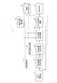
- FIG. 1 is a block diagram showing an overall configuration of a traffic light detection apparatus 1 according to the first embodiment.
- FIG. 2 is a block diagram showing a detailed configuration of the synchronized image generation circuit 24 of FIG.
- FIG. 3 is a diagram illustrating an example of Bayer conversion processing from a Bayer image to a color image.
- FIG. 3A illustrates a Bayer image when a red light is detected
- FIG. 3B illustrates FIG.
- FIG. 3C shows a Bayer image when green light is detected
- FIG. 3D shows a color image obtained by converting the Bayer image shown in FIG. Show.
- FIG. 3A illustrates a Bayer image when a red light is detected
- FIG. 3B illustrates FIG.
- FIG. 3C shows a Bayer image when green light is detected
- FIG. 3D shows a color image obtained by converting the Bayer image shown in FIG
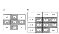
- FIG. 4 shows an example of a grayscale image when a color image is grayscale converted using the general weighting count shown in (Equation 1)
- FIG. 4 (a) is a diagram of FIG. 3 (c).
- FIG. 4B shows a grayscale image obtained by converting the color image
- FIG. 4B shows a grayscale image obtained by converting the color image shown in FIG.
- FIG. 5 shows an example of a grayscale image when a color image is grayscale converted using the grayscale conversion formula shown in (Equation 2)
- FIG. 5 (a) shows the color image of FIG. 3 (c).
- 5B is a gray image obtained by converting the color image of FIG. 3D.
- FIG. 3D is a gray image obtained by converting the color image of FIG. 3D.
- FIG. 6 is a flowchart showing an example of a traffic signal detection method using the traffic signal detection apparatus 1 of FIG.
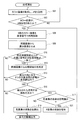
- FIG. 7 is a flowchart showing an example of a traffic light detection method according to the second embodiment.
- FIG. 8 is a block diagram showing the overall configuration of the traffic light detection apparatus 2 according to the third embodiment.
- FIG. 9 is a flowchart showing an example of a traffic light detection method using the traffic light detection device 2 of FIG.
- FIG. 10A shows a Bayer array of Bayer images
- FIGS. 10B to 10D show images extracted by dividing the pixels in FIG. 10A for each color.
- the traffic light detection device 1 is mounted on a vehicle, and a color imaging unit 11 that captures a color image by capturing the surroundings of the vehicle, and an image processing unit that detects a traffic signal using the color image acquired by the color imaging unit 11. 12, a vehicle position detection unit 13, and a map database 14.
- the color imaging unit 11 is a digital camera including a solid-state imaging device (image sensor), for example, a CCD or a CMOS, and acquires a color image that can be processed.
- the color imaging unit 11 repeats at predetermined time intervals, for example, images the front of the vehicle and acquires a plurality of continuous color images.
- the color imaging unit 11 performs imaging a plurality of times during one AC cycle of the system power supply supplied to the traffic signal.
- the color imaging unit 11 can capture the lighting of one or more traffic signals existing in front of the vehicle in each color image.
- the image sensor has a sensitivity that can detect at least a traffic signal light at a distance necessary for the vehicle to stop.
- the image processing unit 12 receives the color image data acquired by the color imaging unit 11, and detects the position of the traffic signal on the image and the lighting color of the traffic signal included in the color image.
- the detected traffic signal information is transferred to another processing arithmetic device (vehicle CPU 16) mounted on the vehicle including, for example, a controller for realizing automatic driving of the vehicle.
- vehicle CPU 16 processing arithmetic device mounted on the vehicle including, for example, a controller for realizing automatic driving of the vehicle.
- the image processing unit 12 includes, for example, a microcontroller including a CPU, a memory, and an input / output unit, and configures a plurality of information processing circuits included in the traffic light detection device 1 by executing a computer program installed in advance.
- the image processing unit 12 repeatedly executes a series of information processing cycles (including gray scale conversion processing and power synchronization processing) for detecting traffic signals from color images for each of a plurality of continuous color images.
- the image processing unit 12 may also be used as an ECU used for other control relating to the vehicle.
- the plurality of information processing circuits configured by the image processing unit 12 include a grayscale image generation circuit 21 and a traffic light detection circuit 22.
- the gray image generation circuit 21 converts the color image into a gray image having gray levels. In other words, a grayscale conversion process is executed on the color image to generate a grayscale image consisting only of luminance (including lightness) information.
- each color element of red (R), green (G), and blue (B) A certain weight is given to the value.
- R, G, and B A certain weight is given to the value.
- each color element of the color image is associated with the gray scale.
- the weighting coefficient (NTSC Coefficients) shown in (Expression 1) is well known as a general gray scale conversion expression.
- Y indicates the luminance in the grayscale image
- R, G, and B indicate the R element value, the G element value, and the B element value in the color image.
- the detection distance or the detection sensitivity varies depending on the lamp color. For example, there may be a case where a green light far from the vehicle can be detected, but a red light nearby cannot be detected from the vehicle.
- each color element of the color image is associated with a gray level so that the luminance difference between the red light of the traffic signal and the green light of the traffic signal in the gray image is within a predetermined value. Details of the gray scale conversion processing will be described later with reference to FIGS. 4 and 5.
- the traffic signal detection circuit 22 detects the position on the traffic signal image and the traffic color of the traffic signal using the grayscale image and the color image.
- the traffic light detection circuit 22 includes a synchronous image generation circuit 24, a lamp position determination circuit 25, and a lamp color determination circuit 26.
- the synchronous image generation circuit 24 first acquires frequency information of the system power supply around the vehicle including the traffic signal. Then, using the frequency information of the system power supply, a synchronous pixel whose luminance changes in synchronization with the AC power cycle is extracted from the grayscale image. And the synchronous image which consists of the extracted synchronous pixel is produced
- the synchronous image generation circuit 24 includes a reference signal generation unit, a multiplication unit 30, and an average image generation unit 31.
- the reference signal generation unit uses the frequency information of the system power supply (commercial power supply) to generate the reference signal 29 synchronized with the phase of the power supplied to the traffic signal device.
- the multiplication unit 30 multiplies the luminance signal of each pixel of the frame 28 (grayscale image) and the reference signal 29.
- the multiplication unit 30 performs the multiplication process described above for each of the plurality of frames 28 (grayscale images) stored simultaneously in the memory.
- the average image generation unit 31 calculates an average value of the multiplication results for each frame by the multiplication unit 30 and outputs the average value as a synchronization image including synchronization pixels.
- the power supplied to the traffic signal is AC power that is full-wave rectified from the power of the commercial power supply.
- the luminance of a signal lamp that is turned on when supplied with power from a commercial power supply changes in the same cycle as the cycle of full-wave rectified AC power (for example, 100 Hz). Therefore, synchronized pixels whose luminance changes in synchronization with the AC cycle of power supplied to the traffic signal can be extracted from the frame 28 (grayscale image).
- the lamp position determination circuit 25 detects a signal lamp that is lit, that is, a lamp, from the synchronized pixels. Specifically, a synchronous pixel having a luminance higher than a predetermined luminance threshold is determined as a lamp, and the position of the lamp on the grayscale image is detected.
- the lamp color determination circuit 26 receives the color image acquired by the color imaging unit 11, and uses the color image to determine the lamp color of the traffic light at the position of the lamp on the grayscale image determined by the lamp position determination circuit 25. To detect.
- the vehicle position detector 13 detects the current position and the current posture of the vehicle.
- the detection method is not particularly limited, and a known method can be used.
- a current position and a current posture of the vehicle may be detected by receiving a positioning signal such as a GPS signal.
- the position and orientation may be detected from the landmark detected from the color image and the position of the landmark on the map.
- self-position estimation based on the amount of movement (odometry) of the vehicle from the yaw rate and wheel speed of the vehicle may be used.
- the map database 14 stores data indicating the shape of the road on which the vehicle can travel and the position of a traffic signal provided on the road.
- the lighting position determination circuit 25 uses a data indicating the current position and current posture of the vehicle on the map and the position of the traffic signal on the map, and is a color image, a gray image, or a synchronized image (simply called an image).
- the search range where the traffic signal is predicted to be captured is set.
- the lamp position determination circuit 25 can determine, from the set search range, a synchronized pixel having a luminance higher than the luminance threshold as a lamp.
- FIG. 3A shows a Bayer image when a red light is imaged by the color imaging unit 11 with the minimum unit of four pixels.
- the pixels receiving light have a value of 1, and the pixels not receiving light are The value is shown as 0.
- FIG. 3B shows an RGB color image obtained by Bayer conversion of the Bayer image of FIG. 3A, and only pixels having values after conversion are illustrated.
- FIG. 3C shows a Bayer image when a green light is imaged by the color imaging unit 11 with four pixels as a minimum unit.
- FIG. 3D shows an RGB color image obtained by performing Bayer conversion of the Bayer image of FIG. 3C, and only the pixels having values after conversion are illustrated.
- the image sensor displays a Bayer image having a Bayer array of one red (R), two green (G1, G2), and one blue (B) as a unit. Generate.
- red (R) only the pixels to which red (R) is assigned receive light as shown in FIG.
- green (G1, G2) and blue (B) are assigned receive light.
- the image engine included in the color imaging unit 11 converts the charge received by each pixel into a luminance value, reads a Bayer image, performs Bayer conversion on the Bayer image, and FIGS. 3B and 3D.
- an RGB color image is generated.
- the numerical values shown in the frames of FIGS. 3B and 3D indicate (R element value, G element value, B element value) of each pixel.
- a process of complementing RGB components that cannot be received by each pixel from eight neighboring pixels in the Bayer image is performed. For example, for a pixel assigned with red (R) (FIG. 3A), G and B components that cannot receive light are complemented from eight pixels adjacent to the pixel.
- the pixel (1) in FIG. 3B corresponds to the pixel assigned with red (R) (FIG. 3A).
- R red
- FIG. 3A since the pixels to which green (G) and blue (B) are assigned do not receive light, the pixel of (1) in FIG. )
- the R component and B component that cannot receive light are complemented from the eight pixels adjacent to the pixel.
- the pixel (2) in FIG. 3 (b) corresponds to the pixel (FIG. 3 (a)) to which green (G1) is assigned.
- the R pixel in FIG. 3A receives light, but the adjacent R component pixel does not receive light
- the pixel in (2) in FIG. 3B is (0.5, 0, 0). The same applies to complementation of pixels assigned with green (G2) and blue (B).
- FIG. 4 shows an example of a grayscale image obtained by performing gray scale conversion on an RGB color image using a general weighting coefficient shown in (Equation 1).
- 4A is a grayscale image obtained by converting the RGB color image of FIG. 3C
- FIG. 4B is a grayscale image obtained by converting the RGB color image of FIG. 3D.
- the numerical values shown in each frame in FIGS. 4A and 4B indicate the luminance of each pixel.
- the luminance threshold is set to 0.15
- the hatched pixels in FIGS. 4A and 4B exceed the luminance threshold, and thus are detected as lights. Comparing FIG. 4A and FIG. 4B, the luminance of the red lamp in the grayscale image is smaller than that of the green lamp.
- the range of pixels detected as a lamp is also narrower for red lamps than for green lamps.
- Equation 1 the luminance value of each pixel in the grayscale image and the range (area) of the pixels detected as the light according to the light color. Large variations occur.
- the grayscale image generation circuit 21 of the present embodiment performs grayscale conversion of a color image using the grayscale conversion formula shown in (Formula 2).
- (Equation 2) differs from the general gray scale conversion equation (Equation 1) in weighting coefficients. The red (R) coefficient increases and the green (G) and blue (B) coefficients decrease.
- FIG. 5 shows a grayscale image obtained by performing gray scale conversion on the RGB color image of FIGS. 3C and 3D using the gray scale conversion formula shown in (Expression 2).
- the numerical values shown in each frame in FIGS. 5A and 5B indicate the luminance of each pixel.
- the luminance threshold is set to 0.15 in the same manner as in FIG. 4, the hatched pixels in FIGS. 5A and 5B exceed the luminance threshold, and thus are detected as lights. 4 is compared with FIG. 5, the difference between the luminance of the red lamp and the luminance of the green lamp in the grayscale image is smaller in FIG. 5 than in FIG. Furthermore, the difference between the pixel range detected as a green lamp and the pixel range detected as a red lamp is also smaller in FIG. 5 than in FIG. 4.
- (Equation 2) instead of (Equation 1), the variation of the luminance value of each pixel in the grayscale image and the range (area) of the pixels detected as the lighting according to the light color. Variations can be reduced.
- the grayscale image generation circuit 21 associates each color element of the RGB color image with the grayscale so that the luminance difference between the red light of the traffic light and the green light of the traffic light is within a predetermined value in the grayscale image. .
- each color element of the RGB color image can be associated with the grayscale.
- step S01 the color imaging unit 11 continuously acquires color images.
- the acquired plurality of color images are stored in the memory.
- the process proceeds to step S05, and the grayscale image generation circuit 21 uses (Expression 2).
- each color image is converted into a grayscale image by gray scale conversion.
- the six converted gray images are transferred to the memory again.
- the process proceeds to step S07, and the synchronous image generation circuit 24 includes the synchronous pixels whose luminance changes in synchronization with the AC power cycle by performing the processing shown in FIG. 2 on the six gray images. Generate synchronized images.
- the lighting position determination circuit 25 determines whether or not the position information of the traffic signal coincides with a pixel group composed of synchronous pixels having a luminance higher than a predetermined luminance threshold. Specifically, first, a synchronous pixel having a luminance higher than a predetermined luminance threshold is determined as a lamp, and the position of the lamp on the image is detected. Then, the search range on the image where the traffic signal is predicted to be captured is set from the position and posture of the vehicle and the position information of the traffic signal.
- the position of the lamp on the image is included in the search range.
- the position of the lamp on the image is included in the search range (YES in S09)
- it can be determined that there is a high possibility of the lamp.
- it progresses to step S11 and the light color determination circuit 26 detects the light color of the traffic signal in the position on the image of the light determined by step S09 using a color image.
- the position of the lamp on the image is not included in the search range (NO in S09)
- it can be determined that the possibility of the lamp is low, and thus the process ends without detecting the lamp color.
- the gray image generation circuit 21 converts the color image into the gray image by associating the gray level with each color element of the color image in which the luminance difference between the red light of the traffic signal and the green light of the traffic signal is within a predetermined value. Convert. Thereby, since the detection sensitivities of green and red can be made uniform, the lighting position can be stably determined using the same luminance threshold regardless of the presentation color. Moreover, the variation in the detection distance according to the light color can be suppressed.
- the gray image generation circuit 21 associates each of the R element, G element, and B element of the color image with the gray scale. That is, the weighting coefficients of the R element, G element, and B element shown in (Expression 2) are adjusted. Thereby, the detection sensitivity between presentation colors can be aligned with high accuracy.
- the grayscale image generation circuit 21 may associate each of the R and G elements of the color image with a grayscale. That is, the third term may be deleted from the right side of (Expression 2). Thereby, the detection sensitivity between presentation colors can be accurately aligned by a simpler method.
- the gray image generation circuit 21 may associate each color element of the color image with the gray scale so that the luminance of the red light of the traffic signal and the luminance of the green light of the traffic signal in the gray image are substantially the same. Compared with the case where the luminance difference is within a predetermined value, the detection sensitivity of green and red can be made uniform, and variation in the detection distance according to the light color can be suppressed. “Substantially the same” is an expression including not only perfect identity but also substantial identity including a slight error.
- FIGS. 3 to 5 show an example in which a grayscale image is generated from a Bayer image via a color image, but a grayscale image may be generated directly from the Bayer image. Conversion processing steps are reduced, and there are effects such as reduction of calculation load and improvement of processing speed.
- the grayscale image generation circuit 21 has a luminance difference between the red light of the traffic signal and the green light of the traffic signal in the grayscale image.
- Each color element of the color image is associated with a grayscale so as to be within a predetermined value.
- the distance between the intersections is longer than the reference value, if the green light at the back intersection can be detected, the red light at the front intersection can also be detected.
- a grayscale image may be generated using the general gray scale conversion equation shown in Equation 1).
- step S13 the lighting position determination circuit 25 determines whether the distance between two intersections in the traveling direction of the vehicle is within a reference value using the vehicle position and map information. If it is within the reference value (YES in S13), there is a possibility that the green light on the back side may be erroneously detected as the presentation color of the traffic signal on the near side, so the process proceeds to step S15, and the light detected in step S11 is detected. Determine whether the color is green.
- step S15 When the lamp is green (YES in step S15), it is necessary to suppress non-detection of the red lamp on the near side. Therefore, the process proceeds to step S17, where it is determined whether or not the weighting coefficient of each color element is the value (initial value) shown in (Equation 1). If it is the initial value (YES in S17), the weighting of the R element is determined. The coefficient is increased (step S21), the process returns to step S05, and grayscale conversion is performed again. If it is not the initial value (NO in S17), that is, if it has already been increased, the weighting coefficient of the R element is returned to the initial value shown in (Equation 1) (step S19).
- the grayscale image generation circuit 21 increases the detection sensitivity of the red light. Then, the color image is converted again into a grayscale image. Thereby, it is possible to change the association between each color element of the color image and the gray scale so that the luminance difference between the red light of the traffic signal and the green light of the traffic signal in the gray image is within a predetermined value. And since the lighting position determination circuit 25 detects a traffic signal from the re-converted grayscale image, even if a red light of a nearby traffic light is lit and non-detection occurs, It is possible to detect the red lights of the traffic lights.
- the present invention is not limited to this, and may be applied to all cases in which a green lamp is detected. Further, the present invention may be applied not only when a green lamp is detected and a red lamp is not detected, but also when the detected signal lamp includes a red lamp.
- synchronization processing is performed on the Bayer image shown in FIG. That is, a synchronous pixel whose luminance changes in synchronization with the AC alternating current cycle is extracted from the Bayer image to generate a synchronous image.
- the grayscale image generation circuit 21 performs Bayer conversion on the synchronized image, and performs grayscale conversion using (Expression 2).
- FIG. 8 shows a configuration example of the traffic light detection apparatus 2 according to the third embodiment.
- the arrangement of the synchronous image generation circuit 24 and the grayscale image generation circuit 21 is switched.
- Bayer conversion is not performed, and the Bayer image is transferred to the synchronous image generation circuit 24.
- the grayscale image generation circuit 21 performs Bayer conversion on the synchronized image, generates an RGB color image of the synchronized image, and performs grayscale conversion.
- the lamp color determination circuit 26 determines the lamp color using a synchronized image instead of a color image.
- Other configurations are the same as those in FIG.
- FIG. 9 shows an example of a traffic signal detection method using the traffic signal detection device 2 of FIG.
- Steps S01 and S03 are the same processing as in FIG. Thereafter, instead of step S07 in FIG. 6, the process proceeds to step S08, and the synchronous image generation circuit 24 performs the processing shown in FIG. 2 on the six color images in synchronization with the AC AC cycle.
- a synchronous image composed of synchronous pixels whose luminance changes is generated.
- step S06 the grayscale image generation circuit 21 performs Bayer conversion on the synchronization image to generate an RGB color image of the synchronization image, and then uses (Equation 2) to perform synchronization. Convert grayscale image to grayscale image. The converted gray image is transferred to the memory again.
- step S10 instead of step S09 in FIG. 6, the lighting position determination circuit 25 determines whether or not the traffic signal position information matches a pixel group including synchronous pixels having a luminance higher than a predetermined luminance threshold value. Determine whether.
- step S11 in FIG. 6 the process proceeds to step S12, and the lamp color determination circuit 26 detects the lamp color of the traffic light at the lamp position on the image determined in step S10 using the synchronization image. . Thereafter, steps S13 to S21 are the same processing as in FIG.
- FIGS. 10B to 10D show images (41R, 41G, 41B) for each color element extracted by dividing FIG. 10A.
- the color imaging unit 11 generates a Bayer image 41 in which an R element, a G element, or a B element is assigned to each pixel of the image sensor.
- the color imaging unit 11 generates an R image 41R, a G image 41G, and a B image 41B obtained by extracting each of the R element, the G element, and the B element from the Bayer image 41.
- the gray image generation circuit 21 converts each of the R image, the G image, and the B image into a gray image.
- each of the R image 41R, the G image 41G, and the B image 41B is multiplied by a weighting coefficient shown in (Expression 2) to form a grayscale image for each color.
- the synchronized image generation circuit 24 extracts a synchronized pixel from each of the grayscale images and generates a synchronized image.
- the lighting position determination circuit 25 detects the lighting of the traffic signal from each of the synchronized images.
- FIG. 7 shows an example in which the weighting coefficient of the R element is increased (step S21), but the present invention is not limited to this.
- the weighting coefficients of the G element and B element may be decreased. Thereby, it is possible to change the association between each color element of the color image and the gray scale so that the luminance difference between the red light of the traffic signal and the green light of the traffic signal in the gray image is within a predetermined value.
Landscapes
- Physics & Mathematics (AREA)
- General Physics & Mathematics (AREA)
- Engineering & Computer Science (AREA)
- Theoretical Computer Science (AREA)
- Traffic Control Systems (AREA)
- Image Processing (AREA)
- Image Analysis (AREA)
Abstract
信号機検出装置は、車両に搭載されたカラー撮像部でカラー画像を取得し、カラー画像を、濃淡画像における交通信号機の赤色灯火と交通信号機の緑色灯火との輝度差を所定値以内とするカラー画像の各色要素に対する濃淡階調の対応付けによって、濃淡画像へ変換し、濃淡画像から交通信号機の灯火を検出する。
Description
本発明は、信号機検出装置及び信号機検出方法に関するものである。
従来から、信号機の外形をパターン比較により特定した上で、信号機の灯火位置を濃淡画像の輝度から判断する技術が知られている(特許文献1参照)。
カラー画像に対する一般的なグレースケール変換処理を行って濃淡画像を生成した場合、輝度が同じ対象物であっても、赤色の対象物の方が緑色の対象物に比べて輝度が小さく変換されてしまう。よって、交通信号機の灯火の提示色に係わらず一定の輝度閾値を用いて灯火を検出する場合、赤色灯火は緑色灯火に比べて検出され難かった。
本発明は、上記課題に鑑みて成されたものであり、その目的は、提示色に係わらず、同じ輝度閾値を用いて安定して灯火位置を判定できる信号機検出装置及び信号機検出方法を提供することである。
本発明の一態様に係わる信号機検出装置は、車両に搭載されたカラー撮像部でカラー画像を取得し、カラー画像を、交通信号機の赤色灯火と交通信号機の緑色灯火との輝度差を所定値以内とするカラー画像の各色要素に対する濃淡階調の対応付けによって、濃淡画像へ変換し、濃淡画像から交通信号機の灯火を検出する。
(第1実施形態)
次に、図面を参照して、本発明の実施の形態を詳細に説明する。
次に、図面を参照して、本発明の実施の形態を詳細に説明する。
図1を参照して、第1実施形態に係わる信号機検出装置1の全体構成を説明する。信号機検出装置1は、車両に搭載され、車両の周囲を撮像してカラー画像を取得するカラー撮像部11と、カラー撮像部11により取得されたカラー画像を用いて交通信号機を検出する画像処理部12と、車両位置検出部13と、地図データベース14とを備える。
カラー撮像部11は、固体撮像素子(イメージセンサ)、例えばCCD又はCMOSを備えたディジタルカメラであって、画像処理が可能なカラー画像を取得する。カラー撮像部11は、所定の時間間隔で繰り返し、例えば、車両の前方を撮像して、連続する複数のカラー画像を取得する。カラー撮像部11は、交通信号機に供給される系統電源の1交流周期の間に、複数回の撮像を行う。カラー撮像部11は、各カラー画像に、車両の前方に存在する1又は2以上の交通信号機の灯火を撮像することができる。イメージセンサは、少なくとも、交通信号機の灯火を、車両が停止するために必要な距離で検出することができる程度の感度を有する。
画像処理部12は、カラー撮像部11により取得されたカラー画像のデータを受信し、カラー画像の中に含まれる交通信号機の画像上の位置、及び交通信号機の灯火色を検出する。検出された交通信号機の情報は、例えば車両の自動運転を実現するためのコントローラを含む、車両に搭載された他の処理演算装置(車両CPU16)に転送される。画像処理部12は、例えば、CPU、メモリ、及び入出力部を備えるマイクロコントローラからなり、予めインストールされたコンピュータプログラムを実行することにより、信号機検出装置1が備える複数の情報処理回路を構成する。画像処理部12は、カラー画像から交通信号機を検出する一連の情報処理サイクル(グレースケール変換処理及び電力同期処理を含む)を、連続する複数のカラー画像毎に繰り返し実行する。画像処理部12は、車両にかかわる他の制御に用いるECUと兼用してもよい。
画像処理部12により構成される複数の情報処理回路には、濃淡画像生成回路21と、信号機検出回路22とが含まれる。
濃淡画像生成回路21は、カラー画像を濃淡階調からなる濃淡画像へ変換する。換言すれば、カラー画像に対してグレースケール変換処理を実行して、輝度(明度を含む)情報のみから成る濃淡画像を生成する。
人間の目では、色合いによって明るさの感じ方が違う。NTSC加重平均法では、人間の目に違和感の無いグレースケール変換を行うために、例えば、(式1)に示すように、赤色(R)、緑色(G)、青色(B)の各色要素の値に一定の重みを付している。これにより、カラー画像の各色要素と濃淡階調とを対応付けている。(式1)に示す重み付けの係数(NTSC Coefficients)は、一般的なグレースケール変換式として良く知られている。(式1)において、Yは、濃淡画像における輝度を示し、R,G,Bは、カラー画像におけるR要素値、G要素値、B要素値を示す。
Y=0.299×R+0.587×G+0.114×B ・・・(式1)
しかし、一般的なグレースケール変換式を交通信号機の灯火検出に用いた場合、交通信号機の緑色灯火に比べ、赤色灯火の輝度が小さく変換されてしまう。このため、灯火色に応じて検出距離又は検出感度にバラツキが生じてしまう。例えば、車両から遠方の緑色灯火を検出できるが、車両から近傍の赤色灯火を検出できない場合がある。
そこで、本実施形態では、交通信号機の灯火色に特化したグレースケール変換式を用いることで、灯火色による検知距離のバラツキを抑制する。具体的には、濃淡画像における交通信号機の赤色灯火と交通信号機の緑色灯火との輝度差が所定値以内となるように、カラー画像の各色要素を濃淡階調に対応付ける。グレースケール変換処理の詳細については、図4及び図5を参照して後述する。
信号機検出回路22は、濃淡画像及びカラー画像を用いて、交通信号機の画像上の位置及び交通信号機の灯火色を検出する。信号機検出回路22は、同期画像生成回路24と、灯火位置判定回路25と、灯火色判定回路26とを備える。
同期画像生成回路24は、先ず、交通信号機を含む車両周辺における系統電源の周波数情報を取得する。そして、系統電源の周波数情報を用いて、濃淡画像の中から、電力の交流周期と同期して輝度が変化する同期画素を抽出する。そして、抽出された同期画素からなる同期画像を生成する。具体的に、図2に示すように、同期画像生成回路24は、基準信号生成部と、乗算部30と、平均画像生成部31とを備える。基準信号生成部は、系統電源(商用電源)の周波数情報を用いて、交通信号機に供給される電力の位相に同期した基準信号29を生成する。そして、乗算部30は、フレーム28(濃淡画像)の各画素の輝度信号と基準信号29とを乗算する。乗算部30は、メモリに同時に記憶されている複数のフレーム28(濃淡画像)の各々について、上記した乗算処理を実施する。平均画像生成部31は、乗算部30によるフレーム毎の乗算結果の平均値を求め、同期画素からなる同期画像として出力する。
交通信号機に供給される電力は、商用電源の電力を全波整流した交流電力である。商用電源から電力の供給を受けて点灯する信号灯の輝度は、全波整流した交流電力の周期(例えば、100Hz)と同じ周期で変化する。そこで、交通信号機に供給される電力の交流周期に同期して輝度が変化する同期画素をフレーム28(濃淡画像)の中から抽出することができる。
灯火位置判定回路25(灯火検出回路)は、同期画素の中から点灯中の信号灯、即ち灯火を検出する。具体的には、予め定めた輝度閾値よりも輝度が高い同期画素を灯火として判定して、濃淡画像上の灯火の位置を検出する。
灯火色判定回路26は、カラー撮像部11により取得されたカラー画像を受信し、カラー画像を用いて、灯火位置判定回路25により判定された濃淡画像上の灯火の位置における交通信号機の灯火色を検出する。
車両位置検出部13は、車両の現在位置及び現在姿勢を検出する。検出方法は特に問わず、既知の方法を用いることができる。例えば、GPS信号などの測位信号を受信して車両の現在位置及び現在姿勢を検出してもよい。或いは、カラー画像から検出されるランドマーク及びこのランドマークの地図上の位置から、位置及び姿勢を検出してもよい。更に、測位信号を受信できない場合、或いは、ランドマークが検出できない場合、車両のヨーレイト及び車輪速から車両の移動量(オドメトリ)による自己位置推定を用いてもよい。
地図データベース14には、車両が走行可能な道路の形状及び道路上に設けられた交通信号機の位置を示すデータが格納されている。灯火位置判定回路25は、地図上における車両の現在位置及び現在姿勢、及び地図上における交通信号機の位置を示すデータを用いて、カラー画像、濃淡画像、或いは同期画像(単に、画像と呼ぶ。)上において、交通信号機が写ることが予測される検索範囲を設定する。灯火位置判定回路25は、設定された検索範囲の中から、輝度閾値よりも輝度が高い同期画素を灯火として判定することができる。
図3を参照して、ベイヤー画像からRGBカラー画像へのベイヤー変換処理を説明する。図3(a)は、赤色灯火をカラー撮像部11が最小単位の4画素で撮像した時のベイヤー画像を示しており、受光している画素は、値を1とし、受光していない画素は、値を0として示している。図示していないが、この4画素の周囲の画素は、受光していない画素であり、値は0である。図3(b)は図3(a)のベイヤー画像をベイヤー変換したRGBカラー画像を示しており、変換後に値のある画素のみ図示している。図3(c)は緑色灯火をカラー撮像部11が最小単位の4画素で撮像した時のベイヤー画像を示しており、受光している画素は、値を1とし、受光していない画素は、値を0として示している。図示していないが、この4画素の周囲の画素は、受光していない画素であり、値は0である。図3(d)は図3(c)のベイヤー画像をベイヤー変換したRGBカラー画像を示しており、変換後に値のある画素のみ図示している。
イメージセンサは、図3(a)及び(c)に示すように、1つの赤色(R)、2つの緑色(G1、G2)及び1つの青色(B)のベイヤー配列を単位とするベイヤー画像を生成する。赤色灯火の場合、図3(a)のように、赤色(R)が割り当てられた画素のみが光を受光する。緑色灯火の場合、図3(c)のように、緑色(G1、G2)及び青色(B)が割り当てられた画素のみが光を受光する。
そして、カラー撮像部11が備える画像エンジンは、各画素で受光した電荷を輝度値に変換してベイヤー画像を読み出し、このベイヤー画像に対してベイヤー変換を行い、図3(b)及び(d)に示すように、RGBカラー画像を生成する。図3(b)及び(d)の枠内に示す数値は、各画素の(R要素値、G要素値、B要素値)を示す。ベイヤー変換では、ベイヤー画像において、各画素で受光できないRGB成分を周囲に隣接する8つの画素から補完する処理を行う。例えば、赤色(R)が割り当てられた画素(図3(a))に対して、受光できないG成分及びB成分を当該画素に隣接する8つの画素からそれぞれ補完する。これにより、図3(b)に示すRGBカラー画像を得ることができる。図3(b)の(1)の画素が、赤色(R)が割り当てられた画素(図3(a))に対応している。図3(a)の場合、緑色(G)及び青色(B)が割り当てられた画素は光を受光していないので、図3(b)の(1)の画素は、(1,0,0)となる。緑色(G1)が割り当てられた画素に対して、受光できないR成分及びB成分を当該画素に隣接する8つの画素からそれぞれ補完する。図3(b)の(2)の画素が、緑色(G1)が割り当てられた画素(図3(a))に対応している。図3(a)のR画素は受光しているが、隣接するR成分の画素は光を受光していないので、図3(b)の(2)の画素は、(0.5,0,0)となる。緑色(G2)及び青色(B)が割り当てられた画素の補完についても同様である。
図4は、RGBカラー画像を、(式1)に示した一般的な重み付けの係数を用いてグレースケール変換した濃淡画像の例を示す。図4(a)は、図3(c)のRGBカラー画像を変換した濃淡画像であり、図4(b)は、図3(d)のRGBカラー画像を変換した濃淡画像である。図4(a)及び(b)の各枠内に示す数値は、各画素の輝度を示す。輝度閾値を0.15とした場合、図4(a)及び(b)のハッチングを付した画素が、輝度閾値を超えるため、灯火として検出される。図4(a)と図4(b)とを比較すると、濃淡画像における赤色灯火の輝度は、緑色灯火の輝度に比べて小さい。更に、灯火として検出される画素の範囲も、緑色灯火に比べて、赤色灯火は狭くなる。このように、(式1)に示す一般的なグレースケール変換式を用いた場合、灯火色に応じて、濃淡画像における各画素の輝度値、及び灯火として検出される画素の範囲(面積)に大きなバラツキが生じる。
これに対して、本実施形態の濃淡画像生成回路21は、(式2)に示すグレースケール変換式を用いて、カラー画像をグレースケール変換する。(式2)は、一般的なグレースケール変換式(式1)と比べて、重み付けの係数が相違する。赤色(R)の係数が増加し、緑色(G)及び青色(B)の係数が減少している。
Y=0.4×R+0.5×G+0.1×B ・・・(式2)
図5は、図3(c)及び図3(d)のRGBカラー画像を、(式2)に示したグレースケール変換式を用いてグレースケール変換した濃淡画像を示す。図5(a)及び(b)の各枠内に示す数値は、各画素の輝度を示す。図4と同様にして輝度閾値を0.15とした場合、図5(a)及び(b)のハッチングを付した画素が、輝度閾値を超えるため、灯火として検出される。図4と図5とを比較すると、濃淡画像における赤色灯火の輝度と緑色灯火の輝度との差は、図4よりも図5の方が小さい。更に、緑色灯火として検出される画素の範囲と、赤色灯火として検出される画素の範囲との差も、図4よりも図5の方が小さい。このように、(式1)の代わりに(式2)を用いることによって、灯火色に応じた、濃淡画像における各画素の輝度値のバラツキ、及び灯火として検出される画素の範囲(面積)のバラツキを小さくすることができる。
このように、濃淡画像生成回路21は、濃淡画像における交通信号機の赤色灯火と交通信号機の緑色灯火との輝度差が所定値以内となるように、RGBカラー画像の各色要素を濃淡階調に対応付ける。各色要素の重み付けの係数を調整することにより、RGBカラー画像の各色要素を濃淡階調に対応付けることができる。これにより、交通信号機の灯火色に特化したグレースケール変換式(式2)を用いて、灯火色による検知距離のバラツキを抑制することができる。
図6のフローチャートを参照して、図1の信号機検出装置1を用いた信号機検出方法の一例を説明する。
先ず、ステップS01において、カラー撮像部11は、カラー画像を連続して取得する。取得した複数のカラー画像は、メモリに記憶される。交通信号機に供給される系統電源の1交流周期の間に、6枚のカラー画像が取得された場合(S03でYES)、ステップS05に進み、濃淡画像生成回路21は、(式2)を用いて、各カラー画像を濃淡画像へグレースケール変換する。変換した6枚の濃淡画像は、再びメモリに転送される。
次に、ステップS07に進み、同期画像生成回路24は、6枚の濃淡画像に対して、図2に示した処理を施して、電力の交流周期と同期して輝度が変化する同期画素からなる同期画像を生成する。ステップS09に進み、灯火位置判定回路25は、交通信号機の位置情報と、予め定めた輝度閾値よりも輝度が高い同期画素からなる画素群とが合致するか否かを判断する。具体的には、先ず、予め定めた輝度閾値よりも輝度が高い同期画素を灯火として判定して、灯火の画像上の位置を検出する。そして、車両の位置及び姿勢、及び交通信号機の位置情報から、交通信号機が撮像されることが予測される画像上の検索範囲を設定する。画像上の灯火の位置が検索範囲に含まれているか否かを判断する。画像上の灯火の位置が検索範囲に含まれている場合(S09でYES)、灯火である可能性が高いと判断できる。そこで、ステップS11に進み、灯火色判定回路26は、カラー画像を用いて、ステップS09で判定された灯火の画像上の位置における交通信号機の灯火色を検出する。一方、画像上の灯火の位置が検索範囲に含まれていない場合(S09でNO)、灯火である可能性は低いと判断できるので、灯火色を検出することなく、処理は終了する。
以上説明したように、第1実施形態によれば、以下の作用効果が得られる。
カラー画像に対する一般的なグレースケール変換処理を行って濃淡画像を生成した場合、輝度が同じ対象物であっても、赤色の対象物の方が緑色の対象物に比べて輝度が小さく変換されてしまう。よって、提示色に係わらず一定の輝度閾値を用いた場合、緑色に比べて赤色が検出されにくかった。そこで、濃淡画像生成回路21は、交通信号機の赤色灯火と交通信号機の緑色灯火との輝度差が所定値以内となるカラー画像の各色要素に対する濃淡階調の対応付けによって、カラー画像を濃淡画像へ変換する。これにより、緑色と赤色の検出感度を揃えることができるので、提示色に係わらず、同じ輝度閾値を用いて安定して灯火位置を判定することができる。また、灯火色に応じた検出距離のバラツキを抑制することができる。
濃淡画像生成回路21は、カラー画像のR要素、G要素及びB要素の各々を濃淡階調に対応付ける。即ち、(式2)に示したR要素、G要素及びB要素の各々の重み付けの係数を調整している。これにより、提示色間での検出感度を精度良く揃えることができる。
なお、濃淡画像生成回路21は、カラー画像のR要素及びG要素の各々を濃淡階調に対応付けてもよい。即ち、(式2)の右辺から、第3項を削除してもよい。これにより、より簡易な方法で提示色間での検出感度を精度良く揃えることができる。
濃淡画像生成回路21は、濃淡画像における交通信号機の赤色灯火の輝度と交通信号機の緑色灯火の輝度が略同一となるように、カラー画像の各色要素を濃淡階調に対応付けてもよい。輝度差が所定値以内とする場合に比べて、更に、緑色と赤色の検出感度を揃えて、灯火色に応じた検出距離のバラツキを抑制することができる。「略同一」とは、完全な同一のみならず、微少な誤差を含んだ実質的な同一をも含む表現である。
図3~図5には、べイヤー画像からカラー画像を介して濃淡画像を生成する例を示したが、べイヤー画像から直接、濃淡画像を生成しても構わない。変換処理工程が削減され、演算負荷の軽減、処理速度の向上などの効果がある。
(第1変形例)
車両の進行方向に在る2つの交差点間の距離が基準値以内であると、画像内に写る交通信号機がどちらの交差点に在るのか判別できない場合がある。この場合、緑色よりも赤色の検出感度が低いと、手前側の交差点の提示色を誤って緑色と判定してしまうおそれがある。具体的には、奥側の交差点の緑色灯火を検出できたが、手前側の交差点の赤灯火を検出できなかった場合、奥側の緑色灯火を手前側の交通信号機の提示色として誤検出してしまう可能性がある。なぜなら、画像内の交通信号機の位置が近い場合には交通信号機の地図上の位置を特定することが難しいからである。
車両の進行方向に在る2つの交差点間の距離が基準値以内であると、画像内に写る交通信号機がどちらの交差点に在るのか判別できない場合がある。この場合、緑色よりも赤色の検出感度が低いと、手前側の交差点の提示色を誤って緑色と判定してしまうおそれがある。具体的には、奥側の交差点の緑色灯火を検出できたが、手前側の交差点の赤灯火を検出できなかった場合、奥側の緑色灯火を手前側の交通信号機の提示色として誤検出してしまう可能性がある。なぜなら、画像内の交通信号機の位置が近い場合には交通信号機の地図上の位置を特定することが難しいからである。
そこで、車両の進行方向に在る2つの交差点間の距離が基準値以内である場合に、濃淡画像生成回路21は、濃淡画像における交通信号機の赤色灯火と交通信号機の緑色灯火との輝度差が所定値以内となるように、カラー画像の各色要素を濃淡階調に対応付ける。交差点間の距離が基準値よりも長い場合には、奥側の交差点の緑色灯火を検出できた場合には、手前側の交差点の赤灯火も検出できるため、濃淡画像生成回路21は、例えば(式1)に示した一般的なグレースケール変換式を用いて、濃淡画像を生成すればよい。
これにより、奥側の緑色灯火を手前側の交通信号機の提示色として誤検出してしまうこと、即ち、手前側の赤色灯火の見落としを抑制することができる。
(第2実施形態)
本実施形態では、図7を参照して、車両の進行方向に在る2つの交差点間の距離が基準値以内であり、且つ、緑色灯火を検出した場合、赤色灯火と緑色灯火の輝度差が小さくなるように、カラー画像の各色要素に対する濃淡階調の対応付けを変更する例を説明する。
本実施形態では、図7を参照して、車両の進行方向に在る2つの交差点間の距離が基準値以内であり、且つ、緑色灯火を検出した場合、赤色灯火と緑色灯火の輝度差が小さくなるように、カラー画像の各色要素に対する濃淡階調の対応付けを変更する例を説明する。
図7のステップS01~S11の処理は、図6のステップS01~S11と同じであり、説明を省略する。なお、本実施形態では、ステップS05、S07でのグレースケール変換を(式1)を用いている。ステップS13に進み、灯火位置判定回路25は、車両の位置及び地図情報を用いて、車両の進行方向に在る2つの交差点間の距離が基準値以内であるか否かを判断する。基準値以内である場合(S13でYES)、奥側の緑色灯火を手前側の交通信号機の提示色として誤検出してしまうおそれがあるため、ステップS15へ進み、ステップS11で検出された灯火が緑色であるか否かを判断する。灯火が緑色である場合(ステップS15でYES)、手前側の赤色灯火の非検出を抑制する必要がある。そこで、ステップS17に進み、各色要素の重み付けの係数が(式1)に示す値(初期値)であるか否かを判断し、初期値であれば(S17でYES)、R要素の重み付けの係数を増加させ(ステップS21)、ステップS05に戻り、再度、グレースケール変換を実施する。初期値でなければ(S17でNO)、つまり既に増加させている場合、R要素の重み付けの係数を(式1)に示す初期値に戻す(ステップS19)。
このように、車両の進行方向に在る2つの交差点間の距離が基準値以内であり、且つ、緑色灯火を検出した場合、赤色灯火の非検出を抑制する必要があると判断できる。そこで、R要素の重み付けの係数を増加させ、再度、灯火の検出を実行する。それでも赤色灯火を検出できない場合(ステップS15でYES)、赤色灯火は無いと判断して、R要素の重み付けの係数を元の値に戻し(ステップS19)、処理を終了する。なお、R要素の重み付けの係数を増加させる場合、(式2)を用いても良い。
以上説明したように、車両の進行方向に在る2つの交差点間の距離が基準値以内であり、且つ、緑色灯火が検出された場合、濃淡画像生成回路21は、赤色灯火の検出感度を上げて、再度、カラー画像を濃淡画像へ変換する。これにより、濃淡画像における交通信号機の赤色灯火と交通信号機の緑色灯火との輝度差が所定値以内となるように、カラー画像の各色要素と濃淡階調との対応付けを変更することができる。そして、灯火位置判定回路25は、再変換した濃淡画像から交通信号機を検出するので、もし近傍の信号機の赤色灯火が点灯しており、非検出が発生した場合でも、再変換した濃淡画像から近傍の信号機の赤色灯火を検出することができる。これにより、赤色灯火の非検出を抑制することができる。なお、車両の進行方向に在る2つの交差点間の距離が基準値以内であるという条件を付して説明した。これに限らず、緑色灯火を検出した全ての場合に適用しても構わない。また、緑色灯火のみを検出し、赤色灯火を検出しなかった場合のみならず、検出した信号灯の中に赤色灯火が含まれている場合に適用してもよい。
(第3実施形態)
第3実施形態では、図3に示したベイヤー画像に対して、同期処理を実施する。即ち、ベイヤー画像の中から、電力の交流周期と同期して輝度が変化する同期画素を抽出して同期画像を生成する。そして、濃淡画像生成回路21は、同期画像に対して、ベイヤー変換を行い、(式2)を用いたグレースケール変換を実施する。
第3実施形態では、図3に示したベイヤー画像に対して、同期処理を実施する。即ち、ベイヤー画像の中から、電力の交流周期と同期して輝度が変化する同期画素を抽出して同期画像を生成する。そして、濃淡画像生成回路21は、同期画像に対して、ベイヤー変換を行い、(式2)を用いたグレースケール変換を実施する。
図8は、第3実施形態に係わる信号機検出装置2の構成例を示す。図1に比べて、同期画像生成回路24と濃淡画像生成回路21の配置が入れ替わっている。カラー撮像部11では、ベイヤー変換は行わず、ベイヤー画像が同期画像生成回路24に転送される。濃淡画像生成回路21は、同期画像に対してベイヤー変換を行い、同期画像のRGBカラー画像を生成した上、グレースケール変換を実施する。灯火色判定回路26は、カラー画像の代わりに、同期画像を用いて灯火色を判定している。その他の構成は、図1と同じである。
図9は、図8の信号機検出装置2を用いた信号機検出方法の一例を示す。ステップS01とS03は図6と同じ処理である。その後、図6のステップS07の代わりに、ステップS08に進み、同期画像生成回路24は、6枚のカラー画像に対して、図2に示した処理を施して、電力の交流周期と同期して輝度が変化する同期画素からなる同期画像を生成する。
図6のステップS05の代わりに、ステップS06に進み、濃淡画像生成回路21は、同期画像に対してベイヤー変換を行い同期画像のRGBカラー画像を生成した上、(式2)を用いて、同期画像を濃淡画像へグレースケール変換する。変換した濃淡画像は、再びメモリに転送される。図6のステップS09の代わりに、ステップS10に進み、灯火位置判定回路25は、交通信号機の位置情報と、予め定めた輝度閾値よりも輝度が高い同期画素からなる画素群とが合致するか否かを判断する。
画像上の灯火の位置が検索範囲に含まれている場合(S10でYES)、灯火である可能性が高いと判断できる。そこで、図6のステップS11の代わりに、ステップS12に進み、灯火色判定回路26は、同期画像を用いて、ステップS10で判定された画像上の灯火の位置における交通信号機の灯火色を検出する。その後、ステップS13~S21は図6と同じ処理である。
ベイヤー変換した後のRGBカラー画像から同期画像を生成した場合には、輝度値が低い画素では、電力の交流周期と同期しているか判別できなくなり、灯火として検出される範囲(面積)が狭くなる場合があった。濃淡画像の処理の前に、ベイヤー画像から直接、同期画像を生成ことにより、RGBカラー画像もしくは濃淡画像での灯火として検出される範囲(面積)の減少を抑制することができる。
(第4実施形態)
本実施形態では、ベイヤー画像からR要素、G要素及びB要素の各々を抽出し、それぞれの濃淡画像から灯火を検出する信号機検出装置を説明する。よって、濃淡画像は、色要素毎に生成される。
本実施形態では、ベイヤー画像からR要素、G要素及びB要素の各々を抽出し、それぞれの濃淡画像から灯火を検出する信号機検出装置を説明する。よって、濃淡画像は、色要素毎に生成される。
図10(a)はベイヤー画像41を示し、図10(b)~(d)は図10(a)を分割して抽出された色要素毎の画像(41R、41G、41B)を示す。カラー撮像部11は、イメージセンサの画素毎にR要素、G要素又はB要素を割り当てたベイヤー画像41を生成する。カラー撮像部11は、ベイヤー画像41からR要素、G要素及びB要素の各々を抽出したR画像41R、G画像41G及びB画像41Bを生成する。濃淡画像生成回路21は、R画像、G画像及びB画像の各々を濃淡画像へ変換する。このとき、R画像41R、G画像41G及びB画像41Bの各々に、(式2)に示す重み付けの係数を乗算して、色ごとの濃淡画像を形成する。同期画像生成回路24は、濃淡画像の各々から同期画素を抽出して同期画像を生成する。灯火位置判定回路25は、同期画像の各々から交通信号機の灯火を検出する。
このように、色ごとに、濃淡画像、同期画像を生成し、色ごとの画像から灯火を検出する。これにより、色の違いによる輝度の不均衡を排除することができ、赤色灯火と緑色灯火の検出感度を揃えることができる。
上記のように、本発明の実施形態を記載したが、この開示の一部をなす論述及び図面はこの発明を限定するものであると理解すべきではない。この開示から当業者には様々な代替実施の形態、実施例及び運用技術が明らかとなろう。
図7では、R要素の重み付けの係数を増加させる(ステップS21)例を示したが、これに限らない。例えば、G要素及びB要素の重み付けの係数を減少させてもよい。これにより、濃淡画像における交通信号機の赤色灯火と交通信号機の緑色灯火との輝度差が所定値以内となるように、カラー画像の各色要素と濃淡階調との対応付けを変更することができる。
1、2 信号機検出装置
11 カラー撮像部
13 車両位置検出部
14 地図データベース
21 濃淡画像生成回路
25 灯火位置判定回路(灯火検出回路)
26 灯火色判定回路
28 フレーム(画像)
41 ベイヤー画像
11 カラー撮像部
13 車両位置検出部
14 地図データベース
21 濃淡画像生成回路
25 灯火位置判定回路(灯火検出回路)
26 灯火色判定回路
28 フレーム(画像)
41 ベイヤー画像
Claims (8)
- 車両に搭載され、交通信号機を含むカラー画像を取得するカラー撮像部と、
前記カラー画像を濃淡画像へ変換する濃淡画像生成回路と、
前記濃淡画像から前記交通信号機の灯火を検出する灯火検出回路と、を備え、
前記濃淡画像生成回路は、前記交通信号機の赤色灯火と前記交通信号機の緑色灯火との輝度差を所定値以内とする前記カラー画像の各色要素に対する濃淡階調の対応付けによって、前記濃淡画像へ変換することを特徴とする信号機検出装置。 - 前記交通信号機の位置を含む地図データを記憶する地図データベースと、
地図上の前記車両の位置を検出する車両位置検出部と、を更に備え、
前記濃淡画像生成回路は、前記車両の進行方向に在る2つの交差点間の距離が基準値以内である場合に、前記カラー画像を、前記交通信号機の赤色灯火と前記交通信号機の緑色灯火との輝度差を所定値以内とする前記カラー画像の各色要素に対する濃淡階調の対応付けによって、前記濃淡画像へ変換することを特徴とする請求項1に記載の信号機検出装置。 - 前記灯火検出回路が前記交通信号機の緑色灯火を検出した場合、前記濃淡画像生成回路は、前記カラー画像を、前記交通信号機の赤色灯火と前記交通信号機の緑色灯火との輝度差を所定値以内とする前記カラー画像の各色要素に対する濃淡階調の対応付けによって、前記濃淡画像へ変換することを特徴とする請求項1又は2に記載の信号機検出装置。
- 前記濃淡画像生成回路は、前記カラー画像のR要素、G要素及びB要素の各々を濃淡階調に対応付けることを特徴とする請求項1~3のいずれか一項に記載の信号機検出装置。
- 前記濃淡画像生成回路は、前記カラー画像のR要素及びG要素の各々を濃淡階調に対応付けることを特徴とする請求項1~3のいずれか一項に記載の信号機検出装置。
- 前記濃淡画像生成回路は、前記カラー画像を、前記交通信号機の赤色灯火の輝度と前記交通信号機の緑色灯火の輝度を略同一とする前記カラー画像の各色要素に対する濃淡階調の対応付けによって、前記濃淡画像へ変換することを特徴とする請求項1~5のいずれか一項に記載の信号機検出装置。
- 前記カラー撮像部は、画素毎にR要素、G要素又はB要素を割り当てたベイヤー画像を生成し、前記ベイヤー画像からR要素、G要素及びB要素の各々を抽出したR画像、G画像及びB画像を生成し、
前記濃淡画像生成回路は、前記R画像、G画像及びB画像の各々を濃淡画像へ変換し、
前記灯火検出回路は、前記濃淡画像の各々から前記交通信号機の灯火を検出する
ことを特徴とする請求項1~6のいずれか一項に記載の信号機検出装置。 - 車両に搭載されたカラー撮像部を用いて、交通信号機を含むカラー画像を取得し、
前記カラー画像を、前記濃淡画像における前記交通信号機の赤色灯火と前記交通信号機の青色灯火との輝度差を所定値以内とする前記カラー画像の各色要素に対する濃淡階調の対応付けによって、濃淡画像へ変換し、
前記濃淡画像から前記交通信号機の灯火を検出する
ことを特徴とする信号機検出方法。
Priority Applications (2)
| Application Number | Priority Date | Filing Date | Title |
|---|---|---|---|
| PCT/JP2015/067614 WO2016203616A1 (ja) | 2015-06-18 | 2015-06-18 | 信号機検出装置及び信号機検出方法 |
| JP2017524235A JP6477876B2 (ja) | 2015-06-18 | 2015-06-18 | 信号機検出装置及び信号機検出方法 |
Applications Claiming Priority (1)
| Application Number | Priority Date | Filing Date | Title |
|---|---|---|---|
| PCT/JP2015/067614 WO2016203616A1 (ja) | 2015-06-18 | 2015-06-18 | 信号機検出装置及び信号機検出方法 |
Publications (1)
| Publication Number | Publication Date |
|---|---|
| WO2016203616A1 true WO2016203616A1 (ja) | 2016-12-22 |
Family
ID=57545627
Family Applications (1)
| Application Number | Title | Priority Date | Filing Date |
|---|---|---|---|
| PCT/JP2015/067614 Ceased WO2016203616A1 (ja) | 2015-06-18 | 2015-06-18 | 信号機検出装置及び信号機検出方法 |
Country Status (2)
| Country | Link |
|---|---|
| JP (1) | JP6477876B2 (ja) |
| WO (1) | WO2016203616A1 (ja) |
Cited By (9)
| Publication number | Priority date | Publication date | Assignee | Title |
|---|---|---|---|---|
| CN107661158A (zh) * | 2017-07-27 | 2018-02-06 | 芜湖微云机器人有限公司 | 一种通过多目摄像头进行数字化齿科比色的方法 |
| US20180253613A1 (en) * | 2017-03-06 | 2018-09-06 | Honda Motor Co., Ltd. | System and method for vehicle control based on red color and green color detection |
| US20190012551A1 (en) * | 2017-03-06 | 2019-01-10 | Honda Motor Co., Ltd. | System and method for vehicle control based on object and color detection |
| CN111402610A (zh) * | 2020-03-23 | 2020-07-10 | 东软睿驰汽车技术(沈阳)有限公司 | 一种识别红绿灯亮灯状态的方法、装置、设备及存储介质 |
| CN111582216A (zh) * | 2020-05-15 | 2020-08-25 | 安徽师范大学 | 一种无人驾驶车载交通信号灯识别系统及方法 |
| CN112131414A (zh) * | 2020-09-23 | 2020-12-25 | 北京百度网讯科技有限公司 | 信号灯的图像的标注方法、装置、电子设备以及路侧设备 |
| CN112307970A (zh) * | 2020-10-30 | 2021-02-02 | 北京百度网讯科技有限公司 | 训练数据获取方法、装置、电子设备及存储介质 |
| CN112991791A (zh) * | 2019-12-13 | 2021-06-18 | 上海商汤临港智能科技有限公司 | 交通信息识别和智能行驶方法、装置、设备及存储介质 |
| EP4213112A1 (en) | 2022-01-13 | 2023-07-19 | Bayerische Motoren Werke Aktiengesellschaft | Method and device for detecting a color of a traffic light in an environment of a vehicle |
Citations (9)
| Publication number | Priority date | Publication date | Assignee | Title |
|---|---|---|---|---|
| JPH09311927A (ja) * | 1996-05-24 | 1997-12-02 | De-Shisu:Kk | 駐車車両検出装置及び駐車車両検出方法 |
| JP2006065676A (ja) * | 2004-08-27 | 2006-03-09 | Canon Inc | 画像処理装置およびその方法 |
| JP2007257303A (ja) * | 2006-03-23 | 2007-10-04 | Honda Motor Co Ltd | 信号機認識装置 |
| JP2009043068A (ja) * | 2007-08-09 | 2009-02-26 | Honda Motor Co Ltd | 信号機認識装置 |
| JP2010175756A (ja) * | 2009-01-29 | 2010-08-12 | Zenrin Co Ltd | 路面標示地図生成方法及び路面標示地図生成装置 |
| JP2011216051A (ja) * | 2010-04-02 | 2011-10-27 | Institute Of National Colleges Of Technology Japan | 信号灯識別プログラムおよび信号灯識別装置 |
| JP2013073306A (ja) * | 2011-09-27 | 2013-04-22 | Fuji Heavy Ind Ltd | 画像処理装置 |
| WO2014078979A1 (en) * | 2012-11-20 | 2014-05-30 | Harman International Industries, Incorporated | Method and system for detecting traffic lights |
| WO2014162797A1 (ja) * | 2013-04-04 | 2014-10-09 | 日産自動車株式会社 | 信号認識装置 |
Family Cites Families (1)
| Publication number | Priority date | Publication date | Assignee | Title |
|---|---|---|---|---|
| JP5397714B1 (ja) * | 2012-08-01 | 2014-01-22 | 株式会社ジェイエイアイコーポレーション | 監視用カメラ装置 |
-
2015
- 2015-06-18 JP JP2017524235A patent/JP6477876B2/ja active Active
- 2015-06-18 WO PCT/JP2015/067614 patent/WO2016203616A1/ja not_active Ceased
Patent Citations (9)
| Publication number | Priority date | Publication date | Assignee | Title |
|---|---|---|---|---|
| JPH09311927A (ja) * | 1996-05-24 | 1997-12-02 | De-Shisu:Kk | 駐車車両検出装置及び駐車車両検出方法 |
| JP2006065676A (ja) * | 2004-08-27 | 2006-03-09 | Canon Inc | 画像処理装置およびその方法 |
| JP2007257303A (ja) * | 2006-03-23 | 2007-10-04 | Honda Motor Co Ltd | 信号機認識装置 |
| JP2009043068A (ja) * | 2007-08-09 | 2009-02-26 | Honda Motor Co Ltd | 信号機認識装置 |
| JP2010175756A (ja) * | 2009-01-29 | 2010-08-12 | Zenrin Co Ltd | 路面標示地図生成方法及び路面標示地図生成装置 |
| JP2011216051A (ja) * | 2010-04-02 | 2011-10-27 | Institute Of National Colleges Of Technology Japan | 信号灯識別プログラムおよび信号灯識別装置 |
| JP2013073306A (ja) * | 2011-09-27 | 2013-04-22 | Fuji Heavy Ind Ltd | 画像処理装置 |
| WO2014078979A1 (en) * | 2012-11-20 | 2014-05-30 | Harman International Industries, Incorporated | Method and system for detecting traffic lights |
| WO2014162797A1 (ja) * | 2013-04-04 | 2014-10-09 | 日産自動車株式会社 | 信号認識装置 |
Cited By (14)
| Publication number | Priority date | Publication date | Assignee | Title |
|---|---|---|---|---|
| US20180253613A1 (en) * | 2017-03-06 | 2018-09-06 | Honda Motor Co., Ltd. | System and method for vehicle control based on red color and green color detection |
| US20190012551A1 (en) * | 2017-03-06 | 2019-01-10 | Honda Motor Co., Ltd. | System and method for vehicle control based on object and color detection |
| US10380438B2 (en) * | 2017-03-06 | 2019-08-13 | Honda Motor Co., Ltd. | System and method for vehicle control based on red color and green color detection |
| US10614326B2 (en) | 2017-03-06 | 2020-04-07 | Honda Motor Co., Ltd. | System and method for vehicle control based on object and color detection |
| CN107661158B (zh) * | 2017-07-27 | 2020-06-26 | 江苏微云人工智能有限公司 | 一种通过多目摄像头进行数字化齿科比色的方法 |
| CN107661158A (zh) * | 2017-07-27 | 2018-02-06 | 芜湖微云机器人有限公司 | 一种通过多目摄像头进行数字化齿科比色的方法 |
| CN112991791A (zh) * | 2019-12-13 | 2021-06-18 | 上海商汤临港智能科技有限公司 | 交通信息识别和智能行驶方法、装置、设备及存储介质 |
| CN111402610A (zh) * | 2020-03-23 | 2020-07-10 | 东软睿驰汽车技术(沈阳)有限公司 | 一种识别红绿灯亮灯状态的方法、装置、设备及存储介质 |
| CN111582216A (zh) * | 2020-05-15 | 2020-08-25 | 安徽师范大学 | 一种无人驾驶车载交通信号灯识别系统及方法 |
| CN111582216B (zh) * | 2020-05-15 | 2023-08-04 | 安徽师范大学 | 一种无人驾驶车载交通信号灯识别系统及方法 |
| CN112131414A (zh) * | 2020-09-23 | 2020-12-25 | 北京百度网讯科技有限公司 | 信号灯的图像的标注方法、装置、电子设备以及路侧设备 |
| CN112307970A (zh) * | 2020-10-30 | 2021-02-02 | 北京百度网讯科技有限公司 | 训练数据获取方法、装置、电子设备及存储介质 |
| CN112307970B (zh) * | 2020-10-30 | 2024-04-12 | 阿波罗智联(北京)科技有限公司 | 训练数据获取方法、装置、电子设备及存储介质 |
| EP4213112A1 (en) | 2022-01-13 | 2023-07-19 | Bayerische Motoren Werke Aktiengesellschaft | Method and device for detecting a color of a traffic light in an environment of a vehicle |
Also Published As
| Publication number | Publication date |
|---|---|
| JPWO2016203616A1 (ja) | 2018-04-26 |
| JP6477876B2 (ja) | 2019-03-06 |
Similar Documents
| Publication | Publication Date | Title |
|---|---|---|
| JP6477876B2 (ja) | 信号機検出装置及び信号機検出方法 | |
| JP6222343B2 (ja) | 信号機検出装置及び信号機検出方法 | |
| JP6233500B2 (ja) | 信号機検出装置及び信号機検出方法 | |
| US20150278996A1 (en) | Image processing apparatus, method, and medium for generating color image data | |
| US10306199B2 (en) | Imaging apparatus, imaging processing method, image processing device and imaging processing system | |
| US9811747B2 (en) | Traffic light detecting device and traffic light detecting method | |
| JP2006324840A (ja) | 画像処理装置及びホワイトバランス調整装置 | |
| JP6455596B2 (ja) | 灯火器検出装置及び灯火器検出方法 | |
| JP6432601B2 (ja) | 信号機検出装置及び信号機検出方法 | |
| JP2019164837A (ja) | 情報処理システム、情報処理方法及び情報処理プログラム | |
| JP5804155B1 (ja) | 情報処理装置、情報処理方法およびプログラム | |
| JP2005148879A (ja) | 画像式車両感知装置 |
Legal Events
| Date | Code | Title | Description |
|---|---|---|---|
| 121 | Ep: the epo has been informed by wipo that ep was designated in this application |
Ref document number: 15895636 Country of ref document: EP Kind code of ref document: A1 |
|
| ENP | Entry into the national phase |
Ref document number: 2017524235 Country of ref document: JP Kind code of ref document: A |
|
| NENP | Non-entry into the national phase |
Ref country code: DE |
|
| 122 | Ep: pct application non-entry in european phase |
Ref document number: 15895636 Country of ref document: EP Kind code of ref document: A1 |