WO2016203643A1 - 駐車支援装置及び駐車支援方法 - Google Patents
駐車支援装置及び駐車支援方法 Download PDFInfo
- Publication number
- WO2016203643A1 WO2016203643A1 PCT/JP2015/067742 JP2015067742W WO2016203643A1 WO 2016203643 A1 WO2016203643 A1 WO 2016203643A1 JP 2015067742 W JP2015067742 W JP 2015067742W WO 2016203643 A1 WO2016203643 A1 WO 2016203643A1
- Authority
- WO
- WIPO (PCT)
- Prior art keywords
- vehicle
- parking
- posture angle
- roadway
- route
- Prior art date
- Legal status (The legal status is an assumption and is not a legal conclusion. Google has not performed a legal analysis and makes no representation as to the accuracy of the status listed.)
- Ceased
Links
Images





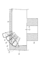

Classifications
-
- B—PERFORMING OPERATIONS; TRANSPORTING
- B62—LAND VEHICLES FOR TRAVELLING OTHERWISE THAN ON RAILS
- B62D—MOTOR VEHICLES; TRAILERS
- B62D15/00—Steering not otherwise provided for
- B62D15/02—Steering position indicators ; Steering position determination; Steering aids
- B62D15/027—Parking aids, e.g. instruction means
- B62D15/0285—Parking performed automatically
-
- B—PERFORMING OPERATIONS; TRANSPORTING
- B60—VEHICLES IN GENERAL
- B60W—CONJOINT CONTROL OF VEHICLE SUB-UNITS OF DIFFERENT TYPE OR DIFFERENT FUNCTION; CONTROL SYSTEMS SPECIALLY ADAPTED FOR HYBRID VEHICLES; ROAD VEHICLE DRIVE CONTROL SYSTEMS FOR PURPOSES NOT RELATED TO THE CONTROL OF A PARTICULAR SUB-UNIT
- B60W30/00—Purposes of road vehicle drive control systems not related to the control of a particular sub-unit, e.g. of systems using conjoint control of vehicle sub-units
- B60W30/06—Automatic manoeuvring for parking
-
- B—PERFORMING OPERATIONS; TRANSPORTING
- B60—VEHICLES IN GENERAL
- B60R—VEHICLES, VEHICLE FITTINGS, OR VEHICLE PARTS, NOT OTHERWISE PROVIDED FOR
- B60R21/00—Arrangements or fittings on vehicles for protecting or preventing injuries to occupants or pedestrians in case of accidents or other traffic risks
-
- B—PERFORMING OPERATIONS; TRANSPORTING
- B60—VEHICLES IN GENERAL
- B60W—CONJOINT CONTROL OF VEHICLE SUB-UNITS OF DIFFERENT TYPE OR DIFFERENT FUNCTION; CONTROL SYSTEMS SPECIALLY ADAPTED FOR HYBRID VEHICLES; ROAD VEHICLE DRIVE CONTROL SYSTEMS FOR PURPOSES NOT RELATED TO THE CONTROL OF A PARTICULAR SUB-UNIT
- B60W30/00—Purposes of road vehicle drive control systems not related to the control of a particular sub-unit, e.g. of systems using conjoint control of vehicle sub-units
- B60W30/08—Active safety systems predicting or avoiding probable or impending collision or attempting to minimise its consequences
- B60W30/09—Taking automatic action to avoid collision, e.g. braking and steering
-
- B—PERFORMING OPERATIONS; TRANSPORTING
- B62—LAND VEHICLES FOR TRAVELLING OTHERWISE THAN ON RAILS
- B62D—MOTOR VEHICLES; TRAILERS
- B62D15/00—Steering not otherwise provided for
- B62D15/02—Steering position indicators ; Steering position determination; Steering aids
- B62D15/021—Determination of steering angle
- B62D15/024—Other means for determination of steering angle without directly measuring it, e.g. deriving from wheel speeds on different sides of the car
-
- B—PERFORMING OPERATIONS; TRANSPORTING
- B62—LAND VEHICLES FOR TRAVELLING OTHERWISE THAN ON RAILS
- B62D—MOTOR VEHICLES; TRAILERS
- B62D15/00—Steering not otherwise provided for
- B62D15/02—Steering position indicators ; Steering position determination; Steering aids
- B62D15/027—Parking aids, e.g. instruction means
-
- B—PERFORMING OPERATIONS; TRANSPORTING
- B62—LAND VEHICLES FOR TRAVELLING OTHERWISE THAN ON RAILS
- B62D—MOTOR VEHICLES; TRAILERS
- B62D15/00—Steering not otherwise provided for
- B62D15/02—Steering position indicators ; Steering position determination; Steering aids
- B62D15/027—Parking aids, e.g. instruction means
- B62D15/028—Guided parking by providing commands to the driver, e.g. acoustically or optically
-
- G—PHYSICS
- G08—SIGNALLING
- G08G—TRAFFIC CONTROL SYSTEMS
- G08G1/00—Traffic control systems for road vehicles
- G08G1/16—Anti-collision systems
- G08G1/168—Driving aids for parking, e.g. acoustic or visual feedback on parking space
-
- B—PERFORMING OPERATIONS; TRANSPORTING
- B60—VEHICLES IN GENERAL
- B60Y—INDEXING SCHEME RELATING TO ASPECTS CROSS-CUTTING VEHICLE TECHNOLOGY
- B60Y2300/00—Purposes or special features of road vehicle drive control systems
- B60Y2300/06—Automatic manoeuvring for parking
-
- B—PERFORMING OPERATIONS; TRANSPORTING
- B60—VEHICLES IN GENERAL
- B60Y—INDEXING SCHEME RELATING TO ASPECTS CROSS-CUTTING VEHICLE TECHNOLOGY
- B60Y2300/00—Purposes or special features of road vehicle drive control systems
- B60Y2300/08—Predicting or avoiding probable or impending collision
- B60Y2300/09—Taking automatic action to avoid collision, e.g. braking or steering
Definitions
- the present invention relates to a parking support device and a parking support method that support a parking operation in which a vehicle is parked in parallel in a parking area.
- a parking support device that supports a parking operation in which the vehicle is parked while moving the vehicle backward from the reverse start position toward the target parking position is known (see Patent Document 1).
- parking assistance is performed so that the avoidance point set around the target parking position is avoided.
- the parking assist device described in Patent Document 1 focuses only on collision avoidance on a path that moves backward from the reverse start position to the target parking position. For this reason, when the width of the roadway facing the parking area is narrow, interference with an obstacle already occurs at the reverse start position, so that a scene where parking assistance is possible is limited.
- the present invention has been made in view of the above problems, and its object is to provide a parking assist device capable of generating a route that does not interfere with obstacles around the roadway, even in an environment where the width of the roadway is narrow. To provide a parking assistance method.
- the parking assist device generates a route through which a vehicle moves to a parking area via a turn-back position.
- the parking assist device searches for the attitude angle of the vehicle at the turn-back position based on the width of the roadway so that a route can be generated in which the front portion of the vehicle does not interfere with an obstacle adjacent in the width direction of the roadway at the turn-back position. .
- a route that does not interfere with obstacles in the vicinity of a roadway can be obtained even in an environment where the width of the roadway is narrow by searching for a posture angle of the vehicle at the turning position based on the width of the roadway. Can be generated.
- FIG. 1 is a block diagram illustrating a configuration of the parking support apparatus according to the first embodiment.
- FIG. 2 is a top view showing an example of mounting the in-vehicle cameras 1a to 1d on the vehicle.
- FIG. 3A is a block diagram showing a plurality of information processing circuits configured by the parking assistance controller 10a according to the first embodiment
- FIG. 3B is a parking assistance controller 10b according to the second embodiment. It is a block diagram which shows the some information processing circuit comprised by these.
- FIG. 4 is a top view showing definitions of main terms in the first embodiment.
- FIG. 5 is a flowchart illustrating an example of a method for generating a “single turn back parking route” performed by the parking support apparatus of FIG. 1.
- FIG. 5 is a flowchart illustrating an example of a method for generating a “single turn back parking route” performed by the parking support apparatus of FIG. 1.
- FIG. 5 is a flowchart illustrating an example of a method
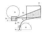
- FIG. 6 is a diagram for explaining the step (S03) of determining the interference between the right front portion of the vehicle and the obstacle (Ob 1 ) at the turning-back position (Pb).
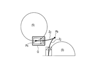
- FIG. 7 is a diagram for explaining the step (S13) of determining the interference between the vehicle and the obstacle (Ob 2 ) between the turn-back position (Pb) and the target parking position (Pc).
- FIG. 8 is a flowchart showing an example of a detailed procedure of step S01 in FIG.
- FIG. 9 is a diagram showing a vehicle model by Ackermann-Jeantaud.
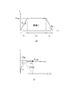
- FIG. 10 is a graph showing the relationship between the curvature ( ⁇ ) of the clothoid curve and the travel locus, and shows a case where the tire is steered to the maximum curvature ( ⁇ max ) corresponding to the minimum turning radius of the vehicle.
- FIG. 11 is a graph showing the relationship between the curvature ( ⁇ ) of the clothoid curve and the travel locus, and shows a case where the tire is not steered up to the maximum curvature ( ⁇ max ).
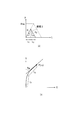
- FIG. 12 is a graph showing a range that can be taken by the end point of the locus by the clothoid curve.
- FIG. 13 is a diagram illustrating a basic clothoid curve (Za) starting from the parking start position (Pa) and a basic clothoid curve (Zb) starting from the target parking position (Pc).
- Figure 14 is a clothoid curve of the parking start position from (Pa) to the turning-back position (Pb) (Z 1), a diagram showing clothoid curve (Z 2) from the turning-back position (Pb) to the target parking position (Pc) is there.
- FIG. 15 is a top view showing definitions of main terms in the second embodiment.
- FIG. 16 is a flowchart showing an example of a method of generating a “single turn back parking route” using the parking assist controller 10b of FIG. FIG.
- FIG. 17 is a diagram illustrating a procedure for searching in a direction in which the posture angle ( ⁇ M ) is subtracted from the initial value.
- FIG. 18 is a diagram for explaining a procedure for shifting the target parking position (Pc ′) in the vehicle approach direction from FIG. 17 and searching again for the attitude angle ( ⁇ M ).
- the parking assist device is mounted on a vehicle, calculates a route for moving the vehicle from a parking start position (for example, a current position) to a parking available area, and guides the vehicle along the route. Specifically, the parking assistance device guides the vehicle by automatically controlling the steering of the vehicle. As shown in FIG.
- the parking assistance device includes a parking assistance controller 10, four vehicle-mounted cameras 1a to 1d that capture images around the vehicle, a laser range finder (LRF) 8a that detects obstacles around the vehicle, 8b, a display 2, a speaker 3 for outputting a guide sound, a steering actuator 4 for driving a vehicle steering, an operation input device 5 for receiving an operation input by a driver of the vehicle, and a steering angle for detecting a steering angle of the vehicle A sensor 6 and a vehicle speed sensor 7 for detecting the vehicle speed of the vehicle are provided.
- LRF laser range finder
- the in-vehicle cameras 1a to 1d are, for example, CCD cameras or CMOS cameras having an angle of view of about 180 degrees. It is mounted at a suitable location on the vehicle so that the four in-vehicle cameras 1a to 1d can take images of all areas surrounding the vehicle. Specifically, as shown in FIG. 2, for example, the in-vehicle camera 1a is attached to the front grille of the own vehicle, the in-vehicle camera 1b is attached to the left door mirror, the in-vehicle camera 1c is attached to the rear finisher, and the in-vehicle camera 1d is attached to the right door mirror. A video of a predetermined area around is taken.
- the in-vehicle cameras 1a to 1d While the vehicle is moving, the in-vehicle cameras 1a to 1d continuously take images, and the distance and direction to an obstacle (including other vehicles and walls) appearing in a plurality of images can be measured. .
- a pair of cameras may simultaneously capture images and measure the distance and direction from the two images to the obstacle.
- the in-vehicle cameras 1a to 1d can identify a parking frame as an example of a parking area by recognizing white lines drawn on the road surface in addition to obstacles. A white line can be recognized by performing edge detection processing on the video.
- Laser range finders (LRF) 8a and 8b can irradiate an obstacle with an infrared laser and measure the distance and direction to the obstacle based on the degree of reflection.
- the laser range finders 8a and 8b have a viewing angle of 200 degrees or more. Therefore, the distance from the left side surface or the right side surface to the obstacle existing in the vehicle front direction is detected.
- the clearance sonar using an ultrasonic wave is mention
- the display 2 is a display device such as a liquid crystal display installed in the vehicle interior of the vehicle, and is useful for a bird's-eye view image generated around the vehicle generated by the parking assist controller 10 and for a driver performing a driving operation during parking. Displays various support information.
- the speaker 3 an audio speaker generally mounted on a vehicle is used, and various guide sounds for parking assistance are output.
- the display 2 can display a graphic indicating the current position of the vehicle, a frame graphic indicating the target parking position and the turning position, and information indicating the steering angle at the current position or turning position of the vehicle.
- the speaker 3 can perform voice guidance for guiding the steering direction of the steering wheel so that the vehicle moves along the route. Thereby, finer parking assistance becomes possible.
- the steering actuator 4 is controlled by the parking assist controller 10 and drives the steering of the vehicle.
- the steering actuator 4 for example, a steering drive motor of an electric power steering device (EPS) that electrically assists a steering operation by a driver is used.
- EPS electric power steering device
- the parking assist controller 10 automatically controls the steering of the vehicle so that the vehicle moves along the route. This automatic steering control can further reduce the driver's operation burden during the parking operation.
- the operation input device 5 accepts various operation inputs by the driver of the vehicle, and includes, for example, direction keys and a touch panel.
- the operation input device 5 inputs an operation signal corresponding to the operation input to the parking support controller 10.
- the target parking position input by the driver and the attitude angle of the vehicle at the target parking position are received.
- the steering angle sensor 6 and the vehicle speed sensor 7 input information on the steering angle and the vehicle speed of the vehicle to the parking assistance controller 10 as needed.
- the parking support controller 10 includes, for example, a microcontroller including a CPU, a memory, and an input / output unit, and configures a plurality of information processing circuits included in the parking support apparatus by executing a computer program installed in advance.
- the parking assistance controller 10 executes a series of information processing cycles for calculating a route to the parking frame.
- the parking assistance controller 10 may also be used as an electronic control unit (ECU) used for other control related to the vehicle.
- ECU electronice control unit
- the plurality of information processing circuits configured by the parking assist controller 10 include a route generation circuit 21, a road width acquisition circuit 22, a parking width acquisition circuit 23, and an attitude angle search circuit 24.
- the target parking position search circuit 25 is included.
- the route generation circuit 21 generates a route that moves from the parking start position (Pa) to the parking frame (G) where the vehicle is parked via the return position (Pb). Specifically, the vehicle moves forward from the parking start position (Pa) to the turn-back position (Pb), and then turns back and moves backward to the target parking position (Pc) set in the parking frame (G). A so-called “single turn parking route” is generated.
- the route generation circuit 21 sets the target parking position and the posture angle at the target parking position with reference to the vehicle at the start of parking.
- the route generation circuit 21 sets, for example, a target parking position (Pc) with respect to the parking start position (Pa), with the vehicle position when starting parking assistance as the parking start position (Pa). That is, the target parking position (Pc) in the coordinate system with the parking start position (Pa) as the origin is set. Further, for example, an angle formed by the traveling direction (Dc) of the vehicle at the target parking position (Pc) with respect to the traveling direction (Da) of the vehicle at the parking start position (Pa), that is, a posture angle ( ⁇ F ) is set.
- the “posture angle ( ⁇ )” is an angle with respect to the traveling direction of the vehicle at the start of parking.
- the posture angle is not limited to the angle with respect to the traveling direction of the vehicle at the start of parking.
- the attitude angle may be an angle with respect to an obstacle (Ob 1 ) adjacent in the width direction of the roadway or an angle with respect to an obstacle (Ob 2 ) adjacent in the width direction of the parking area.
- a parking start position a target parking position, and a turning-back position (described later), for example, an intermediate position between two rear wheels is exemplified.
- the path generation circuit 21 receives signals output from various sensors including the in-vehicle cameras 1a to 1d, laser range finders (LRF) 8a and 8b, and clearance sonar. Then, it recognizes the position and direction of obstacles (including other cars and walls) and white lines around the vehicle, detects a parking area, and targets and parks the target parking position when parking the vehicle in the parking area. Specify the posture angle at the position. The recognized obstacle and white line information is recorded in the ECU as map information.
- information from an infrastructure facility that provides information on an available parking space may be acquired, and a target parking position and an attitude angle at the position may be specified. Or you may display the image image
- the route generation circuit 21 performs one turn using the “one turn turn base algorithm” based on the target parking position, the posture angle at the position, and the posture angle ( ⁇ M ) at the turn back position (Pb). Generate a parking route.
- the “single turn-back base algorithm” will be described later with reference to FIGS.
- the route generation circuit 21 can simultaneously specify the return position (Pb) shown in FIG. 4 by generating the route.
- the road width acquisition circuit 22 recognizes the “roadway” shown in FIG. 4 based on the positions and directions of obstacles (including other vehicles and walls) and white lines recognized by the route generation circuit 21.
- the width (W R ) is calculated.
- “Driving road” refers to an area facing a parking area (for example, parking frame G) where the vehicle can travel.
- the road width acquisition circuit 22 calculates the width (W R ) of an area (vehicle path) where the vehicle can travel based on the position and direction of obstacles (including other vehicles and walls) around the vehicle and the white line. Is possible. Of course, you may acquire the information regarding the width
- the parking width acquisition circuit 23 calculates the width of the parking available area detected by the route generation circuit 21.
- the road width (W R ) may be acquired from the outside or set to a value input by the driver.
- the parking frame width (W A ) shown in FIG. 4 is used as an example of the width of the parking area.
- the attitude angle search circuit 24 searches for the attitude angle ( ⁇ M ) of the vehicle at the turning-back position (Pb) based on the road width (W R ). At this time, the posture angle search circuit 24 can generate a posture angle ( ⁇ M ) so that the front portion of the vehicle does not interfere with the obstacle (Ob 1 ) adjacent in the width direction of the roadway at the turning position (Pb). ).
- the attitude angle search circuit 24 sets the attitude angle ( ⁇ M ) of the vehicle at the turning-back position (Pb). Then, it is determined whether or not the front portion of the vehicle interferes with the obstacle (Ob 1 ) at the turning position (Pb) of the route generated based on the set posture angle ( ⁇ M ). And when it is judged that it interferes, the attitude angle ((theta) M ) of the vehicle in a turning-back position (Pb) is changed. It is determined whether or not the front portion of the vehicle interferes with an obstacle adjacent in the width direction of the roadway at the route turning position (Pb) generated based on the changed attitude angle. Until it is determined that there is no interference, the posture angle ( ⁇ M ) is changed and the path is generated repeatedly. As described above, the attitude angle search circuit 24 searches for the attitude angle ( ⁇ M ) of the vehicle so that a path that does not interfere with the obstacle can be generated.
- the posture angle search circuit 24 starts searching for the posture angle ( ⁇ M ) from the posture angle ( ⁇ F ) at the end of parking. Then, when searching in a direction decreasing from the attitude angle ( ⁇ F ), that is, when it is determined that interference occurs, the attitude angle ( ⁇ M ) of the vehicle at the turn-back position (Pb) is reduced to obtain a new attitude angle ( ⁇ M ). And Then, the attitude angle search circuit 24 selects the largest attitude angle ( ⁇ M ) among the attitude angles ( ⁇ M ) of the vehicle that can generate a route that does not interfere with the obstacle (Ob 1 ) at the turning position (Pb). . By selecting the largest posture angle, it is possible to generate a route in which the vehicle is unlikely to interfere with the obstacle (Ob 2 ) between the turn-back position (Pb) and the target parking position (Pc).
- the target parking position search circuit 25 generates a road width (W R ) so that a route in which the front portion of the vehicle does not interfere with an obstacle (Ob 1 ) adjacent in the width direction of the road at the turn-back position (Pb). Based on this, the target parking position (Pc) in the parking frame (G) is searched.
- the target parking position search circuit 25 sets a target parking position (Pc) in the parking frame (G). Then, it is determined whether or not the front portion of the vehicle interferes with the obstacle (Ob 1 ) at the turn-back position (Pb) of the route generated based on the set target parking position (Pc). And when it is judged that it interferes, the target parking position (Pc) in a parking frame (G) is changed. It is determined whether or not the front portion of the vehicle interferes with an obstacle adjacent in the width direction of the roadway at the route turning position (Pb) generated based on the changed target parking position (Pc). The target parking position (Pc) is changed and the route is generated repeatedly until it is determined that there is no interference. As described above, the target parking position search circuit 25 searches for the target parking position (Pc) so that a route that does not interfere with the obstacle can be generated.
- the target parking position search circuit 25 starts searching for the target parking position (Pc) from the end portion (G F ) of the parking frame (G) on the vehicle entry side. That is, the depth (B) is set to zero and the generation of the route is started. And when it searches for the direction which increases depth (B), ie, it judges that it interferes, a target parking position (Pc) is moved to the approach direction of a vehicle, and it is set as a new target parking position (Pc).
- the target parking position search circuit 25 selects a target parking position (Pc) having the smallest depth (B) from among the target parking positions (Pc) that can generate a route that does not interfere with the obstacle (Ob 1 ) at the turn-back position (Pb). As a result, a route in which the vehicle is unlikely to interfere with the obstacle (Ob 2 ) can be generated between the turn-back position (Pb) and the target parking position (Pc).
- the parking assist device measures an area where the vehicle can travel including the parking area (parking frame G) and the road width (W R ). And in order to obtain
- step S01 a route for moving from the parking start position (Pa) to the parking frame (G) where the vehicle is parked is generated via the return position (Pb) using the “one turn return base algorithm”.
- the posture angle ( ⁇ M ) at the turn-back position (Pb) is set to the posture angle ( ⁇ F ) at the end of parking, and the end of the parking frame (G) on the road side (G F )
- a target parking position (Pc) is set. Details of step S01 will be described later with reference to FIGS.
- the parking assist controller 10a determines whether or not the front portion of the vehicle interferes with an obstacle (Ob 1 ) adjacent to the roadway at the generated turnback position (Pb) of the route. Specifically, as shown in FIG. 6, whether or not the right front portion of the vehicle interferes with an obstacle (Ob 1 ) beyond the roadway (travelable area) at the turn-back position (Pb) (K 1 ) Determine. If there is no interference (NO in S03), the process proceeds to step S13. If there is interference (YES in S03), the process proceeds to step S05.
- step S05 it is determined whether or not the posture angle ( ⁇ M ) can be reduced. If the current posture angle ( ⁇ M ) is already a minimum value (eg, zero), it cannot be reduced. If the posture angle ( ⁇ M ) can be reduced (YES in S05), the posture angle ( ⁇ M ) is reduced, and the process returns to step S01 to generate a path again with the reduced posture angle ( ⁇ M ).
- a minimum value eg, zero
- the posture angle ( ⁇ M ) cannot be reduced (YES in S05)
- the target parking position (Pc) that causes the vehicle to deviate from the parking frame (G) cannot be set. If the depth (B) can be increased (YES in S09), the depth (B) is increased.
- the posture angle ( ⁇ M ) is reset to the initial value, that is, the parking posture angle ( ⁇ F ). Then, the process returns to step S01, and a route is generated again at the new target parking position (Pc). In this way, first, a path without interference is searched while scanning in the direction in which the attitude angle ( ⁇ M ) is subtracted from the initial value. When the posture angle ( ⁇ M ) reaches the limit, the target parking position (Pc) is changed, and the posture angle ( ⁇ M ) is scanned from the initial value again.
- step S13 the parking support controller 10a determines whether the vehicle interferes with the obstacle (Ob 2 ) between the turn-back position (Pb) and the target parking position (Pc) (K 2 ).
- the target parking position (Pc) is moved in the parking frame width direction within a range not exceeding the parking frame (G) (NO in S17).
- the posture angle ( ⁇ M ) is reset to the posture angle ( ⁇ F ) at the end of parking.
- the depth (B) of the target parking position (Pc) is also reset to zero.
- step S21 If the target parking position (Pc) cannot be moved in the parking frame width direction within a range not exceeding the parking frame (G) (YES in S17), the process proceeds to step S21.
- step S15 the route generated in the cycle is adopted as a route suitable for the travelable area.
- step S101 the route generation circuit 21 detects a parking area (including the parking frame G) from the position and direction of obstacles (including other cars and walls) and white lines around the vehicle, and the parking area A target parking position (Pc) and a posture angle ( ⁇ F ) at the target parking position (Pc) when the vehicle is parked are specified.
- a parking area including the parking frame G
- obstacles including other cars and walls
- ⁇ F posture angle
- the path generation circuit 21 sets an attitude angle ( ⁇ M ) at the turning-back position (Pb).
- the posture angle ( ⁇ F ) is set as the posture angle ( ⁇ M )
- the posture angle ( ⁇ M ) is changed according to the instruction in step S07, S11, or S19. Reset.
- step S105 the route generation circuit 21 calculates a basic clothoid curve based on the target parking position (Pc), the posture angle ( ⁇ F ), and the posture angle ( ⁇ M ).
- a basic clothoid curve calculation method will be described with reference to FIGS.
- FIG. 9 shows the vehicle model.
- Lw [m] is the wheel base
- ⁇ (t) [rad] is the front wheel turning angle
- V (t) [m / s] is the vehicle speed at the rear axle center (P)
- ⁇ (t) [rad ] Is the attitude angle of the vehicle
- ⁇ (t) is the curvature of the trajectory along which the rear wheel axle center (P) has moved.
- Equation (1) The differential equation with respect to the time (t) of the rear wheel axle center (P) is expressed by equation (1).
- equation (3) The time derivative of unit distance is expressed by equation (2). Therefore, when equation (1) is rewritten as a differential equation with respect to travel distance (L), equation (3) is obtained.
- L represents a travel distance
- k represents a curvature change rate.
- the traveling trajectories (L1 and L3) form a clothoid curve because the steering angular speed of the steering wheel is constant.
- the traveling locus (L2) forms an arc because the steering angle of the steering wheel is constant, that is, the angular velocity is zero.
- the curvature ( ⁇ ) is expressed by equation (4). Therefore, when the curvature change rate (k) and the maximum curvature ( ⁇ max ) are determined and the target posture angle ( ⁇ ) is set, the change pattern of the curvature ( ⁇ ) is uniquely determined.
- the relationship between the curvature ( ⁇ ) and the front wheel steering angle ( ⁇ ) has a one-to-one correspondence. For this reason, when the target posture angle ( ⁇ ) is set, the front wheel steering angle ( ⁇ ) is also uniquely determined.
- this travel locus is called a basic clothoid curve (Za).
- the basic clothoid curve (Za) it is possible to enlarge the similarity and add a straight line before and after the start point (Pa) or the end point (Pb).
- position angle ((theta) M ) can be drawn.
- a clothoid curve that becomes the posture angle ( ⁇ M ) cannot be drawn.
- the turn-back position (Pb) can be set in the areas (2) and (3), but the turn-back position (Pb) cannot be set in the areas (1), (4), and (5).
- the region (2) is a region that can be reached by first going straight from the parking start position (Pa) and then drawing a clothoid curve.
- the area (3) is an area that can be reached by first drawing a clothoid curve from the parking start position (Pa) and then going straight ahead.
- FIG. 13 shows a basic clothoid curve (Za) starting from the parking start position (Pa), and the region (S1) corresponds to the region (2) and the region (3) shown in FIG. Similarly, a basic clothoid curve (Zb) that forms an angle ( ⁇ F ⁇ M ) obtained by subtracting the posture angle ( ⁇ M ) from the posture angle ( ⁇ F ) can be calculated from the target parking position (Pc). It is.
- the region (S2) indicates a region in which a clothoid curve having an angle ( ⁇ F ⁇ M ) from the target parking position (Pc) can be drawn.
- step S105 a basic clothoid curve (Za) starting from the parking start position (Pa) and a basic clothoid curve (Zb) starting from the target parking position (Pc) are calculated. Proceeding to step S107, the areas (S1, S2) shown in FIG. 13 are calculated.
- step S109 an area (S12) where the area (S1) and the area (S2) overlap is extracted.
- the lengths of the clothoid curve starting from the parking start position (Pa) and the clothoid curve starting from the target parking position (Pc) in the region (S12) are the shortest.
- the position is selected as the turn-back position (Pb).
- step S111 as shown in FIG. 14, a clothoid curve (Z 1 ) from the parking start position (Pa) to the turn-back position (Pb) and a clothoid curve (Pc) from the turn-back position (Pb) to the target parking position (Pc) ( Z 2 ). This completes the path.
- the attitude angle search circuit 24 sets the road width (W R ) so that a path in which the front portion of the vehicle does not interfere with an obstacle (Ob 1 ) adjacent in the width direction of the road at the turning position (Pb) can be generated. Based on this, the attitude angle ( ⁇ M ) of the vehicle at the turning-back position (Pb) is searched. Thereby, even in an environment where the road width (W R ) is narrow, it is possible to generate a path that does not interfere with obstacles (Ob 1 , Ob 2 ) around the road.
- the posture angle search circuit 24 has the largest posture angle among the vehicle posture angles ( ⁇ M ) that can generate a route in which the front portion of the vehicle does not interfere with an obstacle adjacent in the width direction of the roadway at the turning position (Pb). Select. It is possible to generate a route in which the vehicle does not easily interfere with the obstacle after the turn-back position.
- the initial value of the orientation angle (theta M) a (starting attitude angle) has been described a case where the parking end position angle (theta M).
- the narrower the road width (W R ) the smaller the posture angle ( ⁇ M ) at the turning position (Pb) tends to be. Therefore, when searching for the posture angle ( ⁇ M ) in a direction that decreases from the initial value (starting posture angle), the initial value (starting posture angle) may be reduced as the road width (W R ) is narrower. Good. Thereby, useless search time can be reduced, information processing load can be reduced, and rapid route calculation can be performed.
- the posture angle search circuit 24 moves the target parking position (Pc) from the end (G F ) of the parking frame (G) on the side where the vehicle enters (S11). Then, the attitude angle search circuit 24 searches for the attitude angle ( ⁇ M ) of the vehicle at the turn-back position (Pb) based on the target parking position (Pc) after movement.
- the target parking position (Pc) By moving the target parking position (Pc) in the vehicle approach direction, the same effect as that of widening the vehicle width (W R ) can be obtained in route formation. Therefore, even in an environment where the road width (W R ) is narrow, it is possible to generate a path that does not interfere with obstacles around the road.
- the attitude angle search circuit 24 is configured to move the vehicle in the approach direction (Pc) among the target parking positions (Pc) that can generate a route in which the vehicle does not interfere with the obstacle (Ob 2 ) adjacent in the width direction of the parking frame ( The target parking position (Pc) with the smallest depth B) is selected. As a result, it is possible to generate a route in which the vehicle is unlikely to interfere with the obstacle (Ob 2 ) between the turn-back position (Pb) and the target parking position (Pc).
- the attitude angle search circuit 24 determines that it is not possible to generate a route for the vehicle to move to the parking frame (G) via the turn-back position (Pb) (S21). It can be determined that it is difficult to generate a “single turn back parking route” using the posture angle ( ⁇ M ) and the depth (B) of the parking target position (Pc) as variables. Therefore, it is possible to start generating a parking route that performs turnover twice or more. Alternatively, the vehicle may be actually moved to a position before it hits the obstacle, and then route generation may be attempted again.
- the attitude angle search circuit 24 sets the attitude angle ( ⁇ M ) of the vehicle at the turning-back position (Pb) (S103). It is determined whether or not the front portion of the vehicle interferes with an obstacle (Ob 1 ) adjacent to the roadway at the route turning position (Pb) generated based on the set posture angle ( ⁇ M ) ( S03). When it is determined that interference occurs (YES in S03), the posture angle ( ⁇ M ) of the vehicle at the turning position is changed (S07), and the turning position (Pb) of the route generated based on the changed posture angle ( ⁇ M ). ), It is determined whether or not the front portion of the vehicle interferes with an obstacle adjacent in the width direction of the roadway (S03). Thereby, formation of a path, determination of interference, and change of posture angle can be repeatedly performed. Therefore, a path without interference can be generated by searching for the posture angle ( ⁇ M ).
- the target parking position search circuit 25 generates a road width (W R ) so that a route in which the front portion of the vehicle does not interfere with an obstacle (Ob 1 ) adjacent in the width direction of the road at the turn-back position (Pb). Based on this, the target parking position (Pc) in the parking frame (G) is searched.
- the target parking position (Pc) can be moved by searching for the target parking position (Pc) based on the road width (W R ). Thereby, the same effect as widening the vehicle width (W R ) can be obtained in the route formation. Therefore, even in an environment where the width of the roadway is narrow, a route that does not interfere with obstacles around the roadway can be generated.
- the parking assist device searches for a posture angle ( ⁇ M ) and a target parking position (Pc) based not only on the road width (W R ) but also on the road depth (E). At this time, the posture angle ( ⁇ M ) and the target parking position (Pc) are searched so that a route that does not interfere with obstacles around the roadway can be generated.
- the plurality of information processing circuits configured by the parking assistance controller 10b according to the second embodiment include not only the circuits (21 to 25) shown in FIG.
- a road depth acquisition circuit 26 that acquires the road depth (E) is also included.
- the lane depth acquisition circuit 26 recognizes the lane depth (E shown in FIG. 15) based on the obstacles (including other vehicles and walls) and the position and direction of the white line recognized by the route generation circuit 21. ) Is calculated. “Road depth (E)” indicates the distance from the target parking position (Pc) to the end of the road in the direction perpendicular to the road width (W R ).
- the vehicle path depth acquisition circuit 26 acquires the position and direction of obstacles (including other vehicles and walls) and white lines around the vehicle from the path generation circuit 21.
- the vehicle path depth acquisition circuit 26 can calculate the depth (E) of the area (vehicle path) in which the vehicle can travel based on the position and direction of obstacles (including other vehicles and walls) around the vehicle and the white line. It is.
- the information about the vacant parking space and the information about the depth of the roadway may be acquired from the infrastructure equipment.
- the attitude angle search circuit 24 can generate a path so that the front part of the vehicle does not interfere with obstacles (Ob 1 , 0b 3 ) adjacent to the width direction and the depth direction of the road direction at the turning position (Pb).
- the vehicle attitude angle ( ⁇ M ) at the turn-back position (Pb) is searched based on the width of the vehicle and the depth of the roadway.
- the attitude angle search circuit 24 controls the scanning direction of the attitude angle ( ⁇ M ) according to the size of the road depth (E) and the road width (W R ).
- the posture angle ( ⁇ M ) tends to be large, and when the lane width (W R ) is narrow, the posture angle ( ⁇ M ) tends to be small.
- the posture angle search circuit 24 can select a larger posture angle ( ⁇ M ) as the lane depth (E) is narrower.
- the posture angle search circuit 24 searches for the posture angle ( ⁇ M ) at the turn-back position (Pb) in a direction increasing from zero.
- the posture angle search circuit 24 uses the posture angle ( ⁇ M ) at the turn-back position (Pb) as the posture angle ( ⁇ Search in the direction of decreasing from F ). Thereby, useless search time can be reduced, information processing load can be reduced, and rapid route calculation can be performed.
- the distance may be determined using a predetermined threshold value for each of the road depth (E) and the road width (W R ). For example, when both the road depth (E) and the road width (W R ) are equal to or smaller than the threshold, and when only the road depth (E) is equal to or smaller than the threshold, the posture angle ( ⁇ M ) is parked. Search in a direction decreasing from the attitude angle ( ⁇ F ) at the end. When only the road width (W R ) is equal to or less than the threshold value, the attitude angle ( ⁇ M ) is searched in a direction that decreases from the attitude angle ( ⁇ F ) at the end of parking.
- the target parking position search circuit 25 searches for the target parking position (Pc) in the parking frame (G) based on the road width (W R ) and the road depth (E).
- the target parking position (Pc) can be moved by searching for the target parking position (Pc) based on the road width (W R ) and the road depth (E). Thereby, the same effect as widening the vehicle width (W R ) can be obtained in the route formation. Therefore, even in an environment where the width of the roadway is narrow, a route that does not interfere with obstacles around the roadway can be generated.
- step S12 is further provided between step S03 and step S13 in FIG.
- step S12 the parking assist controller 10b determines whether or not the front portion of the vehicle interferes with an obstacle (Ob 3 ) adjacent to the roadway at the generated turn-back position (Pb) of the route. Specifically, as shown in FIG. 17, it is determined whether or not the left front portion of the vehicle interferes with an obstacle (Ob 3 ) beyond the roadway (travelable area) at the turning position (Pb). To do. If there is no interference (NO in S03), the process proceeds to step S13. If there is interference (YES in S03), the process proceeds to step S09. The other steps S01 to S21 are the same as those in FIG.
- FIGS. 17 and 18 an example of a search for a posture angle ( ⁇ M ) by the posture angle search circuit 24 and a search for a target parking position (Pc) by the target parking position search circuit 25 will be shown.
- the target parking position (Pc) is determined, and the path formation (S01) and the interference diagnosis (S03) are repeatedly executed while scanning in the direction in which the posture angle ( ⁇ M ) is subtracted from the initial value.
- Pb 1 , Pb 2 , Pb 3 , Pb 4 ,..., Pb 6 indicate the turn-back positions in a total of 6 path formations.
- the path formation (S01) and the interference diagnosis (S03) are repeatedly executed while scanning in the direction in which the posture angle ( ⁇ M ) is subtracted from the initial value.
- the turning position (Pb 1 ′, Pb 2 ′) it interferes with the obstacle (Ob 1 ), but at the turning position (Pb 3 ′), it does not interfere with the obstacle (Ob 1 , Ob 3 ) ( NO at S12).
- the parking assist controller 10b searches for the posture angle ( ⁇ M ) of the vehicle at the turn-back position (Pb) based on the road width (W R ) and the road depth (E). As a result, it is possible to generate a route in which the front portion of the vehicle does not interfere with obstacles (Ob 1 , Ob 3 ) adjacent in the width direction and the depth direction of the roadway at the turning position (Pb).
- the attitude angle search circuit 24 generates the path width (W R ) and the vehicle so that the front part of the vehicle does not interfere with the obstacles adjacent in the width direction and the depth direction of the road direction at the turning position (Pb). Based on the road depth (E), the vehicle attitude angle ( ⁇ M ) at the turn-back position (Pb) is searched. Even when not only the vehicle width (W R ) but also the vehicle depth (E) is narrow, a route in which the front portion of the vehicle does not interfere with the obstacles (Ob 1 , Ob 3 ) can be generated.
- the posture angle search circuit 24 selects a larger posture angle ( ⁇ M ) as the lane depth (E) is narrower. Even in a narrow environment (E), it is possible to generate a route that does not interfere with obstacles around the road.
- the posture angle search circuit 24 scans the posture angle ( ⁇ M ) at the turn-back position (Pb) in a direction increasing from zero.
- the posture angle search circuit 24 decreases the posture angle ( ⁇ M ) at the turn-back position (Pb) from the posture angle at the end of parking. To scan.
Landscapes
- Engineering & Computer Science (AREA)
- Mechanical Engineering (AREA)
- Transportation (AREA)
- Chemical & Material Sciences (AREA)
- Combustion & Propulsion (AREA)
- Automation & Control Theory (AREA)
- Physics & Mathematics (AREA)
- General Physics & Mathematics (AREA)
- Control Of Driving Devices And Active Controlling Of Vehicle (AREA)
- Steering Control In Accordance With Driving Conditions (AREA)
- Traffic Control Systems (AREA)
- Road Paving Structures (AREA)
Abstract
Description
次に、図面を参照して、本発明の実施の形態を詳細に説明する。
駐車などの車輪の横滑りが発生しない極低速走行時の解析では、Ackermann-Jeantaudによる車両モデルが有効であることが知られている。図9に、その車両モデルを示す。ここでLw[m]はホイールベース、δ(t)[rad]は前輪転舵角、V(t)[m/s]は後輪車軸中心(P)での車速、θ(t)[rad]は車両の姿勢角、ρ(t)は後輪車軸中心(P)が移動した軌跡の曲率である。後輪車軸中心(P)の時間(t)に対する微分方程式は、(1)式で表される。


車速一定かつハンドルの転舵角速度一定で走行した場合、車両の軌跡はクロソイド曲線となる。目標軌道の始点と終点でタイヤ転舵角が0[rad]となる操舵パターンは,据え切りを回避することができ、タイヤの摩耗やアクチュエータへの負荷を少なくする観点から有効である。この場合の曲率(ρ)と走行軌跡の関係を、図10及び図11に示す。図10は車両の最小回転半径に対応する最大曲率(ρmax)までタイヤを操舵させた場合を示し、図11は最大曲率(ρmax)までタイヤを操舵させない場合を示す。Lは走行距離、kは曲率変化率を示す。図10(a)及び図11(a)で、走行軌跡(L1及びL3)は、ハンドルの転舵角速度が一定であるため、クロソイド曲線を形成する。図10(a)で、走行軌跡(L2)は、ハンドルの転舵角が一定、即ち、角速度が零であるため、円弧を形成する。

駐車開始位置(Pa)と切返し位置(Pb)を結ぶ経路を、クロソイド曲線を用いて求めることを考える。切返し位置(Pb)における姿勢角(θM)が設定されたとき、駐車開始位置(Pa)における車両の進行方向に対して姿勢角(θM)を成すまでの走行軌跡はクロソイド曲線で一意に表すことができる。
第1実施形態では、駐車枠(G)に面する車路の幅(WR)に着眼した駐車支援の例(図4)を示した。本実施形態では、図15に示すように、車路の幅(WR)のみならず、車路の奥行き(車路奥行E)をも考慮して、障害物(Ob1、Ob2、Ob3)と干渉しない経路を生成する駐車支援装置及び方法を説明する。
22 車路幅取得回路
23 駐車幅取得回路
24 姿勢角探索回路
25 目標駐車位置探索回路
26 車路奥行き取得回路
E 車路奥行
G 駐車枠
Ob1、Ob2、Ob3 障害物
Pa 駐車開始位置
Pb 切返し位置
Pc 目標駐車位置
θM、θF 姿勢角
WR 車路幅
Claims (13)
- 車両を駐車可能エリアに並列駐車する駐車動作を支援する駐車支援装置であって、
前記車両が切返し位置を介して前記駐車可能エリアまで移動する経路を生成する経路生成回路と、
前記駐車可能エリアに面する車路の幅を取得する車路幅取得回路と、
前記切返し位置において前記車両の前部が前記車路の幅方向に隣接する障害物と干渉しない前記経路が生成できるように、前記車路の幅に基づいて前記切返し位置における前記車両の姿勢角を探索する姿勢角探索回路と、を備える
ことを特徴とする駐車支援装置。 - 前記姿勢角は、駐車開始時の前記車両の進行方向に対する角度、車路の幅方向に隣接する障害物に対する角度、又は、前記駐車可能エリアの幅方向に隣接する障害物に対する角度のいずれかであることを特徴とする請求項1に記載の駐車支援装置。
- 前記姿勢角探索回路は、前記切返し位置における前記姿勢角を、駐車終了時の前記姿勢角から減少する方向に探索し、
前記姿勢角探索回路は、前記切返し位置において前記車両の前部が車路の幅方向に隣接する障害物と干渉しない前記経路が生成できる前記車両の姿勢角のうち、最も大きい前記姿勢角を選択する
ことを特徴とする請求項1又は2に記載の駐車支援装置。 - 前記姿勢角探索回路は、前記切返し位置における前記姿勢角を、開始姿勢角から減少する方向に探索し、
前記姿勢角探索回路は、車路の幅が狭いほど、前記開始姿勢角を小さくする
ことを特徴とする請求項1又は2に記載の駐車支援装置。 - 前記車路の奥行きを取得する車路奥行き取得回路を更に備え、
前記姿勢角探索回路は、前記切返し位置において前記車両の前部が車路の幅方向及び奥行き方向に隣接する障害物と干渉しない前記経路が生成できるように、前記車路の幅及び前記車路の奥行きに基づいて前記切返し位置における前記車両の姿勢角を探索する
ことを特徴とする請求項1又は2に記載の駐車支援装置。 - 前記姿勢角探索回路は、車路の奥行きが狭いほど、大きな前記姿勢角を選択することを特徴とする請求項5に記載の駐車支援装置。
- 前記車路の奥行きが前記車路の幅よりも長い場合、前記姿勢角探索回路は、前記切返し位置における前記姿勢角を、零から増加する方向に探索し、
前記車路の奥行きが前記車路の幅以下である場合、前記姿勢角探索回路は、前記切返し位置における前記姿勢角を、駐車終了時の前記姿勢角から減少する方向に探索する
ことを特徴とする請求項5又は6に記載の駐車支援装置。 - 前記切返し位置における前記車両の姿勢角を探索しても、前記切返し位置において前記車両の前部が車路の幅方向に隣接する障害物と干渉しない前記経路が生成できない場合において、
前記姿勢角探索回路は、目標駐車位置を、前記車両が進入する側の前記駐車可能エリアの端部から前記車両の進入方向へ移動させ、
前記姿勢角探索回路は、移動後の目標駐車位置に基づいて、前記切返し位置における前記車両の姿勢角を探索する
ことを特徴とする請求項1~7のいずれか一項に記載の駐車支援装置。 - 前記駐車可能エリアの幅を取得する駐車幅取得回路を更に備え、
前記姿勢角探索回路は、前記車両が前記駐車可能エリアの幅方向に隣接する障害物と干渉しない前記経路を生成できる前記目標駐車位置のうち、前記車両の進入方向への移動量が最も小さい前記目標駐車位置を選択する
ことを特徴とする請求項8に記載の駐車支援装置。 - 駐車目標位置を、前記車両が進入する側の前記駐車可能エリアの端部から前記車両の進入方向へ移動させて、前記切返し位置における前記車両の姿勢角を探索しても、前記切返し位置において前記車両の前部が車路の幅方向に隣接する障害物と干渉しない前記経路が生成できない場合、前記姿勢角探索回路は、前記車両が前記切返し位置を介して前記駐車可能エリアまで移動する経路を生成することができないと判断する
ことを特徴とする請求項8又は9に記載の駐車支援装置。 - 前記姿勢角探索回路は、
前記切返し位置における前記車両の姿勢角を設定し、
設定された姿勢角に基づいて生成された前記経路の前記切返し位置において、前記車両の前部が前記車路に隣接する障害物と干渉するか否かを判断し、
干渉すると判断した場合、前記切返し位置における前記車両の姿勢角を変更し、
変更された姿勢角に基づいて生成された前記経路の前記切返し位置において、前記車両の前部が前記車路の幅方向に隣接する障害物と干渉するか否かを判断する
ことを特徴とする請求項1又は2に記載の駐車支援装置。 - 前記切返し位置において前記車両の前部が前記車路の幅方向に隣接する障害物と干渉しない前記経路が生成できるように、前記車路の幅に基づいて前記駐車可能エリアにおける目標駐車位置を探索する目標駐車位置探索回路をさらに備えることを特徴とする請求項1又は2に記載の駐車支援装置。
- 車両を駐車可能エリアに並列駐車する駐車動作を支援する駐車支援方法であって、
前記車両が切返し位置を介して前記駐車可能エリアまで移動する経路を生成し、
前記駐車可能エリアに面する車路の幅を取得し、
前記切返し位置において前記車両の前部が前記車路の幅方向に隣接する障害物と干渉しない前記経路が生成できるように、前記車路の幅に基づいて前記切返し位置における前記車両の姿勢角を探索する
ことを特徴とする駐車支援方法。
Priority Applications (10)
| Application Number | Priority Date | Filing Date | Title |
|---|---|---|---|
| BR112017027321-7A BR112017027321B1 (pt) | 2015-06-19 | 2015-06-19 | Dispositivo e método de assistência ao estacionamento |
| JP2017524262A JP6551525B2 (ja) | 2015-06-19 | 2015-06-19 | 駐車支援装置及び駐車支援方法 |
| EP15895663.1A EP3312057B1 (en) | 2015-06-19 | 2015-06-19 | Parking assistance device and parking assistance method |
| CA2989980A CA2989980C (en) | 2015-06-19 | 2015-06-19 | Parking assistance device and parking assistance method |
| US15/736,546 US10414438B2 (en) | 2015-06-19 | 2015-06-19 | Parking assistance device and parking assistance method |
| CN201580081035.5A CN107735290B (zh) | 2015-06-19 | 2015-06-19 | 停车辅助装置及停车辅助方法 |
| MX2017016301A MX370048B (es) | 2015-06-19 | 2015-06-19 | Dispositivo de asistencia de estacionamiento y metodo de asistencia de estacionamiento. |
| PCT/JP2015/067742 WO2016203643A1 (ja) | 2015-06-19 | 2015-06-19 | 駐車支援装置及び駐車支援方法 |
| KR1020187000797A KR101990257B1 (ko) | 2015-06-19 | 2015-06-19 | 주차 지원 장치 및 주차 지원 방법 |
| RU2018101868A RU2668786C1 (ru) | 2015-06-19 | 2015-06-19 | Устройство помощи при парковке и способ помощи при парковке |
Applications Claiming Priority (1)
| Application Number | Priority Date | Filing Date | Title |
|---|---|---|---|
| PCT/JP2015/067742 WO2016203643A1 (ja) | 2015-06-19 | 2015-06-19 | 駐車支援装置及び駐車支援方法 |
Publications (1)
| Publication Number | Publication Date |
|---|---|
| WO2016203643A1 true WO2016203643A1 (ja) | 2016-12-22 |
Family
ID=57545512
Family Applications (1)
| Application Number | Title | Priority Date | Filing Date |
|---|---|---|---|
| PCT/JP2015/067742 Ceased WO2016203643A1 (ja) | 2015-06-19 | 2015-06-19 | 駐車支援装置及び駐車支援方法 |
Country Status (10)
| Country | Link |
|---|---|
| US (1) | US10414438B2 (ja) |
| EP (1) | EP3312057B1 (ja) |
| JP (1) | JP6551525B2 (ja) |
| KR (1) | KR101990257B1 (ja) |
| CN (1) | CN107735290B (ja) |
| BR (1) | BR112017027321B1 (ja) |
| CA (1) | CA2989980C (ja) |
| MX (1) | MX370048B (ja) |
| RU (1) | RU2668786C1 (ja) |
| WO (1) | WO2016203643A1 (ja) |
Cited By (12)
| Publication number | Priority date | Publication date | Assignee | Title |
|---|---|---|---|---|
| JP2018034541A (ja) * | 2016-08-29 | 2018-03-08 | 日産自動車株式会社 | 駐車支援方法及び駐車支援装置 |
| DE102018106804A1 (de) | 2017-03-29 | 2018-10-04 | Panasonic Intellectual Property Management Co., Ltd. | Routenerzeugungsvorrichtung, Routenerzeugungsverfahren und Routenerzeugungsprogramm |
| JP2018158604A (ja) * | 2017-03-22 | 2018-10-11 | アイシン精機株式会社 | 運転制御装置 |
| JP2018169950A (ja) * | 2017-03-30 | 2018-11-01 | 株式会社デンソーテン | 後方車両検出装置及び後方車両検出方法 |
| WO2018198531A1 (ja) * | 2017-04-24 | 2018-11-01 | アイシン精機株式会社 | 駐車支援装置 |
| WO2018198530A1 (ja) * | 2017-04-27 | 2018-11-01 | アイシン精機株式会社 | 駐車支援装置 |
| JP2019077402A (ja) * | 2017-10-26 | 2019-05-23 | パナソニックIpマネジメント株式会社 | 駐車支援装置 |
| JP2019142286A (ja) * | 2018-02-16 | 2019-08-29 | トヨタ自動車株式会社 | 駐車支援装置 |
| JP2020011559A (ja) * | 2018-07-17 | 2020-01-23 | 日立オートモティブシステムズ株式会社 | 車両制御装置 |
| JP2020147059A (ja) * | 2019-03-11 | 2020-09-17 | クラリオン株式会社 | 駐車支援装置及び駐車支援方法 |
| US20200346691A1 (en) * | 2018-09-28 | 2020-11-05 | Baidu Usa Llc | Control dominated three-point turn planning for autonomous driving vehicles |
| JP7576454B2 (ja) | 2020-12-21 | 2024-10-31 | フォルシアクラリオン・エレクトロニクス株式会社 | 駐車支援装置及び駐車支援方法 |
Families Citing this family (42)
| Publication number | Priority date | Publication date | Assignee | Title |
|---|---|---|---|---|
| CN119645078A (zh) | 2015-09-15 | 2025-03-18 | 深圳市大疆创新科技有限公司 | 控制可移动物体跟踪目标的系统和方法 |
| KR101949438B1 (ko) * | 2016-10-05 | 2019-02-19 | 엘지전자 주식회사 | 차량용 디스플레이 장치 및 이를 포함하는 차량 |
| JP6911434B2 (ja) * | 2017-03-23 | 2021-07-28 | 株式会社アイシン | 車両走行支援装置 |
| US10464606B2 (en) * | 2017-04-03 | 2019-11-05 | Robert E. Griffith | Method and apparatus for guiding a vehicle along a defined guidepath |
| US10403144B1 (en) * | 2017-05-08 | 2019-09-03 | Open Invention Network Llc | Mobile device transport parking notification and movement tracking |
| US9892642B1 (en) | 2017-05-08 | 2018-02-13 | Open Invention Network Llc | Mobile device transport parking notification and movement tracking |
| JP2018203214A (ja) * | 2017-06-09 | 2018-12-27 | アイシン精機株式会社 | 駐車支援装置、駐車支援方法、運転支援装置、および運転支援方法 |
| US11735025B2 (en) * | 2018-01-22 | 2023-08-22 | Assa Abloy Ab | Storing events of a sensor device |
| JP6917330B2 (ja) * | 2018-03-28 | 2021-08-11 | 日立Astemo株式会社 | 駐車支援装置 |
| JP7152889B2 (ja) * | 2018-07-12 | 2022-10-13 | 日立Astemo株式会社 | 操舵制御装置、操舵制御方法、及び操舵制御システム |
| CN109318988B (zh) * | 2018-11-08 | 2020-10-27 | 中国科学技术大学 | 基于双轴加速度计的机动车方向盘转角检测方法及系统 |
| JP7203587B2 (ja) | 2018-12-14 | 2023-01-13 | 株式会社デンソーテン | 画像処理装置および画像処理方法 |
| JP7195131B2 (ja) | 2018-12-14 | 2022-12-23 | 株式会社デンソーテン | 画像処理装置および画像処理方法 |
| JP7226986B2 (ja) * | 2018-12-14 | 2023-02-21 | 株式会社デンソーテン | 画像処理装置および画像処理方法 |
| JP2020095624A (ja) | 2018-12-14 | 2020-06-18 | 株式会社デンソーテン | 画像処理装置、および画像処理方法 |
| JP7359541B2 (ja) | 2018-12-14 | 2023-10-11 | 株式会社デンソーテン | 画像処理装置および画像処理方法 |
| JP2020095620A (ja) | 2018-12-14 | 2020-06-18 | 株式会社デンソーテン | 画像処理装置および画像処理方法 |
| JP7236857B2 (ja) | 2018-12-14 | 2023-03-10 | 株式会社デンソーテン | 画像処理装置および画像処理方法 |
| JP2020095623A (ja) | 2018-12-14 | 2020-06-18 | 株式会社デンソーテン | 画像処理装置および画像処理方法 |
| JP7252750B2 (ja) | 2018-12-14 | 2023-04-05 | 株式会社デンソーテン | 画像処理装置および画像処理方法 |
| JP7141940B2 (ja) | 2018-12-14 | 2022-09-26 | 株式会社デンソーテン | 画像処理装置および画像処理方法 |
| JP7149288B2 (ja) * | 2018-12-26 | 2022-10-06 | バイドゥドットコム タイムズ テクノロジー (ベイジン) カンパニー リミテッド | 自動運転車両のための螺旋曲線に基づく垂直駐車計画システム |
| CN109649341B (zh) * | 2019-01-21 | 2021-07-13 | 广州小鹏汽车科技有限公司 | 一种基于物联网的洗车系统及洗车方法 |
| CN109649340B (zh) * | 2019-01-21 | 2021-09-03 | 广州小鹏汽车科技有限公司 | 基于互联网的洗车方法及洗车机、服务器和车载终端 |
| JP2019123505A (ja) * | 2019-04-05 | 2019-07-25 | 日産自動車株式会社 | 駐車支援装置及び駐車支援方法 |
| KR102144222B1 (ko) * | 2019-05-24 | 2020-08-12 | 한양대학교 산학협력단 | 토잉점을 이용한 클로소이드 주차경로 생성 방법 및 장치 |
| TWI784172B (zh) * | 2019-06-06 | 2022-11-21 | 先進光電科技股份有限公司 | 行動載具輔助系統及其停車輔助方法 |
| CN110444044B (zh) * | 2019-08-27 | 2022-07-12 | 纵目科技(上海)股份有限公司 | 基于超声波传感器的车辆位姿检测系统、终端和存储介质 |
| DE102019216363A1 (de) * | 2019-10-24 | 2021-04-29 | Robert Bosch Gmbh | Verfahren zum Bereitstellen eines Signals zur Ansteuerung eines zumindest teilautomatisierten Fahrzeugs |
| US11819460B2 (en) * | 2019-11-22 | 2023-11-21 | Baxter Medical Systems Gmbh + Co. Kg | Collision prevention system for overhead assembly |
| CN112389465B (zh) * | 2020-11-17 | 2022-03-18 | 湖南三一智能控制设备有限公司 | 工程车辆的控制方法、控制系统和工程车辆 |
| CN112677959A (zh) * | 2020-12-23 | 2021-04-20 | 广州小鹏自动驾驶科技有限公司 | 一种泊车的方法和装置 |
| DE102021200188B3 (de) * | 2021-01-11 | 2022-06-02 | Volkswagen Aktiengesellschaft | Verfahren zum Unterstützen eines Fahrers eines Kraftfahrzeugs bei einem Einparkvorgang und Kraftfahrzeug |
| JP2022134954A (ja) * | 2021-03-04 | 2022-09-15 | スズキ株式会社 | 自動駐車装置 |
| JP7616369B2 (ja) * | 2021-05-28 | 2025-01-17 | 日産自動車株式会社 | 転舵制御方法及び転舵制御装置 |
| CN113246968B (zh) * | 2021-06-15 | 2021-10-22 | 成都信息工程大学 | 一种自动驾驶汽车精准停车控制方法及装置 |
| KR20230071441A (ko) * | 2021-11-16 | 2023-05-23 | 현대모비스 주식회사 | 차량용 인포테인먼트 볼륨의 자동 조정장치 및 방법 |
| KR102772443B1 (ko) * | 2021-11-29 | 2025-02-27 | 한양대학교 산학협력단 | 차량의 횡방향 경로 모델에 기초한 클로소이드 기반의 주차 경로 생성 방법 및 장치 |
| JP7769905B2 (ja) * | 2021-12-15 | 2025-11-14 | スズキ株式会社 | 自動駐車装置 |
| JP7643403B2 (ja) * | 2022-06-27 | 2025-03-11 | トヨタ自動車株式会社 | 駐車支援方法、プログラム、駐車支援装置 |
| DE102023116316A1 (de) * | 2023-06-21 | 2024-12-24 | Valeo Schalter Und Sensoren Gmbh | Verfahren zum Betreiben einer zumindest assistierten Senkrecht- oder Schrägparkfunktion für ein Fahrzeug |
| KR102898094B1 (ko) * | 2023-10-20 | 2025-12-09 | 한양대학교 산학협력단 | Reachable set 기반의 주차 경로 생성 방법 및 장치 |
Citations (6)
| Publication number | Priority date | Publication date | Assignee | Title |
|---|---|---|---|---|
| JP2001107594A (ja) * | 1999-10-04 | 2001-04-17 | Yazaki Corp | 駐車支援装置および駐車支援方法 |
| US20100100270A1 (en) * | 2008-10-21 | 2010-04-22 | Yung-Yuan Kuo | Parking pilot system and method |
| US20130073119A1 (en) * | 2010-06-04 | 2013-03-21 | Volkswagen Ag | Method and device for assisting parking of a motor vehicle |
| JP2014034230A (ja) * | 2012-08-07 | 2014-02-24 | Nissan Motor Co Ltd | 駐車支援装置及び目標経路生成方法 |
| US20140365108A1 (en) * | 2013-06-11 | 2014-12-11 | Mando Corporation | Parking control method, device and system |
| WO2015060354A1 (ja) * | 2013-10-23 | 2015-04-30 | クラリオン株式会社 | 自動駐車制御装置および駐車支援装置 |
Family Cites Families (15)
| Publication number | Priority date | Publication date | Assignee | Title |
|---|---|---|---|---|
| JP4700899B2 (ja) * | 2003-04-14 | 2011-06-15 | 株式会社豊田自動織機 | 駐車支援装置 |
| JP3938559B2 (ja) | 2003-08-28 | 2007-06-27 | アイシン精機株式会社 | 車両後退支援装置 |
| JP5115782B2 (ja) * | 2006-11-07 | 2013-01-09 | アイシン精機株式会社 | 駐車支援装置 |
| US20080154464A1 (en) * | 2006-12-26 | 2008-06-26 | Honda Motor Co., Ltd. | Automatic Parking control apparatus for vehicle |
| JP4428390B2 (ja) * | 2007-02-15 | 2010-03-10 | トヨタ自動車株式会社 | 駐車支援装置及び駐車支援方法 |
| JP4386083B2 (ja) * | 2007-02-27 | 2009-12-16 | トヨタ自動車株式会社 | 駐車支援装置 |
| JP4609444B2 (ja) * | 2007-03-08 | 2011-01-12 | トヨタ自動車株式会社 | 駐車支援装置 |
| JP4661917B2 (ja) * | 2008-07-25 | 2011-03-30 | 日産自動車株式会社 | 駐車支援装置および駐車支援方法 |
| KR101283766B1 (ko) * | 2008-11-18 | 2013-07-17 | 주식회사 만도 | 직각 주차 제어 방법 및 장치 |
| JP2010149723A (ja) | 2008-12-25 | 2010-07-08 | Toyota Industries Corp | 駐車支援装置 |
| DE102009024083A1 (de) * | 2009-06-05 | 2010-12-09 | Valeo Schalter Und Sensoren Gmbh | Verfahren zum Durchführen eines zumindest semi-autonomen Parkvorgangs eines Fahrzeugs und Parkassistenzsystem für ein Fahrzeug |
| JP5446500B2 (ja) * | 2009-06-22 | 2014-03-19 | 日産自動車株式会社 | 駐車支援装置及び駐車支援方法 |
| RU97312U1 (ru) * | 2010-05-11 | 2010-09-10 | Артем Вадимович Касаткин | Система автоматизированной парковки транспортного средства |
| KR101477232B1 (ko) * | 2013-11-29 | 2014-12-29 | 현대모비스 주식회사 | 전진 직각 주차 제어 장치와 방법 및 상기 장치를 구비하는 전진 직각 주차 시스템 |
| KR101553868B1 (ko) * | 2014-12-03 | 2015-09-17 | 현대모비스 주식회사 | 차량의 자동 주차 제어장치 및 그 방법 |
-
2015
- 2015-06-19 CN CN201580081035.5A patent/CN107735290B/zh active Active
- 2015-06-19 BR BR112017027321-7A patent/BR112017027321B1/pt not_active IP Right Cessation
- 2015-06-19 MX MX2017016301A patent/MX370048B/es active IP Right Grant
- 2015-06-19 EP EP15895663.1A patent/EP3312057B1/en active Active
- 2015-06-19 RU RU2018101868A patent/RU2668786C1/ru active
- 2015-06-19 CA CA2989980A patent/CA2989980C/en active Active
- 2015-06-19 JP JP2017524262A patent/JP6551525B2/ja active Active
- 2015-06-19 KR KR1020187000797A patent/KR101990257B1/ko not_active Expired - Fee Related
- 2015-06-19 US US15/736,546 patent/US10414438B2/en active Active
- 2015-06-19 WO PCT/JP2015/067742 patent/WO2016203643A1/ja not_active Ceased
Patent Citations (6)
| Publication number | Priority date | Publication date | Assignee | Title |
|---|---|---|---|---|
| JP2001107594A (ja) * | 1999-10-04 | 2001-04-17 | Yazaki Corp | 駐車支援装置および駐車支援方法 |
| US20100100270A1 (en) * | 2008-10-21 | 2010-04-22 | Yung-Yuan Kuo | Parking pilot system and method |
| US20130073119A1 (en) * | 2010-06-04 | 2013-03-21 | Volkswagen Ag | Method and device for assisting parking of a motor vehicle |
| JP2014034230A (ja) * | 2012-08-07 | 2014-02-24 | Nissan Motor Co Ltd | 駐車支援装置及び目標経路生成方法 |
| US20140365108A1 (en) * | 2013-06-11 | 2014-12-11 | Mando Corporation | Parking control method, device and system |
| WO2015060354A1 (ja) * | 2013-10-23 | 2015-04-30 | クラリオン株式会社 | 自動駐車制御装置および駐車支援装置 |
Non-Patent Citations (1)
| Title |
|---|
| See also references of EP3312057A4 * |
Cited By (23)
| Publication number | Priority date | Publication date | Assignee | Title |
|---|---|---|---|---|
| JP2018034541A (ja) * | 2016-08-29 | 2018-03-08 | 日産自動車株式会社 | 駐車支援方法及び駐車支援装置 |
| JP2018158604A (ja) * | 2017-03-22 | 2018-10-11 | アイシン精機株式会社 | 運転制御装置 |
| DE102018106804A1 (de) | 2017-03-29 | 2018-10-04 | Panasonic Intellectual Property Management Co., Ltd. | Routenerzeugungsvorrichtung, Routenerzeugungsverfahren und Routenerzeugungsprogramm |
| JP2018169950A (ja) * | 2017-03-30 | 2018-11-01 | 株式会社デンソーテン | 後方車両検出装置及び後方車両検出方法 |
| JP7053160B2 (ja) | 2017-03-30 | 2022-04-12 | 株式会社デンソーテン | 後方車両検出装置及び後方車両検出方法 |
| CN110494338A (zh) * | 2017-04-24 | 2019-11-22 | 爱信精机株式会社 | 停车辅助装置 |
| WO2018198531A1 (ja) * | 2017-04-24 | 2018-11-01 | アイシン精機株式会社 | 駐車支援装置 |
| CN110494338B (zh) * | 2017-04-24 | 2022-08-05 | 株式会社爱信 | 停车辅助装置 |
| JP2018184029A (ja) * | 2017-04-24 | 2018-11-22 | アイシン精機株式会社 | 駐車支援装置 |
| WO2018198530A1 (ja) * | 2017-04-27 | 2018-11-01 | アイシン精機株式会社 | 駐車支援装置 |
| JP2018184139A (ja) * | 2017-04-27 | 2018-11-22 | アイシン精機株式会社 | 駐車支援装置 |
| JP7008235B2 (ja) | 2017-10-26 | 2022-01-25 | パナソニックIpマネジメント株式会社 | 駐車支援装置 |
| JP2019077402A (ja) * | 2017-10-26 | 2019-05-23 | パナソニックIpマネジメント株式会社 | 駐車支援装置 |
| JP2019142286A (ja) * | 2018-02-16 | 2019-08-29 | トヨタ自動車株式会社 | 駐車支援装置 |
| JP2020011559A (ja) * | 2018-07-17 | 2020-01-23 | 日立オートモティブシステムズ株式会社 | 車両制御装置 |
| WO2020017263A1 (ja) * | 2018-07-17 | 2020-01-23 | 日立オートモティブシステムズ株式会社 | 車両制御装置 |
| JP7117183B2 (ja) | 2018-07-17 | 2022-08-12 | 日立Astemo株式会社 | 車両制御装置 |
| US11591019B2 (en) * | 2018-09-28 | 2023-02-28 | Baidu Usa Llc | Control dominated three-point turn planning for autonomous driving vehicles |
| US20200346691A1 (en) * | 2018-09-28 | 2020-11-05 | Baidu Usa Llc | Control dominated three-point turn planning for autonomous driving vehicles |
| JP2020147059A (ja) * | 2019-03-11 | 2020-09-17 | クラリオン株式会社 | 駐車支援装置及び駐車支援方法 |
| JP7398196B2 (ja) | 2019-03-11 | 2023-12-14 | フォルシアクラリオン・エレクトロニクス株式会社 | 駐車支援装置及び駐車支援方法 |
| JP7576454B2 (ja) | 2020-12-21 | 2024-10-31 | フォルシアクラリオン・エレクトロニクス株式会社 | 駐車支援装置及び駐車支援方法 |
| US12174031B2 (en) | 2020-12-21 | 2024-12-24 | Faurecia Clarion Electronics Co., Ltd. | Parking assistance device and parking assistance method |
Also Published As
| Publication number | Publication date |
|---|---|
| US20180162446A1 (en) | 2018-06-14 |
| BR112017027321B1 (pt) | 2022-09-13 |
| CN107735290B (zh) | 2021-05-04 |
| KR101990257B1 (ko) | 2019-06-17 |
| CA2989980A1 (en) | 2016-12-22 |
| CN107735290A (zh) | 2018-02-23 |
| RU2668786C1 (ru) | 2018-10-02 |
| MX370048B (es) | 2019-11-29 |
| MX2017016301A (es) | 2018-03-23 |
| JPWO2016203643A1 (ja) | 2018-04-12 |
| EP3312057A4 (en) | 2018-06-27 |
| BR112017027321A2 (ja) | 2018-09-04 |
| EP3312057B1 (en) | 2020-08-05 |
| US10414438B2 (en) | 2019-09-17 |
| CA2989980C (en) | 2018-07-17 |
| EP3312057A1 (en) | 2018-04-25 |
| JP6551525B2 (ja) | 2019-07-31 |
| KR20180017126A (ko) | 2018-02-20 |
Similar Documents
| Publication | Publication Date | Title |
|---|---|---|
| JP6551525B2 (ja) | 駐車支援装置及び駐車支援方法 | |
| EP2581272B1 (en) | Parking assistance device and method | |
| JP4386083B2 (ja) | 駐車支援装置 | |
| JP6747179B2 (ja) | 駐車支援方法及び駐車支援装置 | |
| CN105416277B (zh) | 停车辅助装置以及停车辅助方法 | |
| RU2720501C1 (ru) | Способ определения помех, способ помощи при парковке, способ помощи при отъезде и устройство определения помех | |
| WO2019008757A1 (ja) | 駐車支援方法及び駐車制御装置 | |
| KR20090125075A (ko) | 반자동 주차 기계 | |
| WO2016084645A1 (ja) | 車両の走行制御装置及び走行制御方法 | |
| WO2019187716A1 (ja) | 駐車支援装置 | |
| JP2018169269A (ja) | 経路生成装置、経路生成方法、及び経路生成プログラム | |
| JP5971197B2 (ja) | 駐車支援装置 | |
| JP2017052471A (ja) | 車両用駐車区画認識装置 | |
| WO2019008760A1 (ja) | 駐車支援方法及び駐車支援装置 | |
| JP2007237930A (ja) | 運転支援装置 | |
| JP5287344B2 (ja) | 駐車支援装置及び障害物検知方法 | |
| JP2019123505A (ja) | 駐車支援装置及び駐車支援方法 | |
| JP5880858B2 (ja) | 駐車支援装置 | |
| JP4645542B2 (ja) | 駐車空間検出装置 | |
| JP7400338B2 (ja) | 駐車支援装置 | |
| JP2018169268A (ja) | 経路生成装置、経路生成方法、及び経路生成プログラム | |
| JP2025145830A (ja) | 駐車支援装置 | |
| WO2025205116A1 (ja) | 出庫支援装置 | |
| JP2025147589A (ja) | 駐車支援装置 | |
| CN121799376A (zh) | 驾驶辅助装置 |
Legal Events
| Date | Code | Title | Description |
|---|---|---|---|
| 121 | Ep: the epo has been informed by wipo that ep was designated in this application |
Ref document number: 15895663 Country of ref document: EP Kind code of ref document: A1 |
|
| ENP | Entry into the national phase |
Ref document number: 2017524262 Country of ref document: JP Kind code of ref document: A |
|
| WWE | Wipo information: entry into national phase |
Ref document number: 15736546 Country of ref document: US Ref document number: MX/A/2017/016301 Country of ref document: MX |
|
| ENP | Entry into the national phase |
Ref document number: 2989980 Country of ref document: CA |
|
| NENP | Non-entry into the national phase |
Ref country code: DE |
|
| ENP | Entry into the national phase |
Ref document number: 20187000797 Country of ref document: KR Kind code of ref document: A |
|
| WWE | Wipo information: entry into national phase |
Ref document number: 2018101868 Country of ref document: RU |
|
| REG | Reference to national code |
Ref country code: BR Ref legal event code: B01A Ref document number: 112017027321 Country of ref document: BR |
|
| ENP | Entry into the national phase |
Ref document number: 112017027321 Country of ref document: BR Kind code of ref document: A2 Effective date: 20171218 |