WO2016204161A1 - 端末装置、通信方法、および、集積回路 - Google Patents
端末装置、通信方法、および、集積回路 Download PDFInfo
- Publication number
- WO2016204161A1 WO2016204161A1 PCT/JP2016/067733 JP2016067733W WO2016204161A1 WO 2016204161 A1 WO2016204161 A1 WO 2016204161A1 JP 2016067733 W JP2016067733 W JP 2016067733W WO 2016204161 A1 WO2016204161 A1 WO 2016204161A1
- Authority
- WO
- WIPO (PCT)
- Prior art keywords
- subframe
- terminal device
- pdcch
- downlink
- active time
- Prior art date
- Legal status (The legal status is an assumption and is not a legal conclusion. Google has not performed a legal analysis and makes no representation as to the accuracy of the status listed.)
- Ceased
Links
Images




Classifications
-
- H—ELECTRICITY
- H04—ELECTRIC COMMUNICATION TECHNIQUE
- H04L—TRANSMISSION OF DIGITAL INFORMATION, e.g. TELEGRAPHIC COMMUNICATION
- H04L1/00—Arrangements for detecting or preventing errors in the information received
- H04L1/12—Arrangements for detecting or preventing errors in the information received by using return channel
- H04L1/16—Arrangements for detecting or preventing errors in the information received by using return channel in which the return channel carries supervisory signals, e.g. repetition request signals
- H04L1/18—Automatic repetition systems, e.g. Van Duuren systems
- H04L1/1867—Arrangements specially adapted for the transmitter end
- H04L1/188—Time-out mechanisms
-
- H—ELECTRICITY
- H04—ELECTRIC COMMUNICATION TECHNIQUE
- H04W—WIRELESS COMMUNICATION NETWORKS
- H04W24/00—Supervisory, monitoring or testing arrangements
- H04W24/08—Testing, supervising or monitoring using real traffic
-
- H—ELECTRICITY
- H04—ELECTRIC COMMUNICATION TECHNIQUE
- H04J—MULTIPLEX COMMUNICATION
- H04J11/00—Orthogonal multiplex systems, e.g. using WALSH codes
-
- H—ELECTRICITY
- H04—ELECTRIC COMMUNICATION TECHNIQUE
- H04L—TRANSMISSION OF DIGITAL INFORMATION, e.g. TELEGRAPHIC COMMUNICATION
- H04L1/00—Arrangements for detecting or preventing errors in the information received
- H04L1/08—Arrangements for detecting or preventing errors in the information received by repeating transmission, e.g. Verdan system
-
- H—ELECTRICITY
- H04—ELECTRIC COMMUNICATION TECHNIQUE
- H04L—TRANSMISSION OF DIGITAL INFORMATION, e.g. TELEGRAPHIC COMMUNICATION
- H04L1/00—Arrangements for detecting or preventing errors in the information received
- H04L1/12—Arrangements for detecting or preventing errors in the information received by using return channel
- H04L1/16—Arrangements for detecting or preventing errors in the information received by using return channel in which the return channel carries supervisory signals, e.g. repetition request signals
-
- H—ELECTRICITY
- H04—ELECTRIC COMMUNICATION TECHNIQUE
- H04L—TRANSMISSION OF DIGITAL INFORMATION, e.g. TELEGRAPHIC COMMUNICATION
- H04L1/00—Arrangements for detecting or preventing errors in the information received
- H04L1/12—Arrangements for detecting or preventing errors in the information received by using return channel
- H04L1/16—Arrangements for detecting or preventing errors in the information received by using return channel in which the return channel carries supervisory signals, e.g. repetition request signals
- H04L1/1607—Details of the supervisory signal
- H04L1/1671—Details of the supervisory signal the supervisory signal being transmitted together with control information
-
- H—ELECTRICITY
- H04—ELECTRIC COMMUNICATION TECHNIQUE
- H04L—TRANSMISSION OF DIGITAL INFORMATION, e.g. TELEGRAPHIC COMMUNICATION
- H04L27/00—Modulated-carrier systems
-
- H—ELECTRICITY
- H04—ELECTRIC COMMUNICATION TECHNIQUE
- H04L—TRANSMISSION OF DIGITAL INFORMATION, e.g. TELEGRAPHIC COMMUNICATION
- H04L5/00—Arrangements affording multiple use of the transmission path
- H04L5/003—Arrangements for allocating sub-channels of the transmission path
- H04L5/0053—Allocation of signalling, i.e. of overhead other than pilot signals
-
- H—ELECTRICITY
- H04—ELECTRIC COMMUNICATION TECHNIQUE
- H04L—TRANSMISSION OF DIGITAL INFORMATION, e.g. TELEGRAPHIC COMMUNICATION
- H04L5/00—Arrangements affording multiple use of the transmission path
- H04L5/003—Arrangements for allocating sub-channels of the transmission path
- H04L5/0053—Allocation of signalling, i.e. of overhead other than pilot signals
- H04L5/0055—Physical resource allocation for ACK/NACK
-
- H—ELECTRICITY
- H04—ELECTRIC COMMUNICATION TECHNIQUE
- H04L—TRANSMISSION OF DIGITAL INFORMATION, e.g. TELEGRAPHIC COMMUNICATION
- H04L5/00—Arrangements affording multiple use of the transmission path
- H04L5/003—Arrangements for allocating sub-channels of the transmission path
- H04L5/0053—Allocation of signalling, i.e. of overhead other than pilot signals
- H04L5/0057—Physical resource allocation for CQI
-
- H—ELECTRICITY
- H04—ELECTRIC COMMUNICATION TECHNIQUE
- H04L—TRANSMISSION OF DIGITAL INFORMATION, e.g. TELEGRAPHIC COMMUNICATION
- H04L5/00—Arrangements affording multiple use of the transmission path
- H04L5/0091—Signalling for the administration of the divided path, e.g. signalling of configuration information
- H04L5/0094—Indication of how sub-channels of the path are allocated
-
- H—ELECTRICITY
- H04—ELECTRIC COMMUNICATION TECHNIQUE
- H04W—WIRELESS COMMUNICATION NETWORKS
- H04W24/00—Supervisory, monitoring or testing arrangements
- H04W24/10—Scheduling measurement reports ; Arrangements for measurement reports
-
- H—ELECTRICITY
- H04—ELECTRIC COMMUNICATION TECHNIQUE
- H04W—WIRELESS COMMUNICATION NETWORKS
- H04W52/00—Power management, e.g. Transmission Power Control [TPC] or power classes
- H04W52/02—Power saving arrangements
-
- H—ELECTRICITY
- H04—ELECTRIC COMMUNICATION TECHNIQUE
- H04W—WIRELESS COMMUNICATION NETWORKS
- H04W72/00—Local resource management
- H04W72/04—Wireless resource allocation
-
- H—ELECTRICITY
- H04—ELECTRIC COMMUNICATION TECHNIQUE
- H04W—WIRELESS COMMUNICATION NETWORKS
- H04W76/00—Connection management
- H04W76/20—Manipulation of established connections
- H04W76/28—Discontinuous transmission [DTX]; Discontinuous reception [DRX]
-
- H—ELECTRICITY
- H04—ELECTRIC COMMUNICATION TECHNIQUE
- H04L—TRANSMISSION OF DIGITAL INFORMATION, e.g. TELEGRAPHIC COMMUNICATION
- H04L1/00—Arrangements for detecting or preventing errors in the information received
- H04L1/12—Arrangements for detecting or preventing errors in the information received by using return channel
- H04L1/16—Arrangements for detecting or preventing errors in the information received by using return channel in which the return channel carries supervisory signals, e.g. repetition request signals
- H04L1/18—Automatic repetition systems, e.g. Van Duuren systems
- H04L1/1812—Hybrid protocols; Hybrid automatic repeat request [HARQ]
-
- H—ELECTRICITY
- H04—ELECTRIC COMMUNICATION TECHNIQUE
- H04W—WIRELESS COMMUNICATION NETWORKS
- H04W52/00—Power management, e.g. Transmission Power Control [TPC] or power classes
- H04W52/02—Power saving arrangements
- H04W52/0209—Power saving arrangements in terminal devices
- H04W52/0212—Power saving arrangements in terminal devices managed by the network, e.g. network or access point is leader and terminal is follower
- H04W52/0216—Power saving arrangements in terminal devices managed by the network, e.g. network or access point is leader and terminal is follower using a pre-established activity schedule, e.g. traffic indication frame
-
- Y—GENERAL TAGGING OF NEW TECHNOLOGICAL DEVELOPMENTS; GENERAL TAGGING OF CROSS-SECTIONAL TECHNOLOGIES SPANNING OVER SEVERAL SECTIONS OF THE IPC; TECHNICAL SUBJECTS COVERED BY FORMER USPC CROSS-REFERENCE ART COLLECTIONS [XRACs] AND DIGESTS
- Y02—TECHNOLOGIES OR APPLICATIONS FOR MITIGATION OR ADAPTATION AGAINST CLIMATE CHANGE
- Y02D—CLIMATE CHANGE MITIGATION TECHNOLOGIES IN INFORMATION AND COMMUNICATION TECHNOLOGIES [ICT], I.E. INFORMATION AND COMMUNICATION TECHNOLOGIES AIMING AT THE REDUCTION OF THEIR OWN ENERGY USE
- Y02D30/00—Reducing energy consumption in communication networks
- Y02D30/70—Reducing energy consumption in communication networks in wireless communication networks
Definitions
- FIG. 1 is a conceptual diagram of the wireless communication system of the present embodiment.
- the radio communication system includes terminal apparatuses 1A to 1C and a base station apparatus 3.
- the terminal devices 1A to 1C are referred to as the terminal device 1.
- one serving cell is set in the terminal device 1.
- the one serving cell may be a primary cell.
- the one serving cell may be a cell in which the terminal device 1 is camping.
- the primary cell is a cell in which an initial connection establishment (initial connection establishment) procedure has been performed, a cell that has started a connection ⁇ re-establishment procedure, or a cell designated as a primary cell in a handover procedure.
- Uplink Control Information includes downlink channel state information (Channel State Information: CSI) and scheduling request (Scheduling: Request: SR), HARQ-ACK (Hybrid Automatic Repeat reQuest ACKnowledgement) for downlink data (Transport block, Medium Access Control Protocol Data Unit: MAC-PDU, Downlink-Shared Channel: DL-SCH, Physical Downlink Shared Channel: PDSCH).
- HARQ-ACK indicates ACK (acknowledgement) or NACK (negative-acknowledgement).
- HARQ-ACK is also referred to as ACK / NACK, HARQ feedback, HARQ response, or HARQ control information.
- PRACH is used to transmit a random access preamble.
- PRACH indicates the initial connection establishment (initial connection establishment) procedure, handover procedure, connection re-establishment (connection re-establishment) procedure, synchronization (timing adjustment) for uplink transmission, and PUSCH (UL-SCH) resource requirements. Used for.
- PCFICH is used for transmitting information indicating a region (OFDM symbol) used for transmission of PDCCH.
- PDCCH, EPDCCH, and MPDCCH are used for transmitting downlink control information (Downlink Control Information: DCI).
- DCI Downlink Control Information
- PDCCH Downlink Control Information
- MPDCCH MPDCCH
- the downlink control information is also referred to as a DCI format.
- the downlink control information transmitted on one PDCCH includes downlink grant and HARQ information, or uplink grant and HARQ information.
- the downlink grant is also referred to as downlink assignment (downlink allocation) or downlink assignment (downlink allocation).
- the downlink assignment and uplink grant are not transmitted together on one PDCCH.
- the uplink grant is used for scheduling a single PUSCH within a single cell.
- the uplink grant may be used for scheduling PUSCH included in one or more subframes after the subframe in which the uplink grant is transmitted.
- PDSCH is used to transmit downlink data (Downlink Shared Channel: DL-SCH).
- the downlink physical signal is not used for transmitting information output from the upper layer, but is used by the physical layer.
- SS Synchronization signal
- DL RS Downlink Reference Signal
- the synchronization signal is used for the terminal device 1 to synchronize the downlink frequency domain and time domain.
- the synchronization signal is arranged in subframes 0, 1, 5, and 6 in the radio frame.
- the synchronization signal is arranged in subframes 0 and 5 in the radio frame.
- the downlink reference signal is used for the terminal device 1 to correct the propagation path of the downlink physical channel.
- the downlink reference signal is used for the terminal device 1 to calculate downlink channel state information.
- BCH, MCH, UL-SCH and DL-SCH are transport channels.
- a channel used in a MAC (Medium Access Control) layer is referred to as a transport channel.
- the unit of the transport channel used in the MAC layer is also called a transport block (Transport Block: TB) or a MAC PDU (Protocol Data Unit).
- HARQ HybridbrAutomatic Repeat reQuest
- the transport block is a unit of data that the MAC layer delivers to the physical layer. In the physical layer, the transport block is mapped to a code word, and an encoding process is performed for each code word.
- FIG. 2 is a diagram illustrating a schematic configuration of a radio frame according to the present embodiment.
- the horizontal axis is a time axis.
- Each of the type 1 and type 2 radio frames is 10 ms long and is defined by 10 subframes.
- Each subframe is 1 ms long and is defined by two consecutive slots.
- Each of the slots is 0.5 ms long.
- the i-th subframe in the radio frame is composed of a (2 ⁇ i) th slot and a (2 ⁇ i + 1) th slot.
- the number of subcarriers constituting one slot depends on the cell bandwidth.
- the number of OFDM symbols or SC-FDMA symbols constituting one slot is seven.
- Each element in the resource grid is referred to as a resource element.
- the resource element is identified using a subcarrier number and an OFDM symbol or SC-FDMA symbol number.
- the resource block is used to express mapping of a certain physical channel (such as PDSCH or PUSCH) to a resource element.
- resource blocks virtual resource blocks and physical resource blocks are defined.
- a physical channel is first mapped to a virtual resource block. Thereafter, the virtual resource block is mapped to the physical resource block.
- One physical resource block is defined by 7 consecutive OFDM symbols or SC-FDMA symbols in the time domain and 12 consecutive subcarriers in the frequency domain. Therefore, one physical resource block is composed of (7 ⁇ 12) resource elements.
- One physical resource block corresponds to one slot in the time domain and corresponds to 180 kHz in the frequency domain. Physical resource blocks are numbered from 0 in the frequency domain.
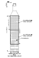
- FIG. 5 is a diagram illustrating an example of a narrow band according to the present embodiment.
- the horizontal axis is the time axis
- the vertical axis is the frequency axis.
- the narrow band is composed of six consecutive physical resource blocks in the frequency domain.
- the terminal device 1 cannot simultaneously receive in a plurality of different narrow bands in a certain slot.
- the terminal device 1 may perform reception in a different narrow band for each slot, for each subframe, or for each set of subframes.
- the terminal device 1 cannot simultaneously transmit in a plurality of different narrow bands in a certain slot.
- the terminal device 1 may perform transmission in a different narrow band for each slot, for each subframe, or for each set of subframes.
- the “PDCCH candidate” and the “MPDCCH candidate” are the same.
- search space “search space”, “PDCCH UE-specific (specific) search space”, and “MPDCCH UE-specific (specific) search space” are the same.
- FIG. 6 is a diagram illustrating an example of a search space in the present embodiment.
- one search space includes PDCCH candidates 60 to 69.
- PDCCH candidate 60 to PDCCH candidate 69 are included in the Xth narrowband.
- frequency hopping may be applied to PDCCH candidates.
- the narrow band including the PDCCH candidate 60 in the first subframe may be different from the narrow band including the PDCCH candidate 60 in the second subframe.
- a gap in the time domain for example, a guard subframe
- the number of resource blocks included in one PDCCH candidate in a certain slot is referred to as an aggregation level (Aggregation Level: AL) of the PDCCH candidate.
- the number of subframes including one PDCCH candidate is referred to as a repetition level (Repetition Level: RL) of the PDCCH candidate.
- the repetition level of PDCCH candidates 60, 61, 62, 63, 64, 65 is expressed as RL 0 .
- the repetition level of the PDCCH candidates 66 and 67 is expressed as RL 1 .
- Repeat level of PDCCH candidates 68 and 69 is represented by RL 2.
- a plurality of PDCCH candidates included in the same search space may overlap.
- the PDCCH candidate 68 overlaps with the PDCCH candidates 60, 61, 62, and 66.
- the plurality of subframes including each of the PDCCH candidates 60, 61, 62, and 66 are a part of the plurality of subframes including the PDCCH candidate 68.
- the two indexes of the two resource blocks included in the PDCCH candidates 60, 61, 62, 66, and 68 are the same.
- the position (subframe and resource block) of the search space in the time domain and / or the frequency domain may be set by an upper layer.
- the position of the search space (subframe and resource block) in the time domain and / or frequency domain may be set by the terminal apparatus 1 based on the upper layer message (RRC message) received from the base station apparatus 3. Good.
- the physical channel may not be included in a subframe that satisfies a predetermined condition.
- a plurality of subframes including a physical channel and “the number of subframes including a physical channel” may be defined in consideration of a subframe that satisfies the predetermined condition. It may be defined without considering subframes that satisfy the condition.
- PDCCH candidates may not be included in subframes that satisfy the predetermined condition.
- the repetition level of PDCCH candidates may be defined without considering a subframe that satisfies the predetermined condition. For example, when a certain PDCCH candidate is included in subframe 1 to subframe 10 and two subframes out of subframe 1 to subframe 10 satisfy a predetermined condition, the repetition level of the certain PDCCH candidate is 10 It may be.
- the repetition level of PDCCH candidates may be defined in consideration of subframes that satisfy the predetermined condition. For example, when a certain PDCCH candidate is included in subframe 1 to subframe 10 and two subframes out of subframe 1 to subframe 10 satisfy a predetermined condition, the repetition level of the certain PDCCH candidate is 8 It may be.
- the predetermined condition may include a part or all of the following conditions (a) to (d).
- the conditions included in the predetermined conditions are not limited to the conditions (a) to (d), and different conditions from the conditions (a) to (d) may be used. A part of the condition (d) may be used from (a).
- “from the Xth subframe” includes the Xth subframe. In the present embodiment, “up to the Yth subframe” includes the Yth subframe.
- the DRX functionality is set by the upper layer (RRC) and processed by MAC.
- the DRX function controls the PDCCH monitoring activity of the terminal device 1 for the C-RNTI and SPS C-RNTI of the terminal device 1.
- the DRX function controls the monitoring activity of the terminal device 1 for the PDCCH used for transmission of the DCI format to which the CRC parity bit scrambled by the C-RNTI or the SPS C-RNTI of the terminal device 1 is added.
- the terminal device 1 may monitor the PDCCH discontinuously using the DRX operation described below. In other cases, the terminal device 1 may continuously monitor the PDCCH.
- the upper layer controls the DRX operation by setting the following timers and the value of drxStartOffset. Whether drxShortCycleTimer and shortDRX-Cycle are set is optional in the upper layer (RRC).
- the terminal device 1 may set the values of onDurationTimer, drx-InactivityTimer, drx-RetransmissionTimer, longDRX-Cycle, drxShortCycleTimer, shortDRX-Cycle, and drxStartOffset based on the received RRC message.
- OnDurationTimer indicates the number of consecutive PDCCH subframes from the beginning of the DRX cycle.
- Drx-InactivityTimer indicates the number of consecutive PDCCH subframes after the subframe to which the PDCCH instructing initial transmission of uplink data or downlink data to the terminal device 1 is mapped.
- Drx-RetransmissionTimer indicates the maximum number of consecutive PDCCH subframes for downlink retransmission expected by the terminal device 1. The same value of drx-RetransmissionTimer is applied to all serving cells.
- the DRX cycle indicates a repetition period of on duration (On Duration).
- On Duration The on-duration period is followed by a period during which inactivity of PDCCH monitoring of the terminal device 1 for the C-RNTI and SPS C-RNTI of the terminal device 1 is possible.
- DrxShortCycleTimer indicates the number of consecutive subframes that the terminal device 1 follows the short DRX cycle.
- DrxStartOffset indicates the subframe in which the DRX cycle starts.
- the HARQ RTT timer corresponding to the downlink HARQ process is managed for each downlink HARQ process in relation to the start of the drx-RetransmissionTimer.
- the HARQ RTT timer corresponding to the downlink HARQ process indicates a minimum interval from transmission of downlink data to retransmission of the downlink data. That is, the HARQ RTT timer corresponding to the downlink HARQ process indicates the minimum amount of subframes before downlink HARQ retransmission is expected by the terminal device 1.
- one downlink HARQ process controls HARQ of one downlink data (transport block). Note that one downlink HARQ process may control two downlink data.
- the active time may include a period that satisfies at least one of the following conditions (e) to (i).
- condition used for determining whether or not a certain period is included in the active time is not limited to the condition (i) to the condition (i), but is different from the condition (e) to the condition (i).
- Conditions may be used, or a part of the conditions (i) to (i) may be used.
- timer Once the timer starts, it is running until the timer is stopped or the timer expires. Otherwise, the timer is not running. If the timer is not running, the timer may be started. If the timer is running, the timer may be restarted. The timer is always started or restarted from the initial value of the timer.
- the preamble is a random access procedure message 1 and is transmitted by PRACH.
- the preamble not selected by the terminal device 1 is related to the contention based random access procedure.
- the random access response is message 2 of the random access procedure and is transmitted by PDSCH.
- the base station device 3 transmits a random access response to the received preamble.
- the terminal device 1 that is executing the contention based random access procedure transmits the message 3 after receiving the random access response.
- the terminal device 1 monitors the PDCCH related to the message 4 after the message 3 is transmitted.
- Mac-ContentionResolutionTimer indicates the number of consecutive subframes in which the terminal device 1 monitors the PDCCH after the message 3 is transmitted.
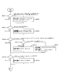
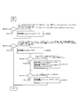
- FIGS. 8 and 9 are flowcharts showing an example of the DRX operation in the present embodiment.
- the terminal device 1 performs a DRX operation based on the flowcharts of FIGS. 8 and 9 for each of the subframes.
- the terminal device 1 If the HARQ RTT timer corresponding to the downlink HARQ process expires in this subframe and the HARQ process data corresponding to the HARQ RTT timer is not successfully decoded (S800), the terminal device 1 The drx-RetransmissionTimer for the downlink HARQ process corresponding to the HARQHARTT timer is started (S802), and the process proceeds to S804. In other cases (S800), the terminal device 1 proceeds to S804.
- the terminal device 1 stops onDurationTimer and drx-InactivityTimer (S806), and proceeds to S808. In other cases (S804), the terminal device 1 proceeds to S808.
- the terminal device 1 proceeds to S810. In other cases (S808), the terminal device 1 proceeds to S816.
- the terminal device 1 uses the long DRX cycle (S812), and proceeds to S816. If the short DRX cycle (shortDRX-Cycle) is set (S810), the terminal device 1 starts or restarts the drxShortCycleTimer, uses the short DRX cycle (S814), and proceeds to S816.
- the terminal device 1 uses the long DRX cycle (S818), and proceeds to S900 of FIG. In other cases (S816), the terminal device 1 proceeds to S900 in FIG.
- the terminal device 1 monitors the PDCCH in this subframe (906), and proceeds to S908.
- All subframes are PDCCH subframes for one FDD serving cell.
- the terminal device 1 and the base station device 3 identify the PDCCH subframe based on the UL-DL configuration for the TDD serving cell.
- the terminal apparatus 1 that communicates with the base station apparatus 3 using one TDD serving cell, and the base station apparatus 3 uses a UL sub-frame setting corresponding to the serving cell, or a subframe including a DwPTS. Is specified (selected, determined) as a PDCCH subframe.
- Half duplex FDD operations include type A half duplex FDD operations and type B half duplex FDD operations.
- the terminal device 1 may transmit information indicating whether or not the type A half-duplex FDD is supported in the FDD band to the base station device 3.
- the terminal device 1 may transmit information indicating whether to support type B half-duplex FDD in the FDD band to the base station device 3.
- the terminal device 1 cannot simultaneously perform uplink transmission and downlink reception.
- the subframe immediately before the subframe in which the terminal device 1 performs uplink transmission and the subframe immediately after the subframe in which the mobile station device 1 performs uplink transmission Each is a half-duplex guard subframe.
- the terminal device 1 cannot simultaneously perform uplink transmission and downlink reception.
- the terminal device 1 cannot receive the downlink in the subframe immediately before the subframe in which uplink transmission is performed.
- the terminal device 1 cannot receive downlink in a subframe immediately after a subframe in which uplink transmission is performed.
- the measurement gap is a time interval for the terminal device 1 to measure different frequency cells and / or different RAT (Radio Access Technology).
- the base station device 3 transmits information indicating the measurement gap period to the terminal device 1.
- the terminal device 1 sets the measurement gap period based on the information.
- the terminal device 1 ends the DRX operation for this subframe. That is, if at least one of the conditions (j) to (n) is not satisfied, the terminal device 1 may not monitor the PDCCH in this subframe.
- the conditions used in S904 are not limited to the conditions (j) to (n). In S904, different conditions from the conditions (j) to (n) may be used, or the conditions (j ) To a part of the condition (n) may be used.
- the terminal device 1 If the downlink assignment or uplink grant received via the PDCCH instructs the initial transmission of the downlink or uplink (S914), the terminal device 1 starts or restarts the drx-InactivityTimer (S914). Then, the DRX operation for this subframe is terminated. In other cases (S912), the terminal device 1 ends the DRX operation for this subframe.
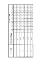
- Some subframes among a plurality of subframes including the PDCCH candidate 240 are not included in the active time, and the remaining subframes are included in the active time.
- the first subframe (T370) among the plurality of subframes including the PDCCH candidate 240 is not included in the active time.
- the terminal device 1 may not monitor the PDCCH candidate 240 based on the fact that the first subframe (T370) among the plurality of subframes including the PDCCH candidate 240 is not included in the active time.
- the first subframe (T372) among the plurality of subframes including the PDCCH candidate 242 is included in the active time.
- the terminal device 1 may monitor the PDCCH candidate 242 based on the fact that the first subframe (T372) among the plurality of subframes including the PDCCH candidate 242 is included in the active time.
- the active time may include a plurality of subframes including the PDCCH candidate 242.
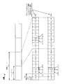
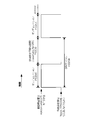
- FIG. 11 is a diagram illustrating an example of PUCCH transmission in the present embodiment.
- PUCCH 250 is included from subframe n to subframe n + Y.
- PUCCH 250 is used for periodic CQI reporting.
- the terminal device 1 may receive information indicating the PUCCH resource used for periodic CQI reporting from the base station device 3.
- the information indicating the PUCCH resource used for periodic CQI reporting may indicate at least a subframe in which the PUCCH used for periodic CQI reporting is arranged.
- the terminal device 1 may receive, from the base station device 3, information (RRC message) instructing the terminal device 1 to set up or release an upper layer parameter / CQI masking (cqi-Mask).
- RRC message information instructing the terminal device 1 to set up or release an upper layer parameter / CQI masking (cqi-Mask).
- the upper layer parameter / CQI masking (cqi-Mask) is not set by the upper layer, and the transmitted scheduling request 251 and / or received information until subframe n-X.
- subframe n is changed to subframe n + Y regardless of whether subframe n + 1 to subframe n + Y is included in the active time.
- the CQI may not be reported on the included PUCCH 250.
- X may be determined in advance by a specification or the like. For example, X is 5.
- the upper layer parameter / CQI masking (cqi-Mask) is not set by the upper layer, and the transmitted scheduling request 251 and / or received information until subframe n-X.
- the transmitted scheduling request 251 and / or received information until subframe n-X.
- subframe n to subframe n + Y are included regardless of whether subframe n + 1 to subframe n + Y are included in the active time.
- CQI may be reported on the PUCCH 250.
- the upper layer parameter / CQI masking (cqi-Mask) is set by the upper layer, and the transmitted scheduling request 251 and / or the received information 252 until subframe nX. If it is inferred that onDurationTimer is not running in subframe n, it is included in subframe n to subframe n + Y regardless of whether onDurationTimer is running from subframe n + 1 to subframe n + Y. PQCH 250 may not report CQI.
- the upper layer parameter / CQI masking (cqi-Mask) is set by the upper layer, and the transmitted scheduling request 251 and / or the received information 252 until subframe nX.
- onDurationTimer When it is inferred that onDurationTimer is running in subframe n, it is included in subframe n to subframe n + Y regardless of whether onDurationTimer is running from subframe n + 1 to subframe n + Y.
- CQI may be reported on PUCCH 250.
- the terminal device 1 may apply any of the above-described examples to the CQI report in the PUCCH 250 regardless of whether the upper layer parameter / CQI masking (cqi-Mask) is set by the upper layer. .
- the terminal device 1 determines whether a part or all of the subframe m to the subframe m + Z is included in the active time, and the onDurationTimer is set to a part or all of the subframe m to the subframe m + Z.
- HARQ-ACK is transmitted on the PUCCH included from subframe m to subframe m + Z regardless of whether or not it is running.
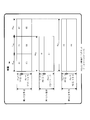
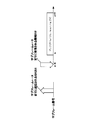
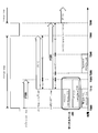
- FIG. 12 is a diagram showing an example of a setting method of drx-InactivityTimer and HARQ RTT timer in the present embodiment.
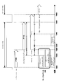
- FIG. 13 is a diagram illustrating another example of the setting method of drx-InactivityTimer and HARQ RTT timer in the present embodiment. Note that the example of FIG. 12 or the example of FIG. 13 may be applied to only one of drx-InactivityTimer and HARQ RTT timer. Different examples may be applied to each of drx-InactivityTimer and HARQHARTT timer.
- the terminal device 1 sets (i) drx-InactivityTimer between A and B in the last subframe including the detected PDCCH 220 or the next subframe after the last subframe. Set to sum, (ii) start drx-InactivityTimer, (iii) set HARQ RTT timer to the sum of A, C, D and E, and (iv) start HARQ RTT timer.
- the value of A is (i) the difference between the number of detected subframes including the PDCCH 220 and the number of subframes including the PDCCH candidate 210, and (ii) the number of subframes including the PDCCH candidate 200 that detected the PDCCH 220. And (iii) the difference between the repetition level of the PDCCH candidate 200 and the repetition level of the PDCCH candidate 210, or (iv) the last subframe including the detected PDCCH 220. It is given by the difference of the last subframe in which the PDCCH candidate 210 is included.
- B value is given by higher layers.
- the value of B is given by higher layer parameters.
- the terminal device 1 may receive an upper layer parameter used to indicate the value of B from the base station device 3.
- the value of E is given by the upper layer.
- the value of E is given by higher layer parameters.
- the terminal device 1 may receive an upper layer parameter used to indicate the value of E from the base station device 3.
- the drx-InactivityTimer is the same subframe in both the case where the terminal device 1 detects the PDCCH 220 using the PDCCH candidate 200 and the case where the terminal device 1 detects the PDCCH 220 using the PDCCH candidate 210. It expires at (time T350) and the HARQ RTT timer expires in the same subframe (time T360). Therefore, by using the method of the example of FIG. 12 and the example of FIG. 13, the terminal device 1 could not recognize whether the detected PDCCH 220 was transmitted by the PDCCH candidate 200 or the PDCCH candidate 210. Even if the terminal device 1 uses the example of FIG. 12 or the example of FIG.
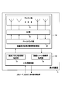
- FIG. 14 is a schematic block diagram showing the configuration of the terminal device 1 of the present embodiment.
- the terminal device 1 includes a wireless transmission / reception unit 10 and an upper layer processing unit 14.
- the wireless transmission / reception unit 10 includes an antenna unit 11, an RF (Radio Frequency) unit 12, and a baseband unit 13.
- the upper layer processing unit 14 includes a medium access control layer processing unit 15 and a radio resource control layer processing unit 16.
- the wireless transmission / reception unit 10 is also referred to as a transmission unit, a reception unit, or a physical layer processing unit.
- the medium access control layer processing unit 15 included in the upper layer processing unit 14 performs processing of the medium access control layer.
- the medium access control layer processing unit 15 performs HARQ control based on various setting information / parameters managed by the radio resource control layer processing unit 16.
- the medium access control layer processing unit 15 manages a plurality of HARQ entities, a plurality of HARQ processes, and a plurality of HARQ buffers.
- the medium access control layer processing unit 15 specifies (selects or determines) a PDCCH subframe.
- the medium access control layer processing unit 15 performs DRX processing based on the PDCCH subframe.
- the medium access control layer processing unit 15 manages a timer related to DRX based on the PDCCH subframe.
- the medium access control layer processing unit 15 instructs the radio transmission / reception unit 10 to monitor the PDCCH in the subframe. Monitoring the PDCCH means attempting to decode the PDCCH according to a certain DCI format.
- the radio resource control layer processing unit 16 included in the upper layer processing unit 14 performs processing of the radio resource control layer.
- the radio resource control layer processing unit 16 manages various setting information / parameters of the own device.
- the radio resource control layer processing unit 16 sets various setting information / parameters based on the RRC layer signal received from the base station apparatus 3. That is, the radio resource control layer processing unit 16 sets various setting information / parameters based on information indicating various setting information / parameters received from the base station apparatus 3.
- the wireless transmission / reception unit 10 performs physical layer processing such as modulation, demodulation, encoding, and decoding.
- the radio transmission / reception unit 10 separates, demodulates, and decodes the signal received from the base station apparatus 3 and outputs the decoded information to the upper layer processing unit 14.
- the radio transmission / reception unit 10 generates a transmission signal by modulating and encoding data, and transmits the transmission signal to the base station apparatus 3.
- the RF unit 12 converts the signal received via the antenna unit 11 into a baseband signal by orthogonal demodulation (down-conversion: down covert), and removes unnecessary frequency components.
- the RF unit 12 outputs the processed analog signal to the baseband unit.
- the baseband unit 13 performs inverse fast Fourier transform (Inverse Fastier Transform: IFFT) to generate an SC-FDMA symbol, adds a CP to the generated SC-FDMA symbol, and converts a baseband digital signal into Generating and converting a baseband digital signal to an analog signal.
- IFFT inverse fast Fourier transform
- the baseband unit 13 outputs the converted analog signal to the RF unit 12.
- the RF unit 12 removes an extra frequency component from the analog signal input from the baseband unit 13 using a low-pass filter, up-converts the analog signal to a carrier frequency, and transmits the signal via the antenna unit 11. To do.
- the RF unit 12 amplifies power. Further, the RF unit 12 may have a function of controlling transmission power.
- the RF unit 12 is also referred to as a transmission power control unit.
- FIG. 15 is a schematic block diagram showing the configuration of the base station apparatus 3 of the present embodiment.
- the base station apparatus 3 includes a radio transmission / reception unit 30 and an upper layer processing unit 34.
- the wireless transmission / reception unit 30 includes an antenna unit 31, an RF unit 32, and a baseband unit 33.
- the upper layer processing unit 34 includes a medium access control layer processing unit 35 and a radio resource control layer processing unit 36.
- the wireless transmission / reception unit 30 is also referred to as a transmission unit, a reception unit, or a physical layer processing unit.
- the upper layer processing unit 34 includes a medium access control (Medium Access Control: MAC) layer, a packet data integration protocol (Packet Data Convergence Protocol: PDCP) layer, a radio link control (Radio Link Control: RLC) layer, a radio resource control (Radio). Resource (Control: RRC) layer processing.
- Medium Access Control Medium Access Control: MAC
- PDCP Packet Data Convergence Protocol
- RLC Radio Link Control
- Radio Radio Resource
- Radio Control
- the medium access control layer processing unit 35 included in the upper layer processing unit 34 performs processing of the medium access control layer.
- the medium access control layer processing unit 15 performs HARQ control based on various setting information / parameters managed by the radio resource control layer processing unit 16.
- the medium access control layer processing unit 15 generates ACK / NACK and HARQ information for uplink data (UL-SCH).
- ACK / NACK and HARQ information for uplink data (UL-SCH) are transmitted to the terminal device 1 by PHICH or PDCCH.
- the radio resource control layer processing unit 36 included in the upper layer processing unit 34 performs processing of the radio resource control layer.
- the radio resource control layer processing unit 36 generates downlink data (transport block), system information, RRC message, MAC CE (Control Element), etc. arranged in the physical downlink shared channel, or acquires it from the upper node. , Output to the wireless transceiver 30.
- the radio resource control layer processing unit 36 manages various setting information / parameters of each terminal device 1.
- the radio resource control layer processing unit 36 may set various setting information / parameters for each terminal device 1 via an upper layer signal. That is, the radio resource control layer processing unit 36 transmits / notifies information indicating various setting information / parameters.
- the first timer includes at least a value of a first higher layer parameter and Is set based on a first value and the first timer is started in the second subframe, wherein the first value is the number of subframes including at least the first PDCCH candidate. And based on the number of subframes in which the second PDCCH candidate is included.
- the receiving unit 10 receives information indicating the number of the first subframe or the position of the first subframe.
- the terminal device 1 when intermittent reception is set, includes a plurality of PDCCH (Physical Downlink Control Control CHannel) candidate sets during the active time.
- Each of the plurality of PDCCH candidates includes one or a plurality of first PDCCHs, wherein the active time includes a period during which a first timer (drx-InactivityTimer) is running.
- Each of the one or more second PDCCH candidates is transmitted from the first subframe to a third subframe after the second subframe.
- the first timer is based on at least a value of a first higher layer parameter. Set, and the first timer is started in the third subframe.
- the receiving unit 10 receives the information indicating the number of the first subframe or the position of the first subframe. .
- the terminal device 1 when intermittent reception is set, includes a plurality of PDCCHs in a set of PDCCH (Physical Downlink Control CHannel) candidates during an active time.
- PDCCH Physical Downlink Control CHannel
- a first timer is started, and the plurality of PDCCH candidates includes one or more first PDCCH candidates and one or more second PDCCH candidates, and the one or more first PDCCH candidates
- Each of the PDCCH candidates is included from the first subframe to the second subframe, and the one or more second PDCCHs are included.
- Each complement is included from the first subframe to a third subframe after the second subframe, and the PDCCH is one of the one or more first PDCCH candidates.
- the second timer is set based on at least the value of the first higher layer parameter, the first value, and the second value, and the second timer in the second subframe
- the first value is determined based on at least the number of subframes including the first PDCCH candidate and the number of subframes including the second PDCCH candidate.
- the value of at least (I) information included in the PDCCH detected in the first PDCCH candidate, and / or (II) the first PDCCH candidate Based on the number of subframes included.
- the receiving unit 10 receives information indicating the number of the first subframe or the position of the first subframe.
- the terminal device 1 when discontinuous reception is set, includes a plurality of PDCCH (Physical Downlink Control CHannel) candidate sets during the active time.
- PDCCH Physical Downlink Control Control CHannel
- a first timer is started, and the plurality of PDCCH candidates includes one or more first PDCCH candidates and one or more second PDCCH candidates, and the one or more first PDCCH candidates
- Each of the PDCCH candidates is included from the first subframe to the second subframe, and the one or more second PDCCHs are included.
- Each complement is included from the first subframe to a third subframe after the second subframe, and the PDCCH is one of the one or more first PDCCH candidates.
- the second timer (HARQ RTT timer) is set based on at least the value of the first higher layer parameter and the first value, and the second timer is set in the third subframe.
- the first value includes at least (I) information included in the PDCCH detected in the first PDCCH candidate and / or (II) the first PDCCH candidate. Based on the number of subframes
- the transmitter 10 is configured such that the first upper layer parameter is set by the upper layer and the information received up to the first subframe, and / or Considering the transmitted scheduling request, if the first timer (onDurationTimer) is not running in the first subframe, the first subframe is followed by the second subframe from the subframe next to the first subframe.
- the CQI is not reported on the PUCCH included in the second subframe from the first subframe regardless of whether or not the timer (onDurationTimer) of 1 is running.
- the second PUCCH for CQI reporting is included from the third subframe to the fourth subframe, and the transmitting unit 10
- the third subframe is set to the active time. If included, the third subframe to the fourth subframe, regardless of whether the active time includes the next subframe from the third subframe to the fourth subframe.
- the CQI is reported on the second PUCCH included.
- the transmission unit 10 is configured to receive information received in the first sub-frame until the first upper layer parameter is set by the upper layer, and / or Considering the transmitted scheduling request, when the first timer (onDurationTimer) is running in the third subframe, the second subframe from the next subframe to the fourth subframe is used. Regardless of whether or not one timer (onDurationTimer) is running, the CQI is reported on the second PUCCH included in the fourth subframe from the third subframe.
- the third PUCCH for transmission of HARQ-ACK (Hybrid Automatic Repeat reQuest ACKnowledgement) is included from the fifth subframe to the sixth subframe, Regardless of whether or not part or all of the fifth subframe to the sixth subframe is included in the active time, the transmitter 10 performs the fifth subframe to the sixth subframe.
- the HARQ-ACK is transmitted on the third PUCCH included in the subframe.
- the terminal apparatus 1 can communicate with the base station apparatus 3 efficiently.
- a program that operates in the base station device 3 and the terminal device 1 related to the present invention is a program that controls a CPU (Central Processing Unit) or the like (a computer is functioned) so as to realize the functions of the above-described embodiments related to the present invention Program).
- Information handled by these devices is temporarily stored in RAM (Random Access Memory) during processing, and then stored in various ROMs such as Flash ROM (Read Only Memory) and HDD (Hard Disk Drive). Reading, correction, and writing are performed by the CPU as necessary.
- the “computer system” here is a computer system built in the terminal device 1 or the base station device 3 and includes hardware such as an OS and peripheral devices.
- the “computer-readable recording medium” refers to a storage device such as a flexible medium, a magneto-optical disk, a portable medium such as a ROM or a CD-ROM, and a hard disk incorporated in a computer system.
- the “computer-readable recording medium” is a medium that dynamically holds a program for a short time, such as a communication line when transmitting a program via a network such as the Internet or a communication line such as a telephone line,
- a volatile memory inside a computer system serving as a server or a client may be included and a program that holds a program for a certain period of time.
- the program may be a program for realizing a part of the functions described above, and may be a program capable of realizing the functions described above in combination with a program already recorded in a computer system.
- the base station device 3 in the above-described embodiment can be realized as an aggregate (device group) composed of a plurality of devices.
- Each of the devices constituting the device group may include a part or all of each function or each functional block of the base station device 3 according to the above-described embodiment.
- the device group only needs to have one function or each function block of the base station device 3.
- the terminal device 1 according to the above-described embodiment can also communicate with the base station device as an aggregate.
Landscapes
- Engineering & Computer Science (AREA)
- Signal Processing (AREA)
- Computer Networks & Wireless Communication (AREA)
- Mobile Radio Communication Systems (AREA)
Abstract
Description
本願は、2015年6月19日に、日本に出願された特願2015-123365号に基づき優先権を主張し、その内容をここに援用する。
・PUCCH(Physical Uplink Control Channel)
・PUSCH(Physical Uplink Shared Channel)
・PRACH(Physical Random Access Channel)
・上りリンク参照信号(Uplink Reference Signal: UL RS)
・PBCH(Physical Broadcast Channel)
・PCFICH(Physical Control Format Indicator Channel)
・PHICH(Physical Hybrid automatic repeat request Indicator Channel)
・PDCCH(Physical Downlink Control Channel)
・EPDCCH(Enhanced Physical Downlink Control Channel)
・MPDCCH(Machine type communication Physical Downlink Control Channel)
・PDSCH(Physical Downlink Shared Channel)
・PMCH(Physical Multicast Channel)
・同期信号(Synchronization signal: SS)
・下りリンク参照信号(Downlink Reference Signal: DL RS)
・CRS(Cell-specific Reference Signal)
・PDSCHに関連するURS(UE-specific Reference Signal)
・EPDCCHに関連するDMRS(Demodulation Reference Signal)
・NZP CSI-RS(Non-Zero Power Chanel State Information - Reference Signal)
・ZP CSI-RS(Zero Power Chanel State Information - Reference Signal)
・MBSFN RS(Multimedia Broadcast and Multicast Service over Single Frequency Network Reference signal)
・PRS(Positioning Reference Signal)
・下りリンクサブフレーム
・上りリンクサブフレーム
・スペシャルサブフレーム
・条件(a):サブフレームがMBSFNサブフレームとして予約されている
・条件(b):TDDにおいて、サブフレームが上りリンクサブフレームである
・条件(c):サブフレームがPDCCH候補に適用される周波数ホッピングのためのギャップ(ガードサブフレーム)である
・条件(d):サブフレームが、設定された測定ギャップの一部である
・drx-InactivityTimer
・drx-RetransmissionTimer(ブロードキャストプロセスに対する下りリンクHARQプロセスを除いて下りリンクHARQプロセス毎に1つ)
・longDRX-Cycle
・HARQ RTT(Round Trip Time)タイマー(下りリンクHARQプロセス毎に1つ)
・drxShortCycleTimer(オプショナル)
・shortDRX-Cycle(オプショナル)
・条件(f):スケジューリング要求がPUCCHで送信され、そして、ペンディングされている
・条件(g):同期HARQに対して、ペンディングHARQ再送信に対する上りリンクグラントが送信される可能性があり、そして、対応するHARQバッファにデータがある
・条件(h):端末装置1によって選択されていないプリアンブルに対するランダムアクセスレスポンスの受信に成功した後に、端末装置1のC-RNTIをともない、そして、初期送信を指示するPDCCHをずっと受信していない
・条件(i):端末装置1が、複数のサブフレームに含まれるPDCCH候補をモニタしている
・条件(k):このサブフレームがPDCCHサブフレームである
・条件(l):このサブフレームが半二重FDD動作の端末装置1に対する上りリンク送信に必要でない
・条件(m):サブフレームが半二重ガードサブフレームではない
・条件(n):このサブフレームが設定された測定ギャップ(measurement gap)の一部ではない
3 基地局装置
10 無線送受信部
11 アンテナ部
12 RF部
13 ベースバンド部
14 上位層処理部
15 媒体アクセス制御層処理部
16 無線リソース制御層処理部
30 無線送受信部
31 アンテナ部
32 RF部
33 ベースバンド部
34 上位層処理部
35 媒体アクセス制御層処理部
36 無線リソース制御層処理部
Claims (4)
- チャネル状態情報、および、HARQ-ACKを含む上りリンク制御情報をPUCCHで送信する送信部と、
MPDCCHのモニタリングを制御するDRX機能を実行する媒体アクセス制御層処理部と、を備え、
CQIマスキングが上位層によって設定されておらず、尚且つ、サブフレームn-5までに送信したスケジューリングリクエスト、および、前記サブフレームn-5までに受信した情報を考慮すると、サブフレームnがアクティブタイムに含まれると推量される場合、サブフレームn+1がアクティブタイムに含まれるかいなかに関わらず、前記チャネル状態情報は、前記サブフレームn、および、前記サブフレームn+1におけるPUCCHを用いて送信される
端末装置。 - 前記サブフレームnが前記アクティブタイムに含まれないと推量される場合、前記チャネル状態情報は、前記サブフレームnにおけるPUCCHを用いて送信されない
請求項1の端末装置。 - 端末装置に用いられる通信方法であって、
チャネル状態情報、および、HARQ-ACKを含む上りリンク制御情報をPUCCHで送信し、
MPDCCHのモニタリングを制御するDRX機能を実行し、
CQIマスキングが上位層によって設定されておらず、尚且つ、サブフレームn-5までに送信したスケジューリングリクエスト、および、前記サブフレームn-5までに受信した情報を考慮すると、サブフレームnがアクティブタイムに含まれると推量される場合、サブフレームn+1がアクティブタイムに含まれるかいなかに関わらず、前記チャネル状態情報は、前記サブフレームn、および、前記サブフレームn+1におけるPUCCHを用いて送信される
通信方法。 - 端末装置に実装される集積回路であって、
チャネル状態情報、および、HARQ-ACKを含む上りリンク制御情報をPUCCHで送信する送信回路と、
MPDCCHのモニタリングを制御するDRX機能を実行する媒体アクセス制御層処理回路と、を備え、
CQIマスキングが上位層によって設定されておらず、尚且つ、サブフレームn-5までに送信したスケジューリングリクエスト、および、前記サブフレームn-5までに受信した情報を考慮すると、サブフレームnがアクティブタイムに含まれると推量される場合、サブフレームn+1がアクティブタイムに含まれるかいなかに関わらず、前記チャネル状態情報は、前記サブフレームn、および、前記サブフレームn+1におけるPUCCHを用いて送信される
集積回路。
Priority Applications (6)
| Application Number | Priority Date | Filing Date | Title |
|---|---|---|---|
| US15/737,345 US10271234B2 (en) | 2015-06-19 | 2016-06-15 | Terminal device, communication method, and integrated circuit |
| AU2016278313A AU2016278313B2 (en) | 2015-06-19 | 2016-06-15 | Terminal device, communication method, and integrated circuit |
| JP2017525250A JP6967450B2 (ja) | 2015-06-19 | 2016-06-15 | 端末装置、通信方法、および、集積回路 |
| EP16811635.8A EP3313121B1 (en) | 2015-06-19 | 2016-06-15 | Terminal device, communication method, and integrated circuit |
| MYPI2017001872A MY189584A (en) | 2015-06-19 | 2016-06-15 | Terminal device, communication method, and integrated circuit |
| CN201680034361.5A CN107637139B (zh) | 2015-06-19 | 2016-06-15 | 终端装置、通信方法以及集成电路 |
Applications Claiming Priority (2)
| Application Number | Priority Date | Filing Date | Title |
|---|---|---|---|
| JP2015-123365 | 2015-06-19 | ||
| JP2015123365 | 2015-06-19 |
Publications (1)
| Publication Number | Publication Date |
|---|---|
| WO2016204161A1 true WO2016204161A1 (ja) | 2016-12-22 |
Family
ID=57546673
Family Applications (1)
| Application Number | Title | Priority Date | Filing Date |
|---|---|---|---|
| PCT/JP2016/067733 Ceased WO2016204161A1 (ja) | 2015-06-19 | 2016-06-15 | 端末装置、通信方法、および、集積回路 |
Country Status (7)
| Country | Link |
|---|---|
| US (1) | US10271234B2 (ja) |
| EP (1) | EP3313121B1 (ja) |
| JP (1) | JP6967450B2 (ja) |
| CN (1) | CN107637139B (ja) |
| AU (1) | AU2016278313B2 (ja) |
| MY (1) | MY189584A (ja) |
| WO (1) | WO2016204161A1 (ja) |
Cited By (2)
| Publication number | Priority date | Publication date | Assignee | Title |
|---|---|---|---|---|
| JP2021534681A (ja) * | 2018-08-31 | 2021-12-09 | 華為技術有限公司Huawei Technologies Co., Ltd. | 監視方法およびデバイス |
| JP2021536162A (ja) * | 2018-07-25 | 2021-12-23 | オッポ広東移動通信有限公司Guangdong Oppo Mobile Telecommunications Corp., Ltd. | チャネルモニタリング方法及び装置、端末装置並びにネットワーク装置 |
Families Citing this family (10)
| Publication number | Priority date | Publication date | Assignee | Title |
|---|---|---|---|---|
| US11272467B2 (en) * | 2016-03-30 | 2022-03-08 | Lg Electronics Inc. | Method for transmitting and receiving sidelink signal of UE using GNSS timing in wireless communication system |
| EP3402288B1 (en) * | 2017-05-12 | 2021-02-24 | ASUSTek Computer Inc. | Method and apparatus for improving scheduling in a wireless communication system |
| US11356987B2 (en) * | 2017-09-30 | 2022-06-07 | Samsung Electronics Co., Ltd. | Method and equipment for transmitting uplink control information and setting uplink time advance |
| WO2019095294A1 (zh) * | 2017-11-17 | 2019-05-23 | Oppo广东移动通信有限公司 | 用于侦听pdcch的方法和终端设备 |
| US10772151B2 (en) | 2018-01-05 | 2020-09-08 | Ofinno, Llc | Beam management in discontinuous reception |
| US12082206B2 (en) * | 2018-07-25 | 2024-09-03 | Sony Corporation | Communications system and associated devices for performing communication using control channels of different repetition rates |
| CN111278171B (zh) * | 2019-01-31 | 2022-05-17 | 维沃移动通信有限公司 | 一种非连续接收drx配置方法及终端 |
| CN112543442B (zh) * | 2019-09-20 | 2022-08-19 | 维沃移动通信有限公司 | 非连续接收参数配置方法及设备 |
| CN114390446A (zh) * | 2020-10-20 | 2022-04-22 | 夏普株式会社 | 非连续性接收方法以及用户设备 |
| CN115278664B (zh) * | 2022-07-14 | 2025-09-02 | 中国信息通信研究院 | 一种无线设备认证指示方法和设备 |
Citations (1)
| Publication number | Priority date | Publication date | Assignee | Title |
|---|---|---|---|---|
| WO2014146736A1 (en) * | 2013-03-20 | 2014-09-25 | Panasonic Intellectual Property Corporation Of America | Deterministic ue behaviour for csi/srs reporting during drx |
Family Cites Families (5)
| Publication number | Priority date | Publication date | Assignee | Title |
|---|---|---|---|---|
| ES2682321T3 (es) * | 2012-07-09 | 2018-09-20 | Lg Electronics Inc. | Método y aparato para controlar transmisión de enlace ascendente en operación de recepción discontinua en sistema de comunicación inalámbrica |
| KR20140022711A (ko) | 2012-08-14 | 2014-02-25 | 삼성전자주식회사 | 이동통신 시스템에서 핸드 오버를 수행하는 방법 및 장치 |
| US10419990B2 (en) * | 2015-01-16 | 2019-09-17 | Sharp Kabushiki Kaisha | Wireless terminals, base stations, communication systems, communication methods, and integrated circuits |
| CN107710834B (zh) * | 2015-06-19 | 2021-03-23 | 夏普株式会社 | 终端装置、通信方法以及集成电路 |
| CN108377177B (zh) * | 2016-10-17 | 2021-03-02 | 华硕电脑股份有限公司 | 无线通信系统中处置不连续接收操作的方法和设备 |
-
2016
- 2016-06-15 CN CN201680034361.5A patent/CN107637139B/zh active Active
- 2016-06-15 WO PCT/JP2016/067733 patent/WO2016204161A1/ja not_active Ceased
- 2016-06-15 AU AU2016278313A patent/AU2016278313B2/en active Active
- 2016-06-15 EP EP16811635.8A patent/EP3313121B1/en active Active
- 2016-06-15 MY MYPI2017001872A patent/MY189584A/en unknown
- 2016-06-15 JP JP2017525250A patent/JP6967450B2/ja active Active
- 2016-06-15 US US15/737,345 patent/US10271234B2/en active Active
Patent Citations (1)
| Publication number | Priority date | Publication date | Assignee | Title |
|---|---|---|---|---|
| WO2014146736A1 (en) * | 2013-03-20 | 2014-09-25 | Panasonic Intellectual Property Corporation Of America | Deterministic ue behaviour for csi/srs reporting during drx |
Non-Patent Citations (3)
| Title |
|---|
| HUAWEI: "HiSilicon, On Paging transmission for MTC", 3GPP TSG-RAN WG1#81 R1-153239, 25 May 2015 (2015-05-25), XP050970988 * |
| PANASONIC: "Consideration on data channel and associated control channel for MTC", 3GPP TSG- RAN WG1#79 R1-144797, 17 November 2014 (2014-11-17), XP050875864 * |
| See also references of EP3313121A4 * |
Cited By (10)
| Publication number | Priority date | Publication date | Assignee | Title |
|---|---|---|---|---|
| JP2021536162A (ja) * | 2018-07-25 | 2021-12-23 | オッポ広東移動通信有限公司Guangdong Oppo Mobile Telecommunications Corp., Ltd. | チャネルモニタリング方法及び装置、端末装置並びにネットワーク装置 |
| US11765721B2 (en) | 2018-07-25 | 2023-09-19 | Guangdong Oppo Mobile Telecommunications Corp., Ltd. | Channel monitoring method and apparatus, terminal device and network device |
| JP2023156467A (ja) * | 2018-07-25 | 2023-10-24 | オッポ広東移動通信有限公司 | チャネルモニタリング方法及び装置、端末装置並びにネットワーク装置 |
| JP7383690B2 (ja) | 2018-07-25 | 2023-11-20 | オッポ広東移動通信有限公司 | チャネルモニタリング方法及び装置、端末装置並びにネットワーク装置 |
| US12133221B2 (en) | 2018-07-25 | 2024-10-29 | Guangdong Oppo Mobile Telecommunications Corp., Ltd. | Channel monitoring method and apparatus, terminal device and network device |
| JP7608539B2 (ja) | 2018-07-25 | 2025-01-06 | オッポ広東移動通信有限公司 | チャネルモニタリング方法及び装置、端末装置並びにネットワーク装置 |
| JP2021534681A (ja) * | 2018-08-31 | 2021-12-09 | 華為技術有限公司Huawei Technologies Co., Ltd. | 監視方法およびデバイス |
| JP2023179693A (ja) * | 2018-08-31 | 2023-12-19 | 華為技術有限公司 | 監視方法およびデバイス |
| US12052591B2 (en) | 2018-08-31 | 2024-07-30 | Huawei Technologies Co., Ltd. | Monitoring method and device |
| JP7706517B2 (ja) | 2018-08-31 | 2025-07-11 | 華為技術有限公司 | 監視方法およびデバイス |
Also Published As
| Publication number | Publication date |
|---|---|
| CN107637139A (zh) | 2018-01-26 |
| EP3313121B1 (en) | 2021-07-28 |
| JP6967450B2 (ja) | 2021-11-17 |
| US20180176806A1 (en) | 2018-06-21 |
| EP3313121A4 (en) | 2019-02-13 |
| AU2016278313A1 (en) | 2018-01-18 |
| US10271234B2 (en) | 2019-04-23 |
| AU2016278313B2 (en) | 2020-01-23 |
| JPWO2016204161A1 (ja) | 2018-04-12 |
| EP3313121A1 (en) | 2018-04-25 |
| CN107637139B (zh) | 2021-05-11 |
| MY189584A (en) | 2022-02-18 |
Similar Documents
| Publication | Publication Date | Title |
|---|---|---|
| US10389493B2 (en) | Terminal device, communication method, and integrated circuit | |
| JP6734846B2 (ja) | 端末装置、通信方法、および、集積回路 | |
| JP6666910B2 (ja) | 端末装置、通信方法、および、集積回路 | |
| JP6967450B2 (ja) | 端末装置、通信方法、および、集積回路 | |
| US11039462B2 (en) | Terminal apparatus, base station apparatus, communication method, and integrated circuit | |
| WO2018173885A1 (ja) | 端末装置、基地局装置、通信方法、および、集積回路 | |
| CN104969488A (zh) | 用于在无线电通信系统中设置用于d2d(设备对设备)通信的循环前缀的方法及其设备 | |
| WO2018092844A1 (ja) | 端末装置、基地局装置、通信方法、および、集積回路 |
Legal Events
| Date | Code | Title | Description |
|---|---|---|---|
| 121 | Ep: the epo has been informed by wipo that ep was designated in this application |
Ref document number: 16811635 Country of ref document: EP Kind code of ref document: A1 |
|
| ENP | Entry into the national phase |
Ref document number: 2017525250 Country of ref document: JP Kind code of ref document: A |
|
| WWE | Wipo information: entry into national phase |
Ref document number: 15737345 Country of ref document: US |
|
| NENP | Non-entry into the national phase |
Ref country code: DE |
|
| ENP | Entry into the national phase |
Ref document number: 2016278313 Country of ref document: AU Date of ref document: 20160615 Kind code of ref document: A |
|
| WWE | Wipo information: entry into national phase |
Ref document number: 2016811635 Country of ref document: EP |