WO2016204194A1 - 空気調和装置 - Google Patents
空気調和装置 Download PDFInfo
- Publication number
- WO2016204194A1 WO2016204194A1 PCT/JP2016/067844 JP2016067844W WO2016204194A1 WO 2016204194 A1 WO2016204194 A1 WO 2016204194A1 JP 2016067844 W JP2016067844 W JP 2016067844W WO 2016204194 A1 WO2016204194 A1 WO 2016204194A1
- Authority
- WO
- WIPO (PCT)
- Prior art keywords
- refrigerant
- outdoor
- liquid
- pipe
- expansion valve
- Prior art date
- Legal status (The legal status is an assumption and is not a legal conclusion. Google has not performed a legal analysis and makes no representation as to the accuracy of the status listed.)
- Ceased
Links
Images




Classifications
-
- F—MECHANICAL ENGINEERING; LIGHTING; HEATING; WEAPONS; BLASTING
- F25—REFRIGERATION OR COOLING; COMBINED HEATING AND REFRIGERATION SYSTEMS; HEAT PUMP SYSTEMS; MANUFACTURE OR STORAGE OF ICE; LIQUEFACTION SOLIDIFICATION OF GASES
- F25B—REFRIGERATION MACHINES, PLANTS OR SYSTEMS; COMBINED HEATING AND REFRIGERATION SYSTEMS; HEAT PUMP SYSTEMS
- F25B5/00—Compression machines, plants or systems, with several evaporator circuits, e.g. for varying refrigerating capacity
- F25B5/02—Compression machines, plants or systems, with several evaporator circuits, e.g. for varying refrigerating capacity arranged in parallel
-
- F—MECHANICAL ENGINEERING; LIGHTING; HEATING; WEAPONS; BLASTING
- F25—REFRIGERATION OR COOLING; COMBINED HEATING AND REFRIGERATION SYSTEMS; HEAT PUMP SYSTEMS; MANUFACTURE OR STORAGE OF ICE; LIQUEFACTION SOLIDIFICATION OF GASES
- F25B—REFRIGERATION MACHINES, PLANTS OR SYSTEMS; COMBINED HEATING AND REFRIGERATION SYSTEMS; HEAT PUMP SYSTEMS
- F25B1/00—Compression machines, plants or systems with non-reversible cycle
- F25B1/005—Compression machines, plants or systems with non-reversible cycle of the single unit type
-
- F—MECHANICAL ENGINEERING; LIGHTING; HEATING; WEAPONS; BLASTING
- F24—HEATING; RANGES; VENTILATING
- F24F—AIR-CONDITIONING; AIR-HUMIDIFICATION; VENTILATION; USE OF AIR CURRENTS FOR SCREENING
- F24F11/00—Control or safety arrangements
- F24F11/89—Arrangement or mounting of control or safety devices
-
- F—MECHANICAL ENGINEERING; LIGHTING; HEATING; WEAPONS; BLASTING
- F25—REFRIGERATION OR COOLING; COMBINED HEATING AND REFRIGERATION SYSTEMS; HEAT PUMP SYSTEMS; MANUFACTURE OR STORAGE OF ICE; LIQUEFACTION SOLIDIFICATION OF GASES
- F25B—REFRIGERATION MACHINES, PLANTS OR SYSTEMS; COMBINED HEATING AND REFRIGERATION SYSTEMS; HEAT PUMP SYSTEMS
- F25B41/00—Fluid-circulation arrangements
- F25B41/30—Expansion means; Dispositions thereof
- F25B41/39—Dispositions with two or more expansion means arranged in series, i.e. multi-stage expansion, on a refrigerant line leading to the same evaporator
-
- F—MECHANICAL ENGINEERING; LIGHTING; HEATING; WEAPONS; BLASTING
- F25—REFRIGERATION OR COOLING; COMBINED HEATING AND REFRIGERATION SYSTEMS; HEAT PUMP SYSTEMS; MANUFACTURE OR STORAGE OF ICE; LIQUEFACTION SOLIDIFICATION OF GASES
- F25B—REFRIGERATION MACHINES, PLANTS OR SYSTEMS; COMBINED HEATING AND REFRIGERATION SYSTEMS; HEAT PUMP SYSTEMS
- F25B49/00—Arrangement or mounting of control or safety devices
- F25B49/02—Arrangement or mounting of control or safety devices for compression type machines, plants or systems
-
- F—MECHANICAL ENGINEERING; LIGHTING; HEATING; WEAPONS; BLASTING
- F25—REFRIGERATION OR COOLING; COMBINED HEATING AND REFRIGERATION SYSTEMS; HEAT PUMP SYSTEMS; MANUFACTURE OR STORAGE OF ICE; LIQUEFACTION SOLIDIFICATION OF GASES
- F25B—REFRIGERATION MACHINES, PLANTS OR SYSTEMS; COMBINED HEATING AND REFRIGERATION SYSTEMS; HEAT PUMP SYSTEMS
- F25B2313/00—Compression machines, plants or systems with reversible cycle not otherwise provided for
- F25B2313/027—Compression machines, plants or systems with reversible cycle not otherwise provided for characterised by the reversing means
- F25B2313/02741—Compression machines, plants or systems with reversible cycle not otherwise provided for characterised by the reversing means using one four-way valve
-
- F—MECHANICAL ENGINEERING; LIGHTING; HEATING; WEAPONS; BLASTING
- F25—REFRIGERATION OR COOLING; COMBINED HEATING AND REFRIGERATION SYSTEMS; HEAT PUMP SYSTEMS; MANUFACTURE OR STORAGE OF ICE; LIQUEFACTION SOLIDIFICATION OF GASES
- F25B—REFRIGERATION MACHINES, PLANTS OR SYSTEMS; COMBINED HEATING AND REFRIGERATION SYSTEMS; HEAT PUMP SYSTEMS
- F25B2400/00—Component parts or details not otherwise provided for in this subclass
- F25B2400/13—Economisers
-
- F—MECHANICAL ENGINEERING; LIGHTING; HEATING; WEAPONS; BLASTING
- F25—REFRIGERATION OR COOLING; COMBINED HEATING AND REFRIGERATION SYSTEMS; HEAT PUMP SYSTEMS; MANUFACTURE OR STORAGE OF ICE; LIQUEFACTION SOLIDIFICATION OF GASES
- F25B—REFRIGERATION MACHINES, PLANTS OR SYSTEMS; COMBINED HEATING AND REFRIGERATION SYSTEMS; HEAT PUMP SYSTEMS
- F25B2600/00—Control issues
- F25B2600/25—Control of valves
- F25B2600/2513—Expansion valves
-
- F—MECHANICAL ENGINEERING; LIGHTING; HEATING; WEAPONS; BLASTING
- F25—REFRIGERATION OR COOLING; COMBINED HEATING AND REFRIGERATION SYSTEMS; HEAT PUMP SYSTEMS; MANUFACTURE OR STORAGE OF ICE; LIQUEFACTION SOLIDIFICATION OF GASES
- F25B—REFRIGERATION MACHINES, PLANTS OR SYSTEMS; COMBINED HEATING AND REFRIGERATION SYSTEMS; HEAT PUMP SYSTEMS
- F25B2700/00—Sensing or detecting of parameters; Sensors therefor
- F25B2700/19—Pressures
- F25B2700/193—Pressures of the compressor
- F25B2700/1931—Discharge pressures
-
- F—MECHANICAL ENGINEERING; LIGHTING; HEATING; WEAPONS; BLASTING
- F25—REFRIGERATION OR COOLING; COMBINED HEATING AND REFRIGERATION SYSTEMS; HEAT PUMP SYSTEMS; MANUFACTURE OR STORAGE OF ICE; LIQUEFACTION SOLIDIFICATION OF GASES
- F25B—REFRIGERATION MACHINES, PLANTS OR SYSTEMS; COMBINED HEATING AND REFRIGERATION SYSTEMS; HEAT PUMP SYSTEMS
- F25B2700/00—Sensing or detecting of parameters; Sensors therefor
- F25B2700/19—Pressures
- F25B2700/193—Pressures of the compressor
- F25B2700/1933—Suction pressures
-
- F—MECHANICAL ENGINEERING; LIGHTING; HEATING; WEAPONS; BLASTING
- F25—REFRIGERATION OR COOLING; COMBINED HEATING AND REFRIGERATION SYSTEMS; HEAT PUMP SYSTEMS; MANUFACTURE OR STORAGE OF ICE; LIQUEFACTION SOLIDIFICATION OF GASES
- F25B—REFRIGERATION MACHINES, PLANTS OR SYSTEMS; COMBINED HEATING AND REFRIGERATION SYSTEMS; HEAT PUMP SYSTEMS
- F25B2700/00—Sensing or detecting of parameters; Sensors therefor
- F25B2700/19—Pressures
- F25B2700/195—Pressures of the condenser
-
- F—MECHANICAL ENGINEERING; LIGHTING; HEATING; WEAPONS; BLASTING
- F25—REFRIGERATION OR COOLING; COMBINED HEATING AND REFRIGERATION SYSTEMS; HEAT PUMP SYSTEMS; MANUFACTURE OR STORAGE OF ICE; LIQUEFACTION SOLIDIFICATION OF GASES
- F25B—REFRIGERATION MACHINES, PLANTS OR SYSTEMS; COMBINED HEATING AND REFRIGERATION SYSTEMS; HEAT PUMP SYSTEMS
- F25B2700/00—Sensing or detecting of parameters; Sensors therefor
- F25B2700/19—Pressures
- F25B2700/197—Pressures of the evaporator
-
- F—MECHANICAL ENGINEERING; LIGHTING; HEATING; WEAPONS; BLASTING
- F25—REFRIGERATION OR COOLING; COMBINED HEATING AND REFRIGERATION SYSTEMS; HEAT PUMP SYSTEMS; MANUFACTURE OR STORAGE OF ICE; LIQUEFACTION SOLIDIFICATION OF GASES
- F25B—REFRIGERATION MACHINES, PLANTS OR SYSTEMS; COMBINED HEATING AND REFRIGERATION SYSTEMS; HEAT PUMP SYSTEMS
- F25B2700/00—Sensing or detecting of parameters; Sensors therefor
- F25B2700/21—Temperatures
- F25B2700/2106—Temperatures of fresh outdoor air
-
- F—MECHANICAL ENGINEERING; LIGHTING; HEATING; WEAPONS; BLASTING
- F25—REFRIGERATION OR COOLING; COMBINED HEATING AND REFRIGERATION SYSTEMS; HEAT PUMP SYSTEMS; MANUFACTURE OR STORAGE OF ICE; LIQUEFACTION SOLIDIFICATION OF GASES
- F25B—REFRIGERATION MACHINES, PLANTS OR SYSTEMS; COMBINED HEATING AND REFRIGERATION SYSTEMS; HEAT PUMP SYSTEMS
- F25B2700/00—Sensing or detecting of parameters; Sensors therefor
- F25B2700/21—Temperatures
- F25B2700/2115—Temperatures of a compressor or the drive means therefor
- F25B2700/21151—Temperatures of a compressor or the drive means therefor at the suction side of the compressor
-
- F—MECHANICAL ENGINEERING; LIGHTING; HEATING; WEAPONS; BLASTING
- F25—REFRIGERATION OR COOLING; COMBINED HEATING AND REFRIGERATION SYSTEMS; HEAT PUMP SYSTEMS; MANUFACTURE OR STORAGE OF ICE; LIQUEFACTION SOLIDIFICATION OF GASES
- F25B—REFRIGERATION MACHINES, PLANTS OR SYSTEMS; COMBINED HEATING AND REFRIGERATION SYSTEMS; HEAT PUMP SYSTEMS
- F25B2700/00—Sensing or detecting of parameters; Sensors therefor
- F25B2700/21—Temperatures
- F25B2700/2115—Temperatures of a compressor or the drive means therefor
- F25B2700/21152—Temperatures of a compressor or the drive means therefor at the discharge side of the compressor
-
- F—MECHANICAL ENGINEERING; LIGHTING; HEATING; WEAPONS; BLASTING
- F25—REFRIGERATION OR COOLING; COMBINED HEATING AND REFRIGERATION SYSTEMS; HEAT PUMP SYSTEMS; MANUFACTURE OR STORAGE OF ICE; LIQUEFACTION SOLIDIFICATION OF GASES
- F25B—REFRIGERATION MACHINES, PLANTS OR SYSTEMS; COMBINED HEATING AND REFRIGERATION SYSTEMS; HEAT PUMP SYSTEMS
- F25B2700/00—Sensing or detecting of parameters; Sensors therefor
- F25B2700/21—Temperatures
- F25B2700/2116—Temperatures of a condenser
- F25B2700/21163—Temperatures of a condenser of the refrigerant at the outlet of the condenser
-
- F—MECHANICAL ENGINEERING; LIGHTING; HEATING; WEAPONS; BLASTING
- F25—REFRIGERATION OR COOLING; COMBINED HEATING AND REFRIGERATION SYSTEMS; HEAT PUMP SYSTEMS; MANUFACTURE OR STORAGE OF ICE; LIQUEFACTION SOLIDIFICATION OF GASES
- F25B—REFRIGERATION MACHINES, PLANTS OR SYSTEMS; COMBINED HEATING AND REFRIGERATION SYSTEMS; HEAT PUMP SYSTEMS
- F25B2700/00—Sensing or detecting of parameters; Sensors therefor
- F25B2700/21—Temperatures
- F25B2700/2117—Temperatures of an evaporator
- F25B2700/21171—Temperatures of an evaporator of the fluid cooled by the evaporator
-
- F—MECHANICAL ENGINEERING; LIGHTING; HEATING; WEAPONS; BLASTING
- F25—REFRIGERATION OR COOLING; COMBINED HEATING AND REFRIGERATION SYSTEMS; HEAT PUMP SYSTEMS; MANUFACTURE OR STORAGE OF ICE; LIQUEFACTION SOLIDIFICATION OF GASES
- F25B—REFRIGERATION MACHINES, PLANTS OR SYSTEMS; COMBINED HEATING AND REFRIGERATION SYSTEMS; HEAT PUMP SYSTEMS
- F25B2700/00—Sensing or detecting of parameters; Sensors therefor
- F25B2700/21—Temperatures
- F25B2700/2117—Temperatures of an evaporator
- F25B2700/21174—Temperatures of an evaporator of the refrigerant at the inlet of the evaporator
-
- F—MECHANICAL ENGINEERING; LIGHTING; HEATING; WEAPONS; BLASTING
- F25—REFRIGERATION OR COOLING; COMBINED HEATING AND REFRIGERATION SYSTEMS; HEAT PUMP SYSTEMS; MANUFACTURE OR STORAGE OF ICE; LIQUEFACTION SOLIDIFICATION OF GASES
- F25B—REFRIGERATION MACHINES, PLANTS OR SYSTEMS; COMBINED HEATING AND REFRIGERATION SYSTEMS; HEAT PUMP SYSTEMS
- F25B2700/00—Sensing or detecting of parameters; Sensors therefor
- F25B2700/21—Temperatures
- F25B2700/2117—Temperatures of an evaporator
- F25B2700/21175—Temperatures of an evaporator of the refrigerant at the outlet of the evaporator
-
- F—MECHANICAL ENGINEERING; LIGHTING; HEATING; WEAPONS; BLASTING
- F25—REFRIGERATION OR COOLING; COMBINED HEATING AND REFRIGERATION SYSTEMS; HEAT PUMP SYSTEMS; MANUFACTURE OR STORAGE OF ICE; LIQUEFACTION SOLIDIFICATION OF GASES
- F25B—REFRIGERATION MACHINES, PLANTS OR SYSTEMS; COMBINED HEATING AND REFRIGERATION SYSTEMS; HEAT PUMP SYSTEMS
- F25B40/00—Subcoolers, desuperheaters or superheaters
- F25B40/02—Subcoolers
-
- F—MECHANICAL ENGINEERING; LIGHTING; HEATING; WEAPONS; BLASTING
- F28—HEAT EXCHANGE IN GENERAL
- F28D—HEAT-EXCHANGE APPARATUS, NOT PROVIDED FOR IN ANOTHER SUBCLASS, IN WHICH THE HEAT-EXCHANGE MEDIA DO NOT COME INTO DIRECT CONTACT
- F28D7/00—Heat-exchange apparatus having stationary tubular conduit assemblies for both heat-exchange media, the media being in contact with different sides of a conduit wall
- F28D7/10—Heat-exchange apparatus having stationary tubular conduit assemblies for both heat-exchange media, the media being in contact with different sides of a conduit wall the conduits being arranged one within the other, e.g. concentrically
- F28D7/106—Heat-exchange apparatus having stationary tubular conduit assemblies for both heat-exchange media, the media being in contact with different sides of a conduit wall the conduits being arranged one within the other, e.g. concentrically consisting of two coaxial conduits or modules of two coaxial conduits
Definitions
- the present invention relates to an air conditioner, in particular, an outdoor unit having a compressor and an outdoor heat exchanger, a plurality of indoor units having an indoor expansion valve and an indoor heat exchanger, a liquid refrigerant communication pipe and a gas refrigerant communication pipe.
- a refrigerant circuit configured by connecting through the refrigerant circuit, the refrigerant filled in the refrigerant circuit is a compressor, an outdoor heat exchanger, a liquid refrigerant communication pipe, an indoor expansion valve, an indoor heat exchanger, a gas refrigerant communication pipe,
- the present invention relates to an air conditioner that circulates in the order of a compressor.
- air including a refrigerant circuit configured by connecting an outdoor unit having a compressor and an outdoor heat exchanger and an indoor unit having an indoor heat exchanger via a liquid refrigerant communication pipe and a gas refrigerant communication pipe.
- a refrigerant filled in a refrigerant circuit is used as a compressor and outdoor heat exchange.
- the refrigerant was depressurized by an outdoor expansion valve or capillary tube connected to the liquid side end of the outdoor heat exchanger during cooling operation in which the refrigerant, liquid refrigerant communication pipe, indoor heat exchanger, gas refrigerant communication pipe, and compressor circulate in this order.
- an outdoor expansion valve or capillary tube connected to the liquid side end of the outdoor heat exchanger during cooling operation in which the refrigerant, liquid refrigerant communication pipe, indoor heat exchanger, gas refrigerant communication pipe, and compressor circulate in this order.
- a configuration of sending to the liquid refrigerant communication tube By adopting such a configuration, it is said that the refrigerant flowing through the liquid refrigerant communication tube can be in a gas-liquid two-phase state, and the amount of refrigerant charged in the refrigerant circuit can be reduced.
- an outdoor unit having a compressor and an outdoor heat exchanger and a plurality of indoor units having an indoor expansion valve and an indoor heat exchanger are connected via a liquid refrigerant communication tube and a gas refrigerant communication tube.
- the air conditioner including the refrigerant circuit constituted by the following, as shown in Patent Document 3 (Japanese Patent Laid-Open No. 2010-236634), a supercooling heat exchanger (refrigerant cooler) and a supercooling branch pipe (refrigerant return pipe) There is something that provided.
- the refrigerant return pipe branches off a part of the refrigerant flowing through the outdoor liquid refrigerant pipe to the outdoor liquid refrigerant pipe connecting the liquid side end of the outdoor heat exchanger and the liquid refrigerant communication pipe, and returns it to the compressor.
- the refrigerant cooler cools the refrigerant flowing through the outdoor liquid refrigerant pipe with the refrigerant flowing through the refrigerant return pipe.
- the air conditioning apparatus including the latter refrigerant return pipe and the refrigerant circuit having the refrigerant cooler
- liquid refrigerant is sent from the outdoor unit to the indoor unit via the liquid refrigerant communication pipe, Then, the refrigerant is decompressed by the indoor expansion valve provided in the indoor unit.
- the amount of refrigerant charged in the refrigerant circuit is increased by the amount that the liquid refrigerant communication tube is filled with the liquid refrigerant.
- the refrigerant in order to reduce the amount of refrigerant charged in the refrigerant circuit, the refrigerant is supplied by an outdoor expansion valve or capillary tube connected to the liquid side end of the former outdoor heat exchanger. It is conceivable to adopt a configuration for reducing the pressure.
- the pressure of the refrigerant flowing through the refrigerant cooler is reduced by the decompression of the refrigerant by the outdoor expansion valve or capillary tube connected to the liquid side end of the outdoor heat exchanger.
- An object of the present invention is to connect an outdoor unit having a compressor and an outdoor heat exchanger to a plurality of indoor units having an indoor expansion valve and an indoor heat exchanger via a liquid refrigerant communication tube and a gas refrigerant communication tube.
- the air conditioning apparatus including the refrigerant circuit configured as described above, it is possible to reduce the amount of refrigerant charged in the refrigerant circuit while improving the refrigeration capacity and operation efficiency of the refrigerant return pipe and the refrigerant cooler.
- An air conditioner includes an outdoor unit having a compressor and an outdoor heat exchanger, and a plurality of indoor units having an indoor expansion valve and an indoor heat exchanger, a liquid refrigerant communication pipe and a gas refrigerant communication pipe
- a refrigerant circuit configured by connecting through the refrigerant circuit, the refrigerant filled in the refrigerant circuit is a compressor, an outdoor heat exchanger, a liquid refrigerant communication pipe, an indoor expansion valve, an indoor heat exchanger, a gas refrigerant communication pipe
- the air conditioner circulates in the order of the compressor.
- the refrigerant return pipe which branches a part of the refrigerant flowing through the outdoor liquid refrigerant pipe and returns it to the compressor to the outdoor liquid refrigerant pipe connecting the liquid side end of the outdoor heat exchanger and the liquid refrigerant communication pipe
- a refrigerant cooler that cools the refrigerant flowing through the outdoor liquid refrigerant pipe by the refrigerant flowing through the refrigerant return pipe is provided.
- the refrigerant flowing in the liquid refrigerant communication tube is placed in a portion closer to the liquid refrigerant communication tube than the refrigerant cooler in the outdoor liquid refrigerant tube, and the refrigerant cooler outlet is provided.
- a fluid pressure adjusting expansion valve for reducing the pressure of the refrigerant is provided so that the refrigerant flowing through the refrigerant enters a liquid state.
- the outdoor liquid that connects the liquid-side end of the outdoor heat exchanger and the liquid refrigerant communication pipe is used to decompress the refrigerant so that the refrigerant flowing through the liquid refrigerant communication pipe is in a gas-liquid two-phase state.
- a refrigerant pressure adjusting expansion valve is provided in a portion of the refrigerant pipe closer to the liquid refrigerant communication pipe than the refrigerant cooler so that the refrigerant flowing through the liquid refrigerant communication pipe is in a gas-liquid two-phase state and the refrigerant cooler The refrigerant flowing through the outdoor liquid refrigerant pipe is decompressed so that the refrigerant flowing through the outlet of the refrigerant enters a liquid state.
- the pressure of the refrigerant flowing through the refrigerant cooler is unlikely to decrease, so that a highly humid refrigerant can flow through the refrigerant cooler, and the refrigerant flowing through the outdoor liquid refrigerant pipe and the refrigerant return pipe flow. Since it becomes easy to ensure the pressure difference with the refrigerant, the cooling function of the refrigerant cooler can be sufficiently exhibited. If it does so, since the flow volume of the refrigerant
- an outdoor unit having a compressor and an outdoor heat exchanger and a plurality of indoor units having an indoor expansion valve and an indoor heat exchanger are connected via a liquid refrigerant communication pipe and a gas refrigerant communication pipe.
- the air conditioner including the refrigerant circuit configured as described above it is possible to reduce the amount of refrigerant charged in the refrigerant circuit while improving the refrigeration capacity and operating efficiency of the refrigerant return pipe and the refrigerant cooler.
- An air conditioner according to a second aspect is the air conditioner according to the first aspect, wherein the outdoor unit and / or the plurality of indoor units includes a control unit that controls a component device including a hydraulic pressure adjusting expansion valve. ing. And here, the control unit controls the opening of the liquid pressure adjusting expansion valve so that the degree of supercooling of the refrigerant at the liquid side end of the outdoor heat exchanger becomes the target degree of supercooling, whereby the liquid refrigerant communication pipe The refrigerant is decompressed by the hydraulic pressure adjusting expansion valve so that the refrigerant flowing through the gas-liquid two-phase state and the refrigerant flowing through the outlet of the refrigerant cooler are in the liquid state.
- the opening degree of the hydraulic pressure adjusting expansion valve is controlled so that the refrigerant subcooling degree at the liquid side end of the outdoor heat exchanger becomes the target subcooling degree.
- the refrigerant flowing through the portion closer to the outdoor heat exchanger than the hydraulic pressure adjusting expansion valve can be easily maintained in a liquid state, and thus the refrigerant with high wetness can be surely passed through the refrigerant cooler.
- An air conditioner according to a third aspect is the air conditioner according to the second aspect, wherein the outdoor heat for detecting the temperature of the refrigerant in a portion of the outdoor liquid refrigerant pipe closer to the outdoor heat exchanger than the refrigerant cooler.
- a liquid exchange side sensor is provided.
- the control unit obtains the degree of supercooling of the refrigerant at the liquid side end of the outdoor heat exchanger from the temperature of the refrigerant detected by the outdoor heat exchange liquid side sensor.
- the refrigerant at the liquid side end of the outdoor heat exchanger using the outdoor heat exchanger side sensor provided in the outdoor liquid refrigerant pipe in the portion closer to the outdoor heat exchanger than the refrigerant cooler Therefore, it is possible to accurately control the hydraulic pressure adjusting expansion valve.
- An air conditioner according to a fourth aspect is the air conditioner according to the first aspect, wherein the outdoor unit and / or the plurality of indoor units includes a control unit that controls a component device including a hydraulic pressure adjusting expansion valve. ing.
- the control unit controls the opening of the hydraulic pressure adjusting expansion valve so that the pressure of the refrigerant in the portion of the outdoor liquid refrigerant pipe in which the refrigerant cooler is provided becomes the target hydraulic pressure.
- the refrigerant is decompressed by the hydraulic pressure adjusting expansion valve so that the refrigerant flowing through the refrigerant communication tube is in a gas-liquid two-phase state and the refrigerant flowing through the outlet of the refrigerant cooler is in a liquid state.
- the opening degree of the hydraulic pressure adjusting expansion valve is controlled so that the refrigerant pressure at the portion of the outdoor liquid refrigerant pipe where the refrigerant cooler is provided becomes the target hydraulic pressure.
- the pressure of the refrigerant flowing through the cooler can be kept high, whereby the refrigerant with high wetness can be surely passed through the refrigerant cooler.
- An air conditioner according to a fifth aspect is the air conditioner according to the fourth aspect, wherein the refrigerant pressure is applied to a portion of the outdoor liquid refrigerant pipe that is closer to the outdoor heat exchanger than the liquid pressure adjusting expansion valve.
- a refrigerant cooling side sensor for detecting an equivalent state quantity is provided.
- the control unit obtains the refrigerant pressure in the portion of the outdoor liquid refrigerant pipe where the refrigerant cooler is provided, from the refrigerant pressure detected by the refrigerant cooling side sensor or an equivalent state quantity.
- the refrigerant cooler is provided in the outdoor liquid refrigerant pipe by using the refrigerant cooling side sensor provided in the outdoor heat exchanger side of the outdoor liquid refrigerant pipe with respect to the refrigerant cooler. Since the pressure of the refrigerant in the portion can be accurately obtained, the hydraulic pressure adjusting expansion valve can be controlled with high accuracy.
- An air conditioner according to a sixth aspect is the air conditioner according to the fourth or fifth aspect, wherein an outdoor expansion valve is provided in a portion of the outdoor liquid refrigerant pipe closer to the outdoor heat exchanger than the refrigerant cooler. ing.
- the control unit controls the opening degree of the outdoor expansion valve so that the supercooling degree of the refrigerant at the liquid side end of the outdoor heat exchanger becomes the target supercooling degree, and the refrigerant in the outdoor liquid refrigerant pipe
- the opening of the hydraulic pressure adjusting expansion valve so that the pressure of the refrigerant in the portion where the cooler is provided becomes the target hydraulic pressure
- the refrigerant flowing through the liquid refrigerant communication pipe is in a gas-liquid two-phase state.
- the refrigerant is decompressed by the hydraulic pressure adjusting expansion valve so that the refrigerant flowing through the outlet of the refrigerant cooler is in a liquid state.
- an outdoor expansion valve is provided in a portion of the outdoor liquid refrigerant pipe that is closer to the outdoor heat exchanger than the refrigerant cooler, and the degree of refrigerant subcooling at the liquid end of the outdoor heat exchanger is the target.
- the opening degree of the outdoor expansion valve is controlled so as to achieve a degree of supercooling. For this reason, it exists in the tendency for the pressure of the refrigerant
- the pressure of the refrigerant flowing through the refrigerant cooler is increased even though the refrigerant flowing through the outdoor heat exchanger side of the outdoor liquid refrigerant pipe is decompressed by the outdoor expansion valve. Therefore, it is possible to reliably flow a highly humid refrigerant through the refrigerant cooler.
- An air conditioner according to a seventh aspect is the air conditioner according to the sixth aspect, wherein the outdoor heat for detecting the temperature of the refrigerant in a portion of the outdoor liquid refrigerant pipe closer to the outdoor heat exchanger than the outdoor expansion valve.
- a liquid exchange side sensor is provided, and a refrigerant cooling side sensor for detecting the refrigerant pressure or an equivalent state quantity is provided in a portion of the outdoor liquid refrigerant pipe between the outdoor expansion valve and the hydraulic pressure adjusting expansion valve.
- the control unit obtains the degree of refrigerant subcooling at the liquid end of the outdoor heat exchanger from the refrigerant temperature detected by the outdoor heat exchange liquid side sensor, and the refrigerant pressure detected by the refrigerant cooling side sensor. Or the pressure of the refrigerant
- the refrigerant at the liquid side end of the outdoor heat exchanger is used by using the outdoor heat exchanger side sensor provided on the outdoor heat exchanger side of the outdoor liquid refrigerant pipe with respect to the outdoor expansion valve.
- the outdoor liquid refrigerant pipe by using a refrigerant cooling side sensor provided in a portion of the outdoor liquid refrigerant pipe between the outdoor expansion valve and the hydraulic pressure adjusting expansion valve.
- An air conditioner according to an eighth aspect is the air conditioner according to the sixth or seventh aspect, wherein the control unit is configured such that the pressure of the refrigerant in the portion of the outdoor liquid refrigerant pipe where the refrigerant cooler is provided is the target liquid.
- the hydraulic pressure adjustment expansion valve When controlling the opening of the hydraulic pressure adjustment expansion valve so that the pressure becomes equal to the pressure, the hydraulic pressure adjustment expansion valve is controlled within the opening range above the lower limit opening, and the lower limit opening is set to the opening of the outdoor expansion valve. Correct accordingly.
- the opening degree of the outdoor expansion valve is controlled so that the supercooling degree of the refrigerant at the liquid side end of the outdoor heat exchanger becomes the target supercooling degree, and the refrigerant cooler of the outdoor liquid refrigerant pipes
- the opening of the hydraulic pressure adjustment expansion valve is controlled so that the refrigerant pressure at the part where the pressure is provided becomes the target hydraulic pressure
- the control of both expansion valves is likely to affect each other, and the opening of both expansion valves is difficult to stabilize Tend.
- the opening degree of the outdoor expansion valve becomes large.
- the refrigerant pressure on the downstream side of the outdoor expansion valve (that is, the portion of the outdoor liquid refrigerant pipe between the outdoor expansion valve and the hydraulic pressure adjusting expansion valve) changes in a direction in which the refrigerant pressure increases. Become. And since the pressure change of the refrigerant due to such a change in the opening of the outdoor expansion valve is quite abrupt, it is required to quickly control the opening of the hydraulic pressure adjusting expansion valve. If it is raised excessively, the stability will be lost, and as a result, the opening of the hydraulic pressure adjusting expansion valve, and further, the opening of both expansion valves will be less stable.
- the opening range that can be changed in the control of the hydraulic pressure adjusting expansion valve is limited to the lower limit opening or more, and the lower limit opening is corrected according to the opening of the outdoor expansion valve.
- An air conditioner according to a ninth aspect is the air conditioner according to any of the first to eighth aspects, wherein the refrigerant return pipe sends the refrigerant branched from the outdoor liquid refrigerant pipe to the suction side of the compressor. It is a tube.
- the refrigerant return pipe is a refrigerant pipe that sends the refrigerant branched from the outdoor liquid refrigerant pipe to the suction side of the compressor, the pressure of the refrigerant flowing through the outdoor liquid refrigerant pipe and the low pressure of the refrigeration cycle
- the cooling function in the refrigerant cooler can be obtained using the pressure difference.
- An air conditioner according to a tenth aspect is the air conditioner according to any one of the first to eighth aspects, wherein the refrigerant return pipe removes the refrigerant branched from the outdoor liquid refrigerant pipe in the middle of the compression stroke of the compressor. It is a refrigerant pipe to send.
- the refrigerant return pipe is a refrigerant pipe that sends the refrigerant branched from the outdoor liquid refrigerant pipe in the middle of the compression stroke of the compressor, the pressure of the refrigerant flowing through the outdoor liquid refrigerant pipe and the refrigeration cycle A cooling function in the refrigerant cooler can be obtained using a pressure difference from the intermediate pressure.
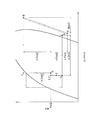
- FIG. 3 is a pressure-enthalpy diagram illustrating a refrigeration cycle during cooling operation.
- FIG. 6 is a pressure-enthalpy diagram illustrating a refrigeration cycle in a case where only the refrigerant charge amount is reduced.
- FIG. 6 is a pressure-enthalpy diagram illustrating a refrigeration cycle in a case where the refrigerant charge amount is reduced and the pressure is reduced until the gas-liquid two-phase state is obtained by the outdoor expansion valve.
- FIG. 10 is a pressure-enthalpy diagram illustrating a refrigeration cycle during cooling operation according to Modification D.
- FIG. 1 is a schematic configuration diagram of an air conditioner 1 according to an embodiment of the present invention.
- the air conditioner 1 is a device that cools a room such as a building by a vapor compression refrigeration cycle.
- the air conditioner 1 mainly includes an outdoor unit 2, a plurality of (here, two) indoor units 5a and 5b connected in parallel to each other, and a liquid that connects the outdoor unit 2 and the indoor units 5a and 5b.
- the refrigerant communication pipe 6 and the gas refrigerant communication pipe 7 are provided.
- the vapor compression refrigerant circuit 10 of the air conditioner 1 is configured by connecting the outdoor unit 2 and a plurality of indoor units 5a and 5b via a liquid refrigerant communication tube 6 and a gas refrigerant communication tube 7. ing.
- the indoor units 5a and 5b are installed in a room such as a building.
- the indoor units 5a and 5b are connected to the outdoor unit 2 via the liquid refrigerant communication tube 6 and the gas refrigerant communication tube 7 as described above, and constitute a part of the refrigerant circuit 10.
- the configuration of the indoor unit 5b is a subscript “Subscript “b” is attached instead of “a”, and description of each part is omitted.
- the indoor unit 5a mainly includes an indoor expansion valve 51a and an indoor heat exchanger 52a.
- the indoor unit 5a includes an indoor liquid refrigerant pipe 53a that connects the liquid side end of the indoor heat exchanger 52a and the liquid refrigerant communication pipe 6, and a gas side end of the indoor heat exchanger 52a and the gas refrigerant communication pipe 7. And an indoor gas refrigerant pipe 54a to be connected.
- the indoor expansion valve 51a is an electric expansion valve that adjusts the flow rate of the refrigerant flowing through the indoor heat exchanger 52a while reducing the refrigerant to a low pressure in the refrigeration cycle, and is provided in the indoor liquid refrigerant pipe 53a.
- the indoor heat exchanger 52a is a heat exchanger that functions as a low-pressure refrigerant evaporator in the refrigeration cycle to cool indoor air.
- the indoor unit 5a has an indoor fan 55a for sucking indoor air into the indoor unit 5a, exchanging heat with the refrigerant in the indoor heat exchanger 52a, and supplying the indoor air as supply air.
- the indoor unit 5a has an indoor fan 55a as a fan for supplying indoor air to the indoor heat exchanger 52a as a cooling source for the refrigerant flowing through the indoor heat exchanger 52a.
- the indoor fan 55a a centrifugal fan or a multi-blade fan driven by an indoor fan motor 56a is used as the indoor fan 55a.
- the rotation speed of the indoor fan motor 56a can be controlled by an inverter or the like, whereby the air volume of the indoor fan 55a can be controlled.
- the indoor unit 5a includes an indoor heat exchange liquid side sensor 57a that detects a refrigerant temperature Trl at the liquid side end of the indoor heat exchanger 52a, and a refrigerant temperature at the gas side end of the indoor heat exchanger 52a.
- An indoor heat exchange gas side sensor 58a for detecting Trg and an indoor air sensor 59a for detecting the temperature Tra of the indoor air sucked into the indoor unit 5a are provided.
- the indoor unit 5a has an indoor side control unit 5a that controls the operation of each unit constituting the indoor unit 5a.
- the indoor side control part 57a has the microcomputer, memory, etc. which were provided in order to control the indoor unit 5a, and is with the remote control (not shown) for operating the indoor unit 5a separately. Control signals and the like can be exchanged between them, and control signals and the like can be exchanged with the outdoor unit 2 via a communication line.
- the outdoor unit 2 is installed outside a building or the like. As described above, the outdoor unit 2 is connected to the indoor units 5a and 5b via the liquid refrigerant communication pipe 6 and the gas refrigerant communication pipe 7, and constitutes a part of the refrigerant circuit 10.
- the outdoor unit 2 mainly has a compressor 21 and an outdoor heat exchanger 24.
- the outdoor unit 2 includes an outdoor liquid refrigerant tube 25 that connects the liquid side end of the outdoor heat exchanger 24 and the liquid refrigerant communication tube 6, and an outdoor device that connects the suction side of the compressor 21 and the gas refrigerant communication tube 7. And a gas refrigerant pipe 26.
- a liquid side shut-off valve 27 is provided at a connection portion between the outdoor liquid refrigerant tube 25 and the liquid refrigerant communication tube 6, and a gas side closure is provided at a connection portion between the outdoor gas refrigerant tube 26 and the gas refrigerant communication tube 7.
- a valve 28 is provided. The liquid side closing valve 27 and the gas side closing valve 28 are manually opened and closed valves.
- the compressor 21 is a device that compresses the low-pressure refrigerant in the refrigeration cycle until it reaches a high pressure.
- a compressor having a hermetic structure in which a rotary type or scroll type positive displacement compression element (not shown) is rotationally driven by a compressor motor 22 is used as the compressor 21 .
- the compressor motor 22 can be controlled in rotational speed by an inverter or the like, and thereby the capacity of the compressor 21 can be controlled.
- the outdoor heat exchanger 24 is a heat exchanger that functions as a high-pressure refrigerant radiator in the refrigeration cycle.
- the outdoor unit 2 has an outdoor fan 29 for sucking outdoor air into the outdoor unit 2, exchanging heat with the refrigerant in the outdoor heat exchanger 24, and then discharging the air to the outside. That is, the outdoor unit 2 has an outdoor fan 29 as a fan that supplies outdoor air as a cooling source of the refrigerant flowing through the outdoor heat exchanger 24 to the outdoor heat exchanger 24.
- the outdoor fan 29 a propeller fan or the like driven by the outdoor fan motor 30 is used.
- the motor 30 for outdoor fans can control rotation speed by an inverter etc., and, thereby, air volume control of the outdoor fan 29 is attained.
- coolant with which the refrigerant circuit 10 was filled is the compressor 21, the outdoor heat exchanger 24, the liquid refrigerant communication pipe 6, the indoor expansion valves 51a and 51b, the indoor heat exchangers 52a and 52b, the gas refrigerant communication pipe 7, and the compression. It circulates in order of the machine 21.
- a refrigerant return pipe 31 is connected to the outdoor liquid refrigerant pipe 25, and a refrigerant cooler 35 and an outdoor expansion valve 36 are provided.
- the refrigerant return pipe 31 is a refrigerant pipe that branches a part of the refrigerant flowing through the outdoor liquid refrigerant pipe 25 and returns it to the compressor 21.
- the refrigerant cooler 35 is a heat exchanger that cools the refrigerant flowing through the outdoor liquid refrigerant pipe 25 with the refrigerant flowing through the refrigerant return pipe 31.
- the outdoor expansion valve 36 is an electric expansion valve provided in a portion of the outdoor liquid refrigerant pipe 25 that is closer to the outdoor heat exchanger 24 than the refrigerant cooler 35.
- the liquid refrigerant is communicated with a portion of the outdoor liquid refrigerant tube 25 that is closer to the liquid refrigerant communication tube 6 than the refrigerant cooler 35 (here, a portion between the refrigerant cooler 35 and the liquid side shut-off valve 27).
- a fluid pressure adjusting expansion valve 37 for reducing the pressure of the refrigerant is provided so that the refrigerant flowing through the pipe 6 is in a gas-liquid two-phase state and the refrigerant flowing through the outlet of the refrigerant cooler 35 is in a liquid state.
- the hydraulic pressure adjusting expansion valve 37 is an electric expansion valve.
- the refrigerant return pipe 31 is a refrigerant pipe that sends the refrigerant branched from the outdoor liquid refrigerant pipe 25 to the suction side of the compressor 21.
- the refrigerant return pipe 31 mainly has a refrigerant return inlet pipe 32 and a refrigerant return outlet pipe 33.
- the refrigerant return inlet pipe 32 is a part of the refrigerant flowing through the outdoor liquid refrigerant pipe 25 that is a part between the liquid side end of the outdoor heat exchanger 24 and the hydraulic pressure adjusting expansion valve 37 (here, the outdoor expansion valve 36 and the refrigerant).
- the refrigerant pipe is branched from a portion between the refrigerant cooler 35 and sent to the inlet of the refrigerant cooler 35 on the refrigerant return pipe 31 side.
- the refrigerant return inlet pipe 32 is provided with a refrigerant return expansion valve 34 that adjusts the flow rate of the refrigerant flowing through the refrigerant cooler 35 while reducing the refrigerant flowing through the refrigerant return pipe 31 to a low pressure in the refrigeration cycle.
- the refrigerant return expansion valve 34 is an electric expansion valve.
- the refrigerant return outlet pipe 33 is a refrigerant pipe that is sent from the outlet of the refrigerant cooler 35 on the refrigerant return pipe 31 side to the outdoor gas refrigerant pipe 26 connected to the suction side of the compressor 21.
- the refrigerant cooler 35 cools the refrigerant flowing through the outdoor liquid refrigerant pipe 25 by the low-pressure refrigerant in the refrigeration cycle flowing through the refrigerant return pipe 31.
- the outdoor unit 2 is provided with various sensors. Specifically, around the compressor 21 of the outdoor unit 2, a suction pressure sensor 38 for detecting the suction pressure Ps of the compressor 21, a suction temperature sensor 39 for detecting the suction temperature Ts of the compressor 21, and a compressor A discharge pressure sensor 40 for detecting the discharge pressure Pd of 21 and a discharge temperature sensor 41 for detecting the discharge temperature Td of the compressor 21 are provided. Further, in the outdoor liquid refrigerant pipe 25, the outdoor heat exchanger 24 is disposed in a portion closer to the outdoor heat exchanger 24 than the refrigerant cooler 35 (here, a portion closer to the outdoor heat exchanger 24 than the outdoor expansion valve 36).
- An outdoor heat exchange liquid side sensor 42 that detects the temperature Tol of the refrigerant at the liquid side end is provided.
- an outdoor air sensor 43 that detects the temperature Toa of the outdoor air sucked into the outdoor unit 2 is provided around the outdoor heat exchanger 24 or the outdoor fan 29.
- a refrigerant cooling side sensor 44 that detects the pressure Pol of the refrigerant in the portion of the outdoor liquid refrigerant pipe 25 where the refrigerant cooler 35 is provided is provided.
- the refrigerant return outlet pipe 33 is provided with a refrigerant return side sensor 45 that detects the temperature Tor of the refrigerant flowing through the outlet of the refrigerant cooler 35 on the refrigerant return pipe 31 side.
- the outdoor unit 2 includes an outdoor control unit 20 that controls the operation of each unit constituting the outdoor unit 2.
- the outdoor side control part 20 has a microcomputer, memory, etc. provided in order to control the outdoor unit 2, and communicates with the indoor side control parts 50a and 50b of the indoor units 5a and 5b. Control signals and the like can be exchanged via a line. That is, the indoor side control parts 50a and 50b and the outdoor side control part 20 are connected via the communication line, and the control part 8 which performs the operation control of the air conditioning apparatus 1 whole is comprised.
- the control unit 8 is connected so as to receive detection signals from various sensors 38 to 45, 57a to 59a, 57b to 59b, and based on these detection signals and the like.
- the various devices 21, 29, 34, 36, 37, 51a, 55a, 51b, and 55b are connected so as to be controlled.
- FIG. 2 is a control block diagram of the air conditioner 1.
- FIG. 3 is a pressure-enthalpy diagram illustrating the refrigeration cycle during the cooling operation.
- FIG. 4 is a pressure-enthalpy diagram illustrating the refrigeration cycle when only reducing the refrigerant charge amount.
- FIG. 5 is a pressure-enthalpy diagram illustrating the refrigeration cycle when the refrigerant filling amount is reduced and the outdoor expansion valve 36 is depressurized until it reaches a gas-liquid two-phase state.
- the refrigerant filled in the refrigerant circuit 10 is mainly composed of the compressor 21, the outdoor heat exchanger 24, the liquid refrigerant communication pipe 6, the indoor expansion valves 51a and 51b, the indoor heat exchangers 52a and 52b, and the gas.
- a cooling operation in which the refrigerant communication tube 7 and the compressor 21 are circulated in this order is performed.
- the refrigerant provided in the outdoor liquid refrigerant pipe 25 and the refrigerant return pipe 31 connected to the outdoor liquid refrigerant pipe 25 connecting the liquid side end of the outdoor heat exchanger 24 and the liquid refrigerant communication pipe 6 are provided.
- the operation of cooling the refrigerant flowing through the outdoor liquid refrigerant pipe 25 is also performed by the cooler 35. Further, in the cooling operation, the refrigerant flowing through the liquid refrigerant communication pipe is gas-liquid by the liquid pressure adjusting expansion valve 37 provided in the part of the outdoor liquid refrigerant pipe 25 closer to the liquid refrigerant communication pipe 6 than the refrigerant cooler 35.
- the operation of depressurizing the refrigerant is also performed so that the refrigerant flowing through the outlet of the refrigerant cooler 35 is in a liquid state so as to be in a two-phase state.
- movement of the air conditioning apparatus 1 demonstrated below is performed by the control part 8 which controls the component apparatus of the air conditioning apparatus 1.
- the refrigerant filled in the refrigerant circuit 10 is first sucked into the compressor 21 and compressed after being compressed from low pressure to high pressure in the refrigeration cycle (see points A and B in FIGS. 1 and 3).
- the gaseous refrigerant discharged from the compressor 21 flows into the gas side end of the outdoor heat exchanger 24.
- the refrigerant flowing into the gas side end of the outdoor heat exchanger 24 exchanges heat with the outdoor air supplied by the outdoor fan 29 in the outdoor heat exchanger 24 to dissipate heat to become a liquid refrigerant, thereby exchanging the outdoor heat. It flows out from the liquid side end of the vessel 24 (see point C in FIGS. 1 and 3).
- the control unit 8 controls the opening MVoo of the outdoor expansion valve 36 so that the supercooling degree SCo of the refrigerant at the liquid side end of the outdoor heat exchanger 24 becomes the target supercooling degree Scot.
- the control unit 8 obtains the refrigerant subcooling degree SCo at the liquid side end of the outdoor heat exchanger 24 from the refrigerant temperature Tol detected by the outdoor heat exchange liquid side sensor 42. More specifically, the control unit 8 subtracts the refrigerant temperature Toc from the refrigerant temperature Toc obtained by converting the discharge pressure Pd detected by the discharge pressure sensor 40 into a saturation temperature, thereby obtaining the refrigerant subcooling degree SCo. obtain.
- the target degree of supercooling SCot is as much as possible so that the refrigerant (see point D in FIGS. 1 and 3) flowing through the outdoor liquid refrigerant pipe 25 after being depressurized by the outdoor expansion valve 36 is easily maintained in a wet state.
- a small value (for example, 1 to 3 ° C.) is set. Then, the control unit 8 performs control to increase the opening MVoo of the outdoor expansion valve 36 when the supercooling degree SCo is larger than the target supercooling degree Scot, and the supercooling degree SCo is larger than the target supercooling degree Scot. When it is small, control is performed to reduce the opening degree MVoo of the outdoor expansion valve 36.
- the refrigerant that has flowed into the inlet of the refrigerant cooler 35 on the outdoor liquid refrigerant tube 25 side is further cooled in the refrigerant cooler 35 by exchanging heat with the refrigerant flowing through the refrigerant return tube 31 (ie, in a liquid state). (Refer to point E in FIGS. 1 and 3). At this time, a part of the refrigerant decompressed by the outdoor expansion valve 36 is branched to the refrigerant return pipe 31 and decompressed by the refrigerant return expansion valve 34 to near the low pressure of the refrigeration cycle.
- the refrigerant flowing into the inlet of the refrigerant cooler 35 on the refrigerant return pipe 31 side is heated in the refrigerant cooler 35 by exchanging heat with the refrigerant flowing in the outdoor liquid refrigerant pipe 35 to become a gaseous refrigerant.
- the refrigerant cooled in the refrigerant cooler 35 flows out from the outlet of the refrigerant cooler 35 on the outdoor liquid refrigerant tube 25 side, and is sent to the hydraulic pressure adjusting expansion valve 37.
- the control unit 8 controls the opening degree MVor of the refrigerant return expansion valve 34 so that the superheat degree SHo of the refrigerant at the outlet of the refrigerant cooler 35 on the refrigerant return pipe 31 side becomes the target superheat degree Shot. .
- the control unit 8 saturates the suction pressure Ps detected by the suction pressure sensor 38 from the refrigerant temperature Tor detected by the refrigerant return side sensor 45, and the superheat degree SHo of the refrigerant at the refrigerant return pipe 31 side outlet of the refrigerant cooler 35. It is obtained by subtracting the refrigerant temperature Tos obtained in terms of temperature.
- the target superheat degree Shot is set to a value of about 3 to 10 ° C. so that the refrigerant (see point A in FIGS. 1 and 3) sucked into the compressor 21 does not become highly wet.
- control part 8 performs control which enlarges the opening degree MVor of the refrigerant
- the refrigerant sent to the hydraulic pressure adjusting expansion valve 37 flows through the outlet of the refrigerant cooler 35 so that the refrigerant flowing through the liquid refrigerant communication tube 6 is in a gas-liquid two-phase state by the hydraulic pressure adjusting expansion valve 37.
- the refrigerant is decompressed so as to be in a liquid state (see points E and F in FIGS. 1 and 3).
- the control unit 8 controls the opening degree MVop of the hydraulic pressure adjusting expansion valve 37 so that the refrigerant pressure Pol at the portion where the refrigerant cooler 35 is provided in the outdoor liquid refrigerant pipe 25 becomes the target hydraulic pressure Polt. is doing.
- the control unit 8 obtains the refrigerant pressure Pol in the portion where the refrigerant cooler 35 is provided in the outdoor liquid refrigerant pipe 25 from the refrigerant pressure detected by the refrigerant cooling side sensor 44.
- the target hydraulic pressure Polt is set as high as possible so that the refrigerant flowing through the outlet of the refrigerant cooler 35 is in a liquid state.
- the control unit 8 performs control to increase the opening MVop of the hydraulic pressure adjusting expansion valve 37 when the refrigerant pressure Pol is higher than the target hydraulic pressure Polt, and the refrigerant pressure Pol is higher than the target hydraulic pressure Polt. When it is low, control is performed to reduce the opening MVop of the hydraulic pressure adjusting expansion valve 37.
- the refrigerant depressurized by the liquid pressure adjusting expansion valve 37 is sent to the liquid refrigerant communication pipe 6 through the liquid side closing valve 27.
- the refrigerant flowing through the liquid refrigerant communication tube 6 is in a gas-liquid two-phase state, the refrigerant flowing through the liquid refrigerant communication tube 6 is in a liquid state (that is, when the configuration of Patent Document 3 is adopted).
- the refrigerant communication pipe 6 is not filled with the liquid refrigerant, and the amount of refrigerant existing in the liquid refrigerant communication pipe 6 can be reduced accordingly.
- the refrigerant sent to the indoor units 5a and 5b is depressurized to near the low pressure of the refrigeration cycle by the indoor expansion valves 51a and 51b (see point H in FIGS. 1 and 3).
- the refrigerant after being decompressed by the indoor expansion valves 51a and 51b flows into the liquid side ends of the indoor heat exchangers 52a and 52b.
- the refrigerant that has flowed into the liquid side ends of the indoor heat exchangers 52a and 52b undergoes heat exchange with the indoor air supplied by the indoor fans 55a and 55b in the indoor heat exchangers 52a and 52b, and evaporates to form a gaseous refrigerant.
- the control unit 8 controls the opening MVrr of the indoor expansion valves 51a and 51b so that the superheat degree SHr of the refrigerant at the gas side ends of the indoor heat exchangers 52a and 52b becomes the target superheat degree SHrt. .
- the controller 8 determines the superheat degree SHr of the refrigerant at the gas side ends of the indoor heat exchangers 52a and 52b from the refrigerant temperature Trg detected by the indoor heat exchange gas side sensors 58a and 58b, and the indoor heat exchange liquid side sensors 57a and 57b. Is obtained by subtracting the detected refrigerant temperature Trl.
- the target superheat degree SHrt is set to a value of about 3 to 10 ° C. so that the refrigerant (see point A in FIGS. 1 and 3) sucked into the compressor 21 does not become highly wet.
- control part 8 performs control which enlarges the opening degree MVrr of the indoor expansion valves 51a and 51b when the superheat degree SHr is larger than the target superheat degree SHrt, and when the superheat degree SHr is smaller than the target superheat degree SHrt. In addition, control is performed to reduce the opening MVrr of the indoor expansion valves 51a and 51b.
- the refrigerant that has flowed out from the gas side ends of the indoor heat exchangers 52 a and 52 b is sent to the gas refrigerant communication tube 7. Then, the refrigerant sent to the gas refrigerant communication pipe 7 is sent to the outdoor unit 2 after being depressurized by pressure loss corresponding to the pipe length and pipe diameter, and through the gas side shut-off valve 28 and the outdoor gas refrigerant pipe 26. The refrigerant from the refrigerant return pipe 31 is again sucked into the compressor 21 (see point A in FIGS. 1 and 3).
- the outdoor unit 2 having the compressor 21 and the outdoor heat exchanger 24, and the plurality of indoor units 5a and 5b having the indoor expansion valves 51a and 51b and the indoor heat exchangers 52a and 52b
- the refrigerant circuit 10 configured by connecting through the liquid refrigerant communication tube 6 and the gas refrigerant communication tube 7, first, an outdoor unit connecting the liquid side end of the outdoor heat exchanger 24 and the liquid refrigerant communication tube 6.
- the liquid refrigerant pipe 25 is provided with a refrigerant return pipe 31 and a refrigerant cooler 35.
- the refrigerant return pipe 31 is a refrigerant pipe that sends the refrigerant branched from the outdoor liquid refrigerant pipe 25 to the suction side of the compressor 21, the pressure of the refrigerant flowing through the outdoor liquid refrigerant pipe 25 and the low pressure of the refrigeration cycle are reduced.
- the cooling function in the refrigerant cooler 35 can be obtained by utilizing the pressure difference.
- the liquid pressure adjusting expansion valve 37 in the portion of the outdoor liquid refrigerant pipe 25 closer to the liquid refrigerant communication pipe 6 than the refrigerant cooler 35, the liquid refrigerant communication pipe 6 flows. Outdoors so that the refrigerant is in a gas-liquid two-phase state (see points F and G in FIG.
- the pressure of the refrigerant flowing through the refrigerant cooler 35 is unlikely to decrease, and a refrigerant with high wetness can be caused to flow through the refrigerant cooler 35.
- the refrigerant flowing through the outdoor liquid refrigerant pipe 25 and the refrigerant return Since it becomes easy to ensure a pressure difference (see ⁇ Pad in FIG. 3) with the refrigerant flowing through the pipe 31, the cooling function (see ⁇ Qde in FIG. 3) in the refrigerant cooler 35 can be sufficiently exhibited. Then, the flow rate of the refrigerant sent to the plurality of indoor units 5a and 5b can be reduced, and the pressure loss (see ⁇ Pai in FIG. 3) in the gas refrigerant communication tube 7 and the like can be reduced. 3) and operational efficiency (value obtained by dividing ⁇ Qhi by Wab in FIG. 3) can be improved.
- the outdoor unit 2 having the compressor 21 and the outdoor heat exchanger 24 and the plurality of indoor units 5a and 5b having the indoor expansion valves 51a and 51b and the indoor heat exchangers 52a and 52b are liquidated.
- control unit 8 sets the refrigerant pressure Pol in the portion of the outdoor liquid refrigerant pipe 25 where the refrigerant cooler 35 is provided.
- the opening degree MVop of the hydraulic pressure adjusting expansion valve 37 is controlled so as to be the target hydraulic pressure Polt.
- the pressure Pol of the refrigerant flowing through the refrigerant cooler 35 can be maintained high, and thereby, a refrigerant with high wetness can be reliably passed through the refrigerant cooler 35.
- the outdoor liquid refrigerant pipe 25 is provided in a portion on the outdoor heat exchanger 24 side of the refrigerant cooler 35 (here, a portion between the outdoor expansion valve 36 and the hydraulic pressure adjusting expansion valve 37). Since the refrigerant pressure Pol in the portion of the outdoor liquid refrigerant pipe 25 in which the refrigerant cooler 35 is provided can be accurately obtained using the refrigerant cooling side sensor 44, the control of the hydraulic pressure adjusting expansion valve 37 is accurate. Can be done well.
- an outdoor expansion valve 36 is provided in a portion of the outdoor liquid refrigerant pipe 25 that is closer to the outdoor heat exchanger 24 than the refrigerant cooler 35, and the degree of refrigerant supercooling at the liquid side end of the outdoor heat exchanger 24 is provided.
- the degree of opening MVoo of the outdoor expansion valve 36 is controlled so that SCo (see point C in FIG. 3) becomes the target supercooling degree SCot. For this reason, the pressure Pol of the refrigerant in the portion where the refrigerant cooler 35 is provided in the outdoor liquid refrigerant pipe 25 tends to decrease (see ⁇ Pcd in FIG. 3).
- the hydraulic pressure adjusting expansion valve 37 is configured such that the refrigerant pressure Pol at the portion of the outdoor liquid refrigerant pipe 25 where the refrigerant cooler 35 is provided becomes the target hydraulic pressure Polt.
- the opening degree MVop is controlled.
- the refrigerant flowing in the outdoor liquid refrigerant pipe 25 in the portion closer to the outdoor heat exchanger 24 than the refrigerant cooler 35 flows through the refrigerant cooler 35 even though the refrigerant is decompressed by the outdoor expansion valve 37.
- the refrigerant pressure Pol can be maintained high, and a refrigerant with high wetness can be reliably passed through the refrigerant cooler 35.
- the liquid side end of the outdoor heat exchanger 24 is used by using the outdoor heat exchanger side sensor 42 provided in the outdoor liquid refrigerant pipe 25 in the portion closer to the outdoor heat exchanger 24 than the outdoor expansion valve 37. Since the supercooling degree SCo of the refrigerant in can be accurately obtained, the outdoor expansion valve 36 can also be controlled with high accuracy.
- the liquid pressure adjusting expansion valve 37 is provided in a portion of the outdoor liquid refrigerant pipe 25 closer to the liquid refrigerant communication pipe 6 than the refrigerant cooler 35. It is assumed that the refrigerant charge amount is reduced. That is, the case where only the reduction of the refrigerant filling amount is performed in the same configuration as that of Patent Document 3 is assumed. Then, as shown in FIG. 4, unlike the refrigeration cycle shown by the two-dot chain line (that is, the refrigeration cycle of FIG. 3), the liquid side of the outdoor heat exchanger 24 is caused by the small refrigerant filling amount.
- an outdoor expansion valve connected to the liquid side end of the outdoor heat exchanger 24
- the refrigerant is greatly decompressed by 36. That is, in the same configuration as that of Patent Document 3, as in Patent Documents 1 and 2, the refrigerant flowing through the liquid refrigerant communication tube 6 is connected to the liquid side end of the outdoor heat exchanger 24 so that the gas-liquid two-phase state is obtained. It is conceivable that the refrigerant is decompressed by the outdoor expansion valve 36. However, in this case, as shown in FIG.
- the outdoor connected to the liquid side end of the outdoor heat exchanger 24. Due to the significant pressure reduction of the refrigerant by the expansion valve 36 (see ⁇ Pcd2 in FIG. 5), the pressure Pol2 of the refrigerant flowing through the refrigerant cooler 35 is reduced (Pol2 ⁇ Pol), and the refrigerant cooler 35 is supplied with a highly humid refrigerant. It becomes impossible to flow (see points D, E, and F in FIG. 5). In addition, it becomes difficult to secure a pressure difference (see ⁇ Pad2 in FIG.
- the liquid pressure adjusting expansion valve 37 is provided in a portion of the outdoor liquid refrigerant pipe 25 closer to the liquid refrigerant communication pipe 6 than the refrigerant cooler 35 ( Unlike the case shown in FIG. 3, the amount of refrigerant charged in the refrigerant circuit 10 cannot be reduced while improving the refrigerating capacity and the operation efficiency by the refrigerant return pipe 31 and the refrigerant cooler 35.
- the refrigerant flowing through the liquid refrigerant communication tube 6 is in a gas-liquid two-phase state
- the refrigerant flowing through the outlet of the refrigerant cooler 35 is in a liquid state.
- the opening degree MVoo of the outdoor expansion valve 36 is controlled so that the supercooling degree SCo of the refrigerant at the liquid side end of the outdoor heat exchanger 24 becomes the target supercooling degree Scot
- the refrigerant cooler in the outdoor liquid refrigerant pipe 25 is controlled.
- the degree of opening MVop of the hydraulic pressure adjusting expansion valve 37 is controlled so that the refrigerant pressure Pol at the portion where 35 is provided becomes the target hydraulic pressure Polt.
- the control of these two expansion valves 36 and 37 tends to influence each other, and the opening MVoo and MVop of both expansion valves 36 and 37 tend to be difficult to stabilize.
- the outdoor expansion valve 36 and the hydraulic pressure adjustment expansion valve 37 are stable at a certain opening (that is, a state where the outdoor expansion valve 36 and the target hydraulic pressure Polt are stable)
- the outdoor expansion valve 36 When the opening degree MVoo is controlled to increase, the refrigerant on the downstream side of the outdoor expansion valve 36 (that is, the portion of the outdoor liquid refrigerant pipe 25 between the outdoor expansion valve 36 and the hydraulic pressure adjusting expansion valve 37) is controlled.
- the pressure Pol changes in the direction of increasing.
- the opening range that can be changed in the control of the hydraulic pressure adjusting expansion valve 37 is limited to the lower limit opening MVopm or more, and the lower limit opening MVopm is corrected according to the opening MVoo of the outdoor expansion valve 36.
- the outdoor expansion valve 36 is controlled downstream by the opening degree control of the outdoor expansion valve 36 (that is, the outdoor expansion valve 36 and the hydraulic pressure adjusting expansion valve 37 in the outdoor liquid refrigerant pipe 25). It is possible to quickly follow the change in pressure of the refrigerant in the part between the two.
- a function is set such that the lower limit opening MVopm of the hydraulic pressure adjusting expansion valve 37 becomes larger as the opening degree MVoo of the outdoor expansion valve 36 becomes larger.
- the lower limit opening MVopm can be corrected according to this function.
- the refrigerant cooling side sensor 44 provided in a portion of the outdoor liquid refrigerant pipe 25 between the outdoor expansion valve 36 and the hydraulic pressure adjusting expansion valve 37 detects The refrigerant pressure Pol at the portion of the outdoor liquid refrigerant pipe 25 where the refrigerant cooler 35 is provided is obtained from the pressure value of the refrigerant to be controlled, and the opening degree of the hydraulic pressure adjusting expansion valve 37 is controlled.
- the pressure Pol of the refrigerant may be obtained not from the refrigerant pressure detected by the refrigerant cooling side sensor 44 including a pressure sensor but from a state quantity equivalent to the pressure of the refrigerant.
- the refrigerant at the liquid side end of the outdoor heat exchanger 24 including the downstream side of the outdoor expansion valve 36 is close to a saturated liquid state (see points C and D in FIG. 3), as shown in FIG.
- a refrigerant cooling side sensor 44 including a temperature sensor is provided in a portion of the liquid refrigerant pipe 25 closer to the outdoor heat exchanger 24 than the liquid pressure adjusting expansion valve 37, and the temperature value of the refrigerant detected by the refrigerant cooling side sensor 44 is determined. You may make it obtain the refrigerant
- the control for realizing that the refrigerant flowing through the liquid refrigerant communication tube 6 is in a gas-liquid two-phase state and the refrigerant flowing through the outlet of the refrigerant cooler 35 is in a liquid state is limited to this.
- the outdoor expansion valve that controls the opening degree so that the supercooling degree SCo of the refrigerant at the liquid side end of the outdoor heat exchanger 24 becomes the target supercooling degree Scot. 36 may be fully opened, and the control unit 8 may control the opening MVop of the hydraulic pressure adjusting expansion valve 37 so that the supercooling degree SCo of the refrigerant becomes the target supercooling degree SCot.
- the outdoor expansion valve 36 is fully opened here, the present invention is not limited to this, and the outdoor expansion valve 36 may not be provided.
- the outdoor heat exchanger in the outdoor liquid refrigerant pipe 25 is more than the hydraulic pressure adjusting expansion valve 37. It becomes easy to maintain the refrigerant flowing through the portion on the 24 side in a liquid state. For this reason, similarly to the above-described embodiment and Modifications A and B, the pressure of the refrigerant flowing through the refrigerant cooler 35 is unlikely to decrease, and a highly humid refrigerant can be caused to flow through the refrigerant cooler 35.
- the cooling function (see ⁇ Qde in FIG. 3) in the refrigerant cooler 35 is sufficient. Will be able to demonstrate. Then, the flow rate of the refrigerant sent to the plurality of indoor units 5a and 5b can be reduced, and the pressure loss (see ⁇ Pai in FIG. 3) in the gas refrigerant communication tube 7 and the like can be reduced. 3) and operational efficiency (value obtained by dividing ⁇ Qhi by Wab in FIG. 3) can be improved.
- the outdoor unit 2 having the compressor 21 and the outdoor heat exchanger 24, and the plurality of indoor units 5a having the indoor expansion valves 51a and 51b and the indoor heat exchangers 52a and 52b.
- the air conditioner 1 including the refrigerant circuit 10 configured by connecting the liquid refrigerant communication pipe 6 and the gas refrigerant communication pipe 7 to each other, the refrigerating capacity and operation by the refrigerant return pipe 31 and the refrigerant cooler 35
- the amount of refrigerant charged in the refrigerant circuit 10 can be reduced while improving the efficiency.
- the refrigerant return pipe 31 is used as a refrigerant pipe that sends the refrigerant branched from the outdoor liquid refrigerant pipe 25 to the suction side of the compressor 21, and the pressure of the refrigerant flowing in the outdoor liquid refrigerant pipe 25 and the refrigeration
- the cooling function in the refrigerant cooler 35 is obtained by utilizing the pressure difference from the low pressure of the cycle.
- the refrigerant return pipe 31 is not limited to this.
- the refrigerant branched from the outdoor liquid refrigerant pipe 25 in the refrigerant return pipe 31 is sent in the middle of the compression stroke of the compressor 21.
- a cooling function in the refrigerant cooler 35 may be obtained by using a pressure difference between the pressure of the refrigerant flowing through the outdoor liquid refrigerant pipe 25 and the intermediate pressure of the refrigeration cycle.
- the refrigerant return pipe 31 also functions as a refrigerant pipe that sends the refrigerant branched from the outdoor liquid refrigerant pipe 25 to the suction side of the compressor 21
- the refrigerant return outlet of the refrigerant return pipe 31 is used.
- the pipe 33 is branched into two, and one is connected via a check valve 46 in the middle of the compression stroke of the compressor 21 and the other is connected to the suction side of the compressor 21 via an electromagnetic valve 47. ing.
- a part of the refrigerant decompressed by the outdoor expansion valve 36 branched to the refrigerant return pipe 31 is intermediated in the refrigeration cycle by the refrigerant return expansion valve 34.
- the pressure is reduced to near the pressure.
- the refrigerant flowing through the refrigerant return pipe 31 after being decompressed by the refrigerant return expansion valve 34 flows into the inlet of the refrigerant cooler 35 on the refrigerant return pipe 31 side.
- the refrigerant flowing into the inlet of the refrigerant cooler 35 on the refrigerant return pipe 31 side is heated in the refrigerant cooler 35 by exchanging heat with the refrigerant flowing in the outdoor liquid refrigerant pipe 35 to become a gaseous refrigerant. It flows out from the outlet on the refrigerant return pipe 31 side of the vessel 35 and is returned in the middle of the compression stroke of the compressor 21.
- the liquid pressure adjusting expansion valve 37 in the portion of the outdoor liquid refrigerant pipe 25 closer to the liquid refrigerant communication pipe 6 than the refrigerant cooler 35, the liquid refrigerant communication is performed.
- the refrigerant flowing through the pipe 6 is in a gas-liquid two-phase state (see points F and G in FIG. 8), and the refrigerant flowing in the outlet of the refrigerant cooler 35 is in a liquid state (point E in FIG. 8).
- the refrigerant flowing through the outdoor liquid refrigerant pipe 25 is depressurized (see ⁇ Pef in FIG. 8).
- the pressure of the refrigerant flowing through the refrigerant cooler 35 is unlikely to decrease, and a refrigerant with high wetness can be caused to flow through the refrigerant cooler 35.
- the refrigerant flowing through the outdoor liquid refrigerant pipe 25 and the refrigerant return Since it becomes easy to ensure a pressure difference (see ⁇ Pdj in FIG. 8) with the refrigerant flowing through the pipe 31, the cooling function (see ⁇ Qde in FIG. 8) in the refrigerant cooler 35 can be sufficiently exhibited.
- the flow rate of the refrigerant returned through the refrigerant return pipe 31 in the middle of the compression stroke of the compressor 21 see point J in FIG.
- the outdoor unit 2 having the compressor 21 and the outdoor heat exchanger 24, and a plurality of indoor units 5a having the indoor expansion valves 51a and 51b and the indoor heat exchangers 52a and 52b
- the air-conditioning apparatus 1 including the refrigerant circuit 10 configured by connecting the liquid refrigerant communication pipe 6 and the gas refrigerant communication pipe 7 to each other, the refrigerating capacity and the operating efficiency of the refrigerant return pipe 31 and the refrigerant cooler 35 are provided.
- the amount of refrigerant charged in the refrigerant circuit 10 can be reduced.
- the present invention is applied by taking as an example the configuration having the refrigerant circuit 10 that performs the cooling operation.
- the present invention is not limited to this, and the outdoor unit 2 has four paths.
- the present invention can be applied to any configuration that performs at least the cooling operation, such as a configuration that includes a refrigerant circuit that is provided with a switching valve and is capable of switching between the cooling operation and the heating operation.
- the outdoor unit 2 an outdoor unit of an air heat source having an outdoor fan 29 for supplying outdoor air as a heat source for heat exchange with the refrigerant to the outdoor heat exchanger 24 is adopted.
- the present invention is not limited to this, and may be an outdoor unit of a water heat source that does not have the outdoor fan 29 and uses water as a heat source for heat exchange with the refrigerant in the outdoor heat exchanger 24. .
- the present invention connects an outdoor unit having a compressor and an outdoor heat exchanger to a plurality of indoor units having an indoor expansion valve and an indoor heat exchanger via a liquid refrigerant communication tube and a gas refrigerant communication tube.
- the refrigerant circuit is configured and the refrigerant filled in the refrigerant circuit circulates in the order of the compressor, the outdoor heat exchanger, the liquid refrigerant communication tube, the indoor expansion valve, the indoor heat exchanger, the gas refrigerant communication tube, and the compressor. Widely applicable to air conditioners.
- Air conditioning apparatus Outdoor unit 5a, 5b Indoor unit 6 Liquid refrigerant communication pipe 7 Gas refrigerant communication pipe 8 Control part 10 Refrigerant circuit 21 Compressor 24 Outdoor heat exchanger 25 Outdoor liquid refrigerant pipe 31 Refrigerant return pipe 35 Refrigerant cooler 36 Outdoor expansion valve 37 Fluid pressure adjusting expansion valve 42 Outdoor heat exchange side sensor 44 Refrigerant cooling side sensor 51a, 51b Indoor expansion valve 52a, 52b Indoor heat exchanger
Landscapes
- Engineering & Computer Science (AREA)
- Mechanical Engineering (AREA)
- General Engineering & Computer Science (AREA)
- Physics & Mathematics (AREA)
- Thermal Sciences (AREA)
- Chemical & Material Sciences (AREA)
- Combustion & Propulsion (AREA)
- Air Conditioning Control Device (AREA)
- Compression-Type Refrigeration Machines With Reversible Cycles (AREA)
Abstract
空気調和装置(1)は、室外液冷媒管(25)のうち冷媒冷却器(35)よりも液冷媒連絡管(6)側の部分に、液冷媒連絡管(6)を流れる冷媒が気液二相状態になるように、かつ、冷媒冷却器(35)の出口を流れる冷媒が液状態になるように、冷媒を減圧する液圧調整膨張弁(37)を設けている。
Description
本発明は、空気調和装置、特に、圧縮機及び室外熱交換器を有する室外ユニットと、室内膨張弁及び室内熱交換器を有する複数の室内ユニットとを、液冷媒連絡管及びガス冷媒連絡管を介して接続することによって構成した冷媒回路を含んでおり、冷媒回路に充填された冷媒が圧縮機、室外熱交換器、液冷媒連絡管、室内膨張弁、室内熱交換器、ガス冷媒連絡管、圧縮機の順に循環する空気調和装置に関する。
従来より、圧縮機及び室外熱交換器を有する室外ユニットと、室内熱交換器を有する室内ユニットとを、液冷媒連絡管及びガス冷媒連絡管を介して接続することによって構成した冷媒回路を含む空気調和装置がある。このような空気調和装置として、特許文献1、2(特開昭63-197853号公報、特開平5-332630号公報)に示すように、冷媒回路に充填された冷媒が圧縮機、室外熱交換器、液冷媒連絡管、室内熱交換器、ガス冷媒連絡管、圧縮機の順に循環する冷房運転時に、室外熱交換器の液側端に接続された室外膨張弁やキャピラリチューブによって冷媒を減圧した後に、液冷媒連絡管に送る構成を採用したものがある。そして、このような構成を採用することによって、液冷媒連絡管を流れる冷媒が気液二相状態になるようにし、冷媒回路に充填される冷媒量を削減することができるとされている。
また、従来より、圧縮機及び室外熱交換器を有する室外ユニットと、室内膨張弁及び室内熱交換器を有する複数の室内ユニットとを、液冷媒連絡管及びガス冷媒連絡管を介して接続することによって構成した冷媒回路を含む空気調和装置において、特許文献3(特開2010-236834号公報)に示すように、過冷却熱交換器(冷媒冷却器)及び過冷却用分岐配管(冷媒戻し管)を設けたものがある。ここで、冷媒戻し管は、室外熱交換器の液側端と液冷媒連絡管とを接続する室外液冷媒管に、室外液冷媒管を流れる冷媒の一部を分岐して圧縮機に戻すように接続されており、冷媒冷却器は、冷媒戻し管を流れる冷媒によって室外液冷媒管を流れる冷媒を冷却するようになっている。
ここで、上記後者の冷媒戻し管及び冷媒冷却器を有する冷媒回路を含む空気調和装置においては、冷房運転時に、室外ユニットから液状態の冷媒が液冷媒連絡管を介して室内ユニットに送られ、そして、室内ユニットに設けられた室内膨張弁によって冷媒を減圧することになる。このため、上記後者の構成では、冷媒回路に充填される冷媒量が、液冷媒連絡管が液状態の冷媒で満たされる分だけ多くなってしまう。
これに対して、上記後者の構成においても、冷媒回路に充填される冷媒量を削減するために、上記前者の室外熱交換器の液側端に接続された室外膨張弁やキャピラリチューブによって冷媒を減圧する構成を採用することが考えられる。
しかし、上記後者の構成に上記前者の構成を採用すると、室外熱交換器の液側端に接続された室外膨張弁やキャピラリチューブによる冷媒の減圧によって、冷媒冷却器を流れる冷媒の圧力が低下してしまい、冷媒冷却器に湿り度の高い冷媒を流すことができなくなる。また、室外液冷媒管を流れる冷媒と冷媒戻し管を流れる冷媒との圧力差も確保しにくくなる。そうすると、冷媒冷却器における冷却機能が十分に発揮できなくなってしまい、空気調和装置全体としての冷凍能力や運転効率の低下を招くことになる。
本発明の課題は、圧縮機及び室外熱交換器を有する室外ユニットと、室内膨張弁及び室内熱交換器を有する複数の室内ユニットとを、液冷媒連絡管及びガス冷媒連絡管を介して接続することによって構成した冷媒回路を含む空気調和装置において、冷媒戻し管及び冷媒冷却器による冷凍能力や運転効率の向上を図りつつ、冷媒回路に充填される冷媒量を削減できるようにすることにある。
第1の観点にかかる空気調和装置は、圧縮機及び室外熱交換器を有する室外ユニットと、室内膨張弁及び室内熱交換器を有する複数の室内ユニットとを、液冷媒連絡管及びガス冷媒連絡管を介して接続することによって構成した冷媒回路を含んでおり、冷媒回路に充填された冷媒が圧縮機、室外熱交換器、液冷媒連絡管、室内膨張弁、室内熱交換器、ガス冷媒連絡管、圧縮機の順に循環する空気調和装置である。そして、ここでは、室外熱交換器の液側端と液冷媒連絡管とを接続する室外液冷媒管に、室外液冷媒管を流れる冷媒の一部を分岐して圧縮機に戻す冷媒戻し管を接続するとともに、冷媒戻し管を流れる冷媒によって室外液冷媒管を流れる冷媒を冷却する冷媒冷却器を設けている。しかも、ここでは、室外液冷媒管のうち冷媒冷却器よりも液冷媒連絡管側の部分に、液冷媒連絡管を流れる冷媒が気液二相状態になるように、かつ、冷媒冷却器の出口を流れる冷媒が液状態になるように、冷媒を減圧する液圧調整膨張弁を設けている。
ここでは、上記のように、液冷媒連絡管を流れる冷媒が気液二相状態になるように冷媒を減圧するにあたり、室外熱交換器の液側端と液冷媒連絡管とを接続する室外液冷媒管のうち冷媒冷却器よりも液冷媒連絡管側の部分に液圧調整膨張弁を設けることで、液冷媒連絡管を流れる冷媒が気液二相状態になるように、かつ、冷媒冷却器の出口を流れる冷媒が液状態になるように、室外液冷媒管を流れる冷媒を減圧している。
このため、ここでは、冷媒冷却器を流れる冷媒の圧力が低下しにくくなり、冷媒冷却器に湿り度の高い冷媒を流すことができ、また、室外液冷媒管を流れる冷媒と冷媒戻し管を流れる冷媒との圧力差も確保しやすくなることから、冷媒冷却器における冷却機能が十分に発揮できるようになる。そうすると、複数の室内ユニットに送る冷媒の流量を低減することができ、そして、ガス冷媒連絡管等における圧力損失を低減することもできるため、冷凍能力や運転効率を向上させることができる。
このように、ここでは、圧縮機及び室外熱交換器を有する室外ユニットと、室内膨張弁及び室内熱交換器を有する複数の室内ユニットとを、液冷媒連絡管及びガス冷媒連絡管を介して接続することによって構成した冷媒回路を含む空気調和装置において、冷媒戻し管及び冷媒冷却器による冷凍能力や運転効率の向上を図りつつ、冷媒回路に充填される冷媒量を削減することができる。
第2の観点にかかる空気調和装置は、第1の観点にかかる空気調和装置において、室外ユニット及び/又は複数の室内ユニットが、液圧調整膨張弁を含む構成機器を制御する制御部を有している。そして、ここでは、制御部が、室外熱交換器の液側端における冷媒の過冷却度が目標過冷却度になるように液圧調整膨張弁の開度を制御することによって、液冷媒連絡管を流れる冷媒が気液二相状態になるように、かつ、冷媒冷却器の出口を流れる冷媒が液状態になるように、液圧調整膨張弁に冷媒を減圧させる。
ここでは、上記のように、室外熱交換器の液側端における冷媒の過冷却度が目標過冷却度になるように液圧調整膨張弁の開度を制御しているため、室外液冷媒管のうち液圧調整膨張弁よりも室外熱交換器側の部分を流れる冷媒を液状態に維持しやすくなり、これにより、冷媒冷却器に湿り度の高い冷媒を確実に流すことができる。
第3の観点にかかる空気調和装置は、第2の観点にかかる空気調和装置において、室外液冷媒管のうち冷媒冷却器よりも室外熱交換器側の部分に、冷媒の温度を検出する室外熱交液側センサを設けている。そして、ここでは、制御部が、室外熱交液側センサが検出した冷媒の温度から室外熱交換器の液側端における冷媒の過冷却度を得る。
ここでは、上記のように、室外液冷媒管のうち冷媒冷却器よりも室外熱交換器側の部分に設けられた室外熱交液側センサを用いて、室外熱交換器の液側端における冷媒の過冷却度を正確に得ることができるため、液圧調整膨張弁の制御を精度よく行うことができる。
第4の観点にかかる空気調和装置は、第1の観点にかかる空気調和装置において、室外ユニット及び/又は複数の室内ユニットが、液圧調整膨張弁を含む構成機器を制御する制御部を有している。そして、ここでは、制御部が、室外液冷媒管のうち冷媒冷却器が設けられた部分における冷媒の圧力が目標液圧になるように液圧調整膨張弁の開度を制御することによって、液冷媒連絡管を流れる冷媒が気液二相状態になるように、かつ、冷媒冷却器の出口を流れる冷媒が液状態になるように、液圧調整膨張弁に冷媒を減圧させる。
ここでは、上記のように、室外液冷媒管のうち冷媒冷却器が設けられた部分における冷媒の圧力が目標液圧になるように液圧調整膨張弁の開度を制御しているため、冷媒冷却器を流れる冷媒の圧力を高く維持することができ、これにより、冷媒冷却器に湿り度の高い冷媒を確実に流すことができる。
第5の観点にかかる空気調和装置は、第4の観点にかかる空気調和装置において、室外液冷媒管のうち液圧調整膨張弁よりも室外熱交換器側の部分に、冷媒の圧力又はこれに等価な状態量を検出する冷媒冷却側センサを設けている。そして、ここでは、制御部が、冷媒冷却側センサが検出した冷媒の圧力又はこれに等価な状態量から、室外液冷媒管のうち冷媒冷却器が設けられた部分における冷媒の圧力を得る。
ここでは、上記のように、室外液冷媒管のうち冷媒冷却器よりも室外熱交換器側の部分に設けられた冷媒冷却側センサを用いて、室外液冷媒管のうち冷媒冷却器が設けられた部分における冷媒の圧力を正確に得ることができるため、液圧調整膨張弁の制御を精度よく行うことができる。
第6の観点にかかる空気調和装置は、第4又は第5の観点にかかる空気調和装置において、室外液冷媒管のうち冷媒冷却器よりも室外熱交換器側の部分に、室外膨張弁を設けている。そして、ここでは、制御部が、室外熱交換器の液側端における冷媒の過冷却度が目標過冷却度になるように室外膨張弁の開度を制御するとともに、室外液冷媒管のうち冷媒冷却器が設けられた部分における冷媒の圧力が目標液圧になるように液圧調整膨張弁の開度を制御することによって、液冷媒連絡管を流れる冷媒が気液二相状態になるように、かつ、冷媒冷却器の出口を流れる冷媒が液状態になるように、液圧調整膨張弁に冷媒を減圧させる。
ここでは、上記のように、室外液冷媒管のうち冷媒冷却器よりも室外熱交換器側の部分に室外膨張弁を設けて、室外熱交換器の液側端における冷媒の過冷却度が目標過冷却度になるように室外膨張弁の開度を制御している。このため、室外液冷媒管のうち冷媒冷却器が設けられた部分における冷媒の圧力が低下する傾向にある。そこで、ここでは、上記のように、室外液冷媒管のうち冷媒冷却器が設けられた部分における冷媒の圧力が目標液圧になるように液圧調整膨張弁の開度を制御している。
これにより、ここでは、室外液冷媒管のうち冷媒冷却器よりも室外熱交換器側の部分を流れる冷媒が室外膨張弁によって減圧されるにもかかわらず、冷媒冷却器を流れる冷媒の圧力を高く維持することができ、冷媒冷却器に湿り度の高い冷媒を確実に流すことができる。
第7の観点にかかる空気調和装置は、第6の観点にかかる空気調和装置において、室外液冷媒管のうち室外膨張弁よりも室外熱交換器側の部分に、冷媒の温度を検出する室外熱交液側センサを設け、また、室外液冷媒管のうち室外膨張弁と液圧調整膨張弁との間の部分に、冷媒の圧力又はこれに等価な状態量を検出する冷媒冷却側センサを設けている。そして、ここでは、制御部が、室外熱交液側センサが検出した冷媒の温度から室外熱交換器の液側端における冷媒の過冷却度を得るとともに、冷媒冷却側センサが検出した冷媒の圧力又はこれに等価な状態量から室外液冷媒管のうち冷媒冷却器が設けられた部分における冷媒の圧力を得る。
ここでは、上記のように、室外液冷媒管のうち室外膨張弁よりも室外熱交換器側の部分に設けられた室外熱交液側センサを用いて、室外熱交換器の液側端における冷媒の過冷却度を正確に得ることができ、かつ、室外液冷媒管のうち室外膨張弁と液圧調整膨張弁との間の部分に設けられた冷媒冷却側センサを用いて、室外液冷媒管のうち冷媒冷却器が設けられた部分における冷媒の圧力を正確に得ることができるため、室外膨張弁及び液圧調整膨張弁の制御を精度よく行うことができる。
第8の観点にかかる空気調和装置は、第6又は第7の観点にかかる空気調和装置において、制御部が、室外液冷媒管のうち冷媒冷却器が設けられた部分における冷媒の圧力が目標液圧になるように液圧調整膨張弁の開度を制御する際に、液圧調整膨張弁を下限開度以上の開度範囲内で制御するとともに、下限開度を室外膨張弁の開度に応じて補正する。
ここでは、上記のように、室外熱交換器の液側端における冷媒の過冷却度が目標過冷却度になるように室外膨張弁の開度を制御するとともに室外液冷媒管のうち冷媒冷却器が設けられた部分における冷媒の圧力が目標液圧になるように液圧調整膨張弁の開度を制御すると、両膨張弁の制御が互いに影響しやすく、両膨張弁の開度が安定しにくい傾向がある。例えば、室外膨張弁及び液圧調整膨張弁がある開度で安定している状態(すなわち、目標過冷却度及び目標液圧で安定している状態)において、室外膨張弁の開度が大きくなる方向に制御されると、室外膨張弁の下流側(すなわち、室外液冷媒管のうち室外膨張弁と液圧調整膨張弁との間の部分)における冷媒の圧力が高くなる方向に変化することになる。そして、このような室外膨張弁の開度の変化による冷媒の圧力変化は、かなり急激なものであるため、液圧調整膨張弁の開度を素早く制御することが要求されるところ、制御感度を過度に上げると安定性が損なわれてしまい、結果的に、液圧調整膨張弁の開度、さらには、両膨張弁の開度が安定しにくくなる。そこで、ここでは、上記のように、液圧調整膨張弁の制御において変更可能な開度範囲を下限開度以上に制限するとともに、この下限開度を室外膨張弁の開度に応じて補正するようにして、制御感度を過度に上げることなく、室外膨張弁の開度制御による室外膨張弁の下流側(すなわち、室外液冷媒管のうち室外膨張弁と液圧調整膨張弁との間の部分)における冷媒の圧力変化に素早く追従できるようにしている。
これにより、ここでは、室外膨張弁の開度制御と液圧調整膨張弁の開度制御とが互いに影響しやすいにもかかわらず、両膨張弁の制御を、追従性よく、かつ、安定的に行うことができる。
第9の観点にかかる空気調和装置は、第1~第8の観点のいずれかにかかる空気調和装置において、冷媒戻し管が、室外液冷媒管から分岐した冷媒を圧縮機の吸入側に送る冷媒管である。
ここでは、上記のように、冷媒戻し管が、室外液冷媒管から分岐した冷媒を圧縮機の吸入側に送る冷媒管であるため、室外液冷媒管を流れる冷媒の圧力と冷凍サイクルの低圧との圧力差を利用して冷媒冷却器における冷却機能を得ることができる。
第10の観点にかかる空気調和装置は、第1~第8の観点のいずれかにかかる空気調和装置において、冷媒戻し管が、室外液冷媒管から分岐した冷媒を圧縮機の圧縮行程の途中に送る冷媒管である。
ここでは、上記のように、冷媒戻し管が、室外液冷媒管から分岐した冷媒を圧縮機の圧縮行程の途中に送る冷媒管であるため、室外液冷媒管を流れる冷媒の圧力と冷凍サイクルの中間圧との圧力差を利用して冷媒冷却器における冷却機能を得ることができる。
以下、本発明にかかる空気調和装置の実施形態について、図面に基づいて説明する。尚、本発明にかかる空気調和装置の実施形態の具体的な構成は、下記の実施形態及びその変形例に限られるものではなく、発明の要旨を逸脱しない範囲で変更可能である。
(1)空気調和装置の構成
図1は、本発明の一実施形態にかかる空気調和装置1の概略構成図である。空気調和装置1は、蒸気圧縮式の冷凍サイクルによって、ビル等の室内の冷房を行う装置である。空気調和装置1は、主として、室外ユニット2と、互いが並列に接続された複数(ここでは、2つ)の室内ユニット5a、5bと、室外ユニット2と室内ユニット5a、5bとを接続する液冷媒連絡管6及びガス冷媒連絡管7と、を有している。そして、空気調和装置1の蒸気圧縮式の冷媒回路10は、室外ユニット2と複数の室内ユニット5a、5bとを、液冷媒連絡管6及びガス冷媒連絡管7を介して接続することによって構成されている。
図1は、本発明の一実施形態にかかる空気調和装置1の概略構成図である。空気調和装置1は、蒸気圧縮式の冷凍サイクルによって、ビル等の室内の冷房を行う装置である。空気調和装置1は、主として、室外ユニット2と、互いが並列に接続された複数(ここでは、2つ)の室内ユニット5a、5bと、室外ユニット2と室内ユニット5a、5bとを接続する液冷媒連絡管6及びガス冷媒連絡管7と、を有している。そして、空気調和装置1の蒸気圧縮式の冷媒回路10は、室外ユニット2と複数の室内ユニット5a、5bとを、液冷媒連絡管6及びガス冷媒連絡管7を介して接続することによって構成されている。
<室内ユニット>
室内ユニット5a、5bは、ビル等の室内に設置されている。室内ユニット5a、5bは、上記のように、液冷媒連絡管6及びガス冷媒連絡管7を介して室外ユニット2に接続されており、冷媒回路10の一部を構成している。
室内ユニット5a、5bは、ビル等の室内に設置されている。室内ユニット5a、5bは、上記のように、液冷媒連絡管6及びガス冷媒連絡管7を介して室外ユニット2に接続されており、冷媒回路10の一部を構成している。
次に、室内ユニット5a、5bの構成について説明する。尚、室内ユニット5aと室内ユニット5bとは同様の構成であるため、ここでは、室内ユニット5aの構成のみ説明し、室内ユニット5bの構成については、それぞれ、室内ユニット5aの各部を示す添え字「a」の代わりに添え字「b」を付して、各部の説明を省略する。
室内ユニット5aは、主として、室内膨張弁51aと、室内熱交換器52aと、を有している。また、室内ユニット5aは、室内熱交換器52aの液側端と液冷媒連絡管6とを接続する室内液冷媒管53aと、室内熱交換器52aのガス側端とガス冷媒連絡管7とを接続する室内ガス冷媒管54aと、を有している。
室内膨張弁51aは、冷媒を冷凍サイクルにおける低圧まで減圧しながら室内熱交換器52aを流れる冷媒の流量を調整する電動膨張弁であり、室内液冷媒管53aに設けられている。
室内熱交換器52aは、冷凍サイクルにおける低圧の冷媒の蒸発器として機能して室内空気を冷却する熱交換器である。ここで、室内ユニット5aは、室内ユニット5a内に室内空気を吸入して、室内熱交換器52aにおいて冷媒と熱交換させた後に、供給空気として室内に供給するための室内ファン55aを有している。すなわち、室内ユニット5aは、室内熱交換器52aを流れる冷媒の冷却源としての室内空気を室内熱交換器52aに供給するファンとして、室内ファン55aを有している。ここでは、室内ファン55aとして、室内ファン用モータ56aによって駆動される遠心ファンや多翼ファン等が使用されている。また、ここでは、室内ファン用モータ56aは、インバータ等によって回転数制御が可能になっており、これにより、室内ファン55aの風量制御が可能になっている。
室内ユニット5aには、各種のセンサが設けられている。具体的には、室内ユニット5aには、室内熱交換器52aの液側端における冷媒の温度Trlを検出する室内熱交液側センサ57aと、室内熱交換器52aのガス側端における冷媒の温度Trgを検出する室内熱交ガス側センサ58aと、室内ユニット5a内に吸入される室内空気の温度Traを検出する室内空気センサ59aと、が設けられている。
室内ユニット5aは、室内ユニット5aを構成する各部の動作を制御する室内側制御部5aを有している。そして、室内側制御部57aは、室内ユニット5aの制御を行うために設けられたマイクロコンピュータやメモリ等を有しており、室内ユニット5aを個別に操作するためのリモコン(図示せず)との間で制御信号等のやりとりを行ったり、通信線を介して室外ユニット2との間で制御信号等のやりとりを行うことができるようになっている。
<室外ユニット>
室外ユニット2は、ビル等の室外に設置されている。室外ユニット2は、上記のように、液冷媒連絡管6及びガス冷媒連絡管7を介して室内ユニット5a、5bに接続されており、冷媒回路10の一部を構成している。
室外ユニット2は、ビル等の室外に設置されている。室外ユニット2は、上記のように、液冷媒連絡管6及びガス冷媒連絡管7を介して室内ユニット5a、5bに接続されており、冷媒回路10の一部を構成している。
次に、室外ユニット2の構成について説明する。
室外ユニット2は、主として、圧縮機21と、室外熱交換器24と、を有している。また、室外ユニット2は、室外熱交換器24の液側端と液冷媒連絡管6とを接続する室外液冷媒管25と、圧縮機21の吸入側とガス冷媒連絡管7とを接続する室外ガス冷媒管26と、を有している。室外液冷媒管25の液冷媒連絡管6との接続部には、液側閉鎖弁27が設けられており、室外ガス冷媒管26のガス冷媒連絡管7との接続部には、ガス側閉鎖弁28が設けられている。液側閉鎖弁27及びガス側閉鎖弁28は、手動で開閉される弁である。
圧縮機21は、冷凍サイクルにおける低圧の冷媒を高圧になるまで圧縮する機器である。ここでは、圧縮機21として、ロータリ式やスクロール式等の容積式の圧縮要素(図示せず)が圧縮機用モータ22によって回転駆動される密閉式構造の圧縮機が使用されている。また、ここでは、圧縮機用モータ22は、インバータ等により回転数制御が可能になっており、これにより、圧縮機21の容量制御が可能になっている。
室外熱交換器24は、冷凍サイクルにおける高圧の冷媒の放熱器として機能する熱交換器である。ここで、室外ユニット2は、室外ユニット2内に室外空気を吸入して、室外熱交換器24において冷媒と熱交換させた後に、外部に排出するための室外ファン29を有している。すなわち、室外ユニット2は、室外熱交換器24を流れる冷媒の冷却源としての室外空気を室外熱交換器24に供給するファンとして、室外ファン29を有している。ここでは、室外ファン29として、室外ファン用モータ30によって駆動されるプロペラファン等が使用されている。また、室外ファン用モータ30は、インバータ等によって回転数制御が可能になっており、これにより、室外ファン29の風量制御が可能になっている。
そして、冷媒回路10に充填された冷媒は、圧縮機21、室外熱交換器24、液冷媒連絡管6、室内膨張弁51a、51b、室内熱交換器52a、52b、ガス冷媒連絡管7、圧縮機21の順に循環するようになっている。
また、ここでは、室外液冷媒管25に、冷媒戻し管31が接続されており、冷媒冷却器35及び室外膨張弁36が設けられている。冷媒戻し管31は、室外液冷媒管25を流れる冷媒の一部を分岐して圧縮機21に戻す冷媒管である。冷媒冷却器35は、冷媒戻し管31を流れる冷媒によって室外液冷媒管25を流れる冷媒を冷却する熱交換器である。室外膨張弁36は、室外液冷媒管25のうち冷媒冷却器35よりも室外熱交換器24側の部分に設けられた電動膨張弁である。しかも、ここでは、室外液冷媒管25の冷媒冷却器35よりも液冷媒連絡管6側の部分(ここでは、冷媒冷却器35と液側閉鎖弁27との間の部分)に、液冷媒連絡管6を流れる冷媒が気液二相状態になるように、かつ、冷媒冷却器35の出口を流れる冷媒が液状態になるように、冷媒を減圧する液圧調整膨張弁37が設けられている。ここで、液圧調整膨張弁37は、電動膨張弁からなる。
冷媒戻し管31は、室外液冷媒管25から分岐した冷媒を圧縮機21の吸入側に送る冷媒管である。そして、冷媒戻し管31は、主として、冷媒戻し入口管32と、冷媒戻し出口管33と、を有している。冷媒戻し入口管32は、室外液冷媒管25を流れる冷媒の一部を室外熱交換器24の液側端と液圧調整膨張弁37との間の部分(ここでは、室外膨張弁36と冷媒冷却器35との間の部分)から分岐させて冷媒冷却器35の冷媒戻し管31側の入口に送る冷媒管である。冷媒戻し入口管32には、冷媒戻し管31を流れる冷媒を冷凍サイクルにおける低圧まで減圧しながら冷媒冷却器35を流れる冷媒の流量を調整する冷媒戻し膨張弁34が設けられている。ここで、冷媒戻し膨張弁34は、電動膨張弁からなる。冷媒戻し出口管33は、冷媒冷却器35の冷媒戻し管31側の出口から圧縮機21の吸入側に接続された室外ガス冷媒管26に送る冷媒管である。そして、冷媒冷却器35は、冷媒戻し管31を流れる冷凍サイクルにおける低圧の冷媒によって室外液冷媒管25を流れる冷媒を冷却するようになっている。
室外ユニット2には、各種のセンサが設けられている。具体的には、室外ユニット2の圧縮機21周辺には、圧縮機21の吸入圧力Psを検出する吸入圧力センサ38と、圧縮機21の吸入温度Tsを検出する吸入温度センサ39と、圧縮機21の吐出圧力Pdを検出する吐出圧力センサ40と、圧縮機21の吐出温度Tdを検出する吐出温度センサ41と、が設けられている。また、室外液冷媒管25のうち冷媒冷却器35よりも室外熱交換器24側の部分(ここでは、室外膨張弁36よりも室外熱交換器24側の部分)には、室外熱交換器24の液側端における冷媒の温度Tolを検出する室外熱交液側センサ42が設けられている。また、室外熱交換器24又は室外ファン29の周辺には、室外ユニット2内に吸入される室外空気の温度Toaを検出する室外空気センサ43が設けられている。また、室外液冷媒管25のうち室外熱交換器24と液圧調整膨張弁37との間の部分(ここでは、室外膨張弁36と液圧調整膨張弁37との間の部分)には、室外液冷媒管25のうち冷媒冷却器35が設けられた部分における冷媒の圧力Polを検出する冷媒冷却側センサ44が設けられている。さらに、冷媒戻し出口管33には、冷媒冷却器35の冷媒戻し管31側の出口を流れる冷媒の温度Torを検出する冷媒戻し側センサ45が設けられている。
室外ユニット2は、室外ユニット2を構成する各部の動作を制御する室外側制御部20を有している。そして、室外側制御部20は、室外ユニット2の制御を行うために設けられたマイクロコンピュータやメモリ等を有しており、室内ユニット5a、5bの室内側制御部50a、50bとの間で通信線を介して制御信号等のやりとりを行うことができるようになっている。すなわち、室内側制御部50a、50bと室外側制御部20とが通信線を介して接続されることによって、空気調和装置1全体の運転制御を行う制御部8が構成されている。この制御部8は、図2に示されるように、各種センサ38~45、57a~59a、57b~59bの検出信号を受けることができるように接続されるとともに、これらの検出信号等に基づいて各種機器21、29、34、36、37、51a、55a、51b、55b等を制御することができるように接続されている。ここで、図2は、空気調和装置1の制御ブロック図である。
(2)空気調和装置の動作及び特徴
次に、空気調和装置1の動作及び特徴について、図1~図5を用いて説明する。ここで、図3は、冷房運転時における冷凍サイクルが図示された圧力-エンタルピ線図である。図4は、冷媒充填量の削減のみを行った場合における冷凍サイクルが図示された圧力-エンタルピ線図である。図5は、冷媒充填量の削減を行うとともに室外膨張弁36によって気液二相状態になるまで減圧を行った場合における冷凍サイクルが図示された圧力-エンタルピ線図である。
次に、空気調和装置1の動作及び特徴について、図1~図5を用いて説明する。ここで、図3は、冷房運転時における冷凍サイクルが図示された圧力-エンタルピ線図である。図4は、冷媒充填量の削減のみを行った場合における冷凍サイクルが図示された圧力-エンタルピ線図である。図5は、冷媒充填量の削減を行うとともに室外膨張弁36によって気液二相状態になるまで減圧を行った場合における冷凍サイクルが図示された圧力-エンタルピ線図である。
<動作>
空気調和装置1は、冷媒回路10に充填された冷媒が、主として、圧縮機21、室外熱交換器24、液冷媒連絡管6、室内膨張弁51a、51b、室内熱交換器52a、52b、ガス冷媒連絡管7、圧縮機21の順に循環する冷房運転を行う。また、冷房運転においては、室外熱交換器24の液側端と液冷媒連絡管6とを接続する室外液冷媒管25に接続された冷媒戻し管31及び室外液冷媒管25に設けられた冷媒冷却器35によって、室外液冷媒管25を流れる冷媒を冷却する動作も行われる。さらに、冷房運転においては、室外液冷媒管25のうち冷媒冷却器35よりも液冷媒連絡管6側の部分に設けられた液圧調整膨張弁37によって、液冷媒連絡管を流れる冷媒が気液二相状態になるように、かつ、冷媒冷却器35の出口を流れる冷媒が液状態になるように冷媒を減圧する動作も行われる。尚、以下に説明する空気調和装置1の動作は、空気調和装置1の構成機器を制御する制御部8によって行われる。
空気調和装置1は、冷媒回路10に充填された冷媒が、主として、圧縮機21、室外熱交換器24、液冷媒連絡管6、室内膨張弁51a、51b、室内熱交換器52a、52b、ガス冷媒連絡管7、圧縮機21の順に循環する冷房運転を行う。また、冷房運転においては、室外熱交換器24の液側端と液冷媒連絡管6とを接続する室外液冷媒管25に接続された冷媒戻し管31及び室外液冷媒管25に設けられた冷媒冷却器35によって、室外液冷媒管25を流れる冷媒を冷却する動作も行われる。さらに、冷房運転においては、室外液冷媒管25のうち冷媒冷却器35よりも液冷媒連絡管6側の部分に設けられた液圧調整膨張弁37によって、液冷媒連絡管を流れる冷媒が気液二相状態になるように、かつ、冷媒冷却器35の出口を流れる冷媒が液状態になるように冷媒を減圧する動作も行われる。尚、以下に説明する空気調和装置1の動作は、空気調和装置1の構成機器を制御する制御部8によって行われる。
冷媒回路10に充填された冷媒は、まず、圧縮機21に吸入されて冷凍サイクルにおける低圧から高圧になるまで圧縮された後に吐出される(図1、3の点A、B参照)。圧縮機21から吐出されたガス状態の冷媒は、室外熱交換器24のガス側端に流入する。
室外熱交換器24のガス側端に流入した冷媒は、室外熱交換器24において、室外ファン29によって供給される室外空気と熱交換を行って放熱して液状態の冷媒になり、室外熱交換器24の液側端から流出する(図1、3の点C参照)。
室外熱交換器24の液側端から流出した冷媒は、室外液冷媒管25を流れ、室外膨張弁36によって減圧される(図1、3の点D参照)。室外膨張弁36によって減圧された冷媒は、冷媒冷却器35の室外液冷媒管25側の入口に流入する。ここで、制御部8は、室外熱交換器24の液側端における冷媒の過冷却度SCoが目標過冷却度SCotになるように、室外膨張弁36の開度MVooを制御している。制御部8は、室外熱交換器24の液側端における冷媒の過冷却度SCoを、室外熱交液側センサ42が検出した冷媒の温度Tolから得る。より具体的には、制御部8は、吐出圧力センサ40が検出した吐出圧力Pdを飽和温度に換算して得られる冷媒の温度Tocから冷媒の温度Tolを差し引くことによって冷媒の過冷却度SCoを得る。目標過冷却度SCotは、室外膨張弁36によって減圧された後の室外液冷媒管25を流れる冷媒(図1、3の点D参照)が湿り度の高い状態で維持されやすくなるように、極力小さい値(例えば1~3℃)に設定されている。そして、制御部8は、過冷却度SCoが目標過冷却度SCotよりも大きい場合に、室外膨張弁36の開度MVooを大きくする制御を行い、過冷却度SCoが目標過冷却度SCotよりも小さい場合に、室外膨張弁36の開度MVooを小さくする制御を行っている。
冷媒冷却器35の室外液冷媒管25側の入口に流入した冷媒は、冷媒冷却器35において、冷媒戻し管31を流れる冷媒と熱交換を行ってさらに冷却されて過冷却状態(すなわち、液状態)の冷媒になる(図1、3の点E参照)。このとき、室外膨張弁36によって減圧された冷媒の一部は、冷媒戻し管31に分岐され、冷媒戻し膨張弁34によって冷凍サイクルの低圧付近まで減圧される。冷媒戻し膨張弁34によって減圧された後の冷媒戻し管31を流れる冷媒は、冷媒冷却器35の冷媒戻し管31側の入口に流入する。冷媒冷却器35の冷媒戻し管31側の入口に流入した冷媒は、冷媒冷却器35において、室外液冷媒管35を流れる冷媒と熱交換を行って加熱されてガス状態の冷媒になる。そして、冷媒冷却器35において冷却された冷媒は、冷媒冷却器35の室外液冷媒管25側の出口から流出して、液圧調整膨張弁37に送られる。また、冷媒冷却器35において加熱された冷媒は、冷媒冷却器35の冷媒戻し管31側の出口から流出して、圧縮機21の吸入側(ここでは、室外ガス冷媒管26)に戻される。ここで、制御部8は、冷媒冷却器35の冷媒戻し管31側の出口における冷媒の過熱度SHoが目標過熱度SHotになるように、冷媒戻し膨張弁34の開度MVorを制御している。制御部8は、冷媒冷却器35の冷媒戻し管31側の出口における冷媒の過熱度SHoを、冷媒戻し側センサ45が検出した冷媒の温度Torから吸入圧力センサ38が検出した吸入圧力Psを飽和温度に換算して得られる冷媒の温度Tosを差し引くことによって得る。目標過熱度SHotは、圧縮機21に吸入される冷媒(図1、3の点A参照)が湿り度の高い状態にならないように、3~10℃程度の値に設定されている。そして、制御部8は、過熱度SHoが目標過熱度SHotよりも大きい場合に、冷媒戻し膨張弁34の開度MVorを大きくする制御を行い、過熱度SHoが目標過熱度SHotよりも小さい場合に、冷媒戻し膨張弁34の開度MVorを小さくする制御を行っている。
液圧調整膨張弁37に送られた冷媒は、液圧調整膨張弁37によって、液冷媒連絡管6を流れる冷媒が気液二相状態になるように、かつ、冷媒冷却器35の出口を流れる冷媒が液状態になるように減圧される(図1、3の点E、F参照)。ここで、制御部8は、室外液冷媒管25のうち冷媒冷却器35が設けられた部分における冷媒の圧力Polが目標液圧Poltになるように液圧調整膨張弁37の開度MVopを制御している。制御部8は、室外液冷媒管25のうち冷媒冷却器35が設けられた部分における冷媒の圧力Polを、冷媒冷却側センサ44が検出した冷媒の圧力から得る。目標液圧Poltは、冷媒冷却器35の出口を流れる冷媒が液状態になるように、極力高い値に設定されている。そして、制御部8は、冷媒の圧力Polが目標液圧Poltよりも高い場合に、液圧調整膨張弁37の開度MVopを大きくする制御を行い、冷媒の圧力Polが目標液圧Poltよりも低い場合に、液圧調整膨張弁37の開度MVopを小さくする制御を行っている。
液圧調整膨張弁37によって減圧された冷媒は、液側閉鎖弁27を通じて液冷媒連絡管6に送られる。このとき、液冷媒連絡管6を流れる冷媒が気液二相状態であるため、液冷媒連絡管6を流れる冷媒が液状態である場合(すなわち、特許文献3の構成を採用する場合)に比べて、冷媒連絡配管6が液状態の冷媒で満たされることがなくなり、その分だけ液冷媒連絡管6に存在する冷媒量を少なくできるようになっている。そして、液冷媒連絡管6に送られた冷媒は、その配管長さや配管径に応じた圧力損失によって減圧された後に、室内ユニット5a、5bに送られる(図1、3の点G参照)。
室内ユニット5a、5bに送られた冷媒は、室内膨張弁51a、51bによって冷凍サイクルの低圧付近まで減圧される(図1、3の点H参照)。室内膨張弁51a、51bによって減圧された後の冷媒は、室内熱交換器52a、52bの液側端に流入する。室内熱交換器52a、52bの液側端に流入した冷媒は、室内熱交換器52a、52bにおいて、室内ファン55a、55bによって供給される室内空気と熱交換を行って蒸発してガス状態の冷媒になり、室内熱交換器52a、52bのガス側端から流出する(図1、3の点I参照)。また、室内熱交換器52a、52bにおいて冷媒との熱交換によって冷却された室内空気は、室内に供給されて室内の冷房が行われる。ここで、制御部8は、室内熱交換器52a、52bのガス側端における冷媒の過熱度SHrが目標過熱度SHrtになるように、室内膨張弁51a、51bの開度MVrrを制御している。制御部8は、室内熱交換器52a、52bのガス側端における冷媒の過熱度SHrを、室内熱交ガス側センサ58a、58bが検出した冷媒の温度Trgから室内熱交液側センサ57a、57bが検出した冷媒の温度Trlを差し引くことによって得る。目標過熱度SHrtは、圧縮機21に吸入される冷媒(図1、3の点A参照)が湿り度の高い状態にならないように、3~10℃程度の値に設定されている。そして、制御部8は、過熱度SHrが目標過熱度SHrtよりも大きい場合に、室内膨張弁51a、51bの開度MVrrを大きくする制御を行い、過熱度SHrが目標過熱度SHrtよりも小さい場合に、室内膨張弁51a、51bの開度MVrrを小さくする制御を行っている。
室内熱交換器52a、52bのガス側端から流出した冷媒は、ガス冷媒連絡管7に送られる。そして、ガス冷媒連絡管7に送られた冷媒は、その配管長さや配管径に応じた圧力損失によって減圧された後に室外ユニット2に送られ、ガス側閉鎖弁28及び室外ガス冷媒管26を通じて、冷媒戻し管31からの冷媒ともに、再び、圧縮機21に吸入される(図1、3の点A参照)。
このようにして、空気調和装置1における冷房運転が行われる。
<特徴>
ここでは、上記のように、圧縮機21及び室外熱交換器24を有する室外ユニット2と、室内膨張弁51a、51b及び室内熱交換器52a、52bを有する複数の室内ユニット5a、5bとを、液冷媒連絡管6及びガス冷媒連絡管7を介して接続することによって構成した冷媒回路10を含む構成において、まず、室外熱交換器24の液側端と液冷媒連絡管6とを接続する室外液冷媒管25に、冷媒戻し管31及び冷媒冷却器35を設けるようにしている。ここでは、冷媒戻し管31が、室外液冷媒管25から分岐した冷媒を圧縮機21の吸入側に送る冷媒管であるため、室外液冷媒管25を流れる冷媒の圧力と冷凍サイクルの低圧との圧力差を利用して冷媒冷却器35における冷却機能を得ることができるようになっている。そして、ここでは、上記のように、室外液冷媒管25のうち冷媒冷却器35よりも液冷媒連絡管6側の部分に液圧調整膨張弁37を設けることで、液冷媒連絡管6を流れる冷媒が気液二相状態になるように(図3の点F、G参照)、かつ、冷媒冷却器35の出口を流れる冷媒が液状態になるように(図3の点E参照)、室外液冷媒管25を流れる冷媒を減圧している(図3のΔPef参照)。
ここでは、上記のように、圧縮機21及び室外熱交換器24を有する室外ユニット2と、室内膨張弁51a、51b及び室内熱交換器52a、52bを有する複数の室内ユニット5a、5bとを、液冷媒連絡管6及びガス冷媒連絡管7を介して接続することによって構成した冷媒回路10を含む構成において、まず、室外熱交換器24の液側端と液冷媒連絡管6とを接続する室外液冷媒管25に、冷媒戻し管31及び冷媒冷却器35を設けるようにしている。ここでは、冷媒戻し管31が、室外液冷媒管25から分岐した冷媒を圧縮機21の吸入側に送る冷媒管であるため、室外液冷媒管25を流れる冷媒の圧力と冷凍サイクルの低圧との圧力差を利用して冷媒冷却器35における冷却機能を得ることができるようになっている。そして、ここでは、上記のように、室外液冷媒管25のうち冷媒冷却器35よりも液冷媒連絡管6側の部分に液圧調整膨張弁37を設けることで、液冷媒連絡管6を流れる冷媒が気液二相状態になるように(図3の点F、G参照)、かつ、冷媒冷却器35の出口を流れる冷媒が液状態になるように(図3の点E参照)、室外液冷媒管25を流れる冷媒を減圧している(図3のΔPef参照)。
このため、ここでは、冷媒冷却器35を流れる冷媒の圧力が低下しにくくなり、冷媒冷却器35に湿り度の高い冷媒を流すことができ、また、室外液冷媒管25を流れる冷媒と冷媒戻し管31を流れる冷媒との圧力差(図3のΔPad参照)も確保しやすくなることから、冷媒冷却器35における冷却機能(図3のΔQde参照)が十分に発揮できるようになる。そうすると、複数の室内ユニット5a、5bに送る冷媒の流量を低減することができ、そして、ガス冷媒連絡管7等における圧力損失(図3のΔPai参照)を低減することもできるため、冷凍能力(図3のΔQhi参照)や運転効率(ΔQhiを図3のWabで除した値)を向上させることができる。
このように、ここでは、圧縮機21及び室外熱交換器24を有する室外ユニット2と、室内膨張弁51a、51b及び室内熱交換器52a、52bを有する複数の室内ユニット5a、5bとを、液冷媒連絡管6及びガス冷媒連絡管7を介して接続することによって構成した冷媒回路10を含む空気調和装置1において、冷媒戻し管31及び冷媒冷却器35による冷凍能力や運転効率の向上を図りつつ、冷媒回路10に充填される冷媒量を削減することができる。
しかも、ここでは、上記のような室外液冷媒管25における減圧動作を実現するために、制御部8が、室外液冷媒管25のうち冷媒冷却器35が設けられた部分における冷媒の圧力Polが目標液圧Poltになるように液圧調整膨張弁37の開度MVopを制御している。
このため、ここでは、冷媒冷却器35を流れる冷媒の圧力Polを高く維持することができ、これにより、冷媒冷却器35に湿り度の高い冷媒を確実に流すことができる。尚、ここでは、室外液冷媒管25のうち冷媒冷却器35よりも室外熱交換器24側の部分(ここでは、室外膨張弁36と液圧調整膨張弁37との間の部分)に設けられた冷媒冷却側センサ44を用いて、室外液冷媒管25のうち冷媒冷却器35が設けられた部分における冷媒の圧力Polを正確に得ることができるため、液圧調整膨張弁37の制御を精度よく行うことができる。
また、ここでは、室外液冷媒管25のうち冷媒冷却器35よりも室外熱交換器24側の部分に室外膨張弁36を設けて、室外熱交換器24の液側端における冷媒の過冷却度SCo(図3の点C参照)が目標過冷却度SCotになるように室外膨張弁36の開度MVooを制御している。このため、室外液冷媒管25のうち冷媒冷却器35が設けられた部分における冷媒の圧力Polが低下する傾向にある(図3のΔPcd参照)。これに対して、ここでは、上記のように、室外液冷媒管25のうち冷媒冷却器35が設けられた部分における冷媒の圧力Polが目標液圧Poltになるように液圧調整膨張弁37の開度MVopを制御している。
このため、ここでは、室外液冷媒管25のうち冷媒冷却器35よりも室外熱交換器24側の部分を流れる冷媒が室外膨張弁37によって減圧されるにもかかわらず、冷媒冷却器35を流れる冷媒の圧力Polを高く維持することができ、冷媒冷却器35に湿り度の高い冷媒を確実に流すことができる。尚、ここでは、室外液冷媒管25のうち室外膨張弁37よりも室外熱交換器24側の部分に設けられた室外熱交液側センサ42を用いて、室外熱交換器24の液側端における冷媒の過冷却度SCoを正確に得ることができるため、室外膨張弁36の制御も精度よく行うことができる。
これに対して、冷媒戻し管31及び冷媒冷却器35を有する構成において、室外液冷媒管25のうち冷媒冷却器35よりも液冷媒連絡管6側の部分に液圧調整膨張弁37を設けることなく、冷媒充填量の削減を行った場合を想定する。すなわち、特許文献3と同様の構成において、冷媒充填量の削減のみを行った場合を想定する。すると、冷媒充填量が少ないことに起因して、図4に示すように、2点鎖線で図示された冷凍サイクル(すなわち、図3の冷凍サイクル)とは異なり、室外熱交換器24の液側端から気液二相状態の冷媒が流出する傾向が現れる(図4の点C参照)。そうすると、液冷媒連絡管6を流れる冷媒が気液二相状態にはなるが、冷凍能力(図4のΔQhi1)が小さくなってしまうため(ΔQhi1<ΔQhi)、これを補うために冷媒の循環流量を増加させる必要が生じる。そして、冷媒の循環流量を増加させると、ガス冷媒連絡管7等における圧力損失(図4のΔPai1参照)が増加する(ΔPai1>ΔPai)。このため、圧縮機21の消費動力(図4のWab1)が増加し(Wab1>Wab)、運転効率(ΔQhi1をWab1で除した値)も低下することになる。
また、このような冷媒充填量の削減による室外熱交換器24の液側端における冷媒の気液二相状態化に対しては、室外熱交換器24の液側端に接続された室外膨張弁36によって冷媒を大幅に減圧することが考えられる。すなわち、特許文献3と同様の構成において、特許文献1、2のように、液冷媒連絡管6を流れる冷媒が気液二相状態になるように室外熱交換器24の液側端に接続された室外膨張弁36によって冷媒を減圧することが考えられる。しかし、この場合には、図5に示すように、2点鎖線で図示された冷凍サイクル(すなわち、図3の冷凍サイクル)とは異なり、室外熱交換器24の液側端に接続された室外膨張弁36による冷媒の大幅な減圧(図5のΔPcd2参照)によって、冷媒冷却器35を流れる冷媒の圧力Pol2が低下してしまい(Pol2<Pol)、冷媒冷却器35に湿り度の高い冷媒を流すことができなくなる(図5の点D、E、F参照)。また、室外液冷媒管25を流れる冷媒と冷媒戻し管31を流れる冷媒との圧力差(図5のΔPad2参照)も確保しにくくなり(ΔPad2<ΔPad)、冷媒冷却器における冷却機能(図5のΔQde2)が十分に発揮できなくなってしまう(ΔQde2<ΔQde)。そうすると、冷媒充填量の削減のみを行った場合(図4参照)と同様に、液冷媒連絡管6を流れる冷媒が気液二相状態にはなるが、冷凍能力(図4のΔQhi1)が小さくなってしまうため(ΔQhi1<ΔQhi)、これを補うために冷媒の循環流量を増加させる必要が生じる。そして、冷媒の循環流量を増加させると、ガス冷媒連絡管7等における圧力損失(図5のΔPai2参照)が増加する(ΔPai2>ΔPai)。このため、圧縮機21の消費動力(図5のWab2)が増加し(Wab2>Wab)、運転効率(ΔQhi2をWab2で除した値)も低下することになる。
このように、冷媒充填量の削減のみを行う場合(図4参照)や室外熱交換器24の液側端に接続された室外膨張弁36によって液冷媒連絡管6を流れる冷媒が気液二相状態になるように冷媒を減圧する場合(図5参照)には、室外液冷媒管25のうち冷媒冷却器35よりも液冷媒連絡管6側の部分に液圧調整膨張弁37を設ける場合(図3参照)とは異なり、冷媒戻し管31及び冷媒冷却器35による冷凍能力や運転効率の向上を図りつつ、冷媒回路10に充填される冷媒量を削減することができないのである。
(3)変形例
<A>上記実施形態では、液冷媒連絡管6を流れる冷媒が気液二相状態になり、かつ、冷媒冷却器35の出口を流れる冷媒が液状態になるようにするために、室外熱交換器24の液側端における冷媒の過冷却度SCoが目標過冷却度SCotになるように室外膨張弁36の開度MVooを制御するとともに室外液冷媒管25のうち冷媒冷却器35が設けられた部分における冷媒の圧力Polが目標液圧Poltになるように液圧調整膨張弁37の開度MVopを制御している。
<A>上記実施形態では、液冷媒連絡管6を流れる冷媒が気液二相状態になり、かつ、冷媒冷却器35の出口を流れる冷媒が液状態になるようにするために、室外熱交換器24の液側端における冷媒の過冷却度SCoが目標過冷却度SCotになるように室外膨張弁36の開度MVooを制御するとともに室外液冷媒管25のうち冷媒冷却器35が設けられた部分における冷媒の圧力Polが目標液圧Poltになるように液圧調整膨張弁37の開度MVopを制御している。
しかし、これら2つの膨張弁36、37の制御は互いに影響しやすく、両膨張弁36、37の開度MVoo、MVopが安定しにくい傾向がある。例えば、室外膨張弁36及び液圧調整膨張弁37がある開度で安定している状態(すなわち、目標過冷却度SCot及び目標液圧Poltで安定している状態)において、室外膨張弁36の開度MVooが大きくなる方向に制御されると、室外膨張弁36の下流側(すなわち、室外液冷媒管25のうち室外膨張弁36と液圧調整膨張弁37との間の部分)における冷媒の圧力Polが高くなる方向に変化することになる。そして、このような室外膨張弁36の開度MVooの変化による冷媒の圧力変化は、かなり急激なものであるため、液圧調整膨張弁37の開度MVopを素早く制御することが要求されるところ、制御感度を過度に上げると安定性が損なわれてしまい、結果的に、液圧調整膨張弁37の開度MVop、さらには、両膨張弁36、37の開度MVoo、MVopが安定しにくくなる。
そこで、ここでは、液圧調整膨張弁37の制御において変更可能な開度範囲を下限開度MVopm以上に制限するとともに、この下限開度MVopmを室外膨張弁36の開度MVooに応じて補正するようにして、制御感度を過度に上げることなく、室外膨張弁36の開度制御による室外膨張弁36の下流側(すなわち、室外液冷媒管25のうち室外膨張弁36と液圧調整膨張弁37との間の部分)における冷媒の圧力変化に素早く追従できるようにしている。ここで、液圧調整膨張弁37の下限開度MVopmの補正内容としては、室外膨張弁36の開度MVooが大きくなるほど液圧調整膨張弁37の下限開度MVopmが大きくなるような関数を設定しておき、この関数に応じて下限開度MVopmを補正することができる。
これにより、ここでは、室外膨張弁36の開度制御と液圧調整膨張弁37の開度制御とが互いに影響しやすいにもかかわらず、両膨張弁36、37の制御を、追従性よく、かつ、安定的に行うことができる。
<B>
上記実施形態及び変形例Aでは、図1に示すように、室外液冷媒管25のうち室外膨張弁36と液圧調整膨張弁37との間の部分に設けられた冷媒冷却側センサ44が検出する冷媒の圧力値から室外液冷媒管25のうち冷媒冷却器35が設けられた部分における冷媒の圧力Polを得て、液圧調整膨張弁37の開度制御を行うようにしている。
上記実施形態及び変形例Aでは、図1に示すように、室外液冷媒管25のうち室外膨張弁36と液圧調整膨張弁37との間の部分に設けられた冷媒冷却側センサ44が検出する冷媒の圧力値から室外液冷媒管25のうち冷媒冷却器35が設けられた部分における冷媒の圧力Polを得て、液圧調整膨張弁37の開度制御を行うようにしている。
しかし、この冷媒の圧力Polを、圧力センサからなる冷媒冷却側センサ44が検出する冷媒の圧力からではなく、この冷媒の圧力に等価な状態量から得るようにしてもよい。例えば、室外膨張弁36の下流側を含めた室外熱交換器24の液側端における冷媒は飽和液の状態に近いため(図3の点C、D参照)、図6に示すように、室外液冷媒管25のうち液圧調整膨張弁37よりも室外熱交換器24側の部分に、温度センサからなる冷媒冷却側センサ44を設けて、冷媒冷却側センサ44が検出する冷媒の温度値を飽和圧力に換算することによって、室外液冷媒管25のうち冷媒冷却器35が設けられた部分における冷媒の圧力Polを得るようにしてもよい。
<C>
上記実施形態及び変形例A、Bでは、液冷媒連絡管6を流れる冷媒が気液二相状態になり、かつ、冷媒冷却器35の出口を流れる冷媒が液状態になるようにするために、室外熱交換器24の液側端における冷媒の過冷却度SCoが目標過冷却度SCotになるように室外膨張弁36の開度MVooを制御するとともに室外液冷媒管25のうち冷媒冷却器35が設けられた部分における冷媒の圧力Polが目標液圧Poltになるように液圧調整膨張弁37の開度MVopを制御している。
上記実施形態及び変形例A、Bでは、液冷媒連絡管6を流れる冷媒が気液二相状態になり、かつ、冷媒冷却器35の出口を流れる冷媒が液状態になるようにするために、室外熱交換器24の液側端における冷媒の過冷却度SCoが目標過冷却度SCotになるように室外膨張弁36の開度MVooを制御するとともに室外液冷媒管25のうち冷媒冷却器35が設けられた部分における冷媒の圧力Polが目標液圧Poltになるように液圧調整膨張弁37の開度MVopを制御している。
しかし、液冷媒連絡管6を流れる冷媒が気液二相状態になり、かつ、冷媒冷却器35の出口を流れる冷媒が液状態になるようにすることを実現する制御は、これに限定されるものではなく、他の制御によって実現してもよい。例えば、上記実施形態及び変形例A、Bにおいて室外熱交換器24の液側端における冷媒の過冷却度SCoが目標過冷却度SCotになるように開度制御を行うようにしていた室外膨張弁36を全開状態にし、そして、制御部8が、冷媒の過冷却度SCoが目標過冷却度SCotになるように液圧調整膨張弁37の開度MVopを制御するようにしてもよい。尚、ここでは、室外膨張弁36を全開状態にしているが、これに限定されるものではなく、室外膨張弁36を設けないようにしてもよい。
この場合には、液圧調整膨張弁37の開度制御によって過冷却度SCoを目標過冷却度SCotにすることで、室外液冷媒管25のうち液圧調整膨張弁37よりも室外熱交換器24側の部分を流れる冷媒を液状態に維持しやすくなる。このため、上記実施形態及び変形例A、Bと同様に、冷媒冷却器35を流れる冷媒の圧力が低下しにくくなり、冷媒冷却器35に湿り度の高い冷媒を流すことができ、また、室外液冷媒管25を流れる冷媒と冷媒戻し管31を流れる冷媒との圧力差(図3のΔPad参照)も確保しやすくなることから、冷媒冷却器35における冷却機能(図3のΔQde参照)が十分に発揮できるようになる。そうすると、複数の室内ユニット5a、5bに送る冷媒の流量を低減することができ、そして、ガス冷媒連絡管7等における圧力損失(図3のΔPai参照)を低減することもできるため、冷凍能力(図3のΔQhi参照)や運転効率(ΔQhiを図3のWabで除した値)を向上させることができる。
このように、この変形例の制御構成においても、圧縮機21及び室外熱交換器24を有する室外ユニット2と、室内膨張弁51a、51b及び室内熱交換器52a、52bを有する複数の室内ユニット5a、5bとを、液冷媒連絡管6及びガス冷媒連絡管7を介して接続することによって構成した冷媒回路10を含む空気調和装置1において、冷媒戻し管31及び冷媒冷却器35による冷凍能力や運転効率の向上を図りつつ、冷媒回路10に充填される冷媒量を削減することができる。
<D>
上記実施形態及び変形例A~Cでは、冷媒戻し管31を室外液冷媒管25から分岐した冷媒を圧縮機21の吸入側に送る冷媒管として、室外液冷媒管25を流れる冷媒の圧力と冷凍サイクルの低圧との圧力差を利用して冷媒冷却器35における冷却機能を得るようにしている。
上記実施形態及び変形例A~Cでは、冷媒戻し管31を室外液冷媒管25から分岐した冷媒を圧縮機21の吸入側に送る冷媒管として、室外液冷媒管25を流れる冷媒の圧力と冷凍サイクルの低圧との圧力差を利用して冷媒冷却器35における冷却機能を得るようにしている。
しかし、冷媒戻し管31はこれに限定されるものではなく、例えば、図7に示すように、冷媒戻し管31を室外液冷媒管25から分岐した冷媒を圧縮機21の圧縮行程の途中に送る冷媒管として、室外液冷媒管25を流れる冷媒の圧力と冷凍サイクルの中間圧との圧力差を利用して冷媒冷却器35における冷却機能を得るようにしてもよい。尚、ここでは、冷媒戻し管31を室外液冷媒管25から分岐した冷媒を圧縮機21の吸入側に送る冷媒管としても機能させる切り換えを可能にするために、冷媒戻し管31の冷媒戻し出口管33を2つに分岐させて、一方を圧縮機21の圧縮行程の途中に逆止弁46を介して接続し、他方を圧縮機21の吸入側に電磁弁47を介して接続するようにしている。
この場合には、上記実施形態及び変形例A~Cとは異なり、冷媒戻し管31に分岐された室外膨張弁36によって減圧された冷媒の一部は、冷媒戻し膨張弁34によって冷凍サイクルの中間圧付近まで減圧される。冷媒戻し膨張弁34によって減圧された後の冷媒戻し管31を流れる冷媒は、冷媒冷却器35の冷媒戻し管31側の入口に流入する。冷媒冷却器35の冷媒戻し管31側の入口に流入した冷媒は、冷媒冷却器35において、室外液冷媒管35を流れる冷媒と熱交換を行って加熱されてガス状態の冷媒になり、冷媒冷却器35の冷媒戻し管31側の出口から流出して、圧縮機21の圧縮行程の途中に戻されることになる。しかし、この場合においても、図8に示すように、室外液冷媒管25のうち冷媒冷却器35よりも液冷媒連絡管6側の部分に液圧調整膨張弁37を設けることで、液冷媒連絡管6を流れる冷媒が気液二相状態になるように(図8の点F、G参照)、かつ、冷媒冷却器35の出口を流れる冷媒が液状態になるように(図8の点E参照)、室外液冷媒管25を流れる冷媒を減圧している(図8のΔPef参照)。
このため、ここでは、冷媒冷却器35を流れる冷媒の圧力が低下しにくくなり、冷媒冷却器35に湿り度の高い冷媒を流すことができ、また、室外液冷媒管25を流れる冷媒と冷媒戻し管31を流れる冷媒との圧力差(図8のΔPdj参照)も確保しやすくなることから、冷媒冷却器35における冷却機能(図8のΔQde参照)が十分に発揮できるようになる。しかも、ここでは、冷媒戻し管31を通じて圧縮機21の圧縮行程の途中(図8の点J参照)に戻される冷媒の流量も増加させることができるため、圧縮機21の消費動力(図8のWab参照)も低減させることができる。そうすると、複数の室内ユニット5a、5bに送る冷媒の流量を低減することができ、そして、ガス冷媒連絡管7等における圧力損失(図8のΔPai参照)を低減することもできるため、冷凍能力(図8のΔQhi参照)や運転効率(ΔQhiをWabで除した値)を向上させることができる。
このように、この変形例の構成においても、圧縮機21及び室外熱交換器24を有する室外ユニット2と、室内膨張弁51a、51b及び室内熱交換器52a、52bを有する複数の室内ユニット5a、5bとを、液冷媒連絡管6及びガス冷媒連絡管7を介して接続することによって構成した冷媒回路10を含む空気調和装置1において、冷媒戻し管31及び冷媒冷却器35による冷凍能力や運転効率の向上を図りつつ、冷媒回路10に充填される冷媒量を削減することができる。
<E>
上記実施形態及び変形例A~Dでは、冷房運転を行う冷媒回路10を有する構成を例に挙げて本発明を適用しているが、これに限定されるものではなく、室外ユニット2に四路切換弁を設けて、冷房運転と暖房運転とを切り換え可能にした冷媒回路を有する構成等のように、少なくとも冷房運転を行う構成であれば、本発明を適用可能である。また、ここでは、室外ユニット2として、冷媒との熱交換のための熱源としての室外空気を室外熱交換器24に供給するための室外ファン29を有する空気熱源の室外ユニットが採用されているが、これに限定されるものではなく、室外ファン29を有しておらず、室外熱交換器24における冷媒との熱交換のための熱源として水を使用する水熱源の室外ユニットであってもよい。
上記実施形態及び変形例A~Dでは、冷房運転を行う冷媒回路10を有する構成を例に挙げて本発明を適用しているが、これに限定されるものではなく、室外ユニット2に四路切換弁を設けて、冷房運転と暖房運転とを切り換え可能にした冷媒回路を有する構成等のように、少なくとも冷房運転を行う構成であれば、本発明を適用可能である。また、ここでは、室外ユニット2として、冷媒との熱交換のための熱源としての室外空気を室外熱交換器24に供給するための室外ファン29を有する空気熱源の室外ユニットが採用されているが、これに限定されるものではなく、室外ファン29を有しておらず、室外熱交換器24における冷媒との熱交換のための熱源として水を使用する水熱源の室外ユニットであってもよい。
本発明は、圧縮機及び室外熱交換器を有する室外ユニットと、室内膨張弁及び室内熱交換器を有する複数の室内ユニットとを、液冷媒連絡管及びガス冷媒連絡管を介して接続することによって構成した冷媒回路を含んでおり、冷媒回路に充填された冷媒が圧縮機、室外熱交換器、液冷媒連絡管、室内膨張弁、室内熱交換器、ガス冷媒連絡管、圧縮機の順に循環する空気調和装置に対して、広く適用可能である。
1 空気調和装置
2 室外ユニット
5a、5b 室内ユニット
6 液冷媒連絡管
7 ガス冷媒連絡管
8 制御部
10 冷媒回路
21 圧縮機
24 室外熱交換器
25 室外液冷媒管
31 冷媒戻し管
35 冷媒冷却器
36 室外膨張弁
37 液圧調整膨張弁
42 室外熱交液側センサ
44 冷媒冷却側センサ
51a、51b 室内膨張弁
52a、52b 室内熱交換器
2 室外ユニット
5a、5b 室内ユニット
6 液冷媒連絡管
7 ガス冷媒連絡管
8 制御部
10 冷媒回路
21 圧縮機
24 室外熱交換器
25 室外液冷媒管
31 冷媒戻し管
35 冷媒冷却器
36 室外膨張弁
37 液圧調整膨張弁
42 室外熱交液側センサ
44 冷媒冷却側センサ
51a、51b 室内膨張弁
52a、52b 室内熱交換器
Claims (10)
- 圧縮機(21)及び室外熱交換器(24)を有する室外ユニット(2)と、室内膨張弁(51a、51b)及び室内熱交換器(52a、52b)を有する複数の室内ユニット(5a、5b)とを、液冷媒連絡管(6)及びガス冷媒連絡管(7)を介して接続することによって構成した冷媒回路(10)を含んでおり、前記冷媒回路に充填された冷媒が前記圧縮機、前記室外熱交換器、前記液冷媒連絡管、前記室内膨張弁、前記室内熱交換器、前記ガス冷媒連絡管、前記圧縮機の順に循環する空気調和装置において、
前記室外熱交換器の液側端と前記液冷媒連絡管とを接続する室外液冷媒管(25)に、前記室外液冷媒管を流れる前記冷媒の一部を分岐して前記圧縮機に戻す冷媒戻し管(31)を接続するとともに、前記冷媒戻し管を流れる前記冷媒によって前記室外液冷媒管を流れる冷媒を冷却する冷媒冷却器(35)を設け、
前記室外液冷媒管のうち前記冷媒冷却器よりも前記液冷媒連絡管側の部分に、前記液冷媒連絡管を流れる前記冷媒が気液二相状態になるように、かつ、前記冷媒冷却器の出口を流れる前記冷媒が液状態になるように、前記冷媒を減圧する液圧調整膨張弁(37)を設けた、
空気調和装置(1)。 - 前記室外ユニット(2)及び/又は前記複数の室内ユニット(5a、5b)は、前記液圧調整膨張弁(37)を含む構成機器を制御する制御部(8)を有し、
前記制御部は、前記室外熱交換器(24)の液側端における前記冷媒の過冷却度が目標過冷却度になるように前記液圧調整膨張弁の開度を制御することによって、前記液冷媒連絡管(6)を流れる前記冷媒が気液二相状態になるように、かつ、前記冷媒冷却器(35)の出口を流れる前記冷媒が液状態になるように、前記液圧調整膨張弁に前記冷媒を減圧させる、
請求項1に記載の空気調和装置(1)。 - 前記室外液冷媒管(25)のうち前記冷媒冷却器(35)よりも前記室外熱交換器(24)側の部分に、前記冷媒の温度を検出する室外熱交液側センサ(42)を設け、
前記制御部(8)は、前記室外熱交液側センサが検出した前記冷媒の温度から前記室外液冷媒管のうち前記室外熱交換器の液側端における前記冷媒の過冷却度を得る、
請求項2に記載の空気調和装置(1)。 - 前記室外ユニット(2)及び/又は前記複数の室内ユニット(5a、5b)は、前記液圧調整膨張弁(37)を含む構成機器を制御する制御部(8)を有し、
前記制御部は、前記室外液冷媒管(25)のうち前記冷媒冷却器(35)が設けられた部分における前記冷媒の圧力が目標液圧になるように前記液圧調整膨張弁の開度を制御することによって、前記液冷媒連絡管(6)を流れる前記冷媒が気液二相状態になるように、かつ、前記冷媒冷却器の出口を流れる前記冷媒が液状態になるように、前記液圧調整膨張弁に前記冷媒を減圧させる、
請求項1に記載の空気調和装置(1)。 - 前記室外液冷媒管(25)のうち前記液圧調整膨張弁(37)よりも前記室外熱交換器(24)側の部分に、前記冷媒の圧力又はこれに等価な状態量を検出する冷媒冷却側センサ(44)を設け、
前記制御部(8)は、前記冷媒冷却側センサが検出した前記冷媒の圧力又はこれに等価な状態量から、前記室外液冷媒管のうち前記冷媒冷却器(35)が設けられた部分における前記冷媒の圧力を得る、
請求項4に記載の空気調和装置(1)。 - 前記室外液冷媒管(25)のうち前記冷媒冷却器(35)よりも前記室外熱交換器(24)側の部分に、室外膨張弁(36)を設け、
前記制御部(8)は、前記室外熱交換器(24)の液側端における前記冷媒の過冷却度が目標過冷却度になるように前記室外膨張弁の開度を制御するとともに、前記室外液冷媒管のうち前記冷媒冷却器が設けられた部分における前記冷媒の圧力が目標液圧になるように前記液圧調整膨張弁(37)の開度を制御することによって、前記液冷媒連絡管(6)を流れる前記冷媒が気液二相状態になるように、かつ、前記冷媒冷却器の出口を流れる前記冷媒が液状態になるように、前記液圧調整膨張弁に前記冷媒を減圧させる、
請求項4又は5に記載の空気調和装置(1)。 - 前記室外液冷媒管(25)のうち前記室外膨張弁(36)よりも前記室外熱交換器(24)側の部分に、前記冷媒の温度を検出する室外熱交液側センサ(42)を設け、
前記室外液冷媒管のうち前記室外膨張弁と前記液圧調整膨張弁(37)との間の部分に、前記冷媒の圧力又はこれに等価な状態量を検出する前記冷媒冷却側センサ(44)を設け、
前記制御部(8)は、前記室外熱交液側センサが検出した前記冷媒の温度から前記室外液冷媒管のうち前記室外熱交換器の液側端における前記冷媒の過冷却度を得るとともに、前記冷媒冷却側センサが検出した前記冷媒の圧力又はこれに等価な状態量から前記室外液冷媒管のうち前記冷媒冷却器(35)が設けられた部分における前記冷媒の圧力を得る、
請求項6に記載の空気調和装置(1)。 - 前記制御部(8)は、前記室外液冷媒管(25)のうち前記冷媒冷却器(35)が設けられた部分における前記冷媒の圧力が目標液圧になるように前記液圧調整膨張弁(37)の開度を制御する際に、前記液圧調整膨張弁を下限開度以上の開度範囲内で制御するとともに、前記下限開度を前記室外膨張弁(36)の開度に応じて補正する、
請求項6又は7に記載の空気調和装置(1)。 - 前記冷媒戻し管(31)は、前記室外液冷媒管(25)から分岐した前記冷媒を前記圧縮機(21)の吸入側に送る冷媒管である、
請求項1~8のいずれか1項に記載の空気調和装置(1)。 - 前記冷媒戻し管(31)は、前記室外液冷媒管(25)から分岐した前記冷媒を前記圧縮機(21)の圧縮行程の途中に送る冷媒管である、
請求項1~8のいずれか1項に記載の空気調和装置(1)。
Priority Applications (5)
| Application Number | Priority Date | Filing Date | Title |
|---|---|---|---|
| CN201680035105.8A CN107683393B (zh) | 2015-06-18 | 2016-06-15 | 空调装置 |
| US15/737,033 US11199342B2 (en) | 2015-06-18 | 2016-06-15 | Air conditioner |
| AU2016279490A AU2016279490B2 (en) | 2015-06-18 | 2016-06-15 | Air conditioner |
| EP16811668.9A EP3312528B1 (en) | 2015-06-18 | 2016-06-15 | Air conditioner |
| ES16811668T ES2896075T3 (es) | 2015-06-18 | 2016-06-15 | Aire acondicionado |
Applications Claiming Priority (2)
| Application Number | Priority Date | Filing Date | Title |
|---|---|---|---|
| JP2015-122891 | 2015-06-18 | ||
| JP2015122891A JP6657613B2 (ja) | 2015-06-18 | 2015-06-18 | 空気調和装置 |
Publications (1)
| Publication Number | Publication Date |
|---|---|
| WO2016204194A1 true WO2016204194A1 (ja) | 2016-12-22 |
Family
ID=57545986
Family Applications (1)
| Application Number | Title | Priority Date | Filing Date |
|---|---|---|---|
| PCT/JP2016/067844 Ceased WO2016204194A1 (ja) | 2015-06-18 | 2016-06-15 | 空気調和装置 |
Country Status (7)
| Country | Link |
|---|---|
| US (1) | US11199342B2 (ja) |
| EP (1) | EP3312528B1 (ja) |
| JP (1) | JP6657613B2 (ja) |
| CN (1) | CN107683393B (ja) |
| AU (1) | AU2016279490B2 (ja) |
| ES (1) | ES2896075T3 (ja) |
| WO (1) | WO2016204194A1 (ja) |
Cited By (3)
| Publication number | Priority date | Publication date | Assignee | Title |
|---|---|---|---|---|
| JP2018112350A (ja) * | 2017-01-11 | 2018-07-19 | ダイキン工業株式会社 | 空気調和装置及び室内ユニット |
| WO2019082372A1 (ja) * | 2017-10-27 | 2019-05-02 | 三菱電機株式会社 | 冷凍サイクル装置 |
| US11821458B2 (en) | 2017-07-21 | 2023-11-21 | Daikin Industries, Ltd. | Refrigerant-channel branching component, and refrigeration apparatus including refrigerant-channel branching component |
Families Citing this family (7)
| Publication number | Priority date | Publication date | Assignee | Title |
|---|---|---|---|---|
| JP6388010B2 (ja) * | 2016-09-30 | 2018-09-12 | ダイキン工業株式会社 | 空気調和装置 |
| JP2019032990A (ja) * | 2017-08-08 | 2019-02-28 | 住友電装株式会社 | シールド導電路 |
| EP3825616B1 (en) * | 2018-07-18 | 2024-02-07 | Mitsubishi Electric Corporation | Air conditioning device and air conditioning method |
| US11371760B2 (en) * | 2018-07-27 | 2022-06-28 | Mitsubishi Electric Corporation | Refrigeration cycle apparatus |
| EP3870910B1 (en) | 2018-12-21 | 2025-07-30 | Samsung Electronics Co., Ltd. | Air conditioner |
| WO2021166126A1 (ja) * | 2020-02-19 | 2021-08-26 | 三菱電機株式会社 | 空気調和装置 |
| WO2024023874A1 (ja) * | 2022-07-25 | 2024-02-01 | 三菱電機株式会社 | 空気調和機 |
Citations (3)
| Publication number | Priority date | Publication date | Assignee | Title |
|---|---|---|---|---|
| JPH05332630A (ja) * | 1992-05-29 | 1993-12-14 | Hitachi Ltd | 空気調和機 |
| JP2008241125A (ja) * | 2007-03-27 | 2008-10-09 | Sanyo Electric Co Ltd | 冷凍装置 |
| JP2013113559A (ja) * | 2011-11-30 | 2013-06-10 | Daikin Industries Ltd | 二重管式熱交換器及びこれを備えた空気調和装置 |
Family Cites Families (32)
| Publication number | Priority date | Publication date | Assignee | Title |
|---|---|---|---|---|
| JPS63197853A (ja) | 1987-02-13 | 1988-08-16 | 三菱電機株式会社 | ヒ−トポンプ式空気調和機の冷媒回路 |
| JPH03230059A (ja) * | 1990-02-06 | 1991-10-14 | Matsushita Refrig Co Ltd | 多室型空気調和機 |
| JP4403300B2 (ja) * | 2004-03-30 | 2010-01-27 | 日立アプライアンス株式会社 | 冷凍装置 |
| JP4670329B2 (ja) * | 2004-11-29 | 2011-04-13 | 三菱電機株式会社 | 冷凍空調装置、冷凍空調装置の運転制御方法、冷凍空調装置の冷媒量制御方法 |
| JP4904908B2 (ja) * | 2006-04-28 | 2012-03-28 | ダイキン工業株式会社 | 空気調和装置 |
| JP5324749B2 (ja) * | 2006-09-11 | 2013-10-23 | ダイキン工業株式会社 | 冷凍装置 |
| JP5145674B2 (ja) * | 2006-09-11 | 2013-02-20 | ダイキン工業株式会社 | 冷凍装置 |
| JP5055965B2 (ja) * | 2006-11-13 | 2012-10-24 | ダイキン工業株式会社 | 空気調和装置 |
| JP5130910B2 (ja) * | 2007-12-28 | 2013-01-30 | ダイキン工業株式会社 | 空気調和装置及び冷媒量判定方法 |
| JP5186398B2 (ja) * | 2009-01-22 | 2013-04-17 | 日立アプライアンス株式会社 | 空気調和機 |
| JP5412161B2 (ja) | 2009-03-31 | 2014-02-12 | 三菱重工業株式会社 | 空気調和機 |
| DE102010024986A1 (de) * | 2010-06-24 | 2011-12-29 | Stiebel Eltron Gmbh & Co. Kg | Verfahren zum Steuern einer Wärmepumpeneinheit und Wärmepumpeneinheit |
| JP5527300B2 (ja) * | 2011-09-30 | 2014-06-18 | ダイキン工業株式会社 | 空気調和装置 |
| JP2013108646A (ja) * | 2011-11-18 | 2013-06-06 | Daikin Industries Ltd | コンテナ用冷凍装置 |
| JP5447499B2 (ja) * | 2011-12-28 | 2014-03-19 | ダイキン工業株式会社 | 冷凍装置 |
| JP6085255B2 (ja) * | 2012-01-24 | 2017-02-22 | 三菱電機株式会社 | 空気調和装置 |
| JP5516712B2 (ja) * | 2012-05-28 | 2014-06-11 | ダイキン工業株式会社 | 冷凍装置 |
| CN105008839B (zh) * | 2012-12-11 | 2017-04-05 | 三菱电机株式会社 | 双层管式热交换器以及制冷循环装置 |
| JP6021943B2 (ja) * | 2012-12-13 | 2016-11-09 | 三菱電機株式会社 | 空気調和装置 |
| US10125767B2 (en) * | 2013-05-21 | 2018-11-13 | Lg Electronics Inc. | Scroll compressor with bypass portions |
| JP2015083894A (ja) * | 2013-10-25 | 2015-04-30 | ダイキン工業株式会社 | 冷凍装置 |
| JP6201872B2 (ja) * | 2014-04-16 | 2017-09-27 | 三菱電機株式会社 | 空気調和機 |
| JP5907212B2 (ja) * | 2014-05-28 | 2016-04-26 | ダイキン工業株式会社 | 熱回収型冷凍装置 |
| JP6339419B2 (ja) * | 2014-06-03 | 2018-06-06 | サンデンホールディングス株式会社 | 車両用空気調和装置 |
| JP6242321B2 (ja) * | 2014-10-03 | 2017-12-06 | 三菱電機株式会社 | 空気調和機 |
| CN107110570B (zh) * | 2014-12-26 | 2019-12-31 | 大金工业株式会社 | 蓄热式空调机 |
| CN104613665A (zh) * | 2015-02-02 | 2015-05-13 | 珠海格力电器股份有限公司 | 热泵空调系统 |
| CN105744802B (zh) * | 2016-01-12 | 2018-05-11 | 严继光 | 用于发热设备的辐射式空调系统 |
| JP6337937B2 (ja) * | 2016-09-30 | 2018-06-06 | ダイキン工業株式会社 | 空気調和装置 |
| CN110691948B (zh) * | 2017-07-20 | 2021-08-17 | 大金工业株式会社 | 空调系统 |
| JP6721546B2 (ja) * | 2017-07-21 | 2020-07-15 | ダイキン工業株式会社 | 冷凍装置 |
| WO2019064566A1 (ja) * | 2017-09-29 | 2019-04-04 | ダイキン工業株式会社 | 冷凍装置 |
-
2015
- 2015-06-18 JP JP2015122891A patent/JP6657613B2/ja active Active
-
2016
- 2016-06-15 US US15/737,033 patent/US11199342B2/en active Active
- 2016-06-15 AU AU2016279490A patent/AU2016279490B2/en active Active
- 2016-06-15 EP EP16811668.9A patent/EP3312528B1/en active Active
- 2016-06-15 ES ES16811668T patent/ES2896075T3/es active Active
- 2016-06-15 WO PCT/JP2016/067844 patent/WO2016204194A1/ja not_active Ceased
- 2016-06-15 CN CN201680035105.8A patent/CN107683393B/zh active Active
Patent Citations (3)
| Publication number | Priority date | Publication date | Assignee | Title |
|---|---|---|---|---|
| JPH05332630A (ja) * | 1992-05-29 | 1993-12-14 | Hitachi Ltd | 空気調和機 |
| JP2008241125A (ja) * | 2007-03-27 | 2008-10-09 | Sanyo Electric Co Ltd | 冷凍装置 |
| JP2013113559A (ja) * | 2011-11-30 | 2013-06-10 | Daikin Industries Ltd | 二重管式熱交換器及びこれを備えた空気調和装置 |
Cited By (10)
| Publication number | Priority date | Publication date | Assignee | Title |
|---|---|---|---|---|
| JP2018112350A (ja) * | 2017-01-11 | 2018-07-19 | ダイキン工業株式会社 | 空気調和装置及び室内ユニット |
| WO2018131432A1 (ja) * | 2017-01-11 | 2018-07-19 | ダイキン工業株式会社 | 空気調和装置及び室内ユニット |
| CN110168288A (zh) * | 2017-01-11 | 2019-08-23 | 大金工业株式会社 | 空调装置以及室内单元 |
| EP3569944A4 (en) * | 2017-01-11 | 2020-09-09 | Daikin Industries, Ltd. | AIR CONDITIONING AND INDOOR UNIT |
| JP7215819B2 (ja) | 2017-01-11 | 2023-01-31 | ダイキン工業株式会社 | 空気調和装置及び室内ユニット |
| US11821458B2 (en) | 2017-07-21 | 2023-11-21 | Daikin Industries, Ltd. | Refrigerant-channel branching component, and refrigeration apparatus including refrigerant-channel branching component |
| WO2019082372A1 (ja) * | 2017-10-27 | 2019-05-02 | 三菱電機株式会社 | 冷凍サイクル装置 |
| JPWO2019082372A1 (ja) * | 2017-10-27 | 2020-11-19 | 三菱電機株式会社 | 冷凍サイクル装置 |
| AU2017436890B2 (en) * | 2017-10-27 | 2021-12-09 | Mitsubishi Electric Corporation | Refrigeration cycle device |
| US11486617B2 (en) | 2017-10-27 | 2022-11-01 | Mitsubishi Electric Corporation | Refrigeration cycle apparatus |
Also Published As
| Publication number | Publication date |
|---|---|
| EP3312528A4 (en) | 2019-02-27 |
| CN107683393B (zh) | 2020-08-04 |
| US11199342B2 (en) | 2021-12-14 |
| US20180372379A1 (en) | 2018-12-27 |
| EP3312528B1 (en) | 2021-08-25 |
| JP2017009155A (ja) | 2017-01-12 |
| ES2896075T3 (es) | 2022-02-23 |
| AU2016279490B2 (en) | 2019-01-31 |
| EP3312528A1 (en) | 2018-04-25 |
| CN107683393A (zh) | 2018-02-09 |
| JP6657613B2 (ja) | 2020-03-04 |
| AU2016279490A1 (en) | 2018-02-22 |
Similar Documents
| Publication | Publication Date | Title |
|---|---|---|
| JP6657613B2 (ja) | 空気調和装置 | |
| JP4670329B2 (ja) | 冷凍空調装置、冷凍空調装置の運転制御方法、冷凍空調装置の冷媒量制御方法 | |
| CN101960232B (zh) | 制冷装置 | |
| CN104024764B (zh) | 制冷装置 | |
| JP6540904B2 (ja) | 空気調和装置 | |
| JP6388010B2 (ja) | 空気調和装置 | |
| JP5979112B2 (ja) | 冷凍装置 | |
| JP2018054237A (ja) | 空気調和装置 | |
| JP5673738B2 (ja) | 空気調和装置 | |
| JP2008096093A (ja) | 冷凍装置 | |
| CN114127479B (zh) | 制冷装置 | |
| JP4888256B2 (ja) | 冷凍装置 | |
| JP2014126291A (ja) | 空気調和システム | |
| JP5825042B2 (ja) | 冷凍装置 | |
| WO2017094172A1 (ja) | 空気調和装置 | |
| JP7467827B2 (ja) | 空気調和機 | |
| JP5825041B2 (ja) | 冷凍装置 | |
| JP2014126289A (ja) | 空気調和システム | |
| WO2022029845A1 (ja) | 空気調和装置 | |
| JP2016102598A (ja) | 給湯空調システム |
Legal Events
| Date | Code | Title | Description |
|---|---|---|---|
| 121 | Ep: the epo has been informed by wipo that ep was designated in this application |
Ref document number: 16811668 Country of ref document: EP Kind code of ref document: A1 |
|
| NENP | Non-entry into the national phase |
Ref country code: DE |
|
| ENP | Entry into the national phase |
Ref document number: 2016279490 Country of ref document: AU Date of ref document: 20160615 Kind code of ref document: A |