WO2016204263A1 - ステータコアの製造方法、ステータコアの検査方法、ステータコア、およびモータ - Google Patents
ステータコアの製造方法、ステータコアの検査方法、ステータコア、およびモータ Download PDFInfo
- Publication number
- WO2016204263A1 WO2016204263A1 PCT/JP2016/068055 JP2016068055W WO2016204263A1 WO 2016204263 A1 WO2016204263 A1 WO 2016204263A1 JP 2016068055 W JP2016068055 W JP 2016068055W WO 2016204263 A1 WO2016204263 A1 WO 2016204263A1
- Authority
- WO
- WIPO (PCT)
- Prior art keywords
- stator core
- groove
- core
- manufacturing
- plate member
- Prior art date
- Legal status (The legal status is an assumption and is not a legal conclusion. Google has not performed a legal analysis and makes no representation as to the accuracy of the status listed.)
- Ceased
Links
Images





Classifications
-
- H—ELECTRICITY
- H02—GENERATION; CONVERSION OR DISTRIBUTION OF ELECTRIC POWER
- H02K—DYNAMO-ELECTRIC MACHINES
- H02K1/00—Details of the magnetic circuit
- H02K1/06—Details of the magnetic circuit characterised by the shape, form or construction
- H02K1/12—Stationary parts of the magnetic circuit
- H02K1/18—Means for mounting or fastening magnetic stationary parts on to, or to, the stator structures
-
- H—ELECTRICITY
- H02—GENERATION; CONVERSION OR DISTRIBUTION OF ELECTRIC POWER
- H02K—DYNAMO-ELECTRIC MACHINES
- H02K1/00—Details of the magnetic circuit
- H02K1/06—Details of the magnetic circuit characterised by the shape, form or construction
- H02K1/12—Stationary parts of the magnetic circuit
- H02K1/14—Stator cores with salient poles
- H02K1/146—Stator cores with salient poles consisting of a generally annular yoke with salient poles
- H02K1/148—Sectional cores
-
- H—ELECTRICITY
- H02—GENERATION; CONVERSION OR DISTRIBUTION OF ELECTRIC POWER
- H02K—DYNAMO-ELECTRIC MACHINES
- H02K15/00—Processes or apparatus specially adapted for manufacturing, assembling, maintaining or repairing of dynamo-electric machines
- H02K15/02—Processes or apparatus specially adapted for manufacturing, assembling, maintaining or repairing of dynamo-electric machines of stator or rotor bodies
-
- H—ELECTRICITY
- H02—GENERATION; CONVERSION OR DISTRIBUTION OF ELECTRIC POWER
- H02K—DYNAMO-ELECTRIC MACHINES
- H02K15/00—Processes or apparatus specially adapted for manufacturing, assembling, maintaining or repairing of dynamo-electric machines
- H02K15/02—Processes or apparatus specially adapted for manufacturing, assembling, maintaining or repairing of dynamo-electric machines of stator or rotor bodies
- H02K15/021—Magnetic cores
- H02K15/022—Magnetic cores with salient poles
Definitions
- the present invention relates to a stator core manufacturing method, a stator core inspection method, a stator core, and a motor.
- Patent Document 1 describes a split core used for a stator of a rotating electrical machine.
- a concave portion is provided on the outer diameter side of the split core for the purpose of positioning.
- segmentation core used for positioning requires a high dimensional accuracy compared with another part.
- the dimensional accuracy of the recesses is lowered along with the other portions. For this reason, there is a problem in that the accuracy of positioning of the split core is lowered.
- the magnetic path generated in the stator core constituted by a plurality of divided cores may be distorted.
- the cogging torque and the torque ripple of the rotating electrical machine (motor) increase.
- the above problem is not limited to the split core, and the same applies to, for example, a straight core in which a plurality of core pieces are connected.
- a straight core a member to which a plurality of core pieces are connected is bent into an annular shape, and the plurality of core pieces are arranged along the circumferential direction.
- the dimensional accuracy of the recess used for positioning provided for each core piece is low, there is a problem that the positioning accuracy of each core piece is lowered.
- one aspect of the present invention is a method for manufacturing a stator core capable of suppressing a reduction in dimensional accuracy of a groove portion used for positioning, and inspection of a stator core manufactured using such a manufacturing method.
- One of the purposes is to provide a method.
- one aspect of the present invention is to provide a stator core manufactured by using a stator core manufacturing method capable of suppressing a reduction in dimensional accuracy of a groove portion used for positioning, and a motor including such a stator core.
- stator core manufacturing method of the present invention includes a plurality of core pieces arranged along a circumferential direction centering on a central axis extending in the up-down direction, and the plurality of core pieces are formed by laminating a plurality of plate members.
- the plate member includes a core back portion extending in a circumferential direction, a teeth portion extending from the core back portion to one radial direction, and a radial direction from a surface on the other radial side of the core back portion.
- a method for manufacturing a stator core capable of suppressing a reduction in dimensional accuracy of a groove used for positioning, and a method for inspecting a stator core manufactured using such a manufacturing method.
- a stator core manufactured by using a stator core manufacturing method capable of suppressing a reduction in dimensional accuracy of a groove portion used for positioning, and a motor including such a stator core.
- FIG. 1 is a cross-sectional view showing the motor of this embodiment.
- FIG. 2 is a plan view showing the stator core of the present embodiment.
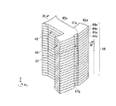
- FIG. 3 is a perspective view showing the core piece of the present embodiment.
- 4 is a view showing the plate member of the present embodiment, and is a cross-sectional view taken along the line IV-IV in FIG.
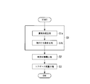
- FIG. 5 is a flowchart showing the procedure of the stator core manufacturing method of the present embodiment.
- FIG. 6 is a cross-sectional view showing a part of the procedure of the stator core manufacturing method of the present embodiment.
- FIG. 7 is a plan view showing a part of the procedure of the stator core manufacturing method of the present embodiment.
- FIG. 8 is a plan view showing a modified core piece.
- the Z axis is shown as appropriate.
- the Z-axis direction is a direction parallel to the axial direction of the central axis J shown in FIG.
- the direction in which the central axis J extends (Z-axis direction) is the vertical direction.
- the positive side (+ Z side) in the Z-axis direction is referred to as “upper side”
- the negative side ( ⁇ Z side) in the Z-axis direction is referred to as “lower side”.
- the up-down direction, the upper side, and the lower side are names used for explanation only, and do not limit the actual positional relationship and direction.
- a direction parallel to the central axis J (Z-axis direction) is simply referred to as an “axial direction”, and a radial direction around the central axis J is simply referred to as a “radial direction”.
- the circumferential direction ( ⁇ Z direction) centered on, that is, the axis around the central axis J is simply referred to as “circumferential direction”.
- the term “extending in the axial direction” includes not only strictly extending in the axial direction but also extending in a direction inclined with respect to the axial direction within a range of less than 45 °. Further, in this specification, the term “extend in the radial direction” means that it is strictly inclined in the range of less than 45 ° with respect to the radial direction in addition to the case of extending in the radial direction, that is, the direction perpendicular to the axial direction. This includes cases extending in the other direction.
- FIG. 1 is a sectional view showing a motor 10 of the present embodiment.
- the motor 10 includes a housing 20, a rotor 30, a stator 40, an upper bearing holder 50, a lower bearing (bearing) 61, and an upper bearing (bearing) 62. *
- the housing 20 accommodates the rotor 30, the stator 40, the upper bearing holder 50, the lower bearing 61, and the upper bearing 62.
- the housing 20 includes a housing cylinder portion 21, a housing bottom plate portion 22, a lower bearing holding portion 23, and a housing top plate portion 24.
- the housing cylinder portion 21 has a cylindrical shape surrounding the stator 40 in the circumferential direction.
- the housing bottom plate portion 22 is connected to the lower end portion of the housing tube portion 21.
- the housing bottom plate portion 22 covers the lower side of the stator 40.
- the housing bottom plate portion 22 has an output shaft hole 22a that penetrates the housing bottom plate portion 22 in the axial direction.
- the output shaft hole 22 a is located at the center of the housing bottom plate portion 22. *
- the lower bearing holding portion 23 has a cylindrical shape protruding upward from the housing bottom plate portion 22.
- the lower bearing holding portion 23 is located on the radially outer side than the output shaft hole 22a.
- a lower bearing 61 is held inside the lower bearing holding portion 23 in the radial direction.
- the housing top plate portion 24 is connected to the upper end portion of the housing tube portion 21.
- the housing top plate portion 24 covers the rotor 30, the stator 40, and the upper bearing holder 50. *
- the rotor 30 includes a shaft 31, a rotor core 32, and a rotor magnet 33.
- the shaft 31 is centered on a central axis J extending in the vertical direction.
- the lower end of the shaft 31 protrudes outside the housing 20 through the output shaft hole 22a.
- the rotor core 32 is fixed to the outer peripheral surface of the shaft 31.
- the rotor magnet 33 is fixed to the outer peripheral surface of the rotor core 32.
- the shaft 31, the rotor core 32, and the rotor magnet 33 all rotate around the central axis ( ⁇ ⁇ Z direction). *
- the lower bearing 61 and the upper bearing 62 are bearings that support the shaft 31.
- the lower bearing 61 and the upper bearing 62 support the shaft 31 so as to be rotatable around the central axis J ( ⁇ ⁇ Z direction).
- the lower bearing 61 is located below the stator 40.
- the lower bearing 61 is held by the lower bearing holding portion 23.
- the upper bearing 62 is located above the stator 40.
- the upper bearing 62 is held by the upper bearing holder 50. *
- the upper bearing holder 50 is located above the stator 40.
- the upper bearing holder 50 is fixed to the inner peripheral surface of the housing cylinder portion 21.
- the upper bearing holder 50 holds the upper bearing 62. *
- the stator 40 is located on the radially outer side of the rotor 30.
- the stator 40 includes a stator core 41, an insulator 42, and a coil 43.
- the insulator 42 is attached to a later-described tooth 46 of the stator core 41.
- the coil 43 is wound around the tooth 46 via the insulator 42.
- FIG. 2 is a plan view showing the stator core 41.
- the stator core 41 has a plurality of core pieces 44.
- the plurality of core pieces 44 are arranged along a circumferential direction around a central axis J extending in the up-down direction.
- the core pieces 44 are separate members, for example. That is, the stator core 41 is a split core.
- FIG. 3 is a perspective view showing the core piece 44. As shown in FIGS. 1 to 3, the core piece 44 includes a core back 45, a tooth 46, and a groove 47. *
- the core back 45 extends in the circumferential direction.
- the circumferential end of the core back 45 is connected to the core back 45 of the core piece 44 adjacent in the circumferential direction.
- the plurality of core backs 45 have an annular shape surrounding the rotor 30 in the circumferential direction.
- the core back 45 is fixed to the inner peripheral surface of the housing cylindrical portion 21.
- the teeth 46 extend radially inward from the core back 45.
- An insulator 42 and a coil 43 are attached to the tooth 46. *
- the groove 47 is recessed radially inward from the radially outer surface of the core back 45. As shown in FIG. 3, the groove 47 is provided over the entire axial direction of the core piece 44.
- the groove 47 is, for example, a jig fitting groove into which a positioning jig is fitted.
- the groove 47 is used for positioning the plurality of core pieces 44 in the circumferential direction.
- the plurality of core pieces 44 are formed by laminating a plurality of plate members 44a.
- the plate member 44a is manufactured by punching out an electromagnetic steel plate. The manufacturing method of the plate member 44a will be described in detail later.
- the plate member 44a includes a core back portion 45a, a teeth portion 46a, and a groove portion 47a.
- the core back portion 45a extends in the circumferential direction.
- the teeth portion 46a extends radially inward (one radial direction side) from the core back portion 45a.
- the groove portion 47a is recessed inward in the radial direction from the radially outer surface (the other radial direction side) of the core back portion 45a.
- the entire groove portion 47a overlaps with the tooth portion 46a in the radial direction. Therefore, it is easy to provide the groove 47 at the center in the circumferential direction of the core back 45. Thereby, it is easy to position the core piece 44 in the circumferential direction using the groove 47. Therefore, as a result, the arrangement accuracy in the circumferential direction of the plurality of core pieces 44 can be improved, and distortion of the magnetic path generated in the stator core 41 can be suppressed. As a result, the cogging torque and torque ripple of the motor 10 can be suppressed from increasing. *
- the circumferential center of the groove 47a overlaps the circumferential center of the tooth portion 46a in the radial direction. That is, the circumferential position at the center in the circumferential direction of the groove portion 47a is the same as the circumferential position at the center in the circumferential direction of the tooth portion 46a. Therefore, the groove 47 can be provided at the center in the circumferential direction of the core back 45. Thereby, it is easy to position the core piece 44 in the circumferential direction using the groove 47. Therefore, as a result, the arrangement accuracy of the plurality of core pieces 44 in the circumferential direction can be further improved, and the distortion of the magnetic path generated in the stator core 41 can be further suppressed. As a result, the cogging torque and torque ripple of the motor 10 can be suppressed from increasing.
- the shape of the groove 47a in plan view is not particularly limited, and may be a semicircular shape, a semi-elliptical shape, a triangular shape, a quadrangular shape, or other polygonal shapes. Also good.
- the planar view shape of the groove 47a is, for example, a rectangular shape. Therefore, it is easy to make the groove 47a.
- the shape of a member fitted into the groove 47 constituted by the plurality of groove portions 47a for example, a positioning jig can be simplified. *
- the edge 47g on the radially outer side (the other side in the radial direction) of the groove 47a is an angular corner.
- the radially outer edge of the groove 47a is rounded.
- the edge portion 47g of the groove portion 47a can be formed into an angular corner.
- edge 47g is an angled corner
- a manufacturing method to be described later can be employed in which the portion other than the groove 47a of the plate member 44a and the groove 47a are formed by separate punching steps. Thereby, it can suppress that the dimensional accuracy of the groove part 47a falls as a result.
- the plate member side surface 44b which is the side surface of the plate member 44a has a shear surface and a fracture surface along the axial direction.
- the plate member side surface 44b includes a core back portion side surface 45b that is a side surface of the core back portion 45a, a teeth portion side surface 46b that is a side surface of the teeth portion 46a, and a groove portion inner side surface 47b that is an inner surface of the groove portion 47a.
- the core back part side surface 45b has the shear surface 45c and the fracture surface 45d along an axial direction.
- the teeth side surface 46b has a shear surface 46c and a fracture surface 46d along the axial direction.
- the groove inner surface 47b has a shear surface 47c and a fracture surface 47d along the axial direction.
- the shear surfaces 45c, 46c, 47c are, for example, surfaces parallel to the axial direction.
- the fracture surfaces 45d, 46d, and 47d are surfaces that are inclined with respect to the axial direction. *
- the shear surface 45c is located above the fracture surface 45d.
- the shear surface 46c is located above the fracture surface 46d.
- the shear surface 47c is positioned below the fracture surface 47d. That is, the shear surface 47c is located below the fracture surface 47d on the inner surface of the groove 47a in the plate member side surface 44b.
- the shear surfaces 45c and 46c are positioned above the fracture surfaces 45d and 46d.
- the side surface of the part punched from the magnetic steel sheet and the inner side surface of the hole formed by punching a part of the electromagnetic steel sheet The axial position of the fracture surface is upside down. That is, for example, on the side surface of the part punched from the electromagnetic steel sheet, the shear surface is located above the fracture surface, and on the inner side surface of the hole generated by punching a part of the electromagnetic steel sheet, the shear surface is the fracture surface. Located on the underside. *
- the entire plate member is a part that is punched out, so that the axial positions of the shear surface and the fracture surface are the same on the entire side surface of the plate member.
- the axial positions of the shear surface and the fracture surface are vertically changed between the portion of the plate member side surface 44b excluding the inner surface of the groove portion 47a and the inner surface of the groove portion 47a.
- the manufacturing method mentioned later which forms parts other than the groove part 47a of the board member 44a and the groove part 47a by a separate punching process is employable. Thereby, it can suppress that the dimensional accuracy of the groove part 47a falls.
- the core back portion side surface 45b includes, for example, a sagging 45e and a burr 45f.
- the sagging 45e is located at the upper end of the core back side surface 45b. That is, the sagging 45e is located above the shearing surface 45c.
- the sagging 45e is a portion with a smooth rounded upper edge of the core back portion 45a.
- the burr 45f is located at the lower end of the core back side surface 45b. That is, the burr 45f is located below the fracture surface 45d. The burr 45f is a portion protruding downward. *
- the teeth side surface 46b includes, for example, a sagging 46e and a burr 46f.
- the sag 46e is the same as the sag 45e on the core back side surface 45b.
- the burr 46f is the same as the burr 45f on the core back side surface 45b.
- the groove inner side surface 47b includes, for example, a sagging 47e and a burr 47f.
- the sagging 47e is located at the lower end of the groove inner surface 47b. That is, the sagging 47e is located below the shearing surface 47c.
- the sagging 47e is a portion where the lower edge of the groove 47a is smoothly rounded.
- the burr 47f is located at the upper end of the groove inner surface 47b. That is, the burr 47f is positioned above the fracture surface 47d. The burr 47f is a portion protruding upward. *
- the sagging 45e, 46e, 47e and the burrs 45f, 46f, 47f are generated, for example, on the side surface of the part punched from the electromagnetic steel sheet and the inner side surface of the hole generated by punching a part of the electromagnetic steel sheet.
- the sag, shear surface, fracture surface, and burr are in this order along the axial direction. Arise. *
- the side surface of the plate member 44a includes a surface that intersects a surface of the plate members that overlap each other.
- the surfaces on which the plate members 44a are superimposed are, for example, surfaces orthogonal to the axial direction, that is, the upper surface and the lower surface of the plate member 44a. That is, the side surface of the plate member 44a includes, for example, surfaces other than the upper surface and the lower surface of the plate member 44a.
- FIG. 5 is a flowchart showing a procedure of a method for manufacturing the stator core 41 of the present embodiment.
- the method for manufacturing the stator core 41 of the present embodiment includes a plate member manufacturing step S1, a plate member stacking step S2, and a core piece arranging step S3. *
- the plate member manufacturing step S1 is a step of manufacturing the plate member 44a.
- the plate member manufacturing step S1 includes a groove forming step S1a and a piece punching step S1b. That is, the method for manufacturing the stator core 41 of the present embodiment includes a groove forming step S1a and a piece punching step S1b.
- the groove forming process S1a and the piece punching process S1b are performed in this order. That is, in this embodiment, the piece punching step S1b is provided after the groove forming step S1a.
- FIGS. 7A and 7B are cross-sectional views showing a part of the procedure of the plate member manufacturing step S1.
- FIG. 6A is a view showing the groove forming step S1a.
- 6 (B) and 6 (C) are views showing the piece punching step S1b.
- FIG. 7A is a plan view showing the electromagnetic steel sheet 70 after the groove forming step S1a is completed.
- FIG. 7B is a plan view showing the electromagnetic steel sheet 70 after the piece punching step S1b is completed. *
- the plate member 44a is manufactured by punching out the electromagnetic steel sheet 70 using the punches 81 and 83 and the die 80.
- the piece punching step S1b and the groove forming step S1a are punching steps using the punches 81 and 83 and the die 80.
- the die 80 is, for example, a progressive die.
- the groove forming step S1a is a step of punching a part of the electromagnetic steel sheet 70 to form the groove 47a.
- the electromagnetic steel sheet 70 is disposed on the upper surface of the die 80.
- the pressing member 82 is disposed on the upper surface of the electromagnetic steel sheet 70, and the electromagnetic steel sheet 70 is sandwiched between the die 80 and the pressing member 82.
- the punch 81 is passed through the first punching hole 80 a of the die 80, and the removed piece 71 that is a part of the electromagnetic steel sheet 70 is punched out. Thereby, a hole 70 a is formed on the electromagnetic steel plate 70.
- the hole 70a includes a groove 47a. That is, in the groove forming step S1a of the present embodiment, a part of the electromagnetic steel plate 70 is punched to form the hole 70a including the groove 47a on the electromagnetic steel plate 70.
- the planar view shape of the hole 70a is, for example, a rectangular shape. That is, the planar view shape of the first punching hole 80a and the planar view shape of the punch 81 are, for example, rectangular.
- the plan view shape of the hole 70a, the plan view shape of the first punching hole 80a, and the plan view shape of the punch 81 are not particularly limited as long as the groove portion 47a can be formed. *
- the piece punching step S1b is a step of punching the piece 72 including the core back portion 45a and the teeth portion 46a from the electromagnetic steel sheet 70.
- the electromagnetic steel sheet 70 is arranged at a position where the inner edge of the second punching hole 80b of the die 80 on the upper surface of the die 80 overlaps with the hole 70a in the axial direction. To do. *
- the magnetic steel sheet 70 is automatically positioned at a predetermined position after the groove forming step S1a, that is, the inner edge of the second punched hole 80b is aligned with the hole 70a. Sent to a position that overlaps the direction.
- the pressing member 82 is disposed on the upper surface of the electromagnetic steel sheet 70, and the electromagnetic steel sheet 70 is sandwiched between the die 80 and the pressing member 82.
- the punch 83 is passed through the second punching hole 80b, and the piece 72 that is a part of the electromagnetic steel sheet 70 is punched out.
- the plan view shape of the second punching hole 80b and the plan view shape of the punch 83 are the same as the shape of the plate member 44a excluding the groove 47a.
- the outer peripheral shape of the punch 83 overlaps the hole 70a.
- the piece 72 includes a groove 47a that is a part of the hole 70a. That is, in the individual piece punching step S1b of this embodiment, the individual piece 72 including a part of the hole 70a in the electromagnetic steel sheet 70 is punched. In this embodiment, the piece 72 is a plate member 44a. As shown in FIG. 7B, the other part of the hole 70a remains on the electromagnetic steel sheet 70 together with the punched hole 70b generated by punching the piece 72. *
- the size of the portion punched from the electromagnetic steel sheet 70 is determined by the size of the die blade, that is, the die punching hole.
- the size of the hole produced by punching a part of the electromagnetic steel sheet 70 is determined by the punch blade, that is, the size of the punch.
- the case where the dimension of the predetermined object generated by the punching process is determined by the dimension of the die blade is expressed as forming the predetermined object using the die blade. Further, in the present specification, the case where the dimension of the predetermined target generated by the punching process is determined by the dimension of the punch blade is expressed as forming using the punch blade.
- a groove 47a is formed by the punch 81 and the first punching hole 80a.
- the dimension of the groove 47 a is determined by the dimension of the blade of the punch 81. That is, in the groove forming step S1a of the present embodiment, the groove 47a is formed using the blade of the punch 81.
- the individual piece 72 is formed by the punch 83 and the second punching hole 80b.
- the size of the piece 72 is determined by the size of the blade of the die 80. That is, in the piece punching step S1b of the present embodiment, the pieces 72 are formed using the blades of the die 80.
- the punch blade and the die blade are worn each time the electromagnetic steel sheet 70 is punched. Therefore, it is necessary to grind the punch blade and the die blade periodically.
- the die blade is provided with a gradient inclined to the outside of the die punching hole from the lower side to the upper side. Therefore, the position of the die blade gradually changes outward each time the die blade is ground, resulting in an increase in the size of the die blade.
- the punch blade is linear along the vertical direction, the dimensions do not change even if the blade is ground many times.
- the entire plate member 44 a when the entire plate member 44 a is punched from the electromagnetic steel sheet 70 in a single punching process, the entire plate member 44 a including the outer peripheral shape of the groove 47 a is a portion that is punched from the electromagnetic steel sheet 70. Therefore, the core back part 45a, the teeth part 46a, and the groove part 47a are all formed using a die blade. That is, the dimension of the groove 47a is determined by the dimension of the die blade. Thereby, the dimension of the groove part 47a becomes large and the dimensional accuracy of the groove part 47a decreases as the die blade is ground to increase the dimension. Therefore, the dimensional accuracy of the groove 47 of the core piece 44 configured by stacking the groove portions 47a is lowered. *
- the groove 47 is used as a jig fitting groove of a positioning jig when the plurality of core pieces 44 are arranged in an annular shape. That is, the plurality of core pieces 44 are arranged in an annular shape with the groove 47 as a reference. Therefore, if the dimensional accuracy of the groove 47 is low, the circumferential accuracy of the core piece 44 is lowered. As a result, there is a problem that the magnetic path generated in the stator core 41 is distorted and the cogging torque and torque ripple of the motor 10 are increased. *
- a groove portion forming step S1a there are two punching steps, a groove portion forming step S1a and an individual piece punching step S1b.
- the groove portion forming step S1a a part of the electromagnetic steel sheet 70 is punched to form the groove portion 47a.
- a processing method for forming the groove 47a using the blade of the punch 81 can be employed. That is, the dimension of the groove 47a can be determined by the dimension of the blade of the punch 81.
- the portion remaining inside the punched-out frame-like portion can be made the plate member 44a.
- the inner edge of the hole produced by partly punching from the electromagnetic steel sheet 70 is the outer peripheral shape of the plate member 44a. That is, according to this method, the plate member 44a can be formed using a punch blade. Therefore, it can suppress that the dimensional accuracy of the groove part 47a falls.
- the shape of the plate member 44a is not a simple shape such as a square shape or a circular shape, it is difficult to manufacture a punch that punches a frame shape having the outer peripheral shape of the plate member 44a as an inner edge.
- the pieces 72 other than the groove portions 47a that is, the pieces 72 including the core back portion 45a and the teeth portion 46a are punched from the electromagnetic steel sheet 70. Therefore, the piece 72 is formed using the blade of the die 80. Thereby, according to this embodiment, it can suppress that the dimensional accuracy of the groove part 47a falls, making the shape of punch 81,83 simple.
- the groove portion 47a and the individual piece 72 are formed by using the blades of the punches 81 and 82 and the blade of the die 80, respectively, so that the groove portion can be easily manufactured at low cost.
- the plate member 44a having excellent dimensional accuracy of 47a can be manufactured.
- the piece punching step S1b is provided before the groove forming step S1a, the area for holding the pieces punched in the piece punching step S1b is small. Therefore, in the groove forming step S1a, it may be difficult to stably hold the individual pieces, and it may be difficult to form the groove 47a with high positional accuracy. As a result, the position of the groove 47a tends to vary for each plate member 44a, and as a result, the magnetic path generated in the stator core 41 tends to be distorted. Moreover, the manufacturing apparatus of the plate member 44a is likely to be complicated, and the cost is likely to increase. *
- the piece punching step S1b is provided after the groove forming step S1a. Therefore, in the groove forming step S1a and the individual piece punching step S1b, the electromagnetic steel plate 70 can be easily and stably held by the pressing member 82 and the die 80. Thereby, the groove part 47a can be formed with high positional accuracy. As a result, distortion of the magnetic path generated in the stator core 41 can be suppressed. Moreover, it can suppress that the manufacturing apparatus of the plate member 44a becomes complicated. *
- the individual piece punching step S1b is provided after the groove portion forming step S1a, so that the individual piece 72 can be punched based on the groove portion 47a in the individual piece punching step S1b.
- the plate member stacking step S2 is a step of stacking a plurality of plate members 44a. By this step, the core piece 44 shown in FIG. 3 can be formed. *
- positioning process S3 is a process of arrange
- the groove 47 is used as a jig fitting groove of a positioning jig. Thereby, the core piece 44 can be arrange
- the stator core 41 of the present embodiment is manufactured by the plate member manufacturing step S1, the plate member stacking step S2, and the core piece arranging step S3.
- a step of inspecting the dimension of the plate member 44a may be provided after the plate member manufacturing step S1 and before the plate member stacking step S2. In this step, the dimension of the plate member 44a is measured based on the dimension of the groove 47a. That is, the inspection method of the stator core 41 manufactured using the above-described stator core manufacturing method includes a step of measuring the dimension of the plate member 44a on the basis of the dimension of the groove 47a.
- the overall size of the plate member 44a including the groove 47a increases as the die blade size increases.
- a defective product having a dimension larger than a prescribed value may be mixed in the plate member 44 a constituting the core piece 44.
- the change of the dimension of the groove part 47a since the change of the dimension of the groove part 47a can be suppressed, the change amount of the dimension of the whole plate member 44a is accurately determined by using the dimension of the groove part 47a as a reference. It's easy to do.
- inspection method of the stator core 41 is provided, and the manufactured plate member 44a is accurately made into a good article and a defective article And can be divided into Therefore, it is possible to suppress variation in the dimensional accuracy of the core piece 44 by forming the core piece 44 using only the plate member 44a determined to be non-defective. As a result, variation in the characteristics of the motor 10 can be suppressed.
- the dimension of the plate member 44a can be measured with high accuracy, the change in the dimension of the blade of the die 80 can be determined more accurately. Therefore, it is possible to appropriately determine when to replace the die 80.
- a method of punching the piece 72 including at least a part of the hole 70a in the electromagnetic steel sheet 70 can be employed. That is, in the individual piece punching step S1b of the present embodiment, the individual piece 72 including the entire hole 70a in the electromagnetic steel sheet 70 may be punched. In this case, the whole hole part 70a formed by groove part formation process S1a becomes the groove part 47a.
- the groove forming step S1a may be provided after the piece punching step S1b.
- the part of the electromagnetic steel sheet 70 punched in the groove forming step S1a is a part of the piece (electromagnetic steel sheet) punched in the individual punching process S1b.
- a configuration in which at least a part of the groove portion 47a overlaps with the tooth portion 46a in the radial direction can be employed. That is, in the present embodiment, only a part of the groove portion 47a may overlap the teeth portion 46a in the radial direction.
- the specific method for the groove forming step S1a and the piece punching step S1b is not particularly limited. That is, in the groove forming step S1a, a part of the electromagnetic steel sheet 70 may be punched by any method as long as a part of the electromagnetic steel sheet 70 can be punched to form the groove 47a. In the piece punching step S1b, as long as the piece 72 including the core back portion 45a and the tooth portion 46a is punched from the electromagnetic steel sheet 70, the piece 72 may be punched by any method. *
- the stator core 41 is a split core, but is not limited thereto.
- the stator core 41 may be a straight core in which a plurality of core pieces 44 are connected.
- the plate member to which the plurality of plate members 44a are connected is manufactured by punching from the electromagnetic steel sheet 70, and the connected plate members are stacked to manufacture a member in which the plurality of core pieces 44 are connected to each other. Then, the stator core 41 is manufactured by bending a member in which a plurality of core pieces 44 are connected to each other into an annular shape.
- the dimensional accuracy of the groove 47 can be suppressed from decreasing as described above, even if the stator core 41 is a straight core, the arrangement accuracy of each core piece 44 is high. It can suppress that it falls. Thereby, it can suppress that the magnetic path which arises in the stator core 41 is distorted, and can suppress that the cogging torque and torque ripple of the motor 10 become large.
- stator core 41 is a straight core
- stator core 41 is a single member. That is, the plurality of core pieces 44 are, for example, part of a single member.
- the motor to which the present invention is applied is not particularly limited.
- the motor 10 is an inner rotor type motor.
- the present invention may be applied to, for example, an outer rotor type motor.
- the groove portion 47a of the plate member 44a is recessed, for example, radially outward from the radially inner surface of the core back portion 45a.
- FIG. 8 is a plan view of a stator core 411 according to a modification.
- the groove 471 has a larger opening toward the radially outer side on the radially outer side.
- the stator core 411 includes a plurality of core pieces 441.
- the core piece 441 is formed by stacking a plurality of plate members 441a, and the plate member 441a includes an enlarged portion 471h that enlarges the opening of the groove portion 471a.
- the enlarged portion 471h enlarges the opening toward the outside. Therefore, it is easy to insert an assembly jig into the groove 471 when the core piece 441a is annularly arranged after the plate members 441a are stacked to form the core piece 441a.
- the opening portion of the groove 471 is inclined so as to expand outward, the assembly jig can be easily inserted. *
- burrs may occur at the edge 47g. This is because burrs are likely to occur at a portion where the cross section punched out in the groove forming step S1a and the cross section punched out in the piece punching step S1b intersect.
- the plate member 441a includes a first edge 471g on the radially inner side of the enlarged portion 471h and a second edge 471i on the radially outer side of the enlarged portion 471h.
- the enlarged portion 471h is formed by being punched in the piece punching step S1b. Therefore, in the modification of FIG. 8, a portion where the cross section punched in the groove forming step S1a and the cross section punched in the piece punching step S1b intersect is the first edge portion 471g.
- the first edge portion 471g is formed on the inner side of the core back portion side surface 451b, the possibility of contacting the housing when assembling the motor is reduced. *
- the second edge portion 471i is also formed at the portion where the enlarged portion 471h and the core back portion side surface 451b intersect.
- the second edge portion 471i is a portion where the cross-sections punched in the same piece punching step S1b intersect, there is little possibility that burrs will occur.
- the second edge portion 471i is a portion where the cross sections punched in the piece punching step S1b intersect, the second edge portion 471i can be formed into an arc shape. If the second edge 471i has an arc shape, the possibility of further occurrence of burrs is reduced. *
Landscapes
- Engineering & Computer Science (AREA)
- Power Engineering (AREA)
- Manufacturing & Machinery (AREA)
- Manufacture Of Motors, Generators (AREA)
- Iron Core Of Rotating Electric Machines (AREA)
Abstract
本発明のステータコアの製造方法の一つの態様は、上下方向に延びる中心軸を中心とした周方向に沿って配置される複数のコアピースを有し、複数のコアピースは、板部材が複数積層されて形成されており、板部材は、周方向に延びるコアバック部と、コアバック部から径方向一方側に延びるティース部と、コアバック部の径方向他方側の面から径方向一方側に窪む溝部と、を有するステータコアの製造方法であって、コアバック部およびティース部を含む個片を電磁鋼板から打ち抜く個片打ち抜き工程と、電磁鋼板の一部を打ち抜いて溝部を形成する溝部形成工程と、を含む。
Description
本発明は、ステータコアの製造方法、ステータコアの検査方法、ステータコア、およびモータに関する。
例えば、特許文献1には、回転電機のステータに用いる分割コアが記載されている。分割コアの外径側には、位置決めを目的として凹部が設けられる。
上記のような分割コアの製造方法としては、分割コアの外周を有する板部材を電磁鋼板から打ち抜いて、打ち抜いた板部材を積層する方法が挙げられる。この方法を用いた場合、分割コアの外周の寸法精度は、外周全体において同じとなる。
ところで、位置決めに用いられる分割コアの凹部(溝部)は、他の部分に比べて高い寸法精度が求められる。しかし、上記のように、分割コアの外周を有する板部材を電磁鋼板から単に打ち抜く方法では、打ち抜き精度が低下した場合に、他の部分と共に凹部の寸法精度も低下する。そのため、分割コアの位置決めの精度が低下する問題があった。これにより、複数の分割コアによって構成されるステータコアに生じる磁路が歪む虞があった。ステータコアに生じる磁路が歪むと、回転電機(モータ)のコギングトルクおよびトルクリップルが大きくなる問題があった。
上記の問題は、分割コアに限られず、例えば、複数のコアピースが連結されたストレートコアについても同様である。ストレートコアの場合、複数のコアピースが連結された部材を円環状に折り曲げて、複数のコアピースを周方向に沿って配置する。このとき、コアピースごとに設けられた位置決めに用いられる凹部の寸法精度が低いと、各コアピースの位置決め精度が低下する問題があった。
本発明の一つの態様は、上記問題点に鑑みて、位置決めに用いられる溝部の寸法精度が低下することを抑制できるステータコアの製造方法、およびそのような製造方法を用いて製造されたステータコアの検査方法を提供することを目的の一つとする。また、本発明の一つの態様は、位置決めに用いられる溝部の寸法精度が低下することを抑制できるステータコアの製造方法を用いて製造されたステータコア、およびそのようなステータコアを備えるモータを提供することを目的の一つとする。
本発明のステータコアの製造方法の一つ態様は、上下方向に延びる中心軸を中心とした周方向に沿って配置される複数のコアピースを有し、前記複数のコアピースは、板部材が複数積層されて形成されており、前記板部材は、周方向に延びるコアバック部と、前記コアバック部から径方向一方側に延びるティース部と、前記コアバック部の径方向他方側の面から前記径方向一方側に窪む溝部と、を有するステータコアの製造方法であって、前記コアバック部および前記ティース部を含む個片を電磁鋼板から打ち抜く個片打ち抜き工程と、前記電磁鋼板の一部を打ち抜いて前記溝部を形成する溝部形成工程と、を含む。
本発明の一つの態様によれば、位置決めに用いられる溝部の寸法精度が低下することを抑制できるステータコアの製造方法、およびそのような製造方法を用いて製造されたステータコアの検査方法が提供される。また、本発明の一つの態様によれば、位置決めに用いられる溝部の寸法精度が低下することを抑制できるステータコアの製造方法を用いて製造されたステータコア、およびそのようなステータコアを備えるモータが提供される。
以下、図面を参照しながら、本発明の実施形態に係るモータ、およびステータコアの製造方法について説明する。なお、本発明の範囲は、以下の実施の形態に限定されず、本発明の技術的思想の範囲内で任意に変更可能である。また、以下の図面においては、各構成をわかりやすくするために、各構造における縮尺および数等を、実際の構造における縮尺および数等と異ならせる場合がある。
また、図面においては、適宜Z軸を示す。Z軸方向は、図1に示す中心軸Jの軸方向と平行な方向とする。また、以下の説明においては、中心軸Jの延びる方向(Z軸方向)を上下方向とする。Z軸方向の正の側(+Z側)を「上側」と呼び、Z軸方向の負の側(-Z側)を「下側」と呼ぶ。なお、上下方向、上側および下側とは、単に説明のために用いられる名称であって、実際の位置関係や方向を限定しない。また、特に断りのない限り、中心軸Jに平行な方向(Z軸方向)を単に「軸方向」と呼び、中心軸Jを中心とする径方向を単に「径方向」と呼び、中心軸Jを中心とする周方向(θZ方向)、すなわち、中心軸Jの軸周りを単に「周方向」と呼ぶ。
なお、本明細書において、軸方向に延びる、とは、厳密に軸方向に延びる場合に加えて、軸方向に対して、45°未満の範囲で傾いた方向に延びる場合も含む。また、本明細書において、径方向に延びる、とは、厳密に径方向、すなわち、軸方向に対して垂直な方向に延びる場合に加えて、径方向に対して、45°未満の範囲で傾いた方向に延びる場合も含む。
<モータ> 図1は、本実施形態のモータ10を示す断面図である。図1に示すように、モータ10は、ハウジング20と、ロータ30と、ステータ40と、上側ベアリングホルダ50と、下側ベアリング(ベアリング)61と、上側ベアリング(ベアリング)62と、を備える。
[ハウジング] ハウジング20は、ロータ30と、ステータ40と、上側ベアリングホルダ50と、下側ベアリング61と、上側ベアリング62と、を収容する。ハウジング20は、ハウジング筒部21と、ハウジング底板部22と、下側ベアリング保持部23と、ハウジング天板部24と、を有する。
ハウジング筒部21は、ステータ40を周方向に囲む筒状である。ハウジング底板部22は、ハウジング筒部21の下側の端部に接続される。ハウジング底板部22は、ステータ40の下側を覆う。ハウジング底板部22は、ハウジング底板部22を軸方向に貫通する出力軸孔22aを有する。出力軸孔22aは、ハウジング底板部22の中央に位置する。
下側ベアリング保持部23は、ハウジング底板部22から上側に突出する筒状である。下側ベアリング保持部23は、出力軸孔22aよりも径方向外側に位置する。下側ベアリング保持部23の径方向内側には、下側ベアリング61が保持される。ハウジング天板部24は、ハウジング筒部21の上側の端部に接続される。ハウジング天板部24は、ロータ30、ステータ40、および上側ベアリングホルダ50の上側を覆う。
[ロータ] ロータ30は、シャフト31と、ロータコア32と、ロータマグネット33と、を有する。シャフト31は、上下方向に延びる中心軸Jを中心とする。シャフト31の下側の端部は、出力軸孔22aを介してハウジング20の外部に突出する。
ロータコア32は、シャフト31の外周面に固定される。ロータマグネット33は、ロータコア32の外周面に固定される。シャフト31と、ロータコア32と、ロータマグネット33とは、共に中心軸周り(±θZ方向)に回転する。
[下側ベアリングおよび上側ベアリング] 下側ベアリング61および上側ベアリング62は、シャフト31を支持するベアリングである。下側ベアリング61および上側ベアリング62は、シャフト31を中心軸J周り(±θZ方向)に回転可能に支持する。下側ベアリング61は、ステータ40よりも下側に位置する。下側ベアリング61は、下側ベアリング保持部23に保持される。上側ベアリング62は、ステータ40よりも上側に位置する。上側ベアリング62は、上側ベアリングホルダ50に保持される。
[上側ベアリングホルダ] 上側ベアリングホルダ50は、ステータ40の上側に位置する。上側ベアリングホルダ50は、ハウジング筒部21の内周面に固定される。上側ベアリングホルダ50は、上側ベアリング62を保持する。
[ステータ] ステータ40は、ロータ30の径方向外側に位置する。ステータ40は、ステータコア41と、インシュレータ42と、コイル43と、を有する。インシュレータ42は、ステータコア41の後述するティース46に装着される。コイル43は、インシュレータ42を介してティース46に巻き回される。
図2は、ステータコア41を示す平面図である。図2に示すように、ステータコア41は、複数のコアピース44を有する。複数のコアピース44は、上下方向に延びる中心軸Jを中心とした周方向に沿って配置される。コアピース44は、例えば、互いに別部材である。すなわち、ステータコア41は、分割コアである。
図3は、コアピース44を示す斜視図である。図1から図3に示すように、コアピース44は、コアバック45と、ティース46と、溝47と、を有する。
コアバック45は、周方向に延びる。コアバック45の周方向の端部は、周方向に隣り合うコアピース44のコアバック45と連結される。これにより、複数のコアバック45は、ロータ30を周方向に囲む円環状となる。図1に示すように、コアバック45は、ハウジング筒部21の内周面に固定される。ティース46は、コアバック45から径方向内側に延びる。ティース46には、インシュレータ42およびコイル43が装着される。
図2に示すように、溝47は、コアバック45の径方向外側の面から径方向内側に窪む。図3に示すように、溝47は、コアピース44の軸方向の全体に亘って設けられる。溝47は、例えば、位置出し治具が嵌め込まれる治具嵌め溝である。溝47は、複数のコアピース44の周方向の位置決めに用いられる。
複数のコアピース44は、板部材44aが複数積層されて形成される。板部材44aは、電磁鋼板を打ち抜いて製造される。板部材44aの製造方法については、後段において詳述する。図2に示すように、板部材44aは、コアバック部45aと、ティース部46aと、溝部47aと、を有する。
図3に示すように、板部材44aが複数積層されることで、コアバック部45aが複数積層されたコアバック45と、ティース部46aが複数積層されたティース46と、溝部47aが複数積層された溝47と、が形成される。
図2に示すように、コアバック部45aは、周方向に延びる。ティース部46aは、コアバック部45aから径方向内側(径方向一方側)に延びる。溝部47aは、コアバック部45aの径方向外側(径方向他方側)の面から径方向内側に窪む。
本実施形態において溝部47aの全体は、ティース部46aと径方向に重なる。そのため、溝47をコアバック45の周方向の中心に設けやすい。これにより、溝47を用いてコアピース44を周方向に位置決めしやすい。したがって、結果として複数のコアピース44の周方向の配置精度を向上でき、ステータコア41に生じる磁路が歪むことを抑制できる。その結果、モータ10のコギングトルクおよびトルクリップルが大きくなることを抑制できる。
本実施形態において溝部
47aの周方向の中心は、ティース部46aの周方向の中心と径方向に重なる。すなわち、溝部47aの周方向の中心の周方向位置と、ティース部46aの周方向の中心の周方向位置とは、同じである。そのため、溝47をコアバック45の周方向の中心に設けることができる。これにより、溝47を用いてコアピース44を周方向により位置決めしやすい。したがって、結果として複数のコアピース44の周方向の配置精度をより向上でき、ステータコア41に生じる磁路が歪むことをより抑制できる。その結果、モータ10のコギングトルクおよびトルクリップルが大きくなることを抑制できる。
47aの周方向の中心は、ティース部46aの周方向の中心と径方向に重なる。すなわち、溝部47aの周方向の中心の周方向位置と、ティース部46aの周方向の中心の周方向位置とは、同じである。そのため、溝47をコアバック45の周方向の中心に設けることができる。これにより、溝47を用いてコアピース44を周方向により位置決めしやすい。したがって、結果として複数のコアピース44の周方向の配置精度をより向上でき、ステータコア41に生じる磁路が歪むことをより抑制できる。その結果、モータ10のコギングトルクおよびトルクリップルが大きくなることを抑制できる。
溝部47aの平面視形状は、特に限定されず、半円形状であっても、半楕円形状であっても、三角形状であっても、四角形状であっても、その他の多角形状であってもよい。図2の例では、溝部47aの平面視形状は、例えば、矩形状である。そのため、溝部47aを作りやすい。また、複数の溝部47aによって構成される溝47に嵌め込まれる部材、例えば位置出し治具の形状を簡単にできる。
図2および図3に示すように、溝部47aの径方向外側(径方向他方側)の縁部47gは、角張った角である。例えば、板部材44aの全体が電磁鋼板から一度に打ち抜かれる場合、溝部47aの径方向外側の縁部は丸みを帯びる。一方、板部材44aの溝部47a以外の部分と溝部47aとを別々の打ち抜き工程によって打ち抜く場合、溝部47aの縁部47gを角張った角とできる。したがって、本実施形態によれば、縁部47gが角張った角であるため、板部材44aの溝部47a以外の部分と溝部47aとを別々の打ち抜き工程によって形成する後述する製造方法を採用できる。これにより、結果として溝部47aの寸法精度が低下することを抑制できる。
図4は、板部材44aを示す図であって、図3におけるIV-IV断面図である。図4に示すように、板部材44aの側面である板部材側面44bは、軸方向に沿って、せん断面と、破断面と、を有する。板部材側面44bは、コアバック部45aの側面であるコアバック部側面45bと、ティース部46aの側面であるティース部側面46bと、溝部47aの内側面である溝部内側面47bと、を含む。
すなわち、コアバック部側面45bは、軸方向に沿って、せん断面45cと、破断面45dと、を有する。ティース部側面46bは、軸方向に沿って、せん断面46cと、破断面46dと、を有する。溝部内側面47bは、軸方向に沿って、せん断面47cと、破断面47dと、を有する。せん断面45c,46c,47cは、例えば、軸方向と平行な面である。破断面45d,46d,47dは、軸方向に対して傾斜する面である。
コアバック部側面45bにおいては、せん断面45cが破断面45dの上側に位置する。ティース部側面46bにおいては、せん断面46cが破断面46dの上側に位置する。溝部内側面47bにおいては、せん断面47cが破断面47dの下側に位置する。すなわち、板部材側面44bのうちの溝部47aの内側面においては、せん断面47cが破断面47dの下側に位置する。板部材側面44bのうちの溝部47aの内側面を除く部分においては、せん断面45c,46cが破断面45d,46dの上側に位置する。
電磁鋼板の一部を例えばダイとパンチとを用いて打ち抜く場合、電磁鋼板から打ち抜かれる部分の側面と、電磁鋼板における一部が打ち抜かれることで生じた孔の内側面と、では、せん断面と破断面との軸方向の位置が上下逆となる。すなわち、例えば、電磁鋼板から打ち抜かれる部分の側面においては、せん断面が破断面の上側に位置し、電磁鋼板における一部が打ち抜かれることで生じた孔の内側面においては、せん断面が破断面の下側に位置する。
例えば、板部材を一度の打ち抜き工程で打ち抜く場合、板部材の全体が打ち抜かれる部分となるため、板部材側面の全体においてせん断面と破断面との軸方向の位置は同じとなる。
これに対して、本実施形態によれば、板部材側面44bのうちの溝部47aの内側面を除く部分と、溝部47aの内側面と、ではせん断面と破断面との軸方向の位置が上下逆である。そのため、板部材44aの溝部47a以外の部分と溝部47aとを別々の打ち抜き工程で形成する後述する製造方法を採用できる。これにより、溝部47aの寸法精度が低下することを抑制できる。
コアバック部側面45bは、例えば、ダレ45eと、バリ45fと、を有する。ダレ45eは、コアバック部側面45bの上側の端部に位置する。すなわち、ダレ45eは、せん断面45cの上側に位置する。ダレ45eは、コアバック部45aの上側の縁が滑らかな丸みを帯びた部分である。
バリ45fは、コアバック部側面45bの下側の端部に位置する。すなわち、バリ45fは、破断面45dの下側に位置する。バリ45fは、下側に突出する部分である。
ティース部側面46bは、例えば、ダレ46eと、バリ46fと、を有する。ダレ46eは、コアバック部側面45bのダレ45eと同様である。バリ46fは、コアバック部側面45bのバリ45fと同様である。
溝部内側面47bは、例えば、ダレ47eと、バリ47fと、を有する。ダレ47eは、溝部内側面47bの下側の端部に位置する。すなわち、ダレ47eは、せん断面47cの下側に位置する。ダレ47eは、溝部47aの下側の縁が滑らかな丸みを帯びた部分である。
バリ47fは、溝部内側面47bの上側の端部に位置する。すなわち、バリ47fは、破断面47dの上側に位置する。バリ47fは、上側に突出する部分である。
ダレ45e,46e,47eと、バリ45f,46f,47fとは、例えば、電磁鋼板から打ち抜かれる部分の側面、および電磁鋼板における一部が打ち抜かれることで生じた孔の内側面に生じる。この場合、電磁鋼板から打ち抜かれる部分の側面、および電磁鋼板における一部が打ち抜かれることで生じた孔の内側面には、ダレ、せん断面、破断面、バリが軸方向に沿ってこの順で生じる。
なお、本明細書において、板部材44aの側面とは、板部材の面のうち板部材同士が重ね合わされる面と交差する面を含む。板部材44a同士が重ね合わされる面とは、例えば、軸方向と直交する面、すなわち、板部材44aの上面および下面である。すなわち、板部材44aの側面とは、例えば、板部材44aの上面および下面を除く面を含む。
<ステータコアの製造方法> 図5は、本実施形態のステータコア41の製造方法の手順を示すフローチャートである。図5に示すように、本実施形態のステータコア41の製造方法は、板部材製造工程S1と、板部材積層工程S2と、コアピース配置工程S3と、を含む。
板部材製造工程S1は、板部材44aを製造する工程である。板部材製造工程S1は、溝部形成工程S1aと、個片打ち抜き工程S1bと、を含む。すなわち、本実施形態のステータコア41の製造方法は、溝部形成工程S1aと、個片打ち抜き工程S1bと、を含む。本実施形態の板部材製造工程S1において、溝部形成工程S1aと、個片打ち抜き工程S1bと、はこの順で実行される。すなわち、本実施形態において個片打ち抜き工程S1bは、溝部形成工程S1aの後に設けられる。
図6(A)~(C)および図7(A),(B)は、板部材製造工程S1の手順の一部を示す断面図である。図6(A)は、溝部形成工程S1aを示す図である。図6(B),(C)は、個片打ち抜き工程S1bを示す図である。図7(A)は、溝部形成工程S1aが終了した後の電磁鋼板70を示す平面図である。図7(B)は、個片打ち抜き工程S1bが終了した後の電磁鋼板70を示す平面図である。
図6(A)~(C)に示すように、本実施形態の板部材製造工程S1においては、パンチ81,83とダイ80とを用いて、電磁鋼板70を打ち抜くことによって板部材44aを製造する。すなわち、個片打ち抜き工程S1bおよび溝部形成工程S1aは、パンチ81,83とダイ80とを用いた打ち抜き工程である。ダイ80は、例えば、順送金型である。
図6(A)に示すように、溝部形成工程S1aは、電磁鋼板70の一部を打ち抜いて溝部47aを形成する工程である。まず、電磁鋼板70をダイ80の上面に配置する。次に、電磁鋼板70の上面に押さえ部材82を配置して、電磁鋼板70をダイ80と押さえ部材82とで挟持する。
次に、パンチ81をダイ80の第1打ち抜き孔80aに通して、電磁鋼板70の一部である除去個片71を打ち抜く。これにより、電磁鋼板70上に孔部70aが形成される。孔部70aは、溝部47aを含む。すなわち、本実施形態の溝部形成工程S1aにおいては、電磁鋼板70の一部を打ち抜いて、電磁鋼板70上に溝部47aを含む孔部70aを形成する。
図7(A)に示すように、孔部70aの平面視形状は、例えば、矩形状である。すなわち、第1打ち抜き孔80aの平面視形状およびパンチ81の平面視形状は、例えば、矩形状である。なお、孔部70aの平面視形状、第1打ち抜き孔80aの平面視形状およびパンチ81の平面視形状は、溝部47aを形成できるならば、特に限定されない。
図6(B),(C)に示すように、個片打ち抜き工程S1bは、コアバック部45aおよびティース部46aを含む個片72を電磁鋼板70から打ち抜く工程である。まず、図6(B)および図7(A)に示すように、ダイ80の上面におけるダイ80の第2打ち抜き孔80bの内縁が孔部70aと軸方向に重なる位置に、電磁鋼板70を配置する。
本実施形態においては、ダイ80が順送金型であるため、電磁鋼板70は溝部形成工程S1aが終了した後に自動的に所定の位置、すなわち、第2打ち抜き孔80bの内縁が孔部70aと軸方向に重なる位置に送られる。
次に、電磁鋼板70の上面に押さえ部材82を配置して、電磁鋼板70をダイ80と押さえ部材82とで挟持する。次に、パンチ83を第2打ち抜き孔80bに通して、電磁鋼板70の一部である個片72を打ち抜く。図7(A)に示すように、第2打ち抜き孔80bの平面視形状およびパンチ83の平面視形状は、板部材44aから溝部47aを除いた形状と同じである。平面視において、パンチ83の外周形状は、孔部70aと重なる。
個片72は、孔部70aの一部である溝部47aを含む。すなわち、本実施形態の個片打ち抜き工程S1bにおいては、電磁鋼板70における孔部70aの一部を含む個片72を打ち抜く。本実施形態において個片72は、板部材44aである。なお、図7(B)に示すように、孔部70aの他の一部は、個片72が打ち抜かれることで生じる打ち抜き孔部70bと共に電磁鋼板70上に残る。
以上により板部材製造工程S1が終了し、板部材44aが製造される。
本実施形態によれば、位置決めに用いられる溝部47aの寸法精度が低下することを抑制できる。以下、詳細に説明する。
例えば、パンチとダイとを用いた打ち抜き工程では、パンチの刃とダイの刃との間にはクリアランスがあるため、電磁鋼板70から打ち抜かれる部分と、電磁鋼板70の一部が打ち抜かれることで生じる孔部とでは、寸法を決定する刃が異なる。すなわち、電磁鋼板70から打ち抜かれる部分の寸法は、ダイの刃、すなわちダイの打ち抜き孔の寸法で決まる。電磁鋼板70の一部が打ち抜かれることで生じる孔部の寸法は、パンチの刃、すなわちパンチの寸法で決まる。
なお、本明細書においては、打ち抜き工程によって生じた所定の対象の寸法がダイの刃の寸法で決まる場合を、ダイの刃を用いて所定の対象を形成する、と表現する。また、本明細書においては、打ち抜き工程によって生じた所定の対象の寸法がパンチの刃の寸法で決まる場合を、パンチの刃を用いて形成する、と表現する。
例えば、上記説明した溝部形成工程S
1aにおいては、パンチ81と第1打ち抜き孔80aとによって溝部47aが形成される。この場合、溝部47aは、電磁鋼板70の一部が打ち抜かれることで生じる孔部の一部であるため、溝部47aの寸法は、パンチ81の刃の寸法で決まる。すなわち、本実施形態の溝部形成工程S1aにおいては、パンチ81の刃を用いて溝部47aを形成する。
1aにおいては、パンチ81と第1打ち抜き孔80aとによって溝部47aが形成される。この場合、溝部47aは、電磁鋼板70の一部が打ち抜かれることで生じる孔部の一部であるため、溝部47aの寸法は、パンチ81の刃の寸法で決まる。すなわち、本実施形態の溝部形成工程S1aにおいては、パンチ81の刃を用いて溝部47aを形成する。
また、例えば、上記説明した個片打ち抜き工程S1bにおいては、パンチ83と第2打ち抜き孔80bとによって個片72が形成される。この場合、個片72は、電磁鋼板70から打ち抜かれる部分であるため、個片72の寸法は、ダイ80の刃の寸法で決まる。すなわち、本実施形態の個片打ち抜き工程S1bにおいては、ダイ80の刃を用いて個片72を形成する。
パンチの刃およびダイの刃は電磁鋼板70を打ち抜く度に摩耗する。そのため、定期的にパンチの刃およびダイの刃を砥ぐ必要がある。ここで、ダイの刃は打ち抜いた部分を下側に落とすために、下側から上側に向かってダイの打ち抜き孔の外側に傾く勾配が付けられる。そのため、ダイの刃の位置はダイの刃を砥ぐ度に徐々に外側に変化し、その結果ダイの刃の寸法が大きくなる。一方、パンチの刃は、上下方向に沿って直線状であるため、何度刃を砥いでも寸法が変化しない。
例えば、板部材44aの全体を電磁鋼板70から一度の打ち抜き工程で打ち抜く場合、溝部47aの外周形状を含めた板部材44aの全体が、電磁鋼板70から打ち抜かれる部分である。そのため、コアバック部45a、ティース部46aおよび溝部47aは、いずれもダイの刃を用いて形成される。すなわち、溝部47aの寸法は、ダイの刃の寸法によって決まる。これにより、ダイの刃が砥がれて寸法が大きくなる程、溝部47aの寸法が大きくなり、溝部47aの寸法精度が低下する。したがって、溝部47aが積層されて構成されるコアピース44の溝47の寸法精度が低下する。
溝47は、複数のコアピース44を円環状に配置する際に位置出し治具の治具嵌め溝として用いられる。すなわち、複数のコアピース44は、溝47を基準として円環状に配置される。そのため、溝47の寸法精度が低いと、コアピース44の周方向の配置精度が低下する。その結果、ステータコア41に生じる磁路が歪み、モータ10のコギングトルクおよびトルクリップルが大きくなる問題があった。
これに対して、本実施形態によれば溝部形成工程S1aと個片打ち抜き工程S1bとの2つの打ち抜き工程を有しており、溝部形成工程S1aにおいて、電磁鋼板70の一部を打ち抜いて溝部47aを形成する。そのため、溝部形成工程S1aにおいて、例えば、溝部47aをパンチ81の刃を用いて形成する加工方法を採用することができる。すなわち、溝部47aの寸法をパンチ81の刃の寸法で決めることができる。これにより、本実施形態によれば、ダイ80の刃の寸法が変化した場合であっても、溝部47aの寸法精度が低下することを抑制できる。その結果、本実施形態によれば、モータ10のコギングトルクおよびトルクリップルが大きくなることを抑制できる。
また、例えば、板部材44aの全体を電磁鋼板70から打ち抜く場合であっても、ダイの刃を定期的に新品と交換すれば、溝部47aの寸法精度が低下することを抑制できる。しかし、ダイの刃を交換する場合には、ダイ全体を交換する必要があるため、コストが増大する。本実施形態によれば、ダイの刃を交換することなしに、溝部47aの寸法精度が低下することを抑制できるため、コストが増大することを抑制できる。
また、例えば、ダイとパンチとによって電磁鋼板70から板部材44aの外周形状を内縁とする枠状の部分を打ち抜けば、打ち抜いた枠状の部分の内側に残る部分を板部材44aとできる。この場合、電磁鋼板70から一部が打ち抜かれることで生じる孔部の内縁が、板部材44aの外周形状となる。すなわち、この方法によれば、板部材44aをパンチの刃を用いて形成することができる。そのため、溝部47aの寸法精度が低下することを抑制できる。しかし、板部材44aの形状は四角形状および円形状等の単純形状ではないため、板部材44aの外周形状を内縁とする枠状を打ち抜くパンチを製造することは困難である。
これに対して、本実施形態によれば、個片打ち抜き工程S1bにおいて、溝部47a以外の部分、すなわちコアバック部45aおよびティース部46aを含む個片72が電磁鋼板70から打ち抜かれる。そのため、個片72はダイ80の刃を用いて形成される。これにより、本実施形態によれば、パンチ81,83の形状を簡単な形状としつつ、溝部47aの寸法精度が低下することを抑制できる。
以上のように、本実施形態によれば、パンチ81,82の刃とダイ80の刃とをそれぞれ用いて溝部47aおよび個片72を形成することで、低コストで、かつ、簡便に、溝部47aの寸法精度が優れた板部材44aを製造することができる。
また、例えば、個片打ち抜き工程S1bが溝部形成工程S1aの前に設けられる場合、個片打ち抜き工程S1bで打ち抜かれた個片を保持する面積が小さい。そのため、溝部形成工程S1aにおいて、個片を安定して保持しにくく、溝部47aを位置精度よく形成しにくい場合がある。これにより、板部材44aごとに溝部47aの位置がばらつきやすく、結果としてステータコア41に生じる磁路が歪みやすい。また、板部材44aの製造装置が複雑化しやすく、コストが増大しやすい。
これに対して、本実施形態によれば、個片打ち抜き工程S1bは、溝部形成工程S1aの後に設けられる。そのため、溝部形成工程S1aおよび個片打ち抜き工程S1bにおいて、電磁鋼板70を押さえ部材82とダイ80とによって、簡単に、かつ、安定して保持しやすい。これにより、溝部47aを位置精度よく形成することができる。その結果、ステータコア41に生じる磁路が歪むことを抑制できる。また、板部材44aの製造装置が複雑化することを抑制できる。
また、本実施形態によれば、個片打ち抜き工程S1bが、溝部形成工程S1aの後に設けられることで、個片打ち抜き工程S1bにおいて、溝部47aを基準として個片72を打ち抜くことができる。上述したように本実施形態によれば溝部47aの寸法精度が低下することを抑制できる。そのため、溝部47aを基準とすることで、板部材44aにおける溝部47aの位置精度を向上できる。
板部材積層工程S2は、複数の板部材44aを積層する工程である。この工程により、図3に示すコアピース44を形成できる。
コアピース配置工程S3は、複数のコアピース44を周方向に沿って配置する工程である。複数のコアピース44を配置する際には、例えば、溝47を位置出し治具の治具嵌め溝として用いる。これにより、コアピース44を周方向に沿って精度よく配置できる。
以上の板部材製造工程S1、板部材積層工程S2、およびコアピース配置工程S3によって本実施形態のステータコア41が製造される。
なお、本実施形態においては、以下の構成および方法を採用することもできる。
本実施形態においては、板部材製造工程S1の後で、かつ、板部材積層工程S2の前に、板部材44aの寸法を検査する工程を設けてもよい。この工程においては、溝部47aの寸法を基準として、板部材44aの寸法を測定する。すなわち、上述したステータコアの製造方法を用いて製造されるステータコア41の検査方法は、溝部47aの寸法を基準として、板部材44aの寸法を測定する工程を含む。
例えば、板部材44aの全体を電磁鋼板70から打ち抜く場合、ダイの刃の寸法が大きくなると、溝部47aを含めた板部材44aの全体の寸法が大きくなる。この場合、板部材44aに基準とできる寸法がないため、板部材44aの全体における寸法の変化量を正確に判定することが難しい。これにより、コアピース44を構成する板部材44aに、寸法が規定の値よりも大きい不良品が混ざる虞がある。
これに対して、本実施形態によれば、溝部47aの寸法が変化することを抑制できるため、溝部47aの寸法を基準とすることで、板部材44aの全体における寸法の変化量を正確に判定しやすい。これにより、上記構成によれば、ステータコア41の検査方法として、溝部47aの寸法を基準として板部材44aの寸法を測定する工程を設けることで、製造された板部材44aを精度よく良品と不良品とに分けることができる。したがって、良品と判断された板部材44aのみを用いてコアピース44を形成することで、コアピース44の寸法精度がばらつくことを抑制できる。その結果、モータ10の特性がばらつくことを抑制できる。
また、この構成によれば、板部材44aの寸法を精度よく測定できることで、ダイ80の刃の寸法の変化をより正確に判断できる。そのため、ダイ80を交換する時期を適切に判断できる。
また、本実施形態の個片打ち抜き工程S1bにおいては、電磁鋼板70における孔部70aの少なくとも一部を含む個片72を打ち抜く方法を採用できる。すなわち、本実施形態の個片打ち抜き工程S1bにおいては、電磁鋼板70における孔部70aの全体を含む個片72を打ち抜いてもよい。この場合、溝部形成工程S1aで形成された孔部70aの全体が溝部47aとなる。
また、本実施形態においては、溝部形成工程S1aは、個片打ち抜き工程S1bの後に設けられてもよい。この場合、溝部形成工程S1aにおいて打ち抜かれる電磁鋼板70の一部とは、個片打ち抜き工程S1bにおいて打ち抜かれた個片(電磁鋼板)の一部である。
また、本実施形態においては、溝部47aの少なくとも一部は、ティース部46aと径方向に重なる構成を採用できる。すなわち、本実施形態においては、溝部47aの一部のみがティース部46aと径方向に重なってもよい。
また、本実施形態において溝部形成工程S1aおよび個片打ち抜き工程S1bの具体的な工法は、特に限定されない。すなわち、溝部形成工程S1aにおいては、電磁鋼板70の一部を打ち抜いて溝部47aを形成できるならば、電磁鋼板70の一部をどのような方法で打ち抜いてもよい。個片打ち抜き工程S1bにおいては、コアバック部45aおよびティース部46aを含む個片72を電磁鋼板70から打ち抜けるならば、個片72をどのような方法で打ち抜いてもよい。
また、上記説明においてステータコア41は、分割コアとしたがこれに限られない。本実施形態においてステータコア41は、複数のコアピース44が連結されたストレートコアであってもよい。この場合、複数の板部材44aが連結された板部材を電磁鋼板70から打ち抜いて製造し、連結された板部材を積層して、複数のコアピース44が互いに連結された部材を製造する。そして、複数のコアピース44が互いに連結された部材を円環状に折り曲げて、ステータコア41を製造する。
複数のコアピース44が互いに連結された部材を円環状に折り曲げる際には、例えば、溝47を用いて各コアピース44を順次位置決めしつつ行う。このとき、溝47の寸法精度が低下すると、各コアピース44の周方向の配置精度が低下する。これにより、ステータコア41に生じる磁路が歪み、モータ10のコギングトルクおよびトルクリップルが大きくなる虞があった。
これに対して、本実施形態によれば、上述したように溝47の寸法精度が低下することを抑制できるため、ステータコア41がストレートコアである場合であっても、各コアピース44の配置精度が低下することを抑制できる。これにより、ステータコア41に生じる磁路が歪むことを抑制でき、モータ10のコギングトルクおよびトルクリップルが大きくなることを抑制できる。
なお、ステータコア41がストレートコアである場合、例えば、ステータコア41は、単一の部材である。すなわち
、複数のコアピース44は、例えば、それぞれ単一の部材の一部である。
、複数のコアピース44は、例えば、それぞれ単一の部材の一部である。
なお、本発明が適用されるモータは、特に限定されない。上記説明した実施形態ではモータ10をインナーロータ型のモータとしたが、本発明は、例えば、アウターロータ型のモータに適用してもよい。アウターロータ型のモータの場合、板部材44aの溝部47aは、例えば、コアバック部45aの径方向内側の面から径方向外側に窪む。
以上、本発明の例示的な実施形態について説明したが、本発明は上記の実施形態に限定されるものではない。
図8は、変形例のステータコア411の平面図である。図8の例では、溝471は径方向外側において、径方向外側に向かって開口が大きくなっている。言い換えると、ステータコア411は複数のコアピース441を有し、コアピース441は板部材441aが複数積層されて形成されており、板部材441aは溝部471aの開口を拡大する拡大部471hを有している。拡大部471hは外側に向かうにつれ開口を拡大させる。そのため、板部材441aを積層しコアピース441aを形成した後、コアピース441aを環状に配置する際に、溝471に組立冶具を挿入しやすい。具体的には、溝471の開口部分が外側に向かって拡大するように傾斜しているため、組立冶具を挿入しやすい。
また、上述した本発明の例示的な実施形態では、縁部47gにバリが発生する虞がある。これは、溝部形成工程S1aで打ち抜かれた断面と、個片打ち抜き工程S1bで打ち抜かれた断面が交差する部分にバリが発生しやすいためである。
図8の変形例では、板部材441aは、拡大部471hの径方向内側に第1縁部471gと、拡大部471hの径方向外側に第2縁部471iと、を有する。ここで、拡大部471hは個片打ち抜き工程S1bにて打ち抜かれて形成される。そのため、図8の変形例では、溝部形成工程S1aで打ち抜かれた断面と、個片打ち抜き工程S1bで打ち抜かれた断面との交差する部分が第1縁部471gとなる。しかし、第1縁部471gは、コアバック部側面451bよりも内側に形成されるため、モータに組み立てる際にハウジングに接触する等の虞は小さくなる。
また、図8の変形例においては、拡大部471hとコアバック部側面451bとが交わる部分にも第2縁部471iができる。しかし、この第2縁部471iは、同じ個片打ち抜き工程S1bにて打ち抜かれた断面が交差する部分であるため、バリが発生する虞が小さい。
また、第2縁部471iは個片打ち抜き工程S1bにて打ち抜かれた断面が交差する部分であるため、第2縁部471iを円弧形状にすることができる。第2縁部471iが円弧形状であれば、さらにバリが発生する虞が小さくなる。
また、上記説明した各構成は、相互に矛盾しない範囲内において、適宜組み合わせることができる。
10…モータ、30…ロータ、31…シャフト、40…ステータ、41…ステータコア、44…コアピース、44a…板部材、44b…板部材側面、45a…コアバック部、45c,46c,47c…せん断面、45d,46d,47d…破断面、46a…ティース部、47a…溝部、47g…縁部、61…下側ベアリング(ベアリング)、62…上側ベアリング(ベアリング)、70…電磁鋼板、70a…孔部、72…個片、80…ダイ、81,83…パンチ、J…中心軸、S1a…溝部形成工程、S1b…個片打ち抜き工程
Claims (15)
- 上下方向に延びる中心軸を中心とした周方向に沿って配置される複数のコアピースを有し、 前記複数のコアピースは、板部材が複数積層されて形成されており、 前記板部材は、周方向に延びるコアバック部と、前記コアバック部から径方向一方側に延びるティース部と、前記コアバック部の径方向他方側の面から前記径方向一方側に窪む溝部と、を有するステータコアの製造方法であって、 前記コアバック部および前記ティース部を含む個片を電磁鋼板から打ち抜く個片打ち抜き工程と、 前記電磁鋼板の一部を打ち抜いて前記溝部を形成する溝部形成工程と、 を含むステータコアの製造方法。
- 前記溝部の少なくとも一部は、前記ティース部と径方向に重なる、請求項1に記載のステータコアの製造方法。
- 前記溝部の周方向の中心は、前記ティース部の周方向の中心と径方向に重なる、請求項2に記載のステータコアの製造方法。
- 前記個片打ち抜き工程および前記溝部形成工程は、パンチとダイとを用いた打ち抜き工程であり、 前記個片打ち抜き工程においては、前記ダイの刃を用いて前記個片を形成し、 前記溝部形成工程においては、前記パンチの刃を用いて前記溝部を形成する、請求項1から3のいずれか一項に記載のステータコアの製造方法。
- 前記個片打ち抜き工程は、前記溝部形成工程の後に設けられる、請求項1から4のいずれか一項に記載のステータコアの製造方法。
- 前記溝部形成工程においては、前記電磁鋼板の一部を打ち抜いて、前記電磁鋼板上に前記溝部を含む孔部を形成し、 前記個片打ち抜き工程においては、前記電磁鋼板における前記孔部の少なくとも一部を含む前記個片を打ち抜く、請求項5に記載のステータコアの製造方法。
- 前記溝部の平面視形状は、矩形状である、請求項1から6のいずれか一項に記載のステータコアの製造方法。
- 請求項1から7のいずれか一項に記載のステータコアの製造方法を用いて製造されるステータコアの検査方法であって、 前記溝部の寸法を基準として、前記板部材の寸法を測定する工程を含むステータコアの検査方法。
- 請求項1から7のいずれか一項に記載のステータコアの製造方法によって製造されるステータコア。
- 前記板部材の側面である板部材側面は、軸方向に沿って、せん断面と、破断面と、を有し、 前記板部材側面のうちの前記溝部の内側面においては、前記せん断面が前記破断面の下側に位置し、 前記板部材側面のうちの前記溝部の内側面を除く部分においては、前記せん断面が前記破断面の上側に位置する、請求項9に記載のステータコア。
- 前記溝部の前記径方向他方側の縁部は、角張った角である、請求項9または10に記載のステータコア。
- 前記板部材は、前記溝部の開口を拡大する拡大部と、前記拡大部の径方向内側に第1縁部と、前記拡大部の径方向外側に第2縁部と、を有し、 前記第1縁部は、前記コアバックの径方向外側の側面よりも径方向内側に位置する、請求項9に記載のステータコア。
- 前記拡大部は、個片打ち抜き工程にて打ち抜かれ形成される、請求項12に記載のステータコア。
- 前記第2縁部は、円弧形状である、請求項12または13に記載のステータコア。
- 請求項9から14のいずれか一項に記載のステータコアを有するステータと、 前記中心軸を中心とするシャフトを有するロータと、 前記シャフトを支持するベアリングと、 を備えるモータ。
Priority Applications (4)
| Application Number | Priority Date | Filing Date | Title |
|---|---|---|---|
| JP2017524848A JP6816720B2 (ja) | 2015-06-19 | 2016-06-17 | ステータコアの製造方法、ステータコアの検査方法、ステータコア、およびモータ |
| EP16811737.2A EP3312976B1 (en) | 2015-06-19 | 2016-06-17 | Stator core manufacturing method, stator core inspection method, stator core, and motor |
| US15/737,875 US10608482B2 (en) | 2015-06-19 | 2016-06-17 | Method of manufacturing stator core, method of inspecting stator core, stator core, and motor |
| CN201680035858.9A CN107735929B (zh) | 2015-06-19 | 2016-06-17 | 定子铁芯的制造方法、定子铁芯的检查方法、定子铁芯以及马达 |
Applications Claiming Priority (2)
| Application Number | Priority Date | Filing Date | Title |
|---|---|---|---|
| JP2015-123826 | 2015-06-19 | ||
| JP2015123826 | 2015-06-19 |
Publications (1)
| Publication Number | Publication Date |
|---|---|
| WO2016204263A1 true WO2016204263A1 (ja) | 2016-12-22 |
Family
ID=57545974
Family Applications (1)
| Application Number | Title | Priority Date | Filing Date |
|---|---|---|---|
| PCT/JP2016/068055 Ceased WO2016204263A1 (ja) | 2015-06-19 | 2016-06-17 | ステータコアの製造方法、ステータコアの検査方法、ステータコア、およびモータ |
Country Status (6)
| Country | Link |
|---|---|
| US (1) | US10608482B2 (ja) |
| EP (1) | EP3312976B1 (ja) |
| JP (1) | JP6816720B2 (ja) |
| CN (1) | CN107735929B (ja) |
| DE (1) | DE202016008978U1 (ja) |
| WO (1) | WO2016204263A1 (ja) |
Families Citing this family (5)
| Publication number | Priority date | Publication date | Assignee | Title |
|---|---|---|---|---|
| WO2019172114A1 (ja) * | 2018-03-08 | 2019-09-12 | 日本電産株式会社 | ロータコア部材製造方法及び金型 |
| WO2020195157A1 (ja) * | 2019-03-28 | 2020-10-01 | 日本電産株式会社 | 固定子コア板製造方法、固定子コア板、固定子コア及び金型 |
| JP6708360B1 (ja) * | 2019-04-24 | 2020-06-10 | 三菱電機株式会社 | ステータコアの分割コア及びこれを備えたステータ、ステータコアの分割コアの製造方法及び製造装置 |
| US11489376B2 (en) * | 2019-09-18 | 2022-11-01 | Nidec Corporation | Stator, motor, and method for manufacturing stator |
| CN115917926A (zh) * | 2020-05-29 | 2023-04-04 | 三菱电机株式会社 | 电磁设备以及使用电磁设备的飞机 |
Citations (3)
| Publication number | Priority date | Publication date | Assignee | Title |
|---|---|---|---|---|
| JPH10201151A (ja) * | 1997-01-13 | 1998-07-31 | Aichi Emerson Electric Co Ltd | 電動機の回転子 |
| JP2005110464A (ja) * | 2003-10-02 | 2005-04-21 | Mitsubishi Electric Corp | 電動機のステータコア及びその製造方法 |
| JP2007531484A (ja) * | 2004-03-23 | 2007-11-01 | エマーソン エレクトリック カンパニー | セグメント化された固定子用端部キャップ |
Family Cites Families (4)
| Publication number | Priority date | Publication date | Assignee | Title |
|---|---|---|---|---|
| JPH0919112A (ja) | 1995-06-26 | 1997-01-17 | Yaskawa Electric Corp | 分割コアとその巻線方法 |
| WO2008044740A1 (en) * | 2006-10-13 | 2008-04-17 | Mitsui High-Tec, Inc. | Laminated iron core, and its manufacturing method |
| JP5274091B2 (ja) * | 2008-04-17 | 2013-08-28 | 三菱電機株式会社 | 回転電機の固定子製造方法 |
| DE102013018737A1 (de) * | 2012-11-13 | 2014-05-15 | Asmo Co., Ltd. | Bürstenloser motor und rotor |
-
2016
- 2016-06-17 US US15/737,875 patent/US10608482B2/en active Active
- 2016-06-17 WO PCT/JP2016/068055 patent/WO2016204263A1/ja not_active Ceased
- 2016-06-17 DE DE202016008978.2U patent/DE202016008978U1/de active Active
- 2016-06-17 JP JP2017524848A patent/JP6816720B2/ja not_active Expired - Fee Related
- 2016-06-17 CN CN201680035858.9A patent/CN107735929B/zh active Active
- 2016-06-17 EP EP16811737.2A patent/EP3312976B1/en active Active
Patent Citations (3)
| Publication number | Priority date | Publication date | Assignee | Title |
|---|---|---|---|---|
| JPH10201151A (ja) * | 1997-01-13 | 1998-07-31 | Aichi Emerson Electric Co Ltd | 電動機の回転子 |
| JP2005110464A (ja) * | 2003-10-02 | 2005-04-21 | Mitsubishi Electric Corp | 電動機のステータコア及びその製造方法 |
| JP2007531484A (ja) * | 2004-03-23 | 2007-11-01 | エマーソン エレクトリック カンパニー | セグメント化された固定子用端部キャップ |
Also Published As
| Publication number | Publication date |
|---|---|
| US10608482B2 (en) | 2020-03-31 |
| US20190013705A1 (en) | 2019-01-10 |
| EP3312976B1 (en) | 2021-03-31 |
| CN107735929A (zh) | 2018-02-23 |
| EP3312976A1 (en) | 2018-04-25 |
| EP3312976A4 (en) | 2019-01-16 |
| CN107735929B (zh) | 2019-11-22 |
| JPWO2016204263A1 (ja) | 2018-04-05 |
| JP6816720B2 (ja) | 2021-01-20 |
| DE202016008978U1 (de) | 2021-02-24 |
Similar Documents
| Publication | Publication Date | Title |
|---|---|---|
| JP6816720B2 (ja) | ステータコアの製造方法、ステータコアの検査方法、ステータコア、およびモータ | |
| CN101783534B (zh) | 电动机 | |
| US11233433B2 (en) | Rotor and motor | |
| US7939985B2 (en) | Motor and method for manufacturing rotor unit of the motor | |
| JP2016093021A (ja) | ロータ構造 | |
| JP2014239586A (ja) | モータ | |
| EP3217515A1 (en) | Rotor, electric machine and associated method | |
| JP2011193689A (ja) | 電機子コアの製造方法 | |
| US11316416B2 (en) | Method of manufacturing rotor, rotor, and motor | |
| JP6798572B2 (ja) | ステータ、回転電機、鋼板の製造方法、およびステータの製造方法 | |
| JP6806081B2 (ja) | ステータ、モータ、およびステータの製造方法 | |
| JP2007244045A (ja) | ファンモータ | |
| JP2019180214A (ja) | モータ | |
| JPWO2018131693A1 (ja) | センサマグネットアセンブリ、およびモータ | |
| JP6477271B2 (ja) | 永久磁石電動機 | |
| JP2015100167A (ja) | 電機子コア、電機子コアの製造方法及び電機子の製造方法 | |
| JP2017184560A (ja) | モータ及びモータの製造方法 | |
| JP2009183032A (ja) | ステータコア、ブラシレスモータ及びブラシレスモータのステータの製造方法 | |
| JP2017175774A (ja) | 回転電機、および分割ステータ鋼板の製造方法 | |
| JP2015023630A (ja) | ステータの製造方法及びステータ | |
| WO2019123949A1 (ja) | 電磁鋼板、ロータコア、ロータおよびモータ | |
| JP2013153575A (ja) | 回転電機の積層鉄心及びその製造方法並びに回転電機の電機子 | |
| JP6056193B2 (ja) | 永久磁石式回転電機 | |
| KR102040127B1 (ko) | 로터 코어부재의 동심도 설정방법 | |
| JP6877161B2 (ja) | 回転電機のステータ |
Legal Events
| Date | Code | Title | Description |
|---|---|---|---|
| 121 | Ep: the epo has been informed by wipo that ep was designated in this application |
Ref document number: 16811737 Country of ref document: EP Kind code of ref document: A1 |
|
| ENP | Entry into the national phase |
Ref document number: 2017524848 Country of ref document: JP Kind code of ref document: A |
|
| NENP | Non-entry into the national phase |
Ref country code: DE |
|
| WWE | Wipo information: entry into national phase |
Ref document number: 2016811737 Country of ref document: EP |