WO2016204274A1 - ポリオレフィン微多孔膜、蓄電デバイス用セパレータフィルム、および蓄電デバイス - Google Patents
ポリオレフィン微多孔膜、蓄電デバイス用セパレータフィルム、および蓄電デバイス Download PDFInfo
- Publication number
- WO2016204274A1 WO2016204274A1 PCT/JP2016/068113 JP2016068113W WO2016204274A1 WO 2016204274 A1 WO2016204274 A1 WO 2016204274A1 JP 2016068113 W JP2016068113 W JP 2016068113W WO 2016204274 A1 WO2016204274 A1 WO 2016204274A1
- Authority
- WO
- WIPO (PCT)
- Prior art keywords
- film
- polyolefin microporous
- microporous membrane
- layer
- separator
- Prior art date
- Legal status (The legal status is an assumption and is not a legal conclusion. Google has not performed a legal analysis and makes no representation as to the accuracy of the status listed.)
- Ceased
Links
Images

Classifications
-
- B—PERFORMING OPERATIONS; TRANSPORTING
- B32—LAYERED PRODUCTS
- B32B—LAYERED PRODUCTS, i.e. PRODUCTS BUILT-UP OF STRATA OF FLAT OR NON-FLAT, e.g. CELLULAR OR HONEYCOMB, FORM
- B32B7/00—Layered products characterised by the relation between layers; Layered products characterised by the relative orientation of features between layers, or by the relative values of a measurable parameter between layers, i.e. products comprising layers having different physical, chemical or physicochemical properties; Layered products characterised by the interconnection of layers
- B32B7/02—Physical, chemical or physicochemical properties
- B32B7/022—Mechanical properties
-
- B—PERFORMING OPERATIONS; TRANSPORTING
- B32—LAYERED PRODUCTS
- B32B—LAYERED PRODUCTS, i.e. PRODUCTS BUILT-UP OF STRATA OF FLAT OR NON-FLAT, e.g. CELLULAR OR HONEYCOMB, FORM
- B32B27/00—Layered products comprising a layer of synthetic resin
- B32B27/18—Layered products comprising a layer of synthetic resin characterised by the use of special additives
- B32B27/20—Layered products comprising a layer of synthetic resin characterised by the use of special additives using fillers, pigments, thixotroping agents
-
- H—ELECTRICITY
- H01—ELECTRIC ELEMENTS
- H01M—PROCESSES OR MEANS, e.g. BATTERIES, FOR THE DIRECT CONVERSION OF CHEMICAL ENERGY INTO ELECTRICAL ENERGY
- H01M50/00—Constructional details or processes of manufacture of the non-active parts of electrochemical cells other than fuel cells, e.g. hybrid cells
- H01M50/40—Separators; Membranes; Diaphragms; Spacing elements inside cells
- H01M50/409—Separators, membranes or diaphragms characterised by the material
- H01M50/44—Fibrous material
-
- B—PERFORMING OPERATIONS; TRANSPORTING
- B32—LAYERED PRODUCTS
- B32B—LAYERED PRODUCTS, i.e. PRODUCTS BUILT-UP OF STRATA OF FLAT OR NON-FLAT, e.g. CELLULAR OR HONEYCOMB, FORM
- B32B27/00—Layered products comprising a layer of synthetic resin
- B32B27/06—Layered products comprising a layer of synthetic resin as the main or only constituent of a layer, which is next to another layer of the same or of a different material
- B32B27/08—Layered products comprising a layer of synthetic resin as the main or only constituent of a layer, which is next to another layer of the same or of a different material of synthetic resin
-
- B—PERFORMING OPERATIONS; TRANSPORTING
- B32—LAYERED PRODUCTS
- B32B—LAYERED PRODUCTS, i.e. PRODUCTS BUILT-UP OF STRATA OF FLAT OR NON-FLAT, e.g. CELLULAR OR HONEYCOMB, FORM
- B32B27/00—Layered products comprising a layer of synthetic resin
- B32B27/18—Layered products comprising a layer of synthetic resin characterised by the use of special additives
-
- B—PERFORMING OPERATIONS; TRANSPORTING
- B32—LAYERED PRODUCTS
- B32B—LAYERED PRODUCTS, i.e. PRODUCTS BUILT-UP OF STRATA OF FLAT OR NON-FLAT, e.g. CELLULAR OR HONEYCOMB, FORM
- B32B27/00—Layered products comprising a layer of synthetic resin
- B32B27/18—Layered products comprising a layer of synthetic resin characterised by the use of special additives
- B32B27/22—Layered products comprising a layer of synthetic resin characterised by the use of special additives using plasticisers
-
- B—PERFORMING OPERATIONS; TRANSPORTING
- B32—LAYERED PRODUCTS
- B32B—LAYERED PRODUCTS, i.e. PRODUCTS BUILT-UP OF STRATA OF FLAT OR NON-FLAT, e.g. CELLULAR OR HONEYCOMB, FORM
- B32B27/00—Layered products comprising a layer of synthetic resin
- B32B27/32—Layered products comprising a layer of synthetic resin comprising polyolefins
-
- B—PERFORMING OPERATIONS; TRANSPORTING
- B32—LAYERED PRODUCTS
- B32B—LAYERED PRODUCTS, i.e. PRODUCTS BUILT-UP OF STRATA OF FLAT OR NON-FLAT, e.g. CELLULAR OR HONEYCOMB, FORM
- B32B3/00—Layered products comprising a layer with external or internal discontinuities or unevennesses, or a layer of non-planar shape; Layered products comprising a layer having particular features of form
- B32B3/26—Layered products comprising a layer with external or internal discontinuities or unevennesses, or a layer of non-planar shape; Layered products comprising a layer having particular features of form characterised by a particular shape of the outline of the cross-section of a continuous layer; characterised by a layer with cavities or internal voids ; characterised by an apertured layer
-
- B—PERFORMING OPERATIONS; TRANSPORTING
- B32—LAYERED PRODUCTS
- B32B—LAYERED PRODUCTS, i.e. PRODUCTS BUILT-UP OF STRATA OF FLAT OR NON-FLAT, e.g. CELLULAR OR HONEYCOMB, FORM
- B32B3/00—Layered products comprising a layer with external or internal discontinuities or unevennesses, or a layer of non-planar shape; Layered products comprising a layer having particular features of form
- B32B3/26—Layered products comprising a layer with external or internal discontinuities or unevennesses, or a layer of non-planar shape; Layered products comprising a layer having particular features of form characterised by a particular shape of the outline of the cross-section of a continuous layer; characterised by a layer with cavities or internal voids ; characterised by an apertured layer
- B32B3/266—Layered products comprising a layer with external or internal discontinuities or unevennesses, or a layer of non-planar shape; Layered products comprising a layer having particular features of form characterised by a particular shape of the outline of the cross-section of a continuous layer; characterised by a layer with cavities or internal voids ; characterised by an apertured layer characterised by an apertured layer, the apertures going through the whole thickness of the layer, e.g. expanded metal, perforated layer, slit layer regular cells B32B3/12
-
- B—PERFORMING OPERATIONS; TRANSPORTING
- B32—LAYERED PRODUCTS
- B32B—LAYERED PRODUCTS, i.e. PRODUCTS BUILT-UP OF STRATA OF FLAT OR NON-FLAT, e.g. CELLULAR OR HONEYCOMB, FORM
- B32B5/00—Layered products characterised by the non- homogeneity or physical structure, i.e. comprising a fibrous, filamentary, particulate or foam layer; Layered products characterised by having a layer differing constitutionally or physically in different parts
- B32B5/22—Layered products characterised by the non- homogeneity or physical structure, i.e. comprising a fibrous, filamentary, particulate or foam layer; Layered products characterised by having a layer differing constitutionally or physically in different parts characterised by the presence of two or more layers which are next to each other and are fibrous, filamentary, formed of particles or foamed
- B32B5/32—Layered products characterised by the non- homogeneity or physical structure, i.e. comprising a fibrous, filamentary, particulate or foam layer; Layered products characterised by having a layer differing constitutionally or physically in different parts characterised by the presence of two or more layers which are next to each other and are fibrous, filamentary, formed of particles or foamed at least two layers being foamed and next to each other
-
- B—PERFORMING OPERATIONS; TRANSPORTING
- B32—LAYERED PRODUCTS
- B32B—LAYERED PRODUCTS, i.e. PRODUCTS BUILT-UP OF STRATA OF FLAT OR NON-FLAT, e.g. CELLULAR OR HONEYCOMB, FORM
- B32B7/00—Layered products characterised by the relation between layers; Layered products characterised by the relative orientation of features between layers, or by the relative values of a measurable parameter between layers, i.e. products comprising layers having different physical, chemical or physicochemical properties; Layered products characterised by the interconnection of layers
- B32B7/02—Physical, chemical or physicochemical properties
- B32B7/027—Thermal properties
- B32B7/028—Heat-shrinkability
-
- C—CHEMISTRY; METALLURGY
- C08—ORGANIC MACROMOLECULAR COMPOUNDS; THEIR PREPARATION OR CHEMICAL WORKING-UP; COMPOSITIONS BASED THEREON
- C08J—WORKING-UP; GENERAL PROCESSES OF COMPOUNDING; AFTER-TREATMENT NOT COVERED BY SUBCLASSES C08B, C08C, C08F, C08G or C08H
- C08J5/00—Manufacture of articles or shaped materials containing macromolecular substances
- C08J5/18—Manufacture of films or sheets
-
- C—CHEMISTRY; METALLURGY
- C08—ORGANIC MACROMOLECULAR COMPOUNDS; THEIR PREPARATION OR CHEMICAL WORKING-UP; COMPOSITIONS BASED THEREON
- C08J—WORKING-UP; GENERAL PROCESSES OF COMPOUNDING; AFTER-TREATMENT NOT COVERED BY SUBCLASSES C08B, C08C, C08F, C08G or C08H
- C08J9/00—Working-up of macromolecular substances to porous or cellular articles or materials; After-treatment thereof
-
- H—ELECTRICITY
- H01—ELECTRIC ELEMENTS
- H01M—PROCESSES OR MEANS, e.g. BATTERIES, FOR THE DIRECT CONVERSION OF CHEMICAL ENERGY INTO ELECTRICAL ENERGY
- H01M10/00—Secondary cells; Manufacture thereof
- H01M10/05—Accumulators with non-aqueous electrolyte
- H01M10/056—Accumulators with non-aqueous electrolyte characterised by the materials used as electrolytes, e.g. mixed inorganic/organic electrolytes
- H01M10/0564—Accumulators with non-aqueous electrolyte characterised by the materials used as electrolytes, e.g. mixed inorganic/organic electrolytes the electrolyte being constituted of organic materials only
- H01M10/0566—Liquid materials
-
- H—ELECTRICITY
- H01—ELECTRIC ELEMENTS
- H01M—PROCESSES OR MEANS, e.g. BATTERIES, FOR THE DIRECT CONVERSION OF CHEMICAL ENERGY INTO ELECTRICAL ENERGY
- H01M50/00—Constructional details or processes of manufacture of the non-active parts of electrochemical cells other than fuel cells, e.g. hybrid cells
- H01M50/40—Separators; Membranes; Diaphragms; Spacing elements inside cells
- H01M50/409—Separators, membranes or diaphragms characterised by the material
- H01M50/411—Organic material
- H01M50/414—Synthetic resins, e.g. thermoplastics or thermosetting resins
- H01M50/417—Polyolefins
-
- H—ELECTRICITY
- H01—ELECTRIC ELEMENTS
- H01M—PROCESSES OR MEANS, e.g. BATTERIES, FOR THE DIRECT CONVERSION OF CHEMICAL ENERGY INTO ELECTRICAL ENERGY
- H01M50/00—Constructional details or processes of manufacture of the non-active parts of electrochemical cells other than fuel cells, e.g. hybrid cells
- H01M50/40—Separators; Membranes; Diaphragms; Spacing elements inside cells
- H01M50/409—Separators, membranes or diaphragms characterised by the material
- H01M50/411—Organic material
- H01M50/429—Natural polymers
- H01M50/4295—Natural cotton, cellulose or wood
-
- H—ELECTRICITY
- H01—ELECTRIC ELEMENTS
- H01M—PROCESSES OR MEANS, e.g. BATTERIES, FOR THE DIRECT CONVERSION OF CHEMICAL ENERGY INTO ELECTRICAL ENERGY
- H01M50/00—Constructional details or processes of manufacture of the non-active parts of electrochemical cells other than fuel cells, e.g. hybrid cells
- H01M50/40—Separators; Membranes; Diaphragms; Spacing elements inside cells
- H01M50/409—Separators, membranes or diaphragms characterised by the material
- H01M50/443—Particulate material
-
- H—ELECTRICITY
- H01—ELECTRIC ELEMENTS
- H01M—PROCESSES OR MEANS, e.g. BATTERIES, FOR THE DIRECT CONVERSION OF CHEMICAL ENERGY INTO ELECTRICAL ENERGY
- H01M50/00—Constructional details or processes of manufacture of the non-active parts of electrochemical cells other than fuel cells, e.g. hybrid cells
- H01M50/40—Separators; Membranes; Diaphragms; Spacing elements inside cells
- H01M50/409—Separators, membranes or diaphragms characterised by the material
- H01M50/449—Separators, membranes or diaphragms characterised by the material having a layered structure
- H01M50/451—Separators, membranes or diaphragms characterised by the material having a layered structure comprising layers of only organic material and layers containing inorganic material
-
- H—ELECTRICITY
- H01—ELECTRIC ELEMENTS
- H01M—PROCESSES OR MEANS, e.g. BATTERIES, FOR THE DIRECT CONVERSION OF CHEMICAL ENERGY INTO ELECTRICAL ENERGY
- H01M50/00—Constructional details or processes of manufacture of the non-active parts of electrochemical cells other than fuel cells, e.g. hybrid cells
- H01M50/40—Separators; Membranes; Diaphragms; Spacing elements inside cells
- H01M50/489—Separators, membranes, diaphragms or spacing elements inside the cells, characterised by their physical properties, e.g. swelling degree, hydrophilicity or shut down properties
-
- H—ELECTRICITY
- H01—ELECTRIC ELEMENTS
- H01M—PROCESSES OR MEANS, e.g. BATTERIES, FOR THE DIRECT CONVERSION OF CHEMICAL ENERGY INTO ELECTRICAL ENERGY
- H01M50/00—Constructional details or processes of manufacture of the non-active parts of electrochemical cells other than fuel cells, e.g. hybrid cells
- H01M50/40—Separators; Membranes; Diaphragms; Spacing elements inside cells
- H01M50/489—Separators, membranes, diaphragms or spacing elements inside the cells, characterised by their physical properties, e.g. swelling degree, hydrophilicity or shut down properties
- H01M50/491—Porosity
-
- B—PERFORMING OPERATIONS; TRANSPORTING
- B32—LAYERED PRODUCTS
- B32B—LAYERED PRODUCTS, i.e. PRODUCTS BUILT-UP OF STRATA OF FLAT OR NON-FLAT, e.g. CELLULAR OR HONEYCOMB, FORM
- B32B2250/00—Layers arrangement
- B32B2250/02—2 layers
-
- B—PERFORMING OPERATIONS; TRANSPORTING
- B32—LAYERED PRODUCTS
- B32B—LAYERED PRODUCTS, i.e. PRODUCTS BUILT-UP OF STRATA OF FLAT OR NON-FLAT, e.g. CELLULAR OR HONEYCOMB, FORM
- B32B2250/00—Layers arrangement
- B32B2250/03—3 layers
-
- B—PERFORMING OPERATIONS; TRANSPORTING
- B32—LAYERED PRODUCTS
- B32B—LAYERED PRODUCTS, i.e. PRODUCTS BUILT-UP OF STRATA OF FLAT OR NON-FLAT, e.g. CELLULAR OR HONEYCOMB, FORM
- B32B2250/00—Layers arrangement
- B32B2250/04—4 layers
-
- B—PERFORMING OPERATIONS; TRANSPORTING
- B32—LAYERED PRODUCTS
- B32B—LAYERED PRODUCTS, i.e. PRODUCTS BUILT-UP OF STRATA OF FLAT OR NON-FLAT, e.g. CELLULAR OR HONEYCOMB, FORM
- B32B2250/00—Layers arrangement
- B32B2250/05—5 or more layers
-
- B—PERFORMING OPERATIONS; TRANSPORTING
- B32—LAYERED PRODUCTS
- B32B—LAYERED PRODUCTS, i.e. PRODUCTS BUILT-UP OF STRATA OF FLAT OR NON-FLAT, e.g. CELLULAR OR HONEYCOMB, FORM
- B32B2250/00—Layers arrangement
- B32B2250/24—All layers being polymeric
- B32B2250/242—All polymers belonging to those covered by group B32B27/32
-
- B—PERFORMING OPERATIONS; TRANSPORTING
- B32—LAYERED PRODUCTS
- B32B—LAYERED PRODUCTS, i.e. PRODUCTS BUILT-UP OF STRATA OF FLAT OR NON-FLAT, e.g. CELLULAR OR HONEYCOMB, FORM
- B32B2250/00—Layers arrangement
- B32B2250/40—Symmetrical or sandwich layers, e.g. ABA, ABCBA, ABCCBA
-
- B—PERFORMING OPERATIONS; TRANSPORTING
- B32—LAYERED PRODUCTS
- B32B—LAYERED PRODUCTS, i.e. PRODUCTS BUILT-UP OF STRATA OF FLAT OR NON-FLAT, e.g. CELLULAR OR HONEYCOMB, FORM
- B32B2255/00—Coating on the layer surface
- B32B2255/10—Coating on the layer surface on synthetic resin layer or on natural or synthetic rubber layer
-
- B—PERFORMING OPERATIONS; TRANSPORTING
- B32—LAYERED PRODUCTS
- B32B—LAYERED PRODUCTS, i.e. PRODUCTS BUILT-UP OF STRATA OF FLAT OR NON-FLAT, e.g. CELLULAR OR HONEYCOMB, FORM
- B32B2255/00—Coating on the layer surface
- B32B2255/20—Inorganic coating
-
- B—PERFORMING OPERATIONS; TRANSPORTING
- B32—LAYERED PRODUCTS
- B32B—LAYERED PRODUCTS, i.e. PRODUCTS BUILT-UP OF STRATA OF FLAT OR NON-FLAT, e.g. CELLULAR OR HONEYCOMB, FORM
- B32B2255/00—Coating on the layer surface
- B32B2255/26—Polymeric coating
-
- B—PERFORMING OPERATIONS; TRANSPORTING
- B32—LAYERED PRODUCTS
- B32B—LAYERED PRODUCTS, i.e. PRODUCTS BUILT-UP OF STRATA OF FLAT OR NON-FLAT, e.g. CELLULAR OR HONEYCOMB, FORM
- B32B2264/00—Composition or properties of particles which form a particulate layer or are present as additives
- B32B2264/10—Inorganic particles
-
- B—PERFORMING OPERATIONS; TRANSPORTING
- B32—LAYERED PRODUCTS
- B32B—LAYERED PRODUCTS, i.e. PRODUCTS BUILT-UP OF STRATA OF FLAT OR NON-FLAT, e.g. CELLULAR OR HONEYCOMB, FORM
- B32B2264/00—Composition or properties of particles which form a particulate layer or are present as additives
- B32B2264/10—Inorganic particles
- B32B2264/102—Oxide or hydroxide
-
- B—PERFORMING OPERATIONS; TRANSPORTING
- B32—LAYERED PRODUCTS
- B32B—LAYERED PRODUCTS, i.e. PRODUCTS BUILT-UP OF STRATA OF FLAT OR NON-FLAT, e.g. CELLULAR OR HONEYCOMB, FORM
- B32B2264/00—Composition or properties of particles which form a particulate layer or are present as additives
- B32B2264/10—Inorganic particles
- B32B2264/104—Oxysalt, e.g. carbonate, sulfate, phosphate or nitrate particles
-
- B—PERFORMING OPERATIONS; TRANSPORTING
- B32—LAYERED PRODUCTS
- B32B—LAYERED PRODUCTS, i.e. PRODUCTS BUILT-UP OF STRATA OF FLAT OR NON-FLAT, e.g. CELLULAR OR HONEYCOMB, FORM
- B32B2264/00—Composition or properties of particles which form a particulate layer or are present as additives
- B32B2264/10—Inorganic particles
- B32B2264/107—Ceramic
-
- B—PERFORMING OPERATIONS; TRANSPORTING
- B32—LAYERED PRODUCTS
- B32B—LAYERED PRODUCTS, i.e. PRODUCTS BUILT-UP OF STRATA OF FLAT OR NON-FLAT, e.g. CELLULAR OR HONEYCOMB, FORM
- B32B2264/00—Composition or properties of particles which form a particulate layer or are present as additives
- B32B2264/12—Mixture of at least two particles made of different materials
-
- B—PERFORMING OPERATIONS; TRANSPORTING
- B32—LAYERED PRODUCTS
- B32B—LAYERED PRODUCTS, i.e. PRODUCTS BUILT-UP OF STRATA OF FLAT OR NON-FLAT, e.g. CELLULAR OR HONEYCOMB, FORM
- B32B2307/00—Properties of the layers or laminate
- B32B2307/20—Properties of the layers or laminate having particular electrical or magnetic properties, e.g. piezoelectric
- B32B2307/206—Insulating
-
- B—PERFORMING OPERATIONS; TRANSPORTING
- B32—LAYERED PRODUCTS
- B32B—LAYERED PRODUCTS, i.e. PRODUCTS BUILT-UP OF STRATA OF FLAT OR NON-FLAT, e.g. CELLULAR OR HONEYCOMB, FORM
- B32B2307/00—Properties of the layers or laminate
- B32B2307/30—Properties of the layers or laminate having particular thermal properties
-
- B—PERFORMING OPERATIONS; TRANSPORTING
- B32—LAYERED PRODUCTS
- B32B—LAYERED PRODUCTS, i.e. PRODUCTS BUILT-UP OF STRATA OF FLAT OR NON-FLAT, e.g. CELLULAR OR HONEYCOMB, FORM
- B32B2307/00—Properties of the layers or laminate
- B32B2307/30—Properties of the layers or laminate having particular thermal properties
- B32B2307/306—Resistant to heat
-
- B—PERFORMING OPERATIONS; TRANSPORTING
- B32—LAYERED PRODUCTS
- B32B—LAYERED PRODUCTS, i.e. PRODUCTS BUILT-UP OF STRATA OF FLAT OR NON-FLAT, e.g. CELLULAR OR HONEYCOMB, FORM
- B32B2307/00—Properties of the layers or laminate
- B32B2307/30—Properties of the layers or laminate having particular thermal properties
- B32B2307/306—Resistant to heat
- B32B2307/3065—Flame resistant or retardant, fire resistant or retardant
-
- B—PERFORMING OPERATIONS; TRANSPORTING
- B32—LAYERED PRODUCTS
- B32B—LAYERED PRODUCTS, i.e. PRODUCTS BUILT-UP OF STRATA OF FLAT OR NON-FLAT, e.g. CELLULAR OR HONEYCOMB, FORM
- B32B2307/00—Properties of the layers or laminate
- B32B2307/40—Properties of the layers or laminate having particular optical properties
- B32B2307/402—Coloured
- B32B2307/4026—Coloured within the layer by addition of a colorant, e.g. pigments, dyes
-
- B—PERFORMING OPERATIONS; TRANSPORTING
- B32—LAYERED PRODUCTS
- B32B—LAYERED PRODUCTS, i.e. PRODUCTS BUILT-UP OF STRATA OF FLAT OR NON-FLAT, e.g. CELLULAR OR HONEYCOMB, FORM
- B32B2307/00—Properties of the layers or laminate
- B32B2307/40—Properties of the layers or laminate having particular optical properties
- B32B2307/42—Polarizing, birefringent, filtering
-
- B—PERFORMING OPERATIONS; TRANSPORTING
- B32—LAYERED PRODUCTS
- B32B—LAYERED PRODUCTS, i.e. PRODUCTS BUILT-UP OF STRATA OF FLAT OR NON-FLAT, e.g. CELLULAR OR HONEYCOMB, FORM
- B32B2307/00—Properties of the layers or laminate
- B32B2307/50—Properties of the layers or laminate having particular mechanical properties
-
- B—PERFORMING OPERATIONS; TRANSPORTING
- B32—LAYERED PRODUCTS
- B32B—LAYERED PRODUCTS, i.e. PRODUCTS BUILT-UP OF STRATA OF FLAT OR NON-FLAT, e.g. CELLULAR OR HONEYCOMB, FORM
- B32B2307/00—Properties of the layers or laminate
- B32B2307/50—Properties of the layers or laminate having particular mechanical properties
- B32B2307/51—Elastic
-
- B—PERFORMING OPERATIONS; TRANSPORTING
- B32—LAYERED PRODUCTS
- B32B—LAYERED PRODUCTS, i.e. PRODUCTS BUILT-UP OF STRATA OF FLAT OR NON-FLAT, e.g. CELLULAR OR HONEYCOMB, FORM
- B32B2307/00—Properties of the layers or laminate
- B32B2307/50—Properties of the layers or laminate having particular mechanical properties
- B32B2307/514—Oriented
- B32B2307/516—Oriented mono-axially
-
- B—PERFORMING OPERATIONS; TRANSPORTING
- B32—LAYERED PRODUCTS
- B32B—LAYERED PRODUCTS, i.e. PRODUCTS BUILT-UP OF STRATA OF FLAT OR NON-FLAT, e.g. CELLULAR OR HONEYCOMB, FORM
- B32B2307/00—Properties of the layers or laminate
- B32B2307/50—Properties of the layers or laminate having particular mechanical properties
- B32B2307/514—Oriented
- B32B2307/518—Oriented bi-axially
-
- B—PERFORMING OPERATIONS; TRANSPORTING
- B32—LAYERED PRODUCTS
- B32B—LAYERED PRODUCTS, i.e. PRODUCTS BUILT-UP OF STRATA OF FLAT OR NON-FLAT, e.g. CELLULAR OR HONEYCOMB, FORM
- B32B2307/00—Properties of the layers or laminate
- B32B2307/50—Properties of the layers or laminate having particular mechanical properties
- B32B2307/538—Roughness
-
- B—PERFORMING OPERATIONS; TRANSPORTING
- B32—LAYERED PRODUCTS
- B32B—LAYERED PRODUCTS, i.e. PRODUCTS BUILT-UP OF STRATA OF FLAT OR NON-FLAT, e.g. CELLULAR OR HONEYCOMB, FORM
- B32B2307/00—Properties of the layers or laminate
- B32B2307/50—Properties of the layers or laminate having particular mechanical properties
- B32B2307/54—Yield strength; Tensile strength
-
- B—PERFORMING OPERATIONS; TRANSPORTING
- B32—LAYERED PRODUCTS
- B32B—LAYERED PRODUCTS, i.e. PRODUCTS BUILT-UP OF STRATA OF FLAT OR NON-FLAT, e.g. CELLULAR OR HONEYCOMB, FORM
- B32B2307/00—Properties of the layers or laminate
- B32B2307/70—Other properties
- B32B2307/718—Weight, e.g. weight per square meter
-
- B—PERFORMING OPERATIONS; TRANSPORTING
- B32—LAYERED PRODUCTS
- B32B—LAYERED PRODUCTS, i.e. PRODUCTS BUILT-UP OF STRATA OF FLAT OR NON-FLAT, e.g. CELLULAR OR HONEYCOMB, FORM
- B32B2307/00—Properties of the layers or laminate
- B32B2307/70—Other properties
- B32B2307/732—Dimensional properties
-
- B—PERFORMING OPERATIONS; TRANSPORTING
- B32—LAYERED PRODUCTS
- B32B—LAYERED PRODUCTS, i.e. PRODUCTS BUILT-UP OF STRATA OF FLAT OR NON-FLAT, e.g. CELLULAR OR HONEYCOMB, FORM
- B32B2307/00—Properties of the layers or laminate
- B32B2307/70—Other properties
- B32B2307/732—Dimensional properties
- B32B2307/734—Dimensional stability
-
- B—PERFORMING OPERATIONS; TRANSPORTING
- B32—LAYERED PRODUCTS
- B32B—LAYERED PRODUCTS, i.e. PRODUCTS BUILT-UP OF STRATA OF FLAT OR NON-FLAT, e.g. CELLULAR OR HONEYCOMB, FORM
- B32B2307/00—Properties of the layers or laminate
- B32B2307/70—Other properties
- B32B2307/732—Dimensional properties
- B32B2307/734—Dimensional stability
- B32B2307/736—Shrinkable
-
- B—PERFORMING OPERATIONS; TRANSPORTING
- B32—LAYERED PRODUCTS
- B32B—LAYERED PRODUCTS, i.e. PRODUCTS BUILT-UP OF STRATA OF FLAT OR NON-FLAT, e.g. CELLULAR OR HONEYCOMB, FORM
- B32B2307/00—Properties of the layers or laminate
- B32B2307/70—Other properties
- B32B2307/746—Slipping, anti-blocking, low friction
-
- B—PERFORMING OPERATIONS; TRANSPORTING
- B32—LAYERED PRODUCTS
- B32B—LAYERED PRODUCTS, i.e. PRODUCTS BUILT-UP OF STRATA OF FLAT OR NON-FLAT, e.g. CELLULAR OR HONEYCOMB, FORM
- B32B2307/00—Properties of the layers or laminate
- B32B2307/70—Other properties
- B32B2307/748—Releasability
-
- B—PERFORMING OPERATIONS; TRANSPORTING
- B32—LAYERED PRODUCTS
- B32B—LAYERED PRODUCTS, i.e. PRODUCTS BUILT-UP OF STRATA OF FLAT OR NON-FLAT, e.g. CELLULAR OR HONEYCOMB, FORM
- B32B2457/00—Electrical equipment
- B32B2457/10—Batteries
-
- B—PERFORMING OPERATIONS; TRANSPORTING
- B32—LAYERED PRODUCTS
- B32B—LAYERED PRODUCTS, i.e. PRODUCTS BUILT-UP OF STRATA OF FLAT OR NON-FLAT, e.g. CELLULAR OR HONEYCOMB, FORM
- B32B2457/00—Electrical equipment
- B32B2457/16—Capacitors
-
- B—PERFORMING OPERATIONS; TRANSPORTING
- B32—LAYERED PRODUCTS
- B32B—LAYERED PRODUCTS, i.e. PRODUCTS BUILT-UP OF STRATA OF FLAT OR NON-FLAT, e.g. CELLULAR OR HONEYCOMB, FORM
- B32B2605/00—Vehicles
-
- C—CHEMISTRY; METALLURGY
- C08—ORGANIC MACROMOLECULAR COMPOUNDS; THEIR PREPARATION OR CHEMICAL WORKING-UP; COMPOSITIONS BASED THEREON
- C08J—WORKING-UP; GENERAL PROCESSES OF COMPOUNDING; AFTER-TREATMENT NOT COVERED BY SUBCLASSES C08B, C08C, C08F, C08G or C08H
- C08J2323/00—Characterised by the use of homopolymers or copolymers of unsaturated aliphatic hydrocarbons having only one carbon-to-carbon double bond; Derivatives of such polymers
- C08J2323/02—Characterised by the use of homopolymers or copolymers of unsaturated aliphatic hydrocarbons having only one carbon-to-carbon double bond; Derivatives of such polymers not modified by chemical after treatment
- C08J2323/04—Homopolymers or copolymers of ethene
- C08J2323/06—Polyethene
-
- C—CHEMISTRY; METALLURGY
- C08—ORGANIC MACROMOLECULAR COMPOUNDS; THEIR PREPARATION OR CHEMICAL WORKING-UP; COMPOSITIONS BASED THEREON
- C08J—WORKING-UP; GENERAL PROCESSES OF COMPOUNDING; AFTER-TREATMENT NOT COVERED BY SUBCLASSES C08B, C08C, C08F, C08G or C08H
- C08J2323/00—Characterised by the use of homopolymers or copolymers of unsaturated aliphatic hydrocarbons having only one carbon-to-carbon double bond; Derivatives of such polymers
- C08J2323/02—Characterised by the use of homopolymers or copolymers of unsaturated aliphatic hydrocarbons having only one carbon-to-carbon double bond; Derivatives of such polymers not modified by chemical after treatment
- C08J2323/10—Homopolymers or copolymers of propene
- C08J2323/12—Polypropene
-
- H—ELECTRICITY
- H01—ELECTRIC ELEMENTS
- H01M—PROCESSES OR MEANS, e.g. BATTERIES, FOR THE DIRECT CONVERSION OF CHEMICAL ENERGY INTO ELECTRICAL ENERGY
- H01M10/00—Secondary cells; Manufacture thereof
- H01M10/05—Accumulators with non-aqueous electrolyte
- H01M10/052—Li-accumulators
- H01M10/0525—Rocking-chair batteries, i.e. batteries with lithium insertion or intercalation in both electrodes; Lithium-ion batteries
-
- H—ELECTRICITY
- H01—ELECTRIC ELEMENTS
- H01M—PROCESSES OR MEANS, e.g. BATTERIES, FOR THE DIRECT CONVERSION OF CHEMICAL ENERGY INTO ELECTRICAL ENERGY
- H01M4/00—Electrodes
- H01M4/02—Electrodes composed of, or comprising, active material
- H01M2004/026—Electrodes composed of, or comprising, active material characterised by the polarity
- H01M2004/027—Negative electrodes
-
- Y—GENERAL TAGGING OF NEW TECHNOLOGICAL DEVELOPMENTS; GENERAL TAGGING OF CROSS-SECTIONAL TECHNOLOGIES SPANNING OVER SEVERAL SECTIONS OF THE IPC; TECHNICAL SUBJECTS COVERED BY FORMER USPC CROSS-REFERENCE ART COLLECTIONS [XRACs] AND DIGESTS
- Y02—TECHNOLOGIES OR APPLICATIONS FOR MITIGATION OR ADAPTATION AGAINST CLIMATE CHANGE
- Y02E—REDUCTION OF GREENHOUSE GAS [GHG] EMISSIONS, RELATED TO ENERGY GENERATION, TRANSMISSION OR DISTRIBUTION
- Y02E60/00—Enabling technologies; Technologies with a potential or indirect contribution to GHG emissions mitigation
- Y02E60/10—Energy storage using batteries
-
- Y—GENERAL TAGGING OF NEW TECHNOLOGICAL DEVELOPMENTS; GENERAL TAGGING OF CROSS-SECTIONAL TECHNOLOGIES SPANNING OVER SEVERAL SECTIONS OF THE IPC; TECHNICAL SUBJECTS COVERED BY FORMER USPC CROSS-REFERENCE ART COLLECTIONS [XRACs] AND DIGESTS
- Y02—TECHNOLOGIES OR APPLICATIONS FOR MITIGATION OR ADAPTATION AGAINST CLIMATE CHANGE
- Y02E—REDUCTION OF GREENHOUSE GAS [GHG] EMISSIONS, RELATED TO ENERGY GENERATION, TRANSMISSION OR DISTRIBUTION
- Y02E60/00—Enabling technologies; Technologies with a potential or indirect contribution to GHG emissions mitigation
- Y02E60/13—Energy storage using capacitors
Definitions
- the present invention relates to a polyolefin microporous membrane used as a separator film for an electricity storage device, and relates to a polyolefin microporous membrane excellent in pressure resistance in the thickness direction.
- a separator film made of a polyolefin microporous film is interposed to prevent both positive and negative electrodes from being short-circuited.
- lithium ion secondary batteries, lithium ion capacitors, and the like have been developed and put to practical use as power storage devices with high energy density, high electromotive force, and low self-discharge.
- negative electrodes of lithium ion secondary batteries include metallic lithium, alloys of lithium and other metals, organic materials having the ability to adsorb lithium ions such as carbon and graphite, or the ability to occlude by intercalation, lithium Conductive polymer materials doped with ions are known.
- fluorinated graphite represented by (CF x ) n , MnO 2 , V 2 O 5 , CuO, Ag 2 CrO 4 , TiO 2 and other metal oxides, sulfides, and chlorides are known. Yes.
- Nonaqueous electrolytes include organic solvents such as ethylene carbonate (EC), propylene carbonate (PC), diethyl carbonate (DEC), dimethyl carbonate (DMC), ⁇ -butyrolactone, acetonitrile, 1,2-dimethoxyethane, and tetrahydrofuran.
- EC ethylene carbonate
- PC propylene carbonate
- DEC diethyl carbonate
- DMC dimethyl carbonate
- ⁇ -butyrolactone acetonitrile
- 1,2-dimethoxyethane 1,2-dimethoxyethane
- tetrahydrofuran LiPF 6 LiBF 4, LiClO 4 , obtained by dissolving a LiCF 3 SO 3 electrolyte or the like is used.
- LiPF 6 LiBF 4
- LiClO 4 obtained by dissolving a LiCF 3 SO 3 electrolyte or the like is used.
- lithium is particularly reactive, and when an abnormal current flows due to an external short circuit or
- single-layer or multi-layer polyolefin microporous membranes When used as separators for electricity storage devices, they prevent short-circuits between the two electrodes, maintain the device voltage, and prevent the risk of ignition due to excessive temperature rise. Safety can be ensured.
- Single-layer or multi-layer polyolefin microporous membranes prevent pores in porous membranes from becoming non-porous and prevent ions from flowing between the two electrodes when the internal temperature of the device rises above a predetermined temperature due to abnormal currents, etc. Increases electrical resistance and stops the function of flowing ions.
- the function of preventing dangers such as ignition due to excessive temperature rise is extremely important for a separator film for an electricity storage device, and is generally called non-porous or shutdown (hereinafter referred to as SD).
- the non-porous start temperature is considered to be 110 to 160 ° C., preferably 120 to 150 ° C.
- a separator film may melt
- the ions can move again due to the breakage, which causes a further increase in temperature.
- the polyolefin microporous membrane used for the separator film has a non-porous start temperature suitable as a separator for power storage devices, has a high upper limit temperature for maintaining non-porous, and is non-porous. There is a demand for a wide temperature range in which the temperature can be maintained.
- the polyolefin microporous film used for the separator film has low electrical resistance, high mechanical strength such as tensile strength, variations in thickness unevenness and electrical resistance, etc. Is required to be small.
- Patent Document 1 discloses a wet method for producing a microporous film by stretching. Specifically, a film is formed using a resin in which a resin such as polyethylene (PE) or polypropylene (PP), which is a matrix resin for forming a microporous film, and an additive are added and mixed. And after forming a film into a sheet, an additive is extracted from the film which consists of matrix resin and an additive. Thereby, a microporous film is manufactured by forming voids in the matrix resin and stretching the voids. As additives, solvents, plasticizers, inorganic fine particles and the like that are miscible with the resin have been proposed.
- additives solvents, plasticizers, inorganic fine particles and the like that are miscible with the resin have been proposed.
- the resin viscosity at the time of extrusion can be lowered by adding an additive such as a solvent. Therefore, it is possible to form a film using a high molecular weight raw material as a polymer that is a raw material for the multilayer film, and it is easy to improve mechanical properties such as piercing strength and breaking strength.
- time and labor were required for the solvent extraction process, and it was difficult to improve productivity.
- the pore diameter of the microporous membrane obtained by the wet method is relatively large, and the air permeability (Gurley value) tends to be lower than the porosity.
- Such a microporous film has a problem that dendrites are relatively easily generated when charging and discharging at a high rate as in automotive applications.
- the meltdown characteristic is lowered or adjustment is difficult.
- Patent Document 2 As a dry method, for example, as shown in Patent Document 2, a method of forming voids by using cleavage at the time of stretching has been proposed. Specifically, the lamella structure in the film before stretching formed into a sheet is controlled by adopting a setting of a high draft ratio at the time of melt extrusion. By uniaxially stretching this, cleavage at the lamella interface occurs, and voids are formed.
- the solvent extraction step that is essential in the wet method is not required. Therefore, although it is excellent in productivity as compared with the wet method, it is difficult to further improve the productivity because the stretching speed is limited.
- the pore diameter of the porous film obtained by the dry method is smaller than that of the wet method, and the Gurley value tends to be higher than the porosity. Therefore, for example, it is considered that generation of dendrites and the like can be effectively suppressed even when charging / discharging at a high rate such as a power storage device for automobile use.
- heat resistance is calculated
- heat resistance is improved by forming a heat-resistant coating layer by applying inorganic particles to a separator film (Patent Document 7).
- a lithium ion secondary battery As a power storage device for automobile applications, for example, a lithium ion secondary battery is known to use a method in which a flat cell is wound and then crushed in a thickness direction and stored in a can, or a laminate type cell.
- a constant pressure continues to act in the stacking direction of the separator film due to an external restraining member or the like in a use environment. Further, inside the device, a pressure due to expansion / contraction acts in the stacking direction of the separator film every time charging / discharging.
- the density of the positive and negative electrode active materials constituting the device has increased, the proportion of the active material in the device has increased, and the proportion of the nonaqueous electrolyte solution has decreased.
- the behavior of the separator film being compressed and then returning to the original thickness is repeated, and the nonaqueous electrolyte is repeatedly released and reintroduced from the pores in the separator. For this reason, when the proportion of the non-aqueous electrolyte in the space in the device becomes low, a situation may occur in which the released non-aqueous electrolyte cannot fully return to the pores of the separator.
- Patent Document 5 a separator film that flexibly follows an external force in the stacking direction of the separator film like a sponge has been proposed.
- Patent Document 6 in order to supply a battery with excellent short circuit and low-temperature cycle characteristics, a separator that exhibits a certain durability against an external force in the compression direction has also been proposed.
- a separator film used for an electricity storage device that includes a step of suppressing expansion / contraction from the outside of the device, such as an electricity storage device for automobile use, or a process of compressing the device,
- a separator film used for an electricity storage device that includes a step of suppressing expansion / contraction from the outside of the device, such as an electricity storage device for automobile use, or a process of compressing the device
- safety such as shutdown, meltdown, and heat shrinkage, and characteristics as a separator film.
- the inventor has improved the resistance to the load in the thickness direction of the polyolefin microporous membrane constituting the electricity storage device separator, and can also maintain safety, as a separator film.
- the inventors have found a polyolefin microporous membrane with an excellent balance of properties.
- the characteristics of the polyolefin microporous membrane of the present invention are as follows (1) to (9).
- the polyolefin microporous membrane according to one embodiment of the present invention is characterized in that the compression elastic modulus is 95 MPa or more and 150 MPa or less.
- the compression modulus is preferably 100 MPa or more and 145 MPa or less, more preferably 105 MPa or more and 145 MPa or less, and further preferably 105 MPa or more and 130 MPa or less.
- the Gurley value when the pressure is released increases from the Gurley value before applying the pressure, and the rate of increase is 0.5% or more. It may be 29.0% or less.
- the Gurley value when the pressure is released is increased from the Gurley value before the pressure is applied, and the rate of increase is 0.1%. It may be 6.0% or less.
- the Gurley value when releasing the pressure is increased from the Gurley value before applying the pressure, and the rate of increase is 0.0% or more and 2.9% or less. There may be.
- the increase rate of Gurley according to the applied pressure is about 0.01 to 2.50% / MPa.
- the increase rate of the Gurley value according to the increase in applied pressure is about 0.01 to 1.70% / MPa, preferably 0.01 to 1.00% / MPa.
- the surface roughness (Ra) of the membrane surface is measured for the front and back surfaces, and the average value (Ra (ave)) is in the range of 0.01 ⁇ m to 0.30 ⁇ m. There may be.
- the surface roughness of the film surface is more preferably in the range of 0.05 to 0.25 ⁇ m, and still more preferably in the range of 0.05 to 0.23 ⁇ m.
- the strain amount in the stress-strain curve in the compression direction when 2.7 MPa is applied may be 0.010 to 0.055.
- the strain amount is preferably 0.020 to 0.050, more preferably 0.030 to 0.050.
- it is preferable that the thermal shrinkage in the TD direction is ⁇ 1.0 to 1.0% and the thermal shrinkage rate in the MD direction is 0.5 to 8.0%.
- the thermal shrinkage in the TD direction is preferably ⁇ 0.5 to 1.0%.
- the shutdown temperature (SD temperature; non-porous temperature) is 130 to 140 ° C.
- the meltdown temperature (MD temperature; non-porous maintaining temperature) is 175 to 190 ° C. Is preferred.
- the polyolefin microporous membrane according to the above aspect has a Gurley value of 100 to 600 seconds / 100 cc, a film thickness of 10 to 40 ⁇ m, a puncture strength of 200 to 700 gf, and a maximum by a mercury porosimeter.
- the pore diameter may be in the range of 0.05 to 0.30 ⁇ m.
- the polyolefin may include at least one of polyethylene and polypropylene.
- the polyolefin microporous membrane is preferably made of polyethylene and polypropylene resin, and has a configuration in which a polypropylene layer is provided on at least one surface of the polyethylene layer.
- the polyolefin microporous membrane according to the above aspect preferably has a layer structure in which a polypropylene layer is provided on both sides of a polyethylene layer.
- An electricity storage device includes a positive electrode, a negative electrode, a polyolefin microporous film according to the above aspect interposed between the positive electrode and the negative electrode, and at least non-aqueous impregnated in the polyolefin microporous film.
- the resistance value measured by DC-R measurement with a pressure of 2.7 MPa applied is 100%
- the resistance value before applying the pressure is 100.1 to 105 0.0%.
- a polyolefin microporous membrane coated with an organic substance such as a fluorine-based resin or an inorganic substance such as an aluminum compound or a titanium compound may be used.
- a heat-resistant porous layer containing inorganic particles as a main component can be layered on the polyolefin microporous membrane according to the above embodiment by a process such as coating.
- This heat-resistant porous layer contains a heat-resistant fine particle as a main component and a resin binder.
- the thickness of the heat resistant porous layer is 1 to 15 ⁇ m, preferably 1.5 to 10 ⁇ m, and more preferably 2.0 to 8.0 ⁇ m. When the thickness of the heat-resistant coating layer is 1 ⁇ m or less, the required heat resistance cannot be obtained, and when the thickness is 15 ⁇ m or more, the adhesiveness of the heat-resistant fine particles is poor, and defects such as missing of these fine particles may occur.
- the heat resistant porous layer comprises 0.1 to 5 parts by mass of a polymer of N-vinylacetamide or a water-soluble cellulose derivative as a resin binder with respect to 100 parts by mass of the heat resistant fine particles and 1 part with respect to 100 parts by mass of the heat resistant fine particles.
- the content of the resin binder in the heat-resistant porous layer is preferably 1.1 to 30 parts by mass with respect to 100 parts by mass of the heat-resistant fine particles.
- the peel strength at 180 ° between the resin porous membrane and the heat resistant porous layer is preferably 0.6 N / cm or more and 5 N / cm or less.
- the polyolefin microporous membrane according to one embodiment of the present invention has excellent durability in the thickness direction. Therefore, by using the polyolefin microporous membrane according to one embodiment of the present invention as a separator for an electricity storage device, when using a restraining member that suppresses expansion / contraction from the outside of the electricity storage device, or compressing the device Even when performing the process, the separator film exhibits excellent resistance. That is, the separator film using the polyolefin microporous membrane according to one embodiment of the present invention can maintain the characteristics of the electricity storage device even when compressed.
- Example 1 The stress-strain curves of Example 1 and Comparative Example 1 are shown.
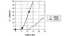
- the pressure applied to the microporous membranes of Example 1 and Comparative Example 1 and the change rate of the Gurley value are shown.
- the polyolefin microporous membrane according to one aspect of the present invention includes a process of using a restraining member that suppresses expansion / contraction from the outside of the device, such as a power storage device for automobile use, or compressing the device. Also in the separator for an electricity storage device, superior durability in the thickness direction is exhibited. As a result, it has been found that the characteristics of the electricity storage device can be maintained by using the polyolefin microporous membrane according to one embodiment of the present invention as a separator.
- the present invention will be described below as an example, but the contents of the present invention are not limited to the following contents.
- separators used for power storage devices such as lithium ion secondary batteries and lithium ion capacitors will be described.
- the shape of the separator may be appropriately adjusted according to, for example, the shape of the lithium ion secondary battery.
- the shapes of the positive electrode and the negative electrode may be appropriately adjusted according to the shape of the lithium ion secondary battery.
- the separator is composed of, for example, a polyolefin microporous film and has a single layer structure or a multilayer structure.
- the separator may be composed of only a resin layer made of polyolefin, but may be provided with a resin layer made of polyolefin and a porous heat-resistant layer formed on the surface of the resin layer.
- the separator may further include an adhesive layer.
- the heat-resistant layer can be expected to suppress the thermal contraction of the resin layer and to enhance the function of preventing the internal short circuit of the battery due to the film breakage of the resin layer.
- the heat-resistant layer may be provided only on one side of the resin layer, or may be provided on both sides.
- the resin material for the polyolefin microporous membrane for example, a polyolefin-based resin such as PE (polyethylene) or PP (polypropylene) can be used.
- the structure of the resin layer may be a single layer structure or a multilayer structure.
- the multilayer structure includes a three-layer structure including a PP layer, a PE layer laminated on the PP layer, and a PP layer laminated on the PE layer.
- the number of layers in the multilayer structure is not limited to three, and may be two or four or more.
- a uniaxially stretched or biaxially stretched polyolefin microporous film can be suitably used as the separator.
- a polyolefin microporous film uniaxially stretched in the longitudinal direction (MD direction) is particularly preferable because it has an appropriate strength and has little heat shrinkage in the width direction.
- MD direction a polyolefin microporous membrane
- thermal shrinkage in the longitudinal direction can be suppressed when wound together with a long sheet-like positive electrode and negative electrode.
- the polyolefin microporous film uniaxially stretched in the longitudinal direction is particularly suitable as a separator constituting a wound electrode body.
- the thickness of the polyolefin microporous membrane is not particularly limited.
- the thickness of the polyolefin microporous membrane is preferably about 8 ⁇ m to 40 ⁇ m, for example.
- the ionic conductivity tends to decrease.
- the thickness of the polyolefin microporous film is too thin, there is a tendency that membrane breakage tends to occur.
- the thickness of the polyolefin microporous film can be determined by image analysis of an image obtained by photographing a cross section of the microporous film with a scanning electron microscope (SEM), or by a dot-type thickness measuring device.
- SEM scanning electron microscope
- the polyolefin microporous membrane according to one embodiment of the present invention is produced by, for example, passing through three steps of a raw fabric production process, a lamination process, and a stretching process.
- the polypropylene and polyethylene constituting each layer may have the same or different molecular weight in each layer. Polypropylene having high stereoregularity is preferable.
- the polyethylene is more preferably high density polyethylene having a density of 0.960 or more. Medium density polyethylene can also be used for polyethylene.
- These polypropylene and polyethylene may contain additives such as surfactants, anti-aging agents, plasticizers, flame retardants, and colorants.
- the raw film for producing the separator has only to have the property of having a uniform thickness and making it porous by stretching after laminating a plurality of raw film.
- multiple types of raw film are prepared.
- melt molding using a T die is suitable.
- an inflation method, a wet solution method, or the like can also be employed.
- melt-molding a raw film with a T-die it is generally performed at a temperature 20 to 60 ° C. higher than the melting temperature of the resin. In this case, the draft ratio is preferably set to 10 to 1000, and more preferably 50 to 500.
- the take-up speed of the raw film is not particularly limited, but is 10 to 200 m / min. It is common to be molded with. Since the take-up speed affects the final properties of the microporous polyolefin membrane (birefringence and elastic recovery rate include the pore size, porosity, delamination strength, and mechanical strength of the microporous polyolefin membrane after stretching). One of the important elements. Moreover, in order to keep the surface roughness of the polyolefin microporous film below a certain value, the uniformity of the thickness of the raw film is important. The coefficient of variation (CV) with respect to the thickness of the original fabric is preferably adjusted to a range of 0.001 to 0.030.
- fine particles may be mixed in the resin layer that is the outer layer of the original film (multilayer film).
- the fine particles function as a lubricant for the raw film.
- the fine particles are preferably mixed in an amount that does not affect the surface roughness of the raw film and the surface roughness of the porous film after the stretching step.
- the fine particles it is preferable to use particles made of an inorganic insulator (hereinafter simply referred to as “inorganic insulator particles”).
- the inorganic insulator particles are an inorganic material having electrical insulating properties.
- the inorganic insulator particles mixed in the resin layer preferably have an oxidation potential of +4.5 V or more with respect to lithium.
- the oxidation potential is sufficiently high, the reliability and safety when a polyolefin microporous membrane containing inorganic insulator particles is used as a separator for a lithium ion secondary battery is increased.
- the electrochemical stability of the lithium ion secondary battery is increased. From this viewpoint, the oxidation potential of the inorganic insulator particles is more preferably +5.0 V or more with respect to lithium.
- oxides, hydroxides, inorganic nitrides, sparingly soluble ionic crystals, covalent bonds, clays and the like can be used.
- oxide and hydroxide include those containing as a main component one or more inorganic elements selected from the group consisting of Si, Al, Ti, Mg, Zn, Na, Ca, and Li.
- the inorganic nitride include aluminum nitride and silicon nitride.
- the hardly soluble ionic crystals include calcium fluoride, barium fluoride, and barium sulfate.
- covalent bond crystal include silicon and diamond.
- clay include montmorillonite.
- the oxide containing a specific element as a main component preferably has a mass ratio of the specific element of 50% by mass or more in terms of the oxide.
- the oxide include single element oxides such as silica (SiO 2 ), alumina (Al 2 O 3 ), TiO 2 , magnesia, and zinc oxide.
- the oxide (composite oxide) of two or more kinds of inorganic elements include aluminosilicate and MgAl 2 O 4 .
- the aluminosilicate is represented by x1M1 2 O.x2M2O.yAl 2 O 3 .zSiO 2 .nH 2 O.
- M1 is one or more selected from Na and Li
- M2 is one or more selected from Ca
- x1 and x2 are each independently a number of 0 or more and 2.0 or less
- y Is a number of 0.5 or more and 2.0 or less
- z is a number of 1.0 or more and 5.0 or less
- n is a number of 0 or more.
- the inorganic metal hydroxide include aluminum hydroxide.
- the oxide or hydroxide of an inorganic element includes a mineral resource-derived material or an artificial product thereof.
- An inorganic insulator can also be used combining 1 type (s) or 2 or more types of inorganic insulators. Any of the above-described inorganic insulator particles can be used, but composite oxides such as aluminosilicate are particularly preferable.
- the average particle diameter D of the inorganic insulator particles is preferably 0.1 ⁇ m or more and 10 ⁇ m or less, more preferably 0.5 ⁇ m or more and 5 ⁇ m or less, and further preferably 1 ⁇ m or more and 3 ⁇ m or less.
- the amount of inorganic insulator particles added is, for example, preferably about 500 to 8000 ppm, more preferably 1000 to 6000 ppm, and further preferably 2500 to 5000 ppm in terms of the weight ratio to the resin layer to be added.
- [Lamination process] It describes about the process of laminating
- the polypropylene film and the polyethylene film are laminated by thermocompression bonding.
- Lamination of a plurality of films is performed by thermocompression bonding by passing a laminated film between heated rolls. Specifically, each film is unwound from a plurality of sets of raw roll stands, laminated, and nipped between heated rolls, whereby each film is pressure-bonded and laminated. At the time of lamination, it is necessary to perform thermocompression bonding so that the birefringence and the elastic recovery rate of each film are not substantially lowered.
- the layer configuration is not limited in the case of a three-layer configuration or a two-layer configuration.
- a three-layer structure for example, a structure in which the front and back of the three layers are polypropylene and the center is polyethylene, that is, the outer layer is polypropylene and the inner layer is polyethylene (PP / PE / PP), outer layer And (PE / PP / PP) structure in which the inner layer is made of polypropylene.
- PP / PE polypropylene and polyethylene are bonded together.
- the layer structure is not limited, but a three-layer structure (PP / PE / PP) in which the outer layer is polypropylene and the inner layer is polyethylene is most suitable. This configuration is less curled and less susceptible to trauma. Further, the polyolefin microporous membrane having this configuration is excellent in heat resistance, mechanical strength, and the like. Furthermore, characteristics such as safety and reliability when the polyolefin microporous film having this configuration is used as a separator for an electricity storage device are also satisfied.
- the temperature of the heated roll (thermocompression bonding temperature) for thermocompression bonding the multiple layers of the raw film is preferably 120 to 160 ° C, and more preferably 125 to 150 ° C. If the temperature is too low, the peel strength between the films is weak, and peeling occurs in the subsequent stretching step. On the other hand, if it is too high, the polyethylene melts and the birefringence and elastic recovery of the film are greatly reduced.
- the peel strength of the polyolefin microporous membrane is preferably in the range of 3 to 90 g / 15 mm.
- the thickness of the laminated film is not particularly limited, but generally 10 to 60 ⁇ m is appropriate.
- each layer of PP and PE is simultaneously made porous in the stretching process.
- the stretching step is performed by four zones: a heat treatment zone (oven 1), a cold stretching zone, a hot stretching zone (oven 2), and a heat setting zone (oven 3).
- the laminated film is heat treated in a heat treatment zone before being stretched.
- the heat treatment is performed by a heated air circulation oven or a heating roll.
- the heat treatment of the laminated film is performed under a tension in which the laminated film is stretched so as not to increase the fixed length or the length by 10% or more.
- the heat treatment temperature is preferably in the range of 110 to 150 ° C., more preferably in the range of 115 to 140 ° C. When the temperature is low, the film is not sufficiently porous, and when it is too high, the polyethylene is melted.
- the heat treatment time may be about 3 seconds to 3 minutes.
- the heat-treated laminated film is stretched in the cold stretching zone. Then, it passes through a heat
- Polypropylene and polyethylene are not easily made porous by only one of the stretching, and the characteristics when a laminated porous film (polyolefin microporous film) is used as a battery separator deteriorates.
- the temperature in the cold drawing zone is preferably from minus 20 ° C. to plus 50 ° C., more preferably from 20 to 40 ° C. If the stretching temperature is too low, the film tends to break during the operation. On the other hand, if the stretching temperature is too high, the porosity becomes insufficient.
- the low-temperature stretching ratio is preferably in the range of 3 to 200%, more preferably in the range of 5 to 100%. If the low-temperature stretching ratio is too low, only those with a low porosity can be obtained, and if the low-temperature stretching ratio is too high, a product with a predetermined porosity and pore diameter cannot be obtained.
- the laminated film which has been stretched at a low temperature is stretched at a high temperature in a heat stretching zone.
- the temperature of the high temperature stretching is preferably 70 to 150 ° C, more preferably 80 to 145 ° C. Outside this range, it is difficult to achieve sufficient porosity.
- the ratio of high temperature stretching is in the range of 100 to 400%. If the maximum draw ratio is too low, the gas permeability of the laminated porous film (polyolefin microporous film) will be low, and if the maximum draw ratio is too high, the gas permeability of the laminated porous film (polyolefin microporous film) will be high. Too much.
- Thermothermal relaxation is a step in which heat shrinkage is performed in advance to such an extent that the film length after stretching is reduced by 10 to 300% in order to prevent shrinkage in the stretching direction of the film due to residual stress acting during stretching.
- the temperature during thermal relaxation is preferably 70 to 145 ° C, more preferably 80 to 140 ° C.
- the temperature at the time of thermal relaxation is too high, the PE layer melts and is difficult to use as a separator.
- thermal relaxation when the temperature at the time of thermal relaxation is too low, thermal relaxation is not sufficient, and the thermal contraction rate when used as a separator increases. That is, the thermal contraction rate of the product is increased, which is not preferable as a separator for an electricity storage device.
- the heat-treated film that has passed through the heat-stretching zone is subjected to a heat treatment in the heat-fixing zone so that the dimensions in the heat-stretching direction do not change.
- the heat setting is performed by a heated air circulation oven or a heating roll. Also in this case, the heat treatment film is stretched under a constant length or under a tension that prevents the length from increasing by 10% or more.
- the heat setting temperature is preferably in the range of 110 to 150 ° C, more preferably in the range of 115 to 140 ° C. When the heat setting temperature is low, a sufficient heat setting effect cannot be obtained and the heat shrinkage rate is increased. On the other hand, if the heat setting temperature is too high, melting of polyethylene occurs, which is inconvenient.
- the polyolefin microporous membrane according to one aspect of the present invention is a raw film that is excellent in thickness accuracy at the time of forming the raw film, laminated, and stretched and heat-set after heat shrinkage. It is obtained by doing. Therefore, the polyolefin microporous membrane has excellent compression characteristics, good dimensional stability, and high delamination strength that can satisfy the intended problem.
- the method for producing a polyolefin microporous membrane is not only the above-mentioned process in which a plurality of raw films are separately formed and laminated together, but also the resin extruded from individual extruders is joined in a die. It is also possible to use a method of extruding together.
- a high polyolefin microporous membrane can be obtained.
- the polyolefin microporous membrane made from a raw film mixed with fine particles improves slipperiness with the parts of a metal winding machine, which is the central axis, especially when manufacturing a wound battery. ing. Therefore, the yield in the battery manufacturing process can be improved.
- a heat-resistant coating layer by the method of mixing an inorganic particle and a binder and passing through a coating process on the single side
- a bonding layer may be applied by applying a fluorine resin.
- the heat resistant coating film can be obtained by, for example, a known method described in Patent Document 7.
- the porosity of the polyolefin microporous membrane according to one embodiment of the present invention used as a separator for an electricity storage device is preferably 30 to 80%, and more preferably 35 to 60%.
- the maximum pore size of the polyolefin microporous membrane is preferably 0.02 to 2 ⁇ m, more preferably 0.08 to 0.5 ⁇ m.
- the porosity and maximum efficiency vary somewhat depending on the choice of manufacturing conditions. If the porosity is too low, the function when used as a battery separator cannot be obtained sufficiently. On the other hand, if the porosity is too large, the mechanical strength when used as a battery separator is deteriorated.
- the Gurley value of the polyolefin microporous membrane according to one embodiment of the present invention is preferably 80 to 1500 seconds / 100 cc, and more preferably 100 to 800 seconds / 100 cc.
- the delamination strength of the polyolefin microporous membrane is preferably 3 to 80 g / 15 mm. When the delamination strength is low, for example, in the manufacturing process of a battery separator, film peeling, curling, elongation, etc. are likely to occur, which may cause problems in product quality.
- the total thickness of the polyolefin microporous membrane is suitably 5 to 40 ⁇ m from the viewpoint of mechanical strength, performance, miniaturization, etc. as a separator for an electricity storage device.
- the heat resistant porous layer contains a filler (filler) and a binder.
- the heat-resistant porous membrane is layered on the polyolefin microporous membrane.
- the heat-resistant porous layer is obtained by preparing a slurry for forming a heat-resistant porous layer by mixing a filler, a binder, and a solvent, and applying the slurry on a polyolefin microporous film and drying it.
- particles selected from at least one of an inorganic material, an inorganic oxide, or an inorganic hydroxide having a high electrical insulation and a melting point higher than those of the polyethylene layer and the polypropylene layer can be used.
- an inorganic material an inorganic oxide, or an inorganic hydroxide having a high electrical insulation and a melting point higher than those of the polyethylene layer and the polypropylene layer
- particles selected from at least one of an inorganic material, an inorganic oxide, or an inorganic hydroxide having a high electrical insulation and a melting point higher than those of the polyethylene layer and the polypropylene layer can be used.
- particles selected from at least one of an inorganic material, an inorganic oxide, or an inorganic hydroxide having a high electrical insulation and a melting point higher than those of the polyethylene layer and the polypropylene layer can be used.
- ⁇ Filler shape is not particularly limited.
- particulates, fibers, flakes, etc. can be used, and particulate fillers are suitable.
- the average particle size of the filler can be, for example, about 0.1 ⁇ m to 2.5 ⁇ m, preferably 0.2 ⁇ m to 1.0 ⁇ m, and more preferably 0.3 ⁇ m to 0.8 ⁇ m.
- the binder includes, for example, a polymer of N-vinylacetamide, an acrylic resin (for example, a polymer having an acrylic ester polymer as a main component), a styrene-butadiene rubber (SBR), a polyolefin resin such as PE and PP, Cellulose resins such as carboxymethylcellulose (CMC), fluorine resins such as polyvinylidene fluoride (PVDF), and the like can be used. These may be used alone or in combination of two or more.
- an acrylic resin for example, a polymer having an acrylic ester polymer as a main component
- SBR styrene-butadiene rubber
- PE and PP polyolefin resin
- CMC carboxymethylcellulose
- PVDF polyvinylidene fluoride
- the form of the binder is not particularly limited.
- a particulate material may be used, or a solution prepared in the form of a solution may be used.
- the particle size of the binder is not particularly limited, and for example, a binder having an average particle size of about 0.05 ⁇ m to 0.5 ⁇ m may be used.
- the resin binder content in the heat resistant porous layer may be 1.1 to 30 parts by mass with respect to 100 parts by mass of the heat resistant fine particles.
- Examples of the method for applying the slurry to the polyolefin microporous film include a die coater, a gravure roll coater, a reverse roll coater, a kiss roll coater, a dip roll coater, a bar coater, an air knife coater, a spray coater, a brush coater, and a screen coater. It can apply
- drying conditions after applying the slurry for example, a method of drying by holding at a temperature lower than the melting point of the PE layer (for example, about 70 ° C. to 130 ° C.) or a method of drying by holding at a low temperature under reduced pressure, etc. Is mentioned.
- the thickness of the heat-resistant porous layer after drying is preferably about 1 ⁇ m to 15 ⁇ m, more preferably about 1.5 ⁇ m to 10 ⁇ m, and still more preferably 2.0 to 8.0 ⁇ m. If the heat-resistant porous layer is too thick, the handleability and workability of the separator may decrease, and defects such as cracks and peeling may easily occur. If the heat-resistant porous layer is too thin, the effect of preventing the short-circuit of the heat-resistant porous layer may be weakened, and problems such as deterioration of the electrolyte retention characteristics may occur. When the thickness of the heat resistant coating layer is 1 ⁇ m or less, the required heat resistance cannot be obtained.
- the peel strength between the polyolefin microporous membrane and the heat-resistant porous layer is not particularly limited, but those having high peel strength are preferred.
- Non-aqueous electrolyte Preferred examples of the non-aqueous solvent used in the non-aqueous electrolyte include cyclic carbonates and chain esters. In order to synergistically improve electrochemical properties in a wide temperature range, particularly at high temperatures, it is preferable that a chain ester is included, more preferably a chain carbonate is included, and both a cyclic carbonate and a chain carbonate are included. Most preferably.
- the term “chain ester” is used as a concept including a chain carbonate and a chain carboxylic acid ester.
- cyclic carbonate examples include one or more selected from ethylene carbonate (EC), propylene carbonate (PC), and vinylene carbonate (VC), and a combination of EC and VC and a combination of PC and VC are particularly preferable.
- EC ethylene carbonate
- PC propylene carbonate
- VC vinylene carbonate
- the non-aqueous solvent contains ethylene carbonate and / or propylene carbonate
- the stability of the film formed on the electrode increases, and the high temperature and high voltage cycle characteristics are improved.
- the content of ethylene carbonate and / or propylene carbonate is preferably 3% by volume or more, more preferably 5% by volume or more, and still more preferably 7% by volume or more with respect to the total volume of the nonaqueous solvent.
- the upper limit is preferably 45% by volume or less, more preferably 35% by volume or less, and still more preferably 25% by volume or less.
- chain ester methyl ethyl carbonate (MEC) as an asymmetric chain carbonate, dimethyl carbonate (DMC), diethyl carbonate (DEC) as a symmetric chain carbonate, ethyl acetate (hereinafter referred to as EA) as a chain carboxylate ester
- DMC dimethyl carbonate
- DEC diethyl carbonate
- EA ethyl acetate
- chain esters combinations of asymmetric and ethoxy group-containing chain esters such as MEC and EA are possible.
- the content of the chain ester is not particularly limited.
- the chain ester content is preferably in the range of 60 to 90% by volume with respect to the total volume of the non-aqueous solvent. If the content is 60% by volume or more, the viscosity of the non-aqueous electrolyte does not become too high, and if it is 90% by volume or less, the electrical conductivity of the non-aqueous electrolyte is lowered and the temperature is wide, particularly at high temperatures. The risk of degradation of electrochemical properties is reduced.
- the proportion of the volume occupied by EA in the chain ester is preferably 1% by volume or more in the non-aqueous solvent, and more preferably 2% by volume or more.
- the upper limit is more preferably 10% by volume or less, and even more preferably 7% by volume or less.
- the asymmetric chain carbonate preferably has an ethyl group, and is particularly preferably methyl ethyl carbonate.
- the ratio between the cyclic carbonate and the chain ester is preferably 10:90 to 45:55 in terms of the cyclic carbonate: chain ester (volume ratio) from the viewpoint of improving electrochemical characteristics over a wide temperature range, particularly at high temperatures, and 15:85. ⁇ 40: 60 is more preferred, and 20:80 to 35:65 is particularly preferred.
- a preferable example of the electrolyte salt is a lithium salt.
- the lithium salt is preferably one or more selected from the group consisting of LiPF 6 , LiBF 4 , LiN (SO 2 F) 2 , LiN (SO 2 CF 3 ) 2 , and LiPF 6 , LiBF 4 and LiN ( One or more selected from SO 2 F) 2 is more preferred, and LiPF 6 is most preferred.
- the non-aqueous electrolyte can be obtained, for example, by a method of mixing a non-aqueous solvent and adding a composition obtained by mixing an electrolyte salt and a dissolution aid to the non-aqueous electrolyte in a specific mixing ratio.
- the compound added to the non-aqueous solvent and the non-aqueous electrolyte to be used is one that is purified in advance and has as few impurities as possible within a range that does not significantly reduce the productivity.
- the polyolefin microporous membrane according to one embodiment of the present invention can be used in the following first and second electricity storage devices, and not only a liquid but also a gelled nonaqueous electrolyte can be used. .
- the polyolefin microporous membrane according to one embodiment of the present invention is used as a separator for a lithium ion battery (first power storage device) or a lithium ion capacitor (second power storage device) that uses a lithium salt as an electrolyte salt.
- it is more preferably used for a lithium ion battery, and more preferably used for a lithium ion secondary battery.
- a lithium ion secondary battery includes the nonaqueous electrolytic solution in which an electrolyte salt is dissolved in a positive electrode, a negative electrode, and a nonaqueous solvent.
- Components other than the non-aqueous electrolyte, such as a positive electrode and a negative electrode, can be used without particular limitation.
- the positive electrode active material for a lithium ion secondary battery a composite metal oxide with lithium containing one or more selected from the group consisting of cobalt, manganese, and nickel is used. These positive electrode active materials can be used alone or in combination of two or more.
- lithium composite metal oxide examples include LiCoO 2 , LiCo 1-x M x O 2 (where M is Sn, Mg, Fe, Ti, Al, Zr, Cr, V, Ga, Zn, and 1 or 2 or more elements selected from Cu), LiMn 2 O 4 , LiNiO 2 , LiCo 1-x Ni x O 2 , LiCo 1/3 Ni 1/3 Mn 1/3 O 2 , LiNi 0.5 Mn 0.3 Co 0.2 Mn 0.3 O 2 , LiNi 0.8 Mn 0.1 Co 0.1 O 2 , LiNi 0.8 Co 0.15 Al 0.05 O 2 , Li 2 MnO 3 and Preferable examples include one or more selected from a solid solution with LiMO 2 (M is a transition metal such as Co, Ni, Mn, and Fe) and LiNi 1/2 Mn 3/2 O 4 .
- M is Sn, Mg, Fe, Ti, Al, Zr, Cr, V, Ga, Zn, and 1 or 2 or more elements selected from Cu
- LiMn 2 O 4 LiN
- the positive electrode conductive agent is not particularly limited as long as it is an electron conductive material that does not cause a chemical change.
- Examples thereof include one or two or more carbon blacks selected from natural graphite (such as flake graphite), graphite such as artificial graphite, and acetylene black.
- the positive electrode active material is a conductive agent such as acetylene black or carbon black, polytetrafluoroethylene (PTFE), polyvinylidene fluoride (PVDF), a copolymer of styrene and butadiene (SBR), a copolymer of acrylonitrile and butadiene. It is mixed with a binder such as a polymer (NBR) or carboxymethyl cellulose (CMC). A solvent is added to this mixture and kneaded to obtain a positive electrode mixture. The obtained positive electrode mixture is applied to an aluminum foil or a stainless steel plate as a current collector, dried, pressure-molded, and heat-treated under predetermined conditions.
- PTFE polytetrafluoroethylene
- PVDF polyvinylidene fluoride
- SBR styrene and butadiene
- acrylonitrile and butadiene acrylonitrile and butadiene.
- NBR polymer
- CMC carboxymethyl
- Examples of the negative electrode active material for a lithium ion secondary battery include lithium metal and lithium alloy, and a carbon material capable of inserting and extracting lithium, tin (single), tin compound, silicon (single), silicon compound, or Li
- a lithium titanate compound such as 4Ti 5 O 12 can be used alone or in combination of two or more.
- artificial graphite particles having a massive structure in which a plurality of flat graphite fine particles are assembled or bonded non-parallel to each other, and mechanical actions such as compressive force, frictional force, shearing force, etc. are repeatedly applied, and scaly natural graphite is spherical. It is preferable to use particles that have been treated.
- the negative electrode is obtained by the same procedure as the above positive electrode.
- a negative electrode mixture is obtained by kneading using the same conductive agent, binder, and high-boiling solvent as in the production of the positive electrode.
- the obtained negative electrode mixture is applied to a copper foil or the like of a current collector, dried and pressure-molded, and then heat-treated under predetermined conditions.
- Lithium ion secondary battery There is no particular limitation on the structure of the lithium ion secondary battery which is one of the electricity storage devices according to one embodiment of the present invention.
- a coin-type battery, a cylindrical battery, a square battery, a laminate battery, or the like can be applied.
- the wound lithium ion secondary battery has, for example, a configuration in which an electrode body is housed in a battery case together with a non-aqueous electrolyte.
- the electrode body includes a positive electrode, a negative electrode, and a separator. At least a part of the non-aqueous electrolyte is impregnated in the electrode body.
- a positive electrode in a wound lithium ion secondary battery, includes a long sheet-shaped positive electrode current collector and a positive electrode mixture layer including a positive electrode active material and provided on the positive electrode current collector.
- the negative electrode includes a long sheet-shaped negative electrode current collector and a negative electrode mixture layer that includes a negative electrode active material and is provided on the negative electrode current collector.
- the separator is formed into a long sheet like the positive electrode and the negative electrode.
- the positive electrode and the negative electrode are wound in a cylindrical shape with a separator interposed therebetween.
- the shape of the electrode body after winding is not limited to a cylindrical shape. For example, after winding the positive electrode, the separator, and the negative electrode, a flat shape may be formed by applying pressure from the side.
- the battery case includes a bottomed cylindrical case body and a lid that closes the opening of the case body.
- the lid and the case main body are made of metal, for example, and are insulated from each other.
- the lid is electrically connected to the positive electrode current collector, and the case body is electrically connected to the negative electrode current collector. You may make it a lid
- the lithium ion secondary battery can be charged and discharged at ⁇ 40 to 100 ° C., preferably ⁇ 10 to 80 ° C.
- a countermeasure against a rise in the internal pressure of the wound lithium ion secondary battery a countermeasure for providing a safety valve on the battery lid or a countermeasure for cutting a member such as a battery case main body or a gasket can be employed.
- a current interruption mechanism that senses the internal pressure of the battery and interrupts the current can be provided on the lid.
- a positive electrode, a negative electrode, and a separator are prepared. Next, they are overlapped and wound into a cylindrical shape to assemble an electrode body. Next, the electrode body is inserted into the case body, and a non-aqueous electrolyte is injected into the case body. Thereby, the non-aqueous electrolyte is impregnated in the electrode body. After injecting the non-aqueous electrolyte into the case body, the case body is covered with a lid, and the lid and the case body are sealed.
- the shape of the electrode body after winding is not limited to a cylindrical shape. For example, after winding the positive electrode, the separator, and the negative electrode, a flat shape may be formed by applying pressure from the side.
- the present invention is not limited to this and may be applied to a laminated type lithium ion secondary battery.
- the positive electrode or the negative electrode may be sandwiched and packaged by a pair of separators.
- the electrode is a packaged electrode.
- the separator has a size slightly larger than the electrode. While sandwiching the main body of the electrode between the pair of separators, the tab protruding from the end of the electrode is projected outward from the separator. Bonding the side edges of a pair of stacked separators to form a bag, and alternately laminating one electrode and the other electrode packed in this separator and impregnating the electrolyte solution to produce a laminated battery To do. At this time, in order to reduce the thickness, the separator and the electrode may be compressed in the thickness direction.
- the above lithium ion secondary battery can be used as a secondary battery for various applications.
- it can be suitably used as a power source for a drive source such as a motor that is mounted on a vehicle such as an automobile and drives the vehicle.
- a drive source such as a motor that is mounted on a vehicle such as an automobile and drives the vehicle.
- a vehicle such as an automobile and drives the vehicle.
- the kind of vehicle is not specifically limited, For example, a hybrid vehicle, a plug-in hybrid vehicle, an electric vehicle, a fuel cell vehicle etc. are mention
- Such a lithium ion secondary battery may be used alone, or may be used by connecting a plurality of batteries in series and / or in parallel.
- the lithium ion capacitor has a polyolefin microporous membrane according to one embodiment of the present invention, a non-aqueous electrolyte, a positive electrode, and a negative electrode, and uses energy of lithium ion intercalation into a carbon material such as graphite as a negative electrode.
- a positive electrode for example, a positive electrode using an electric double layer between an activated carbon electrode and an electrolytic solution, a negative electrode using a ⁇ -conjugated polymer electrode dope / dedope reaction, or the like is used.
- the electrolytic solution contains at least a lithium salt such as LiPF 6 .
- Measurements were performed according to ASTM D-822. Three strip-shaped test pieces having a width of 10 mm and a length of 100 mm were sampled from the width direction (TD) and the length direction (MD), respectively, at the center and left and right ends (10 mm inside from the end face).
- the tensile strength was calculated from the following equation from the load W (kg) when the test piece was broken and the cross-sectional area S of the test piece (mm 2 , and the thickness used the average value of thickness measurement).
- the tensile elongation was calculated from the following formula from the distance L 0 (mm) between the gauge points of the test piece before the test and the gauge distance L (mm) at break.
- the tensile strength in the MD direction was rounded to the first decimal place by rounding off the second decimal place.
- the tensile strength in the TD direction was rounded to the second decimal place by rounding off the third decimal place.
- Tensile elongation was rounded to the nearest whole number, rounded to the first decimal place. The average value of each measured value was evaluated as tensile strength and tensile elongation.
- the weight per unit area was calculated from the following formula. The result was rounded to the second decimal place by rounding off the third decimal place, and the average of the two points was obtained.
- a test piece (200 ⁇ 200 mm) was taken from the inside of the sample 10 mm on both sides.
- a gage with a distance between gage points of 180 mm was written in the center of each test piece in each of the width direction (TD) and the length direction (MD), and the distance between gage points was measured with a steel rule.
- a sample in which the dimension between the marked lines was entered was sandwiched between papers, and heat treatment was performed at 105 ° C. for 2 hours using Yamato Kagaku's hot air circulation model: DK-43.
- the heat-treated sample was taken out while being sandwiched between papers, allowed to cool at room temperature for 60 minutes, and the distance between the gauge points was measured with a steel rule.
- the heat shrinkage rate was calculated by the following formula, assuming that the length between marked lines before heating was L1 (mm) and the length between marked lines after heating was L2 (mm).
- the stress when a load of 100 N is applied to a 10 mm ⁇ metal column is 100 N / (5 mm ⁇ 5 mm ⁇ ⁇ ) ⁇ 1.27 MPa.
- the maximum pore size of the microporous polyolefin membrane is in the range of 0.15 g sample weight and 0.0065-10 ⁇ m pore diameter using a fully automatic pore distribution measuring device (PoreMaster 60-GT type) manufactured by Cantachrome Instruments. From these measurement results, the maximum pore diameter was calculated and used for evaluation.
- Example 1 an example of a method for producing the polyolefin microporous membrane of the present example will be described, but the production method is not limited to the following, and other methods may be used.
- a polyolefin microporous film may be produced by a co-extrusion step using a T die and a stretching step.
- PP film formation Using a T die with a discharge width of 1000 mm and a discharge lip opening of 2 mm, a polypropylene resin having a weight average molecular weight of 470,000, a molecular weight distribution of 6.7, a pentad fraction of 94%, and a melting point of 161 ° C. is used. Melt extrusion was performed at 200 ° C. The discharged film was guided to a cooling roll at 90 ° C., cooled by blowing cold air at 37.2 ° C., and then 40 m / min. I picked it up.
- the film thickness of the obtained unstretched polypropylene film was 8.1 ⁇ m, the birefringence was 16.1 ⁇ 10 ⁇ 3 , and the elastic recovery ratio was 88% after heat treatment at 150 ° C. for 30 minutes.
- the coefficient of variation (CV) with respect to the thickness of the original film of the obtained original film was 0.015.
- the film thickness of the obtained unstretched polyethylene film was 9.4 ⁇ m, the birefringence was 36.7 ⁇ 10 ⁇ 3 , and the elastic recovery rate at 50% elongation was 39%.
- the coefficient of variation (CV) with respect to the thickness of the original film of the obtained original film was 0.016.
- the three-layer laminated film was introduced into a hot air circulation oven (heat treatment zone: oven 1) heated to 125 ° C. and subjected to heat treatment.
- the heat-treated laminated film was then stretched at a low temperature of 18% (initial stretching ratio) between nip rolls maintained at 35 ° C. in a cold stretching zone.
- the roll speed on the supply side is 2.8 m / min. Met.
- the hot stretching zone (oven 2) heated to 130 ° C., the rolls were hot stretched to 190% (maximum stretch ratio) between the rollers using the difference in the peripheral speed of the roll.
- the film was thermally relaxed to 125% (final draw ratio), and then heat-set at 133 ° C. in a heat-setting zone (oven 3) to continuously obtain a polyolefin microporous film.
- Compressive elastic modulus of the obtained microporous polyolefin membrane is Compressive elastic modulus of the obtained microporous polyolefin membrane, strain amount at 2.7 MPa pressurization, film thickness, Gurley value, tensile strength, tensile elongation, heat shrinkage rate, porosity (weight method), puncture strength
- Table 1 shows the measurement results of weight per unit area, surface roughness, shutdown temperature, meltdown temperature, and maximum pore diameter. The polyolefin microporous membrane had no curl and no pinhole was observed.
- Example 1 A microporous film of a polyethylene single layer was produced by a wet method using a known method. The film thickness of the obtained microporous film was 19.7 ⁇ m. Table 1 shows the measurement results such as physical properties.
- Example 2 [Production of lithium ion secondary battery] 94% by mass of LiNi 1/3 Mn 1/3 Co 1/3 O 2 and 3% by mass of acetylene black (conductive agent) were mixed. The mixture was added to a previously prepared solution of 3% by mass of polyvinylidene fluoride (binder) dissolved in 1-methyl-2-pyrrolidone and mixed to prepare a positive electrode mixture paste. This positive electrode mixture paste was applied to one side of an aluminum foil (current collector), dried and pressurized, and cut into a predetermined size to produce a belt-like positive electrode sheet. The density of the portion excluding the current collector of the positive electrode was 3.6 g / cm 3 .
- the positive electrode sheet, the polyolefin microporous membrane of Example 1, and the negative electrode sheet were laminated in this order, and a non-aqueous electrolyte was added to produce a laminate type battery.
- Example 2 changes in the resistance in the battery were monitored by applying pressures with different strengths to the dry polyolefin microporous membrane having a three-layer structure of PP / PE / PP.
- Comparative Example 2 a DC-R test was performed using a polyolefin microporous membrane having a single layer structure (Comparative Example 1) made of PE manufactured by a wet method.
- the change in the resistance in the battery was monitored in the same manner as in Example 2 except that a wet PE single-layer polyolefin microporous membrane was used as the polyolefin microporous membrane.
- Table 6 The results are shown in Table 6.
- Example 3 It was prepared in the same manner as in Example 1 except that the film thickness of the PP original fabric was 6.2 ⁇ m and the film thickness of the PE original fabric was 8.0 ⁇ m. C. of the obtained PP original fabric. V. Is 0.020, and the C.E. V. Was 0.018. The film thickness of the microporous film prepared using these original fabrics was 16.3 ⁇ m. Other physical property values are shown in Table 1.
- Example 4 It was prepared in the same manner as in Example 1 except that the film thickness of the PP original fabric was 10.8 ⁇ m and the film thickness of the PE original fabric was 9.4 ⁇ m. C. of the obtained PP original fabric. V. Is 0.012, and the C.I. V. Was 0.016. The film thickness of the microporous membrane prepared using these original fabrics was 25.0 ⁇ m. Other physical property values are shown in Table 1.
- Example 5 It was prepared in the same manner as in Example 1 except that the film thickness of the PP original fabric was 14.4 ⁇ m and the film thickness of the PE original fabric was 7.6 ⁇ m. C. of the obtained PP original fabric. V. Is 0.009 and the C.E. V. Was 0.022. The film thickness of the microporous membrane prepared using these original fabrics was 30.1 ⁇ m. Other physical property values are shown in Table 1.
- Example 6 The film thickness of the PP original fabric was 40.0 ⁇ m, and the single film of the PP layer was stretched in the same manner as in the stretching process of Example 1 to produce a porous film. C. of the obtained PP original fabric. V. was 0.010. The film thickness of the microporous membrane prepared using these original fabrics was 32.2 ⁇ m. Other physical property values are shown in Table 1.
- Example 7 Three layers of PP / PE / PP were bonded together in a T-die in the molten state, and both were extruded from the die to form a raw material with PP / PE / PP laminated.
- the thickness of the original fabric is 14.8 ⁇ m.
- V. was 0.015.
- the laminated original fabric was processed in the same stretching process as in Example 1 to produce a microporous film having a thickness of 12.5 ⁇ m.
- Table 2 shows the physical properties of the prepared microporous membrane.
- Example 8 A microporous film having a three-layer structure of PP / PE / PP was prepared in the same manner as in Example 7 except that the film thickness of the original fabric was 19.2 ⁇ m. The film thickness of the microporous film was 16.3 ⁇ m. Table 2 shows the measurement results such as physical properties.
- Example 9 A microporous film having a thickness of 24.9 ⁇ m was prepared by coating and drying a heat-resistant coating layer having a thickness of about 5 ⁇ m on the microporous film of Example 1.
- Table 2 shows the physical properties of the prepared microporous membrane.
- a slurry was prepared using boehmite as a filler to form a heat resistant porous layer.
- Example 10 Example 1 except that aluminosilicate (average particle size 2 ⁇ m) was added to the PP resin as inorganic insulator particles so as to have a weight of 4000 ppm when mixed into the PP resin film of Example 3 and mixed. In the same manner as above, a polyolefin microporous membrane was obtained.
- aluminosilicate average particle size 2 ⁇ m
- Example 11 Example 1 except that aluminosilicate (average particle size 2 ⁇ m) was added to the PP resin as inorganic insulator particles so as to have a weight of 4000 ppm with respect to the PP resin during film formation of the PP original fabric of Example 1. In the same manner as above, a polyolefin microporous membrane was obtained.
- aluminosilicate average particle size 2 ⁇ m
- Example 12 Example 1 except that aluminosilicate (average particle diameter 2 ⁇ m) was added to the PP resin as inorganic insulator particles so as to have a weight of 4000 ppm with respect to the PP resin during film formation of the PP raw material of Example 4. In the same manner as above, a polyolefin microporous membrane was obtained.
- aluminosilicate average particle diameter 2 ⁇ m
- Example 13 In the same manner as in Example 7, three layers of PP / PE / PP are bonded together in a T-die in a molten state, and the raw material in a state where PP / PE / PP is laminated by a method of extruding both from the die.
- a polyolefin was produced in the same manner as in Example 7 except that aluminosilicate (average particle size 2 ⁇ m) was added in an amount of 4000 ppm by weight as inorganic insulator particles with respect to the resin amount of the PP layer during film formation. A microporous membrane was obtained.
- Example 14 In the same manner as in Example 8, three layers of PP / PE / PP are bonded together in a T-die in a molten state, and the raw material in a state where PP / PE / PP is laminated by a method of extruding both from the die.
- a polyolefin was produced in the same manner as in Example 8 except that aluminosilicate (average particle size 2 ⁇ m) was added in an amount of 4000 ppm by weight as inorganic insulator particles with respect to the resin amount of the PP layer at the time of film formation. A microporous membrane was obtained.
- FIG. 1 shows stress-strain curves of Example 1 and Comparative Example 1.
- the compressive modulus was calculated from the slope of the stress-strain curve, and the amount of strain when the stress value was 2.7 MPa was read.
- FIG. 2 shows the pressure applied to the microporous membranes of Example 1 and Comparative Example 1 and the change rate of the Gurley value.
- the polyolefin microporous membrane of Example 1 had a Gurley value increase rate of 0.5% or more when a pressure of 17.3 MPa was applied. 29.0% or less.
- the increase rate of the Gurley value was 0.05 or more and 6.0% or less.
- the increase rate of the Gurley value was 0.0 or more and 2.9% or less.
- the increase rate of Gurley according to the applied pressure was 1.4% / MPa or less. In the range of 11.5 MPa or more and 17.3 MPa or less, the increase rate of the Gurley according to the applied pressure is about 0.01 to 1.70% / MPa. It was ⁇ 0.60% / MPa. In contrast, in the wet polyolefin microporous membrane described in Comparative Examples 3 and 4, the Gurley value increased sharply even when a pressure of 5.8 MPa was applied. Further, as shown in Examples 10 to 14, even when inorganic insulating particles functioning as a slippery material were mixed, the Gurley value did not increase abruptly.
- the Gurley value hardly changes even when a relatively high pressure such as 17.3 MPa is applied to the battery, The influence on battery characteristics can be reduced.
- the Gurley value changes abruptly immediately after the pressure is applied to the battery, which has a relatively large effect on the battery characteristics. End up.
- a constraining member that suppresses expansion / contraction from the outside and an electricity storage device that exhibits excellent resistance to a process that compresses the device are obtained.
- the reliability of these vehicles can be increased by using them as power storage devices such as lithium ion secondary batteries mounted on hybrid electric vehicles, plug-in hybrid electric vehicles, and battery electric vehicles.
Landscapes
- Chemical & Material Sciences (AREA)
- Chemical Kinetics & Catalysis (AREA)
- Electrochemistry (AREA)
- General Chemical & Material Sciences (AREA)
- Engineering & Computer Science (AREA)
- Manufacturing & Machinery (AREA)
- Inorganic Chemistry (AREA)
- Materials Engineering (AREA)
- Medicinal Chemistry (AREA)
- Organic Chemistry (AREA)
- Polymers & Plastics (AREA)
- Health & Medical Sciences (AREA)
- Physics & Mathematics (AREA)
- General Physics & Mathematics (AREA)
- Condensed Matter Physics & Semiconductors (AREA)
- Life Sciences & Earth Sciences (AREA)
- Wood Science & Technology (AREA)
- Thermal Sciences (AREA)
- Mechanical Engineering (AREA)
- Cell Separators (AREA)
Abstract
Description
リチウムイオン二次電池の負極としては、例えば金属リチウム、リチウムと他の金属との合金、カ-ボンやグラファイト等のリチウムイオンを吸着する能力又はインターカレーションにより吸蔵する能力を有する有機材料、リチウムイオンをド-ピングした導電性高分子材料等が知られている。また正極としては、例えば(CFx)nで示されるフッ化黒鉛、MnO2、V2O5、CuO、Ag2CrO4、TiO2等の金属酸化物や硫化物、塩化物が知られている。
しかしながら、リチウムは特に反応性が強く、外部短絡や誤接続等により異常電流が流れた場合、電池温度が著しく上昇することがある。この場合、電池を組み込んだ機器に熱的ダメ-ジを与える懸念がある。このような危険性を回避するために、単層または積層のポリオレフィン微多孔膜を、リチウムイオン2次電池やリチウムイオンキャパシタ等の蓄電デバイス用のセパレータフィルムとして用いることが提案されている。
また、蓄電デバイス内の温度が無孔化維持上限温度を越えて上昇した場合、セパレータフィルムが溶断して破れが生じることがある。この場合、破れにより再びイオンの移動が可能となり、更なる温度上昇が引き起こされる。このような理由から、セパレータフィルムに用いられるポリオレフィン微多孔膜には、蓄電デバイス用セパレ-タとして適切な無孔化開始温度を有し、無孔化を維持できる上限温度が高く、無孔化を維持できる温度領域が広いという特性が要求されている。さらに、セパレ-タフィルムに用いられるポリオレフィン微多孔膜としては、無孔化に関する特性の他に、電気抵抗が低いこと、引張強度等の機械的強度が高いこと、厚みムラや電気抵抗等のバラツキが小さいこと等が要求される。
ところで、電池の安全性を高める為に、セパレータに耐熱性が求められている。特に、無機粒子をセパレータフィルムに塗工することで、耐熱塗工層を形成させることで耐熱性が向上することが知られている(特許文献7)。
さらに、正・負極活物質からの圧力を受けやすいセパレータの表面近傍が強く圧縮されることから、セパレータの表面近傍で非水電解液の分布が不均一になりやすく、非水電解液が不足した箇所付近に接している正・負極活物質が充放電に十分に寄与できなくなる。その結果、電極内で充電状態の不均一化が進行し、正・負極活物質が劣化する、等といった、セパレータフィルムの積層方向の耐性に起因する充電デバイスの特性低下が指摘されている(特許文献4参照)。
しかしながら、柔軟に追随するだけでは、セパレータフィルムの圧縮により排出された非水電解質が戻りきれないがために発生する特性低下を抑制できない。
他方、特許文献6に示されるように、短絡や低温サイクル特性が優秀な電池を供給する為に、圧縮方向の外力に対し一定の耐久性を示すセパレータも提案されている。
(1)
本発明の一態様にかかるポリオレフィン微多孔膜は、圧縮弾性率が95MPa以上150MPa以下であることを特徴としている。圧縮弾性率は、好ましくは100MPa以上145MPa以下であり、より好ましくは105MPa以上145MPa以下であり、さらに好ましくは105MPa以上130MPa以下である。
(2)
上記態様にかかるポリオレフィン微多孔膜において、17.3MPaの圧力付与した後に、圧力を解放した際のガーレ値が、圧力を付与する前のガーレ値より増加し、その増加率が0.5%以上29.0%以下であってもよい。
(3)
上記態様にかかるポリオレフィン微多孔膜において、11.5MPaの圧力を加えた後に、圧力を解放した際のガーレ値が、圧力を付与する前のガーレ値より増加し、その増加率は0.1%以上6.0%以下であってもよい。
また、5.8MPa以下の圧力を加えた後に、圧力を解放した際のガーレ値が、圧力を付与する前のガーレ値より増加し、その増加率は0.0%以上2.9%以下であってもよい。
上記11.5MPa以上かつ23.1MPa以下の範囲では、付与される圧力に応じたガーレの増加率は、だいたい0.01~2.50%/MPaである。
また、11.5MPa以上かつ17.3MPa以下の範囲では、付与される圧力の増加に応じたガーレ値の増加率はだいたい0.01~1.70%/MPaであり、好ましくは0.01~1.00%/MPaである。
(4)
また上記態様にかかるポリオレフィン微多孔膜において、は、膜面の表面粗さ(Ra)を表面と裏面について測定し、その平均値(Ra (ave))が0.01μm~0.30μmの範囲であってもよい。膜面の表面粗さは、より好ましくは、0.05~0.25μmの範囲であり、さらに好ましくは0.05~0.23μmの範囲である。
蓄電デバイス用セパレータフィルム(以下、単にセパレータという)に用いるポリオレフィン微多孔膜の厚みについては精度も重要視されてきている。厚み方向に圧縮されるような用途に用いられる際には、表面粗さRaの値が大きいと圧縮によりセパレータ表面が潰れることによりセパレータ自体の厚みも変化すると共に、セパレータに空いている微多孔の大きさも変化する。そのため、略0.30μm以下の表面粗さに調整することが望ましい。この表面粗さはセパレータに空いている孔の大きさに起因し、略0.01μm以上となる。
(5)
上記態様にかかるポリオレフィン微多孔膜において、2.7MPaを付与したときの圧縮方向の応力ひずみ曲線におけるひずみ量が、0.010~0.055であってもよい。ひずみ量は、好ましくは0.020~0.050であり、より好ましくは0.030~0.050である。
(6)
上記態様にかかるポリオレフィン微多孔膜において、TD方向の熱収縮が-1.0~1.0%であり、かつMD方向の熱収縮率が0.5~8.0%であることが好ましい。TD方向の熱収縮は、好ましくは-0.5~1.0%である。
(7)
上記態様にかかるポリオレフィン微多孔膜において、シャットダウン温度(SD温度;無孔化温度)は、130~140℃、メルトダウン温度(MD温度;無孔化維持温度)は175以上190℃以下であることが好ましい。
(8)
上記態様にかかるポリオレフィン微多孔膜において、ガーレ値が100~600秒/100ccであり、且つ、膜厚が10~40μmであり、かつ、突刺強度が200~700gfであり、かつ、水銀ポロシメータによる極大細孔径が0.05~0.30μmの範囲であってもよい。
(9)
上記態様にかかるポリオレフィン微多孔膜では、ポリオレフィンが、ポリエチレンとポリプロピレンとのうちの少なくともどちらか一方を含んでもよい。中でも、ポリオレフィン微多孔膜が、ポリエチレンおよびポリプロピレン樹脂からなり、ポリエチレン層の少なくとも一方の面上にポリプロピレン層を設けた構成であることが好ましい。さらに、上記態様にかかるポリオレフィン微多孔膜は、ポリエチレン層の両面にポリプロピレン層を設けた層構造を有することが好ましい。
(10)
本発明の一態様にかかる蓄電デバイスは、正極と、負極と、前記正極と前記負極との間に介在する上記態様にかかるポリオレフィン微多孔膜と、少なくともこのポリオレフィン微多孔膜に含浸される非水電解液と、を備えており、2.7MPaの圧力を付与した状態で測定したDC-R測定による抵抗値が、圧力を付与する前の抵抗値を100%としたとき、100.1~105.0%である。
上記態様にかかるポリオレフィン微多孔膜を用いた蓄電デバイス用セパレータとして、ポリオレフィン微多孔膜上にフッ素系樹脂などの有機物やアルミ化合物やチタン化合物などの無機物を塗布したものを用いてもよい。
(11)
本発明の一態様にかかる蓄電デバイスは、上記態様にかかるポリオレフィン微多孔膜の上に無機粒子を主成分とした耐熱多孔質層を塗工等の工程により層設することも可能である。この耐熱多孔質層は、耐熱性微粒子を主成分として樹脂バインダを含むものである。耐熱多孔質層の厚みは1~15μmであり、好ましくは、1.5~10μm、さらに好ましくは、2.0~8.0μmである。耐熱塗工層の厚みが、1μm以下では必要とする耐熱性が得られず、厚みが15μm以上になると、耐熱性微粒子の接着性が悪く、これら微粒子が欠落する等の不具合が生じることがある。
耐熱多孔質層は、樹脂バインダとして耐熱性微粒子100質量部に対して0.1~5質量部のN-ビニルアセトアミドの重合体または水溶性セルロース誘導体と、耐熱性微粒子100質量部に対して1質量部以上の架橋アクリル樹脂とを含み、耐熱多孔質層における樹脂バインダの含有量は、耐熱性微粒子100質量部に対して1.1~30質量部であることが好ましい。また、樹脂多孔質膜と耐熱多孔質層との180°での剥離強度は、0.6N/cm以上5N/cm以下であることが好ましい。
本発明の一態様にかかるポリオレフィン微多孔膜は、例えば、原反の製造工程、ラミネート工程、延伸工程の3つの工程を経ることで製造される。
各層を構成するポリプロピレン及びポリエチレンは、それぞれ各層で分子量が等しくても、異なっていてもよい。ポリプロピレンは、立体規則性の高いものが好ましい。またポリエチレンは、密度が0.960以上の高密度ポリエチレンがより好ましい。ポリエチレンには、中密度ポリエチレンを用いることもできる。これらポリプロピレンとポリエチレンには界面活性剤、老化防止剤、可塑剤、難燃剤、着色剤等の添加剤が含まれていてもよい。
セパレータを作製するための原反フィルムは、厚みが均一で、原反フィルムを複数枚積層させた後に延伸することにより多孔化する性質を備えていればよい。原反フィルムは、セパレータの構成に応じて、複数種のものを作製する。原反フィルムの成形方法は、Tダイによる溶融成形が好適である。この他に、インフレーション法や湿式溶液法等を採用することもできる。原反フィルムをTダイにより、溶融成形する場合、一般に樹脂の溶融温度より20~60℃高い温度で行う。また、この際のドラフト比の設定は、10~1000とすることが好ましく、50~500とすることがより好ましい。また、原反フィルムの引取速度は、特に限定はされないが、10~200m/min.で成形されることが一般的である。引取速度は、最終的に得られるポリオレフィン微多孔膜の特性(複屈折及び弾性回復率は延伸後のポリオレフィン微多孔膜の孔径、空孔率、層間剥離強度、機械的強度等)に影響するので重要な要素の一つである。また、ポリオレフィン微多孔膜の表面粗さを一定の値以下に抑える為には、原反フィルムの厚みの均一性が重要である。原反の厚みに対する変動係数(C.V.)は、0.001~0.030の範囲に調整することが望ましい。
特定元素を主成分とする酸化物は、該酸化物換算で、該特定元素の質量比率が50質量%以上であることが好ましい。例えば、酸化物としては、単一元素の酸化物として、シリカ(SiO2)、アルミナ(Al2O3)、TiO2、マグネシア、酸化亜鉛等が挙げられる。2種以上の無機元素の酸化物(複合酸化物)の例としては、アルミノシリケート、MgAl2O4等が挙げられる。アルミノシリケートは、x1M12O・x2M2O・yAl2O3・zSiO2・nH2Oで表される。M1はNa、Liから選ばれる1種以上であり、M2はCa、Ti、Mgから選ばれる1種以上であり、x1及びx2はそれぞれ独立して0以上2.0以下の数であり、yは0.5以上2.0以下の数であり、zは1.0以上5.0以下の数であり、nが0以上の数である。無機金属の水酸化物としては、水酸化アルミニウム等が挙げられる。無機元素の酸化物又は水酸化物は、鉱物資源由来物質またはこれらの人造物を含む。無機絶縁体は、1種又は2種以上の無機絶縁体を組み合わせて用いることもできる。無機絶縁体粒子は、上述のいずれのものでも用いることができるが、アルミノシリケート等の複合酸化物が特に好ましい。
原反工程により製造されたポリプロピレンフイルムと、ポリエチレンフイルムとを積層する工程について記載する。
ポリプロピレンフイルムとポリエチレンフイルムとは、熱圧着によって積層される。複数枚のフィルムの積層は、加熱されたロール間に積層フィルムを通し、熱圧着により行う。詳細には、各フィルムを複数組の原反ロールスタンドから巻きだし、それぞれを積層し、加熱されたロール間でニップすることで、各フィルムが圧着され、積層される。積層時には、各フィルムの複屈折及び弾性回復率が実質的に低下しないように熱圧着することが必要である。層構成は、三層構成の場合や二層構成の場合等、限定されない。三層構成の場合として、例えば、三層の表と裏がポリプロピレンで中央がポリエチレンになるように、即ち外層がポリプロピレンで内層がポリエチレンになるように積層する(PP/PE/PP)構成、外層にポリエチレン、内層がポリプロピレンになるように積層する(PE/PP/PP)構成等が挙げられる。また、二層構成の場合として、ポリプロピレンとポリエチレンとを張り合わせた(PP/PE)構成がある。層構成は、限定されるものではないが、外層がポリプロピレンで内層がポリエチレンになるように3層積層する(PP/PE/PP)構成が最も好適である。この構成は、カールが少なく、外傷を受け難い。また、この構成のポリオレフィン微多孔膜は、耐熱性、機械的強度等にも優れる。さらに、この構成のポリオレフィン微多孔膜を蓄電デバイス用セパレータとした場合の安全性、信頼性等の特性も満たす。
積層フィルムは、延伸工程にてPP、PEの各層が同時に多孔質化される。
延伸工程は、熱処理ゾーン(オーブン1)、冷延伸ゾーン、熱延伸ゾーン(オーブン2)、熱固定ゾーン(オーブン3)の4つのゾーンにより行われる。
本発明の一態様にかかるポリオレフィン微多孔膜は、原反フィルムの製膜時の厚み精度に優れた原反フィルムを作製し、この原反フィルムを積層し、かつ、延伸、熱収縮後に熱固定を行うことで得られる。そのため、ポリオレフィン微多孔膜は、圧縮の特性に優れ、寸法安定性がよく、所期の課題を満たすことができる層間剥離強度の高いものとなる。
このようにして得られた多層構造の原反フィルムを、上述と同等の延伸工程に処することで、圧縮の特性優れ、寸法安定性がよく、所期の課題を満たすことができる層間剥離強度の高い、ポリオレフィン微多孔膜が得られる。
さらに、微粒子を混合した原反フィルムから作成したポリオレフィン微多孔膜は、特に巻回型の電池を製造する際に、中心の軸となる金属製の巻回機の部品とのすべり性が改善されている。そのため、電池の製造工程における歩留まりを改善できる。
特に耐熱塗工層を付与しても、圧縮の特性が大きく劣化しないことが好ましい。耐熱塗工膜は、たとえば、特許文献7に記載の公知の手法により得ることができる。
非水電解液に使用される非水溶媒としては、環状カーボネート、鎖状エステルが好適に挙げられる。広い温度範囲、特に高温での電気化学特性が相乗的に向上するため、鎖状エステルが含まれることが好ましく、鎖状カーボネートが含まれることが更に好ましく、環状カーボネートと鎖状カーボネートの両方が含まれることがもっとも好ましい。「鎖状エステル」なる用語は、鎖状カーボネート及び鎖状カルボン酸エステルを含む概念として用いる。
鎖状エステルの中でもEAが占める体積の割合は、非水溶媒中に1体積%以上が好ましく、2体積%以上がより好ましい。その上限としては、10体積%以下がより好ましく、7体積%以下であると更に好ましい。非対称鎖状カーボネートは、エチル基を有することが好ましく、メチルエチルカーボネートであることが特に好ましい。
環状カーボネートと鎖状エステルの割合は、広い温度範囲、特に高温での電気化学特性向上の観点から、環状カーボネート:鎖状エステル(体積比)が10:90~45:55が好ましく、15:85~40:60がより好ましく、20:80~35:65が特に好ましい。
電解質塩としては、リチウム塩が好適に挙げられる。
リチウム塩としては、LiPF6、LiBF4、LiN(SO2F)2、LiN(SO2CF3)2からなる群より選ばれる1種又は2種以上が好ましく、LiPF6、LiBF4及びLiN(SO2F)2から選ばれる1種又は2種以上が更に好ましく、LiPF6を用いることが最も好ましい。
非水電解液は、例えば、非水溶媒を混合し、これに電解質塩及び該非水電解液に対して溶解助剤などを特定の混合比率で混合させた組成物を添加する方法により得られる。この際、用いる非水溶媒及び非水電解液に加える化合物は、生産性を著しく低下させない範囲内で、予め精製して、不純物が極力少ないものを用いることが好ましい。
本発明の一態様にかかる蓄電デバイスとしてリチウムイオン二次電池は、正極、負極及び非水溶媒に電解質塩が溶解されている前記非水電解液を有する。非水電解液以外の正極、負極等の構成部材は特に制限なく使用できる。
例えば、リチウムイオン二次電池用正極活物質としては、コバルト、マンガン、及びニッケルからなる群より選ばれる1種又は2種以上を含有するリチウムとの複合金属酸化物が使用される。これらの正極活物質は、1種単独で用いるか又は2種以上を組み合わせて用いることができる。
このようなリチウム複合金属酸化物としては、例えば、LiCoO2、LiCo1-xMxO2(但し、MはSn、Mg、Fe、Ti、Al、Zr、Cr、V、Ga、Zn、及びCuから選ばれる1種又は2種以上の元素)、LiMn2O4、LiNiO2、LiCo1-xNixO2、LiCo1/3Ni1/3Mn1/3O2、LiNi0.5Mn0.3Co0.2Mn0.3O2、LiNi0.8Mn0.1Co0.1O2、LiNi0.8Co0.15Al0.05O2、Li2MnO3とLiMO2(Mは、Co、Ni、Mn、Fe等の遷移金属)との固溶体、及びLiNi1/2Mn3/2O4から選ばれる1種以上が好適に挙げられる。
これらの中では、リチウムイオンの吸蔵及び放出能力の観点から、人造黒鉛や天然黒鉛等の高結晶性の炭素材料を使用することがより好ましい。
特に複数の扁平状の黒鉛質微粒子が互いに非平行に集合又は結合した塊状構造を有する人造黒鉛粒子や、圧縮力、摩擦力、剪断力等の機械的作用を繰り返し与え、鱗片状天然黒鉛を球形化処理した粒子、を用いることが好ましい。
本発明の一態様にかかる蓄電デバイスの1つであるリチウムイオン二次電池の構造に特に限定はない。例えば、コイン型電池、円筒型電池、角型電池、又はラミネート電池等を適用できる。
セパレータは、正極および負極と同様に、長尺シート状に形成される。正極および負極は、それらの間にセパレータを介在させ筒状に巻回される。巻回後の電極体の形状は円筒状に限られない。例えば、正極とセパレータと負極とを巻回した後、側方から圧力を加えることにより、偏平形状に形成してもよい。
リチウムイオン二次電池の製造手順の一例について以下に説明する。
まず、正極、負極、およびセパレータをそれぞれ作製する。次に、それらを重ね合わせて円筒状に巻回し、電極体を組み立てる。次いで、電極体をケース本体に挿入し、ケース本体内に非水電解液を注入する。これにより、電極体に非水電解液が含浸する。ケース本体内に非水電解液を注入した後、ケース本体に蓋を被せ、蓋およびケース本体を密封する。巻回後の電極体の形状は円筒状に限られない。例えば、正極とセパレータと負極とを巻回した後、側方から圧力を加えることにより、偏平形状に形成してもよい。
例えば、正極または負極の電極を一対のセパレータによってサンドイッチして包装してもよい。本実施形態にあっては、電極を袋詰電極にしている。セパレータは、電極よりもやや大きいサイズを有している。電極の本体を一対のセパレータで挟み込みつつ、電極端部から出っ張ったタブをセパレータから外部に突出させる。重ねられた一対のセパレータの側縁同士を接合して袋詰めにし、このセパレータで袋詰めされた一方の電極と他方の電極とを交互に積層し電解液を含浸させることでラミネート型電池を作製する。このとき、厚みを薄型化するために、これらセパレータおよび電極を厚み方向に圧縮してもよい。
本発明一態様にかかる蓄電デバイスの他の例として、リチウムイオンキャパシタがあげられる。リチウムイオンキャパシタは、本発明の一態様にかかるポリオレフィン微多孔膜、非水電解液、正極、負極を有し、負極であるグラファイト等の炭素材料へのリチウムイオンのインターカレーションを利用してエネルギーを貯蔵する。正極は、例えば活性炭電極と電解液との間の電気二重層を利用したものや、π共役高分子電極のドープ/脱ドープ反応を利用したもの等が用いられる。電解液には少なくともLiPF6等のリチウム塩が含まれる。
延伸フィルムサンプルからTD:15mm×MD:200mmの試験片を、中心部、両端部(端部より10mm内側)、各A面、B面、合計6点のサンプルを採取した。ORIENTEC社製引張試験機(RTC-1210A)にて、層間剥離強度を測定した。測定条件は、100Nのロードセルを用い、チャック間距離50mm、クロスヘッドスピード50mm/min.の条件とした。また測定試料は、予め測定接着面の一部を剥がした試料を作成し、引張試験機にT状態にセットした。剥離開始後、120mm、140mm、160mm、180mm、200mm剥離時の剥離強度の平均値を剥離強度として評価した。
試料よりMD50mm、全幅にわたるテープ状の試験片を5枚用意する。5枚の試験片を重ね、測定点が25点になるように等間隔に、ファインプリューフ社製電気マイクロメーター(ミリトロン 1240 触針5mmφ(フラット面、針圧 0.75N))を用い厚みを測定した。測定値の1/5の値を各点の一枚あたりの厚さとした。
[厚みの変動係数 (C.V.)]
フィルム厚みの変動係数(C.V.)は、上記幅方向25点の厚み測定結果の標準偏差


延伸フィルムからMD方向に80mm、全幅の試験片を採取し、中央部と左右の端部(端面から50mm内側)の3点について、B型ガーレ式デンソメーター(株式会社東洋精機社製)を用い、JIS P8117に準じて、測定を行った。3点の平均値をガーレ値として評価した。
ASTM D-822に準じ、測定を行った。
幅10mm、長さ100mmの短冊状の試験片を幅方向(TD)及び、長さ方向(MD)から、それぞれ中央部と左右の端部(端面から10mm内側)の3点採取した。


引張伸度は、少数第1位を四捨五入し、整数にまるめた。
各測定値の平均値を引張強度、引張伸度として評価した。
延伸フィルムから、MD方向に約30mm、TD方向に全幅にわたるテープ状の試験片を取採した。カトーテック株式会社製、ハンディー圧縮試験機にR=0.5mmのニードル試験アタッチメントを装着し、90mm/minの速度で固定された試験片の中心を突いたときに、試験片が破れる荷重を測定した。
測定は20点行い、20点の平均を持って突刺強度とした。
試料より幅方向に両サイドより型枠を用い100mm×100mmの試験片を2枚採取し、採取した2枚の各試験片の重量を0.1mg迄測定した。

試料より試験片(200×200mm)を両側10mm内側から採取した。各試験片の幅方向(TD)及び長さ方向(MD)の各1ヶ所に、標点間距離180mmの標点を中央部に記入し、標点間寸法を鋼尺にて測定した。標線間寸法を記入した試料を紙に挟み、ヤマト科学製、熱風循環式 型式:DK-43にて105℃にて2時間加熱処理を行った。加熱処理された試料を紙に挟んだまま取り出し、室温にて60分間放冷を行い、標点間寸法を鋼尺にて測定した。

50mm角のセパレータサンプルを積層し、5mm厚のサンプルを作製した。
サンプルに10mmφの金属円柱を押し当て、ORIENTEC.RTC-1250A にて、500Nのロードセルを用い、チャックロスヘッドスピード0.5mm/min.の条件にて圧縮方向の応力-ひずみ曲線を作製した。応力-ひずみ曲線の傾きが一定になった部分の傾きから、圧縮の弾性率を算出した。ここで、応力とは単位面積(mm2)当たりの圧縮荷重(N)=圧縮の応力(N/mm2)であり、単位はMPaである。例えば、10mmφの金属柱で100Nの荷重を加えた場合の応力は、100N/(5mm×5mm×π)≒1.27MPaである。ひずみとは圧縮の応力を加えた際に変形した変位量を、初期厚み(5mm)で除した値であり、単位は無い。例えば、試験により初期の厚みである5mmから4.8mmに変形した場合、変位量は、0.2mm、ひずみ量は、0.2mm/5mm=0.04となる。
上記圧縮弾性率を算出させる要領で描写した応力-ひずみ曲線において、応力が2.7MPaに達した際の、試料のひずみ量を読み取った値を評価した。
50mm×60mmのサイズに切り出したセパレータを20枚積層し、プレス機にて室温で5.8~28.9MPaの圧力にて1分間加圧した。加圧後のサンプルを取り出し、透気度を評価した。
加圧前のセパレータの透気度(G0)と、加圧後のセパレータ透気度(G1)から以下の式により加圧後の透気度変化率を求めた。

ポリオレフィン微多孔膜の表面粗さは、菱化システムズ社製の白色干渉計(Vertscan 3.0)を用い、対物レンズを×5倍の条件下で、MD1270μm×TD960μmの範囲の画像を採取した。採取した画像のMD方向、任意の2箇所について線分析を行い、表面粗さ(Ra)を計測した。また、微多孔膜の表裏について同様の測定を行い、その平均値をRa(ave)として評価した。なお、ポリオレフィン微多孔膜の一方の面を表面とし、他方の面を裏面として本測定を実行した。
ポリオレフィン微多孔膜の極大細孔径は、カンタクロームインスツルメンツ社製、全自動細孔分布測定装置(PoreMaster 60-GT型)を用い、サンプル重量約0.15g、細孔直径0.0065~10μmの範囲の計測結果から、極大細孔直径を算出し、評価に用いた。
以下に、本実施例のポリオレフィン微多孔膜の製造方法の一例について示すが、製造方法は以下に限らず他の方法を用いてもよい。例えば、以下の方法の他にも、Tダイを用いた共押し出し工程と延伸工程とでポリオレフィン微多孔膜を作製してもよい。
吐出幅1000mm、吐出リップ開度2mmのTダイを使用し、重量平均分子量が470,000、分子量分布が6.7、ペンタッド分率が94%、融点が161℃のポリプロピレン樹脂を、Tダイ温度200℃で溶融押出した。吐出フィルムは、90℃の冷却ロ-ルに導かれ、37.2℃の冷風が吹きつけられて冷却された後、40m/min.で引き取った。得られた未延伸ポリプロピレンフィルムの膜厚は8.1μm、複屈折は16.1×10-3、弾性回復率は150℃、30分熱処理後で88%であった。得られた原反フィルムの原反の厚みに対する変動係数(C.V.)は、0.015であった。
吐出幅1000mm、吐出リップ開度2mmのTダイを使用し、重量平均分子量が320,000、分子量分布が7.8、密度が0.961g/cm3、融点が133℃、メルトインデックス0.31の高密度ポリエチレンを、173℃で溶融押出した。吐出フィルムは、115℃の冷却ロ-ルに導かれ、39℃の冷風を吹きつけて冷却した後、20m/min.で引き取った。得られた未延伸ポリエチレンフィルムの膜厚は9.4μm、複屈折は36.7×10-3、50%伸長時の弾性回復率は39%であった。得られた原反フィルムの原反の厚みに対する変動係数(C.V.)は、0.016であった。
この未延伸PP原反と未延伸PE原反とを使用し、両外層がPPで内層がPEのサンドイッチ構成の三層の積層フィルムを以下のようにして製造した。
三組の原反ロ-ルサンドから、未延伸PP原反と未延伸PE原反をそれぞれ速度6.5m/min.で巻きだし、加熱ロ-ルに導き、ロール温度147℃のロールにて熱圧着した。その後、同速度で30℃の冷却ロ-ルに導いた後に巻き取った。巻出し張力はPP原反が5.0kg、PE原反が3.0kgであった。得られた積層フィルムは膜厚24.0μmで、剥離強度は67.4g/15mmであった。
この三層の積層フィルムは、125℃に加熱された熱風循環オ-ブン(熱処理ゾーン:オーブン1)中に導かれ、加熱処理が行われた。次いで熱処理した積層フィルムは、冷延伸ゾーンにて、35℃に保持されたニップロ-ル間で18%(初期延伸倍率)に低温延伸された。供給側のロ-ル速度は2.8m/min.であった。引き続き130℃に加熱された熱延伸ゾーン(オーブン2)にて、ロ-ル周速差を利用してロ-ラ間で190%(最大延伸倍率)になるまで熱延伸した。その後、引きつづき125%(最終延伸倍率)まで熱緩和させ、次いで熱固定ゾーン(オーブン3)にて、133℃にて熱固定され、連続的にポリオレフィン微多孔膜を得た。
公知の方法を用いて湿式法により、ポリエチレン単層の微多孔膜を作製した。得られた微多孔膜の膜厚は19.7μmであった。物性値等の測定結果を表1に示す。
[リチウムイオン二次電池の作製]
94質量%のLiNi1/3Mn1/3Co1/3O2と、3質量%のアセチレンブラック(導電剤)とを混合した。混合物を、予め準備しておいた3質量%のポリフッ化ビニリデン(結着剤)を1-メチル-2-ピロリドンに溶解させた溶液に加えて混合し、正極合剤ペーストを調製した。
この正極合剤ペーストをアルミニウム箔(集電体)上の片面に塗布し、乾燥、加圧処理して所定の大きさに裁断し、帯状の正極シートを作製した。正極の集電体を除く部分の密度は3.6g/cm3であった。
この負極合剤ペーストを銅箔(集電体)上の片面に塗布し、乾燥、加圧処理して所定の大きさに裁断し、負極シートを作製した。負極の集電体を除く部分の密度は1.5g/cm3であった。
非水電解液としては、1.2MのLiPF6、EC/MEC/DMC=3/3/4で配合割合した電解液を用いた。
作製したラミネート型電池(電池容量:50mAh)を用いて、0℃の温度条件のもと、SOC(State Of Charge)50%の状態から500mAを10秒間放電することによって、電圧降下量からオームの法則(R=ΔV/0.5)より電池内抵抗を算出した。さらに、ラミネート型セルを2.7MPaの圧力を掛けながら、DC-R測定を行い、未加圧時と加圧時の内部抵抗の上昇率を算出した。
実施例2ではPP/PE/PPの三層構造を有する乾式ポリオレフィン微多孔膜に、強さが異なる圧力を加えて電池内抵抗の変化をモニタした。比較例2では、湿式法によって作製されたPEからなる単層構造のポリオレフィン微多孔膜(比較例1)を用いてDC-R試験を行った。ポリオレフィン微多孔膜として湿式のPE単層ポリオレフィン微多孔膜を使用した以外は、実施例2と同様にして電池内抵抗の変化をモニタした。結果を表6に示す。
PP原反の膜厚を6.2μm、PE原反の膜厚を8.0μmとした以外は、実施例1と同様にして作成した。得られたPP原反のC.V.は0.020で、PE原反のC.V.は0.018であった。これらの原反を用い作成した微多孔膜の膜厚は16.3μmであった。その他の物性値を表1に示す。
PP原反の膜厚を10.8μm、PE原反の膜厚を9.4μmとした以外は、実施例1と同様にして作成した。得られたPP原反のC.V.は0.012で、PE原反のC.V.は0.016であった。これらの原反を用い作成した微多孔膜の膜厚は25.0μmであった。その他の物性値を表1に示す。
PP原反の膜厚を14.4μm、PE原反の膜厚を7.6μmとした以外は、実施例1と同様にして作成した。得られたPP原反のC.V.は0.009で、PE原反のC.V.は0.022であった。これらの原反を用い作成した微多孔膜の膜厚は30.1μmであった。その他の物性値を表1に示す。
PP原反の膜厚を40.0μmとし、PP層の単独膜を実施例1の延伸工程と同様にして延伸し、多孔質膜を作製した。得られたPP原反のC.V.は0.010であった。これらの原反を用い作成した微多孔膜の膜厚は32.2μmであった。その他の物性値を表1に示す。
公知の方法を用いて湿式法により、ポリエチレン単層のセパレータを作製した。膜厚は18.2μmであった。物性値等の測定結果を表1に示す。
公知の方法を用いて湿式法により、ポリエチレン単層のセパレータを作製した。膜厚は26.0μmであった。物性値等の測定結果を表1に示す。
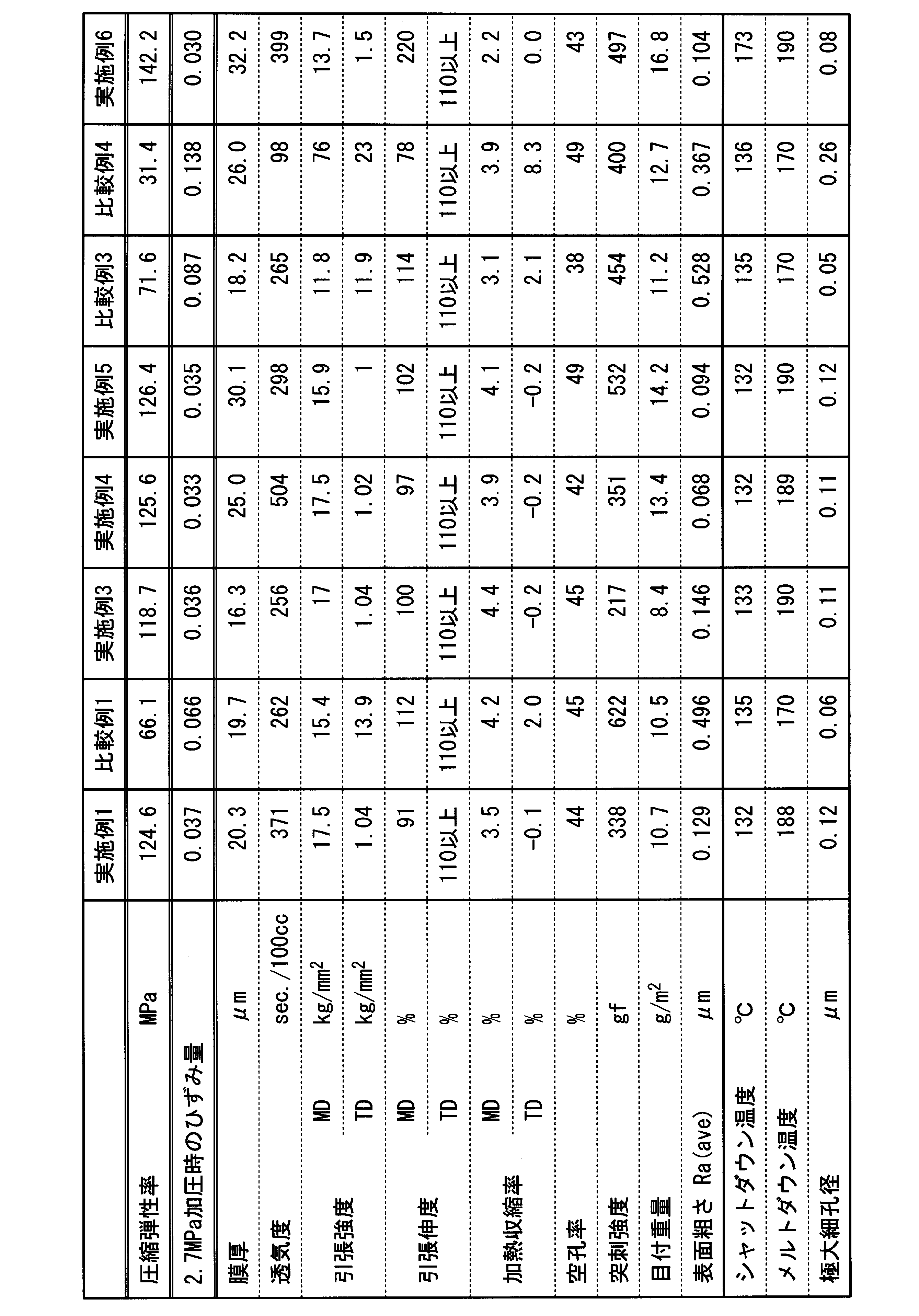
PP/PE/PPの3層を溶融状態のままTダイの中で張り合わせ、共に口金から押し出す方法で、PP/PE/PPが積層された状態の原反を製膜した。原反の厚みは、14.8μm、積層原反のC.V.は0.015であった。積層された原反を、実施例1の同様の延伸工程にて加工することで、12.5μm厚の微多孔膜を作製した。作製した微多孔膜の物性を表2に示す。
原反の膜厚を、19.2μmとした以外は、実施例7と同様にしてPP/PE/PPの三層構造の微多孔膜を作製した。微多孔膜の膜厚は16.3μmであった。物性値等の測定結果を表2に示す。
実施例1の微多孔膜に、略5μmの耐熱塗工層を塗工・乾燥させることで、24.9μm厚の微多孔膜を作製した。作製した微多孔膜の物性を表2に示す。なお、フィラーとしてベーマイトを用いてスラリーを調製して耐熱多孔質層を形成した。
実施例3のPP原反の製膜時に、PP樹脂に対し、無機絶縁体粒子として、アルミノシリケート(平均粒径2μm)を重量で4000ppmとなるように添加し、混合した以外は、実施例1と同様にしてポリオレフィン微多孔膜を得た。
実施例1のPP原反の製膜時に、PP樹脂に対し、無機絶縁体粒子として、アルミノシリケート(平均粒径2μm)を重量で4000ppmとなるように添加し、混合した以外は、実施例1と同様にしてポリオレフィン微多孔膜を得た。
実施例4のPP原反の製膜時に、PP樹脂に対し、無機絶縁体粒子として、アルミノシリケート(平均粒径2μm)を重量で4000ppmとなるように添加し、混合した以外は、実施例1と同様にしてポリオレフィン微多孔膜を得た。
実施例7と同様に、PP/PE/PPの3層を溶融状態のままTダイの中で張り合わせる方法で、共に口金から押し出す方法でPP/PE/PPが積層された状態の原反を製膜する際、PP層の樹脂量に対し無機絶縁体粒子として、アルミノシリケート(平均粒径2μm)を重量で4000ppmとなるように添加し、混合した以外は、実施例7と同様にしてポリオレフィン微多孔膜を得た。
実施例8と同様に、PP/PE/PPの3層を溶融状態のままTダイの中で張り合わせる方法で、共に口金から押し出す方法でPP/PE/PPが積層された状態の原反を製膜する際、PP層の樹脂量に対し無機絶縁体粒子として、アルミノシリケート(平均粒径2μm)を重量で4000ppmとなるように添加し、混合した以外は、実施例8と同様にしてポリオレフィン微多孔膜を得た。


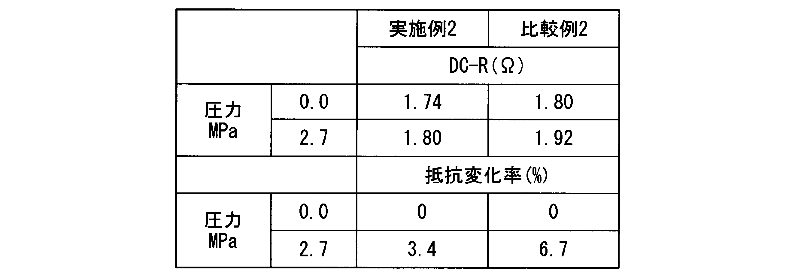
これに対して比較例3,4に記載の湿式ポリオレフィン微多孔膜では、5.8MPaの圧力を加えた場合でも急峻にガーレ値が増加した。
また実施例10~14に示すように、易滑材として機能する無機絶縁体粒子を混合した場合でも、ガーレ値が急激に増加することもなかった。
他方、比較例に示したポリオレフィン微多孔膜を用いて非水電解液電池を組み上げた場合、電池に圧力を加えた直後からガーレ値が急峻に変化し、このため電池特性に比較的大きく影響してしまう。
他方、湿式のポリオレフィン微多孔膜を用いて組み上げたラミネート型電池では、圧縮された後の電池内抵抗の変化が大きかった。
以上のことから、本発明のポリオレフィン微多孔膜を用いてリチウムイオン二次電池等の蓄電デバイスを組み上げた場合、圧縮された場合でもガーレ値が変化しにくく、このため電池特性、例えば電池内抵抗が加圧時でも変化しにくい蓄電デバイスを提供することができる。
Claims (13)
- ポリエチレンとポリプロピレンとのうちの少なくともどちらか一方を含み、
圧縮弾性率が95MPa以上150MPa以下であり、
表面と裏面について測定した膜面の表面粗さ(Ra)の平均値(Ra(ave))が0.01μm~0.30μmである、ポリオレフィン微多孔膜。 - 17.3MPaの圧力を付与した後に、圧力を解放した際のガーレ値が、圧力を付与する前のガーレ値より増加し、その増加率が0.5%以上29.0%以下である請求項1に記載のポリオレフィン微多孔膜。
- 11.5MPaの圧力を付与した後に、圧力を解放した際のガーレ値が、圧力を付与する前のガーレ値より増加し、その増加率が0.05%以上6.0%以下である請求項1に記載のポリオレフィン微多孔膜。
- 2.7MPaを付与したときの圧縮方向の応力ひずみ曲線におけるひずみ量が、0.010~0.055である請求項1に記載のポリオレフィン微多孔膜。
- TD方向の熱収縮が-1.0~1.0%であり、かつMD方向の熱収縮率が0.5~8.0%である請求項1に記載のポリオレフィン微多孔膜。
- ポリオレフィンが、ポリエチレンもしくはポリプロピレン樹脂からなる請求項1に記載のポリオレフィン微多孔膜。
- ポリプロピレン層とポリエチレン層とが積層された請求項6に記載のポリオレフィン微多孔膜。
- ポリエチレン層の両面にポリプロピレン層を設けた請求項7に記載のポリオレフィン微多孔膜。
- シャットダウン温度が130~140℃、メルトダウン温度が175以上190℃以下である請求項8に記載のポリオレフィン微多孔膜。
- ガーレ値が100~600秒/100cc、膜厚が10~40μm、突刺強度が200~700gf、水銀ポロシメータによる極大細孔径が0.05~0.3μmの範囲である請求項9に記載のポリオレフィン微多孔膜。
- 前記ポリオレフィン微多孔膜上に、耐熱性微粒子を主成分とし樹脂バインダを含む耐熱多孔質層を層設した請求項1に記載のポリオレフィン微多孔膜。
- 請求項1に記載のポリオレフィン微多孔膜を用いた蓄電デバイス用セパレータフィルム。
- 正極と、負極と、前記正極と前記負極との間に介在する請求項1に記載のポリオレフィン微多孔膜と、少なくとも前記ポリオレフィン微多孔膜に含浸される非水電解質と、を備えた蓄電デバイスであって、
2.7MPaの圧力を付与して測定したDC-R測定による抵抗値が、圧力を付与する前の抵抗値を100%としたとき、100.1~105.0%である蓄電デバイス。
Priority Applications (4)
| Application Number | Priority Date | Filing Date | Title |
|---|---|---|---|
| KR1020177035756A KR101994028B1 (ko) | 2015-06-19 | 2016-06-17 | 폴리올레핀 미다공막, 축전 디바이스용 세퍼레이터 필름 및 축전 디바이스 |
| EP16811748.9A EP3312221B1 (en) | 2015-06-19 | 2016-06-17 | Polyolefin micro porous film, separator film for power-storage device, and power-storage device |
| US15/735,057 US11329349B2 (en) | 2015-06-19 | 2016-06-17 | Polyolefin micro porous film, separator film for power-storage device, and power-storage device |
| CN201680035394.1A CN107683301B (zh) | 2015-06-19 | 2016-06-17 | 聚烯烃微多孔膜、蓄电装置用间隔体膜、以及蓄电装置 |
Applications Claiming Priority (6)
| Application Number | Priority Date | Filing Date | Title |
|---|---|---|---|
| JP2015124275 | 2015-06-19 | ||
| JP2015-124275 | 2015-06-19 | ||
| JP2015-149472 | 2015-07-29 | ||
| JP2015149472 | 2015-07-29 | ||
| JP2016-116686 | 2016-06-10 | ||
| JP2016116686A JP6094711B2 (ja) | 2015-06-19 | 2016-06-10 | ポリオレフィン微多孔膜、蓄電デバイス用セパレータフィルム、および蓄電デバイス |
Publications (1)
| Publication Number | Publication Date |
|---|---|
| WO2016204274A1 true WO2016204274A1 (ja) | 2016-12-22 |
Family
ID=57545995
Family Applications (1)
| Application Number | Title | Priority Date | Filing Date |
|---|---|---|---|
| PCT/JP2016/068113 Ceased WO2016204274A1 (ja) | 2015-06-19 | 2016-06-17 | ポリオレフィン微多孔膜、蓄電デバイス用セパレータフィルム、および蓄電デバイス |
Country Status (2)
| Country | Link |
|---|---|
| US (1) | US11329349B2 (ja) |
| WO (1) | WO2016204274A1 (ja) |
Cited By (7)
| Publication number | Priority date | Publication date | Assignee | Title |
|---|---|---|---|---|
| CN108539108A (zh) * | 2017-03-03 | 2018-09-14 | 住友化学株式会社 | 非水电解液二次电池用间隔件 |
| JP2018195564A (ja) * | 2017-05-15 | 2018-12-06 | 旭化成株式会社 | 非水系電解液電池用セパレータおよび非水電解液電池 |
| JP2020069796A (ja) * | 2018-10-31 | 2020-05-07 | 東レ株式会社 | 多孔性ポリオレフィンフィルム |
| US20200243911A1 (en) * | 2017-08-07 | 2020-07-30 | Daikin Industries, Ltd | Electrolytic solution, electrochemical device, lithium ion secondary battery, and module |
| CN113067093A (zh) * | 2019-12-12 | 2021-07-02 | 珠海恩捷新材料科技有限公司 | 一种点状涂布隔膜 |
| US11387522B2 (en) * | 2019-07-31 | 2022-07-12 | Ningde Amperex Technology Limited | Multilayer separator and device using the same |
| JP2025007578A (ja) * | 2023-07-03 | 2025-01-17 | プライムプラネットエナジー&ソリューションズ株式会社 | 非水電解質二次電池用電極体の製造方法、電極体及び電池 |
Families Citing this family (12)
| Publication number | Priority date | Publication date | Assignee | Title |
|---|---|---|---|---|
| JP7029637B2 (ja) | 2018-05-30 | 2022-03-04 | トヨタ自動車株式会社 | 水溶性高分子の多孔質体の製造方法 |
| JP6992701B2 (ja) | 2018-08-06 | 2022-01-13 | トヨタ自動車株式会社 | セパレータ一体型電極の製造方法、及び、セパレータ一体型電極 |
| KR20200065814A (ko) | 2018-11-30 | 2020-06-09 | 삼성에스디아이 주식회사 | 리튬 이차 전지용 분리막 및 이를 포함하는 리튬 이차 전지 전지 |
| WO2020195055A1 (ja) * | 2019-03-27 | 2020-10-01 | パナソニックIpマネジメント株式会社 | 二次電池 |
| JP7228459B2 (ja) | 2019-04-16 | 2023-02-24 | 住友化学株式会社 | 非水電解液二次電池用多孔質層 |
| JP7262283B2 (ja) * | 2019-04-16 | 2023-04-21 | 住友化学株式会社 | 非水電解液二次電池用多孔質層 |
| JP7240608B2 (ja) | 2019-08-29 | 2023-03-16 | トヨタ自動車株式会社 | 非水溶性高分子の多孔質体の製造方法 |
| JP7616063B2 (ja) * | 2019-11-13 | 2025-01-17 | 株式会社Gsユアサ | 非水電解質蓄電素子 |
| JP7455563B2 (ja) * | 2019-12-03 | 2024-03-26 | 株式会社Aescジャパン | 電池、フィルムの製造方法及び電池の製造方法 |
| JP7276691B2 (ja) | 2020-03-18 | 2023-05-18 | トヨタ自動車株式会社 | セパレータ一体型電極の製造方法 |
| JP7357161B2 (ja) * | 2020-05-28 | 2023-10-05 | 旭化成株式会社 | 蓄電デバイス用セパレータ |
| CN115117561A (zh) * | 2021-03-19 | 2022-09-27 | 住友化学株式会社 | 非水电解液二次电池用层叠体、非水电解液二次电池用部件和非水电解液二次电池 |
Citations (5)
| Publication number | Priority date | Publication date | Assignee | Title |
|---|---|---|---|---|
| JP2010247446A (ja) * | 2009-04-16 | 2010-11-04 | Nitto Denko Corp | 多孔質シートの製造方法及び多孔質シート |
| JP2011028883A (ja) * | 2009-07-22 | 2011-02-10 | Panasonic Corp | 非水電解質二次電池 |
| JP2012161936A (ja) * | 2011-02-03 | 2012-08-30 | Asahi Kasei E-Materials Corp | 積層微多孔性フィルムの製造方法、及び電池用セパレータ |
| JP2013023673A (ja) * | 2011-07-26 | 2013-02-04 | Asahi Kasei E-Materials Corp | 微多孔性フィルム及び電池用セパレータ |
| JP2014141644A (ja) * | 2012-12-26 | 2014-08-07 | Toray Ind Inc | 二軸配向多孔性ポリプロピレンフィルム、蓄電デバイス用セパレータフィルムおよび蓄電デバイス |
Family Cites Families (20)
| Publication number | Priority date | Publication date | Assignee | Title |
|---|---|---|---|---|
| ZA707453B (en) | 1969-11-13 | 1972-06-28 | Celanese Corp | Novel open-celled microporous film |
| JPS5031791B1 (ja) | 1969-12-27 | 1975-10-15 | ||
| JPS6023130B2 (ja) | 1979-04-02 | 1985-06-06 | 旭化成株式会社 | ポリオレフィン多孔物の製造方法 |
| JP3003830B2 (ja) | 1994-05-12 | 2000-01-31 | 宇部興産株式会社 | 積層多孔質フイルム及びその製法 |
| JP4209985B2 (ja) | 1999-01-22 | 2009-01-14 | 旭化成ケミカルズ株式会社 | ポリオレフィン系微多孔膜 |
| JP4876387B2 (ja) * | 2003-11-05 | 2012-02-15 | 東レ株式会社 | 二軸配向微多孔フィルムおよびその製造方法 |
| JP2007087690A (ja) | 2005-09-21 | 2007-04-05 | Matsushita Electric Ind Co Ltd | 非水電解液二次電池 |
| EP2108675B1 (en) | 2007-01-30 | 2011-12-21 | Asahi Kasei E-materials Corporation | Microporous polyolefin membrane |
| KR101347460B1 (ko) | 2007-10-12 | 2014-01-03 | 도레이 배터리 세퍼레이터 필름 주식회사 | 미세다공성 막 및 이의 제조 및 사용 방법 |
| US8338017B2 (en) | 2007-10-12 | 2012-12-25 | Toray Battery Separator Film Co., Ltd. | Microporous membrane and manufacturing method |
| KR100947072B1 (ko) | 2008-03-27 | 2010-04-01 | 삼성에스디아이 주식회사 | 전극조립체 및 이를 구비하는 이차전지 |
| US8771859B2 (en) * | 2009-03-13 | 2014-07-08 | Hitachi Maxell, Ltd. | Separator for battery and nonaqueous electrolyte battery using same |
| JP2011154936A (ja) | 2010-01-28 | 2011-08-11 | Hitachi Maxell Ltd | 電池用セパレータおよびリチウム二次電池 |
| JP5459139B2 (ja) | 2010-08-05 | 2014-04-02 | トヨタ自動車株式会社 | 組電池 |
| JP5512461B2 (ja) | 2010-08-10 | 2014-06-04 | 旭化成イーマテリアルズ株式会社 | 微多孔性フィルム及び電池用セパレータ |
| DE102012004161A1 (de) | 2012-03-05 | 2013-09-05 | Treofan Germany Gmbh & Co. Kg | Hochporöse Separator-Folie mit partieller Beschichtung |
| CN103407140B (zh) | 2013-07-26 | 2015-07-01 | 常州大学 | 一种pp/pe/pp三层复合微孔膜的制备方法 |
| CN103465476B (zh) * | 2013-09-03 | 2016-04-20 | 深圳中兴创新材料技术有限公司 | 一种聚烯烃微孔膜的制备方法、聚烯烃微孔膜及其应用 |
| KR102100244B1 (ko) * | 2013-12-19 | 2020-04-13 | 에스케이이노베이션 주식회사 | 리튬 이차전지 전해액 및 이를 포함하는 리튬 이차전지 |
| US10490796B2 (en) * | 2014-02-19 | 2019-11-26 | Sion Power Corporation | Electrode protection using electrolyte-inhibiting ion conductor |
-
2016
- 2016-06-17 WO PCT/JP2016/068113 patent/WO2016204274A1/ja not_active Ceased
- 2016-06-17 US US15/735,057 patent/US11329349B2/en active Active
Patent Citations (5)
| Publication number | Priority date | Publication date | Assignee | Title |
|---|---|---|---|---|
| JP2010247446A (ja) * | 2009-04-16 | 2010-11-04 | Nitto Denko Corp | 多孔質シートの製造方法及び多孔質シート |
| JP2011028883A (ja) * | 2009-07-22 | 2011-02-10 | Panasonic Corp | 非水電解質二次電池 |
| JP2012161936A (ja) * | 2011-02-03 | 2012-08-30 | Asahi Kasei E-Materials Corp | 積層微多孔性フィルムの製造方法、及び電池用セパレータ |
| JP2013023673A (ja) * | 2011-07-26 | 2013-02-04 | Asahi Kasei E-Materials Corp | 微多孔性フィルム及び電池用セパレータ |
| JP2014141644A (ja) * | 2012-12-26 | 2014-08-07 | Toray Ind Inc | 二軸配向多孔性ポリプロピレンフィルム、蓄電デバイス用セパレータフィルムおよび蓄電デバイス |
Cited By (12)
| Publication number | Priority date | Publication date | Assignee | Title |
|---|---|---|---|---|
| CN108539108A (zh) * | 2017-03-03 | 2018-09-14 | 住友化学株式会社 | 非水电解液二次电池用间隔件 |
| JP2018147688A (ja) * | 2017-03-03 | 2018-09-20 | 住友化学株式会社 | 非水電解液二次電池用セパレータ |
| CN108539108B (zh) * | 2017-03-03 | 2019-11-15 | 住友化学株式会社 | 非水电解液二次电池用间隔件 |
| JP2018195564A (ja) * | 2017-05-15 | 2018-12-06 | 旭化成株式会社 | 非水系電解液電池用セパレータおよび非水電解液電池 |
| US20200243911A1 (en) * | 2017-08-07 | 2020-07-30 | Daikin Industries, Ltd | Electrolytic solution, electrochemical device, lithium ion secondary battery, and module |
| US11611106B2 (en) * | 2017-08-07 | 2023-03-21 | Daikin Industries, Ltd. | Electrolytic solution, electrochemical device, lithium ion secondary battery, and module |
| JP2020069796A (ja) * | 2018-10-31 | 2020-05-07 | 東レ株式会社 | 多孔性ポリオレフィンフィルム |
| JP7306200B2 (ja) | 2018-10-31 | 2023-07-11 | 東レ株式会社 | 多孔性ポリオレフィンフィルム |
| US11387522B2 (en) * | 2019-07-31 | 2022-07-12 | Ningde Amperex Technology Limited | Multilayer separator and device using the same |
| CN113067093A (zh) * | 2019-12-12 | 2021-07-02 | 珠海恩捷新材料科技有限公司 | 一种点状涂布隔膜 |
| JP2025007578A (ja) * | 2023-07-03 | 2025-01-17 | プライムプラネットエナジー&ソリューションズ株式会社 | 非水電解質二次電池用電極体の製造方法、電極体及び電池 |
| JP7866968B2 (ja) | 2023-07-03 | 2026-05-28 | プライムプラネットエナジー&ソリューションズ株式会社 | 非水電解質二次電池用電極体の製造方法、電極体及び電池 |
Also Published As
| Publication number | Publication date |
|---|---|
| US11329349B2 (en) | 2022-05-10 |
| US20180175353A1 (en) | 2018-06-21 |
Similar Documents
| Publication | Publication Date | Title |
|---|---|---|
| JP6094711B2 (ja) | ポリオレフィン微多孔膜、蓄電デバイス用セパレータフィルム、および蓄電デバイス | |
| JP6696518B2 (ja) | ポリオレフィン微多孔膜 | |
| JP6773044B2 (ja) | 多孔膜および蓄電デバイス | |
| US11329349B2 (en) | Polyolefin micro porous film, separator film for power-storage device, and power-storage device | |
| US20240243432A1 (en) | Separator including polyethylene with highly entangled polymer chains, and electrochemical device including the same | |
| JP6436248B2 (ja) | セパレータおよび蓄電デバイス | |
| CN102124591B (zh) | 电池用隔膜以及使用其的非水电解液电池 | |
| EP4231432A1 (en) | Porous substrate for separator, and separator for electrochemical device comprising same | |
| CN113226732B (zh) | 聚烯烃微多孔膜及蓄电装置 | |
| WO2017138512A1 (ja) | ポリオレフィン微多孔膜、蓄電デバイス用セパレータフィルム、及び蓄電デバイス | |
| WO2025033202A1 (ja) | ポリオレフィン微多孔膜、それを用いた蓄電デバイス用セパレータフィルム、及び蓄電デバイス |
Legal Events
| Date | Code | Title | Description |
|---|---|---|---|
| 121 | Ep: the epo has been informed by wipo that ep was designated in this application |
Ref document number: 16811748 Country of ref document: EP Kind code of ref document: A1 |
|
| WWE | Wipo information: entry into national phase |
Ref document number: 15735057 Country of ref document: US |
|
| ENP | Entry into the national phase |
Ref document number: 20177035756 Country of ref document: KR Kind code of ref document: A |
|
| NENP | Non-entry into the national phase |
Ref country code: DE |
|
| WWE | Wipo information: entry into national phase |
Ref document number: 2016811748 Country of ref document: EP |