WO2016208037A1 - プログラム生成装置、プログラム生成方法および生成プログラム - Google Patents
プログラム生成装置、プログラム生成方法および生成プログラム Download PDFInfo
- Publication number
- WO2016208037A1 WO2016208037A1 PCT/JP2015/068371 JP2015068371W WO2016208037A1 WO 2016208037 A1 WO2016208037 A1 WO 2016208037A1 JP 2015068371 W JP2015068371 W JP 2015068371W WO 2016208037 A1 WO2016208037 A1 WO 2016208037A1
- Authority
- WO
- WIPO (PCT)
- Prior art keywords
- image
- program
- image processing
- evaluation value
- output
- Prior art date
- Legal status (The legal status is an assumption and is not a legal conclusion. Google has not performed a legal analysis and makes no representation as to the accuracy of the status listed.)
- Ceased
Links
Images


Classifications
-
- G—PHYSICS
- G06—COMPUTING OR CALCULATING; COUNTING
- G06V—IMAGE OR VIDEO RECOGNITION OR UNDERSTANDING
- G06V10/00—Arrangements for image or video recognition or understanding
- G06V10/70—Arrangements for image or video recognition or understanding using pattern recognition or machine learning
- G06V10/77—Processing image or video features in feature spaces; using data integration or data reduction, e.g. principal component analysis [PCA] or independent component analysis [ICA] or self-organising maps [SOM]; Blind source separation
- G06V10/774—Generating sets of training patterns; Bootstrap methods, e.g. bagging or boosting
-
- G—PHYSICS
- G06—COMPUTING OR CALCULATING; COUNTING
- G06F—ELECTRIC DIGITAL DATA PROCESSING
- G06F18/00—Pattern recognition
- G06F18/20—Analysing
- G06F18/21—Design or setup of recognition systems or techniques; Extraction of features in feature space; Blind source separation
- G06F18/214—Generating training patterns; Bootstrap methods, e.g. bagging or boosting
-
- G—PHYSICS
- G06—COMPUTING OR CALCULATING; COUNTING
- G06F—ELECTRIC DIGITAL DATA PROCESSING
- G06F8/00—Arrangements for software engineering
- G06F8/30—Creation or generation of source code
- G06F8/36—Software reuse
-
- G—PHYSICS
- G06—COMPUTING OR CALCULATING; COUNTING
- G06F—ELECTRIC DIGITAL DATA PROCESSING
- G06F9/00—Arrangements for program control, e.g. control units
- G06F9/06—Arrangements for program control, e.g. control units using stored programs, i.e. using an internal store of processing equipment to receive or retain programs
- G06F9/44—Arrangements for executing specific programs
-
- G—PHYSICS
- G06—COMPUTING OR CALCULATING; COUNTING
- G06N—COMPUTING ARRANGEMENTS BASED ON SPECIFIC COMPUTATIONAL MODELS
- G06N3/00—Computing arrangements based on biological models
- G06N3/12—Computing arrangements based on biological models using genetic models
-
- G—PHYSICS
- G06—COMPUTING OR CALCULATING; COUNTING
- G06N—COMPUTING ARRANGEMENTS BASED ON SPECIFIC COMPUTATIONAL MODELS
- G06N3/00—Computing arrangements based on biological models
- G06N3/12—Computing arrangements based on biological models using genetic models
- G06N3/126—Evolutionary algorithms, e.g. genetic algorithms or genetic programming
-
- G—PHYSICS
- G06—COMPUTING OR CALCULATING; COUNTING
- G06T—IMAGE DATA PROCESSING OR GENERATION, IN GENERAL
- G06T5/00—Image enhancement or restoration
- G06T5/20—Image enhancement or restoration using local operators
-
- G—PHYSICS
- G06—COMPUTING OR CALCULATING; COUNTING
- G06T—IMAGE DATA PROCESSING OR GENERATION, IN GENERAL
- G06T7/00—Image analysis
-
- G—PHYSICS
- G06—COMPUTING OR CALCULATING; COUNTING
- G06V—IMAGE OR VIDEO RECOGNITION OR UNDERSTANDING
- G06V10/00—Arrangements for image or video recognition or understanding
- G06V10/94—Hardware or software architectures specially adapted for image or video understanding
-
- G—PHYSICS
- G06—COMPUTING OR CALCULATING; COUNTING
- G06V—IMAGE OR VIDEO RECOGNITION OR UNDERSTANDING
- G06V10/00—Arrangements for image or video recognition or understanding
- G06V10/96—Management of image or video recognition tasks
Definitions
- the present invention relates to a program generation device, a program generation method, and a generation program.
- an image processing program generated by combining a partial program for image processing for example, an image filter program
- learning data such as a set of an input image and a processing result image (target image)
- target image a processing result image
- a genetic processing device has been proposed in which the converter is evolved using the weight data of the current generation and the weight data used in the generation before the previous generation. Yes.
- the following survival selection method is used.
- An input image included in the learning data is processed using a program corresponding to the individual generated in the learning process.
- the output image output as the processing result is compared with the target image included in the learning data, and it is determined whether to leave the individual in the next generation based on the comparison result.
- this method has a problem that, depending on the contents of the image processing, a useful solid that promotes learning may be deceived. Such a problem can cause a long time for the generation processing of the image processing program.
- an object of the present invention is to provide a program generation device, a program generation method, and a generation program capable of optimizing survival selection when generating an image processing program by genetic programming.
- a program generator that generates a program by genetic programming.
- This program generation device includes a storage unit and a calculation unit.
- the storage unit stores learning data including the input image and the first target image.
- a 1st target image shows the image output in the middle of the process which converts an input image into a 2nd target image.
- the calculation unit selects a first program from a plurality of image processing programs each of which is a combination of a plurality of partial programs, and generates a second program by changing a part of the partial programs included in the first program , Execute image processing on the input image using the second program, and determine whether to leave the second program in the next generation based on a comparison between the intermediate output image output during the image processing and the first target image If it is determined that the second program is left for the next generation, one of the plurality of image processing programs is replaced with the second program.
- a program generation method in which a computer executes the same processing as the above-described program generation device. Furthermore, in one proposal, a generation program that causes a computer to execute the same processing as that of the above-described program generation apparatus is provided.
- survival selection when generating an image processing program by genetic programming can be optimized.
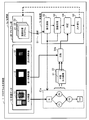
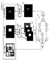
- FIG. 1 is a diagram illustrating a configuration example and a processing example of the program generation device according to the first embodiment.
- the program generation apparatus 1 is an apparatus that generates an image processing program by genetic programming.
- the program generation device 1 includes a storage unit 1a and a calculation unit 1b.
- the storage unit 1a is implemented as, for example, a volatile storage device such as a RAM (Random Access Memory) or a nonvolatile storage device such as an HDD (Hard Disk Drive) or a flash memory.
- the computing unit 1b is, for example, a processor.
- the storage unit 1a stores learning data 10.
- the learning data 10 includes an input image 11, a first target image 12, and a second target image 13.
- the second target image 13 is an image that is a target of an image that is output as a processing result when the input image 11 is subjected to image processing.
- the first target image 12 becomes a target of an image output at some stage during the image processing when the image processing for converting the input image 11 into the second target image 13 is performed. It is an image.
- the first target image 12 includes the specific image area in the image and the other image area (background area). Differentiated images can be used.
- Each image area can be distinguished by assigning a pixel value, for example, the pixel value of a specific image area is set to the maximum value and the pixel value of the background image area is set to the minimum value (0).
- a plurality of sets of learning data 10 may be stored in the storage unit 1a.
- the storage unit 1a may store the program group 20.
- the program group 20 is data used in the processing of the arithmetic unit 1b, and includes a plurality of image processing programs 21, 22, 23,.
- the image processing programs 21, 22, 23,... Included in the program group 20 are generated by combining a plurality of partial programs.
- the partial program is a program component for executing image processing such as an image filter.
- the program generation device 1 generates an image processing program for executing desired image processing by preferentially leaving an image processing program having high fitness in the program group 20 every time the generation of the program group 20 is updated. To do.
- the calculation unit 1b selects an image processing program from the program group 20 (step S1).
- the image processing program 21 is selected.
- the computing unit 1b changes the part of the partial program included in the selected image processing program 21 to generate the image processing program 21a.
- This process is a process of evolving the image processing program 21 (step S2). In this evolution process, for example, crossover between the image processing program 21 and another image processing program selected from the program group 20, or mutation of the image processing program 21 or the program after the crossover is performed.
- an image processing program 21a in which partial programs P1 to P3 are combined is generated by the evolution process.
- “In” indicates an input unit of the image processing program 21a
- “Out” indicates an output unit of the image processing program 21a.
- the computing unit 1b executes image processing on the input image 11 using the image processing program 21a (step S3).
- the calculation unit 1b outputs an intermediate output image during the image processing.
- the intermediate output image is an image output as a processing result of each of the partial programs P1 and P2 excluding the partial program P3 incorporated in the final stage among the partial programs P1 to P3 included in the image processing program 21a.
- the intermediate output image 31 is output as the processing result of the partial program P1
- the intermediate output image 32 is output as the processing result of the partial program P2.
- step S4 determines whether to leave the generated image processing program 21a for the next generation.
- the process of step S4 includes a process of comparing the intermediate output images 31 and 32 and the first target image 12 (step S4a).
- step S4a for example, the similarity between images is output as a comparison result.
- the comparison result is, for example, the intermediate output images 31 and 32 and the first target image 12.
- the maximum value of each similarity with the target image 12 is output.
- the computing unit 1b determines whether to leave the image processing program 21a for the next generation based on the comparison result in step S4a.
- step S4 determination is performed using not only the comparison result in step S4a but also the comparison result between the final output image output as the execution result of the image processing program 21a and the second target image 13. Also good.
- step S4 When it is determined in step S4 that the image processing program 21a is left for the next generation, the calculation unit 1b replaces one of the image processing programs 21, 22, 23,... Included in the program group 20 with the image processing program 21a. (Step S5). Thereby, the generation of the program group 20 is updated.
- a method is conceivable. However, in this method, even if an image close to a desired image such as the first target image 12 is generated during image processing, if the final image and the second target image 13 are not similar, The image processing program 21 a is deceived and does not remain in the next-generation program group 20. In this way, if an effective image processing program that is likely to be useful for promoting learning is deceived, it can be a cause of increasing the time taken to complete generation of the image processing program.
- the comparison result in step S4a indicates an index as to whether the intermediate output image output during the execution of the image processing program 21a is close to the desired image.
- an image processing program that is likely to be able to output an appropriate image during the execution of the image processing program 21a is not deceived, and the next-generation program group 20 Will remain.
- the survival selection is optimized so that an image processing program whose processing process is designated as appropriate is likely to remain in the next generation.
- step S4a the speed at which the degree of closeness between the images indicated by the comparison result in step S4a increases. It speeds up and learning speed improves. Thereby, the time until the maximum value of the fitness of the image processing programs included in the program group 20 and the image processing programs generated from the image processing programs by the evolution process reaches a predetermined threshold is shortened. That is, the time until an image processing program that realizes a desired process is generated is shortened.
- the image processing apparatus according to the second embodiment has a processing function similar to that of the program generation apparatus 1 shown in FIG. 1 and a function of executing an image processing program generated by this processing function to perform image processing. Prepare.
- FIG. 2 is a diagram illustrating a comparative example of the generation processing procedure of the image processing program.
- One or more learning data 50 are prepared before the image processing program generation process.
- the learning data 50 includes an input image 51 and a target image 52 when image processing is performed on the input image 51.
- the input image 51 is obtained, for example, by capturing a subject with a camera.
- an individual is configured by combining one or more partial programs. For example, as shown in the upper left of FIG. 2, an individual is defined by a tree structure.
- a plurality of partial programs that can be incorporated into individuals are also prepared in advance.
- an image filter is assumed as an example of a partial program incorporated in an individual.
- the partial program is not limited to an image filter, and a program for performing other types of image processing can also be used.
- F indicates an image filter
- I indicates an input terminal
- O indicates an output terminal.
- the generation processing of the image processing program by genetic programming is executed as follows, for example. First, a group 61 of a plurality of initial individuals is generated (step S11). In each initial individual node, an image filter is randomly selected from a plurality of image filters prepared in advance and incorporated. Next, two parent individuals are randomly extracted from the generated individual group 61 (step S12).
- the evolution process is performed on these two parent individuals to generate two or more child individuals (step S13).
- crossover processing and mutation processing are performed on two parent individuals.
- Three or more child individuals may be generated by performing different crossover processing and mutation processing on the two parent individuals.
- the fitness is calculated for each of the child individual generated through the evolution process and the original parent individual (step S14).
- image processing using each target individual is performed on the input image 51 of the learning data 50, and the fitness is calculated by comparing the image after execution with the corresponding target image 52.
- the average value of the fitness obtained using the plurality of learning data 50 is calculated for each individual.
- the individual is output as a final image processing program, and the program generation process ends.
- survival selection is performed from the generated individual group 62 including each child individual and the original two parent individuals (step S15). ).
- an individual having the maximum calculated fitness is selected from the individual group 62.
- one individual is selected from the remaining individuals in the individual group 62 by a predetermined method. For example, an individual is selected from the remaining individuals with a probability corresponding to the fitness.
- the two individuals selected by such survival selection are replaced with two individuals included in the individual group 61 (step S16).
- the two individuals selected by the survival selection are replaced with two individuals extracted as parent individuals among the individuals included in the individual group 61.
- the individuals included in the individual group 61 are changed to the next generation individuals. Then, the same processing is repeated until an individual whose fitness is equal to or greater than a predetermined threshold appears.
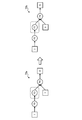
- FIG. 3 is a diagram showing an example of crossover.
- FIG. 3 shows an example in which crossover is performed between a parent individual 71a and a parent individual 72a, and a child individual 71b based on the parent individual 71a and a child individual 72b based on the parent individual 72a are generated.
- the parent individual 71a includes image filters F1, F2, F3, and F4, and the parent individual 72a includes image filters F2, F3, F5, and F6.
- the node of the image filter F2 in the parent individual 71a and the node of the image filter F5 in the parent individual 72a are selected as locations to be crossed.
- FIG. 4 is a diagram showing an example of mutation.
- the individual 73a includes image filters F3, F4, and F5.
- the individual 73a may be, for example, a parent individual extracted from the individual group 61, or may be an individual that has been extracted from the individual group 61 as a parent individual and then crossed.
- the node of the image filter F3 in the individual 73a is selected as a location to be mutated and the image filter F7 is selected as an image filter after replacement by mutation.
- the image filter after replacement by mutation is randomly selected from a plurality of image filters prepared in advance. By such mutation, a child individual 73b including the image filters F4, F5, and F7 is generated.
- a use of performing image processing on an image obtained by capturing a product to obtain a desired effect can be considered.
- image processing can be performed on an image obtained by capturing the appearance of a product to extract a portion where a defect has occurred, a portion to be aligned is extracted, or a character printed on a specific part can be recognized. .
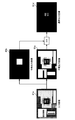
- FIG. 5 is a diagram showing an example of image processing.
- image processing there is one in which some specific processing is performed on a specific region in the input image.
- FIG. 5 shows, as an example, processing for extracting only a character portion printed in the area from a package area of a semiconductor chip mounted on a printed board as a specific color (for example, white) area.
- a specific color for example, white
- the final output image 81d that is finally output as a result of the image processing, only the character portion “ABC123” printed in the package area of the semiconductor chip is extracted as a white area.
- the image processing of FIG. 5 is executed as preprocessing for recognizing characters from a specific area, for example.
- Another example of the process of performing a certain process on a specific area is a process of extracting a symbol or pattern portion drawn on a part as a specific color area from the area where the specific part is mounted. Conceivable.
- a process of extracting only the part mounting area in that area as a specific color area may be considered.
- extraction target region a specific region from which characters, symbols, and patterns are to be extracted.
- the degree of variation in the brightness of the extraction target area in the image is often different from the degree of variation in the brightness of the background area other than that area. This is because the cause of variation in brightness may differ between the extraction target area and the background area.
- the light reflectance and color tendencies may be different between the extraction target region and the background region, or the way light from the surroundings varies depending on the height difference between the extraction target region and the background region. .
- an example of an image in which the extracted region and the other background region are distinguished from each other is a mask image in which the background region other than the extracted region is masked.
- the extracted area is a white area (that is, an area having a maximum pixel value)
- the other background area is a black area (that is, an area having a minimum pixel value).
- the intermediate output image 81b shown in FIG. 5 is an example of a mask image generated by the above intermediate processing algorithm.
- This intermediate processing algorithm is, for example, for extracting a color area similar to the package area of the semiconductor chip from the input image 81a.
- the image processing shown in FIG. 5 includes, for example, processing for extracting a color region similar to the character to be extracted from the input image 81a.
- An intermediate output image 81c shown in FIG. 5 is an example of an image obtained by such processing.
- the final output image 81d is generated by taking the logical product (and) of the intermediate processed image 81b and the intermediate processed image 81c.
- a method of generating an image processing program after setting a region of interest (Region ⁇ Of Interest: ROI) corresponding to an extraction target region on an input image in advance Conceivable.
- this method can be applied only to image processing for an image existing in a place where an extraction target area is determined.
- a method of separately learning a program for performing a region of interest extraction process and a program for performing a subsequent process may be considered.
- the entire program generation time is increased by performing learning multiple times.
- FIG. 6 is a diagram showing an overview of an individual evaluation procedure according to the second embodiment.
- the image processing apparatus evaluates an individual according to the procedure shown in FIG.
- a combination of the input image 82a, the intermediate target image 82b, and the final target image 82c is prepared as the learning data 82.
- the final target image 82c is a target image for an image that is finally output by image processing using an individual to be evaluated.
- the intermediate target image 82b is a target image for an image output at a stage in the middle of image processing using the individual to be evaluated, that is, at any node other than the final node of the individual.
- the intermediate target image 82b is a mask image for masking an area (background area) other than the extraction target area.
- FIG. 6 shows an individual 74 having image filters F1 to F9 as an example of an individual to be evaluated.
- the image processing apparatus uses the input image 82a as input and executes image processing using the individual 74 to be evaluated. Then, the image processing apparatus acquires an output image output from each node in which the image filter (partial program) is incorporated in the individual 74.
- the acquired output images are roughly classified into intermediate output images 83a, 83b, 83c,... Output at each node (intermediate node) excluding the final node, and final output image 84 output at the final node. Is done. That is, the image processing apparatus acquires output images from other image filters F1 to F9 excluding the image filter F9 incorporated in the final node of the individual 74 as intermediate output images 83a, 83b, 83c,. Further, the image processing apparatus acquires an output image from the image filter F9 incorporated in the final node of the individual 74 (that is, the final output image of the individual 74) as the final output image 84.
- the image processing apparatus is based on the comparison result between each of the acquired intermediate output images 83a, 83b, 83c,. Thus, it is determined whether or not the individual 74 is left for the next generation.
- the image processing apparatus compares the acquired final output image 84 with the final target image 82c, and calculates a final evaluation value 85b based on the comparison result.
- the calculation method can be the same as that in step S14 in FIG. 2, for example, the similarity between the final output image 84 and the final target image 82c is calculated as the final evaluation value 85b.
- the image processing apparatus compares the acquired intermediate output images 83a, 83b, 83c,... With the intermediate target image 82b, and calculates an intermediate evaluation value 85a based on the comparison result. For example, the image processing apparatus calculates the similarity between each of the intermediate output images 83a, 83b, 83c,... And the intermediate target image 82b, and sets the maximum value of the calculated similarities as the intermediate evaluation value 85a. To do.
- the image processing apparatus determines whether or not to leave the individual 74 in the next generation based on the intermediate evaluation value 85a and the final evaluation value 85b. For example, it is determined whether or not the individual 74 is left in the next generation based on an evaluation value obtained by combining the intermediate evaluation value 85a and the final evaluation value 85b at a ratio according to the weighting coefficient.
- the image processing apparatus can use a value calculated by weighting the intermediate evaluation value and the final evaluation value as an evaluation value for determining whether to leave the individual in the next generation. For example, the image processing apparatus uses an evaluation value calculated by increasing the weight of the intermediate evaluation value in the initial stage of learning, and gradually increases the weight of the final evaluation value when calculating the evaluation value as the learning progresses. Make it bigger. Thereby, in the initial stage of learning, learning is performed so that importance is attached to the intermediate output image approaching the intermediate target image. As learning progresses and the intermediate evaluation value converges, it is important that the final output image approaches the final target image. As the number of individuals having a high intermediate evaluation value increases in the individual group 61, the time until the final evaluation value reaches a predetermined threshold is shortened. Therefore, the image processing program can be generated as a whole by changing the weight as described above. Time to complete is reduced.
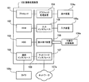
- FIG. 7 is a diagram illustrating a hardware configuration example of the image processing apparatus.
- the image processing apparatus 100 is realized as a computer as shown in FIG. 7, for example.
- the entire image processing apparatus 100 is controlled by a processor 101.
- the processor 101 may be a multiprocessor.
- the processor 101 is, for example, a CPU (Central Processing Unit), an MPU (Micro Processing Unit), a DSP (Digital Signal Processor), an ASIC (Application Specific Integrated Circuit), or a PLD (Programmable Logic Device).
- the processor 101 may be a combination of two or more elements among CPU, MPU, DSP, ASIC, and PLD.
- a RAM (Random Access Memory) 102 and a plurality of peripheral devices are connected to the processor 101 via a bus 109.
- the RAM 102 is used as a main storage device of the image processing apparatus 100.
- the RAM 102 temporarily stores at least part of an OS (Operating System) program and application programs to be executed by the processor 101.
- the RAM 102 stores various data necessary for processing by the processor 101.
- Peripheral devices connected to the bus 109 include an HDD 103, a graphic processing device 104, an input interface 105, a reading device 106, a network interface 107, and a communication interface 108.
- the HDD 103 is used as an auxiliary storage device of the image processing apparatus 100.
- the HDD 103 stores an OS program, application programs, and various data.
- As the auxiliary storage device other types of nonvolatile storage devices such as SSD (SolidSoState Drive) can be used.
- the graphic processing device 104 is connected to a display device 104a.
- the graphic processing device 104 displays an image on the screen of the display device 104a in accordance with an instruction from the processor 101.
- Examples of the display device include a liquid crystal display and an organic EL (ElectroLuminescence) display.
- the input device 105 a is connected to the input interface 105.
- the input interface 105 transmits a signal output from the input device 105a to the processor 101.
- Examples of the input device 105a include a keyboard and a pointing device.
- Examples of pointing devices include a mouse, a touch panel, a tablet, a touch pad, and a trackball.
- the portable recording medium 106a is detached from the reading device 106.
- the reading device 106 reads the data recorded on the portable recording medium 106 a and transmits it to the processor 101.
- Examples of the portable recording medium 106a include an optical disk, a magneto-optical disk, and a semiconductor memory.
- the network interface 107 transmits and receives data to and from other devices via the network 107a.
- the communication interface 108 transmits / receives data to / from a connected external device.
- a camera 108 a is connected as an external device to the communication interface 108, and the communication interface 108 transmits image data transmitted from the camera 108 a to the processor 101.
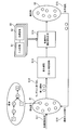
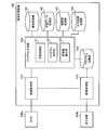
- FIG. 8 is a block diagram illustrating a configuration example of processing functions included in the image processing apparatus.
- the image processing apparatus 100 includes an image acquisition unit 111, an image processing unit 112, a program generation unit 120, a program storage unit 130, an element storage unit 141, a learning data storage unit 142, an individual group storage unit 143, and an output image storage unit 144. .
- the processing of the image acquisition unit 111, the image processing unit 112, and the program generation unit 120 is realized by, for example, the processor 101 of the image processing apparatus 100 executing a predetermined program. Part of the processing of the image processing unit 112 is realized by the processor 101 of the image processing apparatus 100 executing an image processing program stored in the program storage unit 130.
- the program storage unit 130, the element storage unit 141, and the learning data storage unit 142 are realized as a storage area of the HDD 103 of the image processing apparatus 100, for example.
- the individual group storage unit 143 and the output image storage unit 144 are realized as a storage area of the RAM 102 of the image processing apparatus 100, for example.
- the image acquisition unit 111 acquires captured image data from the camera 108 a and outputs the acquired data to the program generation unit 120 or the image processing unit 112.
- the program generation unit 120 generates an image processing program by genetic programming, and stores the generated image processing program in the program storage unit 130.
- the internal configuration of the program generation unit 120 will be described later.
- the image processing unit 112 acquires image data captured by the camera 108 a via the image acquisition unit 111.
- the image processing unit 112 performs image processing on the acquired image data in accordance with an image processing program stored in the program storage unit 130.
- the processed image is displayed on the display device 104a, for example.
- the program storage unit 130 stores the image processing program generated by the program generation unit 120.
- the element storage unit 141 stores element data that can be incorporated into each individual generated by the program generation unit 120. These elements are partial programs that are components of the image processing program, and include, for example, various image filter programs.
- the learning data storage unit 142 stores a plurality of pieces of learning data including input images and intermediate target image and final target image data corresponding to the input images.
- the input image included in the learning data may be, for example, an image captured by the camera 108a connected to the image processing apparatus 100.
- the intermediate target image and the final target image corresponding to the input image are created, for example, by performing a retouch process on the input image.
- the individual group storage unit 143 stores the individual group.
- the individual group includes a plurality of individuals (image processing programs) generated by combining elements (partial programs) stored in the element storage unit 141.
- the individual group storage unit 143 may store the image processing program itself corresponding to each individual, or structure information indicating a partial program name incorporated in each node of the individual and a connection structure between the nodes. It may be stored for each individual. Further, the individual group storage unit 143 stores the evaluation value calculated for each individual in association with the individual.
- the output image storage unit 144 stores an output image obtained by executing a program corresponding to an individual subject to survival selection. As this output image, there are an intermediate output image output at the intermediate node of the individual and a final output image output at the final node of the individual.
- the program generation unit 120 includes a learning control unit 121, a program execution unit 122, and an evaluation value calculation unit 123.
- the learning control unit 121 comprehensively controls the entire program generation process in the program generation unit 120.
- the learning control unit 121 executes processes such as initial population generation, individual evolution processing, survival selection based on evaluation values and output of a final image processing program, and population update by individuals selected for survival. To do.
- the program execution unit 122 executes an individual (image processing program) in response to an instruction from the learning control unit 121.
- the program execution unit 122 outputs not only the final output image output at the final node of the individual but also the intermediate output image output at the intermediate node of the individual by the execution of the individual, and stores it in the output image storage unit 144 To do.
- Evaluation value calculation unit 123 calculates an evaluation value for evaluating each individual in response to an instruction from learning control unit 121.
- the calculated evaluation value includes a comprehensive evaluation value in addition to the intermediate evaluation value and the final evaluation value described above.
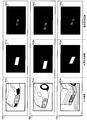
- FIG. 9 is a diagram illustrating a first example of learning data.
- an image process is assumed in which only the character portion printed in the area is extracted as a white area from the package area of the semiconductor chip mounted on the printed board.
- the extraction target area that is a character extraction target is a package area of the semiconductor chip.
- Learning data 151 includes an input image 151a, an intermediate target image 151b, and a final target image 151c.
- the input image 151a shows a printed circuit board.
- the intermediate target image 151b is a mask image obtained by masking a background area other than the package area (extraction target area) of the semiconductor chip in the input image 151a.
- the final target image 151c is an image in which only the character portion printed in the package area of the semiconductor chip in the input image 151a is white.
- Learning data 152 includes an input image 152a, an intermediate target image 152b, and a final target image 152c.
- the input image 152a shows a printed circuit board. However, the printed circuit board shown in the input image 152a may be different from the printed circuit board shown in the input image 151a, and the mounting position of the semiconductor chip in the input image 152a is the same as the mounting position of the semiconductor chip in the input image 151a. May be different.
- the intermediate target image 152b is a mask image obtained by masking the background area in the input image 152a.
- the final target image 152c is an image in which only the character portion printed in the package area of the semiconductor chip in the input image 152a is white.
- Learning data 153 includes an input image 153a, an intermediate target image 153b, and a final target image 153c.
- the input image 153a shows the printed circuit board. However, the printed circuit board shown in the input image 153a may be different from the printed circuit board shown in the input images 151a and 152a.
- the mounting position of the semiconductor chip in the input image 153a is the semiconductor chip in the input images 151a and 152a. It may be different from the mounting position.
- the intermediate target image 153b is a mask image obtained by masking the background area in the input image 153a.
- the final target image 153c is an image in which only the character portion printed in the package area of the semiconductor chip in the input image 153a is white.
- FIG. 10 is a diagram showing a second example of learning data.
- an image process is assumed in which only a character portion printed in a number plate area mounted on a vehicle traveling on a road is extracted as a white area.
- the extraction target area that is the character extraction target is the number plate area.
- learning data 161 to 163 as shown in FIG. 10 are used.
- Learning data 161 includes an input image 161a, an intermediate target image 161b, and a final target image 161c.
- the input image 161a shows a vehicle.
- the intermediate target image 161b is a mask image obtained by masking a background area other than the number plate area (extraction target area) in the input image 161a.
- the final target image 161c is an image in which only the character portion described in the number plate area in the input image 161a is white.
- Learning data 162 includes an input image 162a, an intermediate target image 162b, and a final target image 162c.
- the input image 162a shows a vehicle. However, the vehicle shown in the input image 162a may be different from the vehicle shown in the input image 161a, and the position of the number plate in the input image 162a is different from the position of the number plate in the input image 161a. Also good.
- the intermediate target image 162b is a mask image obtained by masking the background area in the input image 162a.
- the final target image 162c is an image in which only the character portion printed in the number plate area in the input image 162a is white.
- Learning data 163 includes an input image 163a, an intermediate target image 163b, and a final target image 163c.
- the input image 163a shows a vehicle. However, the vehicle shown in the input image 163a may be different from the vehicle shown in the input images 161a and 162a, and the number plate position in the input image 163a is the same as the number plate position in the input images 161a and 162a. May be different.
- the intermediate target image 163b is a mask image obtained by masking the background area in the input image 163a.
- the final target image 163c is an image in which only the character portion described in the number plate area in the input image 163a is white.
- the brightness of illumination on the subject at the time of shooting is different from each other.
- the distribution of how the light strikes the subject at the time of shooting is different from each other.
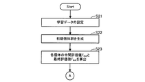
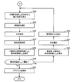
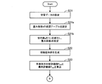
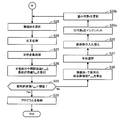
- 11 to 12 are flowcharts showing an example of a program generation processing procedure.
- the learning control unit 121 receives an input operation for setting learning data.
- learning data to be used in this process is specified from the learning data stored in the learning data storage unit 142.
- n sets of learning data are used (where n is an integer of 1 or more).
- the learning control unit 121 generates a plurality of initial individuals by combining the elements registered in the element storage unit 141, and stores the generated initial individuals in the individual group storage unit 143. Since the individual group generated in this process corresponds to the individual group 61 shown in FIG. 3, it will be referred to as “individual group 61” hereinafter.
- Step S23 and the intermediate evaluation value F mid and final evaluation value F last for each individuals included in the population 61 is calculated by the following procedure.
- the learning control unit 121 selects one individual included in the individual group 61 and causes the program execution unit 122 to execute the selected individual.
- the program execution unit 122 executes image processing on each input image included in the n sets of learning data designated in step S21 according to the selected individual. In this image processing, the program execution unit 122 stores an image output at each node of the selected individual in the output image storage unit 144.
- the stored output image includes an intermediate output image output at the intermediate node and a final output image output at the final node. That is, one or more intermediate output images and one final output image are stored for each of the n sets of learning data.
- the learning control unit 121 causes the evaluation value calculation unit 123 to calculate the intermediate evaluation value F mid and the final evaluation value F last for the selected individual.
- the evaluation value calculation unit 123 first calculates a preliminary evaluation value for each intermediate node included in this individual.
- the preliminary evaluation value f (k) of the k-th intermediate node included in this individual is the n intermediate output images output using the n sets of learning data at the k-th intermediate node. And is calculated according to the following equation (1).
- W represents the number of pixels in the horizontal direction of the image
- H represents the number of pixels in the vertical direction of the image.
- m (k, i) (x, y) is a pixel value of coordinates (x, y) in the intermediate output image output at the k th intermediate node, using the input image included in the i th learning data.
- M i (x, y) indicates a pixel value of coordinates (x, y) in the intermediate target image included in the i-th learning data.
- V max indicates the maximum value that the pixel value can take. Note that these pixel values are, for example, luminance values.
- the preliminary evaluation value f (k) takes a value of 0 or more and 1 or less.
- o i (x, y) represents the pixel value of the coordinates (x, y) in the final output image output using the input image included in the i-th learning data.
- T i (x, y) indicates a pixel value of coordinates (x, y) in the final target image included in the i-th learning data.
- the final evaluation value F last takes a value of 0 or more and 1 or less, like the preliminary evaluation value f (k).
- the intermediate evaluation value F mid and final evaluation value F last for each individuals included in the population 61 is calculated.
- the evaluation value calculation unit 123 registers the calculated intermediate evaluation value F mid and the final evaluation value F last in the individual group storage unit 143 in association with the individual.
- the learning control unit 121 instructs the evaluation value calculation unit 123 to calculate the weighting factor t.
- the evaluation value calculation unit 123 calculates the weighting coefficient t based on the distribution status of the intermediate evaluation value F mid of all individuals currently included in the individual group 61. For example, the weighting coefficient t is calculated as an average value of the intermediate evaluation values F mid of all individuals included in the individual group 61.
- the learning control unit 121 randomly selects two parent individuals from the individuals included in the individual group 61.
- the learning control unit 121 generates two or more predetermined number of child individuals by performing crossover between the two selected parent individuals.
- Step S27 The learning control unit 121 causes a mutation in any node of the generated child individual, and the image filter incorporated in the node of the original child individual is registered in the element storage unit 141. Replace with one of the other image filters you have.
- Step S26 an intermediate evaluation value for each child individual generated by the processing of S27 F mid and the final evaluation value F last is intermediate evaluation value F mid and final evaluation value F for individuals in step S23 Calculated in the same procedure as last .
- Step S29 The learning control unit 121 compares the final evaluation value F last for each of the parent individuals selected in step S25 and the child individuals generated in steps S26 and S27 with a predetermined threshold. The learning control unit 121 determines whether there is an individual whose final evaluation value F last is greater than the threshold among these individuals. If there is no individual whose final evaluation value F last is greater than the threshold value, the process of step S30 is executed. If there is an individual whose final evaluation value F last is greater than the threshold, the process of step S33 is executed.
- the learning control unit 121 causes the evaluation value calculation unit 123 to calculate the total evaluation value F total for each of the parent individual selected in step S25 and the child individual generated in steps S26 and S27. .
- the evaluation value calculation unit 123 calculates a comprehensive evaluation value F total for each of these individuals according to the following formula (4).
- F total (1-t) F mid + tF last (4)
- the learning control unit 121 selects the individual having the maximum total evaluation value Ftotal calculated in Step S30 from the parent individual selected in Step S25 and the child individuals generated in Steps S26 and S27. Are selected as surviving individuals. Further, the learning control unit 121 selects one more individual to survive from the remaining individuals. In this selection process, for example, an individual is selected with a probability corresponding to the calculated overall evaluation value F total .
- Step S32 The learning control unit 121 replaces the parent individual selected in Step S25 among the individuals included in the individual group 61 with the two individuals selected in Step S31. As a result, the generation of the individual group 61 is updated. Further, the intermediate evaluation value F mid and the final evaluation value F last for the two individuals selected in step S31 are registered in association with the individual in the individual group storage unit 143.
- At least one of the individuals to be replaced among the individuals included in the individual group 61 may be, for example, an individual having the minimum total evaluation value F total or the final evaluation value F last .
- the learning control unit 121 stores the image processing program corresponding to the individual determined in step S29 that the final evaluation value F last is larger than the threshold value in the program storage unit 130, and ends the processing. If there are a plurality of individuals whose final evaluation value F last is larger than the threshold value in step S29, the learning control unit 121 selects an image processing program corresponding to the individual having the largest final evaluation value F last from among these individuals. Store in the program storage unit 130.
- step S30 the overall evaluation value F total for each individual to be selected for survival is changed to the intermediate evaluation value F mid and the final evaluation value F last for each individual.
- step S31 an individual to be alive is selected based on the comprehensive evaluation value Ftotal .
- step S24 based on the distribution of the intermediate evaluation value F mid for each individual in the population 61 of that generation, the overall evaluation value F total The weighting factor t used for calculation is recalculated. Therefore, the comprehensive evaluation value F total varies with the progress of learning.
- the weighting factor t is calculated based on the distribution state of the intermediate evaluation value Fmid for each individual in the individual group 61, so that the value of the weighting factor t gradually increases as the learning progresses. Go. For this reason, when the comprehensive evaluation value F total is calculated, the synthesis ratio of the final evaluation value F last increases as learning progresses. Thereby, in the initial stage of learning, the individual survival selection is performed with emphasis on the intermediate evaluation value F mid, and as the learning progresses, the individual survival selection is performed with emphasis on the final evaluation value F last. become. As the number of individuals having a high intermediate evaluation value F mid increases in the individual group 61, the time until the final evaluation value F last reaches a predetermined threshold is shortened. Therefore, by changing the weighting coefficient as described above, the entire image is obtained. The time until generation of the processing program is completed is shortened.
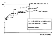
- FIG. 13 is a diagram illustrating an example of changes in the final evaluation value and the weighting factor.
- a comparative example of the change in the value F last is also shown. Note that the final evaluation value F last shown in FIG. 13 is the maximum value among the final evaluation values F last compared with the threshold value in step S29 of FIG.
- the time until the final evaluation value F last exceeds a predetermined threshold in the present embodiment is shortened to about 1 ⁇ 2 compared to the comparative example. Further, the weighting factor t as a whole increases as the number of generations of the individual group 61 increases.
- the second embodiment is configured so as to calculate it according to the temporal progress of learning.
- An example in which is modified is shown. Since the basic configuration of the image processing apparatus according to the third embodiment is the same as that of the second embodiment, description will be made using the same reference numerals as those of the second embodiment.
- FIG. 14 is a diagram for explaining a modulation table used for calculating a weighting factor.
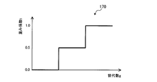
- a graph 170 shown in FIG. 14 is a graph of information registered in the modulation table.
- the weight coefficient t increases in three stages as the generation number g of the individual group 61 increases.
- the image processing apparatus 100 calculates the weighting factor t based on a modulation table that stores the correspondence between the generation number g and the weighting factor t as shown in the graph 170.
- the calculation of the weighting factor t is not limited to the method using the modulation table as long as the weighting factor t increases as the learning progresses.
- the weighting factor t may be calculated using a predetermined calculation formula.
- FIG. 15 to 16 are flowcharts showing an example of a program generation processing procedure in the third embodiment.
- processing steps in which processing similar to that in FIG. 11 to FIG. 12 is performed are denoted by the same step numbers and description thereof is omitted.
- Steps S21a and S21b are added between step S21 and step S22. Further, the process of step S24 is deleted, and step S25 is executed after step S23. Further, steps S32a and S32b are added after step S32, and step S25 is executed after step S32b.
- the learning control unit 121 sets a modulation table for the weighting factor t. For example, the correspondence between the generation number g and the weighting factor t is set by a user input operation. [Step S ⁇ b> 21 b] The learning control unit 121 initializes the generation number g to 1, and instructs the evaluation value calculation unit 123 to set the weighting factor t. The evaluation value calculation unit 123 sets the value of the weighting factor t associated with the current generation number g with reference to the modulation table.
- Step S32a The learning control unit 121 increments the generation number g by one.
- Step S32b The learning control unit 121 instructs the evaluation value calculation unit 123 to update the weighting coefficient t.
- the evaluation value calculation unit 123 refers to the modulation table and updates the set value of the current weighting factor t using the value of the weighting factor t associated with the current generation number g.
- step S21b may be executed at any timing after the end of step S21a and before the execution of step S30. Further, the processes of steps S32a and S32b may be executed at any timing after the end of step S32 and before the execution of the next step S30.
- the value of the weighting factor t gradually increases as the learning progresses.
- the processing functions of the devices (the program generation device 1 and the image processing device 100) described in each of the above embodiments can be realized by a computer.
- a program describing the processing contents of the functions that each device should have is provided, and the processing functions are realized on the computer by executing the program on the computer.
- the program describing the processing contents can be recorded on a computer-readable recording medium.
- the computer-readable recording medium include a magnetic storage device, an optical disk, a magneto-optical recording medium, and a semiconductor memory.
- Examples of the magnetic storage device include a hard disk device (HDD), a flexible disk (FD), and a magnetic tape.
- Optical discs include DVD (Digital Versatile Disc), DVD-RAM, CD-ROM (Compact Disc-Read Only Memory), CD-R (Recordable) / RW (ReWritable), and the like.
- Magneto-optical recording media include MO (Magneto-Optical disk).
- a portable recording medium such as a DVD or CD-ROM in which the program is recorded is sold. It is also possible to store the program in a storage device of a server computer and transfer the program from the server computer to another computer via a network.
- the computer that executes the program stores, for example, the program recorded on the portable recording medium or the program transferred from the server computer in its own storage device. Then, the computer reads the program from its own storage device and executes processing according to the program. The computer can also read the program directly from the portable recording medium and execute processing according to the program. In addition, each time a program is transferred from a server computer connected via a network, the computer can sequentially execute processing according to the received program.
Landscapes
- Engineering & Computer Science (AREA)
- Theoretical Computer Science (AREA)
- Physics & Mathematics (AREA)
- General Physics & Mathematics (AREA)
- Software Systems (AREA)
- Health & Medical Sciences (AREA)
- Life Sciences & Earth Sciences (AREA)
- General Engineering & Computer Science (AREA)
- Biophysics (AREA)
- Evolutionary Computation (AREA)
- Artificial Intelligence (AREA)
- Multimedia (AREA)
- Evolutionary Biology (AREA)
- Bioinformatics & Cheminformatics (AREA)
- Bioinformatics & Computational Biology (AREA)
- Data Mining & Analysis (AREA)
- General Health & Medical Sciences (AREA)
- Computing Systems (AREA)
- Computer Vision & Pattern Recognition (AREA)
- Mathematical Physics (AREA)
- Molecular Biology (AREA)
- Genetics & Genomics (AREA)
- Computational Linguistics (AREA)
- Biomedical Technology (AREA)
- Databases & Information Systems (AREA)
- Medical Informatics (AREA)
- Physiology (AREA)
- Image Analysis (AREA)
- Image Processing (AREA)
- Stored Programmes (AREA)
Abstract
遺伝的プログラミングによって画像処理プログラムを生成する際の生存選択を適正化する。 演算部(1b)は、それぞれ複数の部分プログラムが組み合わされた複数の画像処理プログラム(21,22,23,・・・)の中から画像処理プログラム(21)を選択し、画像処理プログラム(21)に含まれる部分プログラムの一部を変更することで画像処理プログラム(21a)を生成し、画像処理プログラム(21a)を用いて入力画像(11)に対する画像処理を実行し、画像処理の途中で出力される中間出力画像(31,32)と第1目標画像(12)との比較に基づいて、画像処理プログラム(21a)を次世代に残すかを判定し、次世代に残すと判定された場合、画像処理プログラム(21,22,23,・・・)の1つを画像処理プログラム(21a)に入れ替える。
Description
本発明は、プログラム生成装置、プログラム生成方法および生成プログラムに関する。
所望の画像処理を実行する画像処理プログラムを、遺伝的プログラミングによって自動生成する技術が注目されている。この技術は、入力画像と処理結果の画像(目標画像)の組といった学習データを用いて、画像処理のための部分プログラム(例えば、画像フィルタのプログラム)を組み合わせて生成される画像処理プログラムを、遺伝的プログラミングによって最適化していくものである。
また、遺伝的プログラミングを利用した装置の例として、現世代の重みデータと、前世代以前の世代で利用した重みデータとを用いて変換器を進化させるようにした遺伝的処理装置が提案されている。
青木紳也、長尾智晴、「木構造画像変換の自動構築法ACTIT」、情報メディア学会誌Vol.53,No.6、1999年6月20日、p.890-892
遺伝的プログラミングによって画像処理プログラムを自動生成する処理では、例えば、次のような生存選択方法が用いられる。学習の過程で生成された個体に対応するプログラムを用いて、学習データに含まれる入力画像が処理される。その処理結果として出力された出力画像が学習データに含まれる目標画像と比較され、その比較結果に基づいて個体を次世代に残すかが判定される。
しかし、この方法では、画像処理の内容によっては、学習が促進されるような有用な固体が淘汰されてしまう場合があるという問題がある。このような問題は、画像処理プログラムの生成処理に長い時間がかかってしまう原因になり得る。
1つの側面では、本発明は、遺伝的プログラミングによって画像処理プログラムを生成する際の生存選択を適正化することが可能なプログラム生成装置、プログラム生成方法および生成プログラムを提供することを目的とする。
1つの案では、遺伝的プログラミングによってプログラムを生成するプログラム生成装置が提供される。このプログラム生成装置は、記憶部と演算部とを有する。記憶部は、入力画像と第1目標画像とを含む学習データを記憶する。ここで、第1目標画像は、入力画像を第2目標画像に変換する処理の途中で出力される画像を示す。演算部は、それぞれ複数の部分プログラムが組み合わされた複数の画像処理プログラムの中から第1プログラムを選択し、第1プログラムに含まれる部分プログラムの一部を変更することで第2プログラムを生成し、第2プログラムを用いて入力画像に対する画像処理を実行し、画像処理の途中で出力される中間出力画像と第1目標画像との比較に基づいて、第2プログラムを次世代に残すかを判定し、第2プログラムを次世代に残すと判定された場合、複数の画像処理プログラムの1つを第2プログラムに入れ替える。
また、1つの案では、上記のプログラム生成装置と同様の処理をコンピュータが実行するプログラム生成方法が提供される。
さらに、1つの案では、上記のプログラム生成装置と同様の処理をコンピュータに実行させる生成プログラムが提供される。
さらに、1つの案では、上記のプログラム生成装置と同様の処理をコンピュータに実行させる生成プログラムが提供される。
1つの側面では、遺伝的プログラミングによって画像処理プログラムを生成する際の生存選択を適正化できる。
本発明の上記および他の目的、特徴および利点は本発明の例として好ましい実施の形態を表す添付の図面と関連した以下の説明により明らかになるであろう。
本発明の上記および他の目的、特徴および利点は本発明の例として好ましい実施の形態を表す添付の図面と関連した以下の説明により明らかになるであろう。
以下、本発明の実施の形態について図面を参照して説明する。
〔第1の実施の形態〕
図1は、第1の実施の形態に係るプログラム生成装置の構成例および処理例を示す図である。プログラム生成装置1は、遺伝的プログラミングによって画像処理プログラムを生成する装置である。
〔第1の実施の形態〕
図1は、第1の実施の形態に係るプログラム生成装置の構成例および処理例を示す図である。プログラム生成装置1は、遺伝的プログラミングによって画像処理プログラムを生成する装置である。
プログラム生成装置1は、記憶部1aと演算部1bとを有する。記憶部1aは、例えば、RAM(Random Access Memory)などの揮発性記憶装置、または、HDD(Hard Disk Drive)、フラッシュメモリなどの不揮発性記憶装置として実装される。演算部1bは、例えば、プロセッサである。
記憶部1aは、学習データ10を記憶する。学習データ10は、入力画像11、第1目標画像12および第2目標画像13を含む。第2目標画像13は、入力画像11に画像処理を施した場合に、その処理結果として出力される画像の目標となる画像である。一方、第1目標画像12は、入力画像11を第2目標画像13に変換するような画像処理を施した場合に、その画像処理の途中のどこかの段階で出力される画像の目標となる画像である。例えば、入力画像11における特定の画像領域に特定の処理を施すという画像処理の場合、第1目標画像12としては、画像におけるその特定の画像領域と、それ以外の画像領域(背景領域)とが区別された画像を用いることができる。各画像領域は、例えば、特定の画像領域の画素値を最大値とし、背景画像領域の画素値を最小値(0)とするなど、画素値の割り当てによって区別させることができる。
なお、記憶部1aには、複数組の学習データ10が記憶されてもよい。
また、記憶部1aは、プログラム群20を記憶してもよい。プログラム群20は、演算部1bの処理で利用されるデータであり、複数の画像処理プログラム21,22,23,・・・を含む。プログラム群20に含まれる画像処理プログラム21,22,23,・・・は、それぞれ、複数の部分プログラムが組み合わされて生成される。部分プログラムは、画像フィルタなどの画像処理を実行するためのプログラム部品である。プログラム生成装置1は、プログラム群20の世代が更新されるたびに、プログラム群20に適応度の高い画像処理プログラムを優先的に残存させることによって、所望の画像処理を実行する画像処理プログラムを生成する。
また、記憶部1aは、プログラム群20を記憶してもよい。プログラム群20は、演算部1bの処理で利用されるデータであり、複数の画像処理プログラム21,22,23,・・・を含む。プログラム群20に含まれる画像処理プログラム21,22,23,・・・は、それぞれ、複数の部分プログラムが組み合わされて生成される。部分プログラムは、画像フィルタなどの画像処理を実行するためのプログラム部品である。プログラム生成装置1は、プログラム群20の世代が更新されるたびに、プログラム群20に適応度の高い画像処理プログラムを優先的に残存させることによって、所望の画像処理を実行する画像処理プログラムを生成する。
演算部1bは、プログラム群20から画像処理プログラムを選択する(ステップS1)。ここでは例として、画像処理プログラム21が選択されたものとする。次に、演算部1bは、選択した画像処理プログラム21に含まれる部分プログラムの一部を変更することで、画像処理プログラム21aを生成する。この処理過程は、画像処理プログラム21を進化させる過程である(ステップS2)。この進化過程では、例えば、画像処理プログラム21と、プログラム群20から選択された他の画像処理プログラムとの間の交叉や、画像処理プログラム21またはその交叉後のプログラムの突然変異などが行われる。
進化過程により、例えば、部分プログラムP1~P3が組み合わされた画像処理プログラム21aが生成されたとする。なお、図1中の「In」は、画像処理プログラム21aの入力部を示し、「Out」は、画像処理プログラム21aの出力部を示す。
次に、演算部1bは、画像処理プログラム21aを用いて、入力画像11に対する画像処理を実行する(ステップS3)。演算部1bは、この画像処理の途中で中間出力画像を出力する。例えば、中間出力画像は、画像処理プログラム21aに含まれる部分プログラムP1~P3のうち、最終段に組み込まれた部分プログラムP3を除く部分プログラムP1,P2のそれぞれの処理結果として出力される画像である。図1の例では、部分プログラムP1の処理結果として中間出力画像31が出力され、部分プログラムP2の処理結果として中間出力画像32が出力される。
次に、演算部1bは、生成された画像処理プログラム21aを次世代に残すかを判定する(ステップS4)。このステップS4の処理は、中間出力画像31,32と第1目標画像12とを比較する処理(ステップS4a)を含む。このステップS4aでは、例えば、画像間の類似度が比較結果として出力される。また、図1の例のようにステップS4aで複数の中間出力画像31,32と第1目標画像12とが比較される場合、その比較結果としては、例えば、中間出力画像31,32と第1目標画像12との各類似度の最大値が出力される。演算部1bは、ステップS4aでの比較結果に基づいて、画像処理プログラム21aを次世代に残すかを判定する。
なお、ステップS4では、ステップS4aでの比較結果だけでなく、画像処理プログラム21aの実行結果として出力される最終出力画像と、第2目標画像13との比較結果を用いて、判定が行われてもよい。
ステップS4において画像処理プログラム21aを次世代に残すと判定された場合、演算部1bは、プログラム群20に含まれる画像処理プログラム21,22,23,・・・の1つを、画像処理プログラム21aに入れ替える(ステップS5)。これにより、プログラム群20の世代が更新される。
ここで、画像処理プログラム21aを次世代に残すかの判定方法としては、画像処理プログラム21aによる画像処理の結果として出力される最終出力画像と、第2目標画像13との比較に基づいて判定する方法が考えられる。しかし、この方法では、画像処理の途中で、第1目標画像12のような所望の画像に近い画像が生成されていたとしても、最終画像と第2目標画像13とが類似していなければ、画像処理プログラム21aは淘汰され、次世代のプログラム群20に残らない。このように、学習の促進に役立つ可能性の高い有効な画像処理プログラムが淘汰されてしまうことが、画像処理プログラムの生成が完了するまでにかかる時間を長くする原因となり得る。
これに対して、ステップS4aでの比較結果は、画像処理プログラム21aの実行途中で出力される中間出力画像が、所望の画像に近いかの指標を示す。ステップS4においてこのような指標に基づいて判定が行われることで、画像処理プログラム21aの実行途中で適切な画像を出力できる可能性の高い画像処理プログラムが、淘汰されずに次世代のプログラム群20に残存するようになる。これにより、処理過程が適切と指定される画像処理プログラムが次世代に残りやすくなるように、生存選択が適正化される。
そして、上記手順で世代が更新されたプログラム群20を用いてステップS1~S5の処理が繰り返し実行されることで、ステップS4aでの比較結果が示す画像間の近さの度合いが上昇する速度が速まっていき、学習速度が向上する。これにより、プログラム群20に含まれる画像処理プログラム、および、それらの画像処理プログラムから進化過程によって生成された画像処理プログラムの適応度の最大値が、所定の閾値に達するまでの時間が短くなる。すなわち、所望の処理を実現する画像処理プログラムが生成されるまでの時間が短縮される。
〔第2の実施の形態〕
次に、第2の実施の形態に係る画像処理装置について説明する。第2の実施の形態に係る画像処理装置は、図1に示したプログラム生成装置1と同様の処理機能と、この処理機能によって生成された画像処理プログラムを実行して画像処理を行う機能とを備える。
次に、第2の実施の形態に係る画像処理装置について説明する。第2の実施の形態に係る画像処理装置は、図1に示したプログラム生成装置1と同様の処理機能と、この処理機能によって生成された画像処理プログラムを実行して画像処理を行う機能とを備える。
以下の説明では、まず、図2~図4を用いて、遺伝的プログラミングによる画像処理プログラムの生成処理の基本的な手順を示す比較例について説明し、図5を用いて、比較例における問題点について説明する。そして、その後に第2の実施の形態に係る画像処理装置について説明する。
図2は、画像処理プログラムの生成処理手順の比較例を示す図である。
画像処理プログラムの生成処理の前に、1つ以上の学習データ50が用意される。学習データ50には、入力画像51と、入力画像51に対して画像処理を施したときの目標画像52とが含まれる。入力画像51は、例えば、カメラによって被写体を撮像することによって得られる。
画像処理プログラムの生成処理の前に、1つ以上の学習データ50が用意される。学習データ50には、入力画像51と、入力画像51に対して画像処理を施したときの目標画像52とが含まれる。入力画像51は、例えば、カメラによって被写体を撮像することによって得られる。
遺伝的プログラミングによる画像処理プログラムの生成処理では、個体は、1つ以上の部分プログラムを組み合わせて構成される。例えば、図2の左上に示すように、個体は木構造で定義される。
個体に組み込むことが可能な複数の部分プログラムも、あらかじめ用意される。以下、個体に組み込まれる部分プログラムの例として、画像フィルタを想定するが、部分プログラムは画像フィルタに限るものではなく、他の種類の画像処理を行うプログラムを用いることもできる。なお、図2の左上において、“F”は画像フィルタを示し、“I”は入力端子を示し、“O”は出力端子を示す。
遺伝的プログラミングによる画像処理プログラムの生成処理は、例えば、次のように実行される。まず、複数の初期個体による個体群61が生成される(ステップS11)。各初期個体のノードには、あらかじめ用意された複数の画像フィルタの中から画像フィルタがランダムに選択されて組み込まれる。次に、生成された個体群61の中から、ランダムに2つの親個体が取り出される(ステップS12)。
次に、これら2つの親個体に対して進化過程の処理が施されることで、2つ以上の子個体が生成される(ステップS13)。進化過程では、2つの親個体に対して交叉処理および突然変異処理が行われる。2つの親個体に対して、それぞれ異なる交叉処理や突然変異処理が行われることで、3つ以上の子個体が生成されてもよい。
次に、進化過程を経て生成された子個体、および元の親個体のそれぞれについて、適応度が計算される(ステップS14)。この処理では、対象の個体それぞれを用いた画像処理が、学習データ50の入力画像51に対して実行され、実行後の画像と対応する目標画像52とが比較されることで適応度が計算される。複数の学習データ50が存在する場合、個体それぞれについて、複数の学習データ50を用いて得られた適応度の平均値が算出される。
ここで、いずれかの個体の適応度が所定の閾値以上であった場合には、その個体が最終的な画像処理プログラムとして出力され、プログラム生成処理が終了する。一方、すべての個体の適応度が所定の閾値未満であった場合には、生成された各子個体および元の2つの親個体を含む個体群62の中から、生存選択が行われる(ステップS15)。この生存選択では、個体群62の中から、算出された適応度が最大の個体が選択される。さらに、個体群62内の残りの個体の中から、所定の方法で個体が1つ選択される。例えば、残りの個体の中から、適応度に応じた確率で個体が選択される。
このような生存選択によって選択された2つの個体は、個体群61に含まれる2つの個体と入れ替えられる(ステップS16)。例えば、生存選択によって選択された2つの個体は、個体群61に含まれる個体のうち、親個体として取り出された2つの個体と入れ替えられる。これにより、個体群61に含まれる個体が次世代の個体へ変更される。そして、適応度が所定の閾値以上となる個体が出現するまで、同様の処理が繰り返される。
図3は、交叉の例を示す図である。図3では、親個体71aと親個体72aとの間で交叉が行われ、親個体71aに基づく子個体71bと、親個体72aに基づく子個体72bとが生成される場合の例を示す。
親個体71aは、画像フィルタF1,F2,F3,F4を含み、親個体72aは、画像フィルタF2,F3,F5,F6を含む。ここで、親個体71aにおける画像フィルタF2のノードと、親個体72aにおける画像フィルタF5のノードが、交叉を行う箇所として選択されたものとする。
交叉の処理では、例えば、選択されたノードだけでなく、そのノードより下位階層のノードも交叉の対象となる。このため、図3の例では、親個体71aにおける“画像フィルタF2,F1、画像フィルタF2の一方に接続された入力端子のノード、画像フィルタF1に接続された入力端子のノード”と、親個体72aにおける“画像フィルタF5、画像フィルタF5に接続された入力端子のノード”とが入れ替えられる。このような交叉により、画像フィルタF3,F4,F5を含む子個体71bと、画像フィルタF1,F2,F4をそれぞれ1つ含み、画像フィルタF3を2つ含む子個体72bとが生成される。
図4は、突然変異の例を示す図である。図4において、個体73aは、画像フィルタF3,F4,F5を含む。この個体73aは、例えば、個体群61から取り出された親個体であってもよいし、または、個体群61から親個体として取り出された後、交叉が行われた個体であってもよい。
ここで、個体73aにおける画像フィルタF3のノードが突然変異を行う箇所として選択されるとともに、突然変異による置き換え後の画像フィルタとして画像フィルタF7が選択されたものとする。なお、突然変異による置き換え後の画像フィルタは、あらかじめ用意された複数の画像フィルタの中からランダムに選択される。このような突然変異により、画像フィルタF4,F5,F7を含む子個体73bが生成される。
ところで、上記の手順により生成される画像処理プログラムの用途の例としては、FA(Factory Automation)分野において、製品を撮像した画像に画像処理を施して所望の効果を得るという用途が考えられる。例えば、製品の外観を撮像した画像に画像処理を施して、欠陥が生じた箇所を抽出する、位置合わせを行う箇所を抽出する、特定の部品に印字された文字を認識するといった用途が考えられる。
このような用途では、被写体となる製品の変更や改良、それに伴う撮像環境の変化などに応じて、画像処理アルゴリズムの再構築の必要が生じる場合がある。このため、画像処理アルゴリズムの構築の容易性が求められている。また、照明条件の変化や被写体の形状、位置姿勢のばらつき等の撮像環境の変化に対するロバスト性が高い画像処理アルゴリズムを構築することが求められている。
遺伝的プログラミングを利用することで、入力画像51とこれに対応する目標画像52とをあらかじめ用意しておくだけで、このような用途で使用可能な画像処理プログラムを容易に生成することができる。また、それぞれ撮像環境が異なる入力画像51と目標画像52のペア(学習データ50)を複数用意しておくことで、撮像環境の変化に対するロバスト性が高い画像処理アルゴリズムを自動生成することもできる。
ここで、図5は、画像処理の例を示す図である。画像処理の例として、入力画像内の特定の領域について何らかの特定の処理を施すというものがある。図5では、その一例として、プリント基板に搭載された半導体チップのパッケージ領域から、その領域に印字された文字の部分だけを特定の色(例えば、白)の領域として抽出する処理を示す。画像処理の結果として最終的に出力される最終出力画像81dにおいては、半導体チップのパッケージ領域に印字された「ABC123」という文字の部分だけが白の領域として抽出されている。
なお、図5の画像処理は、例えば、特定の領域から文字を認識するための前処理として実行される。また、特定の領域について何らかの処理を施すという処理の他の例としては、特定の部品が搭載された領域から、部品に描かれた記号や模様の部分を特定の色の領域として抽出する処理が考えられる。さらに、また、画像内の特定の領域における部品の位置や傾きを検出するために、その領域における部品の搭載領域だけを特定の色の領域として抽出する、という処理も考えられる。
以下、文字や記号、模様の抽出対象となる特定の領域を、「抽出対象領域」と記載する。
上記のような画像処理における入力画像については、撮影時における被写体の明るさが画像ごとに大きくばらつく可能性がある。それだけでなく、画像内の抽出対象領域の明るさのばらつき度合いと、その領域以外の背景領域の明るさのばらつき度合いとが異なることも多い。それは、抽出対象領域と背景領域とで明るさのばらつきの発生原因が異なる場合があるからである。例えば、抽出対象領域と背景領域とで光の反射率や色の傾向が異なることや、抽出対象領域と背景領域の高さの差によって周囲からの光の当たり方が異なることが、原因となり得る。
上記のような画像処理における入力画像については、撮影時における被写体の明るさが画像ごとに大きくばらつく可能性がある。それだけでなく、画像内の抽出対象領域の明るさのばらつき度合いと、その領域以外の背景領域の明るさのばらつき度合いとが異なることも多い。それは、抽出対象領域と背景領域とで明るさのばらつきの発生原因が異なる場合があるからである。例えば、抽出対象領域と背景領域とで光の反射率や色の傾向が異なることや、抽出対象領域と背景領域の高さの差によって周囲からの光の当たり方が異なることが、原因となり得る。
このため、画像全体に対する処理によって明るさのばらつきの影響を低減するような前処理のアルゴリズムを構築することは、難易度が高い。明るさのばらつきの影響を低減するためには、抽出対象領域と背景領域のそれぞれに対して別々の前処理を施すことが望ましい。このような理由から、上記のような画像処理におけるロバスト性を向上させるためには、抽出対象領域と背景領域との切り分け処理を含めることが重要となる。
図5に示す入力画像81aにおいては、半導体チップのパッケージ領域は黒色であるため、照明の変動に対する輝度の変化は小さい。しかし、背景となるプリント基板はより明るい色であるため、照明の変動に対する輝度の変化が大きくなる可能性がある。このような被写体が写った入力画像81aから最終出力画像81dが得られるような画像処理プログラムをプログラマーが構築する場合、半導体チップのパッケージ領域を抽出するような中間処理アルゴリズムを含めることが多い。この中間処理アルゴリズムによれば、例えば、抽出された領域とそれ以外の背景領域とが画素値などによって区別された画像が得られる。そして、得られた画像を用いて文字の領域が抽出される。
このように、抽出された領域とそれ以外の背景領域とが区別された画像の例としては、抽出された領域以外の背景領域をマスクしたマスク画像がある。マスク画像では、抽出された領域が白領域(すなわち、画素値が最大値の領域)とされ、それ以外の背景領域が黒領域(すなわち、画素値が最小値の領域)とされる。
図5に示す中間出力画像81bは、上記のような中間処理アルゴリズムによって生成されたマスク画像の一例である。この中間処理アルゴリズムは、例えば、入力画像81aから半導体チップのパッケージ領域と類似する色の領域を抽出するものである。他方、図5に示す画像処理は、例えば、抽出する文字と類似する色の領域を入力画像81aから抽出する処理も含む。図5に示す中間出力画像81cは、このような処理によって得られた画像の例である。そして、図5に示す画像処理では、中間処理画像81bと中間処理画像81cとの論理積(and)をとることで、最終出力画像81dが生成される。
このような画像処理を実行するための画像処理プログラムを、図2に示した手順によって生成した場合、生存選択のための個体の評価(すなわち、適応度の算出)は、最終出力画像81dとこれに対応する目標画像との比較によって行われることになる。この場合、個体を用いた画像処理の実行途中で抽出対象領域を抽出できるような有効な処理が実行されていたとしても、そのことに関係なく、最終的な出力画像に基づく評価結果によって個体が淘汰される。このため、画像処理の実行途中で有効な出力が得られている個体を次世代に残すことができないという問題がある。
このことは、最終的な出力画像に基づく評価結果だけを用いて個体の生存選択を行うと、その評価結果を示す値が収束するまでに時間がかかり、画像処理プログラムの生成に要する時間が長くなることの1つの原因となることを示す。換言すると、最終的な出力画像だけでなく、画像処理の実行途中で得られる中間出力画像も加味した評価結果に基づいて生存選択を行うことにより、画像処理プログラムの生成時間を短縮できる可能性がある。
なお、上記の問題を解決するための他の方法として、入力画像上に抽出対象領域に対応する関心領域(Region Of Interest:ROI)を事前に設定した上で、画像処理プログラムを生成する方法も考えられる。しかし、この方法は、抽出対象領域が決まった場所に存在する画像に対する画像処理にしか適用できない。また、他の方法として、関心領域の抽出処理を行うプログラムの学習と、それ以後の処理を行うプログラムの学習とを個別に行う方法も考えられる。しかし、複数回の学習を行うことで全体のプログラム生成時間が長くなってしまう。
図6は、第2の実施の形態における個体の評価手順の概要を示す図である。本実施の形態の画像処理装置は、図6に示すような手順で個体を評価する。
本実施の形態では、学習データ82として、入力画像82aと中間目標画像82bと最終目標画像82cとの組み合わせが用意される。最終目標画像82cは、評価対象の個体を用いた画像処理によって最終的に出力される画像についての目標画像である。中間目標画像82bは、評価対象の個体を用いた画像処理の途中の段階、すなわち、その個体の最終ノードを除くいずれかのノードにおいて出力される画像についての目標画像である。図6の例では、中間目標画像82bは、抽出対象領域以外の領域(背景領域)をマスクするためのマスク画像である。
本実施の形態では、学習データ82として、入力画像82aと中間目標画像82bと最終目標画像82cとの組み合わせが用意される。最終目標画像82cは、評価対象の個体を用いた画像処理によって最終的に出力される画像についての目標画像である。中間目標画像82bは、評価対象の個体を用いた画像処理の途中の段階、すなわち、その個体の最終ノードを除くいずれかのノードにおいて出力される画像についての目標画像である。図6の例では、中間目標画像82bは、抽出対象領域以外の領域(背景領域)をマスクするためのマスク画像である。
図6では、評価対象の個体の例として、画像フィルタF1~F9を有する個体74を示している。本実施の形態の画像処理装置は、入力画像82aを入力として、評価対象の個体74を用いた画像処理を実行する。そして、画像処理装置は、個体74において画像フィルタ(部分プログラム)が組み込まれている各ノードで出力される出力画像を取得する。
取得される出力画像には、最終ノードを除く各ノード(中間ノード)で出力される中間出力画像83a,83b,83c,・・・と、最終ノードで出力される最終出力画像84とに大別される。すなわち、画像処理装置は、個体74の最終ノードに組み込まれた画像フィルタF9を除く他の画像フィルタF1~F9からの出力画像を、中間出力画像83a,83b,83c,・・・として取得する。また、画像処理装置は、個体74の最終ノードに組み込まれた画像フィルタF9からの出力画像(すなわち、個体74の最終的な出力画像)を、最終出力画像84として取得する。
画像処理装置は、取得した最終出力画像84と最終目標画像82cとの比較結果に加え、取得した中間出力画像83a,83b,83c,・・・のそれぞれと中間目標画像82bとの比較結果に基づいて、個体74を次世代に残すか否かを判定する。
より具体的には、画像処理装置は、取得した最終出力画像84と最終目標画像82cとを比較し、その比較結果に基づいて最終評価値85bを算出する。この算出方法は図2のステップS14と同様の方法とすることができ、例えば、最終出力画像84と最終目標画像82cとの類似度が最終評価値85bとして算出される。
これに加え、画像処理装置は、取得した中間出力画像83a,83b,83c,・・・のそれぞれを、中間目標画像82bと比較し、その比較結果に基づいて中間評価値85aを算出する。例えば、画像処理装置は、中間出力画像83a,83b,83c,・・・のそれぞれと中間目標画像82bとの類似度を算出し、算出された類似度のうちの最大値を中間評価値85aとする。
そして、画像処理装置は、中間評価値85aと最終評価値85bとに基づいて、個体74を次世代に残すか否かを判定する。例えば、中間評価値85aと最終評価値85bとを重み係数に応じた比率で合成した評価値に基づいて、個体74を次世代に残すか否かを判定する。
このような手順により、最終出力画像が目標とする最終画像に近いだけでなく、いずれかの中間出力画像が目標とする中間画像に近い個体が、次世代に残るようになる。個体群61(図2参照)において、このように中間出力画像が中間目標画像に近いと推定される個体が増えていくことにより、個体群61から生成される親個体および子個体の最終評価値が上昇しやすくなり、学習が促進される。その結果、画像処理プログラムの生成が完了するまでの時間が短縮される。
また、画像処理装置は、個体を次世代に残すかを判定するための評価値として、中間評価値と最終評価値とに重み付けを行って算出した値を用いることもできる。例えば、画像処理装置は、学習の初期段階では、中間評価値の重みを大きくして算出した評価値を用い、学習が進むに連れて、評価値を算出する際の最終評価値の重みを徐々に大きくしていく。これにより、学習の初期段階では、中間出力画像が中間目標画像に近づくことが重視されるように学習が行われる。そして、学習が進んで中間評価値が収束していくと、最終出力画像が最終目標画像に近づくことが重視されるようになる。個体群61に中間評価値の高い個体が多くなるほど、最終評価値が所定の閾値に達するまでの時間が短縮されるので、上記のように重みを変化させることで全体として画像処理プログラムの生成が完了するまでの時間が短縮される。
次に、第2の実施の形態の画像処理装置の詳細について説明する。
図7は、画像処理装置のハードウェア構成例を示す図である。画像処理装置100は、例えば、図7に示すようなコンピュータとして実現される。
図7は、画像処理装置のハードウェア構成例を示す図である。画像処理装置100は、例えば、図7に示すようなコンピュータとして実現される。
画像処理装置100は、プロセッサ101によって装置全体が制御されている。プロセッサ101は、マルチプロセッサであってもよい。プロセッサ101は、例えばCPU(Central Processing Unit)、MPU(Micro Processing Unit)、DSP(Digital Signal Processor)、ASIC(Application Specific Integrated Circuit)、またはPLD(Programmable Logic Device)である。また、プロセッサ101は、CPU、MPU、DSP、ASIC、PLDのうちの2以上の要素の組み合わせであってもよい。
プロセッサ101には、バス109を介して、RAM(Random Access Memory)102と複数の周辺機器が接続されている。
RAM102は、画像処理装置100の主記憶装置として使用される。RAM102には、プロセッサ101に実行させるOS(Operating System)プログラムやアプリケーションプログラムの少なくとも一部が一時的に格納される。また、RAM102には、プロセッサ101による処理に必要な各種データが格納される。
RAM102は、画像処理装置100の主記憶装置として使用される。RAM102には、プロセッサ101に実行させるOS(Operating System)プログラムやアプリケーションプログラムの少なくとも一部が一時的に格納される。また、RAM102には、プロセッサ101による処理に必要な各種データが格納される。
バス109に接続されている周辺機器としては、HDD103、グラフィック処理装置104、入力インタフェース105、読み取り装置106、ネットワークインタフェース107および通信インタフェース108がある。
HDD103は、画像処理装置100の補助記憶装置として使用される。HDD103には、OSプログラム、アプリケーションプログラム、および各種データが格納される。なお、補助記憶装置としては、SSD(Solid State Drive)などの他の種類の不揮発性記憶装置を使用することもできる。
グラフィック処理装置104には、表示装置104aが接続されている。グラフィック処理装置104は、プロセッサ101からの命令にしたがって、画像を表示装置104aの画面に表示させる。表示装置としては、液晶ディスプレイや有機EL(ElectroLuminescence)ディスプレイなどがある。
入力インタフェース105には、入力装置105aが接続されている。入力インタフェース105は、入力装置105aから出力される信号をプロセッサ101に送信する。入力装置105aとしては、キーボードやポインティングデバイスなどがある。ポインティングデバイスとしては、マウス、タッチパネル、タブレット、タッチパッド、トラックボールなどがある。
読み取り装置106には、可搬型記録媒体106aが脱着される。読み取り装置106は、可搬型記録媒体106aに記録されたデータを読み取ってプロセッサ101に送信する。可搬型記録媒体106aとしては、光ディスク、光磁気ディスク、半導体メモリなどがある。
ネットワークインタフェース107は、ネットワーク107aを介して他の装置との間でデータの送受信を行う。
通信インタフェース108は、接続された外部デバイスとの間でデータの送受信を行う。本実施の形態では、通信インタフェース108には、外部デバイスとしてカメラ108aが接続されており、通信インタフェース108は、カメラ108aから送信された画像データをプロセッサ101に送信する。
通信インタフェース108は、接続された外部デバイスとの間でデータの送受信を行う。本実施の形態では、通信インタフェース108には、外部デバイスとしてカメラ108aが接続されており、通信インタフェース108は、カメラ108aから送信された画像データをプロセッサ101に送信する。
以上のようなハードウェア構成によって、画像処理装置100の処理機能を実現することができる。
図8は、画像処理装置が備える処理機能の構成例を示すブロック図である。画像処理装置100は、画像取得部111、画像処理部112、プログラム生成部120、プログラム記憶部130、要素記憶部141、学習データ記憶部142、個体群記憶部143および出力画像記憶部144を有する。
図8は、画像処理装置が備える処理機能の構成例を示すブロック図である。画像処理装置100は、画像取得部111、画像処理部112、プログラム生成部120、プログラム記憶部130、要素記憶部141、学習データ記憶部142、個体群記憶部143および出力画像記憶部144を有する。
画像取得部111、画像処理部112およびプログラム生成部120の処理は、例えば、画像処理装置100のプロセッサ101が所定のプログラムを実行することで実現される。また、画像処理部112の処理の一部は、プログラム記憶部130に保存された画像処理プログラムを、画像処理装置100のプロセッサ101が実行することで実現される。プログラム記憶部130、要素記憶部141および学習データ記憶部142は、例えば、画像処理装置100のHDD103の記憶領域として実現される。個体群記憶部143および出力画像記憶部144は、例えば、画像処理装置100のRAM102の記憶領域として実現される。
画像取得部111は、撮像された画像のデータをカメラ108aから取得し、プログラム生成部120または画像処理部112に出力する。
プログラム生成部120は、遺伝的プログラミングにより画像処理プログラムを生成し、生成された画像処理プログラムをプログラム記憶部130に保存する。なお、プログラム生成部120の内部構成については後述する。
プログラム生成部120は、遺伝的プログラミングにより画像処理プログラムを生成し、生成された画像処理プログラムをプログラム記憶部130に保存する。なお、プログラム生成部120の内部構成については後述する。
画像処理部112は、カメラ108aによって撮像された画像のデータを画像取得部111を介して取得する。画像処理部112は、プログラム記憶部130に保存された画像処理プログラムにしたがって、取得した画像のデータに画像処理を施す。処理後の画像は、例えば表示装置104aに表示される。
プログラム記憶部130は、プログラム生成部120によって生成された画像処理プログラムを記憶する。
要素記憶部141は、プログラム生成部120によって生成される各個体に組み込むことが可能な要素のデータを記憶する。これらの要素は、画像処理プログラムの構成要素となる部分プログラムであり、例えば、各種の画像フィルタのプログラムが含まれる。
要素記憶部141は、プログラム生成部120によって生成される各個体に組み込むことが可能な要素のデータを記憶する。これらの要素は、画像処理プログラムの構成要素となる部分プログラムであり、例えば、各種の画像フィルタのプログラムが含まれる。
学習データ記憶部142は、入力画像と、これに対応する中間目標画像および最終目標画像の各データを含む学習データを、複数記憶する。学習データに含まれる入力画像は、例えば、画像処理装置100に接続されたカメラ108aによって撮像された画像であってもよい。また、入力画像に対応する中間目標画像および最終目標画像は、例えば、入力画像に対してレタッチ処理を施すことによって作成される。
個体群記憶部143は、個体群を記憶する。個体群は、要素記憶部141に記憶された要素(部分プログラム)を組み合わせることで生成される個体(画像処理プログラム)を複数含む。なお、個体群記憶部143には、各個体に対応する画像処理プログラムそのものが記憶されてもよいし、個体の各ノードに組み込まれた部分プログラム名とノード間の接続構造とを示す構造情報が個体ごとに記憶されてもよい。また、個体群記憶部143には、各個体について算出された評価値が、個体に対応づけて記憶される。
出力画像記憶部144は、生存選択の対象の個体に対応するプログラムの実行によって得られる出力画像を記憶する。この出力画像としては、個体の中間ノードで出力される中間出力画像と、個体の最終ノードで出力される最終出力画像とがある。
プログラム生成部120は、学習制御部121、プログラム実行部122および評価値算出部123を有する。
学習制御部121は、プログラム生成部120でのプログラム生成処理全体を統括的に制御する。例えば、学習制御部121は、初期個体群の生成、個体の進化処理、評価値に基づく生存選択および最終的な画像処理プログラムの出力、生存選択された個体による個体群の更新などの処理を実行する。
学習制御部121は、プログラム生成部120でのプログラム生成処理全体を統括的に制御する。例えば、学習制御部121は、初期個体群の生成、個体の進化処理、評価値に基づく生存選択および最終的な画像処理プログラムの出力、生存選択された個体による個体群の更新などの処理を実行する。
プログラム実行部122は、学習制御部121からの指示に応じて、個体(画像処理プログラム)を実行する。プログラム実行部122は、個体の実行により、その個体の最終ノードで出力される最終出力画像だけでなく、その個体の中間ノードで出力される中間出力画像を出力し、出力画像記憶部144に格納する。
評価値算出部123は、学習制御部121からの指示に応じて、各個体を評価するための評価値を算出する。算出される評価値としては、前述した中間評価値および最終評価値の他、さらに総合評価値がある。
次に、学習データの例について説明する。
図9は、学習データの第1の例を示す図である。図9では、例として、プリント基板に搭載された半導体チップのパッケージ領域から、その領域に印字された文字の部分だけを白色領域として抽出する、という画像処理を想定する。この場合、文字の抽出対象となる抽出対象領域は、半導体チップのパッケージ領域となる。画像処理装置100によってこのような画像処理を実現するための画像処理プログラムを生成する場合には、例えば、図9に示すような学習データ151~153が用いられる。
図9は、学習データの第1の例を示す図である。図9では、例として、プリント基板に搭載された半導体チップのパッケージ領域から、その領域に印字された文字の部分だけを白色領域として抽出する、という画像処理を想定する。この場合、文字の抽出対象となる抽出対象領域は、半導体チップのパッケージ領域となる。画像処理装置100によってこのような画像処理を実現するための画像処理プログラムを生成する場合には、例えば、図9に示すような学習データ151~153が用いられる。
学習データ151は、入力画像151a、中間目的画像151bおよび最終目的画像151cを含む。入力画像151aには、プリント基板が写っている。中間目的画像151bは、入力画像151aにおける半導体チップのパッケージ領域(抽出対象領域)以外の背景領域をマスクしたマスク画像である。最終目的画像151cは、入力画像151aにおける半導体チップのパッケージ領域に印字された文字の部分のみが白色とされた画像である。
学習データ152は、入力画像152a、中間目的画像152bおよび最終目的画像152cを含む。入力画像152aには、プリント基板が写っている。ただし、入力画像152aに写るプリント基板は、入力画像151aに写るプリント基板とは異なるものであってもよいし、入力画像152aにおける半導体チップの搭載位置は、入力画像151aにおける半導体チップの搭載位置とは異なっていてもよい。中間目的画像152bは、入力画像152aにおける背景領域をマスクしたマスク画像である。最終目的画像152cは、入力画像152aにおける半導体チップのパッケージ領域に印字された文字の部分のみが白色とされた画像である。
学習データ153は、入力画像153a、中間目的画像153bおよび最終目的画像153cを含む。入力画像153aには、プリント基板が写っている。ただし、入力画像153aに写るプリント基板は、入力画像151a,152aに写るプリント基板とは異なるものであってもよいし、入力画像153aにおける半導体チップの搭載位置は、入力画像151a,152aにおける半導体チップの搭載位置とは異なっていてもよい。中間目的画像153bは、入力画像153aにおける背景領域をマスクしたマスク画像である。最終目的画像153cは、入力画像153aにおける半導体チップのパッケージ領域に印字された文字の部分のみが白色とされた画像である。
図10は、学習データの第2の例を示す図である。図10では、例として、道路を走行する車両に搭載されたナンバプレート領域から、その領域に印字された文字の部分だけを白色領域として抽出する、という画像処理を想定する。この場合、文字の抽出対象となる抽出対象領域は、ナンバプレート領域となる。画像処理装置100によってこのような画像処理を実現するための画像処理プログラムを生成する場合には、例えば、図10に示すような学習データ161~163が用いられる。
学習データ161は、入力画像161a、中間目的画像161bおよび最終目的画像161cを含む。入力画像161aには、車両が写っている。中間目的画像161bは、入力画像161aにおけるナンバプレート領域(抽出対象領域)以外の背景領域をマスクしたマスク画像である。最終目的画像161cは、入力画像161aにおけるナンバプレート領域に記載された文字の部分のみが白色とされた画像である。
学習データ162は、入力画像162a、中間目的画像162bおよび最終目的画像162cを含む。入力画像162aには、車両が写っている。ただし、入力画像162aに写る車両は、入力画像161aに写る車両とは異なるものであってもよいし、入力画像162aにおけるナンバプレートの位置は、入力画像161aにおけるナンバプレートの位置とは異なっていてもよい。中間目的画像162bは、入力画像162aにおける背景領域をマスクしたマスク画像である。最終目的画像162cは、入力画像162aにおけるナンバプレート領域に印字された文字の部分のみが白色とされた画像である。
学習データ163は、入力画像163a、中間目的画像163bおよび最終目的画像163cを含む。入力画像163aには、車両が写っている。ただし、入力画像163aに写る車両は、入力画像161a,162aに写る車両とは異なるものであってもよいし、入力画像163aにおけるナンバプレートの位置は、入力画像161a,162aにおけるナンバプレートの位置とは異なっていてもよい。中間目的画像163bは、入力画像163aにおける背景領域をマスクしたマスク画像である。最終目的画像163cは、入力画像163aにおけるナンバプレート領域に記載された文字の部分のみが白色とされた画像である。
ここで、上記の図9,図10の例のように、画像処理プログラムの生成時には、抽出対象領域の位置が互いに異なる複数の学習データが利用されることが望ましい。これにより、抽出対象領域が互いに異なる撮像画像を画像処理の対象としても所望の結果を高性能に得ることが可能な画像処理プログラムを生成することができる。
また、図9の入力画像151a,152a,153aでは、撮影時における被写体への照明の明るさが互いに異なっている。また、図10の入力画像161a,162a,163aでは、撮影時における被写体への光の当たり方の分布が互いに異なっている。これらの例のように、画像処理プログラムの生成時には、明るさなどの撮影条件が互いに異なる入力画像を含む複数の学習データが利用されることが望ましい。これにより、撮影条件が変動した場合でも所望の結果を安定的に得ることが可能な画像処理プログラムを生成することができる。
次に、画像処理装置100によるプログラム生成処理の詳細について、フローチャートを用いて説明する。
図11~図12は、プログラム生成処理手順の例を示すフローチャートである。
図11~図12は、プログラム生成処理手順の例を示すフローチャートである。
[ステップS21]学習制御部121は、学習データの設定のための入力操作を受け付ける。例えば、学習データ記憶部142に記憶された学習データの中から、本処理で使用される学習データが指定される。ここでは、n組の学習データが使用されるものとする(ただし、nは1以上の整数)。
[ステップS22]学習制御部121は、要素記憶部141に登録された要素を組み合わせることで、複数の初期個体を生成し、生成された初期個体を個体群記憶部143に格納する。この処理において生成される個体群は図3に示した個体群61に相当するので、これ以後、「個体群61」と表記する。
[ステップS23]個体群61に含まれる各個体についての中間評価値Fmidと最終評価値Flastとが、次のような手順で算出される。
学習制御部121は、個体群61に含まれる個体を1つ選択し、選択した個体をプログラム実行部122に実行させる。プログラム実行部122は、選択された個体にしたがって、ステップS21で指定されたn組の学習データに含まれる各入力画像に対する画像処理を実行する。この画像処理において、プログラム実行部122は、選択した個体の各ノードにおいて出力される画像を出力画像記憶部144に格納する。格納される出力画像には、中間ノードにおいて出力される中間出力画像と、最終ノードにおいて出力される最終出力画像とがある。すなわち、n組の学習データのそれぞれについて、1つ以上の中間出力画像と1つの最終出力画像とが格納される。
学習制御部121は、個体群61に含まれる個体を1つ選択し、選択した個体をプログラム実行部122に実行させる。プログラム実行部122は、選択された個体にしたがって、ステップS21で指定されたn組の学習データに含まれる各入力画像に対する画像処理を実行する。この画像処理において、プログラム実行部122は、選択した個体の各ノードにおいて出力される画像を出力画像記憶部144に格納する。格納される出力画像には、中間ノードにおいて出力される中間出力画像と、最終ノードにおいて出力される最終出力画像とがある。すなわち、n組の学習データのそれぞれについて、1つ以上の中間出力画像と1つの最終出力画像とが格納される。
学習制御部121は、選択した個体についての中間評価値Fmidと最終評価値Flastとを評価値算出部123に算出させる。評価値算出部123は、まず、この個体に含まれる中間ノードごとに予備評価値を算出する。具体的には、この個体に含まれるk番目の中間ノードの予備評価値f(k)は、k番目の中間ノードにおいてn組の学習データをそれぞれ用いて出力されたn個の中間出力画像を用いて、次の式(1)にしたがって算出される。

式(1)において、Wは画像の水平方向の画素数を示し、Hは画像の垂直方向の画素数を示す。m(k,i)(x,y)は、i番目の学習データに含まれる入力画像を用いて、k番目の中間ノードにおいて出力された中間出力画像における座標(x,y)の画素値を示す。Mi(x,y)は、i番目の学習データに含まれる中間目標画像における座標(x,y)の画素値を示す。Vmaxは、画素値がとり得る最大値を示す。なお、これらの画素値は、例えば、輝度値である。式(1)によれば、予備評価値f(k)は0以上1以下の値をとる。
評価値算出部123は、上記の方法で個体に含まれる全中間ノードについての予備評価値f(k)を算出する。そして、評価値算出部123は、次の式(2)にしたがって個体に対応する中間評価値Fmidを算出する。すなわち、個体に対応する中間評価値Fmidは、その個体について算出された各予備評価値f(k)のうちの最大値として算出される。
Fmid=max{f(k)} ・・・(2)
また、評価値算出部123は、個体の最終ノードにおいてn組の学習データをそれぞれ用いて出力されたn個の最終出力画像を用いて、次の式(3)にしたがって最終評価値Flastを算出する。
Fmid=max{f(k)} ・・・(2)
また、評価値算出部123は、個体の最終ノードにおいてn組の学習データをそれぞれ用いて出力されたn個の最終出力画像を用いて、次の式(3)にしたがって最終評価値Flastを算出する。

式(3)において、oi(x,y)は、i番目の学習データに含まれる入力画像を用いて出力された最終出力画像における座標(x,y)の画素値を示す。Ti(x,y)は、i番目の学習データに含まれる最終目標画像における座標(x,y)の画素値を示す。式(3)によれば、最終評価値Flastは、予備評価値f(k)と同様、0以上1以下の値をとる。
以上の手順により、個体群61に含まれる各個体についての中間評価値Fmidと最終評価値Flastとが算出される。評価値算出部123は、算出された中間評価値Fmidと最終評価値Flastとを、個体に対応付けて個体群記憶部143に登録する。
[ステップS24]学習制御部121は、評価値算出部123に重み係数tの算出を指示する。評価値算出部123は、現在個体群61に含まれている全個体の中間評価値Fmidの分布状況に基づいて、重み係数tを算出する。例えば、重み係数tは、個体群61に含まれている全個体の中間評価値Fmidの平均値として算出される。
[ステップS25]学習制御部121は、個体群61に含まれる個体の中から、2つの親個体をランダムに選択する。
[ステップS26]学習制御部121は、選択された2つの親個体の間で交叉を行うことで、2つ以上の所定数の子個体を生成する。
[ステップS26]学習制御部121は、選択された2つの親個体の間で交叉を行うことで、2つ以上の所定数の子個体を生成する。
[ステップS27]学習制御部121は、生成された子個体のいずれかのノードに突然変異を発生させ、元の子個体のノードに組み込まれていた画像フィルタを、要素記憶部141に登録されている他の画像フィルタのいずれかに置き換える。
[ステップS28]ステップS26,S27の処理によって生成された各子個体についての中間評価値Fmidと最終評価値Flastとが、ステップS23での個体についての中間評価値Fmidと最終評価値Flastと同様の手順で算出される。
[ステップS29]学習制御部121は、ステップS25で選択された親個体、および、ステップS26,S27で生成された子個体のそれぞれについての最終評価値Flastと、所定の閾値とを比較する。学習制御部121は、これらの個体の中に、最終評価値Flastが閾値より大きい個体が存在するかを判定する。最終評価値Flastが閾値より大きい個体が存在しない場合、ステップS30の処理が実行される。最終評価値Flastが閾値より大きい個体が存在する場合、ステップS33の処理が実行される。
[ステップS30]学習制御部121は、ステップS25で選択された親個体、および、ステップS26,S27で生成された子個体のそれぞれについての総合評価値Ftotalを、評価値算出部123に算出させる。評価値算出部123は、これらの各個体についての総合評価値Ftotalを、次の式(4)にしたがって算出する。
Ftotal=(1-t)Fmid+tFlast ・・・(4)
[ステップS31]学習制御部121は、ステップS25で選択された親個体、および、ステップS26,S27で生成された子個体の中から、ステップS30で算出された総合評価値Ftotalが最大の個体を、生存させる個体として選択する。さらに、学習制御部121は、残りの個体の中から生存させる個体をさらに1つ選択する。この選択処理では、例えば、算出された総合評価値Ftotalに応じた確率で個体が選択される。
Ftotal=(1-t)Fmid+tFlast ・・・(4)
[ステップS31]学習制御部121は、ステップS25で選択された親個体、および、ステップS26,S27で生成された子個体の中から、ステップS30で算出された総合評価値Ftotalが最大の個体を、生存させる個体として選択する。さらに、学習制御部121は、残りの個体の中から生存させる個体をさらに1つ選択する。この選択処理では、例えば、算出された総合評価値Ftotalに応じた確率で個体が選択される。
[ステップS32]学習制御部121は、ステップS31で選択した2つの個体によって、個体群61に含まれる個体のうちステップS25で選択した親個体を置換する。これによって、個体群61の世代が更新される。また、ステップS31で選択された2つの個体についての中間評価値Fmidと最終評価値Flastは、個体群記憶部143において個体に対応づけて登録される。
なお、個体群61に含まれる個体のうち置換される個体の少なくとも1つは、例えば、総合評価値Ftotalまたは最終評価値Flastが最小の個体であってもよい。
[ステップS33]学習制御部121は、ステップS29で最終評価値Flastが閾値より大きいと判定された個体に対応する画像処理プログラムをプログラム記憶部130に格納して、処理を終了する。なお、ステップS29で、最終評価値Flastが閾値より大きい個体が複数存在した場合、学習制御部121は、これらの個体の中から最終評価値Flastが最大の個体に対応する画像処理プログラムをプログラム記憶部130に格納する。
[ステップS33]学習制御部121は、ステップS29で最終評価値Flastが閾値より大きいと判定された個体に対応する画像処理プログラムをプログラム記憶部130に格納して、処理を終了する。なお、ステップS29で、最終評価値Flastが閾値より大きい個体が複数存在した場合、学習制御部121は、これらの個体の中から最終評価値Flastが最大の個体に対応する画像処理プログラムをプログラム記憶部130に格納する。
以上の図11~図12の処理によれば、ステップS30において、生存選択の対象の各個体についての総合評価値Ftotalが、各個体についての中間評価値Fmidと最終評価値Flastとに基づいて算出される。そして、ステップS31において、生存させる個体が総合評価値Ftotalに基づいて選択される。これにより、各個体を用いた画像処理の結果として出力される最終出力画像だけでなく、その画像処理の途中で出力される中間出力画像の有効性を加味して、生存させる個体が選択される。そのため、処理過程の一部が適切と推定される固体が淘汰されずに個体群61に残りやすくなり、そのような個体が個体群61において増加していくのに連れて、個体群61内の個体の最終評価値Flastのうちの最大値も増加しやすくなる。したがって、学習速度が向上し、画像処理プログラムの生成が完了するまでの時間が短縮される。
また、ステップS32において個体群61の世代が更新された後、ステップS24において、その世代の個体群61内の各個体についての中間評価値Fmidの分布状況に基づいて、総合評価値Ftotalの算出に用いられる重み係数tが再計算される。したがって、総合評価値Ftotalは、学習の進行に伴って変動する。
ここで、個体群61内の各個体についての中間評価値Fmidの分布状況に基づいて重み係数tが算出されることで、重み係数tの値は学習の進行に伴って徐々に増加していく。このため、総合評価値Ftotalの算出の際には、学習が進むに連れて、最終評価値Flastの合成比率が高くなっていく。これにより、学習の初期段階では、中間評価値Fmidを重視して個体の生存選択が行われ、学習が進むに連れて、最終評価値Flastを重視して個体の生存選択が行われるようになる。個体群61に中間評価値Fmidの高い個体が多くなるほど、最終評価値Flastが所定の閾値に達するまでの時間が短縮されるので、上記のように重み係数を変化させることで全体として画像処理プログラムの生成が完了するまでの時間が短縮される。
図13は、最終評価値および重み係数の変化の例を示す図である。この図13では、本実施の形態での最終評価値Flastの変化とともに、図12のステップS30で総合評価値Ftotalでなく最終評価値Flastに基づいて生存選択を行った場合の最終評価値Flastの変化の比較例についても同時に示している。なお、図13に示す最終評価値Flastの値は、図12のステップS29で閾値と比較される最終評価値Flastのうちの最大値である。
この図13の例によれば、本実施の形態において最終評価値Flastが所定の閾値を超えるまでの時間は、比較例と比較して1/2程度に短縮されている。また、重み係数tは、全体として、個体群61の世代数の増加に伴って上昇している。
〔第3の実施の形態〕
第3の実施の形態では、重み係数tを、中間評価値Fmidの算出値に基づいて算出する代わりに、学習の時間的な進行度合いに応じて算出するように、第2の実施の形態を変形した例を示す。なお、第3の実施の形態に係る画像処理装置の基本的な構成は第2の実施の形態と同様であるので、第2の実施の形態と同様の符号を用いて説明する。
第3の実施の形態では、重み係数tを、中間評価値Fmidの算出値に基づいて算出する代わりに、学習の時間的な進行度合いに応じて算出するように、第2の実施の形態を変形した例を示す。なお、第3の実施の形態に係る画像処理装置の基本的な構成は第2の実施の形態と同様であるので、第2の実施の形態と同様の符号を用いて説明する。
図14は、重み係数の算出に用いる変調テーブルについて説明するための図である。図14に示すグラフ170は、変調テーブルに登録される情報をグラフ化したものである。グラフ170の例では、個体群61の世代数gの増加に伴って、重み係数tが3段階で増加している。本実施の形態の画像処理装置100は、グラフ170に示すような世代数gと重み係数tとの対応関係を記憶する変調テーブルに基づいて、重み係数tを算出する。
なお、重み係数tの算出は、学習の進行に伴って重み係数tが増加するような方法であれば、変調テーブルを用いる方法に限らない。例えば、所定の算出式を用いて重み係数tを算出してもよい。
図15~図16は、第3の実施の形態におけるプログラム生成処理手順の例を示すフローチャートである。なお、図15~図16では、図11~図12と同様の処理が行われる処理ステップには、同じステップ番号を付して示し、その説明を省略する。
図15~図16の処理では、図11~図12の処理から以下の点が変更されている。ステップS21とステップS22との間に、ステップS21a,S21bが追加される。また、ステップS24の処理が削除され、ステップS23の次にステップS25が実行される。さらに、ステップS32の後にステップS32a,S32bが追加され、ステップS32bの次にステップS25が実行される。
[ステップS21a]学習制御部121は、重み係数tの変調テーブルを設定する。例えば、ユーザの入力操作により、世代数gと重み係数tとの対応関係が設定される。
[ステップS21b]学習制御部121は、世代数gを1に初期化し、評価値算出部123に重み係数tの設定を指示する。評価値算出部123は、変調テーブルを参照して、現在の世代数gに対応付けられた重み係数tの値を設定する。
[ステップS21b]学習制御部121は、世代数gを1に初期化し、評価値算出部123に重み係数tの設定を指示する。評価値算出部123は、変調テーブルを参照して、現在の世代数gに対応付けられた重み係数tの値を設定する。
[ステップS32a]学習制御部121は、世代数gを1だけインクリメントする。
[ステップS32b]学習制御部121は、評価値算出部123に重み係数tの更新を指示する。評価値算出部123は、変調テーブルを参照して、現在の世代数gに対応付けられた重み係数tの値を用いて、現在の重み係数tの設定値を更新する。
[ステップS32b]学習制御部121は、評価値算出部123に重み係数tの更新を指示する。評価値算出部123は、変調テーブルを参照して、現在の世代数gに対応付けられた重み係数tの値を用いて、現在の重み係数tの設定値を更新する。
なお、ステップS21bの処理は、ステップS21aの終了後からステップS30の実行前のどのタイミングで実行されてもよい。また、ステップS32a,S32bの処理も、ステップS32の終了後から次のステップS30の実行前のどのタイミングで実行されてもよい。
以上説明した第3の実施の形態によれば、学習の進行に伴って重み係数tの値が徐々に増加していく。これにより、学習の初期段階では、中間評価値Fmidを重視して個体の生存選択が行われ、学習が進むに連れて、最終評価値Flastを重視して個体の生存選択が行われるようになる。したがって、画像処理プログラムの生成が完了するまでの時間が短縮される。
なお、上記の各実施の形態に示した装置(プログラム生成装置1および画像処理装置100)の処理機能は、コンピュータによって実現することができる。その場合、各装置が有すべき機能の処理内容を記述したプログラムが提供され、そのプログラムをコンピュータで実行することにより、上記処理機能がコンピュータ上で実現される。処理内容を記述したプログラムは、コンピュータで読み取り可能な記録媒体に記録しておくことができる。コンピュータで読み取り可能な記録媒体としては、磁気記憶装置、光ディスク、光磁気記録媒体、半導体メモリなどがある。磁気記憶装置には、ハードディスク装置(HDD)、フレキシブルディスク(FD)、磁気テープなどがある。光ディスクには、DVD(Digital Versatile Disc)、DVD-RAM、CD-ROM(Compact Disc-Read Only Memory)、CD-R(Recordable)/RW(ReWritable)などがある。光磁気記録媒体には、MO(Magneto-Optical disk)などがある。
プログラムを流通させる場合には、例えば、そのプログラムが記録されたDVD、CD-ROMなどの可搬型記録媒体が販売される。また、プログラムをサーバコンピュータの記憶装置に格納しておき、ネットワークを介して、サーバコンピュータから他のコンピュータにそのプログラムを転送することもできる。
プログラムを実行するコンピュータは、例えば、可搬型記録媒体に記録されたプログラムまたはサーバコンピュータから転送されたプログラムを、自己の記憶装置に格納する。そして、コンピュータは、自己の記憶装置からプログラムを読み取り、プログラムに従った処理を実行する。なお、コンピュータは、可搬型記録媒体から直接プログラムを読み取り、そのプログラムに従った処理を実行することもできる。また、コンピュータは、ネットワークを介して接続されたサーバコンピュータからプログラムが転送されるごとに、逐次、受け取ったプログラムに従った処理を実行することもできる。
上記については単に本発明の原理を示すものである。さらに、多数の変形、変更が当業者にとって可能であり、本発明は上記に示し、説明した正確な構成および応用例に限定されるものではなく、対応するすべての変形例および均等物は、添付の請求項およびその均等物による本発明の範囲とみなされる。
1 プログラム生成装置
1a 記憶部
1b 演算部
10 学習データ
11 入力画像
12 第1目標画像
13 第2目標画像
20 プログラム群
21,21a,22,23 画像処理プログラム
31,32 中間出力画像
S1,S2,S3,S4,S4a,S5 ステップ
1a 記憶部
1b 演算部
10 学習データ
11 入力画像
12 第1目標画像
13 第2目標画像
20 プログラム群
21,21a,22,23 画像処理プログラム
31,32 中間出力画像
S1,S2,S3,S4,S4a,S5 ステップ
Claims (7)
- 遺伝的プログラミングによりプログラムを生成するプログラム生成装置において、
入力画像と第1目標画像とを含む学習データを記憶する記憶部であって、前記第1目標画像は前記入力画像を第2目標画像に変換する処理の途中で出力される画像を示す、前記記憶部と、
それぞれ複数の部分プログラムが組み合わされた複数の画像処理プログラムの中から第1プログラムを選択し、前記第1プログラムに含まれる前記部分プログラムの一部を変更することで第2プログラムを生成し、前記第2プログラムを用いて前記入力画像に対する画像処理を実行し、前記画像処理の途中で出力される中間出力画像と前記第1目標画像との比較に基づいて、前記第2プログラムを次世代に残すかを判定し、前記第2プログラムを次世代に残すと判定された場合、前記複数の画像処理プログラムの1つを前記第2プログラムに入れ替える演算部と、
を有するプログラム生成装置。 - 前記画像処理の実行では、前記第2プログラムに含まれる前記部分プログラムのうち、最終段以外の位置にそれぞれ組み込まれた非最終部分プログラムを実行することにより、前記中間出力画像を前記非最終部分プログラムごとに出力し、
前記判定では、前記非最終部分プログラムごとに出力された前記中間出力画像のそれぞれと前記第1目標画像との比較に基づいて、前記非最終部分プログラムごとに評価値を算出し、前記評価値の最大値に基づいて、前記第2プログラムを次世代に残すかを判定する、
請求項1記載のプログラム生成装置。 - 前記演算部は、さらに、前記複数の画像処理プログラムをそれぞれ用いて前記入力画像に対する処理を実行し、前記処理のそれぞれの途中で出力される画像と前記第1目標画像との比較に基づいて、重み係数を算出し、
前記判定では、前記中間出力画像と前記第1目標画像との比較に基づいて第1評価値を算出し、前記画像処理の結果として出力される最終出力画像と前記第2目標画像との比較に基づいて第2評価値を算出し、前記第1評価値と前記第2評価値とを前記重み係数に応じた比率で合成した第3評価値に基づいて、前記第2プログラムを次世代に残すかを判定する、
請求項1記載のプログラム生成装置。 - 前記演算部は、さらに、前記複数の画像処理プログラムが現世代の個体として含まれる個体群の世代交代数に基づいて、重み係数を算出し、
前記判定では、前記中間出力画像と前記第1目標画像との比較に基づいて第1評価値を算出し、前記画像処理の結果として出力される最終出力画像と前記第2目標画像との比較に基づいて第2評価値を算出し、前記第1評価値と前記第2評価値とを前記重み係数に応じた比率で合成した第3評価値に基づいて、前記第2プログラムを次世代に残すかを判定する、
請求項1記載のプログラム生成装置。 - 前記第1目標画像は、前記入力画像において、特定の処理を施す第1画像領域とそれ以外の第2画像領域とが区別された画像であり、
前記第2目標画像は、前記入力画像における前記第1画像領域に前記特定の処理が施された画像である、
請求項1乃至4のいずれか1項に記載のプログラム生成装置。 - 遺伝的プログラミングによりプログラムを生成するプログラム生成方法において、
コンピュータが、
それぞれ複数の部分プログラムが組み合わされた複数の画像処理プログラムの中から第1プログラムを選択し、
前記第1プログラムに含まれる前記部分プログラムの一部を変更することで第2プログラムを生成し、
前記第2プログラムを用いて入力画像に対する画像処理を実行し、
前記画像処理の途中で出力される中間出力画像と、前記入力画像を第2目標画像に変換する処理の途中で出力される画像を示す第1目標画像との比較に基づいて、前記第2プログラムを次世代に残すかを判定し、
前記第2プログラムを次世代に残すと判定された場合、前記複数の画像処理プログラムの1つを前記第2プログラムに入れ替える、
プログラム生成方法。 - 遺伝的プログラミングによりプログラムを生成する生成プログラムにおいて、
コンピュータに、
それぞれ複数の部分プログラムが組み合わされた複数の画像処理プログラムの中から第1プログラムを選択し、
前記第1プログラムに含まれる前記部分プログラムの一部を変更することで第2プログラムを生成し、
前記第2プログラムを用いて入力画像に対する画像処理を実行し、
前記画像処理の途中で出力される中間出力画像と、前記入力画像を第2目標画像に変換する処理の途中で出力される画像を示す第1目標画像との比較に基づいて、前記第2プログラムを次世代に残すかを判定し、
前記第2プログラムを次世代に残すと判定された場合、前記複数の画像処理プログラムの1つを前記第2プログラムに入れ替える、
生成プログラム。
Priority Applications (5)
| Application Number | Priority Date | Filing Date | Title |
|---|---|---|---|
| EP15896359.5A EP3316184B1 (en) | 2015-06-25 | 2015-06-25 | Program generating device, program generating method, and generating program |
| PCT/JP2015/068371 WO2016208037A1 (ja) | 2015-06-25 | 2015-06-25 | プログラム生成装置、プログラム生成方法および生成プログラム |
| JP2017524525A JP6468356B2 (ja) | 2015-06-25 | 2015-06-25 | プログラム生成装置、プログラム生成方法および生成プログラム |
| CN201580080754.5A CN107636698B (zh) | 2015-06-25 | 2015-06-25 | 程序生成装置、程序生成方法以及生成程序 |
| US15/801,842 US10489710B2 (en) | 2015-06-25 | 2017-11-02 | Program generation apparatus and program generation method |
Applications Claiming Priority (1)
| Application Number | Priority Date | Filing Date | Title |
|---|---|---|---|
| PCT/JP2015/068371 WO2016208037A1 (ja) | 2015-06-25 | 2015-06-25 | プログラム生成装置、プログラム生成方法および生成プログラム |
Related Child Applications (1)
| Application Number | Title | Priority Date | Filing Date |
|---|---|---|---|
| US15/801,842 Continuation US10489710B2 (en) | 2015-06-25 | 2017-11-02 | Program generation apparatus and program generation method |
Publications (1)
| Publication Number | Publication Date |
|---|---|
| WO2016208037A1 true WO2016208037A1 (ja) | 2016-12-29 |
Family
ID=57586632
Family Applications (1)
| Application Number | Title | Priority Date | Filing Date |
|---|---|---|---|
| PCT/JP2015/068371 Ceased WO2016208037A1 (ja) | 2015-06-25 | 2015-06-25 | プログラム生成装置、プログラム生成方法および生成プログラム |
Country Status (5)
| Country | Link |
|---|---|
| US (1) | US10489710B2 (ja) |
| EP (1) | EP3316184B1 (ja) |
| JP (1) | JP6468356B2 (ja) |
| CN (1) | CN107636698B (ja) |
| WO (1) | WO2016208037A1 (ja) |
Cited By (5)
| Publication number | Priority date | Publication date | Assignee | Title |
|---|---|---|---|---|
| JP2021501382A (ja) * | 2018-02-12 | 2021-01-14 | オラクル・インターナショナル・コーポレイション | 自動コード生成 |
| US11119738B2 (en) | 2017-01-18 | 2021-09-14 | Oracle International Corporation | Generating data mappings for user interface screens and screen components for an application |
| JP2021163934A (ja) * | 2020-04-03 | 2021-10-11 | 株式会社ディスコ | ウエーハの検査装置及びウエーハの検査方法 |
| JP2023016780A (ja) * | 2021-07-23 | 2023-02-02 | ライン プラス コーポレーション | トレーニングサンプル生成方法、コンピュータプログラムおよびコンピュータ装置 |
| JP2023022410A (ja) * | 2021-08-03 | 2023-02-15 | マツダ株式会社 | 運転者状態判定方法及びその判定システム |
Families Citing this family (6)
| Publication number | Priority date | Publication date | Assignee | Title |
|---|---|---|---|---|
| JP6663873B2 (ja) * | 2017-02-22 | 2020-03-13 | 株式会社日立製作所 | プログラム自動生成システム及びプログラム自動生成方法 |
| CN112154463A (zh) * | 2018-05-18 | 2020-12-29 | 富士通株式会社 | 信息处理装置、信息处理方法以及信息处理程序 |
| US10936912B2 (en) | 2018-11-01 | 2021-03-02 | International Business Machines Corporation | Image classification using a mask image and neural networks |
| JP6889510B2 (ja) * | 2018-11-28 | 2021-06-18 | 株式会社トラスト・テクノロジー | プログラミング装置、およびプログラム |
| DE102019220171A1 (de) * | 2019-12-19 | 2021-06-24 | Conti Temic Microelectronic Gmbh | Umwandlung von Eingangs-Bilddaten einer Mehrzahl von Fahrzeugkameras eines Rundumsichtsystems in optimierte Ausgangs-Bilddaten |
| JP7853579B2 (ja) * | 2022-09-21 | 2026-04-30 | 富士通株式会社 | 演算プログラム、演算方法、および情報処理装置 |
Citations (1)
| Publication number | Priority date | Publication date | Assignee | Title |
|---|---|---|---|---|
| WO2014104151A1 (ja) * | 2012-12-28 | 2014-07-03 | 富士通株式会社 | 画像処理装置及び特徴検出方法 |
Family Cites Families (19)
| Publication number | Priority date | Publication date | Assignee | Title |
|---|---|---|---|---|
| EP1830320A4 (en) * | 2004-12-24 | 2010-10-20 | Nat Univ Corp Yokohama Nat Uni | IMAGE PROCESSOR |
| JP4766030B2 (ja) * | 2007-10-11 | 2011-09-07 | 富士ゼロックス株式会社 | 画像処理装置及び画像処理プログラム |
| JP5408128B2 (ja) | 2008-05-15 | 2014-02-05 | 株式会社ニコン | 画像処理装置、画像処理方法、処理装置、およびプログラム |
| WO2010050152A1 (ja) * | 2008-10-27 | 2010-05-06 | 日本電信電話株式会社 | 画素予測値生成手順自動生成方法、画像符号化方法、画像復号方法、それらの装置、それらのプログラム、およびこれらのプログラムを記録した記録媒体 |
| JP2010232739A (ja) * | 2009-03-25 | 2010-10-14 | Fuji Xerox Co Ltd | 画像処理装置、画像形成装置及びプログラム |
| US20100277774A1 (en) * | 2009-05-04 | 2010-11-04 | Certifi Media Inc. | Image quality indicator responsive to image processing |
| JP5313037B2 (ja) * | 2009-05-11 | 2013-10-09 | パナソニック株式会社 | 電子カメラ、画像処理装置および画像処理方法 |
| JP5310298B2 (ja) * | 2009-06-24 | 2013-10-09 | 富士ゼロックス株式会社 | 画像処理装置、画像形成システム、およびプログラム |
| JP5359622B2 (ja) * | 2009-07-03 | 2013-12-04 | 株式会社ニコン | 遺伝的処理装置、遺伝的処理方法、および遺伝的処理プログラム |
| JP5088395B2 (ja) * | 2010-04-15 | 2012-12-05 | 株式会社ニコン | 電子カメラ |
| US9171264B2 (en) * | 2010-12-15 | 2015-10-27 | Microsoft Technology Licensing, Llc | Parallel processing machine learning decision tree training |
| WO2013073273A1 (ja) * | 2011-11-18 | 2013-05-23 | 日本電気株式会社 | 局所特徴量抽出装置、局所特徴量抽出方法、及びプログラム |
| JP2014068273A (ja) * | 2012-09-26 | 2014-04-17 | Olympus Imaging Corp | 画像編集装置、画像編集方法、およびプログラム |
| EP2806374B1 (en) * | 2013-05-24 | 2022-07-06 | Tata Consultancy Services Limited | Method and system for automatic selection of one or more image processing algorithm |
| JP6179224B2 (ja) * | 2013-07-02 | 2017-08-16 | 富士通株式会社 | 画像処理フィルタの作成装置及びその方法 |
| US9448771B2 (en) * | 2014-10-17 | 2016-09-20 | Duelight Llc | System, computer program product, and method for generating a lightweight source code for implementing an image processing pipeline |
| WO2015194421A1 (ja) * | 2014-06-16 | 2015-12-23 | オリンパス株式会社 | 医療用システム及びその画像処理設定方法 |
| WO2015194006A1 (ja) * | 2014-06-19 | 2015-12-23 | 富士通株式会社 | プログラム生成装置、プログラム生成方法およびプログラム |
| CN104317556B (zh) * | 2014-10-22 | 2018-03-16 | 华为技术有限公司 | 一种流式应用升级方法、主控节点及流计算系统 |
-
2015
- 2015-06-25 EP EP15896359.5A patent/EP3316184B1/en active Active
- 2015-06-25 JP JP2017524525A patent/JP6468356B2/ja not_active Expired - Fee Related
- 2015-06-25 WO PCT/JP2015/068371 patent/WO2016208037A1/ja not_active Ceased
- 2015-06-25 CN CN201580080754.5A patent/CN107636698B/zh not_active Expired - Fee Related
-
2017
- 2017-11-02 US US15/801,842 patent/US10489710B2/en active Active
Patent Citations (1)
| Publication number | Priority date | Publication date | Assignee | Title |
|---|---|---|---|---|
| WO2014104151A1 (ja) * | 2012-12-28 | 2014-07-03 | 富士通株式会社 | 画像処理装置及び特徴検出方法 |
Non-Patent Citations (2)
| Title |
|---|
| KAZUNARI MINAMI ET AL.: "Study on Multi-Stage Evolutionary Design for Image Processing Filters", IPSJ SIG NOTES METHEMATICAL MODELING AND PROBLEM SOLVING (MPS, vol. 2015 -MP, no. 9, 24 February 2015 (2015-02-24), pages 1 - 6, XP009503121 * |
| See also references of EP3316184A4 * |
Cited By (7)
| Publication number | Priority date | Publication date | Assignee | Title |
|---|---|---|---|---|
| US11119738B2 (en) | 2017-01-18 | 2021-09-14 | Oracle International Corporation | Generating data mappings for user interface screens and screen components for an application |
| JP2021501382A (ja) * | 2018-02-12 | 2021-01-14 | オラクル・インターナショナル・コーポレイション | 自動コード生成 |
| JP2021163934A (ja) * | 2020-04-03 | 2021-10-11 | 株式会社ディスコ | ウエーハの検査装置及びウエーハの検査方法 |
| JP7427337B2 (ja) | 2020-04-03 | 2024-02-05 | 株式会社ディスコ | ウエーハの検査方法 |
| JP2023016780A (ja) * | 2021-07-23 | 2023-02-02 | ライン プラス コーポレーション | トレーニングサンプル生成方法、コンピュータプログラムおよびコンピュータ装置 |
| JP2023022410A (ja) * | 2021-08-03 | 2023-02-15 | マツダ株式会社 | 運転者状態判定方法及びその判定システム |
| JP7756854B2 (ja) | 2021-08-03 | 2025-10-21 | マツダ株式会社 | 運転者状態判定方法及びその判定システム |
Also Published As
| Publication number | Publication date |
|---|---|
| US10489710B2 (en) | 2019-11-26 |
| JP6468356B2 (ja) | 2019-02-13 |
| CN107636698B (zh) | 2021-10-19 |
| EP3316184B1 (en) | 2020-03-11 |
| EP3316184A1 (en) | 2018-05-02 |
| US20180144249A1 (en) | 2018-05-24 |
| CN107636698A (zh) | 2018-01-26 |
| JPWO2016208037A1 (ja) | 2018-03-15 |
| EP3316184A4 (en) | 2018-07-18 |
Similar Documents
| Publication | Publication Date | Title |
|---|---|---|
| JP6468356B2 (ja) | プログラム生成装置、プログラム生成方法および生成プログラム | |
| Zhang et al. | Self-regulation for semantic segmentation | |
| CN115018067B (zh) | 用于视频和其它顺序数据的有条件的以对象为中心的槽注意力学习 | |
| JP6511986B2 (ja) | プログラム生成装置、プログラム生成方法および生成プログラム | |
| JP2019510325A (ja) | マルチモーダルデジタル画像を生成する方法及びシステム | |
| CN112150462B (zh) | 确定目标锚点的方法、装置、设备以及存储介质 | |
| JP7220062B2 (ja) | 学習データ生成プログラム、学習データ生成装置、及び学習データ生成方法 | |
| US20180247183A1 (en) | Method and system for generative model learning, and recording medium | |
| JP7586172B2 (ja) | 情報処理装置およびプログラム | |
| JP2021108155A (ja) | 画像内のキーポイント位置の認識方法、装置、電子機器及び媒体 | |
| JP6208018B2 (ja) | 画像認識アルゴリズム組合せ選択装置 | |
| KR102291041B1 (ko) | 게임 데이터 기반의 학습 장치 및 방법 | |
| CN112967180A (zh) | 一种生成对抗网络的训练方法、图像风格转换方法和装置 | |
| CN107003834A (zh) | 行人检测设备和方法 | |
| US20230237777A1 (en) | Information processing apparatus, learning apparatus, image recognition apparatus, information processing method, learning method, image recognition method, and non-transitory-computer-readable storage medium | |
| JP2018163444A (ja) | 情報処理装置、情報処理方法及びプログラム | |
| WO2021060165A1 (ja) | 画像認識装置、画像認識システム、画像認識方法及びプログラム | |
| EP3683763A1 (en) | Information processing device, information processing method and information processing program | |
| JP2011014051A (ja) | 生成装置、生成方法、および生成プログラム | |
| KR20240079506A (ko) | 마스크 업데이트 기반의 객체 인식 방법 및 전자장치 | |
| CN113780365A (zh) | 样本生成方法和装置 | |
| JP6798607B2 (ja) | 情報処理装置、情報処理方法及び情報処理プログラム | |
| KR20250160426A (ko) | 게임 초고해상도를 위한 멀티-프레임 아키텍처 | |
| CN120731431A (zh) | 信息处理装置、信息处理方法、计算机程序和图像传感器 | |
| JP2016062269A (ja) | アルゴリズム生成装置、アルゴリズム生成方法及びアルゴリズム生成用コンピュータプログラム |
Legal Events
| Date | Code | Title | Description |
|---|---|---|---|
| 121 | Ep: the epo has been informed by wipo that ep was designated in this application |
Ref document number: 15896359 Country of ref document: EP Kind code of ref document: A1 |
|
| ENP | Entry into the national phase |
Ref document number: 2017524525 Country of ref document: JP Kind code of ref document: A |
|
| NENP | Non-entry into the national phase |
Ref country code: DE |