WO2016208262A1 - 操作用ロープ - Google Patents
操作用ロープ Download PDFInfo
- Publication number
- WO2016208262A1 WO2016208262A1 PCT/JP2016/062746 JP2016062746W WO2016208262A1 WO 2016208262 A1 WO2016208262 A1 WO 2016208262A1 JP 2016062746 W JP2016062746 W JP 2016062746W WO 2016208262 A1 WO2016208262 A1 WO 2016208262A1
- Authority
- WO
- WIPO (PCT)
- Prior art keywords
- rope
- strands
- side strands
- strand
- less
- Prior art date
- Legal status (The legal status is an assumption and is not a legal conclusion. Google has not performed a legal analysis and makes no representation as to the accuracy of the status listed.)
- Ceased
Links
Images


Classifications
-
- D—TEXTILES; PAPER
- D07—ROPES; CABLES OTHER THAN ELECTRIC
- D07B—ROPES OR CABLES IN GENERAL
- D07B1/00—Constructional features of ropes or cables
- D07B1/06—Ropes or cables built-up from metal wires, e.g. of section wires around a hemp core
- D07B1/0673—Ropes or cables built-up from metal wires, e.g. of section wires around a hemp core having a rope configuration
-
- D—TEXTILES; PAPER
- D07—ROPES; CABLES OTHER THAN ELECTRIC
- D07B—ROPES OR CABLES IN GENERAL
- D07B1/00—Constructional features of ropes or cables
- D07B1/06—Ropes or cables built-up from metal wires, e.g. of section wires around a hemp core
-
- D—TEXTILES; PAPER
- D07—ROPES; CABLES OTHER THAN ELECTRIC
- D07B—ROPES OR CABLES IN GENERAL
- D07B1/00—Constructional features of ropes or cables
- D07B1/06—Ropes or cables built-up from metal wires, e.g. of section wires around a hemp core
- D07B1/08—Ropes or cables built-up from metal wires, e.g. of section wires around a hemp core the layers of which are formed of profiled interlocking wires, i.e. the strands forming concentric layers
- D07B1/10—Ropes or cables built-up from metal wires, e.g. of section wires around a hemp core the layers of which are formed of profiled interlocking wires, i.e. the strands forming concentric layers with a core of wires arranged parallel to the centre line
-
- A—HUMAN NECESSITIES
- A61—MEDICAL OR VETERINARY SCIENCE; HYGIENE
- A61B—DIAGNOSIS; SURGERY; IDENTIFICATION
- A61B17/00—Surgical instruments, devices or methods
-
- D—TEXTILES; PAPER
- D07—ROPES; CABLES OTHER THAN ELECTRIC
- D07B—ROPES OR CABLES IN GENERAL
- D07B1/00—Constructional features of ropes or cables
- D07B1/06—Ropes or cables built-up from metal wires, e.g. of section wires around a hemp core
- D07B1/0693—Ropes or cables built-up from metal wires, e.g. of section wires around a hemp core having a strand configuration
-
- F—MECHANICAL ENGINEERING; LIGHTING; HEATING; WEAPONS; BLASTING
- F16—ENGINEERING ELEMENTS AND UNITS; GENERAL MEASURES FOR PRODUCING AND MAINTAINING EFFECTIVE FUNCTIONING OF MACHINES OR INSTALLATIONS; THERMAL INSULATION IN GENERAL
- F16C—SHAFTS; FLEXIBLE SHAFTS; ELEMENTS OR CRANKSHAFT MECHANISMS; ROTARY BODIES OTHER THAN GEARING ELEMENTS; BEARINGS
- F16C1/00—Flexible shafts; Mechanical means for transmitting movement in a flexible sheathing
- F16C1/10—Means for transmitting linear movement in a flexible sheathing, e.g. "Bowden-mechanisms"
- F16C1/20—Construction of flexible members moved to and fro in the sheathing
-
- A—HUMAN NECESSITIES
- A61—MEDICAL OR VETERINARY SCIENCE; HYGIENE
- A61B—DIAGNOSIS; SURGERY; IDENTIFICATION
- A61B1/00—Instruments for performing medical examinations of the interior of cavities or tubes of the body by visual or photographical inspection, e.g. endoscopes; Illuminating arrangements therefor
-
- A—HUMAN NECESSITIES
- A61—MEDICAL OR VETERINARY SCIENCE; HYGIENE
- A61M—DEVICES FOR INTRODUCING MEDIA INTO, OR ONTO, THE BODY; DEVICES FOR TRANSDUCING BODY MEDIA OR FOR TAKING MEDIA FROM THE BODY; DEVICES FOR PRODUCING OR ENDING SLEEP OR STUPOR
- A61M25/00—Catheters; Hollow probes
- A61M25/01—Introducing, guiding, advancing, emplacing or holding catheters
- A61M25/09—Guide wires
- A61M2025/09191—Guide wires made of twisted wires
-
- D—TEXTILES; PAPER
- D07—ROPES; CABLES OTHER THAN ELECTRIC
- D07B—ROPES OR CABLES IN GENERAL
- D07B1/00—Constructional features of ropes or cables
- D07B1/06—Ropes or cables built-up from metal wires, e.g. of section wires around a hemp core
- D07B1/0606—Reinforcing cords for rubber or plastic articles
- D07B1/062—Reinforcing cords for rubber or plastic articles the reinforcing cords being characterised by the strand configuration
- D07B1/0633—Reinforcing cords for rubber or plastic articles the reinforcing cords being characterised by the strand configuration having a multiple-layer configuration
-
- D—TEXTILES; PAPER
- D07—ROPES; CABLES OTHER THAN ELECTRIC
- D07B—ROPES OR CABLES IN GENERAL
- D07B1/00—Constructional features of ropes or cables
- D07B1/06—Ropes or cables built-up from metal wires, e.g. of section wires around a hemp core
- D07B1/0606—Reinforcing cords for rubber or plastic articles
- D07B1/0646—Reinforcing cords for rubber or plastic articles comprising longitudinally preformed wires
-
- D—TEXTILES; PAPER
- D07—ROPES; CABLES OTHER THAN ELECTRIC
- D07B—ROPES OR CABLES IN GENERAL
- D07B2201/00—Ropes or cables
- D07B2201/20—Rope or cable components
- D07B2201/2001—Wires or filaments
- D07B2201/2007—Wires or filaments characterised by their longitudinal shape
- D07B2201/2008—Wires or filaments characterised by their longitudinal shape wavy or undulated
-
- D—TEXTILES; PAPER
- D07—ROPES; CABLES OTHER THAN ELECTRIC
- D07B—ROPES OR CABLES IN GENERAL
- D07B2201/00—Ropes or cables
- D07B2201/20—Rope or cable components
- D07B2201/2015—Strands
- D07B2201/2021—Strands characterised by their longitudinal shape
-
- D—TEXTILES; PAPER
- D07—ROPES; CABLES OTHER THAN ELECTRIC
- D07B—ROPES OR CABLES IN GENERAL
- D07B2201/00—Ropes or cables
- D07B2201/20—Rope or cable components
- D07B2201/2015—Strands
- D07B2201/2038—Strands characterised by the number of wires or filaments
- D07B2201/2039—Strands characterised by the number of wires or filaments three to eight wires or filaments respectively forming a single layer
-
- D—TEXTILES; PAPER
- D07—ROPES; CABLES OTHER THAN ELECTRIC
- D07B—ROPES OR CABLES IN GENERAL
- D07B2201/00—Ropes or cables
- D07B2201/20—Rope or cable components
- D07B2201/2015—Strands
- D07B2201/2038—Strands characterised by the number of wires or filaments
- D07B2201/204—Strands characterised by the number of wires or filaments nine or more wires or filaments respectively forming multiple layers
-
- D—TEXTILES; PAPER
- D07—ROPES; CABLES OTHER THAN ELECTRIC
- D07B—ROPES OR CABLES IN GENERAL
- D07B2201/00—Ropes or cables
- D07B2201/20—Rope or cable components
- D07B2201/2047—Cores
- D07B2201/2052—Cores characterised by their structure
- D07B2201/2059—Cores characterised by their structure comprising wires
-
- D—TEXTILES; PAPER
- D07—ROPES; CABLES OTHER THAN ELECTRIC
- D07B—ROPES OR CABLES IN GENERAL
- D07B2205/00—Rope or cable materials
- D07B2205/30—Inorganic materials
- D07B2205/3021—Metals
- D07B2205/3025—Steel
- D07B2205/3028—Stainless steel
-
- D—TEXTILES; PAPER
- D07—ROPES; CABLES OTHER THAN ELECTRIC
- D07B—ROPES OR CABLES IN GENERAL
- D07B2205/00—Rope or cable materials
- D07B2205/30—Inorganic materials
- D07B2205/3021—Metals
- D07B2205/3025—Steel
- D07B2205/3032—Austenite
-
- D—TEXTILES; PAPER
- D07—ROPES; CABLES OTHER THAN ELECTRIC
- D07B—ROPES OR CABLES IN GENERAL
- D07B2207/00—Rope or cable making machines
- D07B2207/40—Machine components
- D07B2207/404—Heat treating devices; Corresponding methods
- D07B2207/4063—Heat treating devices; Corresponding methods for stress relief
-
- D—TEXTILES; PAPER
- D07—ROPES; CABLES OTHER THAN ELECTRIC
- D07B—ROPES OR CABLES IN GENERAL
- D07B2207/00—Rope or cable making machines
- D07B2207/40—Machine components
- D07B2207/4072—Means for mechanically reducing serpentining or mechanically killing of rope
-
- D—TEXTILES; PAPER
- D07—ROPES; CABLES OTHER THAN ELECTRIC
- D07B—ROPES OR CABLES IN GENERAL
- D07B2501/00—Application field
- D07B2501/20—Application field related to ropes or cables
- D07B2501/2084—Mechanical controls, e.g. door lashes
Definitions
- the present invention relates to an operation rope that can also be used in, for example, a medical instrument.
- an endoscopic treatment tool disclosed in Japanese Patent Laid-Open No. 8-126648 is known.
- the operation section at hand and the treatment section at the distal end are connected by an operation wire rope having torque transmission.
- the operation wire rope transmits the operation force to the treatment portion.
- This operation wire rope can transmit the pushing force, pulling force, and rotational force (torque) from the operation unit to the treatment unit. By the transmitted force, medical treatment can be performed on the treatment target site in the body.
- the wire rope for operation is required to have excellent torque transmission (rotation followability) as well as push / pull transmission according to its purpose.
- torque transmission property of the operation wire rope is insufficient, the operation of the operation unit is not reproduced in the treatment unit. Further, particularly in the field of medical equipment, the flexibility of the operating wire rope is required as the diameter of the medical equipment is reduced.
- Japanese Unexamined Patent Application Publication No. 2005-13296 discloses an operation wire rope used for a medical treatment instrument.
- This wire rope adopts a configuration in which adjacent strands are in contact with each other as much as possible along the longitudinal direction of the rope by, for example, parallel twisting the upper and lower strands.
- the purpose is to reduce the operating force from the operating unit to the treatment unit and the amount of operation to be reduced.
- Japanese Utility Model Registration No. 3101207 discloses an operation wire rope that can be used in various fields.
- the molding rate is 90% or more and 95% or less. This is intended to suppress frictional damage to the strands of the rope and improve the bending fatigue durability.
- Japanese Patent Laid-Open No. 5-230783 discloses a wire rope for operation widely used in various fields in addition to an automotive window regulator.
- the molding rate is set to 65% or more and 90% or less. This is intended to prevent the deformation of the rope and suppress the secondary bending of the strand without reducing the bending fatigue durability of the rope.
- Japanese Patent Laid-Open No. 5-230783 and Utility Model Registration No. 3101207 have no description regarding measures for improving torque transmission.
- the present invention has been made in view of the present situation, and an object thereof is to provide an operation rope having excellent torque transmission.
- the molding rate of the side strands or side strands which are the outermost layers is more than 100% and 110% or less.
- the flatness which is an aspect ratio obtained by dividing the major axis by the minor axis, is 1.01 or more and 1.10 or less in the spiral shape exhibited by the side strands or side strands that are molded.
- the elongation rate of the rope when a tensile load of 1.0% of the breaking load is applied is 0.04% or more and 0.10% or less.
- the molding rate is 101% or more and 105% or less.
- the flatness is 1.01 or more and 1.05 or less.
- the twist angle of the side strands or side strands that are molded is 15 ° or more.
- the operating rope according to the present invention is excellent in torque transmission.
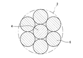
- FIG. 1 is a cross-sectional view showing an embodiment of an operation rope according to the present invention.
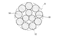
- FIG. 2 is a cross-sectional view showing another embodiment of the operating rope according to the present invention.
- FIG. 3 is a cross-sectional view showing still another embodiment of the operating rope according to the present invention.
- FIG. 4 is a perspective view for explaining the outline of the torque transmission performance evaluation test method for the operating rope.
- FIG. 5 is a graph in which the rotation angle on the proximal end side of the rope for operation is associated with the rotation angle on the distal end side at the same point.
- FIGS. 1 to 3 illustrate a plurality of embodiments of an operation wire rope (hereinafter also simply referred to as a rope) according to the present invention.
- Each of the ropes 2, 8, and 16 is composed of a strand obtained by twisting a plurality of strands.
- the present invention is not limited to the configuration according to the embodiment shown in FIGS.
- the rope 2 shown in FIG. 1 is constituted by a 1 + 6 layer twist composed of one core strand (core wire) 4 and six outermost strands (also called side strands) 6. ing.
- the rope 8 shown in FIG. 2 is constituted by a 3 + 9 layer twist composed of a core strand 12 composed of three strands 10 and nine side strands 14.
- the rope 16 shown in FIG. 3 is configured by a 1 + 6 + 12 layer twist composed of a core strand 18 which is a lower layer of a 1 + 6 layer twist and 12 side strands 20.
- side strands 20 having different diameters are used in order to make the cross-sectional shape close to a circle. However, it is not limited to this configuration, and all the strands 20 may have the same diameter.
- these ropes 2, 8, and 16 are suitable as a twist structure of the rope for operation used for a medical instrument, it is not limited to these.
- the ropes 2, 8, and 16 of these embodiments can be used for medical instruments.
- the rope attached to the medical instrument for operation has a base end connected to the hand operating part of the medical instrument and a distal end connected to the treatment part. Torque and push / pull force applied to the proximal end portion are transmitted to the distal end portion, and the treatment portion causes a treatment operation.
- the strands of the ropes 2, 8, and 16 are formed of austenitic stainless steel such as SUS304 or SUS316, nickel-titanium alloy, or the like. Of course, it is not limited to these materials.
- the tensile strength of the material of these strands is preferably 2000 MPa or more, more preferably 2500 MPa or more, and particularly preferably 2800 MPa or more.
- the mold rate of the side strands 6, 14, 20 or the side strands which are the outermost layers of the ropes 2, 8, 16 is set to be over 100% and 110% or less.
- This molding rate is the percentage obtained by dividing the spiral shape diameter (waviness diameter) of the side strand or side strand when the rope is loosened (unwinding) by the measured outer diameter of the rope. It is a thing.
- the molding rate within the above range, the rope becomes flexible and easily bent.
- the frictional force generated between the side strands or between the side strands is increased, and the frictional force between the side strands or side strands and the core wire or core strand is reduced. Energy loss when transmitting is reduced.
- the molding rate is 100% or less, the frictional force between the side strands or side strands and the core wire or core strand is increased, which may increase energy loss when transmitting the rotation of the rope. is there. Further, if the molding rate exceeds 110%, there is a possibility that a so-called open structure in which a gap is generated between the strands, and a desired rope diameter may not be obtained. From this viewpoint, it is preferable that the molding rate is 101% or more and 105% or less.
- the spiral of the side strands or side strands may be elliptical or oval rather than perfect circles. In other words, the spiral is flat.
- the major axis of the major axis and the minor axis is used as the waviness diameter for determining the above-described molding rate.
- the ropes 2, 8, and 16 are formed so that the molding rate is 110% or less even when the long diameter is used as the waviness diameter. Even if the minor axis is used as the undulation diameter, the ropes 2, 8, and 16 are formed so that the molding rate exceeds 100%.
- the flatness (also referred to as flatness) of the side strands 6, 14, 20 or the side strand which is the outermost layer of the ropes 2, 8, 16 is 1.01 or more and 1.10 or less.
- the flatness refers to the aspect ratio of the above-described flat spiral of the loosened side strands or side strands obtained by dividing the major axis by the minor axis.
- An example of a method for measuring the diameter of the spiral will be described below. On the projector, the loosened side strand or side strand is rotated about its central axis. In the process, the spiral diameter is measured at a plurality of arbitrary angular positions (for example, five locations).
- the plurality of angular positions are preferably equiangular intervals.
- the maximum value is determined as the major axis.
- the spiral diameter measured from the measurement direction of the major axis in the direction rotated by 90 ° around the central axis of the side strand or side strand is determined as the minor axis.
- a plurality of spirals are continuously formed along the axial direction of the loosened side strands or side strands. Therefore, the average value of a plurality of measured values (for example, arbitrary 10 locations) is adopted as each diameter in the direction intersecting 90 °.
- the flatness is less than 1.01, the frictional force between the side strands or strands and the core wires or strands becomes large, which may increase the energy loss when transmitting the rotation of the rope. .
- the flatness exceeds 1.10, a so-called open structure is obtained, and it may be difficult to stably manufacture the rope. From this viewpoint, the flatness is preferably 1.01 or more and 1.05 or less.
- the ropes 2, 8, and 16 have an initial elongation of 0.04% or more and 0.10% or less.
- the initial elongation rate of the rope is expressed as a percentage of the elongation rate (length increase rate) of the rope when a tensile load of 1.0% of the breaking load of the rope is applied. is there.
- the rope with a large initial elongation is flexible and easy to bend. That is, a rope with a large initial elongation has a low longitudinal elastic modulus (Young's modulus). If the initial elongation is less than 0.04%, the frictional force between the side strands or side strands and the core wire or core strand increases, which may increase energy loss when transmitting the rotation of the rope. There is. On the other hand, if the initial elongation exceeds 0.10%, the rope tends to have a so-called open structure, and it may be difficult to stably manufacture the rope.
- the initial elongation rate is confirmed by a tensile test of the target rope.
- This tensile test can be performed in accordance with the provisions of JISZ2241 (2011).
- the breaking load of the test rope is measured.
- the increment of the gauge distance set in the axial direction of the test rope is measured.
- the initial elongation is obtained by expressing this increment as a percentage of the original mark distance.
- the twist angle of the side strands 6, 14, 20 or the side strands of the ropes 2, 8, 16 is preferably 15 ° or more.
- a rope having a twist angle of 15 ° or more can easily achieve an initial elongation of 0.04% or more.
- a twist angle means the angle which a strand or a strand makes with the central axis of a rope or a strand.
- the side strand or the side strand refers to an angle formed with the central axis of the rope.
- each strand which comprises a rope is adjusted so that the required tensile strength may be obtained in a wire drawing process.
- preforming is performed on the side strands or side strands so that the required shaping rate and flatness can be obtained by the preformer. In particular, it is preformed so that the cross section of the spiral of the side strands or side strands is flat.
- continuous processing is performed instead of batch processing. Specifically, tension is applied to the rope to be processed passing through the heat treatment furnace at each of the entrances and exits of the heat treatment furnace. By doing so, the straightness of the rope is improved. Further, the molding rate and flatness of the side strands or side strands are determined.
- Example 1-12 Each operation wire rope of Example 1-12 having the configuration shown in FIG. 1 was obtained. These ropes are wire ropes for medical devices.
- the material of all the strands is SUS304 austenitic stainless steel.
- the outer diameter (cord diameter) of the rope is 0.7 mm
- the outer diameter of the core wire is 0.25 mm
- the outer diameter of the side strand is 0.23 mm.
- All the strands have a tensile strength of 2850 MPa. All of these ropes have a twisted structure of 1 + 6 and a twist pitch of 5.5 mm.
- the heat treatment temperatures of the ropes of Example 1-12 are all 500 ° C.
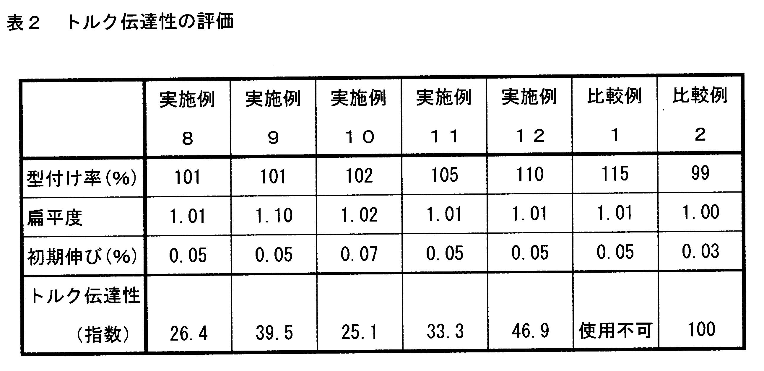
- Table 1 and Table 2 show the molding rate, flatness, and initial elongation of the side strands of the rope of Example 1-12.
- Table 2 shows the molding rate, flatness, and initial elongation, and the operation wire rope of Comparative Example 1 was obtained in the same manner as in Example 1 except that the cord diameter greatly exceeded 0.7 mm. It was. As shown in Table 2, since the molding rate of the rope of Comparative Example 1 was set to 115%, a so-called open structure was formed in which many voids were generated between the strands. For this reason, the cord diameter greatly exceeded 0.7 mm. The rope of Comparative Example 1 was not presented as an operation wire rope for medical devices, and was determined to be impossible to use as an operation wire rope for medical devices.
- Comparative Example 2 is an operation wire rope according to the related art.
- the operation wire rope of Comparative Example 2 is the same as Example 1 except that the molding rate, flatness, and initial elongation are as shown in Table 2.
- the side strands of the rope of Comparative Example 2 are not flattened.
- Torque transmission is evaluated by the difference between the rotation angle on the base end side (corresponding to the treatment section) and the rotation angle on the distal end side (corresponding to the treatment section) when the base end side (corresponding to the operation section) of each rope is rotated.
- a torque transmission evaluation test was carried out on the ropes of Examples and Comparative Examples as follows.
- a double spiral having a diameter of 200 mm is formed for each rope of Example 1-12 and Comparative Examples 1 and 2.
- This double spiral is formed by inserting, for example, the test rope 2 into the inside of a small diameter pipe 22 that is formed in a double spiral shape having a diameter of 200 mm and both ends are linear. Done.
- a rotational force around the central axis is applied to the base end side of the test rope 2. While the rotational force is applied, the rotation angle of the proximal end side 2A and the rotation angle of the distal end side 2B of the rope 2 are simultaneously measured.
- FIG. 5 is a graph in which the rotation angle on the proximal end side of the rope and the rotation angle on the distal end side at the same point are associated with each other.
- FIG. 5 is a graph showing the relationship between the input rotation angle and the output rotation angle with respect to the operation rope.
- the unit of angle is degree (°).
- a broken line extending at an angle of 45 ° with respect to the horizontal axis and the vertical axis starting from 0 ° indicates the proximal end in the entire measurement angle range (range of the input rotation angle from 0 ° to about 720 °). It is a straight line indicating that the difference between the rotation angle and the rotation angle on the tip side is zero.
- the difference between the rotation angle on the proximal end side and the rotation angle on the distal end side, which is the evaluation target of the test rope, is expressed as the difference in the vertical axis direction between the 45 ° inclined straight line and the measurement value curve in the figure.
- This difference in rotation angle corresponds to the rotation angle on the base end side.
- the difference in the rotation angle is shown larger than the actual difference for easy understanding.
- the maximum angle difference among the measured rotation angle differences is set as an evaluation target.
- the maximum angle difference between the ropes of Example 1-12 and Comparative Examples 1 and 2 is shown in Tables 1 and 2 by the index when the maximum angle difference of Comparative Example 2 is 100. The smaller the maximum angle difference, the smaller the exponent value and the better the torque transmission.
- the operating rope according to the present invention is suitable as an operating rope for a medical instrument.
Landscapes
- Health & Medical Sciences (AREA)
- Life Sciences & Earth Sciences (AREA)
- Surgery (AREA)
- Engineering & Computer Science (AREA)
- Animal Behavior & Ethology (AREA)
- General Health & Medical Sciences (AREA)
- Veterinary Medicine (AREA)
- Public Health (AREA)
- Biomedical Technology (AREA)
- Heart & Thoracic Surgery (AREA)
- Medical Informatics (AREA)
- Molecular Biology (AREA)
- Nuclear Medicine, Radiotherapy & Molecular Imaging (AREA)
- General Engineering & Computer Science (AREA)
- Physics & Mathematics (AREA)
- Biophysics (AREA)
- Optics & Photonics (AREA)
- Pathology (AREA)
- Radiology & Medical Imaging (AREA)
- Oral & Maxillofacial Surgery (AREA)
- Mechanical Engineering (AREA)
- Ropes Or Cables (AREA)
- Surgical Instruments (AREA)
- Endoscopes (AREA)
Abstract
Description
図1に示された構成を備えた実施例1-12の各操作用ワイヤロープを得た。これらのロープは、医療機器用のワイヤロープである。全ての素線の材質が、SUS304オーステナイト系ステンレス鋼である。ロープの外径(コード径)は0.7mm、芯線の外径は0.25mm、及び、側素線の外径は0.23mmである。いずれの素線も、その引っ張り強度は2850MPaである。これらのロープの撚り構成はいずれも1+6の層撚りであり、撚りピッチはいずれも5.5mmである。実施例1-12のロープの熱処理温度は、いずれも500°Cである。実施例1-12のロープの側素線の型付け率、扁平度及び初期伸びは、表1及び表2に示されるとおりである。
型付け率、扁平度及び初期伸びが表2に示されるとおりであり、コード径が0.7mmを大幅に超えている他は実施例1と同様にして、比較例1の操作用ワイヤロープを得た。表2に示されるとおり、比較例1のロープの型付け率を115%としたため、素線間に多くの空隙が生じる、いわゆるオープン構造となった。このため、コード径が0.7mmを大幅に超えた。かかる比較例1のロープは、医療機器用の操作用ワイヤロープとしての呈を成しておらず、医療機器用の操作用ワイヤロープとしての使用は不可能であると判断された。
比較例2は、従来技術に係る操作用ワイヤロープである。この比較例2の操作用ワイヤロープは、型付け率、扁平度及び初期伸びが表2に示されるとおりである他は、実施例1と同等である。この比較例2のロープの側素線については、扁平形状にはされていない。

トルク伝達性は、各ロープの基端側(操作部に相当)を回転させたときの、基端側の回転角と先端側(処置部に相当)の回転角との差によって評価される。実施例及び比較例の各ロープに対し、以下のごとくトルク伝達性の評価試験が実施された。
4・・・芯線
6、14、20・・・側素線
10・・・素線
12、18・・・コアストランド
Claims (6)
- 最外層である側素線又は側ストランドの型付け率が、100%を超え110%以下である操作用ロープ。
- 上記型付けされている側素線又は側ストランドが呈しているスパイラル形状の、長径を短径で除した縦横比である扁平度が、1.01以上1.10以下である請求項1に記載の操作用ロープ。
- 破断荷重の1.0%の引っ張り荷重が負荷されたときの伸び率が、0.04%以上0.10%以下である請求項1又は2に記載の操作用ロープ。
- 上記型付け率が、101%以上105%以下である請求項1から3のいずれかに記載の操作用ロープ。
- 上記扁平度が、1.01以上1.05以下である請求項2に記載の操作用ロープ。
- 上記型付けされている側素線又は側ストランドの撚り角が、15°以上である請求項1から5のいずれかに記載の操作用ロープ。
Priority Applications (4)
| Application Number | Priority Date | Filing Date | Title |
|---|---|---|---|
| CN201680036869.9A CN107735526B (zh) | 2015-06-26 | 2016-04-22 | 操作用绳 |
| EP16814033.3A EP3290580B1 (en) | 2015-06-26 | 2016-04-22 | Manipulation rope |
| US15/570,930 US10683609B2 (en) | 2015-06-26 | 2016-04-22 | Manipulation rope |
| KR1020177032352A KR101983933B1 (ko) | 2015-06-26 | 2016-04-22 | 조작용 로프 |
Applications Claiming Priority (2)
| Application Number | Priority Date | Filing Date | Title |
|---|---|---|---|
| JP2015-128519 | 2015-06-26 | ||
| JP2015128519A JP5870226B1 (ja) | 2015-06-26 | 2015-06-26 | 操作用ロープ |
Publications (1)
| Publication Number | Publication Date |
|---|---|
| WO2016208262A1 true WO2016208262A1 (ja) | 2016-12-29 |
Family
ID=55360953
Family Applications (1)
| Application Number | Title | Priority Date | Filing Date |
|---|---|---|---|
| PCT/JP2016/062746 Ceased WO2016208262A1 (ja) | 2015-06-26 | 2016-04-22 | 操作用ロープ |
Country Status (6)
| Country | Link |
|---|---|
| US (1) | US10683609B2 (ja) |
| EP (1) | EP3290580B1 (ja) |
| JP (1) | JP5870226B1 (ja) |
| KR (1) | KR101983933B1 (ja) |
| CN (1) | CN107735526B (ja) |
| WO (1) | WO2016208262A1 (ja) |
Families Citing this family (6)
| Publication number | Priority date | Publication date | Assignee | Title |
|---|---|---|---|---|
| JP5870227B1 (ja) * | 2015-06-26 | 2016-02-24 | トクセン工業株式会社 | 操作用ロープ |
| CN108431313B (zh) * | 2015-12-21 | 2021-04-27 | 日本板硝子株式会社 | 橡胶增强用帘线及使用其的橡胶制品 |
| JP6423374B2 (ja) * | 2016-01-07 | 2018-11-14 | トクセン工業株式会社 | 操作用中空撚り線 |
| JP6616811B2 (ja) * | 2017-09-05 | 2019-12-04 | トクセン工業株式会社 | 医療機器の操作用ロープ |
| CN108867122A (zh) * | 2018-07-26 | 2018-11-23 | 江苏鸿泽不锈钢丝绳有限公司 | (1+6+6/6)结构的汽车车窗升降用不锈钢钢丝绳 |
| KR102520595B1 (ko) * | 2021-04-26 | 2023-04-10 | 홍익대학교 산학협력단 | 냉간인발된 형상기억합금 와이어를 이용한 케이블 및 그 제조방법 |
Citations (8)
| Publication number | Priority date | Publication date | Assignee | Title |
|---|---|---|---|---|
| JPH0162396U (ja) * | 1987-10-16 | 1989-04-20 | ||
| JP2006283259A (ja) * | 2005-04-05 | 2006-10-19 | Chuo Spring Co Ltd | ワイヤロープおよびコントロールケーブル |
| JP2008017954A (ja) * | 2006-07-11 | 2008-01-31 | Hi-Lex Corporation | 骨切りワイヤおよびそれに用いるワイヤガイドチューブ |
| JP2008155052A (ja) * | 2008-03-24 | 2008-07-10 | Asahi Intecc Co Ltd | 医療用ガイドワイヤ |
| JP2011006803A (ja) * | 2009-06-24 | 2011-01-13 | Hi-Lex Corporation | 回転トルク伝達用のインナーケーブル、それを用いたコントロールケーブルおよびドア開閉機構 |
| JP2011202321A (ja) * | 2010-03-26 | 2011-10-13 | Sumitomo Denko Steel Wire Kk | 環状金属コード、無端金属ベルト及び環状金属コードの製造方法 |
| JP2012082530A (ja) * | 2010-10-06 | 2012-04-26 | Sumitomo Denko Steel Wire Kk | 環状金属コード、無端金属ベルト及び環状金属コードの製造方法 |
| JP2012157378A (ja) * | 2011-01-28 | 2012-08-23 | Olympus Corp | 処置具用ワイヤーおよび処置具 |
Family Cites Families (28)
| Publication number | Priority date | Publication date | Assignee | Title |
|---|---|---|---|---|
| JPS62170594A (ja) | 1986-01-17 | 1987-07-27 | 東京製綱株式会社 | ゴム補強用スチ−ルコ−ド |
| ES2129557T3 (es) | 1991-12-27 | 1999-06-16 | Nippon Cable System Inc | Cable para accionamiento. |
| JP2669754B2 (ja) | 1991-12-27 | 1997-10-29 | 日本ケーブル・システム株式会社 | 操作用ロープ |
| US5609014A (en) * | 1992-04-20 | 1997-03-11 | Tokyo Rope Manufacturing Co., Ltd. | Rubber reinforcing steel cord |
| CA2109904C (en) | 1992-12-18 | 2004-09-14 | Pol Bruyneel | Multi-strand steel cord |
| JPH08126648A (ja) | 1994-11-02 | 1996-05-21 | Olympus Optical Co Ltd | 内視鏡用処置具 |
| DE69517153T2 (de) | 1994-11-02 | 2001-02-01 | Olympus Optical Co., Ltd. | Mit endoskop funktionierendes instrument |
| JPH08176978A (ja) * | 1994-12-26 | 1996-07-09 | Bridgestone Corp | ゴム物品補強用スチールコード及び空気入りラジアルタイヤ |
| JP2942885B2 (ja) * | 1996-02-05 | 1999-08-30 | 東京製綱株式会社 | ゴム補強用スチールコードおよびラジアルタイヤ |
| JPH09256285A (ja) * | 1996-03-26 | 1997-09-30 | Sumitomo Electric Ind Ltd | 金属コード、その製造法及び装置、同コードを用いたゴム複合物 |
| US6109017A (en) * | 1996-05-16 | 2000-08-29 | Tokyo Rope Mfg. Co., Ltd. | Steel cord and steel radial tire |
| US6023026A (en) * | 1996-10-02 | 2000-02-08 | Nippon Cable Systems Inc. | Wire rope |
| DE60031806T2 (de) * | 1999-07-07 | 2007-09-20 | Sumitomo Rubber Industries Ltd., Kobe | Luftreifen |
| EP1120293B1 (en) * | 1999-12-22 | 2005-03-09 | Sumitomo Rubber Industries Ltd. | Pneumatic tyre |
| US6881194B2 (en) * | 2001-03-21 | 2005-04-19 | Asahi Intec Co., Ltd. | Wire-stranded medical hollow tube, and a medical guide wire |
| JP4098613B2 (ja) * | 2002-12-11 | 2008-06-11 | 朝日インテック株式会社 | 中空撚線コイル体と、それを用いて成る医療用器具、ならびに、その製造方法 |
| JP4488761B2 (ja) * | 2003-02-27 | 2010-06-23 | 中央発條株式会社 | ワイヤロープおよびコントロールケーブル |
| JP4084245B2 (ja) | 2003-06-24 | 2008-04-30 | 朝日インテック株式会社 | 操作用ワイヤロープを用いて成る医療用処置具 |
| JP3101207U (ja) | 2003-10-23 | 2004-06-10 | 東洋ミニロープ工業株式会社 | 操作用ワイヤーロープ |
| WO2006004054A1 (ja) * | 2004-07-05 | 2006-01-12 | Sumitomo(Sei) Steel Wire Corp. | 環状同芯撚りビードコード |
| JP4799208B2 (ja) * | 2005-03-11 | 2011-10-26 | 株式会社ハイレックスコーポレーション | 操作用インナーケーブル |
| JP2007177362A (ja) * | 2005-12-27 | 2007-07-12 | Tokusen Kogyo Co Ltd | ゴム製品補強用スチールコード |
| ES2379642T3 (es) * | 2006-08-31 | 2012-04-30 | Bridgestone Corporation | Cable de acero |
| JP2009241923A (ja) * | 2008-03-14 | 2009-10-22 | Sumitomo Denko Steel Wire Kk | 環状同芯撚りビードコード、その製造方法、及び車両用タイヤ |
| US8800257B2 (en) * | 2010-07-16 | 2014-08-12 | E I Du Pont De Nemours And Company | Composite cord and method of making and support structure and tire containing same |
| EP2773811B1 (en) * | 2011-11-02 | 2017-07-19 | Teijin Aramid B.V. | Polyethylene rope with low strength loss during use |
| CN104532633A (zh) * | 2014-12-24 | 2015-04-22 | 鞍钢钢绳有限责任公司 | 一种钢丝绳成形率的控制方法 |
| JP6611237B2 (ja) * | 2015-08-31 | 2019-11-27 | トクセン工業株式会社 | 操作用中空撚り線 |
-
2015
- 2015-06-26 JP JP2015128519A patent/JP5870226B1/ja active Active
-
2016
- 2016-04-22 EP EP16814033.3A patent/EP3290580B1/en active Active
- 2016-04-22 CN CN201680036869.9A patent/CN107735526B/zh active Active
- 2016-04-22 KR KR1020177032352A patent/KR101983933B1/ko active Active
- 2016-04-22 WO PCT/JP2016/062746 patent/WO2016208262A1/ja not_active Ceased
- 2016-04-22 US US15/570,930 patent/US10683609B2/en active Active
Patent Citations (8)
| Publication number | Priority date | Publication date | Assignee | Title |
|---|---|---|---|---|
| JPH0162396U (ja) * | 1987-10-16 | 1989-04-20 | ||
| JP2006283259A (ja) * | 2005-04-05 | 2006-10-19 | Chuo Spring Co Ltd | ワイヤロープおよびコントロールケーブル |
| JP2008017954A (ja) * | 2006-07-11 | 2008-01-31 | Hi-Lex Corporation | 骨切りワイヤおよびそれに用いるワイヤガイドチューブ |
| JP2008155052A (ja) * | 2008-03-24 | 2008-07-10 | Asahi Intecc Co Ltd | 医療用ガイドワイヤ |
| JP2011006803A (ja) * | 2009-06-24 | 2011-01-13 | Hi-Lex Corporation | 回転トルク伝達用のインナーケーブル、それを用いたコントロールケーブルおよびドア開閉機構 |
| JP2011202321A (ja) * | 2010-03-26 | 2011-10-13 | Sumitomo Denko Steel Wire Kk | 環状金属コード、無端金属ベルト及び環状金属コードの製造方法 |
| JP2012082530A (ja) * | 2010-10-06 | 2012-04-26 | Sumitomo Denko Steel Wire Kk | 環状金属コード、無端金属ベルト及び環状金属コードの製造方法 |
| JP2012157378A (ja) * | 2011-01-28 | 2012-08-23 | Olympus Corp | 処置具用ワイヤーおよび処置具 |
Non-Patent Citations (1)
| Title |
|---|
| See also references of EP3290580A4 * |
Also Published As
| Publication number | Publication date |
|---|---|
| KR20170134721A (ko) | 2017-12-06 |
| JP5870226B1 (ja) | 2016-02-24 |
| KR101983933B1 (ko) | 2019-05-29 |
| EP3290580A1 (en) | 2018-03-07 |
| JP2017008464A (ja) | 2017-01-12 |
| US10683609B2 (en) | 2020-06-16 |
| EP3290580A4 (en) | 2019-01-02 |
| CN107735526A (zh) | 2018-02-23 |
| CN107735526B (zh) | 2021-07-02 |
| US20180105981A1 (en) | 2018-04-19 |
| EP3290580B1 (en) | 2021-09-22 |
Similar Documents
| Publication | Publication Date | Title |
|---|---|---|
| JP6611237B2 (ja) | 操作用中空撚り線 | |
| JP5870226B1 (ja) | 操作用ロープ | |
| US8608670B2 (en) | Guidewire | |
| US8622932B2 (en) | Guidewire | |
| JP5870227B1 (ja) | 操作用ロープ | |
| US11554408B2 (en) | Hollow stranded wire | |
| JP6616811B2 (ja) | 医療機器の操作用ロープ | |
| JP5999708B2 (ja) | コイル体、およびコイル体を備えるガイドワイヤ、カテーテル、および医療用処置具 | |
| JP6423374B2 (ja) | 操作用中空撚り線 | |
| JPWO2017077626A1 (ja) | 医療用ワイヤおよび医療機器 | |
| CN103987992B (zh) | 具有平的或压扁的细丝的中国式指套 | |
| JP7721497B2 (ja) | 操作用ロープ | |
| JP7458469B1 (ja) | 医療処置具用のストレートワイヤ | |
| JP2022190735A (ja) | コイル体 | |
| JP2007260382A (ja) | カテーテルチューブ製造用芯材及びその製造方法並びにカテーテルチューブ及びその製造方法 | |
| TH2001005259A (th) | เส้นตีเกลียวเสริมยางเหล็กกล้า และ ล้อยาง | |
| JP2006230837A (ja) | 内視鏡の湾曲装置 |
Legal Events
| Date | Code | Title | Description |
|---|---|---|---|
| 121 | Ep: the epo has been informed by wipo that ep was designated in this application |
Ref document number: 16814033 Country of ref document: EP Kind code of ref document: A1 |
|
| WWE | Wipo information: entry into national phase |
Ref document number: 15570930 Country of ref document: US |
|
| ENP | Entry into the national phase |
Ref document number: 20177032352 Country of ref document: KR Kind code of ref document: A |
|
| WWE | Wipo information: entry into national phase |
Ref document number: 2016814033 Country of ref document: EP |
|
| NENP | Non-entry into the national phase |
Ref country code: DE |