WO2016208271A1 - 全固体二次電池およびその製造方法 - Google Patents
全固体二次電池およびその製造方法 Download PDFInfo
- Publication number
- WO2016208271A1 WO2016208271A1 PCT/JP2016/063132 JP2016063132W WO2016208271A1 WO 2016208271 A1 WO2016208271 A1 WO 2016208271A1 JP 2016063132 W JP2016063132 W JP 2016063132W WO 2016208271 A1 WO2016208271 A1 WO 2016208271A1
- Authority
- WO
- WIPO (PCT)
- Prior art keywords
- electrode layer
- solid
- positive electrode
- negative electrode
- layer
- Prior art date
- Legal status (The legal status is an assumption and is not a legal conclusion. Google has not performed a legal analysis and makes no representation as to the accuracy of the status listed.)
- Ceased
Links
Images


Classifications
-
- H—ELECTRICITY
- H01—ELECTRIC ELEMENTS
- H01M—PROCESSES OR MEANS, e.g. BATTERIES, FOR THE DIRECT CONVERSION OF CHEMICAL ENERGY INTO ELECTRICAL ENERGY
- H01M10/00—Secondary cells; Manufacture thereof
- H01M10/05—Accumulators with non-aqueous electrolyte
- H01M10/058—Construction or manufacture
- H01M10/0585—Construction or manufacture of accumulators having only flat construction elements, i.e. flat positive electrodes, flat negative electrodes and flat separators
-
- H—ELECTRICITY
- H01—ELECTRIC ELEMENTS
- H01M—PROCESSES OR MEANS, e.g. BATTERIES, FOR THE DIRECT CONVERSION OF CHEMICAL ENERGY INTO ELECTRICAL ENERGY
- H01M10/00—Secondary cells; Manufacture thereof
- H01M10/02—Details
-
- H—ELECTRICITY
- H01—ELECTRIC ELEMENTS
- H01M—PROCESSES OR MEANS, e.g. BATTERIES, FOR THE DIRECT CONVERSION OF CHEMICAL ENERGY INTO ELECTRICAL ENERGY
- H01M10/00—Secondary cells; Manufacture thereof
- H01M10/04—Construction or manufacture in general
- H01M10/0436—Small-sized flat cells or batteries for portable equipment
-
- H—ELECTRICITY
- H01—ELECTRIC ELEMENTS
- H01M—PROCESSES OR MEANS, e.g. BATTERIES, FOR THE DIRECT CONVERSION OF CHEMICAL ENERGY INTO ELECTRICAL ENERGY
- H01M10/00—Secondary cells; Manufacture thereof
- H01M10/04—Construction or manufacture in general
- H01M10/0486—Frames for plates or membranes
-
- H—ELECTRICITY
- H01—ELECTRIC ELEMENTS
- H01M—PROCESSES OR MEANS, e.g. BATTERIES, FOR THE DIRECT CONVERSION OF CHEMICAL ENERGY INTO ELECTRICAL ENERGY
- H01M10/00—Secondary cells; Manufacture thereof
- H01M10/05—Accumulators with non-aqueous electrolyte
- H01M10/056—Accumulators with non-aqueous electrolyte characterised by the materials used as electrolytes, e.g. mixed inorganic/organic electrolytes
- H01M10/0561—Accumulators with non-aqueous electrolyte characterised by the materials used as electrolytes, e.g. mixed inorganic/organic electrolytes the electrolyte being constituted of inorganic materials only
- H01M10/0562—Solid materials
-
- H—ELECTRICITY
- H01—ELECTRIC ELEMENTS
- H01M—PROCESSES OR MEANS, e.g. BATTERIES, FOR THE DIRECT CONVERSION OF CHEMICAL ENERGY INTO ELECTRICAL ENERGY
- H01M10/00—Secondary cells; Manufacture thereof
- H01M10/05—Accumulators with non-aqueous electrolyte
- H01M10/056—Accumulators with non-aqueous electrolyte characterised by the materials used as electrolytes, e.g. mixed inorganic/organic electrolytes
- H01M10/0564—Accumulators with non-aqueous electrolyte characterised by the materials used as electrolytes, e.g. mixed inorganic/organic electrolytes the electrolyte being constituted of organic materials only
- H01M10/0565—Polymeric materials, e.g. gel-type or solid-type
-
- H—ELECTRICITY
- H01—ELECTRIC ELEMENTS
- H01M—PROCESSES OR MEANS, e.g. BATTERIES, FOR THE DIRECT CONVERSION OF CHEMICAL ENERGY INTO ELECTRICAL ENERGY
- H01M4/00—Electrodes
- H01M4/02—Electrodes composed of, or comprising, active material
- H01M4/64—Carriers or collectors
-
- H—ELECTRICITY
- H01—ELECTRIC ELEMENTS
- H01M—PROCESSES OR MEANS, e.g. BATTERIES, FOR THE DIRECT CONVERSION OF CHEMICAL ENERGY INTO ELECTRICAL ENERGY
- H01M4/00—Electrodes
- H01M4/02—Electrodes composed of, or comprising, active material
- H01M2004/026—Electrodes composed of, or comprising, active material characterised by the polarity
- H01M2004/027—Negative electrodes
-
- H—ELECTRICITY
- H01—ELECTRIC ELEMENTS
- H01M—PROCESSES OR MEANS, e.g. BATTERIES, FOR THE DIRECT CONVERSION OF CHEMICAL ENERGY INTO ELECTRICAL ENERGY
- H01M4/00—Electrodes
- H01M4/02—Electrodes composed of, or comprising, active material
- H01M2004/026—Electrodes composed of, or comprising, active material characterised by the polarity
- H01M2004/028—Positive electrodes
-
- H—ELECTRICITY
- H01—ELECTRIC ELEMENTS
- H01M—PROCESSES OR MEANS, e.g. BATTERIES, FOR THE DIRECT CONVERSION OF CHEMICAL ENERGY INTO ELECTRICAL ENERGY
- H01M2300/00—Electrolytes
- H01M2300/0017—Non-aqueous electrolytes
- H01M2300/0065—Solid electrolytes
-
- Y—GENERAL TAGGING OF NEW TECHNOLOGICAL DEVELOPMENTS; GENERAL TAGGING OF CROSS-SECTIONAL TECHNOLOGIES SPANNING OVER SEVERAL SECTIONS OF THE IPC; TECHNICAL SUBJECTS COVERED BY FORMER USPC CROSS-REFERENCE ART COLLECTIONS [XRACs] AND DIGESTS
- Y02—TECHNOLOGIES OR APPLICATIONS FOR MITIGATION OR ADAPTATION AGAINST CLIMATE CHANGE
- Y02E—REDUCTION OF GREENHOUSE GAS [GHG] EMISSIONS, RELATED TO ENERGY GENERATION, TRANSMISSION OR DISTRIBUTION
- Y02E60/00—Enabling technologies; Technologies with a potential or indirect contribution to GHG emissions mitigation
- Y02E60/10—Energy storage using batteries
-
- Y—GENERAL TAGGING OF NEW TECHNOLOGICAL DEVELOPMENTS; GENERAL TAGGING OF CROSS-SECTIONAL TECHNOLOGIES SPANNING OVER SEVERAL SECTIONS OF THE IPC; TECHNICAL SUBJECTS COVERED BY FORMER USPC CROSS-REFERENCE ART COLLECTIONS [XRACs] AND DIGESTS
- Y02—TECHNOLOGIES OR APPLICATIONS FOR MITIGATION OR ADAPTATION AGAINST CLIMATE CHANGE
- Y02P—CLIMATE CHANGE MITIGATION TECHNOLOGIES IN THE PRODUCTION OR PROCESSING OF GOODS
- Y02P70/00—Climate change mitigation technologies in the production process for final industrial or consumer products
- Y02P70/50—Manufacturing or production processes characterised by the final manufactured product
Definitions
- the present invention relates to an all solid state secondary battery and a method for manufacturing the same.
- each constituent layer of the battery is formed by spraying a powder material on a base material together with a carrier gas while being charged, and depositing it by electrostatic force to form a film.
- a method of manufacturing a battery by forming and then pressing (pressurizing) a laminate composed of each of these constituent layers see, for example, Patent Document 1).
- the pressing force is uniformly applied to the whole at the time of pressure molding, that is, at the time of pressing, and the all solid secondary having good performance. A battery is obtained.
- the cause is the principal stress acting on the constituent layer made of powder (hereinafter referred to as the powder layer) due to the force applied during pressing and the shear stress generated by this principal stress. It turned out to be caused by That is, when a force is applied perpendicularly to the powder layer, a maximum principal stress is generated in the vertical direction, and a minimum principal stress is also generated in the lateral direction. The shear stress in an oblique direction is generated by these two main stresses. In other words, the shearing force works.
- the powder layer is laminated with a predetermined thickness, and its central part is pressed and hardened by pressing, but its peripheral part is inclined and thin. For this reason, the peripheral portion of the powder layer collapsed due to the shearing force, which led to an internal short circuit.
- an object of the present invention is to provide an all-solid-state secondary battery that can suppress an internal short circuit generated by pressing and a method for manufacturing the same.
- an all solid state secondary battery includes a laminate in which a positive electrode layer, a solid electrolyte layer, and a negative electrode layer are laminated between a pair of current collectors, and the laminate.
- An all-solid-state secondary battery in which a plate-like insulating member that is disposed around and electrically contacts at least the solid electrolyte layer and electrically insulates the positive electrode layer and the negative electrode layer is disposed, The inner edge portion of the insulating member that contacts the laminate is made thicker than the outer plate-like portion.
- the all-solid-state secondary battery according to the second invention is the all-solid-state secondary battery according to the first invention, wherein the insulating member is interposed between the pair of collectors through the positive electrode side adhesive layer and the negative electrode side adhesive layer.
- Each of the current collectors is provided with a strain absorption region by disposing the adhesive layers from the inner end portions of the insulating members.
- the method for producing an all-solid-state secondary battery according to the third invention includes a laminate in which a positive electrode layer, a solid electrolyte layer, and a negative electrode layer are laminated between a pair of current collectors, and the periphery of the laminate.
- a manufacturing method of an all-solid-state secondary battery in which a plate-shaped insulating member that is in contact with at least the solid electrolyte layer and electrically insulates the positive electrode layer and the negative electrode layer is disposed, Bonding a plate-like insulating member having an opening capable of guiding the positive electrode layer or the negative electrode layer on the surface of one current collector and having an inner edge of the opening thicker than the outside; Placing the positive electrode layer or the negative electrode layer in the opening of the insulating member bonded in this step; Disposing a solid electrolyte layer on the upper surface of the positive electrode layer or negative electrode layer disposed in this step; A step of disposing a negative electrode layer or a positive electrode layer on the upper surface of the solid electrolyte layer disposed in this step to obtain a laminate; And placing the other current collector on the upper surface of the laminate obtained in this step and then pressing the current collector.
- the contact inner edge with the laminated body made of an electrode layer or the like in the insulating member is made thicker than the outer plate-like part. It is possible to prevent the laminated body from collapsing due to the shearing force, and thus it is possible to prevent the occurrence of an internal short circuit.
- the all-solid-state secondary battery 1 includes a positive electrode layer 12, a solid electrolyte layer 32, and a negative electrode layer between a pair of current collectors, that is, a positive electrode current collector 11 and a negative electrode current collector 21.
- the contact inner edge portion 41b of the insulating member 41 with the laminate X is made thicker than the outer plate-like portion 41a.
- the insulating member 41 is bonded to the positive electrode current collector 11 and the negative electrode current collector 21 via a lower adhesive layer 51 and an upper adhesive layer 52.
- the lower adhesive layer 51 and the upper adhesive layer 52 are provided at predetermined distances (L1, L2) from the end face of the contact inner edge portion 41b of the insulating member 41, respectively. That is, the predetermined distance L1 of the positive electrode current collector 11 is an unconstrained portion that is not constrained by other members, and the predetermined distance L2 of the negative electrode current collector 21 is also an unconstrained portion that is not constrained by other members. . These unconstrained portions can be freely deformed. In other words, the unconstrained portions are portions that can absorb the strain generated when an external force is applied to the current collectors 11 and 21. That is, these unconstrained portions can be called strain absorbing regions.
- the insulating member 41 for example, an insulating sheet made of a polymer material such as a PET film is used.
- a pressure sensitive adhesive such as a double-sided adhesive tape is used.
- the insulating member 41 arranged around the laminate X is provided with an opening 41c for the laminate X to be laminated (also referred to as guided).
- the contact inner edge 41b that contacts X is a peripheral portion of the opening 41c.
- the thickness of the contact inner edge part 41b is made thicker (higher) than the total thickness of the positive electrode layer 12 and the solid electrolyte layer 32, for example.
- the positive electrode layer 12 and the negative electrode layer 22 a powdered electrode mixture is used, and the solid electrolyte layer 32 is also a powder. And about an electrode compound material, although the mixture of an electrode active material and a solid electrolyte is used, depending on the case, there may be only an electrode active material. Therefore, when it emphasizes that the said laminated body X is a powder, it is called a powder layer.
- the shape in plan view is a square (may be a circle or a polygon), and the length of one side is in the range of 30 to 300 mm. Further, it is appropriate that the thickness is in the range of 50 to 500 ⁇ m. Therefore, the planar view shape of the multilayer body X is square, and the planar view shape of the opening 41c for guiding the positive electrode layer 12 and the solid electrolyte layer 32 of the multilayer body X is also square.
- the all-solid-state secondary battery is placed on a horizontal plane, and the positive electrode side is shown below and the negative electrode side is arranged upward.
- the negative electrode side is down and the positive electrode side is down. It may be arranged above.
- the surface of the positive electrode current collector 11 has an opening 41c that can guide the positive electrode layer 12, and the contact inner edge 41b of the opening 41c is thicker than the outer plate-like portion 41a.
- the insulating member 41 is bonded via the lower adhesive layer 51.
- a strip-shaped sub-insulating member 41B having a predetermined width is bonded to the upper surface of the inner peripheral portion of the plate-shaped main insulating member 41A through an adhesive layer 53. explain.
- the positive electrode layer 12 is disposed on the surface of the positive electrode current collector 11 inside the opening 41c provided in the insulating member 41, that is, the main insulating member 41A.
- a solid electrolyte layer 32 is disposed on the upper surface of the positive electrode layer 12 with a predetermined thickness.
- the outer peripheral part of the solid electrolyte layer 32 is arrange
- the negative electrode layer 22 is arranged with a predetermined thickness on the upper surface of the solid electrolyte layer 32 to obtain a laminate X.
- the negative electrode current collector 21 having the upper adhesive layer 52 attached to the periphery is disposed on the upper surface of the negative electrode layer 22 and at a low pressure of about 5000 Pa while sucking air.
- the negative electrode current collector 21 is adhered to the upper surface of the insulating member 41 by the upper adhesive layer 52 by temporary pressing (temporary pressing).
- the main pressing (main pressing) is performed with a high pressure of about 10 ton / cm 2 in a state where the air inside is sucked.
- an elastic member such as a rubber plate is disposed between the negative electrode current collector 21 and a pressing member (not shown).
- Laminate packs are made by heat-sealing the surroundings.
- an all-solid-state secondary battery is configured by stacking a plurality of single batteries in series or in parallel.
- wrinkles of the current collectors 11 and 21 at the periphery of the powder layer generated by the pressing force applied to the laminated body X, that is, the powder layer are the strain absorption regions L1 and L2. Since it is diffused, it is possible to suppress the occurrence of deformation such as wrinkles in the powder layer portion, and therefore it is possible to prevent the occurrence of an internal short circuit due to the destruction of the layer structure at the periphery of the powder layer.
- this manufacturing method includes a laminate in which a positive electrode layer, a solid electrolyte layer, and a negative electrode layer are laminated between a pair of current collectors, and is disposed around the laminate and is in contact with at least the solid electrolyte layer.
- the portion of the insulating member that is in contact with the laminated body is thicker than the outer plate-like portion, and the portion of the insulating member that is in contact with the laminated body is the outer plate-like portion. It may be said that a collapse preventing portion that can prevent the peripheral portion of the laminated body from collapsing is provided, and the inner edge of the insulating member in contact with the laminated body is formed from the outer plate-like portion. It is also possible to say that a shear collapse prevention portion is provided that can prevent the peripheral edge of the laminate from shearing collapse when the battery is pressed.
- the positive electrode current collector 11 and the negative electrode current collector 21 copper (Cu), magnesium (Mg), stainless steel, titanium (Ti), iron (Fe), cobalt (Co), nickel (Ni), zinc (Zn) ), Aluminum (Al), germanium (Ge), indium (In), lithium (Li), tin (Sn), or an alloy thereof is used.
- the thin plate or foil has a thickness in the range of 5 ⁇ m to 100 ⁇ m.
- an aluminum foil is used as the positive electrode current collector 11 and a copper foil is used as the negative electrode current collector 21.
- the current collectors 11 and 21 have a surface subjected to a roughening treatment from the viewpoint of improving adhesion to the powder laminate X.
- the roughening process is a process for increasing the surface roughness by etching or the like.
- the positive electrode current collector 11 is made of an etched aluminum foil (also referred to as an etched aluminum foil).
- an etched copper foil also referred to as a roughened copper foil
- an insulating sheet made of a polymer material such as a PET film is used for the insulating member 41 (41A, 41B).
- the current collector that has been subjected to the etching process in this manner, the hole formed by the etching is crushed by the pressure at the time of manufacturing the all-solid-state secondary battery, and the electrode layer, that is, the positive electrode layer 12 and the negative electrode layer 22. It becomes easy to bite on the surface. Therefore, the current collector and these electrode layers are easily integrated.
- the electrode layer is a layer made of a mixed material in which an electrode active material that secures an electron conduction path between particles and a solid electrolyte having ion conductivity are mixed at a predetermined ratio in order to exchange electrons.
- an electrode active material that secures an electron conduction path between particles and a solid electrolyte having ion conductivity are mixed at a predetermined ratio in order to exchange electrons.
- the positive electrode active material suitable for the positive electrode layer 12 is not particularly limited as long as it can insert and release lithium ions.
- the positive electrode active material lithium-nickel composite oxide (LiNi x M 1-x O 2 , where M is Co, Al, Mn, V, Cr, Mg, Ca, Ti, Zr, Nb, Mo, and W
- a layered oxide such as lithium cobaltate (LiCoO 2 ), lithium nickelate (LiNiO 2 ), lithium manganate (LiMn 2 O 4 ), or lithium iron phosphate (LiFePO 4 ) having an olivine structure.
- Solid solutions such as lithium manganate having a spinel structure (LiMn 2 O 4 , Li 2 MnO 3 , LiMO 2 ) and mixtures thereof, and sulfides such as sulfur (S) and lithium sulfide (Li 2 S) It can also be used.
- a lithium / nickel / cobalt / aluminum composite oxide LiNi 0.8 Co 0.15 Al 0.05 O 2 , hereinafter referred to as an NCA-based composite oxide
- NCA-based composite oxide is used as the positive electrode active material.
- the negative electrode active material suitable for the negative electrode layer 22 carbon materials such as natural graphite, artificial graphite, graphite carbon fiber, and resin-fired carbon, and alloy materials that are combined with a solid electrolyte are used.
- alloy materials include lithium alloys (LiAl, LiZn, Li 3 Bi, Li 3 Cd, Li 3 Sb, Li 4 Si, Li 4.4 Pb, Li 4.4 Sn, Li 0.17 C, LiC. 6 ), and metal oxides such as lithium titanate (Li 4 Ti 5 O 12 ) and Zn.
- natural or artificial graphite is used as the negative electrode active material.
- zirconia zirconia
- alumina Al 2 O 3
- lithium titanate Li 4 Ti 5 O 12
- lithium niobate Li 4 NbO 3
- carbon What coated each (C) etc. can be used as an electrode active material.
- Solid electrolytes are roughly classified into organic polymer electrolytes (also referred to as organic solid electrolytes), inorganic inorganic solid electrolytes, and the like, and any of them may be used as the solid electrolyte.
- organic solid electrolytes are roughly classified into oxide-based materials and sulfide-based materials, and any of them may be used.
- the inorganic solid electrolyte can be appropriately selected from crystalline or amorphous ones. That is, the solid electrolyte can be appropriately selected from materials composed of organic compounds, inorganic compounds, or mixtures thereof.
- examples of materials that can be used as the solid electrolyte include lithium-containing metal oxides (such as one or more metals) such as Li 2 —SiO 2 and Li 2 —SiO 2 —P 2 O 5 , and Li x.
- lithium-containing metal oxides such as one or more metals
- Li 2 —SiO 2 and Li 2 —SiO 2 —P 2 O 5 lithium-containing metal oxides
- Li x lithium-containing metal oxides
- Lithium-containing metal nitrides such as P y O 1-z N 2 , Li 2 S—P 2 S 5 system, Li 2 S—SiS 2 system, Li 2 S—B 2 S 3 system, Li 2 S—GeS 2 system, Li 2 S-SiS 2 -LiI system, Li 2 S-SiS 2 -Li 3 PO 4 based, Li 2 S-Ge 2 S 2 system, Li 2 S-GeS 2 -P 2 S 5 based, Li 2 S-GeS 2 -ZnS-based lithium-containing sulfide-based glass such as, and PEO (polyethylene oxide), PVDF (polyvinylidene fluoride), lithium phosphate (Li 3 PO 4), lithium such as lithium titanium oxide Yes transition metal oxides.
- PEO polyethylene oxide
- PVDF polyvinylidene fluoride
- Li phosphate Li 3 PO 4
- lithium lithium titanium oxide Yes transition metal oxides.
- Li 2 SP—P 2 S 5 glass is used as the solid electrolyte, among sulfide inorganic solid electrolytes based on sulfide glass having high ion conductivity.
- the solid electrolyte suitable for the solid electrolyte layer 32 may be the same as or different from the solid electrolyte used in the positive electrode layer 12 and the negative electrode layer 22.
- a pressure sensitive adhesive such as a double-sided adhesive tape is used as the adhesive layer for ease of handling, but an adhesive such as liquid or solid may be used.
- the contact inner edge portion 41b of the insulating member 41 with the laminate X is made thicker than the outer plate-like portion 41a. Collapse due to the generated shearing force can be prevented, and therefore an internal short circuit (electrical short circuit) can be prevented from occurring. That is, the inner edge portion of the opening 41a in the insulating member 41 functions as a collapse prevention block that can prevent the shear collapse that occurs when the laminate X is pressed.
- the central portion becomes the thickest and the peripheral portion becomes thin.
- the force does not act much on the peripheral part, so that the adhesion between the powders becomes insufficient at this peripheral part, and the layer structure is formed by impact or deformation of the current collector. Although it becomes easy to be destroyed, such a situation can be avoided.
- a 20 ⁇ m thick roughened aluminum foil (etched aluminum) is used as the positive electrode current collector 11, and a 18 ⁇ m thick copper foil is used as the negative electrode current collector 21.
- a PET film polyethylene terephthalate film
- a pressure-sensitive adhesive film double-sided adhesive tape
- the adhesive layer 53 of the contact inner edge portion 41b is the same and has a width. 1 mm was used.
- an NCA-based composite oxide that is a positive electrode active material, and a glass ceramic made of Li 2 S (80 mol%)-P 2 S 5 (20 mol%) as a solid electrolyte are in a ratio of 7: 3. What was mixed with was used.
- graphite powder as a negative electrode active material and glass ceramic made of Li 2 S (80 mol%)-P 2 S 5 (20 mol%) as a solid electrolyte were mixed in a ratio of 6: 4. Things were used.
- As the solid electrolyte in the solid electrolyte layer 32 a glass ceramic made of Li 2 S (80 mol%)-P 2 S 5 (20 mol%) was used.
- the positive electrode layer 12 has a thickness of about 70 ⁇ m
- the negative electrode layer 22 has a thickness of about 130 ⁇ m
- the solid electrolyte layer 32 has a thickness of about 90 ⁇ m after this pressing.
- the all-solid-state secondary battery 1 was manufactured by heat-sealing the periphery to form a laminate pack.
- the contact inner edge portion of the opening of the insulating member disposed around the laminated body has been described as being thickened.
- the negative electrode collector shown in FIG. 10 An annular outer insulating member 42 that can be disposed along the outer side of the belt-like sub-insulating member 41B is adhered to the electric body 21 side via the upper adhesive layer 52, and when pressed (indicated by an arrow a), The outer insulating member 42 may be bonded to the upper surface of the plate-like portion 41A (41a) of the insulating member 41 via the adhesive layer 54. In other words, the entire thickness of the insulating member 41 is increased so as to be positioned above the lower surface of the solid electrolyte layer 32 of the stacked body X after pressing.
Landscapes
- Chemical & Material Sciences (AREA)
- Chemical Kinetics & Catalysis (AREA)
- Electrochemistry (AREA)
- General Chemical & Material Sciences (AREA)
- Engineering & Computer Science (AREA)
- Manufacturing & Machinery (AREA)
- Physics & Mathematics (AREA)
- Condensed Matter Physics & Semiconductors (AREA)
- General Physics & Mathematics (AREA)
- Inorganic Chemistry (AREA)
- Dispersion Chemistry (AREA)
- Secondary Cells (AREA)
Abstract
本発明は、製造過程の押圧時に周縁部に生じるせん断力による積層体の崩壊を防止することができ、したがって内部短絡が発生するのを防止することができる全固体二次電池およびその製造方法を提供する。本発明は、正極集電体(11)と負極集電体(21)との間に、正極層(12)、固体電解質層(32)および負極層(22)が積層されてなる積層体(X)、並びにこの積層体(X)の周囲に配置されるとともに少なくとも固体電解質層(32)と接触して正極層(12)と負極層(22)とを電気的に絶縁する板状の絶縁部材(41)が配置された全固体二次電池(1)であって、絶縁部材(41)における積層体(X)との接触内縁部(41b)を外側の板状部(41a)よりも厚くしたものである。
Description
本発明は、全固体二次電池およびその製造方法に関する。
通常、全固体二次電池は、正極層と負極層との間に固体電解質層が配置されるとともに、これら各電極層の外面にそれぞれ集電体が配置されたものである。ところで、このような全固体二次電池の製造方法としては、粉体材料を帯電させつつ搬送用ガスとともに基材に吹き付け、静電気力により付着させて成膜することにより、電池の各構成層を形成し、その後、これら各構成層よりなる積層体を押圧(加圧)することにより電池を製造する方法がある(例えば、特許文献1参照)。
この方法によれば、均一な厚さの粉体からなる構成層が形成されるので、加圧成型時すなわち押圧時にその押圧力が全体に均一に掛かることになり、性能が良い全固体二次電池が得られる。
しかし、上述したような製造方法で得られた全固体二次電池においても、内部短絡が発生していた。
この内部短絡の原因を検討した結果、その原因は、押圧時に加えられた力による粉体からなる構成層(以下、粉体層と称す)に作用する主応力およびこの主応力にて生じるせん断応力に起因するものと判明した。すなわち、粉体層に垂直に力が掛かると垂直方向に最大主応力が発生するとともに、横方向にも最小主応力が発生し、これら両主応力により斜め方向のせん断応力が発生する。言い換えれば、せん断力が働くことになる。
ところで、粉体層は所定厚さで積層されており、その中央部は押圧より押し固められるが、その周縁部は傾斜面となり薄くなっている。このため、せん断力により、粉体層の周縁部が崩壊し、内部短絡に繋がっていた。
そこで、本発明は、押圧により発生する内部短絡を抑制し得る全固体二次電池およびその製造方法を提供することを目的とする。
上記課題を解決するため、第1の発明に係る全固体二次電池は、一対の集電体の間に、正極層、固体電解質層および負極層が積層されてなる積層体、並びにこの積層体の周囲に配置されるとともに少なくとも固体電解質層と接触して正極層と負極層とを電気的に絶縁する板状の絶縁部材が配置された全固体二次電池であって、
上記絶縁部材における積層体との接触内縁部を外側の板状部よりも厚くしたものである。
上記絶縁部材における積層体との接触内縁部を外側の板状部よりも厚くしたものである。
また、第2の発明に係る全固体二次電池は、第1の発明の全固体二次電池において、一対の集電体の間に正極側接着層および負極側接着層を介して絶縁部材を配置するとともに、各接着層を絶縁部材の内方側端部からそれぞれ離すことにより、各集電体に歪吸収領域を具備させたものである。
さらに、第3の発明に係る全固体二次電池の製造方法は、一対の集電体の間に、正極層、固体電解質層および負極層が積層されてなる積層体、並びにこの積層体の周囲に配置されるとともに少なくとも固体電解質層と接触して正極層と負極層とを電気的に絶縁する板状の絶縁部材が配置された全固体二次電池の製造方法であって、
一方の集電体の表面に、正極層または負極層を案内し得る開口部を有し且つ当該開口部の内縁部が外側よりも厚くされた板状の絶縁部材を接着する工程と、
この工程で接着された絶縁部材の開口部内に正極層または負極層を配置する工程と、
この工程で配置された正極層または負極層の上面に固体電解質層を配置する工程と、
この工程で配置された固体電解質層の上面に負極層または正極層を配置して積層体を得る工程と、
この工程で得られた積層体の上面に、他方の集電体を配置した後、押圧する工程とを具備した方法である。
一方の集電体の表面に、正極層または負極層を案内し得る開口部を有し且つ当該開口部の内縁部が外側よりも厚くされた板状の絶縁部材を接着する工程と、
この工程で接着された絶縁部材の開口部内に正極層または負極層を配置する工程と、
この工程で配置された正極層または負極層の上面に固体電解質層を配置する工程と、
この工程で配置された固体電解質層の上面に負極層または正極層を配置して積層体を得る工程と、
この工程で得られた積層体の上面に、他方の集電体を配置した後、押圧する工程とを具備した方法である。
本発明の全固体二次電池およびその製造方法によれば、絶縁部材における電極層などからなる積層体との接触内縁部を、外側の板状部よりも厚くしたので、押圧時に周縁部に生じるせん断力による積層体の崩壊を防止することができ、したがって内部短絡が発生するのを防止することができる。
以下、本発明の実施の形態に係る全固体二次電池およびその製造方法について、図面に基づき説明する。
まず、全固体二次電池の構成について説明する。
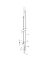
図1に示すように、この全固体二次電池1は、一対の集電体、すなわち正極集電体11と負極集電体21との間に、正極層12、固体電解質層32および負極層22が順番に積層されてなる積層体X、並びにこの積層体Xの周囲に配置されるとともに少なくとも固体電解質層32と接触して正極層12と負極層22とを電気的に絶縁する板状の絶縁部材41が配置された全固体二次電池であって、上記絶縁部材41における積層体Xとの接触内縁部41bを外側の板状部41aよりも厚くされたものである。また、絶縁部材41と正極集電体11および負極集電体21とは、下部接着層51および上部接着層52を介して接着されている。
ところで、この下部接着層51および上部接着層52については、上記絶縁部材41の接触内縁部41bの端面からそれぞれ所定距離(L1,L2)はなして設けられている。すなわち、正極集電体11の所定距離L1については、他の部材に拘束されない非拘束部分であり、また負極集電体21の所定距離L2についても、他の部材に拘束されない非拘束部分である。これら非拘束部分は、変形が自由であり、言い換えれば、各集電体11,21に外力が作用した際に発生する歪を吸収し得る部分である。すなわち、これら非拘束部分は、歪吸収領域と呼ぶことができる。
なお、上記絶縁部材41としては、例えばPETフィルムなどの高分子材料でできた絶縁シートが用いられる。また、上記各接着層51,52としては、両面接着テープなどの感圧接着材が用いられる。
さらに、上記積層体Xの周囲に配置される絶縁部材41には、この積層体Xが積層される(案内される、と言うこともできる)ための開口部41cが形成されており、積層体Xに接触する接触内縁部41bは、当該開口部41cの周縁部分である。また、接触内縁部41bの厚さは、例えば正極層12と固体電解質層32との合計厚さより厚く(高く)されている。
なお、正極層12および負極層22としては、粉末の電極合材が用いられるとともに、固体電解質層32についても、粉末のものが用いられる。そして、電極合材については、電極活物質と固体電解質との混合物が用いられるが、場合によっては、電極活物質だけの場合もある。したがって、上記積層体Xを、粉体であることを強調する場合に、粉体層と称する。
ここで、全固体二次電池1の形状および大きさについて説明すると、平面視形状が正方形(円形または多角形であってもよい)にされるとともに、その一辺の長さは30~300mmの範囲で、また、厚さは50~500μmの範囲とするのが適正である。したがって、積層体Xの平面視形状が正方形にされるとともに、積層体Xの正極層12および固体電解質層32を案内するための開口部41cの平面視形状も正方形にされている。
図1においては、全固体二次電池を水平面に載置した状態で且つ正極側を下方に、負極側を上方に配置したものとして示しているが、勿論、負極側を下方に、正極側を上方に配置したものでもよい。
なお、全固体二次電池の主要部分の構成材料については、製造方法を説明した後に、纏めて説明する。
以下、全固体二次電池の製造方法について、図2~図8に基づき、詳しく説明する。
図2に示すように、正極集電体11の表面に、正極層12を案内し得る開口部41cを有するとともにその開口部41cの接触内縁部41bがその外側の板状部41aよりも厚くされた絶縁部材41を、下部接着層51を介して接着する。
なお、ここでは、厚くされた接触内縁部41bとして、板状の主絶縁部材41Aの内周部分の上面に、所定幅の帯状の副絶縁部材41Bが接着層53を介して接着されたものとして説明する。
次に、図3に示すように、この絶縁部材41、すなわち主絶縁部材41Aに設けられた開口部41cの内方の正極集電体11の表面に正極層12を配置する。
次に、図4に示すように、この正極層12の上面に固体電解質層32を所定厚さでもって配置する。この場合、固体電解質層32の外周部は、例えば1mm幅の帯状の副絶縁部材41Bの上方を覆うように配置される。
次に、図5に示すように、固体電解質層32の上面に負極層22を所定厚さでもって配置して、積層体Xを得る。
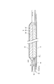
次に、図6および図7に示すように、負極層22の上面に、周囲に上部接着層52が取り付けられた負極集電体21を配置するとともに空気を吸引しながら5000Pa程度の低圧力でもって仮押圧(仮プレス)して、上部接着層52により、負極集電体21を絶縁部材41の上面に接着する。
次に、図8に示すように、内部の空気を吸引した状態で、10ton/cm2程度の高圧力でもって本押圧(本プレス)を行う。
なお、負極集電体21を上方から押圧する際には、負極集電体21と押圧部材(図示せず)との間には、弾性部材、例えばゴム板などが配置される。
そして、最後に、両集電体11,21間に積層体Xが配置されてなる電池を一対のステンレス板で挟んだ後、電気取り出し用タブリードが備えられたラミネートフィルムで挟み、真空下で、周囲を熱融着することによりラミネートパックを行う。
これにより、単体の全固体二次電池が得られる。通常、全固体二次電池は、単体の電池が、複数個、直列に積層されるか、または並列に配置されることにより構成される。
ところで、本押圧した際に、積層体Xに、すなわち粉体層に押圧力が加えられたことにより発生する粉体層周縁部における集電体11,21のしわが歪吸収領域L1,L2で拡散されるので、粉体層部分でしわなどの変形が発生するのを抑制でき、したがって粉体層周縁部での層構造の破壊に起因する内部短絡が発生するのを防止することができる。
上記製造方法の主要部分を、工程形式で記載すると、以下のようになる。
すなわち、この製造方法は、一対の集電体の間に、正極層、固体電解質層および負極層が積層されてなる積層体、並びにこの積層体の周囲に配置されるとともに少なくとも固体電解質層と接触して正極層と負極層とを電気的に絶縁する板状の絶縁部材が配置された全固体二次電池の製造方法であって、
一方の集電体の表面に、正極層または負極層を案内し得る開口部を有し且つ当該開口部の内縁部が外側よりも厚くされた板状の絶縁部材を接着する工程と、この工程で接着された絶縁部材の開口部内に正極層または負極層を配置する工程と、この工程で配置された正極層または負極層の上面に固体電解質層を配置する工程と、この工程で配置された固体電解質層の上面に負極層または正極層を配置して積層体を得る工程と、この工程で得られた積層体の上面に、他方の集電体を配置した後、押圧する工程とを備えた方法である。
一方の集電体の表面に、正極層または負極層を案内し得る開口部を有し且つ当該開口部の内縁部が外側よりも厚くされた板状の絶縁部材を接着する工程と、この工程で接着された絶縁部材の開口部内に正極層または負極層を配置する工程と、この工程で配置された正極層または負極層の上面に固体電解質層を配置する工程と、この工程で配置された固体電解質層の上面に負極層または正極層を配置して積層体を得る工程と、この工程で得られた積層体の上面に、他方の集電体を配置した後、押圧する工程とを備えた方法である。
なお、上述した実施の形態において、絶縁部材における積層体との接触内縁部を外側の板状部よりも厚くしたと言う部分を、絶縁部材における積層体との接触内縁部を外側の板状部よりも厚くして、積層体の周縁部が崩壊するのを防止し得る崩壊防止部を設けたと言うようにしてもよく、また絶縁部材における積層体との接触内縁部を外側の板状部よりも厚くして、当該電池の押圧時に積層体の周縁部がせん断崩壊するのを防止し得るせん断崩壊防止部を設けたと言うようにしてもよい。
ここで、上記全固体二次電池1の主要構成部材の材料について説明する。
正極集電体11および負極集電体21としては、銅(Cu)、マグネシウム(Mg)、ステンレス鋼、チタン(Ti)、鉄(Fe)、コバルト(Co)、ニッケル(Ni)、亜鉛(Zn)、アルミニウム(Al)、ゲルマニウム(Ge)、インジウム(In)、リチウム(Li)、錫(Sn)若しくはこれらの合金から成る薄板状体または箔状体が用いられる。ここで、薄板状体または箔状体は、その厚さが5μm~100μmの範囲内のものである。本実施の形態においては、正極集電体11としてはアルミニウム箔、負極集電体21としては銅箔が用いられる。さらに、各集電体11,21は、粉末の積層体Xとの密着性向上の観点から、その表面に粗化処理が施されたものであることが好ましい。粗化処理とは、エッチングなどで表面粗さを大きくする処理である。本実施の形態においては、正極集電体11には、エッチング処理されたアルミニウム箔(エッチドアルミ箔とも言う)が用いられる。また、負極集電体21には、エッチング処理された銅箔(粗化銅箔とも言う)が用いられるが、エッチング処理がされない銅箔を用いてもよい。さらに、絶縁部材41(41A,41B)には、PETフィルムなどの高分子材料でできた絶縁シートが用いられる。
このようにエッチング処理が施された集電体を用いることによって、全固体二次電池を製造する際の押圧で、エッチングによりできた孔部が潰され、電極層すなわち正極層12および負極層22の表面に喰い付きやすくなる。したがって、集電体とこれら電極層とが一体化されやすくなる。
また、電極層は、電子の授受を行うために粒子間に電子伝導パスを確保する電極活物質とイオン伝導性を有する固体電解質とを所定の割合で混合した混合材から成る層である。このように電極活物質にリチウムイオン伝導性を有する固体電解質を混合することにより、電子伝導性に加えてイオン伝導性が付与されるため、粒子間にイオン伝導パスを確保することができる。
正極層12に適した正極活物質としては、リチウムイオンの挿入離脱が可能なものであればよく、特に限定されない。例えば、正極活物質としては、リチウム・ニッケル複合酸化物(LiNixM1-xO2、ただしMはCo、Al、Mn、V、Cr、Mg、Ca、Ti、Zr、Nb、MoおよびWのうち少なくとも1つの元素)、コバルト酸リチウム(LiCoO2)、ニッケル酸リチウム(LiNiO2)、マンガン酸リチウム(LiMn2O4)などの層状酸化物、オリビン構造を持つリン酸鉄リチウム(LiFePO4)、スピネル構造を持つマンガン酸リチウム(LiMn2O4、Li2MnO3、LiMO2)などの固溶体やそれらの混合物、さらに硫黄(S)、硫化リチウム(Li2S)などの硫化物などを用いることもできる。本実施の形態においては、正極活物質として、リチウム・ニッケル・コバルト・アルミニウム複合酸化物(LiNi0.8Co0.15Al0.05O2、以下NCA系複合酸化物と称する)が用いられる。
一方、負極層22に適した負極活物質としては、天然黒鉛、人造黒鉛、黒鉛炭素繊維、樹脂焼成炭素などの炭素材料や、固体電解質と合材化される合金系材料が用いられる。合金系材料としては、例えば、リチウム合金(LiAl,LiZn,Li3Bi,Li3Cd,Li3Sb,Li4Si,Li4.4Pb,Li4.4Sn,Li0.17C,LiC6など)や、チタン酸リチウム(Li4Ti5O12)、Znなどの金属酸化物などが挙げられる。本実施の形態においては、負極活物質として、天然・人造などの黒鉛が用いられる。
また、正極活物質および負極活物質の表面に、ジルコニア(ZrO2)、アルミナ(Al2O3)、チタン酸リチウム(Li4Ti5O12)、ニオブ酸リチウム(Li4NbO3)、炭素(C)などをそれぞれコーティングしたものを電極活物質として使用することができる。
固体電解質は、有機系のポリマー電解質(有機固体電解質とも言う)、無機系の無機固体電解質などに大別されるが、固体電解質として、いずれを用いても構わない。また、無機固体電解質は、酸化物系の材料および硫化物系の材料に大別されるが、いずれを用いても構わない。さらに、無機固体電解質においては、結晶性または非晶質のもののうちから適宜選択することができる。すなわち、固体電解質は、有機化合物、無機化合物またはこれらの混合物から成る材料から適宜選択することができる。具体的には、固体電解質として用いることのできる材料としては、例えば、Li2-SiO2、Li2-SiO2-P2O5などのリチウム含有金属酸化物(金属は一種以上)、LixPyO1-zN2などのリチウム含有金属窒化物、Li2S-P2S5系、Li2S-SiS2系、Li2S-B2S3系、Li2S-GeS2系、Li2S-SiS2-LiI系、Li2S-SiS2-Li3PO4系、Li2S-Ge2S2系、Li2S-GeS2-P2S5系、Li2S-GeS2-ZnS系などのリチウム含有硫化物系ガラス、およびPEO(ポリエチレンオキシド)、PVDF(ポリフッ化ビニリデン)、リン酸リチウム(Li3PO4)、リチウムチタン酸化物などのリチウム含有遷移金属酸化物が挙げられる。なお、本実施の形態においては、固体電解質として、高いイオン伝導性を有する硫化物系ガラスをベースとした硫化物系無機固体電解質のうち、Li2S-P2S5系ガラスが用いられる。また、固体電解質層32に適した固体電解質は、正極層12および負極層22で用いられる固体電解質と同一または異なるものであってもよい。
上記実施の形態においては、接着層として、取扱いの容易さから両面接着テープなどの感圧接着材が用いたが、液体、固体などの接着剤を用いてもよい。
上記全固体二次電池およびその製造方法によると、絶縁部材41における積層体Xとの接触内縁部41bを、外側の板状部41aよりも厚くしたので、積層体Xの押圧時にその周縁部に生じるせん断力による崩壊を防止することができ、したがって内部短絡(電気的短絡)が発生するのを防止することができる。すなわち、絶縁部材41における開口部41aの内縁部分が、積層体Xが押圧された際に生じるせん断崩壊を防止し得る崩壊防止ブロックとして機能することになる。
例えば、正極層12、固体電解質層32および負極層22を単に積層するだけであれば、中央部分が最も厚くなるとともに周縁部が薄くなる。この状態で、高圧力でもって押圧しても周縁部には力があまり作用しないので、この周縁部では粉体同士の固着が不十分となって、衝撃や集電体の変形により層構造が破壊され易くなるが、このような事態を回避することができる。
ここで、実際に製造した全固体二次電池を充放電させた際の結果について説明する。
この全固体二次電池においては、正極集電体11として、厚さ20μmの粗化処理されたアルミ箔(エッチドアルミニウム)を用いるとともに、負極集電体21として、厚さ18μmの銅箔を用いた。また、絶縁部材41としては、厚さ50μmのPETフィルム(ポリエチレンテレフタレートフィルム)を用いた。また、下部接着層51および上部接着層52としては、厚さ30μmで幅が2mmの感圧接着フィルム(両面接着テープ)を用いるとともに、接触内縁部41bの接着層53としては、同じもので幅が1mmのものを用いた。
さらに、正極層12として、正極活物質であるNCA系複合酸化物と、固体電解質としてLi2S(80mol%)-P2S5(20mol%)からなるガラスセラミックとを、7:3の割合で混合したものを用いた。負極層22としては、負極活物質である黒鉛粉末と、固体電解質であるLi2S(80mol%)-P2S5(20mol%)からなるガラスセラミックとを、6:4の割合で混合したものを用いた。固体電解質層32における固体電解質としては、Li2S(80mol%)-P2S5(20mol%)からなるガラスセラミックを用いた。
また、各構成部材の所定厚さについては、本押圧後において、正極層12の厚さが約70μm、負極層22の厚さが約130μm、固体電解質層32の厚さが約90μmとなるように、例えば静電スクリーン塗布法により塗布した。
そして、最終的に、上記得られた電池を、一辺が70mmの正方形で厚さ0.3mmの一対のステンレス板で挟んだ後、電気取り出し用タブリードが備えられたラミネートフィルムで挟み、真空下で、周囲を熱融着してラミネートパックをすることにより、全固体二次電池1を作製した。
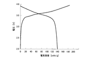
この全固体二次電池1を、例えば9個作製するとともに、それぞれ、0.1C、4~2Vで充放電させたところ、全て、異常なく充放電を行うことができた。その中の代表的な充放電曲線を図9に示す。この充放電曲線から、この全固体二次電池が正常に動作していることが分かった。なお、この全固体二次電池の押圧状態を感圧紙を介してみると、上記せん断ブロック部分が高圧力で押圧された状態であることが分かった。
比較例として、絶縁部材の接触内縁部を設けなかった電池を5個作製するとともに、これらについても、0.1C、4~2Vで充放電させたところ、4個が内部短絡(ショート)した。内部短絡しなかった残り1個についても、充電異常が発生した。
ところで、上記実施の形態においては、積層体の周囲に配置される絶縁部材の開口部の接触内縁部を厚くしたものとして説明したが、例えば図10に示すように、図7で示した負極集電体21側に、帯状の副絶縁部材41Bの外側に沿って配置し得る環状の外側絶縁部材42を、上部接着層52を介して接着させておき、そして押圧時に(矢印aで示す)、この外側絶縁部材42を、接着層54を介して、絶縁部材41の板状部41A(41a)の上面に接着させるようにしたものでもよい。言い換えると、絶縁部材41の全体の厚さを、押圧後における積層体Xの固体電解質層32の下面より上方の位置となるように厚くしたものである。
Claims (3)
- 一対の集電体の間に、正極層、固体電解質層および負極層が積層されてなる積層体、並びにこの積層体の周囲に配置されるとともに少なくとも固体電解質層と接触して正極層と負極層とを電気的に絶縁する板状の絶縁部材が配置された全固体二次電池であって、
上記絶縁部材における積層体との接触内縁部を外側の板状部よりも厚くしたことを特徴とする全固体二次電池。 - 一対の集電体の間に正極側接着層および負極側接着層を介して絶縁部材を配置するとともに、各接着層を絶縁部材の内方側端部からそれぞれ離すことにより、各集電体に歪吸収領域を具備させたことを特徴とする請求項1に記載の全固体二次電池。
- 一対の集電体の間に、正極層、固体電解質層および負極層が積層されてなる積層体、並びにこの積層体の周囲に配置されるとともに少なくとも固体電解質層と接触して正極層と負極層とを電気的に絶縁する板状の絶縁部材が配置された全固体二次電池の製造方法であって、
一方の集電体の表面に、正極層または負極層を案内し得る開口部を有し且つ当該開口部の内縁部が外側よりも厚くされた板状の絶縁部材を接着する工程と、
この工程で接着された絶縁部材の開口部内に正極層または負極層を配置する工程と、
この工程で配置された正極層または負極層の上面に固体電解質層を配置する工程と、
この工程で配置された固体電解質層の上面に負極層または正極層を配置して積層体を得る工程と、
この工程で得られた積層体の上面に、他方の集電体を配置した後、押圧する工程とを具備した特徴とする全固体二次電池の製造方法。
Priority Applications (4)
| Application Number | Priority Date | Filing Date | Title |
|---|---|---|---|
| US15/738,358 US10651506B2 (en) | 2015-06-23 | 2016-04-27 | All-solid-state secondary battery and method of producing the same |
| CN201680035240.2A CN107683543B (zh) | 2015-06-23 | 2016-04-27 | 全固态二次电池及其制造方法 |
| EP16814042.4A EP3316382B1 (en) | 2015-06-23 | 2016-04-27 | All-solid-state secondary battery and production method therefor |
| KR1020177035873A KR102508379B1 (ko) | 2015-06-23 | 2016-04-27 | 전고체 2차전지 및 그 제조방법 |
Applications Claiming Priority (2)
| Application Number | Priority Date | Filing Date | Title |
|---|---|---|---|
| JP2015-125202 | 2015-06-23 | ||
| JP2015125202A JP6608188B2 (ja) | 2015-06-23 | 2015-06-23 | 全固体二次電池およびその製造方法 |
Publications (1)
| Publication Number | Publication Date |
|---|---|
| WO2016208271A1 true WO2016208271A1 (ja) | 2016-12-29 |
Family
ID=57585518
Family Applications (1)
| Application Number | Title | Priority Date | Filing Date |
|---|---|---|---|
| PCT/JP2016/063132 Ceased WO2016208271A1 (ja) | 2015-06-23 | 2016-04-27 | 全固体二次電池およびその製造方法 |
Country Status (6)
| Country | Link |
|---|---|
| US (1) | US10651506B2 (ja) |
| EP (1) | EP3316382B1 (ja) |
| JP (1) | JP6608188B2 (ja) |
| KR (1) | KR102508379B1 (ja) |
| CN (1) | CN107683543B (ja) |
| WO (1) | WO2016208271A1 (ja) |
Cited By (3)
| Publication number | Priority date | Publication date | Assignee | Title |
|---|---|---|---|---|
| WO2018110688A1 (ja) * | 2016-12-16 | 2018-06-21 | 日立造船株式会社 | 全固体二次電池およびその製造方法 |
| WO2018214916A1 (zh) * | 2017-05-23 | 2018-11-29 | 辉能科技股份有限公司 | 电池结构 |
| WO2019131503A1 (ja) * | 2017-12-28 | 2019-07-04 | 日立造船株式会社 | 全固体電池、その製造方法および加工装置 |
Families Citing this family (21)
| Publication number | Priority date | Publication date | Assignee | Title |
|---|---|---|---|---|
| JP6726503B2 (ja) * | 2016-03-31 | 2020-07-22 | 日立造船株式会社 | 全固体二次電池およびその製造方法 |
| CN107305961B (zh) * | 2016-04-25 | 2022-03-29 | 松下知识产权经营株式会社 | 电池、电池制造方法和电池制造装置 |
| KR20190002492A (ko) * | 2016-04-26 | 2019-01-08 | 히다치 조센 가부시키가이샤 | 전고체 이차전지 |
| JP7157943B2 (ja) * | 2017-07-25 | 2022-10-21 | パナソニックIpマネジメント株式会社 | 電池 |
| JP6852713B2 (ja) * | 2018-05-09 | 2021-03-31 | トヨタ自動車株式会社 | 積層電池 |
| US12074284B2 (en) * | 2018-05-21 | 2024-08-27 | University Of Utah Research Foundation | Solid state battery cell having a composite solid electrolyte including lithium iron phosphate |
| JP7167488B2 (ja) | 2018-05-29 | 2022-11-09 | トヨタ自動車株式会社 | 正極、全固体電池及びこれらの製造方法 |
| CN112385069A (zh) * | 2018-07-13 | 2021-02-19 | 日立造船株式会社 | 全固态二次电池的制造设备 |
| JP2020061258A (ja) * | 2018-10-09 | 2020-04-16 | 本田技研工業株式会社 | 固体電池の製造方法 |
| JP7182159B2 (ja) * | 2018-12-12 | 2022-12-02 | パナソニックIpマネジメント株式会社 | 全固体電池 |
| JP7178633B2 (ja) | 2018-12-27 | 2022-11-28 | パナソニックIpマネジメント株式会社 | 全固体電池およびその製造方法 |
| US11056717B2 (en) | 2019-01-31 | 2021-07-06 | University Of Maryland, College Park | Lithium phosphate derivative compounds as Li super-ionic conductor, solid electrolyte and coating layer for lithium metal battery and lithium-ion battery |
| WO2020250981A1 (ja) * | 2019-06-13 | 2020-12-17 | 株式会社村田製作所 | 固体電池 |
| JP7150672B2 (ja) * | 2019-07-19 | 2022-10-11 | 本田技研工業株式会社 | 二次電池とその製造方法 |
| JP7465077B2 (ja) * | 2019-11-21 | 2024-04-10 | 太陽誘電株式会社 | 全固体電池とその製造方法 |
| JP7101655B2 (ja) * | 2019-12-16 | 2022-07-15 | 本田技研工業株式会社 | バッテリパック |
| KR20220027499A (ko) * | 2020-08-27 | 2022-03-08 | 삼성에스디아이 주식회사 | 전고체 이차전지 |
| WO2023017791A1 (ja) * | 2021-08-12 | 2023-02-16 | Tdk株式会社 | 全固体電池 |
| US11901564B2 (en) * | 2022-02-09 | 2024-02-13 | Socpra Sciences Et Génie S.E.C. | Anisotropic porous germanium nanostructures achieved with fast bipolar electrochemical etching and chemical etching |
| KR102457705B1 (ko) * | 2022-07-21 | 2022-10-21 | 부산대학교 산학협력단 | 전고체전지 단위셀 및 이의 제조방법 |
| JP7805895B2 (ja) * | 2022-08-26 | 2026-01-26 | 本田技研工業株式会社 | リチウム金属二次電池 |
Citations (3)
| Publication number | Priority date | Publication date | Assignee | Title |
|---|---|---|---|---|
| JP2014102982A (ja) * | 2012-11-20 | 2014-06-05 | Toyota Motor Corp | 全固体電池及びその製造方法 |
| JP2014222564A (ja) * | 2013-05-13 | 2014-11-27 | 日立造船株式会社 | 全固体電池並びに全固体電池の製造方法及び全固体電池の製造装置 |
| JP2016091750A (ja) * | 2014-11-04 | 2016-05-23 | 日立造船株式会社 | 全固体二次電池 |
Family Cites Families (9)
| Publication number | Priority date | Publication date | Assignee | Title |
|---|---|---|---|---|
| JPH0451455A (ja) * | 1990-06-18 | 1992-02-19 | Yuasa Corp | 薄形電池 |
| JPH0547360A (ja) * | 1991-08-09 | 1993-02-26 | Yuasa Corp | 薄形電池 |
| US5547780A (en) * | 1993-01-18 | 1996-08-20 | Yuasa Corporation | Battery precursor and a battery |
| JP5165843B2 (ja) * | 2004-12-13 | 2013-03-21 | パナソニック株式会社 | 活物質層と固体電解質層とを含む積層体およびこれを用いた全固体リチウム二次電池 |
| WO2010131321A1 (ja) * | 2009-05-11 | 2010-11-18 | トヨタ自動車株式会社 | 固体電池の製造方法及び固体電池 |
| JP5414371B2 (ja) | 2009-06-04 | 2014-02-12 | 出光興産株式会社 | 全固体リチウムイオン二次電池の製造方法 |
| WO2012124108A1 (ja) * | 2011-03-17 | 2012-09-20 | トヨタ自動車株式会社 | 固体電池、及び固体電池の製造方法 |
| JP6066574B2 (ja) * | 2012-03-05 | 2017-01-25 | 日立造船株式会社 | 全固体二次電池の製造方法 |
| JP5776722B2 (ja) * | 2013-04-24 | 2015-09-09 | 日産自動車株式会社 | 非水電解質二次電池 |
-
2015
- 2015-06-23 JP JP2015125202A patent/JP6608188B2/ja active Active
-
2016
- 2016-04-27 EP EP16814042.4A patent/EP3316382B1/en active Active
- 2016-04-27 US US15/738,358 patent/US10651506B2/en active Active
- 2016-04-27 WO PCT/JP2016/063132 patent/WO2016208271A1/ja not_active Ceased
- 2016-04-27 KR KR1020177035873A patent/KR102508379B1/ko active Active
- 2016-04-27 CN CN201680035240.2A patent/CN107683543B/zh active Active
Patent Citations (3)
| Publication number | Priority date | Publication date | Assignee | Title |
|---|---|---|---|---|
| JP2014102982A (ja) * | 2012-11-20 | 2014-06-05 | Toyota Motor Corp | 全固体電池及びその製造方法 |
| JP2014222564A (ja) * | 2013-05-13 | 2014-11-27 | 日立造船株式会社 | 全固体電池並びに全固体電池の製造方法及び全固体電池の製造装置 |
| JP2016091750A (ja) * | 2014-11-04 | 2016-05-23 | 日立造船株式会社 | 全固体二次電池 |
Non-Patent Citations (1)
| Title |
|---|
| See also references of EP3316382A4 * |
Cited By (10)
| Publication number | Priority date | Publication date | Assignee | Title |
|---|---|---|---|---|
| WO2018110688A1 (ja) * | 2016-12-16 | 2018-06-21 | 日立造船株式会社 | 全固体二次電池およびその製造方法 |
| JPWO2018110688A1 (ja) * | 2016-12-16 | 2019-10-24 | 日立造船株式会社 | 全固体二次電池およびその製造方法 |
| US11784353B2 (en) | 2016-12-16 | 2023-10-10 | Hitachi Zosen Corporation | All-solid state secondary cell and production method for the same |
| WO2018214916A1 (zh) * | 2017-05-23 | 2018-11-29 | 辉能科技股份有限公司 | 电池结构 |
| WO2019131503A1 (ja) * | 2017-12-28 | 2019-07-04 | 日立造船株式会社 | 全固体電池、その製造方法および加工装置 |
| CN111527638A (zh) * | 2017-12-28 | 2020-08-11 | 日立造船株式会社 | 全固态电池及其制造方法和加工装置 |
| JPWO2019131503A1 (ja) * | 2017-12-28 | 2020-12-17 | 日立造船株式会社 | 全固体電池、その製造方法および加工装置 |
| JP7082142B2 (ja) | 2017-12-28 | 2022-06-07 | 日立造船株式会社 | 全固体電池、その製造方法および加工装置 |
| CN111527638B (zh) * | 2017-12-28 | 2024-09-20 | 日立造船株式会社 | 全固态电池的制造方法 |
| US12424655B2 (en) | 2017-12-28 | 2025-09-23 | Kanadevia Corporation | All-solid-state battery, method for manufacturing same, and processing device |
Also Published As
| Publication number | Publication date |
|---|---|
| JP6608188B2 (ja) | 2019-11-20 |
| EP3316382A4 (en) | 2018-05-02 |
| JP2017010786A (ja) | 2017-01-12 |
| KR102508379B1 (ko) | 2023-03-08 |
| KR20180020150A (ko) | 2018-02-27 |
| CN107683543A (zh) | 2018-02-09 |
| CN107683543B (zh) | 2020-03-27 |
| US20180198169A1 (en) | 2018-07-12 |
| US10651506B2 (en) | 2020-05-12 |
| EP3316382A1 (en) | 2018-05-02 |
| EP3316382B1 (en) | 2019-10-02 |
Similar Documents
| Publication | Publication Date | Title |
|---|---|---|
| JP6608188B2 (ja) | 全固体二次電池およびその製造方法 | |
| JP7780774B2 (ja) | 電池 | |
| CN110073539B (zh) | 全固态二次电池及其制造方法 | |
| EP2966721B1 (en) | Non-aqueous electrolyte secondary battery | |
| CN110416629B (zh) | 全固体电池 | |
| JP6576072B2 (ja) | 全固体二次電池の製造方法 | |
| JP6726503B2 (ja) | 全固体二次電池およびその製造方法 | |
| JP6324296B2 (ja) | 全固体二次電池 | |
| JP2020013729A (ja) | 直列積層型全固体電池の製造方法 | |
| WO2017187494A1 (ja) | 全固体二次電池 | |
| KR102403673B1 (ko) | 전극 조립체, 이를 포함하는 이차 전지 및 전극 조립체의 제조 방법 | |
| CN110114931B (zh) | 全固态电池的制造方法及其制造装置 | |
| JP7826322B2 (ja) | 全固体電池 | |
| US20240120552A1 (en) | Sulfide Solid-State Battery, Printed Circuit Board with Sulfide Solid-State Battery, and Manufacturing Method of Sulfide Solid-State Battery | |
| TW202515005A (zh) | 固態電池單元、固態電池堆、固態電池組、固態電池單元的製造方法及固態電池堆的製造方法 | |
| WO2022191235A1 (ja) | 全固体電池 |
Legal Events
| Date | Code | Title | Description |
|---|---|---|---|
| 121 | Ep: the epo has been informed by wipo that ep was designated in this application |
Ref document number: 16814042 Country of ref document: EP Kind code of ref document: A1 |
|
| ENP | Entry into the national phase |
Ref document number: 20177035873 Country of ref document: KR Kind code of ref document: A |
|
| NENP | Non-entry into the national phase |
Ref country code: DE |
|
| WWE | Wipo information: entry into national phase |
Ref document number: 2016814042 Country of ref document: EP |