WO2016208324A1 - ガス拡散電極基材およびその製造方法、ガス拡散電極、膜電極接合体ならびに固体高分子形燃料電池 - Google Patents
ガス拡散電極基材およびその製造方法、ガス拡散電極、膜電極接合体ならびに固体高分子形燃料電池 Download PDFInfo
- Publication number
- WO2016208324A1 WO2016208324A1 PCT/JP2016/065725 JP2016065725W WO2016208324A1 WO 2016208324 A1 WO2016208324 A1 WO 2016208324A1 JP 2016065725 W JP2016065725 W JP 2016065725W WO 2016208324 A1 WO2016208324 A1 WO 2016208324A1
- Authority
- WO
- WIPO (PCT)
- Prior art keywords
- gas diffusion
- diffusion electrode
- carbon fiber
- electrode substrate
- nonwoven fabric
- Prior art date
- Legal status (The legal status is an assumption and is not a legal conclusion. Google has not performed a legal analysis and makes no representation as to the accuracy of the status listed.)
- Ceased
Links
Images

Classifications
-
- H—ELECTRICITY
- H01—ELECTRIC ELEMENTS
- H01M—PROCESSES OR MEANS, e.g. BATTERIES, FOR THE DIRECT CONVERSION OF CHEMICAL ENERGY INTO ELECTRICAL ENERGY
- H01M4/00—Electrodes
- H01M4/86—Inert electrodes with catalytic activity, e.g. for fuel cells
- H01M4/88—Processes of manufacture
- H01M4/8803—Supports for the deposition of the catalytic active composition
- H01M4/8807—Gas diffusion layers
-
- H—ELECTRICITY
- H01—ELECTRIC ELEMENTS
- H01M—PROCESSES OR MEANS, e.g. BATTERIES, FOR THE DIRECT CONVERSION OF CHEMICAL ENERGY INTO ELECTRICAL ENERGY
- H01M4/00—Electrodes
- H01M4/86—Inert electrodes with catalytic activity, e.g. for fuel cells
- H01M4/88—Processes of manufacture
- H01M4/8817—Treatment of supports before application of the catalytic active composition
- H01M4/8821—Wet proofing
-
- H—ELECTRICITY
- H01—ELECTRIC ELEMENTS
- H01M—PROCESSES OR MEANS, e.g. BATTERIES, FOR THE DIRECT CONVERSION OF CHEMICAL ENERGY INTO ELECTRICAL ENERGY
- H01M8/00—Fuel cells; Manufacture thereof
- H01M8/02—Details
- H01M8/0202—Collectors; Separators, e.g. bipolar separators; Interconnectors
- H01M8/023—Porous and characterised by the material
- H01M8/0234—Carbonaceous material
-
- D—TEXTILES; PAPER
- D04—BRAIDING; LACE-MAKING; KNITTING; TRIMMINGS; NON-WOVEN FABRICS
- D04H—MAKING TEXTILE FABRICS, e.g. FROM FIBRES OR FILAMENTARY MATERIAL; FABRICS MADE BY SUCH PROCESSES OR APPARATUS, e.g. FELTS, NON-WOVEN FABRICS; COTTON-WOOL; WADDING ; NON-WOVEN FABRICS FROM STAPLE FIBRES, FILAMENTS OR YARNS, BONDED WITH AT LEAST ONE WEB-LIKE MATERIAL DURING THEIR CONSOLIDATION
- D04H1/00—Non-woven fabrics formed wholly or mainly of staple fibres or like relatively short fibres
- D04H1/40—Non-woven fabrics formed wholly or mainly of staple fibres or like relatively short fibres from fleeces or layers composed of fibres without existing or potential cohesive properties
- D04H1/42—Non-woven fabrics formed wholly or mainly of staple fibres or like relatively short fibres from fleeces or layers composed of fibres without existing or potential cohesive properties characterised by the use of certain kinds of fibres insofar as this use has no preponderant influence on the consolidation of the fleece
- D04H1/4209—Inorganic fibres
- D04H1/4242—Carbon fibres
-
- D—TEXTILES; PAPER
- D06—TREATMENT OF TEXTILES OR THE LIKE; LAUNDERING; FLEXIBLE MATERIALS NOT OTHERWISE PROVIDED FOR
- D06C—FINISHING, DRESSING, TENTERING OR STRETCHING TEXTILE FABRICS
- D06C15/00—Calendering, pressing, ironing, glossing or glazing textile fabrics
- D06C15/10—Calendering, pressing, ironing, glossing or glazing textile fabrics between flat plates of a press
-
- D—TEXTILES; PAPER
- D06—TREATMENT OF TEXTILES OR THE LIKE; LAUNDERING; FLEXIBLE MATERIALS NOT OTHERWISE PROVIDED FOR
- D06C—FINISHING, DRESSING, TENTERING OR STRETCHING TEXTILE FABRICS
- D06C23/00—Making patterns or designs on fabrics
-
- H—ELECTRICITY
- H01—ELECTRIC ELEMENTS
- H01M—PROCESSES OR MEANS, e.g. BATTERIES, FOR THE DIRECT CONVERSION OF CHEMICAL ENERGY INTO ELECTRICAL ENERGY
- H01M4/00—Electrodes
- H01M4/86—Inert electrodes with catalytic activity, e.g. for fuel cells
-
- H—ELECTRICITY
- H01—ELECTRIC ELEMENTS
- H01M—PROCESSES OR MEANS, e.g. BATTERIES, FOR THE DIRECT CONVERSION OF CHEMICAL ENERGY INTO ELECTRICAL ENERGY
- H01M4/00—Electrodes
- H01M4/86—Inert electrodes with catalytic activity, e.g. for fuel cells
- H01M4/88—Processes of manufacture
- H01M4/8875—Methods for shaping the electrode into free-standing bodies, like sheets, films or grids, e.g. moulding, hot-pressing, casting without support, extrusion without support
-
- H—ELECTRICITY
- H01—ELECTRIC ELEMENTS
- H01M—PROCESSES OR MEANS, e.g. BATTERIES, FOR THE DIRECT CONVERSION OF CHEMICAL ENERGY INTO ELECTRICAL ENERGY
- H01M4/00—Electrodes
- H01M4/86—Inert electrodes with catalytic activity, e.g. for fuel cells
- H01M4/88—Processes of manufacture
- H01M4/8878—Treatment steps after deposition of the catalytic active composition or after shaping of the electrode being free-standing body
- H01M4/8882—Heat treatment, e.g. drying, baking
- H01M4/8885—Sintering or firing
-
- H—ELECTRICITY
- H01—ELECTRIC ELEMENTS
- H01M—PROCESSES OR MEANS, e.g. BATTERIES, FOR THE DIRECT CONVERSION OF CHEMICAL ENERGY INTO ELECTRICAL ENERGY
- H01M4/00—Electrodes
- H01M4/86—Inert electrodes with catalytic activity, e.g. for fuel cells
- H01M4/96—Carbon-based electrodes
-
- H—ELECTRICITY
- H01—ELECTRIC ELEMENTS
- H01M—PROCESSES OR MEANS, e.g. BATTERIES, FOR THE DIRECT CONVERSION OF CHEMICAL ENERGY INTO ELECTRICAL ENERGY
- H01M8/00—Fuel cells; Manufacture thereof
- H01M8/02—Details
- H01M8/0202—Collectors; Separators, e.g. bipolar separators; Interconnectors
- H01M8/0247—Collectors; Separators, e.g. bipolar separators; Interconnectors characterised by the form
-
- H—ELECTRICITY
- H01—ELECTRIC ELEMENTS
- H01M—PROCESSES OR MEANS, e.g. BATTERIES, FOR THE DIRECT CONVERSION OF CHEMICAL ENERGY INTO ELECTRICAL ENERGY
- H01M8/00—Fuel cells; Manufacture thereof
- H01M8/10—Fuel cells with solid electrolytes
- H01M8/1004—Fuel cells with solid electrolytes characterised by membrane-electrode assemblies [MEA]
-
- H—ELECTRICITY
- H01—ELECTRIC ELEMENTS
- H01M—PROCESSES OR MEANS, e.g. BATTERIES, FOR THE DIRECT CONVERSION OF CHEMICAL ENERGY INTO ELECTRICAL ENERGY
- H01M8/00—Fuel cells; Manufacture thereof
- H01M8/10—Fuel cells with solid electrolytes
- H01M8/1016—Fuel cells with solid electrolytes characterised by the electrolyte material
- H01M8/1018—Polymeric electrolyte materials
-
- D—TEXTILES; PAPER
- D10—INDEXING SCHEME ASSOCIATED WITH SUBLASSES OF SECTION D, RELATING TO TEXTILES
- D10B—INDEXING SCHEME ASSOCIATED WITH SUBLASSES OF SECTION D, RELATING TO TEXTILES
- D10B2101/00—Inorganic fibres
- D10B2101/10—Inorganic fibres based on non-oxides other than metals
- D10B2101/12—Carbon; Pitch
-
- H—ELECTRICITY
- H01—ELECTRIC ELEMENTS
- H01M—PROCESSES OR MEANS, e.g. BATTERIES, FOR THE DIRECT CONVERSION OF CHEMICAL ENERGY INTO ELECTRICAL ENERGY
- H01M8/00—Fuel cells; Manufacture thereof
- H01M8/10—Fuel cells with solid electrolytes
- H01M2008/1095—Fuel cells with polymeric electrolytes
-
- Y—GENERAL TAGGING OF NEW TECHNOLOGICAL DEVELOPMENTS; GENERAL TAGGING OF CROSS-SECTIONAL TECHNOLOGIES SPANNING OVER SEVERAL SECTIONS OF THE IPC; TECHNICAL SUBJECTS COVERED BY FORMER USPC CROSS-REFERENCE ART COLLECTIONS [XRACs] AND DIGESTS
- Y02—TECHNOLOGIES OR APPLICATIONS FOR MITIGATION OR ADAPTATION AGAINST CLIMATE CHANGE
- Y02E—REDUCTION OF GREENHOUSE GAS [GHG] EMISSIONS, RELATED TO ENERGY GENERATION, TRANSMISSION OR DISTRIBUTION
- Y02E60/00—Enabling technologies; Technologies with a potential or indirect contribution to GHG emissions mitigation
- Y02E60/30—Hydrogen technology
- Y02E60/50—Fuel cells
-
- Y—GENERAL TAGGING OF NEW TECHNOLOGICAL DEVELOPMENTS; GENERAL TAGGING OF CROSS-SECTIONAL TECHNOLOGIES SPANNING OVER SEVERAL SECTIONS OF THE IPC; TECHNICAL SUBJECTS COVERED BY FORMER USPC CROSS-REFERENCE ART COLLECTIONS [XRACs] AND DIGESTS
- Y02—TECHNOLOGIES OR APPLICATIONS FOR MITIGATION OR ADAPTATION AGAINST CLIMATE CHANGE
- Y02P—CLIMATE CHANGE MITIGATION TECHNOLOGIES IN THE PRODUCTION OR PROCESSING OF GOODS
- Y02P70/00—Climate change mitigation technologies in the production process for final industrial or consumer products
- Y02P70/50—Manufacturing or production processes characterised by the final manufactured product
Definitions
- the present invention relates to a gas diffusion electrode substrate for a polymer electrolyte fuel cell and a method for producing the same.
- the gas diffusion electrode when the gas diffusion electrode is densified for the purpose of increasing the conductivity and thermal conductivity, the diffusion of hydrogen and air necessary for the reaction may be insufficient. In addition, it may be difficult to obtain high power generation efficiency due to the generation of so-called flooding in which water generated by the reaction closes the gaps in the catalyst layer and the gas diffusion electrode and hinders the transport of hydrogen and air. On the other hand, high power generation efficiency cannot be obtained even when the humidification is insufficient and the ionomer of the electrolyte membrane or the catalyst layer is dried, that is, when dryout occurs.
- Non-Patent Document 1 describes that by making a wall surface of a gas flow path hydrophilic, liquid water spreads in a film shape and does not hinder the supply of oxygen.
- Patent Document 1 it is possible to supply gas to a portion (rib portion) where gas does not flow by grooving carbon fiber paper or carbon cloth and arranging the groove in a direction different from the gas flow path formed in the separator. And a technique for facilitating the supply of the reaction gas and the removal of the reaction product.
- Patent Document 2 a sinusoidal groove is formed on a sheet made of carbon fiber by a water jet punching method, and then a binder resin is baked to obtain a gas diffusion electrode, which is connected to a gas flow path formed in a separator.
- Techniques for controlling the removal and moisturization of reaction products by direction are disclosed.
- Patent Documents 3 and 4 disclose techniques for obtaining a gas diffusion electrode by pressing a polyacrylonitrile-based oxidized fiber sheet with a grooved roller to form a groove, and simultaneously or subsequently firing the groove.
- the hydrophilized gas flow path described in Non-Patent Document 1 has the effect of not hindering the gas supply in the gas flow direction, but the drainage in the gas diffusion electrode and on the surface of the gas diffusion electrode is not sufficient.
- An object of the present invention is to provide a gas diffusion electrode substrate capable of satisfactorily performing both the supply of a reaction gas to the gas diffusion electrode and the discharge of water as a reaction product.
- the present invention provides a gas obtained by applying a water repellent to a carbon fiber nonwoven fabric in which discontinuous protrusions are dispersedly formed at 30 / cm 2 to 5000 / cm 2 on at least one surface. It is a diffusion electrode substrate.
- the gas diffusion electrode substrate of the present invention can perform both the supply of the reaction gas to the gas diffusion electrode and the discharge of water as the reaction product.
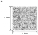
- FIG. 2 is an optical micrograph (high magnification) of the surface of the gas diffusion electrode substrate of the present invention obtained in Example 1.
- FIG. 2 is an optical micrograph (low magnification) of the surface of the gas diffusion electrode substrate of the present invention obtained in Example 1.
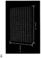
- FIG. 2 is an optical micrograph of the surface of a shaping member having a recess used in Example 1.
- the gas diffusion electrode substrate of the present invention is obtained by adding a water repellent to a carbon fiber nonwoven fabric having discontinuous protrusions.
- the carbon fiber nonwoven fabric is obtained by heating and carbonizing a carbon fiber precursor fiber nonwoven fabric in an inert gas atmosphere.
- Carbon fiber is a carbon fiber precursor fiber that is carbonized by heating in an inert gas atmosphere.
- Non-woven fabric is a method in which the constituent fibers of the web are mechanically entangled, fused by heating, and bonded by a binder. It is fixed.
- the web is a sheet formed by laminating carbon fiber precursor fibers.
- the carbon fiber nonwoven fabric used in the present invention is preferably made of carbon fibers having a fiber length exceeding 3 mm.
- the fiber length of the carbon fiber exceeds 10 mm.
- the upper limit of fiber length is not specifically limited, Generally it is preferable that it is 100 mm or less.
- fiber length shall mean a number average fiber length.
- the fiber diameter of the carbon fiber is preferably 3 to 30 ⁇ m, more preferably 5 to 20 ⁇ m.
- the average pore diameter of the carbon fiber nonwoven fabric is preferably 20 ⁇ m or more, more preferably 25 ⁇ m or more, and further preferably 30 ⁇ m or more. Moreover, although an upper limit is not specifically limited, 80 micrometers or less are preferable and 70 micrometers or less are more preferable. When the average pore diameter is 20 ⁇ m or more, high performance can be obtained by gas diffusion and drainage. Moreover, if the average pore diameter is 80 ⁇ m or less, it is easy to prevent dryout.
- the average pore diameter of the carbon fiber nonwoven fabric refers to a value measured by a mercury intrusion method. This can be measured using, for example, PoreMaster (manufactured by Quantachrome), etc. In the present invention, the value calculated by assuming that the surface tension ⁇ of mercury is 480 dyn / cm and the contact angle between mercury and the carbon fiber nonwoven fabric is 140 °. Use.
- the gas diffusion electrode substrate is preferably thin as long as it exhibits its function, and is generally about 30 ⁇ m to 500 ⁇ m.
- the thickness of the gas diffusion electrode substrate is preferably 300 ⁇ m or less, more preferably 250 ⁇ m or less, and even more preferably 200 ⁇ m or less. Further, the thickness of the gas diffusion electrode substrate is more preferably 50 ⁇ m or more, and further preferably 70 ⁇ m or more. If the thickness of the gas diffusion electrode base material is 50 ⁇ m or more, gas diffusion in the in-plane direction is further improved and gas can be easily supplied to the catalyst under the ribs of the separator. The power generation performance is further improved.
- the thickness of the gas diffusion electrode substrate is 300 ⁇ m or less, the gas diffusion path and drainage path are shortened, and the conductivity and thermal conductivity can be increased, and the power generation performance is improved at both high and low temperatures. improves.
- the thickness of the gas diffusion electrode substrate is a thickness measured in a state where an area of ⁇ 5 mm or more is pressed at a surface pressure of 0.15 MPa.
- the thickness of the gas diffusion electrode base material in which the microporous layer described later is formed means the thickness including the microporous layer.
- the basis weight of the carbon fiber nonwoven fabric is not particularly limited, but is preferably 15 g / m 2 or more, and more preferably 20 g / m 2 or more. By setting it as 15 g / m ⁇ 2 > or more, mechanical strength improves and the conveyance property in a manufacturing process can be made favorable.
- the basis weight is preferably 150 g / m 2 or less, and more preferably 120 g / m 2 or less. By setting it to 150 g / m 2 or less, the gas permeation diffusivity in the direction perpendicular to the surface of the carbon fiber nonwoven fabric is further improved.
- the apparent density of the carbon fiber nonwoven fabric is preferably 0.10 to 1.00 g / cm 3 .
- the apparent density is more preferably 0.20 to 0.80 g / cm 3 , further preferably 0.25 to 0.60 g / cm 3 .
- the apparent density is obtained by dividing the basis weight by the thickness.
- a method for applying such a binder include a method in which a carbon fiber non-woven fabric after carbonization is impregnated or sprayed with a binder solution, and heat-treated again under an inert atmosphere to carbonize the binder.
- a thermosetting resin such as a phenol resin, an epoxy resin, a melamine resin, or a furan resin can be used, and among them, the phenol resin is particularly preferable in terms of a high carbonization yield.
- thermoplastic resin is mixed with a carbon fiber precursor nonwoven fabric
- the carbon fibers are easy to move, so that there is an advantage that they are flexible and easy to handle in the manufacturing process.
- a carbon fiber nonwoven fabric having a plurality of non-continuous protrusions dispersed on the surface is used.
- a discontinuous protrusion shall mean the convex part which is not continuous from the one end of a carbon fiber nonwoven fabric to the other end.
- the convex portion does not become an obstacle to the supply of the reaction gas and the discharge of water, and both the supply of the reaction gas and the discharge of water can be performed satisfactorily.
- being dispersedly formed means a state in which a plurality of non-continuous protrusions are arranged on the surface of the carbon fiber nonwoven fabric without the peripheries of the non-continuous protrusions contacting each other.
- the arrangement pattern of the plurality of non-continuous protrusions is not particularly limited, but the discontinuous protrusions are preferably formed so as to be distributed substantially uniformly in the plane.
- the plurality of non-continuous protrusions are preferably formed isotropically on the surface of the carbon fiber nonwoven fabric, and more preferably formed in the form of isotropic and equally spaced dots.
- isotropic means that the distribution of non-continuous protrusions does not change by rotation of 90 degrees, and in particular, when the carbon fiber nonwoven fabric is square in plan view, This means that the discontinuous protrusion formation patterns are the same when viewed from the side.
- discontinuous protrusions are present in the vicinity of the reaction gas inlet because the reaction product water droplets are small and the reaction gas concentration is high. It is also a preferable aspect that the discontinuous protrusions are arranged sparsely because the water droplets are large and the reaction gas concentration is low near the outlet of the reaction gas.
- the number of discontinuous protrusions per unit area of the carbon fiber nonwoven fabric is 30 / cm 2 to 5000 / cm 2 , and more preferably 100 / cm 2 to 1500 / cm 2 .
- the number of non-continuous projections 30 / cm 2 or more, a relatively small water droplets easily move with the gas flow path of the top surface of the non-continuous projection and the bottom surface, the 5000 / cm 2 or less, mutual projections and water droplets This is because it is easy to reduce the action.
- the description of the non-continuous protrusion in the present specification excludes the influence of surface unevenness due to the carbon fiber itself. Assuming that the discontinuous projection surface of the carbon fiber nonwoven fabric was trimmed until it became the same thickness as the thickness of the carbon fiber nonwoven fabric when pressurized at 1 MPa (hereinafter, sometimes referred to simply as “thickness during pressurization”). It shall be a depiction of the shape of the case.
- Thickness at the time of pressurization is a pressure of 1 MPa against the carbon fiber nonwoven fabric by sandwiching a carbon fiber nonwoven fabric cut to 2.5 cm ⁇ 2.5 cm with a metal plate having a surface of 3 cm or more ⁇ 3 cm or more and a thickness of 1 cm or more. Shall be obtained.
- the discontinuous protrusion formation surface of the carbon fiber nonwoven fabric is trimmed until the thickness becomes the same as the thickness at the time of pressurization, the discontinuous protrusion disappears or cannot be recognized as the discontinuous protrusion. Assume that no protrusion is formed.
- the cross-sectional shape of the discontinuous protrusion is not particularly limited, and can be any shape such as a circle, an ellipse, a donut shape, a rectangle, a triangle, a polygon, and a star shape. You can choose.
- the vertical cross-sectional shape of the non-continuous protrusion (the cross-sectional shape when cut by a plane perpendicular to the surface of the carbon fiber nonwoven fabric) is not particularly limited, and even if it is a substantially square whose size does not change in the height direction, although it may be a substantially trapezoidal shape, a substantially triangular shape, or a substantially arc shape whose size changes, a trapezoidal shape or a bow shape whose width becomes narrower as the height increases is preferable in that drainage efficiency can be improved. From the viewpoint of ease of formation, it is most preferable that the non-continuous protrusion has an arcuate shape with a lower cross section in the height direction.
- the size of the discontinuous protrusion should be adjusted as appropriate in relation to the size of the gas flow path formed in the separator.
- the diameter of the minimum circumscribed circle on the top surface of one discontinuous protrusion is preferably 1 cm or less.
- the top surface of the discontinuous protrusion means a cut surface of the discontinuous protrusion by the trimming surface having a thickness when pressed.
- the diameter of the minimum circumscribed circle on the top surface of one discontinuous protrusion is more preferably 5 mm or less, and further preferably 1 mm or less.
- the diameter of the maximum inscribed circle of one non-continuous protrusion is preferably 50 ⁇ m or more, and more preferably 100 ⁇ m or more.
- Area of the top face of one non-continuous projection from the viewpoint of ensuring conductivity, preferably at 1000 .mu.m 2 or more, and more preferably 2000 .mu.m 2 or more. Further, from the viewpoint of ensuring drainage, it is preferably 100 mm 2 or less, more preferably 10 mm 2 or less, and even more preferably 1 mm 2 or less.
- the peripheral length of the top surface of the discontinuous protrusion existing per unit area is preferably 0.1 to 20 km / m 2 , and more preferably 0.5 to 10 km / m 2 . This is because a high drainage effect is obtained when the peripheral length of the top surface is 0.1 km / m 2 or more, and the supply of the reaction gas is facilitated when it is 10 km / m 2 or less.
- the height of the discontinuous protrusion is preferably 5 ⁇ m or more and 250 ⁇ m or less. When the height of the discontinuous protrusion is within the range, it is possible to achieve both gas supply uniformity and water discharge performance while maintaining the strength of the carbon fiber nonwoven fabric.
- the height of the discontinuous protrusion is more preferably 10 ⁇ m or more, and further preferably 15 ⁇ m or more. Moreover, it is more preferable that it is 200 micrometers or less, and it is further more preferable that it is 150 micrometers or less. Further, from the viewpoint of securing drainage, the height of the discontinuous protrusion is preferably 5% or more, more preferably 10% or more, with respect to the thickness of the carbon fiber nonwoven fabric when pressed.
- the height of the non-continuous protrusion is observed with a laser microscope or the like, and using the shape analysis application, the non-protrusion forming surface of the non-continuous protrusion and the opening surface corresponding to the thickness when the carbon fiber nonwoven fabric is pressed are opened. It can be obtained by measuring the height of the plane (top surface) existing on the side.
- the discontinuous protrusions are preferably formed in the form of isotropic and equally spaced dots on the surface of the carbon fiber nonwoven fabric.
- the pitch of the discontinuous protrusions is preferably 1 mm or less, and more preferably 0.8 mm or less. Further, the pitch of the discontinuous protrusions is preferably 0.1 mm or more, and more preferably 0.2 mm or more.
- the carbon fiber nonwoven fabric it is preferable that no broken fiber is observed on the wall surface of the discontinuous protrusion in a plan view. Due to the absence of broken fibers, high conductivity is obtained.
- the fact that broken fibers are not observed on the walls of the non-continuous protrusions means that the surface of the carbon fiber nonwoven fabric is observed with an optical microscope, an electron microscope, etc., and oriented around the non-continuous protrusions from the outside to the inside of the non-continuous protrusions. This can be confirmed by not observing carbon fibers that are discontinuous on the wall surfaces of the discontinuous protrusions.
- the number of discontinuous protrusions in which no fracture fibers are observed on the wall surfaces of the discontinuous protrusions is larger than the number of discontinuous protrusions in which fracture fibers are observed on the wall surfaces of the discontinuous protrusions. It is assumed that no broken fiber is observed on the wall of the discontinuous protrusion. There may be a case where it is impossible to strictly distinguish the broken portion of the broken fiber and the end portion of the fiber that has not been broken. In this case, the latter is included in the former.
- non-continuous protrusions since a large number of non-continuous protrusions are usually formed, in the present invention, 20 or more adjacent non-continuous protrusions are observed, and in the case where a fracture fiber is not observed on the wall surface of the majority of the non-continuous protrusions, It is determined that the number of non-continuous protrusions on which the broken fibers are not observed on the wall surfaces of the non-continuous protrusions is greater than the number of non-continuous protrusions on which the broken fibers are observed on the wall surfaces of the non-continuous protrusions.
- Such non-continuous protrusions in which no broken fiber is observed on the wall surface are preferably present in an amount of 70% or more, more preferably 80% or more, and even more preferably 90% or more of all the discontinuous protrusions.
- the carbon fiber nonwoven fabric it is preferable that at least some of the carbon fibers constituting the wall surface of the discontinuous protrusion are oriented in the height direction of the discontinuous protrusion.
- the carbon fiber constituting the wall surface of the discontinuous protrusion is a carbon fiber in which at least a part of the fiber is exposed on the wall surface of the discontinuous protrusion. And the said carbon fiber is orientating in the height direction of a discontinuous protrusion, When a discontinuous protrusion is divided into 3 equally in a height direction, carbon fiber will be divided into two equal surfaces (carbon fiber nonwoven fabric bottom face). And a plane parallel to each other).
- the contact area with the gas supply side member (for example, a separator) is smaller than when the protrusion is not formed, and the conductivity and thermal conductivity are lowered.
- carbon fibers are superior in conductivity and thermal conductivity in the fiber axis direction than in the fiber cross-sectional direction, so the carbon fibers constituting the wall surfaces of the discontinuous protrusions are oriented in the height direction of the discontinuous protrusions. If so, the conductivity and thermal conductivity in the thickness direction of the carbon fiber nonwoven fabric can be improved, and the decrease in conductivity and thermal conductivity due to hole formation can be compensated.
- the presence of carbon fibers oriented in the height direction of the discontinuous protrusion is observed by observing the surface of the carbon fiber nonwoven fabric with a laser microscope or the like, and using the shape analysis application, etc. Carbon fiber that crosses both the line of intersection between the dividing surface and the inner wall of the discontinuous protrusion, and the line of intersection between each divide height of the discontinuous protrusion and the inner wall of the discontinuous protrusion is observed. Can be confirmed.
- a carbon fiber nonwoven fabric that crosses the discontinuous protrusions at positions 1/3 and 2/3 of the height of the discontinuous protrusions by observing an arbitrary cross section including the discontinuous protrusions of the carbon fiber nonwoven fabric with a scanning electron microscope or the like. This can also be confirmed by drawing two straight lines parallel to the surface and observing carbon fibers that intersect both of the two straight lines. Two or more such carbon fibers are preferably present in one non-continuous protrusion, and more preferably five or more.
- the effect of improving the conductivity and thermal conductivity in the height direction of the discontinuous protrusions Is preferable because of high.
- the carbon fiber is continuous up to the top surface of the discontinuous protrusion, that the tip of the carbon fiber nonwoven fabric top surface side of the carbon fiber constituting the wall surface of the discontinuous protrusion is bent or curved, It refers to a state in which at least a part is also exposed on the top surface of the discontinuous protrusion.
- At least some of the carbon fibers constituting one wall surface of the non-continuous protrusion are continuous to the top surface of the non-continuous protrusion, and other wall surfaces are also formed. It is preferable to comprise. That is, it is preferable that there are carbon fibers that form a wall surface at two locations in the discontinuous protrusion and continue to the top surface.
- Water repellent Generally, in a gas diffusion electrode substrate, hydrophilic treatment is often performed on the gas flow path so as not to prevent gas supply. However, the gas diffusion electrode substrate of the present invention has a discontinuous protrusion. From the viewpoint of reducing the water transfer resistance on the top surface of the carbon fiber, a water repellent is applied to the carbon fiber nonwoven fabric as described above. As the water repellent, it is preferable to use a fluorine-based polymer because of its excellent corrosion resistance.
- fluorine-based polymer examples include polytetrafluoroethylene (PTFE), tetrafluoroethylene-hexafluoropropylene copolymer (FEP), and tetrafluoroethylene-perfluoroalkyl vinyl ether copolymer (PFA).
- PTFE polytetrafluoroethylene
- FEP tetrafluoroethylene-hexafluoropropylene copolymer
- PFA tetrafluoroethylene-perfluoroalkyl vinyl ether copolymer
- the contact angle when a 10 ⁇ L water droplet is placed on the surface of the carbon fiber nonwoven fabric is over 120 °, it is determined that the water repellent is applied.
- a fluorine-based polymer used as the water repellent, it is confirmed by X-ray spectroscopy that fluorine atoms are present on the surface of the fibers constituting the carbon fiber nonwoven fabric, or thermogravimetry and mass measurement are performed. By detecting the fluorocarbon by the combined TG-MS, it can be confirmed that the water repellent is provided.
- the content of the water repellent in the gas diffusion electrode substrate is not particularly limited, but is preferably 1% by mass to 20% by mass, and more preferably 3% by mass to 10% by mass with respect to the carbon fiber nonwoven fabric.
- the water repellent material may contain other additives.
- the inclusion of conductive carbon particles is a preferred embodiment because both water repellency and conductivity can be achieved.
- the gas diffusion electrode substrate of the present invention may further have a microporous layer.
- the microporous layer is a layer containing a carbon material formed on the surface in contact with the catalyst layer in the gas diffusion electrode, and is provided on the surface where no discontinuous protrusion is formed, that is, the bottom surface of the carbon fiber nonwoven fabric.
- the microporous layer suppresses flooding by promoting the exclusion of water from between the catalyst layer and the carbon fiber nonwoven fabric, and also promotes the reverse diffusion of moisture into the electrolyte membrane and suppresses dry-up.
- Examples of the carbon material constituting the microporous layer include carbon black such as furnace black, acetylene black, lamp black, and thermal black, scaly graphite, scaly graphite, earth graphite, artificial graphite, expanded graphite, and flake graphite.
- linear carbon such as vapor grown carbon fiber, single-walled carbon nanotube, double-walled carbon nanotube, multi-walled carbon nanotube, carbon nanohorn, carbon nanocoil, cup-stacked carbon nanotube, bamboo-like carbon nanotube, and graphite nanofiber is preferably used. It is done.
- the microporous layer preferably contains a water repellent.
- a water repellent it is preferable to use a fluorine-based polymer having high corrosion resistance.
- the fluorine-based polymer include polytetrafluoroethylene (PTFE), tetrafluoroethylene-hexafluoropropylene copolymer (FEP), and tetrafluoroethylene-perfluoroalkyl vinyl ether copolymer (PFA).
- the porosity of the microporous layer is preferably in the range of 60 to 85%, more preferably in the range of 65 to 80%, and still more preferably in the range of 70 to 75%.
- the porosity is 60% or more, drainage is further improved, and flooding can be further suppressed. Further, when the porosity is 85% or less, the water vapor diffusibility is smaller, and the dry-up can be further suppressed.
- the porosity of the microporous layer is measured by using a sample for cross-sectional observation using an ion beam cross-section processing apparatus, and taking a photograph with a microscope such as a scanning electron microscope with a cross-section magnified 1000 times or more. The area of the portion was measured, and the ratio of the area of the void portion to the observation area was obtained.
- the microporous layer having such a porosity can be obtained by controlling the basis weight of the microporous layer, the water repellent, the blending amount of the carbon material with respect to other materials, the type of the carbon material, and the thickness of the microporous layer. Among them, it is effective to control the blending amount of the carbon material relative to the water repellent and other materials and the type of the carbon material.
- a microporous layer having a high porosity can be obtained by increasing the blending amount of the carbon material relative to the water repellent and other materials, and a microporous layer having a low porosity can be obtained by decreasing the amount.
- the basis weight of the microporous layer is preferably in the range of 10 to 35 g / m 2 .
- the basis weight of the microporous layer is 10 g / m 2 or more, the surface of the carbon fiber nonwoven fabric can be reliably covered, and the back diffusion of the generated water is promoted.
- the basis weight of the microporous layer is 35 g / m 2 or less, blockage of the recesses and voids is suppressed, and drainage performance is further improved.
- the basis weight of the microporous layer is more preferably 30 g / m 2 or less, and further preferably 25 g / m 2 or less.
- the basis weight of the gas diffusion electrode substrate of the present invention having a microporous layer is preferably 25 to 185 g / m 2 .
- the electrical resistance between the separator and the gas diffusion electrode can be reduced, it is preferable that part or all of the microporous layer penetrates into the carbon fiber nonwoven fabric.
- a gas diffusion electrode By forming a catalyst layer on the gas diffusion electrode substrate of the present invention, a gas diffusion electrode can be obtained.
- the catalyst layer is preferably made of porous carbon particles having a transition metal, particularly platinum or an alloy thereof supported on the surface as a catalyst metal.
- the catalyst layer is formed on the bottom surface side of the carbon fiber nonwoven fabric, and is formed on the surface of the microporous layer when it has a microporous layer.
- a catalyst layer is formed on both sides of the polymer electrolyte membrane, and a gas diffusion electrode using the gas diffusion electrode substrate of the present invention is further arranged on the outer side of the catalyst layer, or a gas diffusion electrode is disposed on both sides of the polymer electrolyte membrane.
- a membrane electrode assembly can be obtained by arranging and laminating the gas diffusion electrodes of the present invention in which a catalyst layer is formed on a diffusion electrode substrate.
- one cell of the polymer electrolyte fuel cell can be obtained by disposing separators on both sides of the membrane electrode assembly.
- the gas diffusion electrode substrate of the present invention is obtained in Step A: Step of forming a discontinuous protrusion by pressing the surface of the carbon fiber precursor fiber nonwoven fabric with a member having irregularities, and Step B: Step A.
- the carbon fiber precursor fiber nonwoven fabric obtained is carbonized and produced by a method for producing a gas diffusion electrode substrate having a step C: a step of applying a water repellent to the carbon fiber nonwoven fabric obtained in step B. Can do.
- the carbon fiber precursor fiber is a fiber that is carbonized by carbonization, and is preferably a fiber having a carbonization rate of 15% or more, and more preferably 30% or more.
- the carbon fiber precursor fiber used in the present invention is not particularly limited, but polyacrylonitrile (PAN) fiber, pitch fiber, lignin fiber, polyacetylene fiber, polyethylene fiber, and a fiber in which these are infusible, polyvinyl Examples include alcohol fibers, cellulose fibers, and polybenzoxazole fibers. Among them, it is particularly preferable to use a PAN-based flame resistant fiber in which PAN having high strength and high workability is infusible.
- the fiber may be infusibilized before or after the nonwoven fabric is produced, but it is preferable to infusibilize the fibers before forming into a sheet because the infusibilization treatment can be easily controlled.
- the infusibilization treatment can be performed after step A described later, from the viewpoint of minimizing non-uniform deformation in step A.
- the infusible carbon fiber precursor fiber nonwoven fabric is preferably subjected to Step A.
- the carbonization rate can be obtained from the following equation.
- the carbon fiber precursor fiber nonwoven fabric is a fabric formed by bonding webs formed of carbon fiber precursor fibers by entanglement, heat fusion, binder adhesion, or the like.
- a dry parallel laid web or cross laid web, an airlaid web, a wet papermaking web, an extruded spunbond web, a melt blow web, and an electrospinning web can be used.
- the PAN fiber obtained by the solution spinning method is infusibilized to form a web, it is preferable to use a dry web or a wet web because a uniform sheet is easily obtained.
- the nonwoven fabric which entangled the dry web mechanically is especially preferable.
- the carbon fiber precursor fiber nonwoven fabric may contain a binder because the carbon fiber nonwoven fabric has excellent conductivity and thermal conductivity when carbides adhere to the intersections of the carbon fibers.
- the method of including the binder in the carbon fiber precursor fiber nonwoven fabric is not particularly limited, but the carbon fiber precursor fiber nonwoven fabric is impregnated or sprayed with a binder solution, or the carbon fiber precursor fiber nonwoven fabric is made of a thermoplastic resin that serves as a binder in advance. A method of blending fibers is mentioned.
- thermosetting resin such as phenol resin, epoxy resin, melamine resin, furan resin
- the carbonization yield is high. Resins are preferred.
- the difference in shrinkage behavior between the carbon fiber precursor fiber and the binder resin occurs in the carbonization process, and the smoothness of the carbon fiber nonwoven fabric tends to be reduced. Since a migration phenomenon in which the solution moves to the surface of the carbon fiber nonwoven fabric is also likely to occur, uniform processing tends to be difficult.
- thermoplastic resin fibers are preferably relatively inexpensive polyester fibers, polyamide fibers, and polyacrylonitrile fibers.
- the blending amount of the binder is preferably 0.5 parts by mass or more with respect to 100 parts by mass of the carbon fiber precursor fiber in order to improve the strength, conductivity, and thermal conductivity of the carbon fiber nonwoven fabric, and 1 part by mass or more. It is more preferable that Moreover, it is preferable that it is 80 mass parts or less for drainage improvement, and it is more preferable that it is 50 mass parts or less.
- the binder can also be applied by impregnating or spraying the binder solution after forming the discontinuous protrusions on the carbon fiber precursor fiber non-woven fabric in Step A described later. Moreover, it can carry out also by passing through the process which impregnates or sprays a binder solution to the carbon fiber nonwoven fabric after performing the carbonization process in the process B mentioned later, and carbonizes again.
- a binder is applied after the formation of the discontinuous protrusions, the binder solution tends to accumulate in portions other than the protrusions and the amount of adhesion tends to be non-uniform.
- thermoplastic resin fiber used as a binder or a solution to be impregnated or sprayed it is more preferable from the viewpoint of improving the conductivity to add a conductive additive to the thermoplastic resin fiber used as a binder or a solution to be impregnated or sprayed.
- a conductive additive carbon black, carbon nanotube, carbon nanofiber, milled fiber of carbon fiber, graphite, or the like can be used.
- the carbide is not attached as a binder
- the carbon fibers are easy to move, so there is an advantage that it is flexible and easy to handle in the manufacturing process, so the binder is not included or the binder is not carbonized. This is also a preferred embodiment.
- Step A is a step of forming a non-continuous protrusion on the surface of the carbon fiber precursor fiber nonwoven fabric to obtain a carbon fiber precursor fiber nonwoven fabric having a non-continuous protrusion on the surface.
- a discontinuous protrusion can be formed by performing laser processing or machining on a carbon fiber nonwoven fabric after carbonization, but in this method, the carbon fiber is cut at the wall surface of the discontinuous protrusion at the time of hole formation. Inevitably, this causes a decrease in conductivity and thermal conductivity, which is not preferable.
- step A the surface of the carbon fiber precursor fiber nonwoven fabric is pressed to form discontinuous protrusions.
- the pressing method is not particularly limited as long as it is a method that does not involve cutting of carbon fibers, a method of pressing a shaping member having a recess corresponding to a discontinuous protrusion, a method of pressing with a needle-like member, or pressing with water Or the like can be used.
- a method of pressing a shaping member having a recess corresponding to the discontinuous protrusion to be formed on the surface of the carbon fiber precursor fiber nonwoven fabric is preferable.
- discontinuous protrusions can be formed while preventing cutting of the carbon fiber precursor fibers by physically pushing a part of the surface of the carbon fiber precursor fiber nonwoven fabric with the shaping member.
- the carbon fiber precursor fiber nonwoven fabric by which a broken fiber is not observed in the peripheral part of the said discontinuous protrusion can be obtained.
- the shape of such a recess corresponds to the cross-sectional shape of the discontinuous protrusion (cross-sectional shape when cut in a plane parallel to the surface of the shaping member), and is circular, elliptical, donut-shaped, square, triangular, Polygon, star shape, etc. can be selected arbitrarily.
- the vertical cross-sectional shape of the concave portion (the cross-sectional shape when cut by a surface perpendicular to the surface of the shaping member) is not particularly limited, and even if it is a substantially rectangular shape whose size does not change in the depth direction, the size in the depth direction. It may be a substantially trapezoidal shape, a substantially triangular shape, or a substantially arcuate shape that changes, but a trapezoidal shape or a bow shape that becomes wider as it becomes deeper is preferable in terms of improving drainage efficiency.
- the depth of the concave portion on the surface of the shaping member is not particularly limited, since the carbon fiber precursor fiber nonwoven fabric easily contracts in the step B described later, it is equivalent to the height of the discontinuous protrusion in the state of the gas diffusion electrode, or more Deep is preferred.
- embossing is preferable, a method of continuously pressing with an embossing roll and a flat roll formed with a convex shape corresponding to a discontinuous protrusion, a plate with a similar convex shape and a flat plate Can be mentioned as a batch press.
- the heating temperature at this time is preferably 200 ° C. to 300 ° C., more preferably 220 ° C. to 280 ° C., from the viewpoint of the shape stability of the discontinuous protrusions formed on the nonwoven structure of carbon fiber precursor fibers.
- step A pressing with a roll or plate without a recess is performed before or after step A in order to control the density and thickness of the gas diffusion electrode substrate finally obtained.
- fiber nonwoven fabric having a relatively low density, so that the carbon fiber precursor before being subjected to step A is used.
- fiber nonwoven fabric is preferably an apparent density of 0.02 ⁇ 0.20g / cm 3, more preferably 0.05 ⁇ 0.15g / cm 3.
- the carbon fiber nonwoven fabric used for a gas diffusion electrode base material can obtain excellent conductivity and thermal conductivity, it is preferable that the apparent density is 0.20 g / cm 3 or more, and excellent gas diffusibility is obtained. Therefore, the apparent density is preferably 0.80 g / cm 3 or less. For that purpose, it is preferable to set the apparent density of the carbon fiber precursor fiber nonwoven fabric to 0.20 to 0.80 g / cm 3 .
- step A In order to control the apparent density of the carbon fiber precursor fiber nonwoven fabric, after performing step A, it can be adjusted by pressing with a flat roll or flat plate, but from the viewpoint of controlling the shape of the discontinuous protrusions, In step A, it is preferable to adjust the apparent density of the carbon fiber precursor fiber nonwoven fabric by simultaneously pressing not only the discontinuous protrusions but the entire carbon fiber precursor nonwoven fabric.
- Step B is a step of carbonizing the carbon fiber precursor fiber nonwoven fabric obtained in Step A.
- the method of carbonization is not particularly limited, and a known method in the carbon fiber material field can be used, but firing in an inert gas atmosphere is preferably used. Firing in an inert gas atmosphere is preferably performed at 800 ° C. or higher while supplying an inert gas such as nitrogen or argon.
- the firing temperature is preferably 1500 ° C. or higher and more preferably 1900 ° C. or higher in order to easily obtain excellent electrical conductivity and thermal conductivity. On the other hand, in view of the operating cost of the heating furnace, it is preferably 3000 ° C. or lower.
- the carbon fiber precursor nonwoven fabric is formed of carbon fiber precursor fibers before infusibilization
- an infusibilization step is usually performed in air at a treatment time of 10 to 100 minutes and a temperature of 150 to 350 ° C.
- the density is preferably set to be in the range of 1.30 to 1.50 g / cm 3 .
- Step C is a step of applying a water repellent to the carbon fiber nonwoven fabric obtained in Step B.
- the application of the water repellent is preferably performed by applying a water repellent to the carbon fiber nonwoven fabric and then performing a heat treatment.
- the water repellent it is preferable to use a fluorine-based polymer because of its excellent corrosion resistance.
- the fluorine-based polymer include polytetrafluoroethylene (PTFE), tetrafluoroethylene-hexafluoropropylene copolymer (FEP), and tetrafluoroethylene-perfluoroalkyl vinyl ether copolymer (PFA).
- the application amount of the water repellent is preferably 1 to 50 parts by mass, more preferably 3 to 40 parts by mass with respect to 100 parts by mass of the carbon fiber nonwoven fabric.
- the carbon fiber nonwoven fabric is preferably excellent in drainage.
- the carbon fiber nonwoven fabric is preferable because it has excellent conductivity.
- the carbon coating liquid containing a carbon material used for forming the microporous layer may contain a dispersion medium such as water or an organic solvent, or may contain a dispersion aid such as a surfactant.
- a dispersion medium such as water or an organic solvent
- a dispersion aid such as a surfactant.
- Water is preferable as the dispersion medium, and a nonionic surfactant is more preferably used as the dispersion aid.
- the coating method of the carbon coating liquid screen printing, rotary screen printing, spray spraying, intaglio printing, gravure printing, die coater coating, bar coating, blade coating and the like are used.
- the coating liquid is preferable to dry the coating liquid at a temperature of 80 to 120 ° C. after coating the carbon coating liquid on the carbon fiber nonwoven fabric. That is, the coated product is put into a drier set at a temperature of 80 to 120 ° C. and dried in a range of 5 to 30 minutes.
- the amount of drying air may be determined as appropriate, but rapid drying is undesirable because it may induce micro cracks on the surface.
- a gas diffusion electrode can be obtained by further forming a catalyst layer on the gas diffusion electrode substrate obtained by the above method.
- the catalyst layer consists of carrier particles carrying catalyst metal particles made of platinum or an alloy thereof and a catalyst slurry made of an electrolyte such as Nafion using a gas diffusion electrode by a printing method, a spray method, an ink jet method, a die coater method, a transfer method, etc. It can form by apply
- Thickness Thickness was measured using a thickness gauge in a state of pressurizing to a ⁇ 5 mm probe and a surface pressure of 0.15 MPa.
- a catalyst layer (platinum amount 0.2 mg / cm 2 ) composed of platinum-supported carbon and Nafion is bonded to both sides of a fluorine-based electrolyte membrane Nafion 212 (manufactured by DuPont) by hot pressing, and a catalyst layer-coated electrolyte membrane (CCM) It was created.
- a gas diffusion electrode substrate was disposed on both sides of the CCM, and hot pressing was performed again to obtain a membrane electrode assembly (MEA).
- MEA in which a gasket (thickness: 70 ⁇ m) was arranged around the gas diffusion electrode substrate was set in a single cell (5 cm 2 , serpentine flow path) manufactured by Electrochem.
- the cell temperature is 60 ° C.
- the dew point of hydrogen and air is 60 ° C.
- the flow rates are 100 cc / min and 250 cc / min, respectively
- the gas outlet is open (no pressure applied), and power is generated at a current density of 0.6 A / cm 2. The voltage at that time was measured.
- Example 1 A carbon fiber precursor fiber non-woven fabric obtained by cutting a PAN-based flame-resistant crimped yarn into a number average fiber length of 76 mm and then forming a sheet with a card or a cross layer by needle punching with a needle density of 250 / cm 2 It was.
- This carbon fiber precursor fiber non-woven fabric has a square opening with a side of 300 ⁇ m, and recesses with a depth of 80 ⁇ m, in the form of dots of isotropic and equidistant intervals at a pitch of 420 ⁇ m for both MD and CD.
- the shaping members shown in FIG. 3 dispersed and formed at 565 pieces / cm 2 were laminated, and pressed at 1 MPa for 3 minutes using a press machine heated to 250 ° C.
- the temperature is raised from room temperature to 1500 ° C. over 3 hours and heated at 1500 ° C. for 15 minutes to perform carbonization treatment, and have discontinuous protrusions as shown in FIG. 1 and FIG.
- a carbon fiber nonwoven fabric was obtained in which the fibers were oriented in the height direction on the protruding wall surfaces and continued to the top surface.
- the carbonization rate determined from the weight change before and after carbonization was 52%.
- aqueous dispersion of PTFE resin (“Polyflon” (registered trademark) PTFE dispersion D-1E (manufactured by Daikin Industries, Ltd.)) prepared so that the solid content concentration is 3% by weight on the carbon fiber nonwoven fabric. After impregnating with PTFE, 5% by weight of PTFE was imparted to the carbon fiber nonwoven fabric by drying at 90 ° C. for 30 minutes.
- the substrate was heated at 120 ° C. for 10 minutes and at 380 ° C. for 10 minutes to form a microporous layer having a basis weight of 20 g / m 2 on the carbon fiber nonwoven fabric to obtain a gas diffusion electrode substrate.
- Example 2 A gas diffusion electrode substrate was obtained in the same manner as in Example 1 except that three webs were laminated to increase the basis weight.
- Example 3 On one side of the carbon fiber precursor fiber nonwoven fabric obtained in the same manner as in Example 1, a square opening with a side of 1000 ⁇ m and a recess with a depth of 80 ⁇ m is isotropic with a pitch of 1500 ⁇ m for both MD and CD.
- Example 3 On one side of the carbon fiber precursor fiber nonwoven fabric obtained in the same manner as in Example 1, a square opening with a side of 1000 ⁇ m and a recess with a depth of 80 ⁇ m is isotropic with a pitch of 1500 ⁇ m for both MD and CD.
- Example 4 One side of the carbon fiber precursor fiber nonwoven fabric obtained in the same manner as in Example 1 has a square opening with a side of 140 ⁇ m, and recesses with a depth of 80 ⁇ m are isotropic at a pitch of 200 ⁇ m for both MD and CD.
- Example 5 One side of the carbon fiber precursor fiber nonwoven fabric obtained in the same manner as in Example 2 has a square opening with a side of 300 ⁇ m, and recesses with a depth of 250 ⁇ m, both MD and CD are isotropic at a pitch of 420 ⁇ m. Shaped members having a thickness of 1 mm, which were dispersed and formed at 650 dots / cm 2 in the form of dots at regular and regular intervals, were laminated, and pressurized at 1 MPa for 3 minutes using a press machine heated to 250 ° C. Otherwise in the same manner as in Example 2, a gas diffusion electrode substrate was obtained.
- Example 6 A flat shaping member having a thickness of 1 mm was laminated on the carbon fiber precursor non-woven fabric obtained in the same manner as in Example 1, and was pressurized at 1 MPa for 3 minutes using a press machine heated to 250 ° C.
- discontinuous protrusions were formed by cutting the carbon fiber nonwoven fabric surface obtained by firing in the same manner as in Example 1. Other than that was carried out exactly like Example 1, and obtained the gas diffusion electrode base material.
- Example 7 Except not forming a microporous layer, it processed like Example 1 and obtained the gas diffusion electrode base material.
- a water-repellent agent was not applied, and a microporous layer was formed in the same manner as in Example 1 to obtain a gas diffusion electrode substrate.
- Example 2 On one surface of the carbon fiber precursor fiber nonwoven fabric obtained in the same manner as in Example 1, a shaping member having a ridge width of 500 ⁇ m, a groove width of 500 ⁇ m, a pitch of 1 mm, and a ridge height of 100 ⁇ m was laminated, and the temperature was increased to 250 ° C. Using a heated press machine, pressurization was performed at 1 MPa for 3 minutes to obtain a carbon fiber nonwoven fabric having continuous protrusions.
- the carbon fiber nonwoven fabric was provided with a water repellent material and formed a microporous layer in the same manner as in Example 1 to obtain a gas diffusion electrode substrate.
- the extending direction of the continuous protrusions formed on the gas diffusion electrode substrate was set to be the same as the direction in which the non-bending distance of the serpentine type reaction gas channel formed on the separator was long.
- One side of the carbon fiber precursor fiber nonwoven fabric obtained in the same manner as in Example 1 has a square opening with a side of 1500 ⁇ m, and recesses with a depth of 80 ⁇ m at a pitch of 2.1 mm for both MD and CD. Shaped members dispersed and formed in the form of isotropic and equally spaced dots were laminated and pressed at 1 MPa for 3 minutes using a press machine heated to 250 ° C. to obtain a carbon fiber nonwoven fabric having continuous protrusions.
- the carbon fiber nonwoven fabric was provided with a water repellent material and formed a microporous layer in the same manner as in Example 1 to obtain a gas diffusion electrode substrate.
- Example 4 A gas diffusion electrode substrate was obtained in the same manner as in Example 1 except that the water-repellent treatment and the microporous layer were not formed.
- Tables 1 and 2 show the configurations of the gas diffusion electrode base materials prepared in each example and comparative example, and the evaluation results of the power generation performance of the fuel cells configured using the gas diffusion electrode base materials.
Landscapes
- Chemical & Material Sciences (AREA)
- Engineering & Computer Science (AREA)
- Electrochemistry (AREA)
- General Chemical & Material Sciences (AREA)
- Chemical Kinetics & Catalysis (AREA)
- Manufacturing & Machinery (AREA)
- Sustainable Development (AREA)
- Life Sciences & Earth Sciences (AREA)
- Sustainable Energy (AREA)
- Textile Engineering (AREA)
- Inorganic Chemistry (AREA)
- Thermal Sciences (AREA)
- Composite Materials (AREA)
- Physics & Mathematics (AREA)
- Inert Electrodes (AREA)
- Fuel Cell (AREA)
- Nonwoven Fabrics (AREA)
- Treatments For Attaching Organic Compounds To Fibrous Goods (AREA)
Abstract
Description
〔炭素繊維不織布〕
本発明のガス拡散電極基材は、非連続突起を有する炭素繊維不織布に撥水剤が付与されてなるものである。炭素繊維不織布とは、炭素繊維前駆体繊維不織布を不活性ガス雰囲気下で加熱して炭化させたものである。炭素繊維とは、炭素繊維前駆体繊維を不活性ガス雰囲気で加熱して炭化したものであり、不織布とは、ウエブの構成繊維を機械的な交絡、加熱による融着、バインダーによる接着といった方法で固定させたものである。また、ウエブとは炭素繊維前駆体繊維を積層してシート状にしたものである。
一般的に、ガス拡散電極基材においては、ガスの供給を妨げないようにするためにガス流路に親水処理を実施することが多いが、本発明のガス拡散電極基材は、非連続突起の頂面における水の移動抵抗を小さくする観点から、上記のような炭素繊維不織布に撥水剤を付与する。撥水剤としては、耐腐食性が優れることから、フッ素系のポリマーを用いることが好ましい。フッ素系のポリマーとしては、ポリテトラフルオロエチレン(PTFE)、テトラフルオロエチレン-ヘキサフルオロプロピレン共重合体(FEP)、テトラフルオロエチレン-パーフルオロアルキルビニルエーテル共重合体(PFA)などが挙げられる。
本発明のガス拡散電極基材は、さらにマイクロポーラス層を有するものであってもよい。マイクロポーラス層は、ガス拡散電極において触媒層と接する面に形成される炭素材料を含む層であり、非連続突起を形成していない面、すなわち炭素繊維不織布の底面に設けられる。マイクロポーラス層は、触媒層と炭素繊維不織布との間からの水の排除を促進することでフラッディングを抑制するとともに、電解質膜への水分の逆拡散を促進してドライアップを抑制する。
本発明のガス拡散電極基材に触媒層を形成することで、ガス拡散電極とすることができる。触媒層は、触媒金属として、遷移金属、特に白金またはその合金が表面に担持された多孔質カーボン粒子からなることが好ましい。触媒層は、炭素繊維不織布の底面側に形成され、マイクロポーラス層を有する場合にはマイクロポーラス層の表面に形成される。
本発明のガス拡散電極基材は、一例として、工程A:炭素繊維前駆体繊維不織布の表面を、凹凸を有する部材で押圧して非連続突起を形成する工程と、工程B:工程Aで得られた炭素繊維前駆体繊維不織布を炭化処理する工程と、工程C:工程Bで得られた炭素繊維不織布に撥水剤を付与する工程とを有するガス拡散電極基材の製造方法により製造することができる。
炭素繊維前駆体繊維とは、炭化処理により炭素繊維化する繊維であり、炭化率が15%以上の繊維であることが好ましく、30%以上の繊維であることがより好ましい。本発明に用いられる炭素繊維前駆体繊維は特に限定されないが、ポリアクリロニトリル(PAN)系繊維、ピッチ系繊維、リグニン系繊維、ポリアセチレン系繊維、ポリエチレン系繊維、および、これらを不融化した繊維、ポリビニルアルコール系繊維、セルロース系繊維、ポリベンゾオキサゾール系繊維などを挙げることがでる。中でも強伸度が高く、加工性の良いPANを不融化したPAN系耐炎繊維を用いることが特に好ましい。繊維を不融化するタイミングは、不織布を作製する前後いずれでもよいが、不融化処理を均一に制御しやすいことから、シート化する前の繊維を不融化処理することが好ましい。また、不融化していない炭素繊維前駆体繊維不織布を用いる場合、後述する工程Aの後で不融化処理を行うこともできるが、工程Aにおける不均一な変形を最小限にする観点からは、不融化した炭素繊維前駆体繊維不織布を工程Aに供することが好ましい。
なお、炭化率は、以下の式から求めることができる。
炭化率(%)=炭化後重量/炭化前重量×100
炭素繊維前駆体繊維不織布は、炭素繊維前駆体繊維により形成されたウエブを、交絡、加熱融着、バインダー接着等により結合して布帛状としたものである。ウエブとしては、乾式のパラレルレイドウエブまたはクロスレイドウエブ、エアレイドウエブ、湿式の抄造ウエブ、押出法のスパンボンドウエブ、メルトブローウエブ、エレクトロスピニングウエブを用いることができる。溶液紡糸法で得たPAN系繊維を不融化してウエブ化する場合は、均一なシートを得やすいことから、乾式ウエブまたは湿式ウエブを用いることが好ましい。また、工程での形態安定性を得やすいことから、乾式ウエブを機械的に交絡させた不織布が特に好ましい。
工程Aは、炭素繊維前駆体繊維不織布の表面に非連続突起を賦形し、表面に非連続突起を有する炭素繊維前駆体繊維不織布を得る工程である。このような非連続突起は、炭化後の炭素繊維不織布にレーザー加工や機械加工を行うことで形成することが可能だが、この方法は、孔形成時に非連続突起の壁面で炭素繊維が切断されることが避けられないため、導電性と熱伝導性の低下を招き、好ましくない。
工程Bは、工程Aで得られた炭素繊維前駆体繊維不織布を炭化処理する工程である。炭化処理の方法は特に限定されず、炭素繊維材料分野における公知の方法を用いることができるが、不活性ガス雰囲気下での焼成が好ましく用いられる。不活性ガス雰囲気下での焼成は、窒素やアルゴンといった不活性ガスを供給しながら、800℃以上で炭化処理を行うことが好ましい。焼成の温度は、優れた導電性と熱伝導性を得やすいために1500℃以上が好ましく、1900℃以上がより好ましい。一方、加熱炉の運転コストの観点を考慮すると、3000℃以下であることが好ましい。
工程Cは工程Bで得られた炭素繊維不織布に撥水剤を付与する工程である。撥水剤の付与は、炭素繊維不織布に撥水剤を塗布した後、熱処理することにより行うことが好ましい
撥水剤としては、耐腐食性が優れることから、フッ素系のポリマーを用いることが好ましい。フッ素系のポリマーとしては、ポリテトラフルオロエチレン(PTFE)、テトラフルオロエチレン-ヘキサフルオロプロピレン共重合体(FEP)、テトラフルオロエチレン-パーフルオロアルキルビニルエーテル共重合体(PFA)などが挙げられる。
上記方法で得られた炭素繊維不織布には、さらにマイクロポーラス層を形成してもよい。
上記方法で得られたガス拡散電極基材にさらに触媒層を形成することでガス拡散電極とすることができる。触媒層は、白金やその合金からなる触媒金属粒子を担持した担体粒子と、ナフィオン等の電解質からなる触媒スラリーを、印刷法,スプレー法,インクジェット法,ダイコーター法、転写法などでガス拡散電極基材に塗布することで形成することができる。
(1)厚さ
厚さは、厚さゲージを用いて、φ5mmの測定子、面圧0.15MPaに加圧した状態で測定した。
突起の形状は、レーザー顕微鏡(VK-9710、株式会社キーエンス社製)で観察し、形状解析アプリケーション(VK-Analyzer Plus、株式会社キーエンス社製)を用いて測定した。1000μm×1400μmの視野で凹凸部の計測解析を行い、ガス拡散電極基材の加圧時厚さに相当する高さに突起の頂面を想定した上で、当該頂面の形状を観察した。突起の高さは頂面と、非突起形成面の高さの差とした。同じ頂面を用いて、最小外接円の直径を測定した。
突起の個数は、3D測定マイクロスコープ(VR3050、株式会社キーエンス社製)で観察し、解析アプリケーション(VR-H1A)を用いて測定した。8mm×6mmの視野で計測解析を行い、ガス拡散電極基材の加圧時厚さに相当する高さに存在する突起の頂面の数を測定した。
非連続突起の壁面を構成している炭素繊維が高さ方向に配向しているかどうかは、レーザー顕微鏡(VK-9710、株式会社キーエンス社製)で観察し、形状解析アプリケーション(VK-Analyzer Plus、株式会社キーエンス社製)を用いて判断した。1000μm×1400μmの視野を観察し、非連続突起の1/3深さの等分面と非連続突起壁面との交線、および2/3深さの等分面と非連続突起壁面との交線を共に横切る炭素繊維が1本でも観察されれば、非連続突起の高さ方向に配向している繊維があると判断した。
フッ素系電解質膜Nafion212(デュポン社製)の両面に、白金担持炭素とNafionからなる触媒層(白金量0.2mg/cm2)をホットプレスによって接合し、触媒層被覆電解質膜(CCM)を作成した。このCCMの両面にガス拡散電極基材を配して再びホットプレスを行い、膜電極接合体(MEA)とした。ガス拡散電極基材の周囲にガスケット(厚さ70μm)を配したMEAをエレクトロケム社製のシングルセル(5cm2、サーペンタイン流路)にセットした。
PAN系耐炎糸のけん縮糸を数平均繊維長76mmに切断した後、カード、クロスレヤーでシート化して得たウエブを、針密度250本/cm2のニードルパンチを行って炭素繊維前駆体繊維不織布とした。
ウエブを3枚積層して目付を高くした以外は実施例1と同様にして、ガス拡散電極基材を得た。
実施例1と同様にして得た炭素繊維前駆体繊維不織布の一方の面に、1辺1000μmの正方形の開口を有し、深さが80μmの凹部が、MD、CDとも1500μmピッチで等方的かつ等間隔のドット状に45個/cm2で分散形成された、厚さ1mmの賦形部材を積層し、250℃に加熱したプレス機を用いて、1MPaで3分間加圧した。それ以外は実施例1と全く同様にして、ガス拡散電極基材を得た。
実施例1と同様にして得た炭素繊維前駆体繊維不織布の一方の面に、1辺140μmの正方形の開口を有し、深さが80μmの凹部が、MD、CDとも200μmピッチで等方的かつ等間隔のドット状に2500個/cm2で分散形成された、厚さ1mmの賦形部材を積層し、250℃に加熱したプレス機を用いて、1MPaで3分間加圧した。それ以外は実施例1と全く同様にして、ガス拡散電極基材を得た。
実施例2と同様にして得た炭素繊維前駆体繊維不織布の一方の面に、1辺が300μmの正方形の開口を有し、深さが250μmの凹部が、MD、CDとも420μmピッチで等方的かつ等間隔のドット状に650個/cm2で分散形成された、厚さ1mmの賦形部材を積層し、250℃に加熱したプレス機を用いて、1MPaで3分間加圧した。それ以外は実施例2と全く同様にして、ガス拡散電極基材を得た。
実施例1と同様にして得た炭素繊維前駆体繊維不織布に、厚さ1mmのフラットな賦形部材を積層し、250℃に加熱したプレス機を用いて、1MPaで3分間加圧した。
マイクロポーラス層を形成しないこと以外は実施例1と同様に処理を行い、ガス拡散電極基材を得た。
実施例2と同様にして得た炭素繊維前駆体繊維不織布の一方の面に、直径5mmの円形の開口を有し、深さが300μmの凹部が、MD、CDとも1cmピッチで等方的かつ等間隔のドット状に分散形成された、厚さ1mmの賦形部材を積層し、250℃に加熱したプレス機を用いて、1MPaで3分間加圧した。
実施例1と同様にして得た炭素繊維前駆体繊維不織布の一方の面に、畝幅500μm、溝幅500μm、ピッチ1mm、畝の高さが100μmである賦形部材を積層し、250℃に加熱したプレス機を用いて、1MPaで3分間加圧し、連続突起を有する炭素繊維不織布を得た。
実施例1と同様にして得た炭素繊維前駆体繊維不織布の一方の面に、1辺が1500μmの正方形の開口を有し、深さが80μmの凹部が、MD、CDとも2.1mmピッチで等方的かつ等間隔のドット状に分散形成された賦形部材を積層し、250℃に加熱したプレス機を用いて、1MPaで3分間加圧し、連続突起を有する炭素繊維不織布を得た。
撥水処理とマイクロポーラス層の形成を実施しないこと以外は、実施例1と同様にしてガス拡散電極基材を得た。

Claims (14)
- 少なくとも一方の面に非連続突起が30個/cm2~5000個/cm2で分散形成された炭素繊維不織布に、撥水剤が付与されてなるガス拡散電極基材。
- 前記非連続突起の高さが5~250μmである、請求項1に記載のガス拡散電極基材。
- 前記非連続突起が、等方的かつ等間隔のドット状に分散形成されてなる、請求項1または2に記載のガス拡散電極基材。
- 前記複数の非連続突起の形成ピッチが1mm以下である、請求項3に記載のガス拡散電極基材。
- 前記非連続突起の最小外接円の直径が1cm以下である、請求項1~4のいずれかに記載のガス拡散電極基材。
- 単位面積当たりに存在する非連続突起の頂面の周長が0.1~20km/m2である、請求項1~5のいずれかに記載のガス拡散電極基材。
- 平面視において、前記非連続突起の壁面に炭素繊維の破断繊維が観察されない、請求項1~6のいずれかに記載のガス拡散電極基材。
- 前記非連続突起の壁面を構成している炭素繊維のうち少なくとも一部の炭素繊維が、前記非連続突起の高さ方向に配向している、請求項1~7のいずれかに記載のガス拡散電極基材。
- 前記非連続突起の高さ方向に配向している炭素繊維が、前記非連続突起の頂面まで連続している、請求項8に記載のガス拡散電極基材。
- さらにマイクロポーラス層を有する、請求項1~9のいずれかに記載のガス拡散電極基材。
- 請求項1~10のいずれかに記載のガス拡散電極基材に触媒層を形成してなるガス拡散電極。
- 請求項1~10のいずれかに記載のガス拡散電極基材を用いて構成されてなる膜電極接合体。
- 請求項1~10のいずれかに記載のガス拡散電極基材を用いて構成されてなる固体高分子形燃料電池。
- 少なくとも一方の面に複数の非連続突起を有するガス拡散電極基材の製造方法であって、
工程A:炭素繊維前駆体繊維不織布の表面を、凹凸を有する部材で押圧して非連続突起を形成する工程と、
工程B:工程Aで得られた炭素繊維前駆体繊維不織布を炭化処理する工程と、
工程C:工程Bで得られた炭素繊維不織布に撥水剤を付与する工程と、
を有するガス拡散電極基材の製造方法。
Priority Applications (6)
| Application Number | Priority Date | Filing Date | Title |
|---|---|---|---|
| JP2016535266A JPWO2016208324A1 (ja) | 2015-06-26 | 2016-05-27 | ガス拡散電極基材およびその製造方法、ガス拡散電極、膜電極接合体ならびに固体高分子形燃料電池 |
| US15/570,836 US20180145335A1 (en) | 2015-06-26 | 2016-05-27 | Gas diffusion electrode substrate and method for manufacturing same, gas diffusion electrode, membrane electrode assembly, and polymer electrolyte fuel cell |
| KR1020187001093A KR20180022797A (ko) | 2015-06-26 | 2016-05-27 | 가스 확산 전극 기재 및 그의 제조 방법, 가스 확산 전극, 막전극 접합체, 및 고체 고분자형 연료 전지 |
| CA2983814A CA2983814A1 (en) | 2015-06-26 | 2016-05-27 | Gas diffusion electrode substrate and method for manufacturing same, gas diffusion electrode, membrane electrode assembly, and polymer electrolyte fuel cell |
| CN201680034340.3A CN107615537A (zh) | 2015-06-26 | 2016-05-27 | 气体扩散电极基材和其制造方法、气体扩散电极、膜电极接合体、以及固体高分子型燃料电池 |
| EP16814095.2A EP3316367A4 (en) | 2015-06-26 | 2016-05-27 | GAS DIFFUSION ELECTRODE SUBSTRATE AND METHOD FOR THE MANUFACTURE THEREOF, GAS DIFFUSION ELECTRODE, MEMBRANE ELECTRODE ARRAY AND FESTPOLYMER FUEL CELL |
Applications Claiming Priority (2)
| Application Number | Priority Date | Filing Date | Title |
|---|---|---|---|
| JP2015-128653 | 2015-06-26 | ||
| JP2015128653 | 2015-06-26 |
Publications (1)
| Publication Number | Publication Date |
|---|---|
| WO2016208324A1 true WO2016208324A1 (ja) | 2016-12-29 |
Family
ID=57586338
Family Applications (1)
| Application Number | Title | Priority Date | Filing Date |
|---|---|---|---|
| PCT/JP2016/065725 Ceased WO2016208324A1 (ja) | 2015-06-26 | 2016-05-27 | ガス拡散電極基材およびその製造方法、ガス拡散電極、膜電極接合体ならびに固体高分子形燃料電池 |
Country Status (8)
| Country | Link |
|---|---|
| US (1) | US20180145335A1 (ja) |
| EP (1) | EP3316367A4 (ja) |
| JP (1) | JPWO2016208324A1 (ja) |
| KR (1) | KR20180022797A (ja) |
| CN (1) | CN107615537A (ja) |
| CA (1) | CA2983814A1 (ja) |
| TW (1) | TW201703326A (ja) |
| WO (1) | WO2016208324A1 (ja) |
Cited By (3)
| Publication number | Priority date | Publication date | Assignee | Title |
|---|---|---|---|---|
| EP3679619B1 (de) * | 2017-09-07 | 2021-05-19 | Audi AG | Membran-elektroden-anordnung, brennstoffzellenstapel sowie fahrzeug mit einem solchen brennstoffzellenstapel |
| KR20210153029A (ko) * | 2019-04-19 | 2021-12-16 | 도레이 카부시키가이샤 | 가스 확산 전극 기재 및 그 제조 방법 및 가스 확산 전극, 막전극 접합체 및 고체 고분자형 연료전지 |
| JPWO2023145885A1 (ja) * | 2022-01-31 | 2023-08-03 |
Families Citing this family (5)
| Publication number | Priority date | Publication date | Assignee | Title |
|---|---|---|---|---|
| KR102234017B1 (ko) * | 2016-12-29 | 2021-03-29 | 코오롱인더스트리 주식회사 | 펴짐성이 우수한 롤 타입 가스확산층의 제조방법 |
| KR102572797B1 (ko) * | 2021-02-10 | 2023-08-31 | 한국화학연구원 | 탄소 복합체 필름의 제조방법, 이에 의해 제조된 탄소 복합체 필름을 포함하는 전도성 탄성체 |
| CN115347210B (zh) * | 2022-08-27 | 2026-05-08 | 深圳市氢瑞燃料电池科技有限公司 | 一种燃料电池气体扩散层及其制备方法 |
| TR2023016617A1 (tr) * | 2023-12-06 | 2025-06-23 | Oba Perdesan Teknik Tekstil Anonim Sirketi | Yakit hücreleri̇nde kullanilmak üzere bi̇r mi̇kro gözenek tabakali karbon kumaş |
| CN117790828A (zh) * | 2023-12-20 | 2024-03-29 | 同济大学 | 一种碳纤维节点连接方法和高通量气体扩散层制备方法 |
Citations (8)
| Publication number | Priority date | Publication date | Assignee | Title |
|---|---|---|---|---|
| JPH09283155A (ja) * | 1996-04-10 | 1997-10-31 | Tanaka Kikinzoku Kogyo Kk | 高分子固体電解質型燃料電池用電極の製作方法 |
| JP2003064566A (ja) * | 2001-08-22 | 2003-03-05 | Fujikoo:Kk | 凹凸面フェルト材 |
| JP2005174621A (ja) * | 2003-12-09 | 2005-06-30 | Hitachi Ltd | 燃料電池部材とその製造方法およびそれを用いた燃料電池 |
| JP2007299654A (ja) * | 2006-04-28 | 2007-11-15 | Equos Research Co Ltd | 燃料電池の電極 |
| JP2010073563A (ja) * | 2008-09-19 | 2010-04-02 | Nissan Motor Co Ltd | 燃料電池及び燃料電池用ガス拡散層とその製造方法 |
| JP2013020843A (ja) * | 2011-07-12 | 2013-01-31 | Mitsubishi Rayon Co Ltd | ガス拡散電極およびそれを用いた燃料電池 |
| WO2015098530A1 (ja) * | 2013-12-27 | 2015-07-02 | 東レ株式会社 | 炭素繊維不織布、炭素繊維不織布の製造方法および炭素繊維前駆体繊維不織布 |
| WO2016093041A1 (ja) * | 2014-12-10 | 2016-06-16 | 東レ株式会社 | 炭素繊維不織布、炭素繊維不織布の製造方法および固体高分子形燃料電池 |
Family Cites Families (4)
| Publication number | Priority date | Publication date | Assignee | Title |
|---|---|---|---|---|
| KR100409042B1 (ko) * | 2001-02-24 | 2003-12-11 | (주)퓨얼셀 파워 | 막전극 접합체와 그 제조 방법 |
| JP2006004787A (ja) * | 2004-06-18 | 2006-01-05 | Nitto Denko Corp | 固体高分子電解質型燃料電池用ガス拡散膜 |
| JP2007299656A (ja) * | 2006-04-28 | 2007-11-15 | Equos Research Co Ltd | 燃料電池の電極 |
| JP5435817B2 (ja) * | 2011-03-24 | 2014-03-05 | 三菱レイヨン株式会社 | 多孔質電極基材の製造方法 |
-
2016
- 2016-05-27 US US15/570,836 patent/US20180145335A1/en not_active Abandoned
- 2016-05-27 CN CN201680034340.3A patent/CN107615537A/zh active Pending
- 2016-05-27 EP EP16814095.2A patent/EP3316367A4/en not_active Withdrawn
- 2016-05-27 WO PCT/JP2016/065725 patent/WO2016208324A1/ja not_active Ceased
- 2016-05-27 KR KR1020187001093A patent/KR20180022797A/ko not_active Withdrawn
- 2016-05-27 JP JP2016535266A patent/JPWO2016208324A1/ja active Pending
- 2016-05-27 CA CA2983814A patent/CA2983814A1/en not_active Abandoned
- 2016-06-14 TW TW105118473A patent/TW201703326A/zh unknown
Patent Citations (8)
| Publication number | Priority date | Publication date | Assignee | Title |
|---|---|---|---|---|
| JPH09283155A (ja) * | 1996-04-10 | 1997-10-31 | Tanaka Kikinzoku Kogyo Kk | 高分子固体電解質型燃料電池用電極の製作方法 |
| JP2003064566A (ja) * | 2001-08-22 | 2003-03-05 | Fujikoo:Kk | 凹凸面フェルト材 |
| JP2005174621A (ja) * | 2003-12-09 | 2005-06-30 | Hitachi Ltd | 燃料電池部材とその製造方法およびそれを用いた燃料電池 |
| JP2007299654A (ja) * | 2006-04-28 | 2007-11-15 | Equos Research Co Ltd | 燃料電池の電極 |
| JP2010073563A (ja) * | 2008-09-19 | 2010-04-02 | Nissan Motor Co Ltd | 燃料電池及び燃料電池用ガス拡散層とその製造方法 |
| JP2013020843A (ja) * | 2011-07-12 | 2013-01-31 | Mitsubishi Rayon Co Ltd | ガス拡散電極およびそれを用いた燃料電池 |
| WO2015098530A1 (ja) * | 2013-12-27 | 2015-07-02 | 東レ株式会社 | 炭素繊維不織布、炭素繊維不織布の製造方法および炭素繊維前駆体繊維不織布 |
| WO2016093041A1 (ja) * | 2014-12-10 | 2016-06-16 | 東レ株式会社 | 炭素繊維不織布、炭素繊維不織布の製造方法および固体高分子形燃料電池 |
Non-Patent Citations (1)
| Title |
|---|
| See also references of EP3316367A4 * |
Cited By (5)
| Publication number | Priority date | Publication date | Assignee | Title |
|---|---|---|---|---|
| EP3679619B1 (de) * | 2017-09-07 | 2021-05-19 | Audi AG | Membran-elektroden-anordnung, brennstoffzellenstapel sowie fahrzeug mit einem solchen brennstoffzellenstapel |
| KR20210153029A (ko) * | 2019-04-19 | 2021-12-16 | 도레이 카부시키가이샤 | 가스 확산 전극 기재 및 그 제조 방법 및 가스 확산 전극, 막전극 접합체 및 고체 고분자형 연료전지 |
| KR102943400B1 (ko) | 2019-04-19 | 2026-03-23 | 도레이 카부시키가이샤 | 가스 확산 전극 기재 및 그 제조 방법 및 가스 확산 전극, 막전극 접합체 및 고체 고분자형 연료전지 |
| JPWO2023145885A1 (ja) * | 2022-01-31 | 2023-08-03 | ||
| WO2023145885A1 (ja) * | 2022-01-31 | 2023-08-03 | イビデン株式会社 | 電池用防炎シート、ターミナルカバー及び電池モジュール |
Also Published As
| Publication number | Publication date |
|---|---|
| EP3316367A4 (en) | 2019-03-27 |
| EP3316367A1 (en) | 2018-05-02 |
| TW201703326A (zh) | 2017-01-16 |
| KR20180022797A (ko) | 2018-03-06 |
| US20180145335A1 (en) | 2018-05-24 |
| CN107615537A (zh) | 2018-01-19 |
| CA2983814A1 (en) | 2016-12-29 |
| JPWO2016208324A1 (ja) | 2018-04-12 |
Similar Documents
| Publication | Publication Date | Title |
|---|---|---|
| KR102043726B1 (ko) | 탄소 섬유 부직포, 탄소 섬유 부직포의 제조 방법 및 탄소 섬유 전구체 섬유 부직포 | |
| JPWO2016208324A1 (ja) | ガス拡散電極基材およびその製造方法、ガス拡散電極、膜電極接合体ならびに固体高分子形燃料電池 | |
| JP6206186B2 (ja) | 燃料電池用ガス拡散電極基材 | |
| JP6070889B2 (ja) | 炭素シート、ガス拡散電極基材および燃料電池 | |
| JP6705172B2 (ja) | 炭素繊維不織布、炭素繊維不織布の製造方法および固体高分子形燃料電池 | |
| JP7129751B2 (ja) | 炭素シート、ガス拡散電極基材、および燃料電池 | |
| JPWO2018012345A1 (ja) | ガス拡散電極基材およびその製造方法ならびにガス拡散電極、膜電極接合体および固体高分子形燃料電池 | |
| WO2015125750A1 (ja) | ガス拡散電極基材 | |
| US11757103B2 (en) | Gas diffusion electrode medium and method for producing the same, gas diffusion electrode, membrane electrode assembly, and polymer electrolyte fuel cell | |
| JP6500421B2 (ja) | 炭素繊維不織布 | |
| JP5761441B2 (ja) | 炭素繊維不織布 | |
| JP2018026343A (ja) | ガス拡散電極基材およびその製造方法、ならびに固体高分子形燃料電池 | |
| JP6539944B2 (ja) | ガス拡散電極基材およびそれを用いる燃料電池 |
Legal Events
| Date | Code | Title | Description |
|---|---|---|---|
| ENP | Entry into the national phase |
Ref document number: 2016535266 Country of ref document: JP Kind code of ref document: A |
|
| 121 | Ep: the epo has been informed by wipo that ep was designated in this application |
Ref document number: 16814095 Country of ref document: EP Kind code of ref document: A1 |
|
| ENP | Entry into the national phase |
Ref document number: 2983814 Country of ref document: CA |
|
| WWE | Wipo information: entry into national phase |
Ref document number: 15570836 Country of ref document: US |
|
| NENP | Non-entry into the national phase |
Ref country code: DE |
|
| ENP | Entry into the national phase |
Ref document number: 20187001093 Country of ref document: KR Kind code of ref document: A |