WO2016208539A1 - 双眼立体視画像の提供方法、観察装置及びカメラユニット - Google Patents
双眼立体視画像の提供方法、観察装置及びカメラユニット Download PDFInfo
- Publication number
- WO2016208539A1 WO2016208539A1 PCT/JP2016/068272 JP2016068272W WO2016208539A1 WO 2016208539 A1 WO2016208539 A1 WO 2016208539A1 JP 2016068272 W JP2016068272 W JP 2016068272W WO 2016208539 A1 WO2016208539 A1 WO 2016208539A1
- Authority
- WO
- WIPO (PCT)
- Prior art keywords
- screen
- omnidirectional
- eye
- camera
- display
- Prior art date
- Legal status (The legal status is an assumption and is not a legal conclusion. Google has not performed a legal analysis and makes no representation as to the accuracy of the status listed.)
- Ceased
Links
Images

Classifications
-
- H—ELECTRICITY
- H04—ELECTRIC COMMUNICATION TECHNIQUE
- H04N—PICTORIAL COMMUNICATION, e.g. TELEVISION
- H04N13/00—Stereoscopic video systems; Multi-view video systems; Details thereof
- H04N13/20—Image signal generators
- H04N13/204—Image signal generators using stereoscopic image cameras
- H04N13/243—Image signal generators using stereoscopic image cameras using three or more two-dimensional [2D] image sensors
-
- G—PHYSICS
- G03—PHOTOGRAPHY; CINEMATOGRAPHY; ANALOGOUS TECHNIQUES USING WAVES OTHER THAN OPTICAL WAVES; ELECTROGRAPHY; HOLOGRAPHY
- G03B—APPARATUS OR ARRANGEMENTS FOR TAKING PHOTOGRAPHS OR FOR PROJECTING OR VIEWING THEM; APPARATUS OR ARRANGEMENTS EMPLOYING ANALOGOUS TECHNIQUES USING WAVES OTHER THAN OPTICAL WAVES; ACCESSORIES THEREFOR
- G03B17/00—Details of cameras or camera bodies; Accessories therefor
- G03B17/56—Accessories
- G03B17/561—Support related camera accessories
-
- G—PHYSICS
- G03—PHOTOGRAPHY; CINEMATOGRAPHY; ANALOGOUS TECHNIQUES USING WAVES OTHER THAN OPTICAL WAVES; ELECTROGRAPHY; HOLOGRAPHY
- G03B—APPARATUS OR ARRANGEMENTS FOR TAKING PHOTOGRAPHS OR FOR PROJECTING OR VIEWING THEM; APPARATUS OR ARRANGEMENTS EMPLOYING ANALOGOUS TECHNIQUES USING WAVES OTHER THAN OPTICAL WAVES; ACCESSORIES THEREFOR
- G03B35/00—Stereoscopic photography
- G03B35/08—Stereoscopic photography by simultaneous recording
-
- G—PHYSICS
- G03—PHOTOGRAPHY; CINEMATOGRAPHY; ANALOGOUS TECHNIQUES USING WAVES OTHER THAN OPTICAL WAVES; ELECTROGRAPHY; HOLOGRAPHY
- G03B—APPARATUS OR ARRANGEMENTS FOR TAKING PHOTOGRAPHS OR FOR PROJECTING OR VIEWING THEM; APPARATUS OR ARRANGEMENTS EMPLOYING ANALOGOUS TECHNIQUES USING WAVES OTHER THAN OPTICAL WAVES; ACCESSORIES THEREFOR
- G03B37/00—Panoramic or wide-screen photography; Photographing extended surfaces, e.g. for surveying; Photographing internal surfaces, e.g. of pipe
- G03B37/04—Panoramic or wide-screen photography; Photographing extended surfaces, e.g. for surveying; Photographing internal surfaces, e.g. of pipe with cameras or projectors providing touching or overlapping fields of view
-
- H—ELECTRICITY
- H04—ELECTRIC COMMUNICATION TECHNIQUE
- H04N—PICTORIAL COMMUNICATION, e.g. TELEVISION
- H04N13/00—Stereoscopic video systems; Multi-view video systems; Details thereof
- H04N13/10—Processing, recording or transmission of stereoscopic or multi-view image signals
- H04N13/106—Processing image signals
- H04N13/111—Transformation of image signals corresponding to virtual viewpoints, e.g. spatial image interpolation
- H04N13/117—Transformation of image signals corresponding to virtual viewpoints, e.g. spatial image interpolation the virtual viewpoint locations being selected by the viewers or determined by viewer tracking
-
- H—ELECTRICITY
- H04—ELECTRIC COMMUNICATION TECHNIQUE
- H04N—PICTORIAL COMMUNICATION, e.g. TELEVISION
- H04N13/00—Stereoscopic video systems; Multi-view video systems; Details thereof
- H04N13/20—Image signal generators
- H04N13/204—Image signal generators using stereoscopic image cameras
-
- H—ELECTRICITY
- H04—ELECTRIC COMMUNICATION TECHNIQUE
- H04N—PICTORIAL COMMUNICATION, e.g. TELEVISION
- H04N13/00—Stereoscopic video systems; Multi-view video systems; Details thereof
- H04N13/20—Image signal generators
- H04N13/275—Image signal generators from three-dimensional [3D] object models, e.g. computer-generated stereoscopic image signals
- H04N13/279—Image signal generators from three-dimensional [3D] object models, e.g. computer-generated stereoscopic image signals the virtual viewpoint locations being selected by the viewers or determined by tracking
-
- H—ELECTRICITY
- H04—ELECTRIC COMMUNICATION TECHNIQUE
- H04N—PICTORIAL COMMUNICATION, e.g. TELEVISION
- H04N13/00—Stereoscopic video systems; Multi-view video systems; Details thereof
- H04N13/20—Image signal generators
- H04N13/282—Image signal generators for generating image signals corresponding to three or more geometrical viewpoints, e.g. multi-view systems
-
- H—ELECTRICITY
- H04—ELECTRIC COMMUNICATION TECHNIQUE
- H04N—PICTORIAL COMMUNICATION, e.g. TELEVISION
- H04N13/00—Stereoscopic video systems; Multi-view video systems; Details thereof
- H04N13/30—Image reproducers
- H04N13/332—Displays for viewing with the aid of special glasses or head-mounted displays [HMD]
-
- H—ELECTRICITY
- H04—ELECTRIC COMMUNICATION TECHNIQUE
- H04N—PICTORIAL COMMUNICATION, e.g. TELEVISION
- H04N13/00—Stereoscopic video systems; Multi-view video systems; Details thereof
- H04N13/30—Image reproducers
- H04N13/332—Displays for viewing with the aid of special glasses or head-mounted displays [HMD]
- H04N13/344—Displays for viewing with the aid of special glasses or head-mounted displays [HMD] with head-mounted left-right displays
-
- H—ELECTRICITY
- H04—ELECTRIC COMMUNICATION TECHNIQUE
- H04N—PICTORIAL COMMUNICATION, e.g. TELEVISION
- H04N23/00—Cameras or camera modules comprising electronic image sensors; Control thereof
- H04N23/60—Control of cameras or camera modules
- H04N23/698—Control of cameras or camera modules for achieving an enlarged field of view, e.g. panoramic image capture
-
- H—ELECTRICITY
- H04—ELECTRIC COMMUNICATION TECHNIQUE
- H04N—PICTORIAL COMMUNICATION, e.g. TELEVISION
- H04N2213/00—Details of stereoscopic systems
- H04N2213/001—Constructional or mechanical details
Definitions
- the present invention relates to a method for providing a binocular stereoscopic image of all celestial spheres (omnidirectional and total height) or omnidirectional (entire circumference) at a camera installation location, an apparatus for observing the image, and a camera unit.
- the applicant of the present application discloses a method for providing an omnidirectional binocular stereoscopic image at a camera installation location in Patent Document 1.
- a plurality of omnidirectional cameras are arranged at intervals corresponding to the interval between human eyes, and display screens for the left eye and right eye that each camera shares from the omnidirectional screens acquired by these cameras are displayed.
- the left-eye and right-eye omnidirectional screens are generated.
- a rectangular screen for left eye and right eye in a direction that the observer wants to see is cut out from each omnidirectional screen and displayed on the viewer's display.
- Patent Document 2 a camera that captures a spherical image of a camera installation location is disclosed in Patent Document 2, for example.
- This type of camera usually captures images taken with a plurality of fisheye lenses, regardless of the orientation of the lens, etc., with a high azimuth (360 degrees) and full height (180 degrees) with the top side directly above and the bottom side directly below.
- S Converted to a rectangular image with a width of 1: 2 and output.
- Patent Document 1 creates left-eye and right-eye omnidirectional screens by connecting images taken by a plurality of cameras.
- the screens of two cameras having different shooting centers and shooting directions are connected, a slight shift occurs in the image of the shooting target at the connection point. Therefore, when connecting the screens, a correction process for correcting this shift must be performed.
- the present invention provides means for distributing an omnidirectional or omnidirectional binocular stereoscopic image without performing a process of connecting omnidirectional or omnidirectional screens shot by a plurality of cameras having different shooting directions. It is an issue.
- an omnidirectional or omnidirectional binocular stereoscopic live video can be distributed.
- An omnidirectional or omnidirectional camera Ai 1 to n) is placed at each vertex position of a regular polygon having a side length equal to the distance between both eyes of a human or wide in a range where stereoscopic vision is not unnatural. Place.
- the imaging screen Bi taken at the same timing taken by each camera Ai is provided as a set of screens C to the observation apparatus 3.
- the horizontal direction is positioned outside the region of (2 ⁇ 360 / n) + ⁇ degrees, and is positioned outside the region of 180 + ⁇ degrees in the height direction.
- ⁇ is the viewing angle in the horizontal direction with respect to the observer of the display 31 (31l, 31r) of the observation apparatus 3
- ⁇ is the viewing angle in the height direction
- n is the number of regular polygons.
- the observation apparatus 3 can display the omnidirectional binocular stereoscopic image in which the camera Ai and the holder 11 are not shown on the display 31.
- the provided image is an omnidirectional image
- the plurality of cameras Ai and the holder 11 may be positioned outside the ⁇ degree region in the height direction.
- the observation apparatus that has received a set of screens C detects the observation direction of the observer, and uses two imaging screens Bi and Bi ⁇ 1 for the left eye and the right eye that sandwich the directions detected from the set of screens C. And a width w corresponding to the viewing angle ⁇ in the horizontal direction and a height corresponding to the viewing angle in the height direction of the displays 31l and 31r provided in the observation apparatus.
- the display screens Dl and Dr provided with h are cut out and displayed on the displays 31l and 31r.
- a set of screens is provided via the Internet 4 by the server 2 for image distribution.
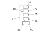
- the observation apparatus 3 that receives a set of screens C via the Internet 4 has the image receiving means 32, two displays 31l and 31r for displaying left and right eye images, and goggles.
- a screen selection means 34 for selecting a left-eye screen and a right-eye screen from a set of screens C; a screen cut-out means 35 for cutting out the left-eye and right-eye display screens D1 and Dr from the selected screen Bi, Bi ⁇ 1; Display means 36 for displaying the cut-out screen on a display;
- an omnidirectional or omnidirectional image corresponding to the direction of the observation device can be observed at a remote place without connecting the screens captured by a plurality of cameras that are responsible for capturing images in the respective directions.
- FIG. 1 Hardware configuration diagram Perspective view of camera unit Diagram showing image conversion on server
- Side view showing an example of a camera unit with variable lens spacing
- FIG. 1 is a camera unit
- 2 is a computer for image distribution (hereinafter referred to as “distribution server”)
- 3 is a computer for image distribution (hereinafter referred to as “distribution server”)
- 3 is a computer for image distribution (hereinafter referred to as “distribution server”)
- 3 is a computer for image distribution (hereinafter referred to as “distribution server”)
- 3 is a computer for image distribution (hereinafter referred to as “distribution server”)
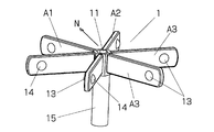
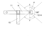
- Each camera Ai includes a plurality of lenses (two in the figure) 13 and 14 and shoots an omnidirectional image with the center point between the lenses as the imaging center.
- each camera Ai does not show itself, but the other camera arranged adjacently and the holder 11 holding the camera are shown.
- the plurality of cameras Ai are mounted on the holder 11 so that right-eye and left-eye omnidirectional images in which the adjacent cameras and holders are not captured can be obtained from a plurality of images in which the adjacent cameras and holders are captured. Yes.
- each camera Ai is mounted so that the optical axes of its lenses 13 and 14 are on the same plane, and those optical axes are directed to the sides of the regular polygon on the plane. .
- the holder 11 is positioned at the center of arrangement of the plurality of cameras Ai, and a plurality of holders 11 are supplemented with a captured image of another camera so that the direction in which the holder or the adjacent camera in the captured image of a certain camera is reflected.
- Cameras Ai are attached.
- the plurality of cameras Ai are synchronously controlled so as to perform shooting operations at the same timing, whether they are still images or moving images.
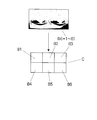
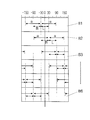
- the distribution server 2 receives n shooting screens Bi simultaneously shot by each of the n cameras Ai of the camera unit, and converts them into a set of screens C via the Internet 4. Deliver to 3 ... A plurality of cameras Ai are simultaneously provided with shooting signals. However, depending on the performance of the cameras, it may not be possible to perform shooting with exactly the same timing. In such a case, before the plurality of shooting screens Bi are set as a set of screens C, correction for correcting a shift in shooting timing is performed. For example, the image is corrected by calculating the displacement of the image at a timing shift from the shift between images taken at short time intervals.
- the goggle 3 is a direction detection means for detecting a change in the viewing direction, at least the viewing direction of the viewer wearing the goggles, such as the left and right displays 31l and 31r, a gyroscope and an angular accelerometer, and a level and a compass. 33 is provided.
- the goggles 3 further include a screen selection unit 34 for selecting a left-eye screen and a right-eye screen from the n shooting screens Bi in the set of screens C according to the direction detected by the direction detection unit 33, and the selected screen.
- screen cutout means 35 for cutting out the display screens D1 and Dr projected on the left-eye and right-eye displays, and display means 36 for displaying the cut-out screens on the respective displays 31l and 31r.
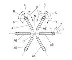
- the camera unit 1 is installed with the bisector direction N of the cameras A1 and A2 facing north as the reference direction, as shown in FIG. If the goggles 3 have a compass, it can detect its own direction from the reference direction, so that the cameras arranged on both sides of the facing direction are taken as right and left eye shooting screens Bi and Bi ⁇ 1.
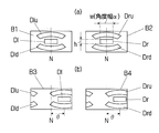
- the screen cutout means 35 cuts out the display screens Dl and Dr having the width w and the height h that are projected from the respective screens B1 and B2 on the left and right displays 31l and 31r.
- the screen selection means 34 when the observer turns on the goggles. Selects the shooting screen B1 of the camera A1 as the screen for the left eye and the shooting screen B2 of the camera A2 as the screen for the right eye from the received set of screens C.
- the screen cutout means 35 selects the screens B1 and B2 respectively. Cut out the display screens Dl and Dr having a width w and a height h projected on the left and right displays 31l and 31r.
- the center of the width of all the shooting screens B is set to the reference direction N of the camera unit, as shown in FIG. 7A, the display screen D1 for left eye and right eye that is cut out when the goggles are facing the reference direction. , Dr is cut out with the width center of each of the photographing screens B1 and B2 as the width center.
- the screen to be cut out is a simple rectangle or fan shape, but the display of goggles is not only a simple rectangle, and goggles usually have eyepieces and the image on the display is distorted. Therefore, the screens Dl and Dr to be cut out are cut out in shapes corresponding to the respective displays and eyepieces.
- the cut out display screens Dlu and Dru move upward, but the spherical surface is developed on a cylindrical surface.
- the screens cut out when the goggles are directed upward are the screens Dlu and Dru that expand in the horizontal direction as they are directed upward and are deformed into a fan shape with the upper side wider than the lower side.
- the screens Dld and Drd are transformed into a fan shape in which the lower side spreading in the horizontal direction is longer than the upper side.
- the display means 36 converts the screens Dl and Dr cut out from the equator into appropriate images according to the angle of view of the goggles and the eyepiece and displays them on the displays 31l and 31r.
- the screens Dlu and Dru or Dld and Drd cut out in a wide fan shape are converted into screens with the same aspect ratio as the display screens Dl and Dr on the equator. Displayed on each display.
- the centers of the display screens D1 and Dr cut out from the shooting screens B1 and B2 also move to the right according to the direction in which the goggles are directed. If the direction of the goggles changes only in the horizontal direction at the same height, the width w of the cut-out display screen is constant. In the case of six cameras, the left-eye display screen Dl and the right-eye display screens Dl and Dr are photographed screens B1 and B2 while the direction of the goggles is 30 degrees ( ⁇ 30 degrees) left and right from the reference direction. It is cut out with the direction of the goggles facing from the center of the width.
- the shooting screen is converted.
- the shooting screen B2 that has been used for the right eye so far is selected as the screen for the left eye, and the camera A2 is used as the screen for the right eye.
- the shooting screen B3 of the camera A3 on the right side is selected.
- the shooting screen B3 is selected for the left eye and the shooting screen B4 is selected for the right eye.
- the shooting screen B6 is selected for the left eye, the shooting screen B1 is selected for the right eye, and is further moved to 90 degrees in the left direction.
- the shooting screen B5 is selected for the left eye, and the shooting screen B6 is selected for the right eye.
- the center of the width of the display screens Dl and Dr to be cut out is the direction in which the goggles are facing, regardless of which shooting screen is selected. It is.
- a range of 60 degrees clockwise from the direction in which each camera Ai faces is a range L in which an image for the left eye is photographed as a pair with the camera on the right side, and a range of 60 degrees clockwise is the left side. Since the viewing angle of the width w of the display screen to be cut out is ⁇ , a range expanded by ⁇ / 2 outside these ranges (2 ⁇ 360 / n) ) + ⁇ is the shooting range of each camera Ai.
- each camera is an area on the equator.
- the angle width ⁇ cut out from the shooting screen as a display screen is widened, so the area to be handled is also widened. It is only necessary to determine the shape of the holder and the number of cameras so that the adjacent cameras and holders do not appear in the area of each camera.
- the viewing angle in the height direction of the goggles 3 is ⁇ , and 180 ° + ⁇ degrees in the height direction.
- the size and shape do not allow the holder 11 to enter the region (see FIG. 6).
- the image of the viewing angle ⁇ in the height direction provided in the goggles 3 can be displayed on the display without converting the shooting screen.
- the shooting screen selected at that time is changed.
- the camera to be used is not limited to a camera that can capture a complete omnidirectional or omnidirectional camera, but may be a omnidirectional or omnidirectional camera that is partially missing.
- a camera that can capture a complete omnidirectional or omnidirectional camera but may be a omnidirectional or omnidirectional camera that is partially missing.
- it is an omnidirectional camera that does not show a cone part with an apex angle of 60 degrees directly below, if the direction directly below is placed in the direction of the center of the holder and the direction is changed by the distribution server, this The omnidirectional binocular stereoscopic image of the invention can be provided.
- the holder 11 is attached to the support column 15 and the helmet, but the body of the person wearing the support column 15 and the helmet at this time is reflected in an image observed with goggles. Since these pillars and helmets naturally enter the field of view even when people observe on site, the images that they are reflected in are rather natural images. Normally, omnidirectional images and omnidirectional images are used. It will not be an obstacle to providing.
- Binocular stereoscopic images can be provided.
- the left and right eye photography screens are taken, and the left and right cameras in the direction in which the goggles are directed.
- the width w (lateral angle ⁇ ) corresponding to the viewing angle of the display provided in the goggles and the height h (height direction)
- each photographing screen Bi is an omnidirectional screen, and for example, it is possible to cut out a display screen that has moved 35 degrees to the right from the reference direction N from the photographing screen B1. Therefore, if switching is performed with a slight time delay with respect to the movement of the goggles, images are frequently switched due to slight movement or vibration of the goggles when the goggles are facing the direction of switching the shooting screen. Can be prevented. Further, at the time of this switching, the images can be switched smoothly by switching while fading in and fading out in a short time.
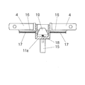
- the distance between the lenses of the cameras next to the cameras A is based on the distance between both eyes of the human, but depending on the shooting target and the specifications of the goggles, it may be natural to stereoscopically increase the distance slightly. May be visible. Considering this, it is conceivable to use a holder having a structure that can adjust the distance between the lenses of the adjacent camera as the holder 11.
- each camera is mounted on a support base 16 attached to a holder base 11a so as to be slidable in the radial direction, and these support bases are attached in a contracting direction (a direction moving inward in the radial direction).
- a spring 17 is provided, and the base end of the support 16 is brought into contact with a cone (conical member) 19 screwed into a screw 18 provided at the center of the holder.
- the present invention can also deliver an omnidirectional image, using an omnidirectional camera as a camera, It is also possible to provide a binocular stereoscopic image.
Landscapes
- Engineering & Computer Science (AREA)
- Multimedia (AREA)
- Signal Processing (AREA)
- Physics & Mathematics (AREA)
- General Physics & Mathematics (AREA)
- Testing, Inspecting, Measuring Of Stereoscopic Televisions And Televisions (AREA)
- Studio Devices (AREA)
- Stereoscopic And Panoramic Photography (AREA)
- Two-Way Televisions, Distribution Of Moving Picture Or The Like (AREA)
- Closed-Circuit Television Systems (AREA)
Abstract
Description
提供する画像が全方位画像のときは、高さ方向については、複数のカメラAi及びホルダ11をβ度の領域外に位置させれば良い。
2 サーバ
3 観察装置
4 インターネット
11 カメラホルダ
31l、31r ディスプレイ
32 受信手段
33 方向検出手段
34 画面選択手段
35 画面切り出し手段
36 表示手段
Ai(i=1~n) 全天球カメラ
Bi(i=1~n)撮影画面
C 一組の画像
Dl、Dr 表示画面
h 表示画面の高さ
w 表示画面の幅
α 横方向の視野角
β 高さ方向の視野角
Claims (9)
- 全方位ないし全方位かつ全高さにおける双眼立体視画像を提供する双眼立体視画像の提供方法であって、
隣接するカメラ相互のレンズ間間隔を略両眼の間隔とした正多角形の頂点位置に全方位ないし全天球カメラを配置し、
各カメラが撮影した同一タイミングの全方位ないし全天球画面を一組の画面として観察装置に提供し、
観察装置は、観察する方向を検出したときに、
提供された前記一組の画面から当該方向を挟む2個のカメラの撮影画面を左目用及び右目用の撮影画面として選択し、当該選択した撮影画面から前記方向を中心としかつ観察装置が備えるディスプレイの視野角に相当する幅及び高さを備えた表示画面を切り出して当該ディスプレイに表示する、双眼立体視画像の提供方法。 - 前記一組の画面を複数の観察装置にインターネットを介して提供する、請求項1記載の双眼立体視画像の提供方法。
- 双眼立体視画像が動画像である、請求項1又は2記載の双眼立体視画像の提供方法。
- 左目用と右目用の画像を表示するための2個のディスプレイと、方向検出手段と、複数のカメラが撮影した全方位ないし全天球画面を一組として受信する受信手段と、方向検出手段が検出した方向に応じて前記一組の画面から左目用と右目用の画面を選択する画面選択手段と、選択した画面から前記方向を幅中心とする左目用と右目用の表示画面を切り出す画面切り出し手段と、切り出した画面をそれぞれのディスプレイに表示する表示手段とを備えている、双眼立体視画像の観察装置。
- 前記受信手段がn個の全方位ないし全天球画面を一組として受信しているとき、前記画面選択手段は、前記方向検出手段の検出方向が現に選択している左目用と右目用の画面の中心の方向から360/2n度を超えたときに、選択する左目用と右目用の画面を変更する、請求項4記載の双眼立体視画像の観察装置。
- 前記画面選択手段は、前記方向検出手段の検出方向が現に選択している左目用と右目用の画面の中心の方向から右方向に360/2n度を超えたときに、現に選択している右目用の画面を左目用の画面として選択し、左方向に360/2n度を超えたときに、現に選択している左目用の画面を右目用の画面として選択する、請求項5記載の双眼立体視画像の観察装置。
- 切り出し手段が、前記選択された撮影画面から方向検出手段が検出した高さ方向に応じた扇形の画面を切り出し、表示手段が、当該扇形の画面を高さ0における形状の画面に変換して表示する、請求項4、5又は6記載の双眼立体視画像の観察装置。
- 観察者に対する横方向の視野角がα、高さ方向の視野角がβのディスプレイを備えた請求項4記載の観察装置に提供する画像を撮影するカメラユニットであって、角数がnの正多角形の頂点位置に配置されたn個の全方位カメラを保持するホルダを備え、当該ホルダ及び各カメラは、前記正n角形の中心から各カメラの撮影中心Pを通る放射方向を中心とする横方向に(2×360/n)+α度の領域外及び高さ方向にβ度の領域外に配置されている、全方位双眼立体視画像を提供するためのカメラユニット。
- 観察者に対する横方向の視野角がα、高さ方向の視野角がβのディスプレイを備えた請求項4記載の観察装置に提供する画像を撮影するカメラユニットであって、角数がnの正多角形の頂点位置に配置されたn個の全天球カメラを保持するホルダを備え、当該ホルダ及び各カメラは、前記正n角形の中心から各カメラの撮影中心Pを通る放射方向を中心とする横方向に(2×360/n)+α度の領域外及び高さ方向に180+β度の領域外に配置されている、全天球双眼立体視画像を提供するためのカメラユニット。
Priority Applications (4)
| Application Number | Priority Date | Filing Date | Title |
|---|---|---|---|
| CN201680033762.9A CN107646193B (zh) | 2015-06-22 | 2016-06-20 | 双目立体视觉图像的提供方法、传送装置和照相机单元 |
| US15/735,988 US20180184067A1 (en) | 2015-06-22 | 2016-06-20 | Providing method of binocular stereoscopic image, delivering device and camera unit |
| EP16814309.7A EP3313071A4 (en) | 2015-06-22 | 2016-06-20 | METHOD FOR PROVIDING A BINOCULAR STEREOSCOPIC IMAGE, OBSERVATION DEVICE AND CAMERA UNIT |
| JP2017524895A JP6845506B2 (ja) | 2015-06-22 | 2016-06-20 | 双眼立体視画像の提供方法、配信装置及びカメラユニット |
Applications Claiming Priority (2)
| Application Number | Priority Date | Filing Date | Title |
|---|---|---|---|
| JP2015124978 | 2015-06-22 | ||
| JP2015-124978 | 2015-06-22 |
Publications (1)
| Publication Number | Publication Date |
|---|---|
| WO2016208539A1 true WO2016208539A1 (ja) | 2016-12-29 |
Family
ID=57585719
Family Applications (1)
| Application Number | Title | Priority Date | Filing Date |
|---|---|---|---|
| PCT/JP2016/068272 Ceased WO2016208539A1 (ja) | 2015-06-22 | 2016-06-20 | 双眼立体視画像の提供方法、観察装置及びカメラユニット |
Country Status (5)
| Country | Link |
|---|---|
| US (1) | US20180184067A1 (ja) |
| EP (1) | EP3313071A4 (ja) |
| JP (1) | JP6845506B2 (ja) |
| CN (1) | CN107646193B (ja) |
| WO (1) | WO2016208539A1 (ja) |
Cited By (5)
| Publication number | Priority date | Publication date | Assignee | Title |
|---|---|---|---|---|
| WO2019155934A1 (ja) * | 2018-02-09 | 2019-08-15 | ソニー株式会社 | 画像処理装置、画像処理方法および画像処理プログラム |
| JP2024546082A (ja) * | 2021-12-03 | 2024-12-17 | アップル インコーポレイテッド | メディアをキャプチャ及び表示するためのデバイス、方法、及びグラフィカルユーザインタフェース |
| US12394077B2 (en) | 2018-09-28 | 2025-08-19 | Apple Inc. | Displaying and editing images with depth information |
| US12530116B2 (en) | 2018-02-09 | 2026-01-20 | Apple Inc. | Media capture lock affordance for graphical user interface |
| US12602154B2 (en) | 2024-01-18 | 2026-04-14 | Apple Inc. | User interfaces integrating hardware buttons |
Families Citing this family (1)
| Publication number | Priority date | Publication date | Assignee | Title |
|---|---|---|---|---|
| WO2020104989A1 (en) * | 2018-11-22 | 2020-05-28 | Slovenská Technická Univerzita V Bratislave | Arrangement of multiple cameras in a multi-directional stereo camera system |
Citations (3)
| Publication number | Priority date | Publication date | Assignee | Title |
|---|---|---|---|---|
| JPH08191419A (ja) * | 1995-01-10 | 1996-07-23 | Yamaha Corp | 頭部装着型表示システム |
| JP2013033321A (ja) * | 2011-08-01 | 2013-02-14 | Dainippon Printing Co Ltd | 動画提示装置 |
| JP2014131154A (ja) * | 2012-12-28 | 2014-07-10 | Pioneer Electronic Corp | 映像処理装置、映像受信装置、映像送信装置及び映像処理方法 |
Family Cites Families (4)
| Publication number | Priority date | Publication date | Assignee | Title |
|---|---|---|---|---|
| US7224382B2 (en) * | 2002-04-12 | 2007-05-29 | Image Masters, Inc. | Immersive imaging system |
| US8004558B2 (en) * | 2005-04-07 | 2011-08-23 | Axis Engineering Technologies, Inc. | Stereoscopic wide field of view imaging system |
| JP5020398B1 (ja) * | 2011-06-29 | 2012-09-05 | パナソニック株式会社 | 画像変換装置、カメラ、画像変換方法およびプログラム |
| JP6126820B2 (ja) * | 2012-11-09 | 2017-05-10 | 任天堂株式会社 | 画像生成方法、画像表示方法、画像生成プログラム、画像生成システム、および画像表示装置 |
-
2016
- 2016-06-20 US US15/735,988 patent/US20180184067A1/en not_active Abandoned
- 2016-06-20 JP JP2017524895A patent/JP6845506B2/ja active Active
- 2016-06-20 EP EP16814309.7A patent/EP3313071A4/en not_active Withdrawn
- 2016-06-20 CN CN201680033762.9A patent/CN107646193B/zh not_active Expired - Fee Related
- 2016-06-20 WO PCT/JP2016/068272 patent/WO2016208539A1/ja not_active Ceased
Patent Citations (3)
| Publication number | Priority date | Publication date | Assignee | Title |
|---|---|---|---|---|
| JPH08191419A (ja) * | 1995-01-10 | 1996-07-23 | Yamaha Corp | 頭部装着型表示システム |
| JP2013033321A (ja) * | 2011-08-01 | 2013-02-14 | Dainippon Printing Co Ltd | 動画提示装置 |
| JP2014131154A (ja) * | 2012-12-28 | 2014-07-10 | Pioneer Electronic Corp | 映像処理装置、映像受信装置、映像送信装置及び映像処理方法 |
Non-Patent Citations (1)
| Title |
|---|
| See also references of EP3313071A4 * |
Cited By (8)
| Publication number | Priority date | Publication date | Assignee | Title |
|---|---|---|---|---|
| WO2019155934A1 (ja) * | 2018-02-09 | 2019-08-15 | ソニー株式会社 | 画像処理装置、画像処理方法および画像処理プログラム |
| JPWO2019155934A1 (ja) * | 2018-02-09 | 2021-01-28 | ソニー株式会社 | 画像処理装置、画像処理方法および画像処理プログラム |
| US12530116B2 (en) | 2018-02-09 | 2026-01-20 | Apple Inc. | Media capture lock affordance for graphical user interface |
| US12394077B2 (en) | 2018-09-28 | 2025-08-19 | Apple Inc. | Displaying and editing images with depth information |
| JP2024546082A (ja) * | 2021-12-03 | 2024-12-17 | アップル インコーポレイテッド | メディアをキャプチャ及び表示するためのデバイス、方法、及びグラフィカルユーザインタフェース |
| JP7713597B2 (ja) | 2021-12-03 | 2025-07-25 | アップル インコーポレイテッド | メディアをキャプチャ及び表示するためのデバイス、方法、及びグラフィカルユーザインタフェース |
| US12506953B2 (en) | 2021-12-03 | 2025-12-23 | Apple Inc. | Device, methods, and graphical user interfaces for capturing and displaying media |
| US12602154B2 (en) | 2024-01-18 | 2026-04-14 | Apple Inc. | User interfaces integrating hardware buttons |
Also Published As
| Publication number | Publication date |
|---|---|
| CN107646193A (zh) | 2018-01-30 |
| US20180184067A1 (en) | 2018-06-28 |
| EP3313071A1 (en) | 2018-04-25 |
| CN107646193B (zh) | 2020-01-21 |
| EP3313071A4 (en) | 2019-01-23 |
| JPWO2016208539A1 (ja) | 2018-05-24 |
| JP6845506B2 (ja) | 2021-03-24 |
Similar Documents
| Publication | Publication Date | Title |
|---|---|---|
| JP6845506B2 (ja) | 双眼立体視画像の提供方法、配信装置及びカメラユニット | |
| CN107111928B (zh) | 远程控制作业机用显示系统 | |
| US20170269367A1 (en) | Microlens array-based near-eye display (ned) | |
| US11184597B2 (en) | Information processing device, image generation method, and head-mounted display | |
| EP2569951B1 (en) | System and method for multi-viewpoint video capture | |
| CN108093244B (zh) | 一种远程随动立体视觉系统 | |
| WO2002044808A3 (en) | System and method for spherical stereoscopic photographing | |
| ES2824049T3 (es) | Sistema y método para la monitorización remota de al menos un área de observación | |
| CN101285935A (zh) | 用于图像显示器的防晕装置 | |
| JP2018110295A5 (ja) | ||
| US9479761B2 (en) | Document camera, method for controlling document camera, program, and display processing system | |
| US20130021448A1 (en) | Stereoscopic three-dimensional camera rigs | |
| CN107431799B (zh) | 单眼立体相机 | |
| JP5223096B2 (ja) | 3d映像撮影制御システム、3d映像撮影制御方法、およびプログラム | |
| JP2021048459A (ja) | 画像処理装置、画像処理方法、及びプログラム | |
| CN103235478A (zh) | 用于环幕立体摄像的系统、设备、图像处理方法及装置 | |
| JP4183466B2 (ja) | 全方位双眼立体視画像の生成方法 | |
| CN202995248U (zh) | 一种用于环幕立体摄像的设备及系统 | |
| JP2012199759A (ja) | 情報処理装置、そのプログラム、および情報処理方法 | |
| JP2013105000A (ja) | 映像表示装置及び映像表示方法 | |
| JP2011182003A (ja) | パノラマカメラ及び360度パノラマ立体映像システム | |
| KR20170059879A (ko) | 입체 영상 촬영 장치 | |
| JPH0980353A (ja) | 立体映像観察装置 | |
| JPH03119890A (ja) | 立体視視覚装置 | |
| KR101549874B1 (ko) | 입체 동영상 촬영용 카메라 및 이의 사용방법 |
Legal Events
| Date | Code | Title | Description |
|---|---|---|---|
| 121 | Ep: the epo has been informed by wipo that ep was designated in this application |
Ref document number: 16814309 Country of ref document: EP Kind code of ref document: A1 |
|
| DPE1 | Request for preliminary examination filed after expiration of 19th month from priority date (pct application filed from 20040101) | ||
| WWE | Wipo information: entry into national phase |
Ref document number: 15735988 Country of ref document: US |
|
| ENP | Entry into the national phase |
Ref document number: 2017524895 Country of ref document: JP Kind code of ref document: A |
|
| NENP | Non-entry into the national phase |
Ref country code: DE |
|
| WWE | Wipo information: entry into national phase |
Ref document number: 2016814309 Country of ref document: EP |