WO2016208628A1 - Appareil d'éclairage - Google Patents
Appareil d'éclairage Download PDFInfo
- Publication number
- WO2016208628A1 WO2016208628A1 PCT/JP2016/068527 JP2016068527W WO2016208628A1 WO 2016208628 A1 WO2016208628 A1 WO 2016208628A1 JP 2016068527 W JP2016068527 W JP 2016068527W WO 2016208628 A1 WO2016208628 A1 WO 2016208628A1
- Authority
- WO
- WIPO (PCT)
- Prior art keywords
- light
- optical system
- light source
- lens
- diffusing
- Prior art date
- Legal status (The legal status is an assumption and is not a legal conclusion. Google has not performed a legal analysis and makes no representation as to the accuracy of the status listed.)
- Ceased
Links
Images








Classifications
-
- F—MECHANICAL ENGINEERING; LIGHTING; HEATING; WEAPONS; BLASTING
- F21—LIGHTING
- F21S—NON-PORTABLE LIGHTING DEVICES; SYSTEMS THEREOF; VEHICLE LIGHTING DEVICES SPECIALLY ADAPTED FOR VEHICLE EXTERIORS
- F21S41/00—Illuminating devices specially adapted for vehicle exteriors, e.g. headlamps
- F21S41/10—Illuminating devices specially adapted for vehicle exteriors, e.g. headlamps characterised by the light source
- F21S41/14—Illuminating devices specially adapted for vehicle exteriors, e.g. headlamps characterised by the light source characterised by the type of light source
- F21S41/16—Laser light sources
-
- F—MECHANICAL ENGINEERING; LIGHTING; HEATING; WEAPONS; BLASTING
- F21—LIGHTING
- F21K—NON-ELECTRIC LIGHT SOURCES USING LUMINESCENCE; LIGHT SOURCES USING ELECTROCHEMILUMINESCENCE; LIGHT SOURCES USING CHARGES OF COMBUSTIBLE MATERIAL; LIGHT SOURCES USING SEMICONDUCTOR DEVICES AS LIGHT-GENERATING ELEMENTS; LIGHT SOURCES NOT OTHERWISE PROVIDED FOR
- F21K9/00—Light sources using semiconductor devices as light-generating elements, e.g. using light-emitting diodes [LED] or lasers
- F21K9/20—Light sources comprising attachment means
- F21K9/23—Retrofit light sources for lighting devices with a single fitting for each light source, e.g. for substitution of incandescent lamps with bayonet or threaded fittings
- F21K9/233—Retrofit light sources for lighting devices with a single fitting for each light source, e.g. for substitution of incandescent lamps with bayonet or threaded fittings specially adapted for generating a spot light distribution, e.g. for substitution of reflector lamps
-
- F—MECHANICAL ENGINEERING; LIGHTING; HEATING; WEAPONS; BLASTING
- F21—LIGHTING
- F21K—NON-ELECTRIC LIGHT SOURCES USING LUMINESCENCE; LIGHT SOURCES USING ELECTROCHEMILUMINESCENCE; LIGHT SOURCES USING CHARGES OF COMBUSTIBLE MATERIAL; LIGHT SOURCES USING SEMICONDUCTOR DEVICES AS LIGHT-GENERATING ELEMENTS; LIGHT SOURCES NOT OTHERWISE PROVIDED FOR
- F21K9/00—Light sources using semiconductor devices as light-generating elements, e.g. using light-emitting diodes [LED] or lasers
- F21K9/60—Optical arrangements integrated in the light source, e.g. for improving the colour rendering index or the light extraction
-
- F—MECHANICAL ENGINEERING; LIGHTING; HEATING; WEAPONS; BLASTING
- F21—LIGHTING
- F21S—NON-PORTABLE LIGHTING DEVICES; SYSTEMS THEREOF; VEHICLE LIGHTING DEVICES SPECIALLY ADAPTED FOR VEHICLE EXTERIORS
- F21S41/00—Illuminating devices specially adapted for vehicle exteriors, e.g. headlamps
- F21S41/10—Illuminating devices specially adapted for vehicle exteriors, e.g. headlamps characterised by the light source
- F21S41/14—Illuminating devices specially adapted for vehicle exteriors, e.g. headlamps characterised by the light source characterised by the type of light source
- F21S41/176—Light sources where the light is generated by photoluminescent material spaced from a primary light generating element
-
- F—MECHANICAL ENGINEERING; LIGHTING; HEATING; WEAPONS; BLASTING
- F21—LIGHTING
- F21V—FUNCTIONAL FEATURES OR DETAILS OF LIGHTING DEVICES OR SYSTEMS THEREOF; STRUCTURAL COMBINATIONS OF LIGHTING DEVICES WITH OTHER ARTICLES, NOT OTHERWISE PROVIDED FOR
- F21V5/00—Refractors for light sources
- F21V5/02—Refractors for light sources of prismatic shape
-
- F—MECHANICAL ENGINEERING; LIGHTING; HEATING; WEAPONS; BLASTING
- F21—LIGHTING
- F21V—FUNCTIONAL FEATURES OR DETAILS OF LIGHTING DEVICES OR SYSTEMS THEREOF; STRUCTURAL COMBINATIONS OF LIGHTING DEVICES WITH OTHER ARTICLES, NOT OTHERWISE PROVIDED FOR
- F21V5/00—Refractors for light sources
- F21V5/04—Refractors for light sources of lens shape
-
- G—PHYSICS
- G02—OPTICS
- G02B—OPTICAL ELEMENTS, SYSTEMS OR APPARATUS
- G02B26/00—Optical devices or arrangements for the control of light using movable or deformable optical elements
- G02B26/08—Optical devices or arrangements for the control of light using movable or deformable optical elements for controlling the direction of light
- G02B26/10—Scanning systems
- G02B26/12—Scanning systems using multifaceted mirrors
-
- G—PHYSICS
- G02—OPTICS
- G02B—OPTICAL ELEMENTS, SYSTEMS OR APPARATUS
- G02B27/00—Optical systems or apparatus not provided for by any of the groups G02B1/00 - G02B26/00, G02B30/00
- G02B27/48—Laser speckle optics
-
- G—PHYSICS
- G03—PHOTOGRAPHY; CINEMATOGRAPHY; ANALOGOUS TECHNIQUES USING WAVES OTHER THAN OPTICAL WAVES; ELECTROGRAPHY; HOLOGRAPHY
- G03H—HOLOGRAPHIC PROCESSES OR APPARATUS
- G03H1/00—Holographic processes or apparatus using light, infrared or ultraviolet waves for obtaining holograms or for obtaining an image from them; Details peculiar thereto
- G03H1/22—Processes or apparatus for obtaining an optical image from holograms
- G03H1/2286—Particular reconstruction light ; Beam properties
-
- G—PHYSICS
- G03—PHOTOGRAPHY; CINEMATOGRAPHY; ANALOGOUS TECHNIQUES USING WAVES OTHER THAN OPTICAL WAVES; ELECTROGRAPHY; HOLOGRAPHY
- G03H—HOLOGRAPHIC PROCESSES OR APPARATUS
- G03H1/00—Holographic processes or apparatus using light, infrared or ultraviolet waves for obtaining holograms or for obtaining an image from them; Details peculiar thereto
- G03H1/22—Processes or apparatus for obtaining an optical image from holograms
- G03H1/2202—Reconstruction geometries or arrangements
- G03H1/2205—Reconstruction geometries or arrangements using downstream optical component
- G03H2001/2213—Diffusing screen revealing the real holobject, e.g. container filed with gel to reveal the 3D holobject
- G03H2001/2215—Plane screen
- G03H2001/2218—Plane screen being perpendicular to optical axis
-
- G—PHYSICS
- G03—PHOTOGRAPHY; CINEMATOGRAPHY; ANALOGOUS TECHNIQUES USING WAVES OTHER THAN OPTICAL WAVES; ELECTROGRAPHY; HOLOGRAPHY
- G03H—HOLOGRAPHIC PROCESSES OR APPARATUS
- G03H1/00—Holographic processes or apparatus using light, infrared or ultraviolet waves for obtaining holograms or for obtaining an image from them; Details peculiar thereto
- G03H1/22—Processes or apparatus for obtaining an optical image from holograms
- G03H1/2202—Reconstruction geometries or arrangements
- G03H2001/2223—Particular relationship between light source, hologram and observer
-
- G—PHYSICS
- G03—PHOTOGRAPHY; CINEMATOGRAPHY; ANALOGOUS TECHNIQUES USING WAVES OTHER THAN OPTICAL WAVES; ELECTROGRAPHY; HOLOGRAPHY
- G03H—HOLOGRAPHIC PROCESSES OR APPARATUS
- G03H1/00—Holographic processes or apparatus using light, infrared or ultraviolet waves for obtaining holograms or for obtaining an image from them; Details peculiar thereto
- G03H1/22—Processes or apparatus for obtaining an optical image from holograms
- G03H1/2286—Particular reconstruction light ; Beam properties
- G03H2001/2292—Using scanning means
Definitions
- the present disclosure relates to an illumination device that illuminates a predetermined range using light.
- illumination devices using a coherent light source are widely used.
- a laser light source that oscillates laser light is used as the coherent light source.
- JP2012-146621A discloses a vehicular lamp.
- This vehicular lamp has a light source that can be constituted by a laser oscillation device, and four hologram elements. Each hologram element is arranged at a position where the laser light from the light source can be received by the rotation driving device. Each hologram element diffracts the laser light and realizes illumination with a predetermined light distribution pattern. By appropriately selecting a hologram element that is irradiated with laser light, illumination with a desired light distribution pattern can be realized.
- it is necessary to regulate the irradiation of laser light while changing the positions of the four hologram elements from the viewpoint of preventing illumination light from being irradiated to an unintended region. In this case, the period during which the light source stops emitting light becomes longer. Therefore, it is not possible to illuminate the illuminated area with a sufficiently bright light quantity by fully utilizing the performance of the light source.
- the present disclosure has been made in consideration of the above points, and provides an illuminating device that can fully illuminate an illuminated area with a desired light distribution pattern by fully utilizing the performance of a coherent light source. This is the first purpose.
- a second object is to provide a lighting device that can be used.
- the lighting device includes: A light diffusing element having a plurality of element diffusing elements for diffusing incident light; A coherent light source that emits coherent light; A shaping optical system for shaping the coherent light; A scanning device that adjusts the traveling direction of the coherent light and thereby scans the coherent light on the light diffusing element; A condensing optical system provided in the optical path of the coherent light from the shaping optical system to the light diffusing element, The condensing optical system condenses the coherent light so that a spot area on the light diffusing element is smaller than the element diffusing element, Each element diffusing element diffuses the incident coherent light, and thereby illuminates the element illuminated area corresponding to the element diffusing element.
- the shaping optical system divides coherent light emitted from the coherent light source into a plurality of light beams
- the condensing optical system may adjust the optical paths of the plurality of light beams so that each of the plurality of light beams overlaps at least partially on the light diffusing element.
- the condensing optical system may include a lens, and the light diffusing element may be disposed at a focal position of the lens.
- the shaping optical system includes a collimating lens and a lens array provided in an optical path from the collimating lens to the condensing optical system. Also good.
- the lens array includes a plurality of element lenses;
- the light beams emitted from the plurality of element lenses may have the same light distribution.
- the shaping optical system may be a beam homogenizer.
- the illumination device may further include a light emission control unit that controls emission of the coherent light from the coherent light source.
- the light emission control unit controls light emission of the coherent light of the coherent light source according to an irradiation position of the coherent light on the light diffusing element. May be.
- the light diffusing element is a hologram recording medium;
- the plurality of element diffusion elements may be element holograms in which different interference fringe patterns are formed.
- the light diffusing element is a lens array group having a plurality of lens arrays
- the plurality of element diffusion elements may include the lens array.
- the first embodiment of the present disclosure it is possible to brightly illuminate the illuminated area with a desired light distribution pattern by fully utilizing the performance of the coherent light source.
- the lighting device includes: An optical deflection element having a plurality of element deflection elements for adjusting the traveling direction of incident light; A light source; A diffusion optical system for diffusing the light source light emitted from the light source; A scanning device that adjusts the traveling direction of the light source light and thereby scans the light source light on the light deflection element; A condensing optical system provided in an optical path of the light source light from the diffusion optical system to the light deflection element, The condensing optical system condenses the light source light so that a spot area on the light deflection element is smaller than the element deflection element, Each element deflection element adjusts the traveling direction of the incident light source light, and thereby illuminates the element illuminated area corresponding to the element deflection element.
- the diffusion optical system divides the light source light into a plurality of light beams
- the condensing optical system may adjust optical paths of the plurality of light beams so that the plurality of light beams overlap at least partially on the light deflection element.
- the condensing optical system may include a lens, and the light deflection element may be disposed at a focal position of the lens.
- the diffusion optical system includes a collimating lens and a lens array provided in an optical path from the collimating lens to the condensing optical system. Also good.
- the lens array includes a plurality of element lenses;
- the light beams emitted from the plurality of element lenses may have the same light distribution.
- the diffusion optical system may be a beam homogenizer.
- the illumination device may further include a light emission control unit that controls emission of light from the light source.
- the light emission control unit may control emission of light from the light source according to an irradiation position of the light source light on the light deflection element. Good.
- the light deflection element is a diffraction grating array; Each element deflection element may be a diffraction grating.
- the light deflection element is a prism array; Each element deflection element may be a prism.
- the second embodiment of the present disclosure it is possible to brightly illuminate the illuminated area with a desired light distribution pattern by fully utilizing the performance of the light source.
- FIG. 1 is a diagram for explaining the first embodiment of the present disclosure, and is a perspective view schematically showing the overall configuration of the illumination device.
- FIG. 2 is a plan view showing the illumination device of FIG.
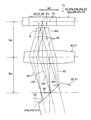
- FIG. 3 is a plan view showing the scanning device, the condensing optical system, and the light diffusing element of the illuminating device in FIG. 1, and is a diagram mainly for explaining the function of the condensing optical system.
- FIG. 4 is a diagram showing the light diffusing element and the illuminated area illuminated by the diffused light from the light diffusing element in the illuminating device of FIG. 1, and is a diagram for explaining the function of the light diffusing element.
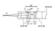
- FIG. 5 is a plan view showing a spot region on the light diffusing element.
- FIG. 6 is a plan view showing a spot region on the light diffusing element when the shaping optical system and the condensing optical system are omitted.
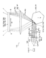
- FIG. 7 is a diagram for explaining the second embodiment of the present disclosure, and is a perspective view schematically showing the overall configuration of the illumination device.
- FIG. 8 is a plan view showing the illumination device of FIG.
- FIG. 9 is a plan view showing the scanning device, the condensing optical system, and the light deflecting element of the illumination device of FIG. 7, and is a diagram mainly for explaining the function of the condensing optical system.
- FIG. 10 is a plan view showing a light deflection element in the illumination device of FIG. FIG.
- FIG. 11 is a diagram showing the light deflection element and the illuminated area illuminated by the light from the light deflection element in the illumination device of FIG.
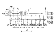
- FIG. 12 is a plan view showing a spot area on the optical deflection element.
- FIG. 13 is a plan view showing a spot region on the optical deflection element when the diffusion optical system and the condensing optical system are omitted.
- FIG. 1 is a perspective view schematically showing the overall configuration of the lighting device 10.
- the illuminating device 10 illuminates the illuminated area Z using coherent light.
- the illumination device 10 has a laser light source 15 that functions as a coherent light source.
- the laser light source 15 oscillates laser light as an example of coherent light.
- the illuminating device 10 includes a shaping optical system 20 that acts on light emitted from the laser light source 15, a scanning device 30, a condensing optical system 40, and a light diffusing element 50.
- the shaping optical system 20, the scanning device 30, the condensing optical system 40, and the light diffusing element 50 are arranged in this order along the optical path of the laser light from the laser light source 15. Acts on the laser beam.
- the illumination device 10 described here has a desired light distribution pattern while fully utilizing the performance of the coherent light source by the optical action of the shaping optical system 20 and the condensing optical system 40.
- the illuminated area Z can be illuminated with a high amount of light.
- each component will be described in order.
- the laser light source 15 has a plurality of light source sections 17 that emit laser light.
- the plurality of light source units 17 may be provided independently, or may be a light source module in which a plurality of light source units 17 are arranged side by side on a common substrate.
- the plurality of light source units 17 include a first light source unit 17a that oscillates light in a red emission wavelength region, a second light source unit 17b that oscillates light in a green emission wavelength region, and a blue light emission wavelength region.
- a third light source unit 17c that oscillates light. According to this example, it is possible to generate illumination lights of various colors including white illumination light by superimposing the three laser beams emitted from the plurality of light source units 17a, 17b, and 17c.
- the laser light source 15 may include two light source units 17 or four or more light source units 17 having different emission wavelength ranges. In order to increase the emission intensity, a plurality of light source units 17 may be provided for each emission wavelength region.
- the illumination device 10 includes a light emission control unit 12 connected to a laser light source 15.
- the light emission control unit 12 controls the light emission timing of the laser light from the laser light source 15.
- the light emission control unit 12 can switch the emission of the laser light from each of the light source units 17a, 17b, and 17c and the emission stop of the laser light independently from the other light source units.
- the control of whether or not the laser light is emitted by the light emission control unit 12 is performed based on the scanning timing of the plurality of laser lights by the scanning device 30, in other words, based on the incident position of the laser light on the light diffusion element 50.
- the laser light source 15 can emit three laser beams of red, blue and green, by controlling the emission timing of each laser beam, two or more colors of red, blue and green can be mixed. It is possible to generate illumination light of a combined color.
- the light emission control unit 12 may control whether to emit laser light from each light source unit 17, that is, control on / off of light emission, or block the optical path of the laser light emitted from each light source unit 17. Or not. In the latter case, an optical shutter unit (not shown) may be provided between each light source unit 17 and the shaping optical system 20, and the passage and blocking of the laser light may be switched by this optical shutter unit.
- the shaping optical system 20 shapes the laser light emitted from the laser light source 15. In other words, the shaping optical system 20 shapes the shape of the cross section perpendicular to the optical axis of the laser light and the three-dimensional shape of the laser light beam.
- FIG. 2 is a plan view showing the illumination device 10.
- the shaping optical system 20 includes a beam expander 21, a collimating lens 22, and a lens array 23 in the order along the optical path of the laser light.
- the beam expander 21 shapes the laser light emitted from the laser light source 15 into a divergent light beam.
- the collimating lens 22 reshapes the divergent light beam generated by the beam expander 21 into a parallel light beam lf1.
- the lens array 23 includes a plurality of element lenses 24 arranged at positions facing the collimating lens 22. Each element lens 24 is arranged such that its optical axis d 24 is parallel to the optical axis d 22 of the collimating lens 22.
- the plurality of element lenses 24 are arranged on a virtual plane vl orthogonal to the optical axis d 22 of the collimating lens 22.
- Each element lens 24 shapes the parallel light beam lf1 incident after being shaped by the collimator lens 22 into a convergent light beam lf2.
- the shaping optical system 20 divides the laser light emitted from the laser light source 15 into a plurality of light beams lf2.
- the shaping optical system 20 divides the light beam lf2 into the same number as the number of element lenses 24 included in the lens array 23.
- each element lens 24 shapes the parallel light beam lf1 incident after being shaped by the collimator lens 22 into a convergent light beam lf2. That is, each light beam lf2 divided by the shaping optical system 20 is a convergent light beam.
- the plurality of element lenses 24 are configured identically. Therefore, the plurality of light beams lf2 emitted from the plurality of element lenses 24 have the same light distribution.
- the plurality of light beams lf2 have the same convergence angle and convergence position, and the optical axes d lf2 of the plurality of light beams lf2 are parallel to each other.
- a plurality of shaping optical systems 20 may be provided corresponding to each light source unit 17 included in the laser light source 15.
- a single shaping optical system 20 that can adjust the optical path of the laser light from the plurality of light source units 17a, 17b, and 17c may be provided.
- a plurality of light source sections 17a, 17b, and 17c are arranged in the depth direction of the paper surface of FIG. 2, and the beam expander 21 diverges laser light only within the paper surface of FIG.
- the collimating lens 22 of the shaping optical system 20 and the element lens 24 of the lens array 23 may each be configured as a cylindrical lens extending in a certain cross-sectional shape in the depth direction of the paper surface of FIG. According to this example, the collimating lens 22 and the lens array 23 can be shared among the plurality of light source units 17.
- the scanning device 30 adjusts the traveling direction of the laser light emitted from the laser light source 15.
- the scanning device 30 changes the traveling direction of the laser light with time.
- the laser light emitted from the laser light source 15 scans the light diffusing element 50 by adjusting the optical path in the scanning device 30.
- the scanning device 30 is formed as a polygon mirror 31 having six reflecting surfaces.
- the polygon mirror 31 can periodically change the reflection direction of light incident from a certain direction by rotating the central axis about the rotation axis ra.
- Each of the six reflecting surfaces of the polygon mirror 31 is formed as a flat surface. Therefore, as shown in FIG.
- FIG. 3 is a partially enlarged plan view showing an optical path from the scanning device 30 to the light diffusing element 50.
- a plurality of light source units 17a, 17b, and 17c are arranged in a direction parallel to the rotation axis ra of the polygon mirror 31 (see FIG. 1).
- the reflecting surface of the polygon mirror 31 includes a first reflecting portion 31a, a second reflecting portion 31b, and a third reflecting portion 31c along the rotation axis ra.
- the first reflecting unit 31a reflects the laser beam emitted from the first light source unit 17a, and periodically changes the traveling direction of the laser beam in a plane orthogonal to the rotation axis ra.
- the second reflecting portion 31b reflects the laser light emitted from the second light source portion 17b, and the third reflecting portion 31c reflects the laser light emitted from the third light source portion 17c.
- the polygon mirror 31 reflects the light from the shaping optical system 20 at the focal position of the element lens 24 of the lens array 23 or a position near the focal position. It is positioned. Therefore, as shown in FIG. 3, the light reflected from the polygon mirror 31 generally becomes a divergent light beam lf ⁇ b> 3 having a reflection surface of the polygon mirror 31 as a divergence point.
- the scanning device 30 is not limited to the illustrated polygon mirror 31.
- a device that three-dimensionally changes the traveling direction of light incident from a certain direction can be used.
- a micro electromechanical system (MEMS) such as a digital mirror device (DMD) can be used as the scanning device 30.
- MEMS micro electromechanical system
- DMD digital mirror device
- the condensing optical system 40 is disposed in the optical path of laser light from the shaping optical system 20 to the light diffusing element 50.
- the condensing optical system 40 exerts an optical action on the laser light shaped by the shaping optical system 20.
- the condensing optical system 40 condenses the laser light to reduce the area of the spot region S on the light diffusing element 50, that is, the region irradiated with the laser light on the light diffusing element 50 at a certain moment. .
- the condensing optical system 40 is formed by a condensing lens 41 having a focal point Pf.
- the condensing lens 41 is disposed in the optical path of the laser light from the scanning device 30 toward the light diffusing element 50.
- the shaping optical system 20 divides the laser light into the plurality of light beams lf3.
- the optical axes d lf3 of the plurality of light beams lf3 are parallel to each other. Therefore, as shown in FIG.
- the optical axis d lf4 of the three light beams lf 4 is along the optical axis d 40 of the condenser lens 41 and the focal length f of the condenser lens 41.
- 40 intersects at a position Px on the virtual plane vlf separated from the condenser lens 41 by 40 .
- light diffuser 50 is disposed on a virtual plane vlf that along the optical axis d 40 of the condenser lens 41 spaced from the focal length f 40 only the condenser lens 41 of the condenser lens 41.
- the three light beams lf ⁇ b> 3 shaped by the shaping optical system 20 are combined and overlapped on the light diffusing element 50 at least partially by the light collecting action of the light collecting optical system 40.
- the polygon mirror 31 is positioned away from the condenser lens 41 by the focal length f 40 of the condenser lens 41 along the optical axis d 40 of the condenser lens 41 or In the vicinity of the position, the scanning device 30 and the condensing optical system 40 are arranged so as to reflect the laser light from the shaping optical system 20. Further, as described above, each of the plurality of light beams lf3 reflected by the polygon mirror 31 and incident on the condensing optical system 40 is a divergent light beam lf3, and the divergence point of the divergent light beam is a reflection surface of the polygon mirror 31. Located at or near the top.
- each light beam lf3 is converted into a parallel light beam lf4 by passing through the condenser lens 41.
- the plurality of light beams lf4 shaped by the shaping optical system 20 are irradiated to the same region on the light diffusing element 50 by the condensing function of the condensing optical system 40, that is, on the light diffusing element 50. Overlaid with high accuracy.
- the scanning device 30 changes the traveling direction of the laser light with time, so that the spot region S in which the plurality of light beams lf4 are condensed on the condensing optical system 40 is formed on the light diffusing element 50 with time. The position will change.
- a plurality of condensing optical systems 40 may be provided corresponding to the light source units 17a, 17b, and 17c included in the laser light source 15. Further, a single condensing optical system 40 that can adjust the optical path of the laser light from the plurality of light source units 17a, 17b, and 17c may be provided.
- the condensing lens 41 forming the condensing optical system 40 has a constant cross-sectional shape in the depth direction of the paper surface of FIG. It may be configured as an extending cylindrical lens. According to this example, the condenser lens 41 can be used in common among the laser beams emitted by the plurality of light source units 17a, 17b, and 17c.
- the light diffusing element 50 diffuses laser light to illuminate a predetermined range. More specifically, the laser light diffused by the light diffusing element 50 illuminates a predetermined range that is an actual illumination range after passing through the illuminated region Z.
- the illuminated area Z and the element illuminated area Zp forming a part of the illuminated area Z are near-field illuminated areas that are overlaid by the element diffusion elements 55 in the light diffusion element 50.
- the far field illumination range is often expressed as a diffuse angle distribution in the angle space rather than the actual size of the illuminated area.
- the terms “illuminated area” and “element illuminated area” include a diffusion angle range in an angle space in addition to an actual irradiated area (illumination range). Therefore, the predetermined range illuminated by the illuminating device 10 of FIGS. 1 and 4 can be a much wider area than the illuminated area Z of the near field shown in FIGS.
- FIG. 4 is a plan view showing the light diffusing element 50 together with the illuminated area Z in which light is directed by the light diffusing element 50.
- the light diffusing element 50 includes a first light diffusing element 50a and a second light diffusing element corresponding to the laser light source 15 having a plurality of first to third light source portions 17a, 17b, and 17c. 50b and a third light diffusing element 50c.
- Laser light from the first light source unit 17a enters the first light diffusion element 50a
- laser light from the second light source unit 17b enters the second light diffusion element 50b
- laser light from the third light source unit 17c The light enters the third light diffusing element 50c.
- the same entire illuminated area Z can be illuminated using laser light that has been diffused by being incident on the entire area of each of the light diffusing elements 50a, 50b, and 50c. Therefore, the first light diffusing element 50a directs the red light from the first light source part 17a to the illuminated area Z, the second light diffusing element 50b directs the green light from the first light source part 17b to the illuminated area Z, When the third light diffusing element 50c directs the illuminated area Z with the blue light from the third light source unit 17c, the illuminated area Z can be illuminated in white. As shown in FIG.
- each of the light diffusing elements 50a, 50b, and 50c is formed to be elongated in a direction perpendicular to the rotation axis ra of the polygon mirror 31 that constitutes the scanning device 30.
- the plurality of light diffusing elements 50a, 50b, and 50c are arranged in a direction orthogonal to the longitudinal direction.
- each of the light diffusing elements 50 a, 50 b and 50 c has a plurality of element diffusing elements 55.
- Each element diffusing element 55 has an optical path control function for directing incident light to each region in the incident surface in a specific direction according to the position of the region.
- the element diffusing element 55 described here corrects the traveling direction of incident light to an arbitrary region or an arbitrary position and directs it to a predetermined region. That is, the laser light applied to each region obtained by dividing the incident surface of the element diffusing element 55 into planes illuminates at least a part of the overlapping region after passing through the element diffusing element 55.
- the light incident on the minute region in the element diffusing element 55 through the scanning device 30 is diffused by the element diffusing element 55 and illuminates the entire area of the certain element illuminated region Zp.
- the element illuminated area Zp is a part of the illuminated area Z.
- the element illuminated area Zp corresponding to one element diffusion element 55 does not at least partially overlap the element illuminated area Zp corresponding to another element diffusion element 55. That is, a set of element illuminated areas Zp corresponding to the plurality of element diffusion elements 55 becomes an illuminated area Z that can be illuminated by the illumination device 10.
- nine element diffusing elements 55 are arranged in a straight line along the longitudinal direction of each light diffusing element 50a, 50b, 50c.
- the illuminated area Z is divided into nine element illuminated areas Zp in a grid pattern. That is, in the illustrated example, one element illuminated area Zp does not overlap with another element illuminated area Zp.
- the first element diffusion element 55a of each light diffusion element 50a, 50b, 50c illuminates the first element illuminated area Zp1.
- the second to eighth element diffusion elements 55b to 55i of the light diffusion elements 50a, 50b, and 50c illuminate the second to ninth element illuminated areas Zp2 to ZP9, respectively.
- the laser light is distributed along the longitudinal direction of each of the light diffusing elements 50a, 50b, and 50c as shown in FIG. , 50c.
- the spot area S is smaller than the element diffusing element 55.
- the spot area S sequentially scans the first to ninth element diffusion elements 55a to 55i.
- the light diffusion element 50 is formed using, for example, a hologram recording medium 52.
- a hologram recording medium 52 In the example shown in FIGS. 1 and 4, three hologram recording media 52a, 52b, and 52c are provided corresponding to the light diffusing elements 50a, 50b, and 50c, respectively.
- Each hologram recording medium 52a, 52b, 52c is provided corresponding to each of a plurality of laser beams having different wavelength ranges. It is possible to illuminate the entire illuminated area Z by using laser beams of a plurality of wavelength bands that are diffused by being incident on the entire areas of the hologram recording media 52a, 52b, and 52c.
- Each hologram recording medium 52 a, 52 b, 52 c is divided into a plurality of element diffusion elements 55.
- Each element diffusing element 55 includes an element hologram 57 in which different interference fringe patterns are recorded.
- the laser light incident on each element hologram 57 is diffracted by the interference fringe pattern and illuminates the corresponding element illuminated area Zp on the illuminated area Z.
- the traveling direction of the laser light diffracted by each element hologram 57 in other words, the traveling direction of the laser light diffused by each element hologram 57 can be controlled.
- the element hologram 57 can be produced using, for example, scattered light from a real scattering plate as object light. More specifically, when the hologram photosensitive material that is the base material of the element hologram 57 is irradiated with reference light and object light made of coherent light having coherence with each other, interference fringes due to interference of these lights are generated on the hologram photosensitive material. Thus, the element hologram 57 is produced.
- reference light laser light which is coherent light is used, and as object light, for example, scattered light from an isotropic scattering plate available at low cost is used.
- the source light of the object light used when the element hologram 57 is manufactured By irradiating the element diffusing element 55 with laser light so that the optical path of the reference light used when the element hologram 57 is manufactured is reversed, the source light of the object light used when the element hologram 57 is manufactured A reproduced image of the scattering plate is generated at the scattering plate arrangement position. If the scattering plate that is the source of the object light used when producing the element hologram 57 has a uniform surface scattering, the reproduced image of the scattering plate obtained by the element hologram 57 will also have a uniform surface illumination. The region where the reproduced image of the scattering plate is generated is the element illuminated region Zp.
- the complex interference fringe pattern formed on each element hologram 57 is not formed by using the actual object light and reference light, but the expected wavelength and incident direction of the reproduction illumination light and the image to be reproduced. It is possible to design using a computer based on the shape and position.
- the element hologram 57 thus obtained is also called a computer-generated hologram (CGH).
- CGH computer-generated hologram
- a Fourier transform hologram having the same diffusion angle characteristic at each point on each element hologram 57 may be formed by computer synthesis.
- an optical member such as a lens may be provided on the rear side of the optical axis of the element illuminated region Zp to set the size and position of the actual illumination range.
- the element hologram 57 has directivity. Since it can be used as a light source, the luminance on the light source surface for achieving the same illuminance distribution can be reduced as compared with a conventional lamp light source (point light source). As a result, the safety of the laser beam can be improved, and even if the laser beam that has passed through the element illuminated region Zp is directly viewed by the human eye, the human eye is adversely affected as compared with the case where the single point light source is directly viewed. The fear is reduced.
- a volume hologram recording medium using a photopolymer may be used, or a volume hologram recording medium of a type that records using a photosensitive medium containing a silver salt material may be used.
- a relief type (emboss type) hologram recording medium may be used.
- each light source unit 17a, 17b, 17c oscillates laser light in each wavelength region.
- the laser light emitted from the laser light source 15 first proceeds to the shaping optical system 20.
- the laser light in each wavelength region is shaped into a parallel light beam lf ⁇ b> 1 by the beam expander 21 and the collimator lens 22 of the shaping optical system 20.
- the parallel light beam lf1 in each wavelength region is divided into a plurality of convergent light beams lf2 by the element lens 24 of the lens array 23, respectively.
- the plurality of convergent light beams lf2 are similarly shaped, and the optical axes d lf2 of the convergent light beams lf2 are parallel to each other.
- the laser light shaped by the shaping optical system 20, that is, the plurality of convergent light beams lf ⁇ b> 2 are directed to the polygon mirror 31 constituting the scanning device 30.
- the polygon mirror 31 is continuously rotated about the rotation axis ra. Therefore, the reflection surface of the polygon mirror 31 is periodically changed in inclination angle within a predetermined angle range. As a result, the reflection direction of the laser light by the polygon mirror 31 changes periodically.
- the polygon mirror 31 reflects the plurality of convergent beams lf2 at a position where the plurality of convergent beams lf2 converge or at a position in the vicinity thereof. Accordingly, the plurality of convergent light beams lf2 are reflected by the polygon mirror 31 and converted into a plurality of divergent light beams lf3 having a reflection position of the polygon mirror 31 or the vicinity thereof as a divergence point. In addition, each of the six reflecting surfaces of the polygon mirror 31 is wide enough to reflect all of the plurality of convergent light beams lf2 shaped by the shaping optical system 20. Therefore, as shown in FIG.
- a plurality of divergent light beams lf3 made of laser light reflected by the polygon mirror 31 maintain their optical axes d lf3 in parallel.
- the polygon mirror 31 reflects the plurality of light beams lf3 in a converged state, the polygon mirror 31 can be effectively prevented from being enlarged.
- the polygon mirror 31 has a first reflecting portion 31a, a second reflecting portion 31b, and a third reflecting portion 31c along the rotation axis ra. And since these reflection parts 31a, 31b, and 31c operate
- the plurality of divergent light beams lf ⁇ b> 3 whose optical paths are adjusted by the scanning device 30 are incident on the condensing optical system 40.
- the optical axes d lf3 of the plurality of divergent light beams lf3 are maintained parallel to each other, and the light diffusing element 50 is disposed on the focal point Pf of the condensing lens 41 forming the condensing optical system 40.
- the plurality of light beams lf 4 whose optical paths are adjusted by the condenser lens 41 are condensed by the condenser lens 41, and their optical axes d lf 4 intersect on the light diffusing element 50.
- the reflection position of the polygon mirror 31 is located at or near the focal position on the rear side of the condenser lens 41. Accordingly, the plurality of light beams lf3 from the polygon mirror 31 toward the condensing lens 41 are converted into parallel light beams lf4 by the lens effect of the condensing lens 41. The plurality of parallel light beams lf4 are superimposed on each other on the light diffusing element 50.
- a region where the plurality of parallel light beams lf4 are superimposed on each other on the light diffusing element 50, that is, the spot region S is the light diffusing element 50 along the longitudinal direction of the elongated light diffusing element 50 as the scanning device 30 operates. Scan up.
- the plurality of element diffusion elements 55 are sequentially illuminated with laser light. The laser light applied to each element diffusion element 55 is diffused by the element diffusion element 55 and illuminates the entire area to be illuminated Zp corresponding to the element diffusion element 55.
- the light emission control unit 12 controls the light emission of the laser light from the light source unit 17 according to the irradiation position of the laser light on the light diffusion element 50. Therefore, it is possible to select and illuminate only the desired element illuminated area Zp in the illuminated area Z. Moreover, the light emission control part 12 can control light emission independently about several light source part 17a, 17b, 17c. Therefore, it is possible to illuminate a specific element illuminated area Zp with light emitted by one or more selected from the first light source unit 17a, the second light source unit 17b, and the third light source unit 17c. In other words, each of the first to ninth element illuminated areas Zp1 to Zp9 included in the illuminated area Z is made independent of other element illuminated areas, whether or not illumination is present, the degree of brightness, and the color of illumination light. Can be adjusted.
- a region where a laser beam is irradiated on the light diffusing element 50 at an arbitrary moment that is, a light diffusion where a plurality of parallel light beams lf 4 are irradiated in an overlapping manner.
- the spot area S on the element 50 is smaller than the element diffusion element 55.
- the spot region S moves in the element diffusion element 55 in accordance with the operation of the scanning device 30.
- the element diffusing element 55 is composed of, for example, an element hologram 57 as the hologram recording medium 52.
- the element diffusing element 55 diffuses light in a specific wavelength region that is incident on an arbitrary part from a specific direction or a direction in the vicinity thereof, and The entire element illuminated region Zp corresponding to is illuminated. Therefore, while the spot region S moves in one element diffusion element 55, the incident direction of the illumination light incident on each position of the element illuminated region Zp changes with time. This change in the incident direction is a speed that cannot be resolved by the human eye, and as a result, a non-correlated coherent light scattering pattern is multiplexed and observed in the human eye. Therefore, speckles generated corresponding to each scattering pattern are overlapped and averaged and observed by an observer. As a result, speckles can be made inconspicuous in each element illuminated region Zp.
- the scanning device 30 operates so that the laser light can periodically scan the entire area on the light diffusion element 50.
- the scanning device 30 operates so that the laser light scans along the longitudinal direction of each light diffusion element 50a, 50b, 50c over the entire length of the light diffusion element 50a, 50b, 50c. It is preferable to do.
- the light emission control unit is operated according to the operation of the scanning device 30, in other words, according to the position on the light diffusing element 50 to be irradiated with the laser light. 12 may control the on / off of the laser beam by the laser light source 15.
- coherent light emitted from a coherent light source such as a laser light source usually has non-uniform illuminance within the spot region.
- a coherent light source such as a laser light source
- it is brightest at the center of the spot region Sp, and gradually becomes darker toward the periphery of the spot region Sp.
- the illuminance distribution is a Gaussian distribution from the center of the spot region Sp toward the periphery. That is, the spot region Sp has a wide base portion with low illuminance. Therefore, as shown in FIG. 6, the effective scanning section scp1 in which the entire spot area Sp is located inside one element diffusion element 55 corresponding to the specific element illuminated area Zp is relatively Shorter.
- FIG. 6 shows that the entire spot area Sp is located inside one element diffusion element 55 corresponding to the specific element illuminated area Zp is relatively Shorter.
- the light emission control unit 12 performs laser operation in a state where the center of the spot region Sp is positioned within the effective scanning section scp1. Light is emitted, and the emission of the laser light is stopped in a state where the center of the spot region Sp is positioned within the ineffective scanning section scp2. Therefore, when the scanning device 30 operates at a constant speed, in the example shown in FIG. 6, the time during which the laser light emission is stopped is extremely long. This does not mean that the laser light source 15 is used efficiently. Furthermore, in order to illuminate the element illuminated area Zp sufficiently brightly with short-time light emission, it is necessary to prepare a high-power laser light source.
- the shaping optical system 20 and the scanning device 30 are provided.
- the shaping optical system 20 shapes the coherent light emitted from the laser light source 15.
- the condensing optical system 40 is provided in the optical path of coherent light from the shaping optical system 20 to the light diffusing element 50, and the coherent light is such that the spot region S on the light diffusing element 50 is smaller than the element diffusing element 55. Condensing.
- the shaping optical system 20 and the scanning device 30 can not only adjust the shape and size of the spot region S on the light diffusing element 50 but also make the illuminance distribution of the spot region S uniform.
- the effective scanning section sc1 in which the entire spot area S is located only in one element diffusing element 55 corresponding to a specific element illuminated area Zp is relatively long. can do.
- the ineffective scanning section sc2 in which only a part of the spot area S is located in the one element diffusing element 55, in the illustrated example, the spot area Sp is The ineffective scanning section sc2 that is located across the two element diffusion elements 55 adjacent in the scanning direction sd can be made relatively short.
- the effective scanning period sc1 is significantly longer than the non-effective scanning period sc2.
- the time during which the laser light is emitted can be lengthened. From this point, it is possible to illuminate the element diffusion element 55 sufficiently brightly by using the laser light source 15 efficiently without using the high-power laser light source 15. Therefore, the performance of the laser light source 15 can be fully utilized to illuminate the illuminated area Z with a sufficiently bright light amount with a desired light distribution pattern.
- the dimension wsx of the spot region S along the direction parallel to the scanning direction sd of the spot region S is along the direction orthogonal to the scanning direction sd of the spot region S. It is much smaller than the dimension wsy, especially smaller than half of the dimension wsy.
- the dimension wsx of the spot area S is significantly smaller than the dimension wpx of the element diffusion element 55, and particularly smaller than half of the dimension wpx. Accordingly, the ineffective scanning section sc2 in which only a part of the spot region S is located in the one element diffusion element 55 can be made very short. For this reason, according to the example shown in FIGS. 4 and 5, the time during which the laser light source 15 stops emitting the laser light can be significantly shortened. That is, the laser light source 15 can be used more efficiently.
- the dimension wsy of the spot region S is substantially the same as or slightly smaller than the dimension wpy of the element diffusion element 55. Therefore, in accordance with the operation of the scanning device 30, most of the light diffusing element 50 can be irradiated with coherent light. That is, it is possible to effectively use the entire surface of the light diffusing element 50 to suppress an increase in the size of the lighting device 10.
- adjusting the shape of the spot region S and the illuminance distribution in the spot region S using the shaping optical system 20 and the condensing optical system 40 is convenient from the viewpoint of making speckles inconspicuous.
- each position of the element diffusing element 55 is continuously irradiated with coherent light.
- the period of time is relatively short. That is, the emission position of the illumination light from the element diffusing element 55 directed to each position of the element illuminated region Zp is switched in a short time. In other words, the incident direction of the illumination light toward each position of the element illuminated area Zp changes at high speed. As a result, speckles can be effectively made inconspicuous by overlapping speckle patterns over time.
- the dimension wsy of the spot region S in the direction orthogonal to the scanning direction sd of the spot region S is secured large. Therefore, it is possible to effectively ensure the spread of the spot region S while reducing the dimension wsx of the spot region S in the direction parallel to the scanning direction sd of the spot region S. As a result, it is possible to more effectively realize speckle pattern superposition at each moment.
- the illumination device 10 is provided in the shaping optical system 20 that shapes the coherent light and the optical path of the coherent light from the shaping optical system 20 to the light diffusing element 50. And a condensing optical system 40.
- the condensing optical system 40 condenses coherent light so that the spot region S on the light diffusing element 50 is smaller than the element diffusing element 55.
- Each element diffusion element 55 diffuses the incident coherent light and illuminates the element illuminated area Zp corresponding to the element diffusion element 55.
- the shape of the spot area S and the illuminance distribution of the spot area S can be adjusted by the shaping optical system 20 and the condensing optical system 40. As a result, the performance of the coherent light source 15 can be fully utilized to illuminate the illuminated area Z with a sufficiently bright light amount with a desired light distribution pattern.
- the shaping optical system 20 divides the coherent light emitted from the coherent light source 15 into a plurality of light beams lf2.
- the condensing optical system 40 adjusts the optical paths of the plurality of light beams lf3 so that the plurality of light beams lf3 overlap at least partially on the light diffusing element 50. Therefore, even if the illuminance distribution of the coherent light at the time of emission from the coherent light source 15 is nonuniform, the illuminance distribution can be effectively uniformed by dividing and superimposing the illuminance distribution.
- the illuminance distribution of the coherent light at the time of emission from the coherent light source 15 is a typical Gaussian distribution
- the illuminance distribution is extremely effectively obtained by dividing the illuminance distribution into planes and superimposing them. It can be made uniform. Thereby, the to-be-illuminated area Z can be illuminated more brightly with a desired light distribution pattern.
- the condensing optical system 40 is a lens 41 in which the light diffusing element 50 is disposed at the focal position Pf. According to such a condensing optical system 40, while adopting a simple configuration, light incident on the condensing optical system 40 at an arbitrary moment can be collected in the spot region S on the condensing optical system 40 with high efficiency. It is possible to effectively uniformize the illuminance distribution of the spot area S.
- the shaping optical system 20 includes a collimating lens 22 and a lens array 23 provided in the optical path from the collimating lens 22 to the condensing optical system 40.
- the optical axes d lf3 of the plurality of light beams If3 incident on the condensing optical system 40 can be made parallel.
- the condensing optical system 40 using the condensing lens 41 makes it possible to cross the optical axes d lf4 of the plurality of light beams shaped by the shaping optical system 20 on the light diffusing element 50, so that the spot region S The illuminance distribution can be made uniform more effectively.
- the lens array 23 includes a plurality of element lenses 24.
- the light beams lf2 emitted from the plurality of element lenses 24 can have the same light distribution.
- the condensing optical system 40 using the condensing lens 41 makes it possible to superimpose a plurality of light beams shaped by the shaping optical system 20 on the light diffusing element 50 with high accuracy. Therefore, the shape of the spot area S can be adjusted with higher accuracy, and the illuminance distribution of the spot area S can be more effectively uniformized.
- the shaping optical system 20 may be configured by a beam homogenizer 25 that forms a uniform intensity distribution.
- a member using a diffractive optical element (DOE), a member using an aspherical lens, or a free-form surface lens can be adopted.
- the light diffusing element 50 may be configured using a lens array group in which each element diffusing element 55 is one lens array.
- a lens array is provided for each element diffusion element 55, and the shape of each lens array is designed so that each lens array illuminates the element illuminated area Zp in the illuminated area Z. And the position of each element illuminated area Zp is at least partially different.
- the polygon mirror 31 reflects the laser light at a position separated from the element lens 24 along the optical axis d 24 of the element lens 24 by the focal length of the element lens 24.
- the present invention is not limited to this example.
- the polygon mirror 31 emits laser light at a position separated from the condenser lens 41 along the optical axis d 40 of the condenser lens 41 by the focal length of the condenser lens 41.
- the condenser lens 41 may be disposed in the optical path from the element lens 24 toward the scanning device 30.
- a lens array 23 including a plurality of element lenses 24 may be disposed in an optical path from the scanning device 30 toward the condensing optical system 40.
- the laser light source 15 as a coherent light source emits laser light in a plurality of wavelength ranges
- the coherent light source may be configured as a light source that emits coherent light in a single wavelength region.
- the above-described lighting device 10 may be mounted on a vehicle, or may be installed in a specific place.
- the vehicle when mounted on a vehicle, the vehicle can be applied to various moving bodies such as vehicles such as automobiles, flying bodies such as airplanes, trains, ships, and divers.
- FIG. 7 is a perspective view schematically showing the overall configuration of the illumination device 110.
- the illumination device 110 illuminates the illuminated area Z using coherent light, for example, laser light.
- the illumination device 110 includes a laser light source 115 that oscillates laser light as a light source.
- the laser light source 115 oscillates laser light that is coherent light.
- the illumination device 110 includes a diffusion optical system 120 that acts on light emitted from the laser light source 115, a scanning device 130, a condensing optical system 140, and a light deflection element 150.
- the diffusion optical system 120, the scanning device 130, the condensing optical system 140, and the light deflecting element 150 are arranged in this order along the optical path of the laser light from the laser light source 115.
- the illumination device 110 described here has a desired light distribution pattern while fully utilizing the performance of the light source 115 by the optical action of the diffusion optical system 120 and the condensing optical system 140, as will be described in detail below.
- the illuminated area Z can be illuminated with a high amount of light.
- each component will be described in order.
- the laser light source 115 includes a plurality of light source units 117 that emit laser light.
- the plurality of light source units 117 may be provided independently, or may be a light source module in which a plurality of light source units 117 are arranged side by side on a common substrate.
- the plurality of light source units 117 include a first light source unit 117a that oscillates light in a red emission wavelength region, a second light source unit 117b that oscillates light in a green emission wavelength region, and a blue light emission wavelength region.
- a third light source 117c that oscillates light. According to this example, it is possible to generate illumination lights of various colors including white illumination light by superimposing the three laser lights emitted by the plurality of light source units 117a, 117b, and 117c.
- the laser light source 115 includes three light source units 117a, 117b, and 117c having different emission wavelength ranges.
- the laser light source 115 may include two light source units 117 or four or more light source units 117 having different emission wavelength ranges. In order to increase the emission intensity, a plurality of light source units 117 may be provided for each emission wavelength region.
- the illumination device 110 includes a light emission control unit 112 connected to the laser light source 115.
- the light emission control unit 112 controls the light emission timing of the laser light from the laser light source 115.
- the light emission control unit 112 can switch the emission of the laser light from each of the light source units 117a, 117b, and 117c and the emission stop of the laser light independently from the other light source units.
- the control of whether or not the laser light is emitted by the light emission control unit 112 is performed based on the scanning timing of the plurality of laser lights by the scanning device 130, in other words, based on the incident position of the laser light on the light deflection element 150.
- the laser light source 115 can emit three laser beams of red, blue, and green, by controlling the emission timing of each laser beam, any two or more colors of red, blue, and green can be mixed. It is possible to generate illumination light of a combined color.
- the light emission control unit 112 may control whether to emit laser light from each light source unit 117, that is, control on / off of light emission, or block the optical path of the laser light emitted from each light source unit 117. Or not. In the latter case, an optical shutter unit (not shown) may be provided between each light source unit 117 and the diffusing optical system 120, and the passage and blocking of the laser beam may be switched by this optical shutter unit.
- the diffusion optical system 120 diffuses the laser light emitted from the laser light source 115.
- the diffusion optical system 120 diffuses the light source light so that the cross-sectional area of the light immediately before entering the condensing optical system 140 is wider than the cross-sectional area of the light immediately before entering the diffusion optical system 120.
- the cross sectional area of light is an area occupied by an optical path in a cross section perpendicular to the optical axis of the light.
- the optical axis is the axis having the highest intensity of the light. Therefore, the diffusion optical system 120 shapes the incident light into a divergent light beam or a convergent light beam, for example.
- FIG. 8 is a plan view showing the illumination device 110.
- the diffusion optical system 120 includes a beam expander 121, a collimator lens 122, and a lens array 123 in the order along the optical path of the laser light.
- the beam expander 121 shapes the laser light emitted from the laser light source 115 into a divergent light beam.
- the collimator lens 122 reshapes the divergent light beam generated by the beam expander 121 into a parallel light beam lf11.
- the lens array 123 includes a plurality of element lenses 124 arranged at positions facing the collimating lens 122.
- Each element lens 124 is arranged such that its optical axis d 124 is parallel to the optical axis d 122 of the collimating lens 122.
- the plurality of element lenses 124 are arranged on a virtual surface vl orthogonal to the optical axis d 122 of the collimator lens 122.
- Each element lens 124 shapes the parallel light beam lf11 incident after being shaped by the collimator lens 122 into a convergent light beam lf12.
- the diffusion optical system 120 divides the laser beam emitted from the laser light source 115 into a plurality of light beams lf12.
- the diffusion optical system 120 divides the light beam lf12 into the same number as the number of element lenses 124 included in the lens array 123.
- each element lens 124 shapes the parallel light beam lf11 incident after being shaped by the collimator lens 122 into a convergent light beam lf12. That is, each light beam lf12 divided by the diffusion optical system 120 is a convergent light beam.
- the plurality of element lenses 124 are configured identically.
- the plurality of light beams lf12 emitted from the plurality of element lenses 124 have the same light distribution.
- the plurality of light beams lf12 have the same convergence angle and convergence position, and the optical axes d lf12 of the plurality of light beams lf12 are parallel to each other.
- a plurality of diffusion optical systems 120 may be provided corresponding to each light source unit 117 included in the laser light source 115. Further, a single diffusing optical system 120 that can adjust the optical path of the laser light from the plurality of light source units 117a, 117b, and 117c may be provided. In the example shown in FIG. 8, a plurality of light source units 117a, 117b, and 117c are arranged in the depth direction of the paper surface of FIG. 8, and the beam expander 121 diverges laser light only within the paper surface of FIG.
- the collimating lens 122 of the diffusing optical system 120 and the element lens 124 of the lens array 123 may each be configured as a cylindrical lens extending with a constant cross-sectional shape in the depth direction of the paper surface of FIG. According to this example, the collimating lens 122 and the lens array 123 can be shared among the plurality of light source units 117.
- the scanning device 130 adjusts the traveling direction of the laser light emitted from the laser light source 115.
- the scanning device 130 changes the traveling direction of the laser light with time.
- the laser beam emitted from the laser light source 115 is scanned on the light deflection element 150 by adjusting the optical path in the scanning device 130.
- the scanning device 130 is formed as a polygon mirror 131 having six reflecting surfaces.
- the polygon mirror 131 can periodically change the reflection direction of light incident from a certain direction by rotating the central axis about the rotation axis ra.
- Each of the six reflecting surfaces of the polygon mirror 131 is formed as a flat surface. Therefore, as shown in FIG.
- FIG. 9 is a partially enlarged plan view showing an optical path after the scanning device 130.
- a plurality of light source units 117a, 117b, and 117c are arranged in a direction parallel to the rotation axis ra of the polygon mirror 131 (see FIG. 7).
- the reflection surface of the polygon mirror 131 includes a first reflection part 131a, a second reflection part 131b, and a third reflection part 131c along the rotation axis ra.
- the first reflecting part 131a reflects the laser light emitted from the first light source part 117a, and periodically changes the traveling direction of the laser light in a plane orthogonal to the rotation axis ra.
- the second reflecting portion 131b reflects the laser light emitted from the second light source portion 117b, and the third reflecting portion 131c reflects the laser light emitted from the third light source portion 117c.
- the polygon mirror 131 reflects the light from the diffusion optical system 120 at the focal position of the element lens 124 of the lens array 123 or at a position near the focal position. It is positioned. Therefore, as shown in FIG. 9, the light reflected from the polygon mirror 131 is generally a divergent light beam lf ⁇ b> 13 having a reflection surface of the polygon mirror 131 as a divergence point.
- the scanning device 130 is not limited to the illustrated polygon mirror 131.
- a device that three-dimensionally changes the traveling direction of light incident from a certain direction can be used.
- a micro electromechanical system (MEMS) such as a digital mirror device (DMD) can be used as the scanning device 130.
- MEMS micro electromechanical system
- DMD digital mirror device
- the condensing optical system 140 is disposed in the optical path of the laser light from the diffusion optical system 120 to the light deflection element 150.
- the condensing optical system 140 exerts an optical action on the laser light diffused by the diffusion optical system 120.
- the condensing optical system 140 condenses the spread laser beam, and reduces the spot area S on the optical deflection element 150, that is, the area irradiated with the laser beam on the optical deflection element 150 at a certain moment. Make area.
- the condensing optical system 140 is formed by a condensing lens 141 having a focal point Pf.
- the condensing lens 141 is disposed in the optical path of the laser light that travels from the scanning device 130 toward the light deflection element 150.
- the diffusion optical system 120 divides the laser light into the plurality of light beams lf13. Then, as shown in FIG. 9, the optical axis d Lf13 of the plurality of light beams Lf13 are parallel to each other. Therefore, as shown in FIG.
- the optical axis d lf14 of the three light beams lf 14 is along the optical axis d 140 of the condensing lens 141 and the focal length f of the condensing lens 141. 140 intersects at a position Px on the virtual plane vlf separated from the condenser lens 141 by 140 .
- the light deflection element 150 is disposed on a virtual surface vlf separated from the condenser lens 141 by the focal length f 140 of the condenser lens 141 along the optical axis d 140 of the condenser lens 141. . Therefore, the three light beams lf 13 shaped by the diffusing optical system 120 are at least partially overlapped and combined on the light deflection element 150 by the condensing action of the condensing optical system 140.
- the convergence angle ⁇ x of the optical axis d lf14 of the convergent light beam lf14 in FIG. 9 depends on the optical path width of the entire light source light before entering the condenser lens 141.
- the optical path width of the light source light can be adjusted by the width w lf11 (see FIG. 8) of the parallel light beam lf11 formed by the beam expander 121 and the collimating lens 122 of the diffusion optical system 120. Therefore, the design of the beam expander 121 and the collimating lens 122 can adjust the convergence angle ⁇ x of the optical axis d lf14 of the plurality of convergent light beams lf14 when entering the spot region S.
- the polygon mirror 131 is positioned away from the condenser lens 141 by the focal length f 140 of the condenser lens 141 along the optical axis d 140 of the condenser lens 141.
- the scanning device 130 and the condensing optical system 140 are arranged so as to reflect the laser light from the diffusion optical system 120 in the vicinity of the position.
- each of the plurality of light beams lf13 reflected by the polygon mirror 131 and incident on the condensing optical system 140 is a divergent light beam lf13. Located at or near the top.
- each light beam lf13 incident on the condensing lens 141 is converted into a parallel light beam lf14 by passing through the condensing lens 141.
- the plurality of light beams lf4 shaped by the diffusion optical system 120 are irradiated to the same region on the light deflection element 150 by the light collection function of the light collection optical system 140, that is, on the light deflection element 150. Overlaid with high accuracy.
- the scanning device 130 changes the traveling direction of the laser light with time, so that the spot region S formed by condensing the plurality of light beams lf14 on the condensing optical system 140 over time on the light deflection element 150. The position will change.
- the width wsx of the spot region S in FIG. 9 depends on the distance between the condensing optical system 140 and the scanning device 130 and the divergence angle ⁇ lf13 of the divergent light beam lf13 incident on the condensing optical system 140. Further, the divergence angle ⁇ lf13 of the divergent light beam lf13 depends on the convergence angle ⁇ lf12 of the convergent light beam lf12 shaped by the element lens 124 of the diffusion optical system 120. Therefore, the width wsx of the spot region S can be adjusted by the arrangement of the condensing optical system 40 and the scanning device 130 and the design of the element lens 124. In particular, according to the design of the element lens 124, it is possible to adjust the width wsx of the spot region S while effectively avoiding an increase in the size of the illumination device 110.
- a plurality of condensing optical systems 40 may be provided corresponding to the respective light source units 117a, 117b, and 117c included in the laser light source 115. Further, a single condensing optical system 40 that can adjust the optical path of the laser light from the plurality of light source units 117a, 117b, and 117c may be provided.
- the condensing lens 141 forming the condensing optical system 140 has a constant cross-sectional shape in the depth direction of the paper surface of FIG. It may be configured as an extending cylindrical lens. According to this example, the condensing lens 141 can be used in common among the laser beams emitted from the plurality of light source units 117a, 117b, and 117c.
- the light deflection element 150 adjusts the optical path of light from the light source 115 to direct incident light to a predetermined range and illuminate the predetermined range. More specifically, the laser light whose optical path is adjusted by the light deflection element 150 illuminates a predetermined range which is an actual illumination range after passing through the illuminated area Z.
- the illuminated area Z and the element illuminated area Zp (see FIG. 11) forming a part of the illuminated area Z are near-field illuminated areas that are overlaid by the element deflecting elements 155 in the light deflecting element 150.
- the far field illumination range is often expressed as a diffuse angle distribution in the angle space rather than the actual size of the illuminated area.
- the terms “illuminated area” and “element illuminated area” include a diffusion angle range in an angle space in addition to an actual irradiated area (illumination range). Therefore, the predetermined range illuminated by the illuminating device 110 of FIGS. 7 and 10 can be an area far wider than the illuminated area Z of the near field shown in FIGS. 7 and 10.
- FIG. 10 is a plan view showing the light deflection element 150.
- the light deflection element 150 includes a first light deflection element 150a and a second light deflection element corresponding to the laser light source 115 having a plurality of first to third light source portions 117a, 117b, and 117c. 150b and a third light deflection element 150c.
- Laser light from the first light source unit 117a enters the first light deflection element 150a
- laser light from the second light source unit 117b enters the second light deflection element 150b
- laser light from the third light source unit 117c The light is incident on the third light deflection element 150c.
- the entire illuminated area Z can be illuminated using the laser light that is incident on the entire area of each of the light deflecting elements 150a, 150b, and 150c and whose optical path is adjusted.
- the first light deflection element 150a directs the red light from the first light source unit 117a to the illuminated area Z
- the second light deflection element 150b directs the green light from the first light source unit 117b to the illuminated area Z
- the third light deflection element 150c directs the illuminated area Z with the blue light from the third light source unit 117c, so that the illuminated area Z can be illuminated in white.
- each of the light deflection elements 150 a, 150 b, and 150 c is formed elongated in a direction perpendicular to the rotation axis ra of the polygon mirror 131 that constitutes the scanning device 130.
- the plurality of light deflection elements 150a, 150b, and 150c are arranged in a direction orthogonal to the longitudinal direction.
- each of the light deflection elements 150a, 150b, 150c has a plurality of element deflection elements 155.
- Each element deflection element 155 has an optical path control function that directs the traveling direction of light incident from a certain direction in a certain direction. For example, when light is incident on one element deflection element 155 from two different directions, the light from each direction advances from the element deflection element 155 in different directions.
- Each element deflection element 155 has a different optical path control function from the other element elements 155. Accordingly, light incident on the two different element deflecting elements 155 from the same direction proceeds from the element deflecting element 155 in different directions.
- the light incident on the element deflecting element 155 through the diffusion optical system 120, the scanning device 130, and the condensing optical system 140 is bent in the traveling direction by the element deflecting element 155, so that the constant element illumination is performed. Head to the region Zp.
- the light diffused by the diffusion optical system 120 is adjusted in optical path by the scanning device 130, further condensed by the condensing optical system 140, and enters the element deflection element 155. That is, as shown in FIG.
- the light incident on the element deflecting element 155 at a certain moment has an incident direction distribution corresponding to the dispersion angle ⁇ x of the optical axis d lf14 of the plurality of convergent light beams lf14. Therefore, the light emitted from the element deflecting element 155 at a certain moment also has an angular distribution corresponding to the predetermined dispersion angle ⁇ y . Further, as shown in FIG. 9, light incident on the element deflecting element 155 at a certain moment is incident on the entire spot region S having a certain area spread. Therefore, the light incident on the element deflecting element 155 can be diffused by the element deflecting element 155 to illuminate the entire element illuminated area Zp.
- the element illuminated area Zp is a part of the illuminated area Z.
- the element illuminated area Zp corresponding to one element deflection element 155 does not at least partially overlap the element illuminated area Zp corresponding to another element deflection element 155. That is, a set of element illuminated areas Zp corresponding to the plurality of element deflection elements 155 becomes an illuminated area Z that can be illuminated by the illumination device 110.
- FIG. 11 is a plan view showing the element deflection element 155 together with the element illumination area Zp in which light is directed by the element deflection element 155.
- nine element deflecting elements 155 are arranged in a straight line along the longitudinal direction of each of the light deflecting elements 150a, 150b, 150c.
- the illuminated area Z is divided into nine element illuminated areas Zp in a grid pattern. That is, in the illustrated example, one element illuminated area Zp does not overlap with another element illuminated area Zp.
- the first element deflection element 155a of each of the light deflection elements 150a, 150b, 150c illuminates the first element illuminated area Zp1.
- the second to eighth element deflection elements 155b to 155i of the light deflection elements 150a, 150b, and 150c illuminate the second to ninth element illuminated areas Zp2 to Zp9, respectively.
- the laser light is deflected along the longitudinal direction of each of the light deflection elements 150a, 150b, 150c as shown in FIG. , 150c.
- the area on the optical deflection element 150 that is irradiated with laser light at a certain moment, that is, the spot area S is smaller than the element deflection element 155.
- the first to ninth element deflection elements 155a to 155i are sequentially scanned.
- the light deflection element 150 is formed using, for example, a diffraction grating array 152.
- a diffraction grating array 152 In the example shown in FIGS. 7, 10, and 11, three diffraction grating arrays 152a, 152b, and 152c are provided corresponding to the light deflecting elements 150a, 150b, and 150c, respectively.
- Each diffraction grating array 152a, 152b, 152c is provided corresponding to each of a plurality of laser beams having different wavelength ranges.
- Each diffraction grating array 152a, 152b, 152c is divided into a plurality of element deflection elements 155.
- Each element deflection element 155 includes a diffraction grating 157 in which different interference fringe patterns are recorded.
- the laser light incident on each diffraction grating 157 is diffracted by the interference fringe pattern and illuminates the corresponding element illuminated area Zp on the illuminated area Z.
- the traveling direction of the laser light diffracted by each diffraction grating 157 in other words, the traveling direction of the laser light deflected by each diffraction grating 157 can be controlled.
- the diffraction grating 157 can be manufactured as a volume hologram, for example. More specifically, when the hologram photosensitive material that is the base material of the diffraction grating 157 is irradiated with reference light and object light made of coherent light having interference with each other, interference fringes due to interference of these lights are generated on the hologram photosensitive material. Thus, a diffraction grating 157 is produced.
- the diffracted light is an object used when the diffraction grating 157 is manufactured.
- the light travels from the diffraction grating 157 in the opposite direction.
- the complex interference fringe pattern formed on each diffraction grating 157 is not formed by using the actual object light and reference light, but the wavelength and incident direction of the planned reproduction illumination light and the image to be reproduced. It is possible to design using a computer based on the shape and position.
- the diffraction grating 157 obtained in this way is also called a computer-generated hologram (CGH).
- CGH computer-generated hologram
- a Fourier transform hologram having the same diffusion angle characteristic at each point on each diffraction grating 157 may be formed by computer synthesis.
- an optical member such as a lens may be provided on the rear side of the optical axis of the element illuminated region Zp to set the size and position of the actual illumination range.
- the diffraction grating 157 as the element deflecting element 155 is that the light energy density of the laser light can be reduced by diffusion, and one of the other advantages is that the diffraction grating 157 has a directivity surface. Since it can be used as a light source, the luminance on the light source surface for achieving the same illuminance distribution can be reduced as compared with a conventional lamp light source (point light source). As a result, the safety of the laser beam can be improved, and even if the laser beam that has passed through the element illuminated region Zp is directly viewed by the human eye, the human eye is adversely affected as compared with the case where the single point light source is directly viewed. The fear is reduced.
- each light source unit 117a, 117b, 117c oscillates laser light in each wavelength region based on a control signal from the light emission control unit 112.
- the laser light emitted from the laser light source 115 first proceeds to the diffusion optical system 120.
- the laser light in each wavelength region is shaped into a parallel light beam lf ⁇ b> 11 by the beam expander 121 and the collimator lens 122 of the diffusion optical system 120.
- the parallel light beam lf11 in each wavelength region is divided into a plurality of convergent light beams lf12 by the element lens 124 of the lens array 123, respectively.
- the plurality of convergent light beams lf12 are similarly shaped, and the optical axes d lf12 of the convergent light beams lf12 are parallel to each other.
- the laser light shaped by the diffusing optical system 120 that is, the plurality of convergent light beams lf12 are directed to the polygon mirror 131 forming the scanning device 130.
- the polygon mirror 131 is continuously rotated about the rotation axis ra. Therefore, the reflection surface of the polygon mirror 131 changes the inclination angle periodically within a predetermined angle range. As a result, the reflection direction of the laser light by the polygon mirror 131 changes periodically.
- the polygon mirror 131 reflects the plurality of convergent light beams lf12 at a position where the plurality of convergent light beams lf12 converge or at a position in the vicinity thereof. Therefore, the plurality of convergent light beams lf12 are reflected by the polygon mirror 131, and thereby converted into a plurality of divergent light beams lf13 whose divergence points are at or near the reflection position of the polygon mirror 131.
- each of the six reflecting surfaces of the polygon mirror 131 is wide enough to reflect all of the plurality of convergent light beams lf12 shaped by the diffusion optical system 120. Therefore, as shown in FIG.
- the plurality of divergent light beams lf13 made of laser light reflected by the polygon mirror 131 maintain their optical axes dlf13 in parallel. Since the polygon mirror 131 reflects the plurality of light beams lf13 in a converged state, the polygon mirror 131 can be effectively prevented from becoming large.
- the polygon mirror 131 has a first reflecting portion 131a, a second reflecting portion 131b, and a third reflecting portion 131c along the rotation axis ra. And since these reflection parts 131a, 131b, and 131c operate
- the plurality of divergent light beams lf ⁇ b> 13 whose optical paths are adjusted by the scanning device 130 are incident on the condensing optical system 140.
- the optical axes d lf13 of the plurality of divergent light beams lf13 are maintained parallel to each other, and the light deflection element 150 is disposed on the focal point Pf of the condensing lens 141 forming the condensing optical system 140.
- the plurality of light beams lf14 whose optical paths have been adjusted by the condensing lens 141 are condensed by the condensing lens 141, and the optical axes dlf14 thereof intersect with each other on the light deflecting element 150.
- the reflection position of the polygon mirror 131 is positioned at or near the focal position on the rear side of the condenser lens 141. Therefore, the plurality of light beams lf 13 from the polygon mirror 131 toward the condensing lens 141 are converted into parallel light beams lf 14 by the lens effect of the condensing lens 141. The plurality of parallel light beams lf14 are superimposed on each other on the light deflection element 150.
- a region where the plurality of parallel light beams lf14 are superposed on each other on the light deflection element 150, that is, the spot region S is along the longitudinal direction of the elongated light deflection element 150 in accordance with the operation of the scanning device 130. Scan up. As a result, as shown in FIG. 10, the plurality of element deflecting elements 155 are sequentially illuminated with laser light. The laser light applied to each element deflection element 155 is deflected by the element deflection element 155 and illuminates the entire area to be illuminated Zp corresponding to the element deflection element 155.
- the light emission control unit 112 controls the emission of the laser light from the light source unit 117 according to the irradiation position of the laser light on the light deflection element 150. Therefore, it is possible to select and illuminate only the desired element illuminated area Zp in the illuminated area Z. Moreover, the light emission control part 112 can control light emission independently about several light source part 117a, 117b, 117c. Therefore, it becomes possible to illuminate a specific element illuminated region Zp with light emitted by one or more selected from the first light source unit 117a, the second light source unit 117b, and the third light source unit 117c. In other words, each of the first to ninth element illuminated areas Zp1 to Zp9 included in the illuminated area Z is made independent of other element illuminated areas, whether or not illumination is present, the degree of brightness, and the color of illumination light. Can be adjusted.
- the scanning device 130 preferably operates so that the laser beam can periodically scan the entire area on the optical deflection element 150.
- the scanning device 130 operates so that the laser beam scans along the entire length of each of the light deflection elements 150a, 150b, 150c along the longitudinal direction of each of the light deflection elements 150a, 150b, 150c. It is preferable to do.
- the light emission control unit is operated according to the operation of the scanning device 130, in other words, according to the position on the light deflection element 150 to be irradiated with the laser light.
- 112 may control the start / stop of the laser beam by the laser light source 115.
- light emitted from a light source such as a laser light source usually has non-uniform illuminance in the spot area.
- it is brightest at the center of the spot area Sp, and gradually becomes darker toward the periphery of the spot area Sp.
- the illuminance distribution is a Gaussian distribution from the center of the spot region Sp toward the periphery. That is, the spot region Sp has a wide base portion with low illuminance. Therefore, as shown in FIG. 13, the effective scanning section scp1 in which the entire spot area Sp is located inside one element deflection element 155 corresponding to a specific element illuminated area Zp is relatively Shorter.
- FIG. 13 shows that the entire spot area Sp is located inside one element deflection element 155 corresponding to a specific element illuminated area Zp is relatively Shorter.
- the light emission control unit 112 performs the laser operation in a state where the center of the spot region Sp is positioned within the effective scanning section scp1. Light is emitted, and the emission of the laser light is stopped in a state where the center of the spot region Sp is positioned within the ineffective scanning section scp2. Therefore, when the scanning device 130 operates at a constant speed, in the example shown in FIG. 13, the time during which the laser light emission is stopped is extremely long. This does not mean that the laser light source 115 is efficiently used. Furthermore, in order to illuminate the element illuminated area Zp sufficiently brightly with short-time light emission, it is necessary to prepare a high-power laser light source.
- the diffusion optical system 120 and the scanning device 130 are provided.
- the diffusion optical system 120 diffuses the light source light emitted from the laser light source 115.
- the condensing optical system 140 is provided in the optical path of light from the diffusion optical system 120 to the light deflecting element 150, and emits light from the light source so that the spot area S on the light deflecting element 150 is smaller than the element deflecting element 155. Condensate.
- the diffusion optical system 120 and the scanning device 130 can not only adjust the shape and size of the spot area S on the light deflection element 150 but also make the illuminance distribution of the spot area S uniform.
- the effective scanning section sc1 in which the entire spot area S is located only within one element deflection element 155 corresponding to a specific element illuminated area Zp is relatively long. can do.
- the ineffective scanning section sc2 in which only a part of the spot area S is located in the one element deflection element 155, in the illustrated example, the spot area Sp is The ineffective scanning section sc2 that is located across the two element deflection elements 155 adjacent in the scanning direction sd can be made relatively short.
- the effective scanning section sc1 is significantly longer than the non-effective scanning section sc2.
- the time during which the laser light is emitted can be lengthened. From this point, the element deflection element 155 can be illuminated sufficiently brightly by using the laser light source 115 efficiently without using the high-power laser light source 115. Accordingly, the performance of the laser light source 115 can be fully utilized to illuminate the illuminated area Z with a sufficiently bright light amount with a desired light distribution pattern.
- the dimension wsx of the spot region S along the direction parallel to the scanning direction sd of the spot region S is along the direction orthogonal to the scanning direction sd of the spot region S. It is much smaller than the dimension wsy, especially smaller than half of the dimension wsy. In the direction parallel to the scanning direction sd of the spot area S, the dimension wsx of the spot area S is significantly smaller than the dimension wpx of the element deflection element 155, and particularly smaller than half of the dimension wpx. Therefore, the ineffective scanning section sc2 in which only a part of the spot region S is located in the one element deflection element 155 can be made very short. Therefore, according to the example shown in FIGS. 10 and 12, the time during which the laser light source 115 stops emitting the laser light can be significantly shortened. That is, the laser light source 115 can be used more efficiently.
- the dimension wsy of the spot region S is substantially the same as or slightly smaller than the dimension wpy of the element deflection element 155. Accordingly, with the operation of the scanning device 130, most of the light deflection element 150 can be irradiated with the light source light. That is, it is possible to effectively use the entire surface of the light deflection element 150 to suppress an increase in the size of the illumination device 110.
- the illumination device 110 includes the diffusion optical system 120 that diffuses the light source light emitted from the light source, and the light source from the diffusion optical system 120 to the light deflection element 150. And a condensing optical system 140 provided in the optical path of the light.
- the condensing optical system 140 condenses the light source light so that the spot area S on the light deflection element 150 is smaller than the element deflection element 155.
- Each element deflection element 155 illuminates the element illuminated area Zp corresponding to the element deflection element 155 by adjusting the optical path of the incident light source light.
- the shape of the spot region S and the illuminance distribution of the spot region S can be adjusted by the diffusion optical system 120 and the condensing optical system 140.
- the performance of the light source 115 can be fully utilized to illuminate the illuminated area Z with a sufficiently bright light amount with a desired light distribution pattern.
- the diffusion optical system 120 divides the light source light emitted from the light source 115 into a plurality of light beams lf12.
- the condensing optical system 140 adjusts the optical paths of the plurality of light beams lf13 so that the plurality of light beams lf13 overlap at least partially on the light deflection element 150. Therefore, even if the illuminance distribution of the light source light at the time of emission from the light source 115 is nonuniform, the illuminance distribution can be effectively uniformed by dividing and superimposing the illuminance distribution.
- the illuminance distribution of the light source light upon emission from the light source 115 is a typical Gaussian distribution
- the illuminance distribution can be extremely effectively uniformed by dividing the illuminance distribution into planes and superimposing them.
- the to-be-illuminated area Z can be illuminated more brightly with a desired light distribution pattern.
- the condensing optical system 140 is a lens 141 in which the light deflection element 150 is disposed at the focal position Pf. According to such a condensing optical system 140, while adopting a simple configuration, light incident on the condensing optical system 140 at an arbitrary moment can be collected in the spot area S on the condensing optical system 140 with high efficiency. It is possible to effectively uniformize the illuminance distribution of the spot area S.
- the diffusing optical system 120 includes a collimating lens 122 and a lens array 123 provided in the optical path from the collimating lens 122 to the condensing optical system 140.
- a diffusion optical system 120 can be parallel to the optical axis d Lf13 of the plurality of light beams Lf13 incident on the condensing optical system 140.
- the condensing optical system 140 using the condensing lens 141 makes it possible to cross the optical axes d lf14 of the plurality of light beams shaped by the diffusing optical system 120 on the light deflecting element 150, so that the spot region S The illuminance distribution can be made uniform more effectively.
- the dispersion angle ⁇ of the optical axis d lf14 of the plurality of convergent light beams lf14 incident on the condenser lens 141 is adjusted.
- x (see FIG. 10) can be controlled. Therefore, it is possible to shape the illumination light that proceeds from the element deflecting element 155 and adjust the dispersion angle ⁇ y of the illumination light. Further, the size of the spot area S to be illuminated by the illumination light and within the spot area S can be adjusted. It is possible to adjust the brightness distribution.
- the lens array 123 includes a plurality of element lenses 124.
- the light beams lf12 emitted from the plurality of element lenses 124 can have the same light distribution.
- the condensing optical system 140 using the condensing lens 141 can superimpose a plurality of light beams shaped by the diffusing optical system 120 on the light deflecting element 150 with high accuracy. Therefore, the shape of the spot area S can be adjusted with higher accuracy, and the illuminance distribution of the spot area S can be more effectively uniformized.
- the width wsx (see FIG. 10).
- the convergence angle theta Lf12 convergent light beam Lf12 shaped by the element lenses 124 to adjust, while effectively avoiding an increase in size of the illumination device 110, it is possible to adjust the width wsx spot area S Become. Therefore, it is possible to shape the illumination light that proceeds from the element deflecting element 155 and adjust the size of the spot area S to be illuminated by the illumination light and the brightness distribution in the spot area S.
- the diffusion optical system 120 may be configured by a beam homogenizer 125 that forms a uniform intensity distribution.
- a beam homogenizer 125 a member using a diffractive optical element (DOE), a member using an aspherical lens, or a free-form surface lens can be used.
- DOE diffractive optical element
- the light deflection element 150 may be configured using a prism array in which each element deflection element 155 is a single prism.
- a prism is provided for each element deflection element 155, and the shape of each prism is designed so that each prism illuminates the element illuminated area Zp in the illuminated area Z. And the position of each element illuminated area Zp is at least partially different.
- the element deflection element 155 has an optical path adjustment function that directs the traveling direction of light incident from a certain direction in a certain direction.
- the element deflection element 155 may have diffusibility.
- the element deflection element 155 may direct the traveling direction of light incident from a certain direction to a range having an angular distribution centered on a certain direction.
- the light emitted from the element deflecting element 155 exhibits the highest luminance in a certain direction, and the luminance in the emission direction inclined with respect to the certain direction increases as the inclination angle with respect to the certain direction increases. It may be lowered.
- the polygon mirror 131 reflects laser light at a position separated from the element lens 124 along the optical axis d 124 of the element lens 124 by the focal length of the element lens 124.
- the present invention is not limited to this example.
- the polygon mirror 131 emits laser light at a position separated from the condenser lens 141 along the optical axis d 140 of the condenser lens 141 by the focal length of the condenser lens 141.
- the condenser lens 141 may be disposed in the optical path from the element lens 124 toward the scanning device 130.
- a lens array 123 including a plurality of element lenses 124 may be arranged in an optical path from the scanning device 130 toward the condensing optical system 140.
- the present invention is not limited to this example in which the condensing optical system 140 is configured by a convex lens.
- the condensing optical system 140 may be configured by a concave mirror.
- the laser light source 115 as the light source emits laser light in a plurality of wavelength ranges has been described, but the present invention is not limited to this example.
- the light source may be configured as a light source that emits light in a single wavelength region.
- the above-described lighting device 110 may be mounted on a vehicle, or may be installed in a specific place.
- the vehicle when mounted on a vehicle, the vehicle can be applied to various moving bodies such as vehicles such as automobiles, flying bodies such as airplanes, trains, ships, and divers.
Landscapes
- Physics & Mathematics (AREA)
- Engineering & Computer Science (AREA)
- General Engineering & Computer Science (AREA)
- Optics & Photonics (AREA)
- General Physics & Mathematics (AREA)
- Microelectronics & Electronic Packaging (AREA)
- Non-Portable Lighting Devices Or Systems Thereof (AREA)
- Mechanical Optical Scanning Systems (AREA)
Abstract
La présente invention concerne un appareil d'éclairage (10) comprenant un élément de diffusion de lumière (50) comprenant une pluralité d'éléments de diffusion de composant qui diffusent une lumière incidente, une source de lumière cohérente (15) qui émet une lumière cohérente, un système optique de mise en forme (20) qui met en forme la lumière cohérente, un dispositif de balayage (30) qui balaie la lumière cohérente sur l'élément de diffusion de lumière par le réglage d'une direction de déplacement de la lumière cohérente, et un dispositif optique de focalisation de lumière (40) qui est disposé sur un trajet de lumière de la lumière cohérente du système optique de mise en forme vers l'élément de diffusion de lumière. Le dispositif optique de focalisation de lumière focalise la lumière cohérente de sorte qu'une région ponctuelle sur l'élément de diffusion de lumière soit plus petite que les éléments de diffusion de composant. Chacun des éléments de diffusion de composant diffuse une lumière cohérente incidente et éclaire une région éclairée correspondante.
Priority Applications (3)
| Application Number | Priority Date | Filing Date | Title |
|---|---|---|---|
| EP16814398.0A EP3312499B1 (fr) | 2015-06-22 | 2016-06-22 | Dispositif d'éclairage |
| US15/735,780 US10627053B2 (en) | 2015-06-22 | 2016-06-22 | Illumination device including coherent light source to illuminate an illumination area |
| US16/809,974 US11112080B2 (en) | 2015-06-22 | 2020-03-05 | Illumination device including coherent light source to illuminate an illumination area |
Applications Claiming Priority (4)
| Application Number | Priority Date | Filing Date | Title |
|---|---|---|---|
| JP2015124992A JP6146680B2 (ja) | 2015-06-22 | 2015-06-22 | 照明装置 |
| JP2015124997A JP6146681B2 (ja) | 2015-06-22 | 2015-06-22 | 照明装置 |
| JP2015-124992 | 2015-06-22 | ||
| JP2015-124997 | 2015-06-22 |
Related Child Applications (2)
| Application Number | Title | Priority Date | Filing Date |
|---|---|---|---|
| US15/735,780 A-371-Of-International US10627053B2 (en) | 2015-06-22 | 2016-06-22 | Illumination device including coherent light source to illuminate an illumination area |
| US16/809,974 Continuation US11112080B2 (en) | 2015-06-22 | 2020-03-05 | Illumination device including coherent light source to illuminate an illumination area |
Publications (1)
| Publication Number | Publication Date |
|---|---|
| WO2016208628A1 true WO2016208628A1 (fr) | 2016-12-29 |
Family
ID=57586492
Family Applications (1)
| Application Number | Title | Priority Date | Filing Date |
|---|---|---|---|
| PCT/JP2016/068527 Ceased WO2016208628A1 (fr) | 2015-06-22 | 2016-06-22 | Appareil d'éclairage |
Country Status (3)
| Country | Link |
|---|---|
| US (2) | US10627053B2 (fr) |
| EP (1) | EP3312499B1 (fr) |
| WO (1) | WO2016208628A1 (fr) |
Cited By (3)
| Publication number | Priority date | Publication date | Assignee | Title |
|---|---|---|---|---|
| EP3524874A1 (fr) * | 2018-02-13 | 2019-08-14 | Stanley Electric Co., Ltd. | Appareil d'éclairage et outil d'éclairage pour véhicule |
| CN110566899A (zh) * | 2018-05-18 | 2019-12-13 | 丰田自动车株式会社 | 车辆用前照灯装置 |
| CN113719802A (zh) * | 2017-01-05 | 2021-11-30 | 大日本印刷株式会社 | 照明装置 |
Families Citing this family (8)
| Publication number | Priority date | Publication date | Assignee | Title |
|---|---|---|---|---|
| US10941915B2 (en) | 2015-09-07 | 2021-03-09 | Dai Nippon Printing Co., Ltd. | Illumination device for illuminating a predetermined range with coherent light |
| DE102016117685A1 (de) * | 2016-09-20 | 2018-03-22 | HELLA GmbH & Co. KGaA | Beleuchtungsvorrichtung für Fahrzeuge |
| US11022267B2 (en) * | 2017-12-13 | 2021-06-01 | Koito Manufacturing Co., Ltd. | Vehicle lamp |
| JP7053370B2 (ja) * | 2018-05-18 | 2022-04-12 | トヨタ自動車株式会社 | 車両用前照灯装置 |
| CN110058456B (zh) * | 2019-05-05 | 2021-10-08 | 京东方科技集团股份有限公司 | 面光源装置及其驱动方法、背光装置、显示装置 |
| JP6901053B1 (ja) * | 2021-02-25 | 2021-07-14 | 大日本印刷株式会社 | 照明システム、照明システムの設計方法 |
| WO2023039836A1 (fr) * | 2021-09-17 | 2023-03-23 | 华域视觉科技(上海)有限公司 | Unité d'éclairage, phare de véhicule, et véhicule |
| KR20230063421A (ko) * | 2021-11-02 | 2023-05-09 | 삼성전자주식회사 | 확장된 시야창을 제공하는 디스플레이 장치 |
Citations (5)
| Publication number | Priority date | Publication date | Assignee | Title |
|---|---|---|---|---|
| JP2010510643A (ja) * | 2006-11-22 | 2010-04-02 | リアル・ディ | 視覚表示用照明システム |
| JP2012123382A (ja) * | 2010-11-16 | 2012-06-28 | Dainippon Printing Co Ltd | 照明装置、投射装置および投射型映像表示装置 |
| JP2012226274A (ja) * | 2011-04-22 | 2012-11-15 | Dainippon Printing Co Ltd | 投射型映像表示装置 |
| JP2014016396A (ja) * | 2012-07-06 | 2014-01-30 | Dainippon Printing Co Ltd | ホログラム再生装置、ホログラム再生方法、投射型映像表示装置 |
| JP2014146542A (ja) * | 2013-01-30 | 2014-08-14 | Sony Corp | 照明装置および表示装置 |
Family Cites Families (8)
| Publication number | Priority date | Publication date | Assignee | Title |
|---|---|---|---|---|
| JP5402393B2 (ja) * | 2009-08-20 | 2014-01-29 | 大日本印刷株式会社 | 投射型映像表示装置および映像表示方法 |
| US8585206B2 (en) * | 2010-06-29 | 2013-11-19 | Corning Incorporated | Methods for operating scanning laser projectors to reduce speckle and image flicker |
| JP5748130B2 (ja) | 2010-09-08 | 2015-07-15 | 大日本印刷株式会社 | 照明装置、投射装置および投写型映像表示装置 |
| JP5678869B2 (ja) | 2010-11-16 | 2015-03-04 | 大日本印刷株式会社 | 照明装置、投射装置および投射型映像表示装置 |
| JP2012146621A (ja) | 2010-12-20 | 2012-08-02 | Stanley Electric Co Ltd | 車両用灯具 |
| JP5541462B2 (ja) * | 2011-05-10 | 2014-07-09 | 大日本印刷株式会社 | 投射型映像表示装置 |
| AT514834B1 (de) | 2013-02-07 | 2017-11-15 | Zkw Group Gmbh | Scheinwerfer für ein Kraftfahrzeug und Verfahren zum Erzeugen einer Lichtverteilung |
| AT513916B1 (de) * | 2013-02-07 | 2015-04-15 | Zizala Lichtsysteme Gmbh | Scheinwerfer für ein Kraftfahrzeug und Verfahren zum Erzeugen einer Lichtverteilung |
-
2016
- 2016-06-22 WO PCT/JP2016/068527 patent/WO2016208628A1/fr not_active Ceased
- 2016-06-22 US US15/735,780 patent/US10627053B2/en active Active
- 2016-06-22 EP EP16814398.0A patent/EP3312499B1/fr active Active
-
2020
- 2020-03-05 US US16/809,974 patent/US11112080B2/en active Active
Patent Citations (5)
| Publication number | Priority date | Publication date | Assignee | Title |
|---|---|---|---|---|
| JP2010510643A (ja) * | 2006-11-22 | 2010-04-02 | リアル・ディ | 視覚表示用照明システム |
| JP2012123382A (ja) * | 2010-11-16 | 2012-06-28 | Dainippon Printing Co Ltd | 照明装置、投射装置および投射型映像表示装置 |
| JP2012226274A (ja) * | 2011-04-22 | 2012-11-15 | Dainippon Printing Co Ltd | 投射型映像表示装置 |
| JP2014016396A (ja) * | 2012-07-06 | 2014-01-30 | Dainippon Printing Co Ltd | ホログラム再生装置、ホログラム再生方法、投射型映像表示装置 |
| JP2014146542A (ja) * | 2013-01-30 | 2014-08-14 | Sony Corp | 照明装置および表示装置 |
Cited By (5)
| Publication number | Priority date | Publication date | Assignee | Title |
|---|---|---|---|---|
| CN113719802A (zh) * | 2017-01-05 | 2021-11-30 | 大日本印刷株式会社 | 照明装置 |
| CN113719802B (zh) * | 2017-01-05 | 2024-03-12 | 大日本印刷株式会社 | 照明装置 |
| EP3524874A1 (fr) * | 2018-02-13 | 2019-08-14 | Stanley Electric Co., Ltd. | Appareil d'éclairage et outil d'éclairage pour véhicule |
| US10795250B2 (en) | 2018-02-13 | 2020-10-06 | Stanley Electric Co., Ltd. | Lighting apparatus and lighting tool for vehicle |
| CN110566899A (zh) * | 2018-05-18 | 2019-12-13 | 丰田自动车株式会社 | 车辆用前照灯装置 |
Also Published As
| Publication number | Publication date |
|---|---|
| EP3312499B1 (fr) | 2023-11-29 |
| US20200200331A1 (en) | 2020-06-25 |
| US20180142840A1 (en) | 2018-05-24 |
| EP3312499A1 (fr) | 2018-04-25 |
| US10627053B2 (en) | 2020-04-21 |
| EP3312499A4 (fr) | 2019-03-06 |
| US11112080B2 (en) | 2021-09-07 |
Similar Documents
| Publication | Publication Date | Title |
|---|---|---|
| WO2016208628A1 (fr) | Appareil d'éclairage | |
| US9829781B2 (en) | Projection apparatus and projection control apparatus | |
| JP6826782B2 (ja) | 照明装置 | |
| US9454014B2 (en) | Illumination device, projection apparatus and projection-type image display apparatus | |
| JP7092123B2 (ja) | 照明装置 | |
| JP6761602B2 (ja) | 照明装置 | |
| CN107076391B (zh) | 照明装置 | |
| JP6569958B2 (ja) | 照明装置 | |
| WO2018128162A1 (fr) | Dispositif d'éclairage | |
| JP6146680B2 (ja) | 照明装置 | |
| JP6611001B2 (ja) | 照明装置 | |
| JP6722411B2 (ja) | 照明装置 | |
| JP6146681B2 (ja) | 照明装置 | |
| JP7249510B2 (ja) | 照明装置 | |
| JP6657786B2 (ja) | 照明装置 | |
| JP2021007099A (ja) | 照明装置、照明装置の製造方法、照明方法 | |
| JP2018163851A (ja) | 照明装置 |
Legal Events
| Date | Code | Title | Description |
|---|---|---|---|
| 121 | Ep: the epo has been informed by wipo that ep was designated in this application |
Ref document number: 16814398 Country of ref document: EP Kind code of ref document: A1 |
|
| WWE | Wipo information: entry into national phase |
Ref document number: 15735780 Country of ref document: US |
|
| NENP | Non-entry into the national phase |
Ref country code: DE |
|
| WWE | Wipo information: entry into national phase |
Ref document number: 2016814398 Country of ref document: EP |