WO2016208680A1 - ユーザ端末、無線基地局及び無線通信方法 - Google Patents
ユーザ端末、無線基地局及び無線通信方法 Download PDFInfo
- Publication number
- WO2016208680A1 WO2016208680A1 PCT/JP2016/068702 JP2016068702W WO2016208680A1 WO 2016208680 A1 WO2016208680 A1 WO 2016208680A1 JP 2016068702 W JP2016068702 W JP 2016068702W WO 2016208680 A1 WO2016208680 A1 WO 2016208680A1
- Authority
- WO
- WIPO (PCT)
- Prior art keywords
- user terminal
- transmission power
- pucch format
- format
- control channel
- Prior art date
- Legal status (The legal status is an assumption and is not a legal conclusion. Google has not performed a legal analysis and makes no representation as to the accuracy of the status listed.)
- Ceased
Links
Images






Classifications
-
- H—ELECTRICITY
- H04—ELECTRIC COMMUNICATION TECHNIQUE
- H04W—WIRELESS COMMUNICATION NETWORKS
- H04W72/00—Local resource management
- H04W72/20—Control channels or signalling for resource management
- H04W72/21—Control channels or signalling for resource management in the uplink direction of a wireless link, i.e. towards the network
-
- H—ELECTRICITY
- H04—ELECTRIC COMMUNICATION TECHNIQUE
- H04L—TRANSMISSION OF DIGITAL INFORMATION, e.g. TELEGRAPHIC COMMUNICATION
- H04L69/00—Network arrangements, protocols or services independent of the application payload and not provided for in the other groups of this subclass
- H04L69/30—Definitions, standards or architectural aspects of layered protocol stacks
- H04L69/32—Architecture of open systems interconnection [OSI] 7-layer type protocol stacks, e.g. the interfaces between the data link level and the physical level
- H04L69/322—Intralayer communication protocols among peer entities or protocol data unit [PDU] definitions
- H04L69/324—Intralayer communication protocols among peer entities or protocol data unit [PDU] definitions in the data link layer [OSI layer 2], e.g. HDLC
-
- H—ELECTRICITY
- H04—ELECTRIC COMMUNICATION TECHNIQUE
- H04W—WIRELESS COMMUNICATION NETWORKS
- H04W52/00—Power management, e.g. Transmission Power Control [TPC] or power classes
- H04W52/04—Transmission power control [TPC]
- H04W52/06—TPC algorithms
- H04W52/14—Separate analysis of uplink or downlink
- H04W52/146—Uplink power control
-
- H—ELECTRICITY
- H04—ELECTRIC COMMUNICATION TECHNIQUE
- H04W—WIRELESS COMMUNICATION NETWORKS
- H04W52/00—Power management, e.g. Transmission Power Control [TPC] or power classes
- H04W52/04—Transmission power control [TPC]
- H04W52/18—TPC being performed according to specific parameters
-
- H—ELECTRICITY
- H04—ELECTRIC COMMUNICATION TECHNIQUE
- H04W—WIRELESS COMMUNICATION NETWORKS
- H04W52/00—Power management, e.g. Transmission Power Control [TPC] or power classes
- H04W52/04—Transmission power control [TPC]
- H04W52/30—Transmission power control [TPC] using constraints in the total amount of available transmission power
- H04W52/32—TPC of broadcast or control channels
-
- H—ELECTRICITY
- H04—ELECTRIC COMMUNICATION TECHNIQUE
- H04W—WIRELESS COMMUNICATION NETWORKS
- H04W52/00—Power management, e.g. Transmission Power Control [TPC] or power classes
- H04W52/04—Transmission power control [TPC]
- H04W52/30—Transmission power control [TPC] using constraints in the total amount of available transmission power
- H04W52/32—TPC of broadcast or control channels
- H04W52/325—Power control of control or pilot channels
-
- H—ELECTRICITY
- H04—ELECTRIC COMMUNICATION TECHNIQUE
- H04W—WIRELESS COMMUNICATION NETWORKS
- H04W72/00—Local resource management
- H04W72/04—Wireless resource allocation
- H04W72/044—Wireless resource allocation based on the type of the allocated resource
- H04W72/0473—Wireless resource allocation based on the type of the allocated resource the resource being transmission power
Definitions
- the present invention relates to a user terminal, a radio base station, and a radio communication method in a next-generation mobile communication system.
- LTE Long Term Evolution
- Non-Patent Document 1 LTE Advanced (also referred to as LTE Rel.10, 11 or 12) has been specified for the purpose of further broadening and speeding up from LTE (also referred to as LTE Rel.8) and is also referred to as a successor system (LTE Rel.13, etc.). ) Is also being considered.
- LTE Rel The system bandwidth of 10/11 is LTE Rel. It includes at least one component carrier (CC: Component Carrier) having eight system bands as one unit. In this manner, collecting a plurality of component carriers to increase the bandwidth is called carrier aggregation (CA).
- CC Component Carrier
- CA carrier aggregation
- LTE Rel In LTE of 8 to 12, the specification was performed on the assumption that exclusive operation is performed in a frequency band licensed by a business operator, that is, a license band. For example, 800 MHz, 2 GHz, or 1.7 GHz is used as the license band.
- Rel. 13 operation in a license-free frequency band, that is, an unlicensed band is also considered as a target.
- the unlicensed band for example, the same 2.4 GHz or 5 GHz band as Wi-Fi is used.
- Rel. 13 LTE considers carrier aggregation (LAA: License-Assisted Access) between licensed and unlicensed bands, but dual connectivity and unlicensed band standalone may also be considered in the future. There is.
- LAA License-Assisted Access
- E-UTRA Evolved Universal Terrestrial Radio Access
- E-UTRAN Evolved Universal Terrestrial Radio Access Network
- LTE Rel In 10-12 carrier aggregation, the number of component carriers (CC) that can be set per user terminal is limited to a maximum of five. LTE Rel. In carrier aggregation after 13th, in order to realize further band expansion, it has been studied to expand the number of CCs that can be set per user terminal to 6 or more.
- the acknowledgment information (HARQ-ACK) for the downlink signal of each CC is transmitted on the uplink control channel (PUCCH: Physical Uplink Control Channel).
- PUCCH Physical Uplink Control Channel
- a user terminal transmits the said delivery confirmation information using the existing PUCCH format (for example, PUCCH format 1a / 1b / 3 etc.) on the assumption of 5CC or less.
- the existing PUCCH format is not suitable when transmitting acknowledgment information of a large number of CCs, such as when the number of CCs is expanded to 6 or more. Therefore, introduction of a PUCCH format (hereinafter referred to as a new PUCCH format) suitable for the case where the number of CCs is expanded to 6 or more has been studied.
- a new PUCCH format suitable for the case where the number of CCs is expanded to 6 or more has been studied.
- the new PUCCH format is introduced, there is a possibility that the transmission power of the uplink control channel cannot be appropriately controlled.
- the present invention has been made in view of such points, and a user who can appropriately control the transmission power of the uplink control channel when the number of component carriers (CC) that can be set per user terminal is expanded from the existing system. It is an object to provide a terminal, a radio base station, and a radio communication method.
- One aspect of the user terminal of the present invention includes a transmission unit that transmits an uplink control channel, and a control unit that controls transmission power of the uplink control channel, and the control unit sets the format of the uplink control channel.
- the transmission power of the uplink control channel is controlled based on at least one of the number of resource blocks to be configured and a payload including a cyclic redundancy check (CRC) bit in the format.
- CRC cyclic redundancy check
- transmission power control of the uplink control channel can be appropriately performed.
- 3A and 3B are diagrams illustrating a first configuration example of the new PUCCH format.
- 4A and 4B are diagrams illustrating a second configuration example of the new PUCCH format.
- 5A and 5B are diagrams illustrating a third configuration example of the new PUCCH format.
- 6A and 6B are diagrams illustrating a fourth configuration example of the new PUCCH format.
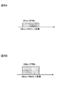
- 7A and 7B are explanatory diagrams of an example of PUCCH transmission power control according to the first aspect.
- 8A and 8B are explanatory diagrams of another example of PUCCH transmission power control according to the first aspect.
- FIG. 1 is an explanatory diagram of carrier aggregation (CA).
- CA carrier aggregation
- LTE Rel LTE Rel.
- CA carrier aggregation
- CC # 1 to CC # 5 component carriers
- CC component carriers
- UE User Equipment
- LTE Rel With 13 carrier aggregations, it is considered to bundle more than 6 CCs to further expand the bandwidth. That is, LTE Rel. In 13 carrier aggregation, it is considered to expand the number of CCs (cells) that can be set per user terminal to 6 or more (CA enhancement). For example, as shown in FIG. 1, when 32 CCs (CC # 1 to CC # 32) are bundled, a maximum band of 640 MHz can be secured.
- LAA License-Assisted Access
- the transmission method for example, format and transmission power
- LTE Rel. 10-12 the existing system
- the user terminal transmits uplink control information (UCI) using an uplink control channel (PUCCH: Physical plink Control Channel).
- UCI includes acknowledgment information (HARQ-ACK: Hybrid Automatic Repeat request-ACK) for downlink shared channel (PDSCH) of each CC and channel state information (CSI: Channel State) indicating the channel state.
- HARQ-ACK Hybrid Automatic Repeat request-ACK
- CSI Channel State
- SR Scheduling Request
- PUCCH formats 1 / 1a / 1b, 2 / 2a / 2b and 3 are supported as PUCCH formats (hereinafter referred to as PUCCH formats).
- PUCCH format 1 is used for transmission of SR.
- 1b / 3 based on PUCCH format 1a / 1b / channel selection is used for transmission of HARQ-ACK of 5 CC or less.
- PUCCH format 2 / 2a / 2b is used for transmission of CSI of a specific CC.
- the PUCCH format 2a / 2b may be used for transmission of HARQ-ACK in addition to CSI of a specific CC.
- PUCCH format 3 may be used for transmission of SR and / or CSI in addition to HARQ-ACK.
- FIG. 2 is a diagram illustrating a configuration example of PUCCH format 3 having a maximum payload among existing PUCCH formats.
- PUCCH format 3 UCI (for example, up to 5 CC HARQ-ACK) of up to 10 bits in FDD and up to 22 bits in TDD can be transmitted.
- PUCCH format 3 includes two demodulation reference signals (DMRS: DeModulation Reference Signal) and five SC-FDMA (Single Carrier Frequency Division Multiple Access) symbols per slot. The same bit string is mapped to each SC-FDMA symbol of each slot, and is multiplied by a spreading code (orthogonal code, also called OCC: Orthogonal Cover Code) in order to multiplex a plurality of user terminals.
- DMRS DeModulation Reference Signal
- SC-FDMA Single Carrier Frequency Division Multiple Access
- cyclic shifts also referred to as cyclic shifts or CSs
- CSs cyclic shifts
- orthogonal codes and cyclic shifts it is possible to code division multiplex (CDM) up to five PUCCH formats 3 on the same resource (PRB).
- CDM code division multiplex
- HARQ bit sequences can be orthogonally multiplexed using different spreading codes (OCC) for each user terminal
- DMRSs can be orthogonally multiplexed using different CS sequences for each user terminal.
- the PUCCH format 3 cannot transmit UCI for all scheduled CCs due to a lack of payload. Is assumed.
- a PUCCH format capable of transmitting 64 bits is required.
- PUCCH capable of transmitting 128 bits (when spatial bundling is applied) or 256 bits Formatting is required.
- a PUCCH (hereinafter referred to as a new PUCCH format) having a larger number of bits (payload, capacity) that can be transmitted than the existing PUCCH format so that UCI (for example, HARQ-ACK) of 6 CC or more can be transmitted. It is being considered.
- the transmission power of PUCCH is controlled based on the PUCCH format and the amount of information (payload) transmitted in the PUCCH format. Specifically, PUCCH transmission power P PUCCH (i) in subframe i is controlled based on Equation (1).
- P CMAX, c (i) is the maximum transmission power in subframe i of serving cell (also referred to as CC, cell, etc.) c.
- P 0_PUCCH is a parameter (offset) notified by an upper layer.
- PL c is a path loss of the user terminal in the serving cell c.
- h (n CQI , n HARQ , n SR ) (hereinafter also simply referred to as “h”) is a value (offset) depending on the PUCCH format.
- n CQI is the number of bits of CQI.
- n HARQ is the number of bits of HARQ-ACK.
- n SR is the number of bits of the SR field for making a scheduling request. It can be said that h is an offset based on the payload of the PUCCH format.
- h 0.
- h (n HARQ ⁇ 1) / 2.
- CP normal cyclic prefix
- h (n HARQ + n SR ⁇ 1) / 3.
- h (n HARQ + n SR ⁇ 1) / 2.
- h (n HARQ + n SR + n CQI ⁇ 1) / 3.
- h (n HARQ + n SR + n CQI ⁇ 1) / 2.
- ⁇ F_PUCCH (F) is a parameter (offset) based on the PUCCH format, and is notified by the higher layer.
- ⁇ TxD (F ′) is a parameter (offset) based on the presence / absence of transmission diversity (transmission at two antenna ports), and is notified by the upper layer.
- g (i) is a cumulative value of the TPC command.
- the present inventors have conceived of controlling the transmission power of the PUCCH in consideration of the configuration of the new PUCCH format when the number of CCs that can be set per user terminal is expanded to 6 or more.
- the CC may also be called a cell, a serving cell, or the like.
- the new PUCCH format is a transmission format in which the number of bits (payload, capacity) that can be transmitted is larger than that of the existing PUCCH format.
- the new PUCCH format may be called PUCCH format 4, large-capacity PUCCH format, extended PUCCH format, new format, or the like.
- the maximum number of bits that can be transmitted is 128 bits or more
- the number of transmission bits including HARQ-ACK and / or SR is a predetermined value (for example, 23 bits) or more.
- a cyclic redundancy check (CRC) is added to the HARQ-ACK transmission
- the number of transmission bits including HARQ-ACK and / or SR is greater than or equal to a predetermined value (for example, 23 bits).
- TBCC Transmission-Biting Convolutional Coding
- the number (type) of the new PUCCH format may be plural or one.
- the number of bits (payload) that can be transmitted such as the first new PUCCH format capable of transmitting 6CC HARQ-ACK and the second new PUCCH format capable of transmitting HARQ-ACK up to 32CC.
- a plurality of new PUCCH formats may be defined.
- a single new PUCCH format may be defined to prevent control complexity.
- the position and number of DMRSs arranged in the new PUCCH format may be the same as or different from those in PUCCH format 3. If the number of DMRSs arranged in the new PUCCH format is increased, channel estimation can be performed with high accuracy even in a low SINR environment or a high-speed moving environment. On the other hand, when the number of DMRSs is reduced, the payload (the number of bits that can be transmitted) can be increased, so that a higher coding gain can be easily obtained.
- FIG. 3 is a diagram showing a first configuration example (DMRS position and number) of the new PUCCH format.
- DMRSs may be arranged in the second and sixth SC-FDMA symbols (time symbols) of each slot, as in PUCCH format 3 (see FIG. 2).
- DMRS may be arranged in the fourth SC-FDM symbol of each slot.
- the position of the DMRS in the new PUCCH format is not limited to the positions shown in FIGS. 3A and 3B, and may be any SC-FDMA symbol in each slot.
- the number of DMRSs in the new PUCCH format is not limited to the number shown in FIGS. 3A and 3B (2 or 1 per slot), and may be 3 or more per slot.
- the number of frequency resources (also referred to as physical resource blocks (PRB), resource blocks, etc., hereinafter referred to as PRB) used in the new PUCCH format may be the same as PUCCH format 3 or larger than PUCCH format 3. May be. If the number of PRBs used in the new PUCCH format is increased, the payload per PRB is reduced, so that the coding gain can be increased while the overhead is increased.
- PRB physical resource blocks
- FIG. 4 is a diagram showing a second configuration example (number of PRBs) of the new PUCCH format.
- the new PUCCH format as in PUCCH format 3 (see FIG. 2), 1 PRB per slot may be used, and frequency hopping may be applied between slots.
- a plurality of PRBs (3 PRBs in FIG. 4) may be used per slot, and frequency hopping may be applied between the slots.
- the number of PRBs used in the new PUCCH format is not limited to the numbers shown in FIGS. 4A and 4B, and may be 2 PRBs per slot or 4 PRBs or more. 4A and 4B, frequency hopping is applied between slots, but the frequency hopping may not be applied. Further, the position and number of DMRSs are not limited to those shown in FIGS. 4A and 4B.
- a plurality of user terminals may be code division multiplexed (CDM), frequency division multiplexed (FDM), and / or time division multiplexed (TDM).
- CDM code division multiplexed
- FDM frequency division multiplexed
- TDM time division multiplexed
- a plurality of user terminals can be accommodated in the same PRB, but the payload per user terminal becomes small and it is difficult to obtain a coding gain.
- FIG. 5 is a diagram illustrating a third configuration example of the new PUCCH format (a method for multiplexing a plurality of user terminals).
- a plurality of user terminals may be code division multiplexed.
- UCIs of a plurality of user terminals are orthogonally multiplexed using different spreading codes (OCC) for each user terminal, and different cyclic shifts are applied to each user terminal.
- OCC spreading codes
- DMRS of a plurality of user terminals may be orthogonally multiplexed.
- a plurality of user terminals may be frequency division multiplexed. Specifically, UCI and DMRS of a plurality of user terminals may be mapped to different PRBs.
- the multiplexing method of a plurality of user terminals in the new PUCCH format is not limited to the multiplexing method shown in FIGS. 4A and 4B.
- a plurality of user terminals may be time division multiplexed, or time division multiplexed and frequency division multiplexed.
- a plurality of user terminals may be space-division multiplexed.
- the spreading factor (orthogonal code length) used in the new PUCCH format may be the same as that of PUCCH format 3 or may be reduced as compared with PUCCH format 3.
- the spreading factor used in the new PUCCH format is reduced, the payload (number of bits that can be transmitted) per user terminal increases, while the number of user terminals that can be multiplexed decreases.
- FIG. 6 is a diagram showing a fourth configuration example (spreading factor) of the new PUCCH format.
- the new PUCCH format as in PUCCH format 3, the same bit string is mapped to each SC-FDMA symbol excluding DMRS, and each user terminal is multiplexed to multiplex a plurality of user terminals. Different spreading codes may be multiplied.
- a different bit string may be mapped to each SC-FDMA symbol excluding DMRS by setting the spreading factor to 1, for example.
- the bit sequence length that can be transmitted is five times that of FIG. 6A, but the number of user terminals that can be multiplexed is limited to one.
- the modulation method used in the new PUCCH format may be BPSK (Binary Phase Shift Keying) or QPSK (Quadrature Phase Shift Keying) used in the existing PUCCH format, or a multi-value of 16 QAM (Quadrature Amplitude Modulation) or more.
- a modulation method may be used.
- a reference signal other than DMRS for example, SRS: Sounding Reference Signal
- SRS Sounding Reference Signal
- the user terminal in which uplink carrier aggregation is set may be set to the conventional PUCCH format or the new PUCCH format in each of two or more CCs.
- two or more cell groups (CG) including each CC in which the PUCCH format is set are set in the user terminal, and HARQ-ACK feedback control is performed in each PUCCH format for each CG.
- the user terminal performs the multiplication of the number of PRBs (number of resource blocks) constituting the PUCCH format, the compensation coefficient set smaller than 1 and the path loss, and the CRC in the PUCCH format.
- the transmission power of PUCCH is controlled based on at least one of a payload including bits and a payload not including CRC bits in the PUCCH format.
- transmission power control based on the number of PRBs (first mode), transmission power control based on the multiplication result of a compensation coefficient set smaller than 1 and a path loss (second mode), based on the presence or absence of CRC bits
- first mode transmission power control based on the number of PRBs
- second mode transmission power control based on the multiplication result of a compensation coefficient set smaller than 1
- second mode transmission power control based on the presence or absence of CRC bits
- the transmission power control (third aspect) will be described in detail. Note that the transmission power control according to the first to third aspects may be used alone, or may be used in combination of at least two.
- the transmission power control according to the present embodiment is not limited to the first to third aspects.
- the transmission power of the PUCCH includes the configuration of the above-described new PUCCH format (for example, the location and number of DMRS (FIG. 3), the number of PRBs (FIG. 4), and a multiplexing scheme of a plurality of user terminals (FIG. 5).
- Various control may be performed based on the presence / absence of CRC bits, the position and number of SRS, the spreading factor (FIG. 6), the modulation scheme, the mapping order of information bit sequences to radio resources, and the like.
- formulas (2) to (5) described later are merely examples, and parameters may be added / deleted / changed.
- the calculation of the power headroom is also performed on the assumption of the corresponding transmission power control. That is, when the user terminal applies transmission power control according to the present embodiment, the maximum power in subframe i of serving cell (also referred to as CC, cell, etc.) c is used for calculation of power headroom to be reported to the radio base station. A value obtained by subtracting the transmission power calculated based on the transmission power control according to the present embodiment from the transmission power P CMAX, c (i) can be reported as a power headroom to the radio base station.
- Power Headroom is surplus transmission power of the user terminal.
- the surplus transmission power may be calculated based on the maximum transmission power and the PUSCH transmission power (for example, by subtracting the PUSCH transmission power from the maximum transmission power) (type 1), or the maximum transmission power and PUSCH.
- the transmission power of PUCCH for example, by subtracting the transmission power of PUSCH and PUCCH from the maximum transmission power
- the surplus transmission power of the user terminal can be calculated using the transmission power of PUCCH controlled by the transmission power control according to the present embodiment.
- the user terminal may control the transmission power of the PUCCH based on the number of PRBs so that the transmission power per PRB is constant.
- the user terminal may control the transmission power of the PUCCH based on an offset that increases (may be proportional) according to the number of PRBs.
- the user terminal may control the transmission power of the PUCCH based on the payload per PRB calculated based on the number of PRBs.
- the user terminal controls the transmission power P PUCCH (i) of PUCCH in subframe i based on Equation (2).
- M PUCCH, c (i) is the number of PRBs constituting the PUCCH format in subframe i.
- M PUCCH, c (i) is 1, and in the new PUCCH format, M PUCCH, c (i) is 1 or more.
- h (n CQI , n HARQ , n SR ) / M PUCCH, c (i) is considered as a transmission power offset (parameter) depending on the payload per PRB.
- the transmission power (transmission energy) in the case of 20 bits per 1 PRB (FIG. 8B) is controlled to be larger than that in the case of 10 bits per 1 PRB (FIG. 8A). Is done.
- control is performed such that the transmission power is increased when the number of PRBs is small.
- the required received SINR that satisfies a predetermined error rate depends on the payload per received PRB number (or bandwidth).
- the transmission power of the PUCCH is controlled using an offset (for example, (h (n CQI , n HARQ , n SR ) / M PUCCH, c (i)) that increases with an increase in the payload per number of PRBs.
- the user terminal may control the PUCCH transmission power P PUCCH (i) in subframe i based on Equation (3).
- n CQI is the number of bits of CQI.
- n HARQ is the number of bits of HARQ-ACK.
- n SR is the number of bits of the SR field (hereinafter abbreviated as SR) for making a scheduling request, and is generally composed of 1 bit (in the case of PUCCH format 3, the user terminal determines whether there is an uplink scheduling request) In response, the SR bit is transmitted as 1 or 0).
- M PUCCH, c (i) is the same as the above formula (2), and P CMAX, c (i), P 0_PUCCH , PL c , ⁇ F_PUCCH (F), ⁇ TxD (F ′), g ( Since i) is the same as the above formula (1), description thereof is omitted.
- the number of CQI bits per PRB (for example, n CQI / M PUCCH, c (i)), HARQ-ACK per PRB is used as an offset that increases with an increase in payload per PRB.
- the function h based on the number of bits (for example, n HARQ / M PUCCH, c (i)) and the SR per PRB (for example, n SR / M PUCCH, c (i)) is used.
- the offset h can be more appropriately expressed as a function of the payload per PRB, so the payload per PRB Therefore, it is possible to more appropriately set a transmission power offset that conforms to the required SINR corresponding to the.
- the transmission power offset is expressed as h (n CQI , n HARQ , n SR , MPUCC, c (i)), and as a function of the PRB number of CQI, HARQ, SR payload and PUCCH, as a more general notation Also good.
- the user terminal can determine the number of PRBs constituting the PUCCH format based on notification information by higher layer signaling and / or downlink control information (DCI) transmitted by the downlink control channel (PDCCH or EPDCCH). May be determined.
- DCI downlink control information
- the notification information (control information) by the higher layer signaling includes, for example, the number of CCs set in the user terminal, the maximum number of MIMO (Multiple Input and Multiple Output) layers per CC (transmission mode (TM)), At least one UL-DL configuration (configuration of uplink subframe and downlink subframe in TDD) per CC may be included.
- MIMO Multiple Input and Multiple Output
- TDD transmission mode
- the DCI includes the total number of CCs scheduled in the user terminal (TDAI: Total Downlink Assignment Indicator), the cumulative number of scheduled CCs (ADAI: Accumulated Downlink Assignment Indicator), the user terminal. May include at least one of bitmaps indicating CCs to be scheduled among the CCs set in. Note that these pieces of information may be included in DCI for scheduling PDSCH.
- the user terminal determines a payload based on notification information by higher layer signaling or / and the DCI, and determines the number of PRBs constituting the new PUCCH format based on the determined payload. May be.
- the number of PRBs constituting the PUCCH format may be notified directly to the user terminal by higher layer signaling.
- the PRB number is quasi-statically fixed regardless of the dynamically changed payload.
- the new PUCCH format is configured with a plurality of PRBs.
- a performance improvement effect can be expected.
- ⁇ Second aspect> In the second mode, transmission power control based on a multiplication result of a compensation coefficient set smaller than 1 and a path loss will be described.
- the new PUCCH format is configured to perform frequency division multiplexing and / or time division multiplexing of a plurality of user terminals (see FIG. 5B), as in the case of code division multiplexing of a plurality of user terminals (see FIG. 5A), Intersymbol interference (in-cell perspective problem) due to the difference in reception quality at the radio base station between user terminals does not occur.
- the compensation coefficient (hereinafter referred to as path loss compensation coefficient) ⁇ multiplied by the path loss PL c is fixed to 1, and the reception quality (target received power) at the radio base station is made constant. There is no need to make it.
- the transmission power of PUCCH is controlled based on the multiplication result.
- the path loss compensation coefficient ⁇ when the path loss compensation coefficient ⁇ is fixed to 1, the reception quality (target received power) at the radio base station is constant regardless of the magnitude of the path loss (that is, the distance from the cell center). .
- the path loss compensation coefficient ⁇ when the path loss compensation coefficient ⁇ is set to be smaller than 1, a user terminal with a smaller path loss (closer to the cell center) has a higher transmission power and better reception quality at the radio base station.
- the transmission power can be increased as the path loss is smaller. Since the user terminal with a smaller path loss (closer to the center of the cell) is more likely to perform downlink scheduling, the above control can improve the throughput of user terminals with good reception quality and improve best effort. be able to.
- the user terminal may control the transmission power P PUCCH (i) of PUCCH in subframe i based on equation (4).
- ⁇ is a path loss compensation coefficient, and 0 ⁇ ⁇ ⁇ 1.
- ⁇ 1 in the existing PUCCH format and ⁇ ⁇ 1 in the new PUCCH format.
- P CMAX, c (i) P 0 — PUCCH , PL c , h (n CQI , n HARQ , n SR ), ⁇ F — PUCCH (F), ⁇ TxD (F ′), g (i) Since this is the same as 1), the description is omitted.
- the value of the path loss compensation coefficient ⁇ smaller than 1 may be notified to the user terminal by higher layer signaling.
- the value of the path loss compensation coefficient ⁇ of each new PUCCH format may be notified to the user terminal by higher layer signaling. In this case, the value of the path loss compensation coefficient ⁇ may be different for each new PUCCH format.
- a plurality of path loss compensation coefficient ⁇ values that differ depending on the payload (size of information bit sequence) included in one new PUCCH format may be notified to the user terminal by higher layer signaling.
- the transmission power of the PUCCH using the PUCCH format is controlled based on the multiplication result of the path loss compensation coefficient ⁇ and the path loss set to be smaller than 1, so that the path loss becomes smaller.
- the transmission power increases. As a result, the throughput of the user terminal with good reception quality can be improved, and the best effort can be enhanced.
- an error in the information bit can be easily detected in the radio base station by adding a CRC bit to the information bit.
- a radio base station detects a CRC error in the CQI, it can prevent scheduling based on erroneous CQI information by regarding this as invalid information.
- a radio base station detects a CRC error in HARQ-ACK, it can avoid missing a retransmission request from the terminal by regarding all the HARQ-ACK bits included as NACK.
- the number of information bits to which CRC bits are added is not limited to 23 or more bits. That is, the predetermined number may be any of 1-22, or may be 24 or more.
- the error detection by the CRC bit can prevent the radio base station from erroneously detecting the NACK transmitted from the user terminal as an ACK (NACK-to-ACK error), and thus the probability that the retransmission request from the user terminal is missed.
- NACK-to-ACK error the probability that the retransmission request from the user terminal is missed. The effect of improving throughput can be expected.
- a user terminal controls the transmission power of PUCCH based on the payload containing a CRC bit, or based on the payload which does not contain a CRC bit.
- the user terminal transmits PUCCH transmission power based on a payload including the information bits and the CRC bits. May be controlled. Since it is possible to set appropriate transmission power according to the actual payload by using the payload including the CRC bits, it is easy to achieve the required SINR in the radio base station.
- the user terminal may control the transmission power P PUCCH (i) of PUCCH in subframe i based on equation (5).
- h (n CQI , n HARQ , n SR , n CRC ) is an offset based on the payload including the CRC bits.
- n CQI is the number of bits of CQI.
- n HARQ is the number of bits of HARQ-ACK.
- n SR is the number of bits in the SR field for making a scheduling request, and is generally composed of 1 bit (in the case of PUCCH format 3, the terminal sets the SR bit according to the presence or absence of an uplink scheduling request to 1 or Send as 0).
- the n CRC is the number of CRC bits added to information bits including at least one of HARQ-ACK, CQI, and SR.
- the number of CRC bits may be a fixed value such as 8 bits or 16 bits, for example.
- h (n CQI , n HARQ , n SR , n CRC ) may consider the weight of CRC bits for information bits (at least one of CQI, HARQ-ACK, SR). .
- the value of h (n CQI , n HARQ , n SR , n CRC ) may be defined similarly to h (n CQI , n HARQ , n SR ) in Expression (1).
- P CMAX, c (i), P 0_PUCCH , PL c , ⁇ F_PUCCH (F), ⁇ TxD (F ′), and g (i) are the same as the above formula (1), and thus the description thereof is omitted. .
- the user terminal may control the transmission power of PUCCH based on a payload that does not include CRC bits. Based on a payload that does not include a CRC bit, it is possible to set an appropriate transmission power according to an increase or decrease in information bits without being affected by the CRC bit.
- the user terminal can transmit the PUCCH transmission power P PUCCH in subframe i based on the above equation (1).
- (I) may be controlled.
- FIG. 10 is a diagram showing the relationship between payload and transmission power when a fixed-length CRC bit is added to 22 or more HARQ-ACK bits in the new PUCCH format.
- A when an offset based on a payload including a CRC is used (A), transmission power for a fixed-length CRC bit is added with 22 bits as a boundary.
- B when an offset based on a payload that does not include a CRC is used (B), transmission power increases according to the number of HARQ-ACK bits.
- the PUCCH format is A transmission power suitable for a case where a CRC bit is added to a predetermined number of information bits or more can be set.
- wireless communication system Wireless communication system
- the radio communication method according to each aspect of the present invention is applied.
- wireless communication method which concerns on each said aspect may be applied independently, respectively, and may be applied in combination.
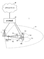
- FIG. 11 is a diagram illustrating an example of a schematic configuration of a wireless communication system according to an embodiment of the present invention.
- carrier aggregation (CA) and / or dual connectivity (DC) in which a plurality of basic frequency blocks (component carriers) each having a system bandwidth (for example, 20 MHz) of the LTE system as one unit are applied.
- the wireless communication system 1 may be referred to as SUPER 3G, LTE-A (LTE-Advanced), IMT-Advanced, 4G, 5G, FRA (Future Radio Access), or the like.
- a radio communication system 1 shown in FIG. 11 includes a radio base station 11 that forms a macro cell C1, and radio base stations 12a to 12c that are arranged in the macro cell C1 and form a small cell C2 narrower than the macro cell C1. . Moreover, the user terminal 20 is arrange
- the user terminal 20 can be connected to both the radio base station 11 and the radio base station 12. It is assumed that the user terminal 20 uses the macro cell C1 and the small cell C2 that use different frequencies simultaneously by CA or DC. In addition, the user terminal 20 can apply CA or DC using a plurality of cells (CC) (for example, six or more CCs).
- CC cells
- Communication between the user terminal 20 and the radio base station 11 can be performed using a carrier having a relatively low frequency band (for example, 2 GHz) and a narrow bandwidth (referred to as an existing carrier or a legacy carrier).
- a carrier having a relatively high frequency band for example, 3.5 GHz, 5 GHz, etc.
- the same carrier may be used.
- the configuration of the frequency band used by each radio base station is not limited to this.
- a wired connection for example, an optical fiber compliant with CPRI (Common Public Radio Interface), an X2 interface, etc.
- a wireless connection It can be set as the structure to do.
- the radio base station 11 and each radio base station 12 are connected to the higher station apparatus 30 and connected to the core network 40 via the higher station apparatus 30.
- the upper station device 30 includes, for example, an access gateway device, a radio network controller (RNC), a mobility management entity (MME), and the like, but is not limited thereto.
- RNC radio network controller
- MME mobility management entity
- Each radio base station 12 may be connected to the higher station apparatus 30 via the radio base station 11.
- the radio base station 11 is a radio base station having a relatively wide coverage, and may be called a macro base station, an aggregation node, an eNB (eNodeB), a transmission / reception point, or the like.
- the radio base station 12 is a radio base station having local coverage, and includes a small base station, a micro base station, a pico base station, a femto base station, a HeNB (Home eNodeB), an RRH (Remote Radio Head), and transmission / reception. It may be called a point.
- the radio base stations 11 and 12 are not distinguished, they are collectively referred to as a radio base station 10.
- Each user terminal 20 is a terminal compatible with various communication methods such as LTE and LTE-A, and may include not only a mobile communication terminal but also a fixed communication terminal.
- OFDMA orthogonal frequency division multiple access
- SC-FDMA single carrier-frequency division multiple access
- OFDMA is a multi-carrier transmission scheme that performs communication by dividing a frequency band into a plurality of narrow frequency bands (subcarriers) and mapping data to each subcarrier.
- SC-FDMA is a single-carrier transmission scheme that reduces interference between terminals by dividing the system bandwidth into bands consisting of one or continuous resource blocks for each terminal and using a plurality of terminals with mutually different bands. is there.
- the uplink and downlink radio access methods are not limited to these combinations.
- downlink channels include a downlink shared channel (PDSCH) shared by each user terminal 20, a broadcast channel (PBCH: Physical Broadcast Channel), a downlink L1 / L2 control channel, and the like. Used. User data, higher layer control information, SIB (System Information Block), etc. are transmitted by PDSCH. Also, MIB (Master Information Block) is transmitted by PBCH.
- PDSCH downlink shared channel
- PBCH Physical Broadcast Channel
- SIB System Information Block
- MIB Master Information Block
- Downlink L1 / L2 control channels include downlink control channels (PDCCH (Physical Downlink Control Channel), EPDCCH (Enhanced Physical Downlink Control Channel)), PCFICH (Physical Control Format Indicator Channel), PHICH (Physical Hybrid-ARQ Indicator Channel), etc. Including. Downlink control information (DCI: Downlink Control Information) including scheduling information of PDSCH and PUSCH is transmitted by PDCCH. The number of OFDM symbols used for PDCCH is transmitted by PCFICH. The HAICH transmission confirmation information (ACK / NACK) for PUSCH is transmitted by PHICH.
- EPDCCH is frequency-division multiplexed with PDSCH (downlink shared data channel), and is used for transmission of DCI and the like in the same manner as PDCCH.
- an uplink shared channel (PUSCH: Physical Uplink Shared Channel), an uplink control channel (PUCCH: Physical Uplink Control Channel), and a random access channel (PRACH) shared by each user terminal 20 are used. Physical Random Access Channel) is used.
- PUSCH Physical Uplink Shared Channel
- PUCCH Physical Uplink Control Channel
- PRACH random access channel
- User data and higher layer control information are transmitted by the PUSCH.
- Uplink control information including at least one of delivery confirmation information (ACK / NACK) and radio quality information (CQI) is transmitted by PUSCH or PUCCH.
- a random access preamble for establishing connection with a cell is transmitted by the PRACH.
- FIG. 12 is a diagram illustrating an example of the overall configuration of a radio base station according to an embodiment of the present invention.
- the radio base station 10 includes a plurality of transmission / reception antennas 101, an amplifier unit 102, a transmission / reception unit 103, a baseband signal processing unit 104, a call processing unit 105, and a transmission path interface 106.
- each of the transmission / reception antenna 101, the amplifier unit 102, and the transmission / reception unit 103 may be configured to include one or more.
- User data transmitted from the radio base station 10 to the user terminal 20 via the downlink is input from the higher station apparatus 30 to the baseband signal processing unit 104 via the transmission path interface 106.
- PDCP Packet Data Convergence Protocol
- RLC Radio Link Control
- MAC Medium Access Control
- HARQ Hybrid Automatic Repeat reQuest
- the downlink control signal is also subjected to transmission processing such as channel coding and inverse fast Fourier transform, and is transferred to the transmission / reception unit 103.
- the transmission / reception unit 103 converts the baseband signal output by precoding for each antenna from the baseband signal processing unit 104 to a radio frequency band and transmits the converted signal.
- the radio frequency signal frequency-converted by the transmission / reception unit 103 is amplified by the amplifier unit 102 and transmitted from the transmission / reception antenna 101.
- the transmitter / receiver, the transmission / reception circuit, or the transmission / reception device can be configured based on common recognition in the technical field according to the present invention.
- the transmission / reception part 103 may be comprised as an integral transmission / reception part, and may be comprised from a transmission part and a receiving part.
- the radio frequency signal received by the transmission / reception antenna 101 is amplified by the amplifier unit 102.
- the transmission / reception unit 103 receives the uplink signal amplified by the amplifier unit 102.
- the transmission / reception unit 103 converts the frequency of the received signal into a baseband signal and outputs it to the baseband signal processing unit 104.
- the baseband signal processing unit 104 performs fast Fourier transform (FFT) processing, inverse discrete Fourier transform (IDFT: Inverse Discrete Fourier Transform) processing, and error correction on user data included in the input upstream signal.
- FFT fast Fourier transform
- IDFT inverse discrete Fourier transform
- Decoding, MAC retransmission control reception processing, RLC layer and PDCP layer reception processing are performed and transferred to the upper station apparatus 30 via the transmission path interface 106.
- the call processing unit 105 performs call processing such as communication channel setting and release, state management of the radio base station 10, and radio resource management.
- the transmission path interface 106 transmits and receives signals to and from the higher station apparatus 30 via a predetermined interface.
- the transmission path interface 106 transmits and receives (backhaul signaling) signals to and from the adjacent radio base station 10 via an interface between base stations (for example, an optical fiber compliant with CPRI (Common Public Radio Interface), X2 interface). Also good.
- CPRI Common Public Radio Interface
- X2 interface also good.
- FIG. 13 is a diagram illustrating an example of a functional configuration of the radio base station according to the present embodiment.
- FIG. 13 mainly shows functional blocks of characteristic portions in the present embodiment, and the radio base station 10 also has other functional blocks necessary for radio communication.
- the baseband signal processing unit 104 includes a control unit 301, a transmission signal generation unit 302, a mapping unit 303, and a reception signal processing unit 304.
- the control unit 301 controls the entire radio base station 10.
- the control unit 301 controls, for example, downlink signal generation by the transmission signal generation unit 302, signal mapping by the mapping unit 303, and signal reception processing by the reception signal processing unit 304.
- control unit 301 controls transmission of downlink user data (for example, modulation scheme, coding rate, resource allocation (scheduling), etc.) based on channel state information (CSI) reported from the user terminal 20. Control).
- downlink user data for example, modulation scheme, coding rate, resource allocation (scheduling), etc.
- CSI channel state information
- control unit 301 controls mapping of downlink control information (DCI) including resource allocation information (DL / UL grant) for downlink / uplink user data to the downlink control channel (PDCCH and / or EPDCCH). Further, the control unit 301 controls mapping of downlink reference signals such as CRS (Cell-specific Reference Signal) and CSI-RS (Channel State Information Reference Signal).
- DCI downlink control information
- DL / UL grant resource allocation information
- DL / UL grant resource allocation information
- CSI-RS Channel State Information Reference Signal
- control unit 301 controls carrier aggregation (CA) of the user terminal 20. Specifically, the control unit 301 determines CA application / change in the number of CCs based on CSI reported from the user terminal 20 and the like, and generates a transmission signal so as to generate information indicating the application / change.
- the unit 302 may be controlled. Note that the information indicating the application / change may be included in control information that is signaled by higher layers.
- control unit 301 may control the maximum number of MIMO per CC (transmission mode (TM)) and the UL / DL configuration per CC in TDD.
- the maximum MIMO number and UL / DL configuration may be included in control information (notification information) notified to the user terminal 20 by higher layer signaling.
- control unit 301 includes the total number of CCs scheduled for the CCs set for the user terminal 20 (TDAI), the cumulative number of CCs to be scheduled (ADAI), and the CCs set for the user terminal 20. At least one of bitmaps indicating CCs to be scheduled may be determined. Note that these pieces of information may be included in DCI for scheduling PDSCH.
- control unit 301 controls parameters used for PUCCH transmission power control (closed loop control, open loop control). Specifically, the control unit 301 determines an increase / decrease value of the transmission power control (TPC) command based on the reception quality of the uplink signal from the user terminal 20.
- the TPC command may be included in DCI transmitted to the user terminal 20 by PDCCH.
- the control unit 301 also includes a parameter based on target received power in the radio base station (for example, P 0_PUCCH ), a parameter based on the PUCCH format (for example, ⁇ F_PUCCH (F)), and a parameter based on the presence / absence of transmission diversity (for example, , ⁇ TxD (F ′)) is determined.
- P 0_PUCCH target received power in the radio base station
- F ⁇ F_PUCCH
- F a parameter based on the presence / absence of transmission diversity for example, ⁇ TxD (F ′)
- control unit 301 may determine the number of PRBs constituting the PUCCH format (first mode). The number of PRBs may be included in control information (notification information) notified to the user terminal 20 by higher layer signaling.
- control unit 301 may determine the path loss guarantee coefficient ⁇ (second mode).
- the path loss guarantee coefficient ⁇ may be included in control information (notification information) notified to the user terminal 20 by higher layer signaling.
- the control unit 301 may change whether or not the path loss guarantee coefficient ⁇ is set to be smaller than 1 according to the PUCCH format.
- the control unit 301 may determine the path loss guarantee coefficient ⁇ to be smaller than 1 in the case of the new PUCCH format, and may determine the path loss guarantee coefficient ⁇ to be 1 in the case of the existing PUCCH format.
- control unit 301 may determine the path loss guarantee coefficient ⁇ to be smaller than 1 when the new PUCCH format is configured to frequency multiplex or / and time multiplex multiple user terminals 20. In addition, when a plurality of new PUCCH formats are set, the control unit 301 may determine a different path loss guarantee coefficient ⁇ for each new PUCCH format. In addition, when a single new PUCCH format is composed of a plurality of different payloads, the control unit 301 may determine a different path loss guarantee coefficient ⁇ depending on the payload of the new PUCCH format.
- the control unit 301 can be configured by a controller, a control circuit, or a control device described based on common recognition in the technical field according to the present invention.
- the transmission signal generation unit 302 generates a downlink signal (including a downlink data signal and a downlink control signal) based on an instruction from the control unit 301 and outputs it to the mapping unit 303. Specifically, the transmission signal generation unit 302 generates a downlink data signal (PDSCH) including notification information (control information) by the above-described higher layer signaling and user data, and outputs it to the mapping unit 303. Also, the transmission signal generation unit 302 generates a downlink control signal (PDCCH) including the above-described DCI, and outputs the downlink control signal (PDCCH) to the mapping unit 303. Also, the transmission signal generation unit 302 generates downlink reference signals such as CRS and CSI-RS, and outputs them to the mapping unit 303.
- PDSCH downlink data signal
- PDCCH downlink control signal
- the transmission signal generation unit 302 generates downlink reference signals such as CRS and CSI-RS, and outputs them to the mapping unit 303.
- the transmission signal generation unit 302 can be a signal generator, a signal generation circuit, or a signal generation device described based on common recognition in the technical field according to the present invention.
- the mapping unit 303 maps the downlink signal generated by the transmission signal generation unit 302 to a predetermined radio resource based on an instruction from the control unit 301, and outputs it to the transmission / reception unit 103.
- the mapping unit 303 can be a mapper, a mapping circuit, or a mapping device described based on common recognition in the technical field according to the present invention.
- the reception signal processing unit 304 performs reception processing (for example, demapping, demodulation, decoding, etc.) on the uplink signal transmitted from the user terminal 20.
- the processing result is output to the control unit 301.
- the reception signal processing unit 304 detects the PUCCH format and performs reception processing of UCI (at least one of HARQ-ACK, CQI, and SR).
- the reception signal processing unit 304 may be composed of a signal processor, a signal processing circuit or a signal processing device, and a measuring device, a measurement circuit or a measuring device which are described based on common recognition in the technical field according to the present invention. it can.
- FIG. 14 is a diagram illustrating an example of an overall configuration of a user terminal according to an embodiment of the present invention.
- the user terminal 20 includes a plurality of transmission / reception antennas 201 for MIMO transmission, an amplifier unit 202, a transmission / reception unit 203, a baseband signal processing unit 204, and an application unit 205.
- the radio frequency signals received by the plurality of transmission / reception antennas 201 are each amplified by the amplifier unit 202.
- Each transmitting / receiving unit 203 receives the downlink signal amplified by the amplifier unit 202.
- the transmission / reception unit 203 converts the frequency of the received signal into a baseband signal and outputs it to the baseband signal processing unit 204.
- the baseband signal processing unit 204 performs FFT processing, error correction decoding, retransmission control reception processing, and the like on the input baseband signal.
- the downlink user data is transferred to the application unit 205.
- the application unit 205 performs processing related to layers higher than the physical layer and the MAC layer.
- broadcast information in the downlink data is also transferred to the application unit 205.
- uplink user data is input from the application unit 205 to the baseband signal processing unit 204.
- the baseband signal processing unit 204 performs retransmission control transmission processing (for example, HARQ transmission processing), channel coding, precoding, discrete Fourier transform (DFT) processing, IFFT processing, and the like.
- the data is transferred to the transmission / reception unit 203.
- the transmission / reception unit 203 converts the baseband signal output from the baseband signal processing unit 204 into a radio frequency band and transmits it.
- the radio frequency signal frequency-converted by the transmission / reception unit 203 is amplified by the amplifier unit 202 and transmitted from the transmission / reception antenna 201.
- the transmission / reception unit 203 can be a transmitter / receiver, a transmission / reception circuit, or a transmission / reception device described based on common recognition in the technical field according to the present invention. Further, the transmission / reception unit 203 may be configured as an integral transmission / reception unit, or may be configured from a transmission unit and a reception unit.
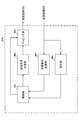
- FIG. 15 is a diagram illustrating an example of a functional configuration of the user terminal according to the present embodiment. Note that FIG. 15 mainly shows functional blocks of characteristic portions in the present embodiment, and the user terminal 20 also has other functional blocks necessary for wireless communication. As illustrated in FIG. 15, the baseband signal processing unit 204 included in the user terminal 20 includes a control unit 401, a transmission signal generation unit 402, a mapping unit 403, a reception signal processing unit 404, and a measurement unit 405. I have.
- the control unit 401 controls the entire user terminal 20.
- the control unit 401 controls, for example, signal generation by the transmission signal generation unit 402, signal mapping by the mapping unit 403, and signal reception processing by the reception signal processing unit 404.
- the control unit 401 controls the PUCCH format applied to the transmission of UCI (at least one of HARQ-ACK, CQI, and SR). Specifically, the control unit 401 determines whether to apply a new PUCCH format or an existing PUCCH format according to the number of CCs set for the user terminal 20 or the number of CCs scheduled for the user terminal 20. Also good. Further, when a plurality of new PUCCH formats are provided, the control unit 401 may determine a new PUCCH format to be applied according to the UCI payload.
- control unit 401 determines the number of PRBs constituting the PUCCH format (first mode), the multiplication result (second mode) of the path loss compensation coefficient ⁇ and path loss set to be smaller than 1, and the PUCCH format.
- the transmission power of the PUCCH is controlled based on at least one of the payload including the CRC bits (third aspect) and the payload not including the CRC bits in the PUCCH format (third aspect).
- the control unit 401 controls the transmission power of the PUCCH based on the number of PRBs so that the transmission power per PRB is constant. Also good.
- the control unit 401 may control the transmission power of the PUCCH based on the payload per PRB calculated based on the number of PRBs. For example, the control unit 401 may control the transmission power of the PUCCH using the above formula (2) or the formula (3).
- the number of PRBs constituting the PUCCH may be notified to the user terminal 20 by higher layer signaling.
- the control unit 401 may notify information by higher layer signaling (for example, the number of CCs set in the user terminal 20, the maximum number of MIMO layers per CC (TM), the UL / DL configuration per CC) or / and DCI (
- the number of PRBs constituting the PUCCH format may be determined based on the TDAI, ADIA, and bitmap).
- the control unit 401 may determine a payload based on the control information and / or DCI that is signaled by the higher layer, and may determine the number of PRBs based on the payload.
- the path loss compensation coefficient (compensation coefficient) set to be smaller than 1
- the transmission power of PUCCH is controlled.
- the control unit 401 may control the transmission power of the PUCCH using the above equation (4).
- the path loss guarantee coefficient ⁇ may be notified to the user terminal 20 by higher layer signaling.
- the control unit 401 determines the PUCCH based on the payload including the information bits and the CRC bits.
- the transmission power may be controlled.
- the control unit 401 may control the transmission power of the PUCCH using the above equation (5).
- the offset based on the payload may be set in consideration of the weight of the CRC bits with respect to the information bits.
- the user terminal controls the transmission power of the PUCCH based on a payload not including the CRC bits. May be.
- the control unit 401 may control the transmission power of the PUCCH using the above equation (1).
- control unit 401 also includes a configuration of a new PUCCH format (for example, the location and number of DMRS (FIG. 3), the number of PRBs (FIG. 4), a multiplexing scheme of a plurality of user terminals (FIG. 5), CRC
- the transmission power may be controlled variously based on the presence / absence of bits, the position and number of SRS, the spreading factor (FIG. 6), the modulation scheme, the order of mapping information bit sequences to radio resources, and the like.
- the control part 401 may calculate surplus transmission power (PH: Power Headroom) based on the transmission power and maximum transmission power of PUCCH controlled as mentioned above. The calculated surplus transmission power may be transmitted to the radio base station 10 (PHR: Power Headroom Report).
- PHR Power Headroom Report
- the control unit 401 can be configured by a controller, a control circuit, or a control device described based on common recognition in the technical field according to the present invention.
- the transmission signal generation unit 402 generates an uplink signal (including an uplink data signal and an uplink control signal) based on an instruction from the control unit 401 and outputs the uplink signal to the mapping unit 403. For example, the transmission signal generation unit 402 generates an uplink control signal (PUCCH) including UCI (at least one of HARQ-ACK, CQI, and SR).
- PUCCH uplink control signal
- the transmission signal generation unit 402 can be a signal generator, a signal generation circuit, or a signal generation device described based on common recognition in the technical field according to the present invention.
- the mapping unit 403 Based on an instruction from the control unit 401, the mapping unit 403 maps the uplink signal (uplink control signal and / or uplink data signal) generated by the transmission signal generation unit 402 to a radio resource and outputs the radio resource to the transmission / reception unit 203. To do.
- the mapping unit 403 may be a mapper, a mapping circuit, or a mapping device described based on common recognition in the technical field according to the present invention.
- the reception signal processing unit 404 performs reception processing (for example, demapping, demodulation, decoding, etc.) on downlink signals (including downlink control signals and downlink data signals).
- the reception signal processing unit 404 outputs information received from the radio base station 10 to the control unit 401.
- the received signal processing unit 404 outputs, for example, broadcast information, system information, control information by higher layer signaling such as RRC signaling, DCI, and the like to the control unit 401.
- the received signal processing unit 404 can be configured by a signal processor, a signal processing circuit, or a signal processing device described based on common recognition in the technical field according to the present invention. Further, the reception signal processing unit 404 can constitute a reception unit according to the present invention.
- the measurement unit 405 measures the channel state based on a reference signal (for example, CSI-RS) from the radio base station 10 and outputs the measurement result to the control unit 401. Note that the channel state measurement may be performed for each CC.
- a reference signal for example, CSI-RS
- the measuring unit 405 can be composed of a signal processor, a signal processing circuit or a signal processing device, and a measuring device, a measurement circuit or a measuring device which are explained based on common recognition in the technical field according to the present invention.
- each functional block is realized by one physically coupled device, or may be realized by two or more physically separated devices connected by wire or wirelessly and by a plurality of these devices. Good.
- the radio base station 10 and the user terminal 20 are realized using hardware such as ASIC (Application Specific Integrated Circuit), PLD (Programmable Logic Device), and FPGA (Field Programmable Gate Array). May be.
- the radio base station 10 and the user terminal 20 are each a computer device including a processor (CPU: Central Processing Unit), a communication interface for network connection, a memory, and a computer-readable storage medium holding a program. It may be realized. That is, the radio base station, user terminal, and the like according to an embodiment of the present invention may function as a computer that performs processing of the radio communication method according to the present invention.
- Computer-readable recording media include, for example, flexible disks, magneto-optical disks, ROM (Read Only Memory), EPROM (Erasable Programmable ROM), CD-ROM (Compact Disc-ROM), RAM (Random Access Memory), A storage medium such as a hard disk.
- the program may be transmitted from a network via a telecommunication line.
- the radio base station 10 and the user terminal 20 may include an input device such as an input key and an output device such as a display.
- the functional configurations of the radio base station 10 and the user terminal 20 may be realized by the hardware described above, may be realized by a software module executed by a processor, or may be realized by a combination of both.
- the processor controls the entire user terminal by operating an operating system. Further, the processor reads programs, software modules and data from the storage medium into the memory, and executes various processes according to these.
- the program may be a program that causes a computer to execute the operations described in the above embodiments.
- the control unit 401 of the user terminal 20 may be realized by a control program stored in a memory and operated by a processor, and may be realized similarly for other functional blocks.
- software, instructions, etc. may be transmitted / received via a transmission medium.
- software may use websites, servers, or other devices using wired technology such as coaxial cable, fiber optic cable, twisted pair and digital subscriber line (DSL) and / or wireless technology such as infrared, wireless and microwave.
- wired technology such as coaxial cable, fiber optic cable, twisted pair and digital subscriber line (DSL) and / or wireless technology such as infrared, wireless and microwave.
- DSL digital subscriber line
- wireless technology such as infrared, wireless and microwave.
- the channel and / or symbol may be a signal (signaling).
- the signal may be a message.
- the component carrier (CC) may be called a carrier frequency, a cell, or the like.
- information, parameters, and the like described in this specification may be represented by absolute values, may be represented by relative values from a predetermined value, or may be represented by other corresponding information.
- the radio resource may be indicated by an index.
- notification of predetermined information is not limited to explicitly performed, but is performed implicitly (for example, by not performing notification of the predetermined information). May be.
- notification of information is not limited to the aspect / embodiment described in this specification, and may be performed by other methods.
- notification of information includes physical layer signaling (for example, DCI (Downlink Control Information), UCI (Uplink Control Information)), upper layer signaling (for example, RRC (Radio Resource Control) signaling, MAC (Medium Access Control) signaling), It may be implemented by broadcast information (MIB (Master Information Block), SIB (System Information Block)), other signals, or a combination thereof.
- the RRC signaling may be referred to as an RRC message, and may be, for example, an RRC connection setup (RRCConnectionSetup) message, an RRC connection reconfiguration (RRCConnectionReconfiguration) message, or the like.
- Each aspect / embodiment described in this specification includes LTE (Long Term Evolution), LTE-A (LTE-Advanced), SUPER 3G, IMT-Advanced, 4G, 5G, FRA (Future Radio Access), CDMA2000, UMB (Ultra Mobile Broadband), IEEE 802.11 (Wi-Fi), IEEE 802.16 (WiMAX), IEEE 802.20, UWB (Ultra-WideBand), Bluetooth (registered trademark), and other appropriate systems
- LTE Long Term Evolution
- LTE-A LTE-Advanced
- SUPER 3G IMT-Advanced
- 4G 5G
- FRA Full Radio Access
- CDMA2000 Code Division Multiple Access 2000
- UMB User Mobile Broadband
- IEEE 802.11 Wi-Fi
- IEEE 802.16 WiMAX
- IEEE 802.20 UWB (Ultra-WideBand)
- Bluetooth registered trademark
Landscapes
- Engineering & Computer Science (AREA)
- Computer Networks & Wireless Communication (AREA)
- Signal Processing (AREA)
- Computer Security & Cryptography (AREA)
- Mobile Radio Communication Systems (AREA)
Abstract
ユーザ端末あたりに設定可能なコンポーネントキャリア(CC)数が既存システムより拡張される場合に、上り制御チャネルの送信電力制御を適切に行うこと。本発明のユーザ端末は、上り制御チャネルを送信する送信部と、前記上り制御チャネルの送信電力を制御する制御部と、を具備し、前記制御部は、前記上り制御チャネルのフォーマットを構成するリソースブロック数と、前記フォーマットにおける巡回冗長検査(CRC)ビットを含むペイロードと、の少なくとも一つに基づいて、前記上り制御チャネルの送信電力を制御することを特徴とする。
Description
本発明は、次世代移動通信システムにおけるユーザ端末、無線基地局及び無線通信方法に関する。
UMTS(Universal Mobile Telecommunication System)ネットワークにおいて、さらなる高速データレート、低遅延などを目的としてロングタームエボリューション(LTE:Long Term Evolution)が仕様化された(非特許文献1)。LTE(LTE Rel.8ともいう)からのさらなる広帯域化および高速化を目的として、LTEアドバンスト(LTE Rel.10、11又は12ともいう)が仕様化され、後継システム(LTE Rel.13等ともいう)も検討されている。
LTE Rel.10/11のシステム帯域は、LTE Rel.8のシステム帯域を一単位とする少なくとも1つのコンポーネントキャリア(CC:Component Carrier)を含んでいる。このように、複数のコンポーネントキャリアを集めて広帯域化することをキャリアアグリゲーション(CA:Carrier Aggregation)という。
また、LTE Rel.8から12のLTEでは、事業者に免許された周波数帯、すなわちライセンスバンドにおいて排他的な運用がなされることを想定して仕様化が行われた。ライセンスバンドとしては、たとえば800MHz、2GHzまたは1.7GHzなどが使用される。
Rel.13以降のLTEでは、免許不要の周波数帯、すなわちアンライセンスバンドにおける運用もターゲットとして検討されている。アンライセンスバンドとしては、たとえばWi-Fiと同じ2.4GHzまたは5GHz帯などが使用される。Rel.13 LTEでは、ライセンスバンドとアンライセンスバンドの間でのキャリアアグリゲーション(LAA:License-Assisted Access)を検討対象としているが、将来的にデュアルコネクティビティやアンライセンスバンドのスタンドアローンも検討対象となる可能性がある。
LTE Rel.10-12のキャリアアグリゲーションでは、ユーザ端末あたりに設定可能なコンポーネントキャリア(CC)数が最大5個に制限されている。LTE Rel.13以降のキャリアアグリゲーションでは、更なる帯域拡張を実現するため、ユーザ端末あたりに設定可能なCC数を6個以上に拡張することが検討されている。
ところで、既存システム(Rel.10-12)では、各CCの下り信号に対する送達確認情報(HARQ-ACK)が上り制御チャネル(PUCCH:Physical Uplink Control Channel)で送信される。この場合、ユーザ端末は、5CC以下を前提とする既存PUCCHフォーマット(例えば、PUCCHフォーマット1a/1b/3など)を用いて、上記送達確認情報を送信する。
しかしながら、既存PUCCHフォーマットは、CC数が6個以上に拡張される場合のように、多数のCCの送達確認情報を送信する場合には適合しないことが想定される。そこで、CC数が6個以上に拡張される場合に適するPUCCHフォーマット(以下、新PUCCHフォーマットという)の導入が検討されている。一方で、新PUCCHフォーマットを導入する場合、上り制御チャネルの送信電力を適切に制御できなくなる恐れがある。
本発明はかかる点に鑑みてなされたものであり、ユーザ端末あたりに設定可能なコンポーネントキャリア(CC)数が既存システムより拡張される場合に、上り制御チャネルの送信電力を適切に制御可能なユーザ端末、無線基地局及び無線通信方法を提供することを目的とする。
本発明のユーザ端末の一態様は、上り制御チャネルを送信する送信部と、前記上り制御チャネルの送信電力を制御する制御部と、を具備し、前記制御部は、前記上り制御チャネルのフォーマットを構成するリソースブロック数と、前記フォーマットにおける巡回冗長検査(CRC)ビットを含むペイロードと、の少なくとも一つに基づいて、前記上り制御チャネルの送信電力を制御することを特徴とする。
本発明によれば、ユーザ端末あたりに設定可能なコンポーネントキャリア(CC)数が既存システムより拡張される場合に、上り制御チャネルの送信電力制御を適切に行うことができる。
図1は、キャリアアグリゲーション(CA)の説明図である。図1に示すように、LTE Rel.12までのCAでは、LTE Rel.8のシステム帯域を一単位とするコンポーネントキャリア(CC)が最大5個(CC#1~CC#5)束ねられる。すなわち、LTE Rel.12までのキャリアアグリゲーションでは、ユーザ端末(UE:User Equipment)あたりに設定可能なCC数は、最大5個に制限される。
一方、LTE Rel.13のキャリアアグリゲーションでは、6個以上のCCを束ねて、更なる帯域拡張を図ることが検討されている。すなわち、LTE Rel.13のキャリアアグリゲーションでは、ユーザ端末あたりに設定可能なCC(セル)数を6個以上に拡張すること(CA enhancement)が検討されている。例えば、図1に示すように、32個のCC(CC#1~CC#32)を束ねる場合、最大640MHzの帯域を確保可能となる。
このように、ユーザ端末あたりに設定可能なCC数を拡張することにより、より柔軟且つ高速な無線通信を実現することが期待されている。また、このようなCC数の拡張は、ライセンスバンドとアンライセンスバンドとの間のキャリアアグリゲーション(LAA:License-Assisted Access)による広帯域化に効果的である。例えば、ライセンスバンドの5個のCC(=100MHz)とアンライセンスバンドの15個のCC(=300MHz)とを束ねる場合、400MHzの帯域を確保可能となる。
一方で、ユーザ端末に設定可能なCC数が6個以上(例えば、32個)に拡張される場合、既存システム(LTE Rel.10-12)の送信方法(例えば、フォーマットや送信電力など)をそのまま適用することが困難となる。
例えば、既存システム(LTE Rel.10-12)では、ユーザ端末は、上り制御情報(UCI)を上り制御チャネル(PUCCH:Physical plink Control Channel)を用いて送信する。ここで、UCIは、各CCの下り共有チャネル(PDSCH:Physical Downlink Shared Channel)に対する送達確認情報(HARQ-ACK:Hybrid Automatic Repeat request-ACK)と、チャネル状態を示すチャネル状態情報(CSI:Channel State Information)と、上り共有チャネル(PUSCH:Physical Uplink Shared Channel)のスケジューリング要求(SR:Scheduling Request)と、の少なくとも一つを含む。
既存システムでは、PUCCHのフォーマット(以下、PUCCHフォーマットという)として、PUCCHフォーマット1/1a/1b、2/2a/2b及び3(総称して既存PUCCHフォーマットという)がサポートされている。PUCCHフォーマット1は、SRの送信に用いられる。PUCCHフォーマット1a/1b/チャネルセレクションに基づく1b/3は、5CC以下のHARQ-ACKの送信に用いられる。PUCCHフォーマット2/2a/2bは、特定のCCのCSIの送信に用いられる。PUCCHフォーマット2a/2bは、特定のCCのCSIに加えて、HARQ-ACKの送信に用いられてもよい。PUCCHフォーマット3は、HARQ-ACKに加えて、SR及び/又はCSIの送信に用いられてもよい。
図2は、既存PUCCHフォーマットのうちで最大ペイロードのPUCCHフォーマット3の構成例を示す図である。PUCCHフォーマット3では、FDDにおいて10ビット、TDDにおいて22ビットまでのUCI(例えば、最大5CCのHARQ-ACK)を送信可能である。図2に示すように、PUCCHフォーマット3は、スロットあたり2つの復調用参照信号(DMRS:DeModulation Reference Signal)と、5つのSC-FDMA(Single Carrier Frequency Divisional Multiple Access)シンボルで構成される。各スロットの各SC-FDMAシンボルには同一ビット列がマッピングされ、複数のユーザ端末を多重するために拡散符号(直交符号、OCC:Orthogonal Cover Codeとも呼ぶ)が乗算されている。
また、各スロットの各DMRSにはユーザ端末間で異なる巡回シフト(サイクリックシフト、CSとも呼ぶ)が適用されている。直交符号とサイクリックシフトを適用することにより、最大で5つのPUCCHフォーマット3を同一のリソース(PRB)に符号分割多重(CDM)することが可能となる。例えば、ユーザ端末毎に異なる拡散符号(OCC)を用いてHARQビット列を直交多重し、ユーザ端末毎に異なるCS系列を用いてDMRSを直交多重することができる。
しかしながら、ユーザ端末あたりに設定可能なCC数が6以上(例えば、32個)に拡張される場合、上記PUCCHフォーマット3では、ペイロードの不足により、スケジューリングされる全CCについてのUCIを送信できなくなることが想定される。
例えば、FDDにおいて、32CCについて2コードワード(トランスポートブロック)のHARQ-ACKを送信する場合、64ビットを送信可能なPUCCHフォーマットが必要となる。また、TDDにおいて、32CCについて2コードワードのHARQ-ACKを送信する場合で1上りサブフレームに4下りサブフレームが対応する場合、128ビット(空間バンドリング適用時)又は256ビットを送信可能なPUCCHフォーマットが必要となる。
そこで、6CC以上のUCI(例えば、HARQ-ACK)を送信できるように、既存PUCCHフォーマットよりも送信可能なビット数(ペイロード、容量)が大きいPUCCH(以下、新PUCCHフォーマットという)を導入することが検討されている。
ところで、既存システム(LTE Rel.10-12)では、PUCCHの送信電力は、PUCCHフォーマットと当該PUCCHフォーマットで送信される情報量(ペイロード)とに基づいて制御される。具体的には、サブフレームiにおけるPUCCHの送信電力PPUCCH(i)は、式(1)に基づいて制御される。

ここで、PCMAX,c(i)は、サービングセル(CC、セルなどともいう)cのサブフレームiにおける最大送信電力である。P0_PUCCHは、上位レイヤにより通知されるパラメータ(オフセット)である。PLcは、サービングセルcにおけるユーザ端末のパスロスである。
また、h(nCQI,nHARQ,nSR)(以下、単に、「h」ともいう)は、PUCCHフォーマットに依存する値(オフセット)である。nCQIは、CQIのビット数である。nHARQは、HARQ-ACKのビット数である。nSRは、スケジューリング要求を行うためのSRフィールドのビット数である。hは、PUCCHフォーマットのペイロードに基づくオフセットともいえる。
例えば、PUCCHフォーマット1/1a/1bの場合、h=0である。チャネルセレクションに基づくPUCCHフォーマット1bで下りキャリアアグリゲーションを行う場合、h=(nHARQ-1)/2である。PUCCHフォーマット2/2a/2bでノーマルサイクリックプリフィクス(CP)の場合、nCQI≧4であればh=10log10(nCQI/4)であり、nCQI<4であればh=0である。PUCCHフォーマット2で拡張CPの場合、nCQI+nHARQ≧4であればh=10log10(nCQI+nHARQ/4)であり、nCQI+nHARQ<4であればh=0である。
また、PUCCHフォーマット3でHARQ-ACKとSRとを送信する場合で2アンテナを用いるか或いは11ビットより大きい場合、h=(nHARQ+nSR-1)/3である。PUCCHフォーマット3でHARQ-ACKとSRとを送信する場合で1アンテナを用い、かつ、11ビットより大きくない場合、h=(nHARQ+nSR-1)/2である。また、PUCCHフォーマット3でHARQ-ACKとSRとCSIを送信する場合で2アンテナを用いるか或いは11ビットより大きい場合、h=(nHARQ+nSR+nCQI-1)/3である。PUCCHフォーマット3でHARQ-ACKとSRとCSIを送信する場合で1アンテナを用い、かつ、11ビットより大きくない場合、h=(nHARQ+nSR+nCQI-1)/2である。
また、ΔF_PUCCH(F)は、PUCCHフォーマットに基づくパラメータ(オフセット)であり、上位レイヤにより通知される。また、ΔTxD(F’)は、送信ダイバーシチの有無(2アンテナポートでの送信)に基づくパラメータ(オフセット)であり、上位レイヤにより通知される。g(i)は、TPCコマンドの累積値である。
なお、上記PUCCHフォーマット1a/1b、2/2a/2b及び3では、複数のユーザ端末が符号分割多重(CDM)されるため、上記式(1)では、パスロスPLcに乗算されるパスロス補償係数αは1に固定される。
しかしながら、上記式(1)では、上述の新PUCCHフォーマットを導入する場合、PUCCHの送信電力を適切に制御できなくなる恐れがある。そこで、本発明者らは、ユーザ端末あたりに設定可能なCC数が6個以上に拡張される場合、新PUCCHフォーマットの構成を考慮して、PUCCHの送信電力を制御することを着想した。
以下、本発明の一実施の形態について詳細に説明する。なお、以下においては、キャリアアグリゲーションにおいてユーザ端末あたりに設定可能なCC数が32個である例を説明するが、これに限られない。また、CCは、セル、サービングセルなどと呼ばれてもよい。
(新PUCCHフォーマットの構成)
図3-6を参照し、本実施の形態で用いられる新PUCCHフォーマットの構成について説明する。上述のように、新PUCCHフォーマットは、既存PUCCHフォーマットよりも送信可能なビット数(ペイロード、容量)が大きい送信フォーマットである。なお、新PUCCHフォーマットは、PUCCHフォーマット4、大容量PUCCHフォーマット、拡張PUCCHフォーマット、新フォーマット等と呼ばれてもよい。
図3-6を参照し、本実施の形態で用いられる新PUCCHフォーマットの構成について説明する。上述のように、新PUCCHフォーマットは、既存PUCCHフォーマットよりも送信可能なビット数(ペイロード、容量)が大きい送信フォーマットである。なお、新PUCCHフォーマットは、PUCCHフォーマット4、大容量PUCCHフォーマット、拡張PUCCHフォーマット、新フォーマット等と呼ばれてもよい。
また、新PUCCHフォーマットでは、(1)送信可能な最大ビット数が128ビット以上であること、(2)HARQ-ACK及び/またはSRを含む送信ビット数が所定値(例えば、23ビット)以上である場合、HARQ-ACK送信に巡回冗長検査(CRC:Cyclic Redundancy Code)が付加されること、(3)HARQ-ACK及び/またはSRを含む送信ビット数が所定値(例えば、23ビット)以上である場合、LTE Release 8で導入されたTBCC(Tail-Biting Convolutional Coding)及びレートマッチングが適用されること、などが定められてもよい。
また、新PUCCHフォーマットの数(種類)は、複数であってもよいし、1つであってもよい。例えば、32CCのHARQ-ACKを送信可能な新PUCCHフォーマットを用いて6CCのHARQ-ACKを伝送する場合、オーバーヘッドが増加する。このため、例えば、6CCのHARQ-ACKを伝送可能な第1の新PUCCHフォーマットと、32CCまでのHARQ-ACKを伝送可能な第2の新PUCCHフォーマットのように、送信可能なビット数(ペイロード)が異なる複数の新PUCCHフォーマットが規定されてもよい。或いは、制御の複雑化を防止するために、単一の新PUCCHフォーマットが規定されてもよい。
また、新PUCCHフォーマットで配置されるDMRSの位置及び数は、PUCCHフォーマット3と同一であってもよいし、異なってもよい。新PUCCHフォーマットで配置されるDMRSの数を増やすと、低SINR環境や高速移動環境においても高い精度でチャネル推定を行うことができる。一方、DMRSの数を減らすと、ペイロード(伝送可能なビット数)を増やすことができるため、より高い符号化利得を得易くなる。
図3は、新PUCCHフォーマットの第1の構成例(DMRSの位置及び数)を示す図である。図3Aに示すように、新PUCCHフォーマットでは、PUCCHフォーマット3(図2参照)と同様に、各スロットの2番目及び6番目のSC-FDMAシンボル(時間シンボル)にDMRSが配置されてもよい。或いは、図3Bに示すように、新PUCCHフォーマットでは、各スロットの4番目のSC-FDMシンボルにDMRSが配置されてもよい。
なお、新PUCCHフォーマットにおけるDMRSの位置は、図3A及び3Bに示す位置に限られず、各スロットの任意のSC-FDMAシンボルであってよい。また、新PUCCHフォーマットにおけるDMRSの数は、図3A及び3Bに示す数(スロットあたり2又は1)に限られず、スロットあたり3以上であってもよい。
また、新PUCCHフォーマットに用いられる周波数リソース(物理リソースブロック(PRB)、リソースブロック等ともいう。以下、PRBという)の数は、PUCCHフォーマット3と同一であってもよいし、PUCCHフォーマット3より大きくてもよい。新PUCCHフォーマットに用いられるPRB数を増やすと、PRBあたりのペイロードが減少するので、符号化利得を高めることができる一方で、オーバーヘッドが増加する。
図4は、新PUCCHフォーマットの第2の構成例(PRB数)を示す図である。図4Aに示すように、新PUCCHフォーマットでは、PUCCHフォーマット3(図2参照)と同様に、スロットあたり1PRBが用いられ、スロット間で周波数ホッピングが適用されてもよい。或いは、図4Bに示すように、新PUCCHフォーマットでは、スロットあたり複数のPRB(図4では、3PRB)が用いられ、スロット間で周波数ホッピングが適用されてもよい。
なお、新PUCCHフォーマットで用いられるPRB数は、図4A及び4Bに示す数に限られず、スロットあたり2PRBであってもよいし、4PRB以上であってもよい。また、図4A及び4Bでは、スロット間で周波数ホッピングが適用されるが、当該周波数ホッピングは適用されなくともよい。また、DMRSの位置及び数は、図4A及び4Bに示すものに限られない。
また、新PUCCHフォーマットでは、複数のユーザ端末が符号分割多重(CDM)されてもよいし、周波数分割多重(FDM)又は/及び時分割多重(TDM)されてもよい。符号分割多重の場合、同一のPRBに複数のユーザ端末を収容できる一方で、ユーザ端末あたりのペイロードが小さくなり、符号化利得が得難くなる。
図5は、新PUCCHフォーマットの第3の構成例(複数のユーザ端末の多重方法)を示す図である。図5Aに示すように、新PUCCHフォーマットでは、複数のユーザ端末が符号分割多重されてもよい。具体的には、PUCCHフォーマット3(図2参照)と同様に、ユーザ端末毎に異なる拡散符号(OCC)を用いて複数のユーザ端末のUCIを直交多重し、ユーザ端末毎に異なる巡回シフトを適用して複数のユーザ端末のDMRSを直交多重してもよい。
或いは、図5Bに示すように、新PUCCHフォーマットでは、複数のユーザ端末が周波数分割多重されてもよい。具体的には、複数のユーザ端末のUCI及びDMRSがそれぞれ異なるPRBにマッピングされてもよい。
なお、新PUCCHフォーマットにおける複数のユーザ端末の多重方法は、図4A及び4Bに示す多重方法に限られない。例えば、複数のユーザ端末が時分割多重されてもよいし、時分割多重及び周波数分割多重されてもよい。また、複数のユーザ端末が空間分割多重されてもよい。
また、新PUCCHフォーマットで用いられる拡散率(直交符号長)は、PUCCHフォーマット3と同一であってもよいし、PUCCHフォーマット3よりも減らしてもよい。新PUCCHフォーマットに用いられる拡散率を減らすと、ユーザ端末あたりのペイロード(送信可能なビット数)が増加する一方で、多重可能なユーザ端末数は減少する。
図6は、新PUCCHフォーマットの第4の構成例(拡散率)を示す図である。図6Aに示すように、新PUCCHフォーマットでは、PUCCHフォーマット3と同様に、DMRSを除いた各SC-FDMAシンボルには同一のビット列がマッピングされ、複数のユーザ端末を多重するためにユーザ端末毎に異なる拡散符号が乗算されてもよい。或いは、図6Bに示すように、拡散率を例えば1とすることにより、DMRSを除いた各SC-FDMAシンボルに異なるビット列がマッピングされてもよい。図6Bの場合、図6Aと比較して伝送可能なビット系列長は5倍となるが、多重可能なユーザ端末数は1に限られる。
なお、新PUCCHフォーマットでは、PUCCHフォーマット3(図2参照)においてユーザ端末毎に異なる拡散符号を用いて複数のユーザ端末を直交多重する代わりに、同一ユーザ端末に設定されたCC毎に異なる拡散符号を用いて当該ユーザ端末の複数のCCのUCIを直交多重してもよい。
また、新PUCCHフォーマットで用いられる変調方式は、既存PUCCHフォーマットで用いられるBPSK(Binary Phase Shift Keying)やQPSK(Quadrature Phase Shift Keying)であってもよいし、16QAM(Quadrature Amplitude Modulation)以上の多値変調方式であってもよい。
以上の新PUCCHフォーマットの構成例は、それぞれ単独で用いられてもよいし、少なくとも一つを組み合わせて用いられてもよいし、上記以外に適宜変更されてもよい。例えば、新PUCCHフォーマットでは、DMRS以外の参照信号(例えば、SRS:Sounding Reference Signal)が配置されてもよい。
また、上りリンクキャリアアグリゲーションが設定されたユーザ端末は、2つ以上のCCそれぞれにおいて、従来のPUCCHフォーマットまたは新PUCCHフォーマットが設定されてもよい。この場合、ユーザ端末には、PUCCHフォーマットが設定されたそれぞれのCCを含む2つ以上のセルグループ(CG)が設定され、CGごとにそれぞれのPUCCHフォーマットでHARQ-ACKフィードバック制御が行われる。
(無線通信方法)
本実施の形態に係る無線通信方法では、ユーザ端末は、PUCCHフォーマットを構成するPRB数(リソースブロック数)と、1よりも小さく設定される補償係数とパスロスとの乗算結果と、PUCCHフォーマットにおけるCRCビットを含むペイロードと、PUCCHフォーマットにおけるCRCビットを含まないペイロードと、の少なくとも一つに基づいて、PUCCHの送信電力を制御する。
本実施の形態に係る無線通信方法では、ユーザ端末は、PUCCHフォーマットを構成するPRB数(リソースブロック数)と、1よりも小さく設定される補償係数とパスロスとの乗算結果と、PUCCHフォーマットにおけるCRCビットを含むペイロードと、PUCCHフォーマットにおけるCRCビットを含まないペイロードと、の少なくとも一つに基づいて、PUCCHの送信電力を制御する。
以下では、PRB数に基づく送信電力制御(第1の態様)、1よりも小さく設定される補償係数とパスロスとの乗算結果に基づく送信電力制御(第2の態様)、CRCビットの有無に基づく送信電力制御(第3の態様)について詳述する。なお、第1-第3の態様に係る送信電力制御は、それぞれ、単独で用いられてもよいし、少なくとも2つを組み合わせて用いられてもよい。
なお、本実施の形態に係る送信電力制御は、第1-第3の態様に限られない。本実施の形態において、PUCCHの送信電力は、上述した新PUCCHフォーマットの構成(例えば、DMRSの位置及び数(図3)、PRB数(図4)、複数のユーザ端末の多重方式(図5)、CRCビットの有無、SRSの位置及び数、拡散率(図6)、変調方式、情報ビット系列の無線リソースへのマッピング順序など)に基づいて、様々に制御されてもよい。また、後述する式(2)-(5)は、例示にすぎず、パラメータが追加/削除/変更されてもよい。
また、本実施の形態に係る送信電力制御を適用する場合、Power headroomの計算においても、対応する送信電力制御を前提に計算するものとする。すなわち、ユーザ端末は、本実施の形態に係る送信電力制御を適用する場合、その無線基地局に報告するPower headroomの計算には、サービングセル(CC、セルなどともいう)cのサブフレームiにおける最大送信電力PCMAX,c(i)から本実施の形態に係る送信電力制御に基づき計算される送信電力を引いたものをPower headroomとして無線基地局に報告するものとすることができる。
ここで、Power Headroomとは、ユーザ端末の余剰送信電力である。当該余剰送信電力は、最大送信電力とPUSCHの送信電力とに基づいて(例えば、最大送信電力からPUSCHの送信電力を減算して)算出されてもよいし(タイプ1)、最大送信電力とPUSCH及びPUCCHの送信電力とに基づいて(例えば、最大送信電力からPUSCH及びPUCCHの送信電力を減算して)算出されてもよい(タイプ2)。タイプ2の場合、本実施の形態に係る送信電力制御により制御されるPUCCHの送信電力を用いて、ユーザ端末の余剰送信電力を算出できる。
<第1の態様>
第1の態様では、PRB数に基づく送信電力制御について説明する。新PUCCHフォーマットが複数のPRBで構成される場合(図4参照)、PRBあたりのペイロードを下げることができるため、符号化利得を高めることができる。一方、新PUCCHフォーマットが複数のPRBで構成される場合、上記式(1)を用いると、PRBあたりの送信電力(送信エネルギー)がPRB数分の1となるため、送信電力制御による性能改善効果を得られない恐れがある。そこで、第1の態様では、ユーザ端末は、PUCCHフォーマットを構成するPRB数に基づいて、PUCCHの送信電力を制御する。
第1の態様では、PRB数に基づく送信電力制御について説明する。新PUCCHフォーマットが複数のPRBで構成される場合(図4参照)、PRBあたりのペイロードを下げることができるため、符号化利得を高めることができる。一方、新PUCCHフォーマットが複数のPRBで構成される場合、上記式(1)を用いると、PRBあたりの送信電力(送信エネルギー)がPRB数分の1となるため、送信電力制御による性能改善効果を得られない恐れがある。そこで、第1の態様では、ユーザ端末は、PUCCHフォーマットを構成するPRB数に基づいて、PUCCHの送信電力を制御する。
具体的には、PUCCHフォーマットが複数のPRBで構成される場合、ユーザ端末は、PRBあたりの送信電力が一定となるように、上記PRB数に基づいて、PUCCHの送信電力を制御してもよい。例えば、ユーザ端末は、PRB数に応じて増加(比例でもよい)するオフセットに基づいて、PUCCHの送信電力を制御してもよい。
また、新PUCCHフォーマットが複数のPRBで構成される場合、ユーザ端末は、上記PRB数に基づいて算出されるPRBあたりのペイロードに基づいて、PUCCHの送信電力を制御してもよい。
例えば、ユーザ端末は、式(2)に基づいて、サブフレームiにおけるPUCCHの送信電力PPUCCH(i)を制御する。

ここで、MPUCCH,c(i)は、サブフレームiにおいてPUCCHフォーマットを構成するPRB数である。例えば、既存PUCCHフォーマットでは、MPUCCH,c(i)は1であり、新PUCCHフォーマットでは、MPUCCH,c(i)は1以上である。なお、PCMAX,c(i)、P0_PUCCH、PLc、h(nCQI,nHARQ,nSR)、ΔF_PUCCH(F)、ΔTxD(F’)、g(i)は、上記式(1)と同じであるため、説明を省略する。
上記式(2)では、10log10(MPUCCH,c(i))が考慮される。このため、図7Aに示すように、1PRBで構成されるPUCCHフォーマットの送信電力をA(dBm)とすると、2PRBで構成されるPUCCHフォーマットの送信電力は、A+10log102(≒3)(dBm)となる。この場合、図7Bに示すように、2PRBのPUCCHフォーマットの送信電力は、1PRBのPUCCHフォーマットの送信電力の2倍となる。
このように、PRB数の増加に応じて増加するオフセット(例えば、10log10(MPUCCH,c(i))を用いてPUCCHの送信電力を制御することにより、PRBあたりの送信電力の減少を防止できる。このため、新PUCCHフォーマットが複数のPRBで構成される場合にも、性能改善効果を期待できる。
また、上記式(2)では、PRBあたりのペイロードに依存する送信電力オフセット(パラメータ)として、h(nCQI,nHARQ,nSR)/MPUCCH,c(i)が考慮される。このため、新PUCCHフォーマットが2PRBで構成される場合、1PRBあたり20ビットの場合(図8B)の送信電力(送信エネルギー)は、1PRBあたり10ビットの場合(図8A)よりも大きくなるように制御される。また、同一ペイロードでPRB数が異なる新PUCCHフォーマットを比較すると、PRB数が少ない場合の方が、送信電力が大きくなるよう制御される。
一般に、所定の誤り率(例えばビット誤り率またはブロック誤り率など)を満たす所要受信SINRは、受信PRB数(または帯域幅)あたりのペイロードに依存する。このように、PRB数あたりのペイロードの増加に応じて増加するオフセット(例えば、(h(nCQI,nHARQ,nSR)/MPUCCH,c(i))を用いてPUCCHの送信電力を制御することにより、PRBあたりのペイロード増減に起因する所要SINRの増減に適切に対応する送信電力オフセットを加えることができる。このため、新PUCCHフォーマットが複数のPRBで構成される場合にも、性能改善効果を期待できる。
或いは、ユーザ端末は、式(3)に基づいて、サブフレームiにおけるPUCCHの送信電力PPUCCH(i)を制御してもよい。

ここで、nCQIは、CQIのビット数である。nHARQは、HARQ-ACKのビット数である。nSRは、スケジューリング要求を行うためのSRフィールドのビット数(以下、SRと略する)であり、一般に1ビットで構成される(PUCCHフォーマット3の場合、ユーザ端末は、上りリンクのスケジューリング要求有無に応じて当該SRビットを1また0として送信する)。なお、MPUCCH,c(i)は、上記式(2)と同じであり、PCMAX,c(i)、P0_PUCCH、PLc、ΔF_PUCCH(F)、ΔTxD(F’)、g(i)は、上記式(1)と同じであるため、説明を省略する。
上記式(3)では、PRB数あたりのペイロードの増加に応じて増加するオフセットとして、PRBあたりのCQIのビット数(例えば、nCQI/MPUCCH,c(i))、PRBあたりのHARQ-ACKのビット数(例えば、nHARQ/MPUCCH,c(i))、PRBあたりのSR(例えば、nSR/MPUCCH,c(i))に基づく関数hが用いられる。この場合、上記オフセットh(nCQI,nHARQ,nSR)/MPUCCH,c(i)と比較して、オフセットhをPRBあたりのペイロードの関数としてより適切に表現できるため、PRBあたりのペイロードに応じた所要SINRに適合する送信電力オフセットをより適切に設定することができる。
あるいは、送信電力オフセットをh(nCQI,nHARQ,nSR,MPUCCH,c(i))と表記し、CQI、HARQ、SRペイロードおよびPUCCHのPRB数の関数として、より一般的な表記としてもよい。
なお、第1の態様において、ユーザ端末は、上位レイヤシグナリングよる通知情報又は/及び下り制御チャネル(PDCCH又はEPDCCH)により送信される下り制御情報(DCI)に基づいて、PUCCHフォーマットを構成するPRB数を決定してもよい。
ここで、上記上位レイヤシグナリングによる通知情報(制御情報)には、例えば、ユーザ端末に設定されるCC数、CCあたりの最大MIMO(Multiple Input and Multiple Output)レイヤ数(送信モード(TM))、CCあたりのUL-DL構成(TDDにおける上りサブフレームと下りサブフレームとの構成)の少なくとも一つが含まれてもよい。
また、上記DCIには、ユーザ端末に設定されるCCのうちでスケジューリングされるCCの総数(TDAI:Total Downlink Assignment Indicator)、スケジューリングされるCCの累積数(ADAI:Accumulated Downlink Assignment Indicator)、ユーザ端末に設定されるCCのうちでスケジューリングされるCCを示すビットマップの少なくとも一つが含まれてもよい。なお、これらの情報は、PDSCHをスケジューリングするDCIに含まれてもよい。
或いは、第1の態様において、ユーザ端末は、上位レイヤシグナリングによる通知情報又は/及び上記DCIに基づいてペイロードを決定し、決定されたペイロードに基づいて、新PUCCHフォーマットを構成するPRB数を決定してもよい。
或いは、第1の態様において、PUCCHフォーマットを構成するPRB数は、上位レイヤシグナリングにより、直接ユーザ端末に通知されてもよい。この場合、動的に変更されるペイロードに関わらず、PRB数は準静的に固定となる。
以上のように、第1の態様では、PUCCHフォーマットを構成するPRB数に基づいて、新PUCCHフォーマットを用いたPUCCHの送信電力が制御されるので、新PUCCHフォーマットが複数のPRBで構成される場合にも、性能改善効果を期待できる。
<第2の態様>
第2の態様では、1よりも小さく設定される補償係数とパスロスとの乗算結果に基づく送信電力制御を説明する。新PUCCHフォーマットが複数のユーザ端末を周波数分割多重又は/及び時間分割多重するように構成される場合(図5B参照)、複数のユーザ端末を符号分割多重する場合(図5A参照)のように、無線基地局における受信品質がユーザ端末間で異なることによる符号間干渉(セル内の遠近問題)は発生しない。このため、上記式(1)のように、パスロスPLcに乗算される補償係数(以下、パスロス補償係数)αを1に固定して、無線基地局における受信品質(目標受信電力)を一定するにする必要はない。
第2の態様では、1よりも小さく設定される補償係数とパスロスとの乗算結果に基づく送信電力制御を説明する。新PUCCHフォーマットが複数のユーザ端末を周波数分割多重又は/及び時間分割多重するように構成される場合(図5B参照)、複数のユーザ端末を符号分割多重する場合(図5A参照)のように、無線基地局における受信品質がユーザ端末間で異なることによる符号間干渉(セル内の遠近問題)は発生しない。このため、上記式(1)のように、パスロスPLcに乗算される補償係数(以下、パスロス補償係数)αを1に固定して、無線基地局における受信品質(目標受信電力)を一定するにする必要はない。
そこで、第2の態様では、PUCCHフォーマットが複数のユーザ端末を周波数分割多重又は/及び時間分割多重するように構成される場合、1より小さく設定されるパスロス補償係数(補償係数)αとパスロスとの乗算結果に基づいて、PUCCHの送信電力を制御する。
図9に示すように、パスロス補償係数αを1に固定する場合、パスロスの大きさ(すなわち、セル中央からの距離)に関わらず、無線基地局における受信品質(目標受信電力)は一定である。一方、パスロス補償係数αを1よりも小さく設定する場合、パスロスが小さい(セル中央に近い)ユーザ端末ほど、送信電力が大きくなり、無線基地局における受信品質が良くなる。
このように、1より小さく設定されるパスロス補償係数とパスロスとの乗算結果に基づいて送信電力を制御することにより、パスロスが小さいほど送信電力を大きくできる。パスロスが小さい(セル中央に近い)ユーザ端末ほど多くの下りスケジューリングが行われる可能性が高いことから、上記制御により、受信品質が良いユーザ端末のスループットを向上させることができ、ベストエフォート性を高めることができる。
例えば、ユーザ端末は、式(4)に基づいて、サブフレームiにおけるPUCCHの送信電力PPUCCH(i)を制御してもよい。

ここで、αは、パスロス補償係数であり、0≦α≦1である。例えば、既存PUCCHフォーマットでは、α=1であり、新PUCCHフォーマットでは、α<1である。なお、PCMAX,c(i)、P0_PUCCH、PLc、h(nCQI,nHARQ,nSR)、ΔF_PUCCH(F)、ΔTxD(F’)、g(i)は、上記式(1)と同じであるため、説明を省略する。
第2の態様において、1より小さいパスロス補償係数αの値は、上位レイヤシグナリングによりユーザ端末に通知(configure)されてもよい。上位レイヤシグナリングによりパスロス補償係数αの値が通知されない場合、或いは、既存PUCCHフォーマットを用いる場合、ユーザ端末は、α=1としてもよい。
また、ユーザ端末は、PUCCHフォーマットやペイロードに基づいて、パスロス補償係数αの値を制御してもよい。例えば、ユーザ端末は、既存PUCCHフォーマットを用いる場合、α=1とし、新PUCCHフォーマットを用いる場合、上位レイヤシグナリングにより通知される値にαを設定してもよい。
また、複数の新PUCCHフォーマットが導入される場合、各新PUCCHフォーマットのパスロス補償係数αの値が、上位レイヤシグナリングによりユーザ端末に通知されてもよい。この場合、パスロス補償係数αの値は、新PUCCHフォーマット毎に異なってもよい。
或いは、1つの新PUCCHフォーマットに含まれるペイロード(情報ビット系列のサイズ)に応じて異なる複数のパスロス補償係数αの値が、上位レイヤシグナリングによりユーザ端末に通知されてもよい。
以上のように、第2の態様では、1より小さく設定されるパスロス補償係数αとパスロスとの乗算結果に基づいて、PUCCHフォーマットを用いたPUCCHの送信電力が制御されるので、パスロスが小さくなるほど上記送信電力は大きくなる。この結果、受信品質が良いユーザ端末のスループットを向上させるこができ、ベストエフォート性を高めることができる。
<第3の態様>
第3の態様では、CRCビットの有無に基づく送信電力制御を説明する。新PUCCHフォーマットでは、所定数以上の情報ビット(例えば、CQI、HARQ-ACK、SRの少なくとも一つ)を伝送する場合、当該情報ビット(例えば、CQI、HARQ-ACK、SRの少なくとも一つ)にCRCビットを付加することが検討されている。
第3の態様では、CRCビットの有無に基づく送信電力制御を説明する。新PUCCHフォーマットでは、所定数以上の情報ビット(例えば、CQI、HARQ-ACK、SRの少なくとも一つ)を伝送する場合、当該情報ビット(例えば、CQI、HARQ-ACK、SRの少なくとも一つ)にCRCビットを付加することが検討されている。
これは、情報ビットにCRCビットを付加することにより、無線基地局において情報ビットの誤りを簡便に検出可能となるためである。無線基地局は、CQIにCRCエラーを検出した場合、これを無効な情報とみなすことで誤ったCQI情報に基づくスケジューリングを防ぐことができる。また、無線基地局は、HARQ-ACKにCRCエラーを検出した場合、含まれるすべてのHARQ-ACKビットをNACKとみなすことで端末からの再送要求を取り逃がさずに済むことができる。
なお、以下では、CRCビットが23ビット以上の情報ビットに付加される場合を説明するが、CRCビットが付加される情報ビット数は、23ビット以上に限られない。すなわち、上記所定数は、1-22のいずれであってもよいし、24以上であってもよい。
例えば、新PUCCHフォーマットで、23ビット以上のHARQ-ACKビットを送信する場合、当該HARQ-ACKビットに8ビット以上のCRCを付加することが検討されている。この場合、CRCビットによる誤り検出により、無線基地局がユーザ端末から送信されたNACKをACKと誤検出すること(NACK-to-ACK誤り)を防止できるので、ユーザ端末からの再送要求を取り逃がす確率を低減し、スループットの向上効果が期待できる。
このように、新PUCCHフォーマットが所定数以上の情報ビットにCRCビットを付加するように構成される場合、CRCビットをペイロードとして考慮するか否かが問題となる。そこで、第3の態様では、ユーザ端末は、CRCビットを含むペイロードに基づいて、或いは、CRCビットを含まないペイロードに基づいて、PUCCHの送信電力を制御する。
具体的には、PUCCHフォーマットが所定数以上の情報ビットにCRCビットを付加するように構成される場合、ユーザ端末は、当該情報ビットと当該CRCビットとを含むペイロードに基づいて、PUCCHの送信電力を制御してもよい。CRCビットを含むペイロードに基づくことで、実際のペイロードに応じた適切な送信電力を設定できるので、無線基地局における所要SINRを達成し易くなる。
例えば、ユーザ端末は、式(5)に基づいて、サブフレームiにおけるPUCCHの送信電力PPUCCH(i)を制御してもよい。

ここで、h(nCQI,nHARQ,nSR,nCRC)は、CRCビットを含むペイロードに基づくオフセットである。nCQIは、CQIのビット数である。nHARQは、HARQ-ACKのビット数である。nSRは、スケジューリング要求を行うためのSRフィールドのビット数であり、一般に1ビットで構成される(PUCCHフォーマット3の場合、端末は、上りリンクのスケジューリング要求有無に応じて当該SRビットを1また0として送信する)。nCRCは、HARQ-ACK、CQI、SRの少なくとも一つを含む情報ビットに付加されるCRCビット数である。CRCビット数は、例えば、8ビットや16ビットなどの固定値であってもよい。
また、新PUCCHフォーマットの場合、h(nCQI,nHARQ,nSR,nCRC)では、情報ビット(CQI、HARQ-ACK、SRの少なくとも一つ)に対するCRCビットの重みが考慮されてもよい。例えば、h(nCQI,nHARQ,nSR,nCRC)=(nCQI+nHARQ+nSR+nCRC-1)/3のように、CQI、HARQ、SRのペイロードとCRCのペイロードが同等の重みでオフセットに寄与する数式であってもよいし、h(nCQI,nHARQ,nSR,nCRC)=(nCQI+nHARQ+nSR+nCRC/8-1)/3のように、CQI、HARQ、SRのペイロードに対してCRCのペイロードの寄与を小さくする重みが乗算される数式であってもよい。CQI、HARQ、SRのペイロードとCRCのペイロードが同等の重みでオフセットに寄与する数式とした場合、CRC含むペイロードに最適な送信電力オフセットを設定できることから、CRCチェック前に所定の誤り率を満たす所要SINRを達成できる送信電力にすることが容易となる。一方、CQI、HARQ、SRのペイロードに対してCRCのペイロードの寄与を小さくする重みが乗算される数式とした場合、実際には情報ペイロードではないCRCの分の送信電力オフセットを小さくすることで、他セル干渉等の増加を抑えることが可能となる。
一方、既存PUCCHフォーマットの場合、式(1)のh(nCQI,nHARQ,nSR)と同様に、h(nCQI,nHARQ,nSR,nCRC)の値が定義されてもよい。なお、PCMAX,c(i)、P0_PUCCH、PLc、ΔF_PUCCH(F)、ΔTxD(F’)、g(i)は、上記式(1)と同じであるため、説明を省略する。
或いは、PUCCHフォーマットが所定数以上の情報ビットにCRCビットを付加するように構成される場合、ユーザ端末は、CRCビットを含まないペイロードに基づいて、PUCCHの送信電力を制御してもよい。CRCビットを含まないペイロードに基づくことで、CRCビットに影響されずに、情報ビットの増減に応じた適切な送信電力を設定できる。
この場合、新PUCCHフォーマット用のh(nCQI,nHARQ,nSR)を新たに定義することで、ユーザ端末は、上記式(1)に基づいて、サブフレームiにおけるPUCCHの送信電力PPUCCH(i)を制御してもよい。例えば、新PUCCHフォーマットの場合、h(nCQI,nHARQ,nSR)=(nCQI+nHARQ+nSR-1)/3やh(nCQI,nHARQ,nSR)=2×(nCQI+nHARQ+nSR-1)/3、などであってもよい。
図10は、新PUCCHフォーマットにおいて22ビット以上のHARQ-ACKビットに固定長のCRCビットを付加する場合のペイロードと送信電力との関係を示す図である。図10に示すように、CRCを含むペイロードに基づくオフセットを用いる場合(A)、22ビットを境界に、固定長のCRCビット分の送信電力が加算される。一方、CRCを含まないペイロードに基づくオフセットを用いる場合(B)、HARQ-ACKビット数に応じて送信電力が増加する。なお、SRが設定されたサブフレームの場合、SRの1ビットが加わるため、CRCを含むペイロードに基づくオフセットを用いる場合(A)、23ビットを境界に、固定長のCRCビット分の送信電力が加算される。一方、CRCを含まないペイロードに基づくオフセットを用いる場合(B)、HARQ-ACKビットに応じて送信電力が増加する。
以上のように、第3の態様では、CRCビットを含むペイロードに基づいて、或いは、CRCビットを含まないペイロードに基づいて、PUCCHフォーマットを用いたPUCCHの送信電力が制御されるので、PUCCHフォーマットが所定数以上の情報ビットにCRCビットを付加するように構成される場合に適した送信電力を設定できる。
(無線通信システム)
以下、本発明の一実施形態に係る無線通信システムの構成について説明する。この無線通信システムでは、本発明の上記各態様に係る無線通信方法が適用される。なお、上記各態様に係る無線通信方法は、それぞれ単独で適用されてもよいし、組み合わせて適用されてもよい。
以下、本発明の一実施形態に係る無線通信システムの構成について説明する。この無線通信システムでは、本発明の上記各態様に係る無線通信方法が適用される。なお、上記各態様に係る無線通信方法は、それぞれ単独で適用されてもよいし、組み合わせて適用されてもよい。
図11は、本発明の一実施形態に係る無線通信システムの概略構成の一例を示す図である。無線通信システム1では、LTEシステムのシステム帯域幅(例えば、20MHz)を1単位とする複数の基本周波数ブロック(コンポーネントキャリア)を一体としたキャリアアグリゲーション(CA)及び/又はデュアルコネクティビティ(DC)を適用することができる。なお、無線通信システム1は、SUPER 3G、LTE-A(LTE-Advanced)、IMT-Advanced、4G、5G、FRA(Future Radio Access)などと呼ばれても良い。
図11に示す無線通信システム1は、マクロセルC1を形成する無線基地局11と、マクロセルC1内に配置され、マクロセルC1よりも狭いスモールセルC2を形成する無線基地局12a~12cとを備えている。また、マクロセルC1及び各スモールセルC2には、ユーザ端末20が配置されている。
ユーザ端末20は、無線基地局11及び無線基地局12の双方に接続することができる。ユーザ端末20は、異なる周波数を用いるマクロセルC1とスモールセルC2を、CA又はDCにより同時に使用することが想定される。また、ユーザ端末20は、複数のセル(CC)(例えば、6個以上のCC)を用いてCA又はDCを適用することができる。
ユーザ端末20と無線基地局11との間は、相対的に低い周波数帯域(例えば、2GHz)で帯域幅が狭いキャリア(既存キャリア、Legacy carrierなどと呼ばれる)を用いて通信を行うことができる。一方、ユーザ端末20と無線基地局12との間は、相対的に高い周波数帯域(例えば、3.5GHz、5GHzなど)で帯域幅が広いキャリアが用いられてもよいし、無線基地局11との間と同じキャリアが用いられてもよい。なお、各無線基地局が利用する周波数帯域の構成はこれに限られない。
無線基地局11と無線基地局12との間(又は、2つの無線基地局12間)は、有線接続(例えば、CPRI(Common Public Radio Interface)に準拠した光ファイバ、X2インターフェースなど)又は無線接続する構成とすることができる。
無線基地局11及び各無線基地局12は、それぞれ上位局装置30に接続され、上位局装置30を介してコアネットワーク40に接続される。なお、上位局装置30には、例えば、アクセスゲートウェイ装置、無線ネットワークコントローラ(RNC)、モビリティマネジメントエンティティ(MME)などが含まれるが、これに限定されるものではない。また、各無線基地局12は、無線基地局11を介して上位局装置30に接続されてもよい。
なお、無線基地局11は、相対的に広いカバレッジを有する無線基地局であり、マクロ基地局、集約ノード、eNB(eNodeB)、送受信ポイント、などと呼ばれてもよい。また、無線基地局12は、局所的なカバレッジを有する無線基地局であり、スモール基地局、マイクロ基地局、ピコ基地局、フェムト基地局、HeNB(Home eNodeB)、RRH(Remote Radio Head)、送受信ポイントなどと呼ばれてもよい。以下、無線基地局11及び12を区別しない場合は、無線基地局10と総称する。
各ユーザ端末20は、LTE、LTE-Aなどの各種通信方式に対応した端末であり、移動通信端末だけでなく固定通信端末を含んでもよい。
無線通信システム1においては、無線アクセス方式として、下りリンクにOFDMA(直交周波数分割多元接続)が適用され、上りリンクにSC-FDMA(シングルキャリア-周波数分割多元接続)が適用される。OFDMAは、周波数帯域を複数の狭い周波数帯域(サブキャリア)に分割し、各サブキャリアにデータをマッピングして通信を行うマルチキャリア伝送方式である。SC-FDMAは、システム帯域幅を端末毎に1つ又は連続したリソースブロックからなる帯域に分割し、複数の端末が互いに異なる帯域を用いることで、端末間の干渉を低減するシングルキャリア伝送方式である。なお、上り及び下りの無線アクセス方式は、これらの組み合わせに限られない。
無線通信システム1では、下りリンクのチャネルとして、各ユーザ端末20で共有される下り共有チャネル(PDSCH:Physical Downlink Shared Channel)、報知チャネル(PBCH:Physical Broadcast Channel)、下りL1/L2制御チャネルなどが用いられる。PDSCHにより、ユーザデータや上位レイヤ制御情報、SIB(System Information Block)などが伝送される。また、PBCHにより、MIB(Master Information Block)が伝送される。
下りL1/L2制御チャネルは、下り制御チャネル(PDCCH(Physical Downlink Control Channel)、EPDCCH(Enhanced Physical Downlink Control Channel))、PCFICH(Physical Control Format Indicator Channel)、PHICH(Physical Hybrid-ARQ Indicator Channel)などを含む。PDCCHにより、PDSCH及びPUSCHのスケジューリング情報を含む下り制御情報(DCI:Downlink Control Information)などが伝送される。PCFICHにより、PDCCHに用いるOFDMシンボル数が伝送される。PHICHにより、PUSCHに対するHARQの送達確認情報(ACK/NACK)が伝送される。EPDCCHは、PDSCH(下り共有データチャネル)と周波数分割多重され、PDCCHと同様にDCIなどの伝送に用いられる。
無線通信システム1では、上りリンクのチャネルとして、各ユーザ端末20で共有される上り共有チャネル(PUSCH:Physical Uplink Shared Channel)、上り制御チャネル(PUCCH:Physical Uplink Control Channel)、ランダムアクセスチャネル(PRACH:Physical Random Access Channel)などが用いられる。PUSCHにより、ユーザデータ、上位レイヤ制御情報が伝送される。送達確認情報(ACK/NACK)や無線品質情報(CQI)などの少なくも一つを含む上り制御情報(UCI:Uplink Control Information)は、PUSCH又はPUCCHにより、伝送される。PRACHにより、セルとの接続確立のためのランダムアクセスプリアンブルが伝送される。
<無線基地局>
図12は、本発明の一実施形態に係る無線基地局の全体構成の一例を示す図である。無線基地局10は、複数の送受信アンテナ101と、アンプ部102と、送受信部103と、ベースバンド信号処理部104と、呼処理部105と、伝送路インターフェース106とを備えている。なお、送受信アンテナ101、アンプ部102、送受信部103は、それぞれ1つ以上を含むように構成されてもよい。
図12は、本発明の一実施形態に係る無線基地局の全体構成の一例を示す図である。無線基地局10は、複数の送受信アンテナ101と、アンプ部102と、送受信部103と、ベースバンド信号処理部104と、呼処理部105と、伝送路インターフェース106とを備えている。なお、送受信アンテナ101、アンプ部102、送受信部103は、それぞれ1つ以上を含むように構成されてもよい。
下りリンクにより無線基地局10からユーザ端末20に送信されるユーザデータは、上位局装置30から伝送路インターフェース106を介してベースバンド信号処理部104に入力される。
ベースバンド信号処理部104では、ユーザデータに関して、PDCP(Packet Data Convergence Protocol)レイヤの処理、ユーザデータの分割・結合、RLC(Radio Link Control)再送制御などのRLCレイヤの送信処理、MAC(Medium Access Control)再送制御(例えば、HARQ(Hybrid Automatic Repeat reQuest)の送信処理)、スケジューリング、伝送フォーマット選択、チャネル符号化、逆高速フーリエ変換(IFFT:Inverse Fast Fourier Transform)処理、プリコーディング処理などの送信処理が行われて送受信部103に転送される。また、下り制御信号に関しても、チャネル符号化や逆高速フーリエ変換などの送信処理が行われて、送受信部103に転送される。
送受信部103は、ベースバンド信号処理部104からアンテナ毎にプリコーディングして出力されたベースバンド信号を無線周波数帯に変換して送信する。送受信部103で周波数変換された無線周波数信号は、アンプ部102により増幅され、送受信アンテナ101から送信される。
本発明に係る技術分野での共通認識に基づいて説明されるトランスミッター/レシーバー、送受信回路又は送受信装置から構成することができる。なお、送受信部103は、一体の送受信部として構成されてもよいし、送信部及び受信部から構成されてもよい。
一方、上り信号については、送受信アンテナ101で受信された無線周波数信号がアンプ部102で増幅される。送受信部103はアンプ部102で増幅された上り信号を受信する。送受信部103は、受信信号をベースバンド信号に周波数変換して、ベースバンド信号処理部104に出力する。
ベースバンド信号処理部104では、入力された上り信号に含まれるユーザデータに対して、高速フーリエ変換(FFT:Fast Fourier Transform)処理、逆離散フーリエ変換(IDFT:Inverse Discrete Fourier Transform)処理、誤り訂正復号、MAC再送制御の受信処理、RLCレイヤ及びPDCPレイヤの受信処理がなされ、伝送路インターフェース106を介して上位局装置30に転送される。呼処理部105は、通信チャネルの設定や解放などの呼処理や、無線基地局10の状態管理や、無線リソースの管理を行う。
伝送路インターフェース106は、所定のインターフェースを介して、上位局装置30と信号を送受信する。また、伝送路インターフェース106は、基地局間インターフェース(例えば、CPRI(Common Public Radio Interface)に準拠した光ファイバ、X2インターフェース)を介して隣接無線基地局10と信号を送受信(バックホールシグナリング)してもよい。
図13は、本実施形態に係る無線基地局の機能構成の一例を示す図である。なお、図13は、本実施形態における特徴部分の機能ブロックを主に示しており、無線基地局10は、無線通信に必要な他の機能ブロックも有しているものとする。図13に示すように、ベースバンド信号処理部104は、制御部301と、送信信号生成部302と、マッピング部303と、受信信号処理部304と、を備えている。
制御部301は、無線基地局10全体の制御を実施する。制御部301は、例えば、送信信号生成部302による下り信号の生成や、マッピング部303による信号のマッピング、受信信号処理部304による信号の受信処理を制御する。
具体的には、制御部301は、ユーザ端末20から報告されるチャネル状態情報(CSI)に基づいて、下りユーザデータの送信制御(例えば、変調方式、符号化率、リソース割り当て(スケジューリング)などの制御)を行う。
また、制御部301は、下り/上りユーザデータに対するリソース割り当て情報(DL/ULグラント)などを含む下り制御情報(DCI)の下り制御チャネル(PDCCH及び/又はEPDCCH)に対するマッピングを制御する。また、制御部301は、CRS(Cell-specific Reference Signal)、CSI-RS(Channel State Information Reference Signal)などの下り参照信号のマッピングを制御する。
また、制御部301は、ユーザ端末20のキャリアアグリゲーション(CA)の制御を行う。具体的には、制御部301は、ユーザ端末20から報告されるCSIなどに基づいてCAの適用/CC数の変更などを決定し、当該適用/変更を示す情報を生成するように送信信号生成部302を制御してもよい。なお、当該適用/変更を示す情報は、上位レイヤシグナリングされる制御情報に含まれてもよい。
また、制御部301は、CCあたりの最大MIMO数(送信モード(TM))、TDDにおけるCCあたりのUL/DL構成を制御してもよい。当該最大MIMO数、UL/DL構成は、上位レイヤシグナリングによりユーザ端末20に通知される制御情報(通知情報)に含まれてもよい。
また、制御部301は、ユーザ端末20に設定されるCCのうちでスケジューリングされるCCの総数(TDAI)、スケジューリングされるCCの累積数(ADAI)、ユーザ端末20に設定されるCCのうちでスケジューリングされるCCを示すビットマップの少なくとも一つを決定してもよい。なお、これらの情報は、PDSCHをスケジューリングするDCIに含まれてもよい。
また、制御部301は、PUCCHの送信電力制御(閉ループ制御、開ループ制御)に用いられるパラメータを制御する。具体的には、制御部301は、ユーザ端末20から上り信号の受信品質に基づいて、送信電力制御(TPC)コマンドの増減値を決定する。TPCコマンドは、PDCCHによりユーザ端末20に送信されるDCIに含まれてもよい。
また、制御部301は、無線基地局における目標受信電力に基づくパラメータ(例えば、上記P0_PUCCH)、PUCCHフォーマットに基づくパラメータ(例えば、上記ΔF_PUCCH(F))、送信ダイバーシチの有無に基づくパラメータ(例えば、上記ΔTxD(F’))を決定する。これらのパラメータ(電力オフセット)は、上位レイヤシグナリングによりユーザ端末20に通知される制御情報(通知情報)に含まれてもよい。
また、制御部301は、PUCCHフォーマットを構成するPRB数を決定してもよい(第1の態様)。当該PRB数は、上位レイヤシグナリングによりユーザ端末20に通知される制御情報(通知情報)に含まれていてもよい。
また、制御部301は、パスロス保障係数αを決定してもよい(第2の態様)。パスロス保障係数αは、上位レイヤシグナリングによりユーザ端末20に通知される制御情報(通知情報)に含まれてもよい。具体的には、制御部301は、PUCCHフォーマットに応じて、パスロス保障係数αを1より小さく設定するか否かを変更してもよい。例えば、制御部301は、新PUCCHフォーマットの場合、パスロス保障係数αを1より小さく決定し、既存PUCCHフォーマットの場合パスロス保障係数αを1と決定してもよい。
また、制御部301は、新PUCCHフォーマットが複数のユーザ端末20を周波数分割多重又は/及び時間分割多重するように構成される場合、パスロス保障係数αを1より小さく決定してもよい。また、制御部301は、複数の新PUCCHフォーマットが設定される場合、新PUCCHフォーマット毎に異なるパスロス保障係数αを決定してもよい。また、制御部301は、単一の新PUCCHフォーマットが複数の異なるペイロードで構成される場合、新PUCCHフォーマットのペイロードに応じて異なるパスロス保障係数αを決定してもよい。
制御部301は、本発明に係る技術分野での共通認識に基づいて説明されるコントローラ、制御回路又は制御装置から構成することができる。
送信信号生成部302は、制御部301からの指示に基づいて、下り信号(下りデータ信号、下り制御信号を含む)を生成して、マッピング部303に出力する。具体的には、送信信号生成部302は、上述の上位レイヤシグナリングによる通知情報(制御情報)やユーザデータを含む下りデータ信号(PDSCH)を生成して、マッピング部303に出力する。また、送信信号生成部302は、上述のDCIを含む下り制御信号(PDCCH)を生成して、マッピング部303に出力する。また、送信信号生成部302は、CRS、CSI-RSなどの下り参照信号を生成して、マッピング部303に出力する。
送信信号生成部302は、本発明に係る技術分野での共通認識に基づいて説明される信号生成器、信号生成回路又は信号生成装置とすることができる。
マッピング部303は、制御部301からの指示に基づいて、送信信号生成部302で生成された下り信号を、所定の無線リソースにマッピングして、送受信部103に出力する。マッピング部303は、本発明に係る技術分野での共通認識に基づいて説明されるマッパー、マッピング回路又はマッピング装置とすることができる。
受信信号処理部304は、ユーザ端末20から送信される上り信号に対して、受信処理(例えば、デマッピング、復調、復号など)を行う。処理結果は、制御部301に出力される。具体的には、受信信号処理部304は、PUCCHフォーマットを検出し、UCI(HARQ-ACK、CQI、SRの少なくとも一つ)の受信処理を行う。
受信信号処理部304は、本発明に係る技術分野での共通認識に基づいて説明される信号処理器、信号処理回路又は信号処理装置、並びに、測定器、測定回路又は測定装置から構成することができる。
<ユーザ端末>
図14は、本発明の一実施形態に係るに係るユーザ端末の全体構成の一例を示す図である。ユーザ端末20は、MIMO伝送のための複数の送受信アンテナ201と、アンプ部202と、送受信部203と、ベースバンド信号処理部204と、アプリケーション部205と、を備えている。
図14は、本発明の一実施形態に係るに係るユーザ端末の全体構成の一例を示す図である。ユーザ端末20は、MIMO伝送のための複数の送受信アンテナ201と、アンプ部202と、送受信部203と、ベースバンド信号処理部204と、アプリケーション部205と、を備えている。
複数の送受信アンテナ201で受信された無線周波数信号は、それぞれアンプ部202で増幅される。各送受信部203はアンプ部202で増幅された下り信号を受信する。送受信部203は、受信信号をベースバンド信号に周波数変換して、ベースバンド信号処理部204に出力する。
ベースバンド信号処理部204は、入力されたベースバンド信号に対して、FFT処理や、誤り訂正復号、再送制御の受信処理などを行う。下りリンクのユーザデータは、アプリケーション部205に転送される。アプリケーション部205は、物理レイヤやMACレイヤより上位のレイヤに関する処理などを行う。また、下りリンクのデータのうち、報知情報もアプリケーション部205に転送される。
一方、上りリンクのユーザデータについては、アプリケーション部205からベースバンド信号処理部204に入力される。ベースバンド信号処理部204では、再送制御の送信処理(例えば、HARQの送信処理)や、チャネル符号化、プリコーディング、離散フーリエ変換(DFT:Discrete Fourier Transform)処理、IFFT処理などが行われて各送受信部203に転送される。送受信部203は、ベースバンド信号処理部204から出力されたベースバンド信号を無線周波数帯に変換して送信する。送受信部203で周波数変換された無線周波数信号は、アンプ部202により増幅され、送受信アンテナ201から送信される。
送受信部203は、本発明に係る技術分野での共通認識に基づいて説明されるトランスミッター/レシーバー、送受信回路又は送受信装置とすることができる。また、送受信部203は、一体の送受信部として構成されてもよいし、送信部及び受信部から構成されてもよい。
図15は、本実施形態に係るユーザ端末の機能構成の一例を示す図である。なお、図15においては、本実施形態における特徴部分の機能ブロックを主に示しており、ユーザ端末20は、無線通信に必要な他の機能ブロックも有しているものとする。図15に示すように、ユーザ端末20が有するベースバンド信号処理部204は、制御部401と、送信信号生成部402と、マッピング部403と、受信信号処理部404と、測定部405と、を備えている。
制御部401は、ユーザ端末20全体の制御を実施する。制御部401は、例えば、送信信号生成部402による信号の生成や、マッピング部403による信号のマッピング、受信信号処理部404による信号の受信処理を制御する。
具体的には、制御部401は、UCI(HARQ-ACK、CQI、SRの少なくとも一つ)の送信に適用するPUCCHフォーマットを制御する。具体的には、制御部401は、ユーザ端末20に設定されるCC数、或いは、ユーザ端末20にスケジュールされるCC数に応じて、新PUCCHフォーマット、既存PUCCHフォーマットを適用するかを決定してもよい。また、複数の新PUCCHフォーマットが設けられる場合、制御部401は、UCIのペイロードに応じて、適用する新PUCCHフォーマットを決定してもよい。
また、制御部401は、PUCCHフォーマットを構成するPRB数(第1の態様)と、1よりも小さく設定されるパスロス補償係数αとパスロスとの乗算結果(第2の態様)と、PUCCHフォーマットにおけるCRCビットを含むペイロード(第3の態様)と、PUCCHフォーマットにおけるCRCビットを含まないペイロード(第3の態様)と、の少なくとも一つに基づいて、PUCCHの送信電力を制御する。
第1の態様において、PUCCHフォーマットが複数のPRBで構成される場合、制御部401は、PRBあたりの送信電力が一定となるように、上記PRB数に基づいて、PUCCHの送信電力を制御してもよい。また、新PUCCHフォーマットが複数のPRBで構成される場合、制御部401は、上記PRB数に基づいて算出されるPRBあたりのペイロードに基づいて、PUCCHの送信電力を制御してもよい。例えば、制御部401は、上記式(2)又は式(3)を用いて、PUCCHの送信電力を制御してもよい。
また、第1の態様において、PUCCHを構成するPRB数は、上位レイヤシグナリングによりユーザ端末20に通知されてもよい。或いは、制御部401は、上位レイヤシグナリングによる通知情報(例えば、ユーザ端末20に設定されるCC数、CCあたりの最大MIMOレイヤ数(TM)、CCあたりのUL/DL構成)又は/及びDCI(例えば、上記TDAI、ADIA、ビットマップ)に基づいて、PUCCHフォーマットを構成するPRB数を決定してもよい。或いは、制御部401は、上記上位レイヤシグナリングされる制御情報及び/又はDCIに基づいてペイロードを決定し、当該ペイロードに基づいてPRB数を決定してもよい。
第2の態様において、制御部401は、PUCCHフォーマットが複数のユーザ端末20を周波数分割多重又は/及び時間分割多重するように構成される場合、1より小さく設定されるパスロス補償係数(補償係数)αとパスロスとの乗算結果に基づいて、PUCCHの送信電力を制御する。例えば、制御部401は、上記式(4)を用いて、PUCCHの送信電力を制御してもよい。
また、第2の態様において、パスロス保障係数αは、上位レイヤシグナリングによりユーザ端末20に通知されてもよい。制御部401は、上位レイヤシグナリングによりパスロス補償係数αの値が通知されない場合、或いは、既存PUCCHフォーマットを用いる場合、α=1としてもよい。
第3の態様において、PUCCHフォーマットが所定数以上の情報ビットにCRCビットを付加するように構成される場合、制御部401は、当該情報ビットと当該CRCビットとを含むペイロードに基づいて、PUCCHの送信電力を制御してもよい。例えば、制御部401は、上記式(5)を用いて、PUCCHの送信電力を制御してもよい。この場合、情報ビットに対するCRCビットの重みを考慮して、上記ペイロードに基づくオフセットが設定されてもよい。
或いは、第3の態様において、PUCCHフォーマットが所定数以上の情報ビットにCRCビットを付加するように構成される場合、ユーザ端末は、CRCビットを含まないペイロードに基づいて、PUCCHの送信電力を制御してもよい。例えば、制御部401は、上記式(1)を用いて、PUCCHの送信電力を制御してもよい。
なお、制御部401は、上記以外にも、新PUCCHフォーマットの構成(例えば、DMRSの位置及び数(図3)、PRB数(図4)、複数のユーザ端末の多重方式(図5)、CRCビットの有無、SRSの位置及び数、拡散率(図6)、変調方式、情報ビット系列の無線リソースへのマッピング順序など)に基づいて、様々に送信電力を制御してもよい。また、制御部401は、以上のように制御されるPUCCHの送信電力と最大送信電力とに基づいて、余剰送信電力(PH:Power Headroom)を算出してもよい。算出された余剰送信電力は、無線基地局10に送信されてもよい(PHR:Power Headroom Report)。
制御部401は、本発明に係る技術分野での共通認識に基づいて説明されるコントローラ、制御回路又は制御装置から構成することができる。
送信信号生成部402は、制御部401からの指示に基づいて、上り信号(上りデータ信号、上り制御信号を含む)を生成して、マッピング部403に出力する。例えば、送信信号生成部402は、UCI(HARQ-ACK、CQI、SRの少なくとも一つ)を含む上り制御信号(PUCCH)を生成する。
送信信号生成部402は、本発明に係る技術分野での共通認識に基づいて説明される信号生成器、信号生成回路又は信号生成装置とすることができる。
マッピング部403は、制御部401からの指示に基づいて、送信信号生成部402で生成された上り信号(上り制御信号及び/又は上りデータ信号)を無線リソースにマッピングして、送受信部203へ出力する。マッピング部403は、本発明に係る技術分野での共通認識に基づいて説明されるマッパー、マッピング回路又はマッピング装置とすることができる。
受信信号処理部404は、下り信号(下り制御信号、下りデータ信号を含む)に対して、受信処理(例えば、デマッピング、復調、復号など)を行う。受信信号処理部404は、無線基地局10から受信した情報を、制御部401に出力する。受信信号処理部404は、例えば、報知情報、システム情報、RRCシグナリングなどの上位レイヤシグナリングによる制御情報、DCIなどを、制御部401に出力する。
受信信号処理部404は、本発明に係る技術分野での共通認識に基づいて説明される信号処理器、信号処理回路又は信号処理装置から構成することができる。また、受信信号処理部404は、本発明に係る受信部を構成することができる。
測定部405は、無線基地局10からの参照信号(例えば、CSI-RS)に基づいて、チャネル状態を測定し、測定結果を制御部401に出力する。なお、チャネル状態の測定は、CC毎に行われてもよい。
測定部405は、本発明に係る技術分野での共通認識に基づいて説明される信号処理器、信号処理回路又は信号処理装置、並びに、測定器、測定回路又は測定装置から構成することができる。
なお、上記実施形態の説明に用いたブロック図は、機能単位のブロックを示している。これらの機能ブロック(構成部)は、ハードウェア及びソフトウェアの任意の組み合わせによって実現される。また、各機能ブロックの実現手段は特に限定されない。すなわち、各機能ブロックは、物理的に結合した1つの装置により実現されてもよいし、物理的に分離した2つ以上の装置を有線又は無線で接続し、これら複数の装置により実現されてもよい。
例えば、無線基地局10やユーザ端末20の各機能の一部又は全ては、ASIC(Application Specific Integrated Circuit)、PLD(Programmable Logic Device)、FPGA(Field Programmable Gate Array)などのハードウェアを用いて実現されても良い。また、無線基地局10やユーザ端末20は、プロセッサ(CPU:Central Processing Unit)と、ネットワーク接続用の通信インターフェースと、メモリと、プログラムを保持したコンピュータ読み取り可能な記憶媒体と、を含むコンピュータ装置によって実現されてもよい。つまり、本発明の一実施形態に係る無線基地局、ユーザ端末などは、本発明に係る無線通信方法の処理を行うコンピュータとして機能してもよい。
ここで、プロセッサやメモリなどは情報を通信するためのバスで接続される。また、コンピュータ読み取り可能な記録媒体は、例えば、フレキシブルディスク、光磁気ディスク、ROM(Read Only Memory)、EPROM(Erasable Programmable ROM)、CD-ROM(Compact Disc-ROM)、RAM(Random Access Memory)、ハードディスクなどの記憶媒体である。また、プログラムは、電気通信回線を介してネットワークから送信されても良い。また、無線基地局10やユーザ端末20は、入力キーなどの入力装置や、ディスプレイなどの出力装置を含んでいてもよい。
無線基地局10及びユーザ端末20の機能構成は、上述のハードウェアによって実現されてもよいし、プロセッサによって実行されるソフトウェアモジュールによって実現されてもよいし、両者の組み合わせによって実現されてもよい。プロセッサは、オペレーティングシステムを動作させてユーザ端末の全体を制御する。また、プロセッサは、記憶媒体からプログラム、ソフトウェアモジュールやデータをメモリに読み出し、これらに従って各種の処理を実行する。
ここで、当該プログラムは、上記の各実施形態で説明した各動作を、コンピュータに実行させるプログラムであれば良い。例えば、ユーザ端末20の制御部401は、メモリに格納され、プロセッサで動作する制御プログラムによって実現されてもよく、他の機能ブロックについても同様に実現されてもよい。
また、ソフトウェア、命令などは、伝送媒体を介して送受信されてもよい。例えば、ソフトウェアが、同軸ケーブル、光ファイバケーブル、ツイストペア及びデジタル加入者回線(DSL)などの有線技術及び/又は赤外線、無線及びマイクロ波などの無線技術を使用してウェブサイト、サーバ、又は他のリモートソースから送信される場合、これらの有線技術及び/又は無線技術は、伝送媒体の定義内に含まれる。
なお、本明細書で説明した用語及び/又は本明細書の理解に必要な用語については、同一の又は類似する意味を有する用語と置き換えてもよい。例えば、チャネル及び/又はシンボルは信号(シグナリング)であってもよい。また、信号はメッセージであってもよい。また、コンポーネントキャリア(CC)は、キャリア周波数、セルなどと呼ばれてもよい。
また、本明細書で説明した情報、パラメータなどは、絶対値で表されてもよいし、所定の値からの相対値で表されてもよいし、対応する別の情報で表されてもよい。例えば、無線リソースはインデックスで指示されるものであってもよい。
本明細書で説明した情報、信号などは、様々な異なる技術のいずれかを使用して表されてもよい。例えば、上記の説明全体に渡って言及され得るデータ、命令、コマンド、情報、信号、ビット、シンボル、チップなどは、電圧、電流、電磁波、磁界若しくは磁性粒子、光場若しくは光子、又はこれらの任意の組み合わせによって表されてもよい。
本明細書で説明した各態様/実施形態は単独で用いてもよいし、組み合わせて用いてもよいし、実行に伴って切り替えて用いてもよい。また、所定の情報の通知(例えば、「Xであること」の通知)は、明示的に行うものに限られず、暗黙的に(例えば、当該所定の情報の通知を行わないことによって)行われてもよい。
情報の通知は、本明細書で説明した態様/実施形態に限られず、他の方法で行われてもよい。例えば、情報の通知は、物理レイヤシグナリング(例えば、DCI(Downlink Control Information)、UCI(Uplink Control Information))、上位レイヤシグナリング(例えば、RRC(Radio Resource Control)シグナリング、MAC(Medium Access Control)シグナリング、報知情報(MIB(Master Information Block)、SIB(System Information Block)))、その他の信号又はこれらの組み合わせによって実施されてもよい。また、RRCシグナリングは、RRCメッセージと呼ばれてもよく、例えば、RRC接続セットアップ(RRCConnectionSetup)メッセージ、RRC接続再構成(RRCConnectionReconfiguration)メッセージなどであってもよい。
本明細書で説明した各態様/実施形態は、LTE(Long Term Evolution)、LTE-A(LTE-Advanced)、SUPER 3G、IMT-Advanced、4G、5G、FRA(Future Radio Access)、CDMA2000、UMB(Ultra Mobile Broadband)、IEEE 802.11(Wi-Fi)、IEEE 802.16(WiMAX)、IEEE 802.20、UWB(Ultra-WideBand)、Bluetooth(登録商標)、その他の適切なシステムを利用するシステム及び/又はこれらに基づいて拡張された次世代システムに適用されてもよい。
本明細書で説明した各態様/実施形態の処理手順、シーケンス、フローチャートなどは、矛盾の無い限り、順序を入れ替えてもよい。例えば、本明細書で説明した方法については、例示的な順序で様々なステップの要素を提示しており、提示した特定の順序に限定されない。
以上、本発明について詳細に説明したが、当業者にとっては、本発明が本明細書中に説明した実施形態に限定されるものではないということは明らかである。本発明は、特許請求の範囲の記載により定まる本発明の趣旨及び範囲を逸脱することなく修正及び変更態様として実施することができる。したがって、本明細書の記載は、例示説明を目的とするものであり、本発明に対して何ら制限的な意味を有するものではない。
本出願は、2015年6月24日出願の特願2015-126997に基づく。この内容は、全てここに含めておく。
Claims (9)
- 上り制御チャネルを送信する送信部と、
前記上り制御チャネルの送信電力を制御する制御部と、を具備し、
前記制御部は、前記上り制御チャネルのフォーマットを構成するリソースブロック数と、前記フォーマットにおける巡回冗長検査(CRC)ビットを含むペイロードと、の少なくとも一つに基づいて、前記上り制御チャネルの送信電力を制御することを特徴とするユーザ端末。 - 前記制御部は、前記リソースブロック数の増加に応じて増加するオフセットに基づいて、前記上り制御チャネルの送信電力を制御することを特徴とする請求項1に記載のユーザ端末。
- 前記制御部は、前記リソースブロック数に基づいて算出されるリソースあたりのペイロードに基づいて、前記上り制御チャネルの送信電力を制御することを特徴とする請求項1又は請求項2に記載のユーザ端末。
- 前記リソースブロック数は、上位レイヤシグナリングよる通知情報に基づいて前記ユーザ端末において決定されることを特徴とする請求項1から請求項3のいずれかに記載のユーザ端末。
- 前記ペイロードは、情報ビットに前記CRCビットを付加したビット数であることを特徴とする請求項1から請求項4のいずれかに記載のユーザ端末。
- 前記フォーマットは、複数のリソースブロックを利用可能なフォーマットであることを特徴とする請求項1から請求項5のいずれかに記載のユーザ端末。
- 前記フォーマットは、PUCCHフォーマット3よりも拡散率が小さいフォーマットであることを特徴とする請求項1から請求項5のいずれかに記載のユーザ端末。
- 上り制御チャネルを受信する受信部と、
上位レイヤシグナリングによる通知情報及び/又は下り制御チャネルによる下り制御情報を送信する送信部と、を具備し、
前記上り制御チャネルの送信電力は、前記上り制御チャネルのフォーマットを構成するリソースブロック数と、前記フォーマットにおける巡回冗長検査(CRC)ビットを含むペイロードと、の少なくとも一つに基づいて、制御されることを特徴とする無線基地局。 - ユーザ端末における無線通信方法であって、
上り制御チャネルを送信する工程と、
前記上り制御チャネルのフォーマットを構成するリソースブロック数と、前記フォーマットにおける巡回冗長検査(CRC)ビットを含むペイロードと、の少なくとも一つに基づいて、前記上り制御チャネルの送信電力を制御する工程と、を有することを特徴とする無線通信方法。
Priority Applications (5)
| Application Number | Priority Date | Filing Date | Title |
|---|---|---|---|
| CN201680037167.2A CN107710837B (zh) | 2015-06-24 | 2016-06-23 | 用户终端、无线基站以及无线通信方法 |
| EP16814449.1A EP3306989B1 (en) | 2015-06-24 | 2016-06-23 | User terminal, wireless base station, and wireless communication method |
| US15/738,837 US20180184418A1 (en) | 2015-06-24 | 2016-06-23 | User terminal, radio base station and radio communication method |
| CN202110532886.4A CN113382463B (zh) | 2015-06-24 | 2016-06-23 | 终端、无线基站、无线通信方法以及系统 |
| RU2018101488A RU2707175C2 (ru) | 2015-06-24 | 2016-06-23 | Терминал пользователя, базовая радиостанция и способ радиосвязи |
Applications Claiming Priority (2)
| Application Number | Priority Date | Filing Date | Title |
|---|---|---|---|
| JP2015-126997 | 2015-06-24 | ||
| JP2015126997A JP6019182B1 (ja) | 2015-06-24 | 2015-06-24 | ユーザ端末、無線基地局及び無線通信方法 |
Publications (1)
| Publication Number | Publication Date |
|---|---|
| WO2016208680A1 true WO2016208680A1 (ja) | 2016-12-29 |
Family
ID=57216804
Family Applications (1)
| Application Number | Title | Priority Date | Filing Date |
|---|---|---|---|
| PCT/JP2016/068702 Ceased WO2016208680A1 (ja) | 2015-06-24 | 2016-06-23 | ユーザ端末、無線基地局及び無線通信方法 |
Country Status (7)
| Country | Link |
|---|---|
| US (1) | US20180184418A1 (ja) |
| EP (1) | EP3306989B1 (ja) |
| JP (1) | JP6019182B1 (ja) |
| CN (2) | CN107710837B (ja) |
| PT (1) | PT3306989T (ja) |
| RU (1) | RU2707175C2 (ja) |
| WO (1) | WO2016208680A1 (ja) |
Cited By (6)
| Publication number | Priority date | Publication date | Assignee | Title |
|---|---|---|---|---|
| JP2018516482A (ja) * | 2015-04-06 | 2018-06-21 | サムスン エレクトロニクス カンパニー リミテッド | アップリンク制御チャンネルに対する送信電力制御 |
| CN110198206A (zh) * | 2018-02-24 | 2019-09-03 | 华为技术有限公司 | 发送上行控制信道的方法和装置 |
| JP2021036699A (ja) * | 2015-01-28 | 2021-03-04 | インターデイジタル パテント ホールディングス インコーポレイテッド | 多数のキャリアを用いて動作するためのアップリンクフィードバック方法 |
| EP3657712A4 (en) * | 2017-07-21 | 2021-05-05 | Ntt Docomo, Inc. | User terminal and wireless communication method |
| US11362759B2 (en) | 2015-04-06 | 2022-06-14 | Samsung Electronics Co., Ltd. | Transmission power control for an uplink control channel |
| US11902032B2 (en) | 2018-08-07 | 2024-02-13 | Interdigital Patent Holdings, Inc. | Methods and apparatus for HARQ enhancement |
Families Citing this family (11)
| Publication number | Priority date | Publication date | Assignee | Title |
|---|---|---|---|---|
| EP3297203B1 (en) * | 2015-05-14 | 2020-03-11 | LG Electronics Inc. | Method for reporting channel state information and device using same |
| JP6019182B1 (ja) * | 2015-06-24 | 2016-11-02 | 株式会社Nttドコモ | ユーザ端末、無線基地局及び無線通信方法 |
| WO2017030613A1 (en) * | 2015-08-14 | 2017-02-23 | Intel IP Corporation | Methods for cqi feedback and rrm measurements with dynamic power sharing among multiple laa scells for dl-only transmission |
| JP6929945B2 (ja) * | 2017-01-15 | 2021-09-01 | エルジー エレクトロニクス インコーポレイティド | 無線通信システムにおいて、harq−ack信号を送信する方法、及びそのための装置 |
| CN113660070B (zh) * | 2017-08-08 | 2024-08-02 | 松下电器(美国)知识产权公司 | 终端、基站及通信方法 |
| US11229015B2 (en) | 2017-08-09 | 2022-01-18 | Sony Corporation | Communication apparatus and communication method |
| JP2019087965A (ja) * | 2017-11-10 | 2019-06-06 | シャープ株式会社 | 端末装置、基地局装置、および、通信方法 |
| US11528699B2 (en) * | 2018-07-20 | 2022-12-13 | Ntt Docomo, Inc. | Base station and user terminal |
| CN112889234B (zh) | 2018-08-09 | 2024-10-01 | 皇家飞利浦有限公司 | 用于urllc服务的低时延harq协议 |
| US11445549B2 (en) * | 2018-10-10 | 2022-09-13 | Qualcomm Incorporated | Two-step random access channel (RACH) procedure to four-step RACH procedure fallback |
| CN114616886B (zh) * | 2020-03-05 | 2025-05-23 | 北京小米移动软件有限公司 | 数据传输方法、装置、通信设备及存储介质 |
Citations (1)
| Publication number | Priority date | Publication date | Assignee | Title |
|---|---|---|---|---|
| WO2014091527A1 (ja) * | 2012-12-14 | 2014-06-19 | 富士通株式会社 | 無線通信装置、無線通信システムおよび無線通信方法 |
Family Cites Families (22)
| Publication number | Priority date | Publication date | Assignee | Title |
|---|---|---|---|---|
| CN101919293B (zh) * | 2007-10-09 | 2013-12-18 | Lm爱立信电话有限公司 | 支持公共及分立的tpc指令的通信网系统中的上行功控方法 |
| EP2073419B1 (en) * | 2007-12-20 | 2011-10-26 | Panasonic Corporation | Control channel signaling using a common signaling field for transport format and redundancy version |
| TWI508590B (zh) * | 2009-02-09 | 2015-11-11 | Interdigital Patent Holdings | 利用多載波無線傳送器/接收器單元之上鏈功率控制裝置及方法 |
| WO2011078631A2 (ko) * | 2009-12-27 | 2011-06-30 | 엘지전자 주식회사 | 다중 반송파 지원 무선 통신 시스템에서 상향링크 전송 전력 제어 방법 및 장치 |
| WO2011082531A1 (en) * | 2010-01-08 | 2011-07-14 | Nokia Siemens Networks Oy | Backwards compatible downlink control information format payload supporting cross-scheduling |
| EP2343934A1 (en) * | 2010-01-11 | 2011-07-13 | Panasonic Corporation | Transmit power control signaling for communication systems using carrier aggregation |
| KR101328213B1 (ko) * | 2010-02-12 | 2013-11-14 | 엘지전자 주식회사 | 무선 통신 시스템에서 데이터 전송 방법 및 장치 |
| US9144040B2 (en) * | 2010-04-01 | 2015-09-22 | Futurewei Technologies, Inc. | System and method for uplink multi-antenna power control in a communications system |
| US8965442B2 (en) * | 2010-05-07 | 2015-02-24 | Qualcomm Incorporated | Uplink power control in aggregated carrier communication systems |
| WO2011145890A2 (ko) * | 2010-05-20 | 2011-11-24 | 엘지전자 주식회사 | 상향링크 전력제어 방법 및 사용자기기 |
| US8958370B2 (en) * | 2010-08-10 | 2015-02-17 | Lg Electronics Inc. | Method and apparatus for controlling transmission power in wireless communication system |
| KR101919780B1 (ko) * | 2011-03-03 | 2018-11-19 | 엘지전자 주식회사 | 무선 통신 시스템에서 확인응답 정보를 전송하는 방법 및 장치 |
| US20140329553A1 (en) * | 2011-10-27 | 2014-11-06 | Sharp Kabushiki Kaisha | Mobile station apparatus, communication system, communication method, and integrated circuit |
| JP2013118567A (ja) * | 2011-12-05 | 2013-06-13 | Ntt Docomo Inc | 無線基地局装置、無線通信システム及び無線通信方法 |
| WO2013112004A1 (ko) * | 2012-01-27 | 2013-08-01 | 엘지전자 주식회사 | 무선 통신 시스템에서 상향링크 제어 정보 전송 방법 및 장치 |
| US9565640B2 (en) * | 2013-04-19 | 2017-02-07 | Lg Electronics Inc. | Power control method and apparatus in wireless access system |
| CN104349443B (zh) * | 2013-08-09 | 2019-02-12 | 电信科学技术研究院 | 一种上行功率控制方法和装置 |
| US9949275B2 (en) * | 2013-10-01 | 2018-04-17 | Qualcomm Incorporated | Physical uplink control management in LTE/LTE-A systems with unlicensed spectrum |
| US9985742B2 (en) * | 2015-04-06 | 2018-05-29 | Samsung Electronics Co., Ltd. | Transmission power control for an uplink control channel |
| EP3288320B1 (en) * | 2015-05-13 | 2023-04-05 | Huawei Technologies Co., Ltd. | Power control method, terminal and base station |
| CN106257856B (zh) * | 2015-06-19 | 2021-02-02 | 北京三星通信技术研究有限公司 | 一种传输上行控制信息的方法 |
| JP6019182B1 (ja) * | 2015-06-24 | 2016-11-02 | 株式会社Nttドコモ | ユーザ端末、無線基地局及び無線通信方法 |
-
2015
- 2015-06-24 JP JP2015126997A patent/JP6019182B1/ja active Active
-
2016
- 2016-06-23 RU RU2018101488A patent/RU2707175C2/ru active
- 2016-06-23 US US15/738,837 patent/US20180184418A1/en not_active Abandoned
- 2016-06-23 EP EP16814449.1A patent/EP3306989B1/en active Active
- 2016-06-23 WO PCT/JP2016/068702 patent/WO2016208680A1/ja not_active Ceased
- 2016-06-23 PT PT168144491T patent/PT3306989T/pt unknown
- 2016-06-23 CN CN201680037167.2A patent/CN107710837B/zh not_active Expired - Fee Related
- 2016-06-23 CN CN202110532886.4A patent/CN113382463B/zh active Active
Patent Citations (1)
| Publication number | Priority date | Publication date | Assignee | Title |
|---|---|---|---|---|
| WO2014091527A1 (ja) * | 2012-12-14 | 2014-06-19 | 富士通株式会社 | 無線通信装置、無線通信システムおよび無線通信方法 |
Non-Patent Citations (4)
| Title |
|---|
| NTT DOCOMO, INC: "Discussion on the new PUCCH format for up to 32 CCs", 3GPP TSG-RAN WG1 #81 RL-153194, 16 May 2015 (2015-05-16), XP050974009 * |
| NTT DOCOMO, INC: "WF in another new PUCCH format including CDM", 3GPP TSG-RAN WG1 #82B R1-156125, 7 October 2015 (2015-10-07), XP051044626 * |
| NTT DOCOMO, INC: "WF on PUSCH-like new PUCCH format", 3GPP TSG-RAN WG1 #82B RL-156124, 7 October 2015 (2015-10-07), XP051045076 * |
| See also references of EP3306989A4 * |
Cited By (12)
| Publication number | Priority date | Publication date | Assignee | Title |
|---|---|---|---|---|
| JP2021036699A (ja) * | 2015-01-28 | 2021-03-04 | インターデイジタル パテント ホールディングス インコーポレイテッド | 多数のキャリアを用いて動作するためのアップリンクフィードバック方法 |
| JP7072033B2 (ja) | 2015-01-28 | 2022-05-19 | インターデイジタル パテント ホールディングス インコーポレイテッド | 多数のキャリアを用いて動作するためのアップリンクフィードバック方法 |
| US11791968B2 (en) | 2015-01-28 | 2023-10-17 | Interdigital Patent Holdings, Inc. | Uplink feedback methods for operating with a large number of carriers |
| US12126570B2 (en) | 2015-01-28 | 2024-10-22 | Interdigital Patent Holdings, Inc. | Uplink feedback methods for operating with a large number of carriers |
| JP2018516482A (ja) * | 2015-04-06 | 2018-06-21 | サムスン エレクトロニクス カンパニー リミテッド | アップリンク制御チャンネルに対する送信電力制御 |
| US11362759B2 (en) | 2015-04-06 | 2022-06-14 | Samsung Electronics Co., Ltd. | Transmission power control for an uplink control channel |
| EP3657712A4 (en) * | 2017-07-21 | 2021-05-05 | Ntt Docomo, Inc. | User terminal and wireless communication method |
| CN110198206A (zh) * | 2018-02-24 | 2019-09-03 | 华为技术有限公司 | 发送上行控制信道的方法和装置 |
| CN110198206B (zh) * | 2018-02-24 | 2021-01-15 | 华为技术有限公司 | 发送上行控制信道的方法和装置 |
| US11405871B2 (en) | 2018-02-24 | 2022-08-02 | Huawei Technologies Co., Ltd. | Uplink control channel sending method and apparatus |
| US11902032B2 (en) | 2018-08-07 | 2024-02-13 | Interdigital Patent Holdings, Inc. | Methods and apparatus for HARQ enhancement |
| US12206509B2 (en) | 2018-08-07 | 2025-01-21 | Interdigital Patent Holdings, Inc. | Methods and apparatus for HARQ enhancement |
Also Published As
| Publication number | Publication date |
|---|---|
| RU2018101488A (ru) | 2019-07-25 |
| JP6019182B1 (ja) | 2016-11-02 |
| EP3306989B1 (en) | 2020-03-25 |
| CN107710837A (zh) | 2018-02-16 |
| PT3306989T (pt) | 2020-04-24 |
| US20180184418A1 (en) | 2018-06-28 |
| EP3306989A1 (en) | 2018-04-11 |
| CN113382463A (zh) | 2021-09-10 |
| RU2707175C2 (ru) | 2019-11-25 |
| RU2018101488A3 (ja) | 2019-09-18 |
| CN107710837B (zh) | 2021-06-04 |
| JP2017011588A (ja) | 2017-01-12 |
| CN113382463B (zh) | 2024-06-11 |
| EP3306989A4 (en) | 2018-06-20 |
Similar Documents
| Publication | Publication Date | Title |
|---|---|---|
| JP6950047B2 (ja) | 端末、無線通信方法、基地局及びシステム | |
| JP6019182B1 (ja) | ユーザ端末、無線基地局及び無線通信方法 | |
| JP6462751B2 (ja) | ユーザ端末、無線基地局及び無線通信方法 | |
| JP6100829B2 (ja) | ユーザ端末、無線基地局及び無線通信方法 | |
| US11418301B2 (en) | User terminal and radio communication method | |
| JP6081531B2 (ja) | ユーザ端末、無線基地局及び無線通信方法 | |
| JP6637513B2 (ja) | ユーザ端末及び無線通信方法 | |
| US10568040B2 (en) | Terminal and radio communication method | |
| CN107926015B (zh) | 用户终端、无线基站和无线通信方法 | |
| JP6326160B2 (ja) | ユーザ端末、無線基地局及び無線通信方法 | |
| WO2016121914A1 (ja) | ユーザ端末、無線基地局及び無線通信方法 | |
| CN107926019A (zh) | 用户终端、无线基站以及无线通信方法 | |
| WO2017038674A1 (ja) | ユーザ端末、無線基地局及び無線通信方法 | |
| JP6517978B2 (ja) | ユーザ端末及び基地局 | |
| WO2017038672A1 (ja) | ユーザ端末、無線基地局及び無線通信方法 |
Legal Events
| Date | Code | Title | Description |
|---|---|---|---|
| 121 | Ep: the epo has been informed by wipo that ep was designated in this application |
Ref document number: 16814449 Country of ref document: EP Kind code of ref document: A1 |
|
| WWE | Wipo information: entry into national phase |
Ref document number: 15738837 Country of ref document: US |
|
| NENP | Non-entry into the national phase |
Ref country code: DE |
|
| WWE | Wipo information: entry into national phase |
Ref document number: 2016814449 Country of ref document: EP |
|
| WWE | Wipo information: entry into national phase |
Ref document number: 2018101488 Country of ref document: RU |