WO2017000755A1 - 一种数据传输方法以及相关设备 - Google Patents
一种数据传输方法以及相关设备 Download PDFInfo
- Publication number
- WO2017000755A1 WO2017000755A1 PCT/CN2016/085316 CN2016085316W WO2017000755A1 WO 2017000755 A1 WO2017000755 A1 WO 2017000755A1 CN 2016085316 W CN2016085316 W CN 2016085316W WO 2017000755 A1 WO2017000755 A1 WO 2017000755A1
- Authority
- WO
- WIPO (PCT)
- Prior art keywords
- network node
- access network
- radio access
- target terminal
- allocation information
- Prior art date
- Legal status (The legal status is an assumption and is not a legal conclusion. Google has not performed a legal analysis and makes no representation as to the accuracy of the status listed.)
- Ceased
Links
Images


Classifications
-
- H—ELECTRICITY
- H04—ELECTRIC COMMUNICATION TECHNIQUE
- H04W—WIRELESS COMMUNICATION NETWORKS
- H04W52/00—Power management, e.g. Transmission Power Control [TPC] or power classes
- H04W52/02—Power saving arrangements
- H04W52/0209—Power saving arrangements in terminal devices
- H04W52/0212—Power saving arrangements in terminal devices managed by the network, e.g. network or access point is leader and terminal is follower
- H04W52/0216—Power saving arrangements in terminal devices managed by the network, e.g. network or access point is leader and terminal is follower using a pre-established activity schedule, e.g. traffic indication frame
-
- H—ELECTRICITY
- H04—ELECTRIC COMMUNICATION TECHNIQUE
- H04W—WIRELESS COMMUNICATION NETWORKS
- H04W24/00—Supervisory, monitoring or testing arrangements
- H04W24/04—Arrangements for maintaining operational condition
-
- H—ELECTRICITY
- H04—ELECTRIC COMMUNICATION TECHNIQUE
- H04W—WIRELESS COMMUNICATION NETWORKS
- H04W72/00—Local resource management
- H04W72/30—Resource management for broadcast services
-
- H—ELECTRICITY
- H04—ELECTRIC COMMUNICATION TECHNIQUE
- H04W—WIRELESS COMMUNICATION NETWORKS
- H04W28/00—Network traffic management; Network resource management
- H04W28/16—Central resource management; Negotiation of resources or communication parameters, e.g. negotiating bandwidth or QoS [Quality of Service]
-
- H—ELECTRICITY
- H04—ELECTRIC COMMUNICATION TECHNIQUE
- H04W—WIRELESS COMMUNICATION NETWORKS
- H04W48/00—Access restriction; Network selection; Access point selection
- H04W48/08—Access restriction or access information delivery, e.g. discovery data delivery
-
- H—ELECTRICITY
- H04—ELECTRIC COMMUNICATION TECHNIQUE
- H04W—WIRELESS COMMUNICATION NETWORKS
- H04W48/00—Access restriction; Network selection; Access point selection
- H04W48/16—Discovering, processing access restriction or access information
-
- H—ELECTRICITY
- H04—ELECTRIC COMMUNICATION TECHNIQUE
- H04W—WIRELESS COMMUNICATION NETWORKS
- H04W48/00—Access restriction; Network selection; Access point selection
- H04W48/20—Selecting an access point
-
- H—ELECTRICITY
- H04—ELECTRIC COMMUNICATION TECHNIQUE
- H04W—WIRELESS COMMUNICATION NETWORKS
- H04W52/00—Power management, e.g. Transmission Power Control [TPC] or power classes
- H04W52/02—Power saving arrangements
- H04W52/0209—Power saving arrangements in terminal devices
- H04W52/0212—Power saving arrangements in terminal devices managed by the network, e.g. network or access point is leader and terminal is follower
- H04W52/0219—Power saving arrangements in terminal devices managed by the network, e.g. network or access point is leader and terminal is follower where the power saving management affects multiple terminals
-
- H—ELECTRICITY
- H04—ELECTRIC COMMUNICATION TECHNIQUE
- H04W—WIRELESS COMMUNICATION NETWORKS
- H04W72/00—Local resource management
- H04W72/04—Wireless resource allocation
- H04W72/044—Wireless resource allocation based on the type of the allocated resource
- H04W72/0453—Resources in frequency domain, e.g. a carrier in FDMA
-
- H—ELECTRICITY
- H04—ELECTRIC COMMUNICATION TECHNIQUE
- H04W—WIRELESS COMMUNICATION NETWORKS
- H04W74/00—Wireless channel access
- H04W74/08—Non-scheduled access, e.g. ALOHA
- H04W74/0866—Non-scheduled access, e.g. ALOHA using a dedicated channel for access
Definitions
- the present invention is applicable to the field of communications, and in particular, to a data transmission method and related equipment.
- the cloud radio access network is also called a distributed base station.
- the cloud radio access network consists of a remote radio head (RRH) and a base band unit (BBU).
- RRH remote radio head
- BBU base band unit
- the RRH and the BBU pool are connected by a Common Public Radio Interface (CPRI).
- CPRI Common Public Radio Interface
- the second scheme shown is separated from the baseband processing portion from the master clock, that is, the CPRI of scheme 2 is located between the master clock and the baseband processing portion.
- the first C-RAN architecture centralizes the digital signal processing units of all base stations, including physical layer baseband processing, higher layer protocol processing, master control and clocking, etc., through a CPRI high speed fiber optic interface to connect distributed remote radio units.
- the RRH is only responsible for the RF transceiver function after digital-to-analog conversion.
- the technical feature of this architecture is centralized processing, which can maximize the sharing of resources and facilitate the coordinated signal processing between multiple base stations.
- the main disadvantage is the high bandwidth requirement for CPRI, such as TD-LTE 8 antenna 20MHz single carrier. A bandwidth of 10 gigabits per second (Gbps) is required.
- the second C-RAN architecture separates the baseband signal processing part such as the physical layer demodulation and decoding of the base station from the centralized BBU, and puts it into the RRH for processing.
- the baseband signal processing part such as the physical layer demodulation and decoding of the base station
- the demodulated data needs to be transmitted between the BBU-RRH devices, and the transmission bandwidth can be reduced to 20 to 50.
- the disadvantage is that since the baseband processing is integrated into the RRH, It is not conducive to sharing the processing resources between multiple base stations, which is not conducive to the coordinated processing of the wireless signals.
- a first aspect of the embodiments of the present invention provides a data transmission method, including:
- the target radio access network node is the first radio access network node
- the first radio access network node determines first allocation information, and the first allocation information is used to indicate the a radio access network node configured to serve a first media access control layer function for the target terminal;
- the target radio access network node is a second radio access network node
- the first radio access network node instructs the second radio access network node to determine second allocation information
- the second The allocation information is used to indicate that the second radio access network node configures a second media access control layer function for serving the target terminal;
- the target radio access network node is the first radio access network node and the second radio access network node
- the first radio access network node determines third allocation information and fourth Allocating information
- the third allocation information is used to indicate that the first radio access network node configures a third medium access control layer function for serving the target terminal
- the fourth allocation information is used to indicate
- the second radio access network node configures a fourth medium access control layer function for serving the target terminal
- the function synergy serves the target terminal.
- the method further includes:
- the first radio access network node configures the first media access control layer function according to the first allocation information, where the first media access control layer function is a media of the first radio access network node
- the access control layer is used to perform all functions of the target terminal;
- the determining, by the first radio access network node, the second radio access network node to determine the second allocation information includes:
- the first radio access network node generates configuration information
- the second radio access network layer is configured to configure the second medium access control layer function for the target terminal according to the second allocation information, where the second medium access control layer function is the second
- the medium access control layer of the radio access network node is used to perform all functions of the target terminal.
- the determining, by the first radio access network node, the third allocation information and the fourth allocation information includes:
- the first radio access network node sends the third allocation information to the second radio access network node.
- the method further includes:
- the first radio access network node configures the third medium access control layer function for the target terminal according to the third allocation information, and the third medium access control layer function and the fourth medium
- the access control layer functions are all functions of the medium access control layer capable of serving the target terminal, respectively.
- the method further includes:
- the first radio access network node determines that the service data of the target terminal includes first service data and second service data;
- the method further includes:
- the first radio access network node configures the third medium access control layer function for the target terminal according to the third allocation information, and the third medium access control layer function is the first wireless
- the medium access control layer of the access network node is configured to perform all functions of the first service data of the target terminal;
- the fourth allocation information is further used to indicate that the second radio access network node configures the fourth medium access control layer function for serving the second service data of the target terminal, and
- the fourth medium access control layer function is used by the medium access control layer of the second radio access network node to perform all functions for the second service data of the target terminal.
- the method further includes: after the first radio access network node determines the first allocation information, where the target radio access network node is the first radio access network node, the method further includes:
- the first radio access network node generates a contention resolution message according to the processed second request message
- the network node processes the second response message, and sends the processed second response message to the target terminal, so that the target terminal accesses the second wireless connection according to the processed second response message.
- the ingress network node or the second radio access network node acquires uplink synchronization.
- the method further includes: after the first radio access network node determines the first allocation information, where the target radio access network node is the first radio access network node, the method further includes:
- the first radio access network node allocates a dedicated physical random access channel PRACH resource and a third request message to the target terminal;
- the second radio access network node Transmitting, by the first radio access network node, a third response message generated according to the third request message to the second radio access network node, so that the second radio access network node is configured according to the The third response message is processed, and the processed third response message is sent to the target terminal, so that the target terminal accesses the second radio access network node or the node according to the processed third response message.
- the second radio access network node acquires uplink synchronization.
- the method further includes:
- the first radio access network node sends a fourth response message generated according to the fourth request message to the second radio access network node, so that the second access network node pairs the fourth And responding to the message, and sending the processed fourth response message to the target terminal, where the processed fourth response message is used to enable the target terminal to generate the content for triggering the first radio access network to compete. Determining a fifth request message, so that the target terminal sends the fifth request message to the second radio access network node, so that the second radio access network node sends the fifth request message Processing, and sending the processed fifth request message to the first radio access network node;
- the first radio access network node generates a contention resolution message according to the processed fifth request message
- the method further includes:
- the first radio access network node generates downlink data and downlink control information according to the first medium access control layer function, where the downlink data includes a downlink medium access control service data unit MAC SDU, and/or downlink a control unit MAC CE of the medium access control; the downlink control information includes downlink hybrid automatic repeat request HARQ information and downlink authorization information;
- the method further includes:
- the first radio access network node generates uplink control information according to the first media access control layer function
- the uplink control information includes uplink hybrid automatic repeat request HARQ information and uplink authorization information;
- the medium access control layer of the first radio access network node receives uplink data, where the uplink data is sent by the target terminal to the second radio access network node, so that the second radio connection
- the ingress network sends the uplink data to the first radio access network node, the uplink data is generated by the target terminal according to the uplink control information, and the uplink data includes a MAC SDU, and/or an uplink media.
- Access control unit MAC CE
- the media access control layer of the first radio access network node processes the uplink data according to the first media access control layer function.
- the method further includes:
- the first radio access network node receives channel state information CSI, and/or a scheduling request SR of the target terminal, where the CSI and/or the SR is sent by the target terminal to the second radio Accessing the network node to cause the second radio access network node to send the CSI and/or the SR to the first radio access network node.
- the method further includes:
- the first radio access network node generates downlink data
- the inbound control layer processes the downlink data to generate the processed downlink data, so that the second radio access network node sends the processed downlink data to the target terminal, where the processed downlink data includes a MAC SDU, and/or control unit MAC CE for downlink medium access control.
- the method further includes:
- the first radio access network node receives the processed uplink data, and the processed uplink data is processed by the The data generated by the media access control layer of the second radio access network node after processing the uplink data according to the second media access control layer function, where the uplink data is sent by the target terminal to the The second radio access network node, the uplink data includes a MAC SDU, and/or a control unit MAC CE of the uplink medium access control.
- the method further includes:
- the first radio access network node receives downlink control information sent by the second access network node, where the downlink control information includes downlink hybrid automatic repeat request HARQ information, and/or downlink authorization information;
- the media access control layer of the first radio access network node generates downlink data according to the third media access control layer function and the downlink control information
- the medium access control layer of the first radio access network node sends the downlink data to the second radio access network node, so that the media access control layer of the second radio access network node is based on
- the fourth medium access control layer function processes the downlink data to generate processed downlink data, so that the second radio access network node sends the processed downlink data to the target terminal, where
- the processed downlink data includes a MAC SDU, and/or a control unit MAC CE of the downlink medium access control.
- the method further includes:
- the media access control layer of the first radio access network node receives the processed uplink data, and the processed uplink data is received by the media access control layer of the second radio access network node according to the fourth media
- the data generated by the control layer function processing the uplink data, where the uplink data includes a MAC SDU, and/or a control unit MAC CE of the uplink medium access control;
- the medium access control layer of the first radio access network node is configured according to the third medium access control
- the layer function processes the processed uplink data.
- a second aspect of the embodiments of the present invention provides a data transmission method, including:
- the second radio access network node receives the first allocation information sent by the first radio access network node, where the first allocation information is used to indicate that the first radio access network node is configured to serve the target terminal.
- a media access control layer function
- the target radio access network node Determining, by the second radio access network node, the target radio access network node as the first radio access network node according to the first allocation information, where the target radio access network node is serving the target terminal a radio access network node to which the medium access control layer belongs;
- the second radio access network node determines that the target radio access network node is a second radio access network node
- the second radio access network node determines second allocation information
- the second radio access network node configures a second media access control layer function for serving the target terminal according to the second allocation information
- the second radio access network node determines that the target radio access network node is the first radio access network node and the second radio access network node;
- the second radio access network node determines third allocation information and fourth allocation information
- the second radio access network node configures, according to the fourth allocation information, a fourth medium access control layer function for serving the target terminal, where the third allocation information is used to indicate the first wireless
- the access network node configures a third medium access control layer function for serving the target terminal, and the third medium access control layer function and the fourth medium access control layer function cooperate The target terminal performs the service.
- the method further includes:
- the second radio access network node determines, according to the first allocation information, that the first medium access control layer function is used by the medium access control layer of the first radio access network node as the target terminal. Perform all the functions of the service.
- Determining, by the second radio access network node, that the target radio access network node is a second radio access network node includes:
- the second radio access network node receives the configuration information sent by the first radio access network node, where the configuration information is used to indicate that the target radio access network node is the second radio access network node;
- the target radio access network node Determining, by the second radio access network node, the target radio access network node as a second radio access network node according to the configuration information
- Configuring, by the second radio access network node, the second media access control layer function for serving the target terminal according to the second allocation information includes:
- the second radio access network point configures the second medium access control layer function for the target terminal according to the second allocation information, and the second medium access control layer function is the second radio access
- the media access control layer of the ingress node is used to perform all functions of the target terminal.
- the target radio access network node Determining, by the second radio access network node, the target radio access network node as the first radio access network node and the second radio access according to the third allocation information and the fourth allocation information Network node; or,
- the second radio access network node generates the fourth allocation information according to the service data of the target terminal;
- the target radio access network node Determining, by the second radio access network node, the target radio access network node as the first radio access network node and the second radio access according to the third allocation information and the fourth allocation information Network node.
- the method further includes:
- the third medium access control layer function configured by the first radio access network node as a medium capable of serving the target terminal, according to the third allocation information Access to all functions of the control layer;
- configuring, by the second radio access network node, the fourth media access control layer function for serving the target terminal according to the fourth allocation information includes:
- the second radio access network node configures the fourth medium access control layer function according to the fourth allocation information, and the fourth medium access control layer function is respectively capable of serving the target terminal.
- the full functionality of the media access control layer is possible to configure the fourth medium access control layer function according to the fourth allocation information, and the fourth medium access control layer function is respectively capable of serving the target terminal.
- the second radio access network node determines the third After the information is allocated and the fourth allocation information, the method further includes:
- the second radio access network node determines, according to the third allocation information, that the first radio access network node configures the third medium access control layer function, and the third medium access control layer function is
- the medium access control layer of the first radio access network node is configured to perform all functions of serving the first service data of the target terminal, where the service data of the target terminal includes the first service data and the second Business data;
- the second radio access network node configures, according to the fourth allocation information, the fourth medium access control layer function for serving the second service data of the target terminal, and the fourth The medium access control layer function is used by the medium access control layer of the second radio access network node to perform all functions for the second service data of the target terminal.
- the method further includes:
- the second radio access network node determines a first request message, where the first request message is used to request that the target terminal access the second radio access network node;
- the second radio access network node receives the first response message
- the second access network node processes the first response message, and sends the processed first response message to the target terminal, where the processed first response message is used to generate the target terminal.
- a second request message for triggering the first radio access network to perform contention resolution, so that the target terminal sends the second request message to the second radio access network node;
- the second radio access network node processes the second request message, and sends the processed second request message to the first radio access network node, so that the first radio access network node Receiving the processed second request message, so that the first radio access network node generates a contention resolution message according to the processed second request message, so that the first radio access network node will generate the second Sending a response message to the second radio access network node, where the second response message is used to indicate the contention resolution message;
- the second radio access network node receives the second response message
- the second radio access network node processes the second response message, and sends the processed second response message to the target terminal, so that the target terminal receives the second response message according to the processing. Initiating uplink synchronization with the second radio access network node or with the second radio access network node.
- the method further includes:
- the second radio access network node receives the first radio access network node to allocate a dedicated physical random access channel PRACH resource and a third request message to the target terminal;
- the third request message Sending, by the second radio access network node, the third request message to the first radio access network node, so that the first radio access network node receives the third request message, so that the The first radio access network node sends a third response message generated according to the third request message to the second radio access network node;
- the second radio access network node receives the third response message
- the second radio access network node performs processing according to the third response message, and sends the processed third response message to the target terminal, so that the target terminal receives the third response message according to the processing. Initiating uplink synchronization with the second radio access network node or with the second radio access network node.
- the method further includes:
- the second radio access network node generates a fourth request message, where the fourth request message is used to request that the target terminal access the second radio access network node;
- the second radio access network node processes the fourth response message, and sends the processed fourth response message to the target terminal, where the processed fourth response message is used to enable the target terminal Generating a fifth request message for triggering the first radio access network to perform contention resolution, so that the The target terminal sends the fifth request message to the second radio access network node;
- the second radio access network node processes the fifth request message, and sends the processed fifth request message to the first radio access network node, so that the first radio access network node Receiving the processed fifth request message, so that the first radio access network node generates a contention resolution message according to the processed fifth request message, so that the first radio access network node sends the contention resolution message. Sending to the second radio access network node;
- the second radio access network node generates a fifth response message according to the contention resolution message
- the second radio access network node processes the fifth response message, and sends the processed fifth response message to the target terminal, so that the target terminal determines according to the processed fifth response message. Accessing the second radio access network node or acquiring uplink synchronization with the second radio access network node.
- the second radio access network node determines, according to the first allocation information, that the first medium access control layer function is used by the medium access control layer of the first radio access network node as the target terminal. After performing all the functions of the service, the method further includes:
- the second radio access network node Receiving, by the second radio access network node, downlink data and downlink control information sent by the first radio access network node, where the downlink data and downlink control information are used by the first radio access network node according to the a media access control layer function is generated, where the downlink data includes a downlink media access control service data unit MAC SDU, and/or a downlink media access control control unit MAC CE; and the downlink control information includes a downlink hybrid automatic Retransmitting the request HARQ information and the downlink authorization information;
- the second radio access network node sends the downlink data and the downlink control information to the target terminal.
- the method further includes:
- the second radio access network node sends the uplink control information to the target terminal, where the uplink control information includes uplink hybrid automatic repeat request HARQ information and uplink grant information;
- the second radio access network node receives the uplink data sent by the target terminal, where the uplink data is generated by the target terminal according to the uplink control information, and the uplink data includes a MAC SDU, and/or an uplink media.
- Access control unit MAC CE MAC CE
- the second radio access network node determines, according to the first allocation information, that the first medium access control layer function is used by the medium access control layer of the first radio access network node as the target terminal. After performing all the functions of the service, the method further includes:
- the second radio access network node receives the channel state information CSI sent by the target terminal, and/or the scheduling request SR of the target terminal;
- the method further includes:
- the media access control layer of the second radio access network node processes the downlink data according to the second media access control layer function to generate processed downlink data
- the second radio access network node sends the processed downlink data to the target terminal, and the processed downlink data includes a MAC SDU, and/or a control unit MAC CE of the downlink medium access control.
- the method further includes:
- the second radio access network node receives the uplink data sent by the target terminal, where the uplink data includes a MAC SDU, and/or a control unit MAC CE of the uplink media access control;
- the medium access control layer of the second radio access network node processes the uplink data according to the second medium access control layer function to generate processed uplink data
- the second radio access network node sends the processed uplink data to the first radio access network node.
- the method further includes:
- the second access network node sends downlink control information to the first radio access network node, where the downlink control information includes downlink hybrid automatic repeat request HARQ information, and/or downlink authorization information;
- the media access control layer of the first radio access network node generates downlink data according to the third media access control layer function and the downlink control information, so that media access control of the first radio access network node
- the layer sends the downlink data to the second radio access network node;
- the medium access control layer of the second radio access network node processes the downlink data according to the fourth medium access control layer function to generate processed downlink data;
- the processed downlink data includes a MAC SDU, and/or a control unit MAC CE of the downlink medium access control.
- the method further includes:
- the second radio access network node receives the uplink data sent by the target terminal, where the uplink data includes a MAC SDU, and/or a control unit MAC CE of the uplink media access control;
- the medium access control layer of the second radio access network node processes the uplink data according to the fourth medium access control layer function to generate processed uplink data;
- the uplink data is such that the media access control layer of the first radio access network node processes the processed uplink data according to the third media access control layer function.
- a third aspect of the embodiments of the present invention provides a first radio access network node, including:
- a first determining unit configured to determine a target radio access network node to which the media access control layer serving the target terminal belongs
- a second determining unit configured to determine first allocation information, where the target radio access network node is the first radio access network node, where the first allocation information is used to indicate the first radio
- the access network node configures a first media access control layer function for serving the target terminal;
- a first indication unit configured to: when the target radio access network node is a second radio access network node, instruct the second radio access network node to determine second allocation information, where the second allocation information a second medium access control layer function for indicating that the second radio access network node is configured to serve the target terminal; or
- a third determining unit configured to determine third allocation information and fourth allocation information if the target radio access network node is the first radio access network node and the second radio access network node
- the third allocation information is used to indicate that the first radio access network node is configured to end for the target a third medium access control layer function that is served by the terminal
- the fourth allocation information is used to indicate that the second radio access network node configures a fourth medium access control layer function for serving the target terminal
- the third medium access control layer function and the fourth medium access control layer function cooperate to serve the target terminal.
- a first configuration unit configured to configure, according to the first allocation information, the first medium access control layer function, where the first medium access control layer function is a media access of the first radio access network node
- the control layer is used to perform all functions of the target terminal;
- a first sending unit configured to send the first allocation information to the second radio access network node, where the first allocation information is used to enable the second radio access network node to determine the first radio
- the access network node is the target radio access network node.
- the first indication unit includes:
- a first generating module configured to generate configuration information
- a first sending module configured to send the configuration information to the second radio access network node, where the configuration information is used to enable the second radio access network node to determine the second allocation information, to Configuring, by the second radio access network, the second media access control layer function for the target terminal according to the second allocation information, where the second media access control layer function is the second radio access
- the media access control layer of the ingress node is used to perform all functions of the target terminal.
- the third determining unit includes:
- a first determining module configured to determine the third allocation information and the fourth allocation information according to service data of the target terminal
- a second sending module configured to send the third allocation information and the fourth allocation information to the a second radio access network node
- a first receiving module configured to receive the fourth allocation information that is sent by the second radio access network node, where the fourth allocation information is that the second radio access network node is configured according to the service data of the target terminal generate;
- a second determining module configured to determine the third allocation information according to the fourth allocation information
- a third sending module configured to send the third allocation information to the second radio access network node.
- the fourth implementation manner of the third aspect of the embodiment of the present invention further includes:
- a second configuration unit configured to configure the third medium access control layer function for the target terminal according to the third allocation information, and the third medium access control layer function and the fourth medium access
- the control layer functions are all functions of the media access control layer capable of serving the target terminal, respectively.
- the fifth implementation manner of the third aspect of the embodiment of the present invention further includes:
- a fourth determining unit configured to determine that the service data of the target terminal includes first service data and second service data
- a third configuration unit configured to configure the third medium access control layer function for the target terminal according to the third allocation information, and the third medium access control layer function is the first wireless access
- the medium access control layer of the network node is configured to perform all functions of the first service data of the target terminal; the fourth allocation information is further used to indicate that the second radio access network node is configured to be used for
- the fourth medium access control layer function serving the second service data of the target terminal, and the fourth medium access control layer function is a media connection of the second radio access network node
- the ingress control layer is used to perform all functions of the second service data of the target terminal.
- the sixth implementation manner of the third aspect of the embodiments of the present invention further includes:
- a first receiving unit configured to receive a first request message sent by the second radio access network node, where the first request message is used to request that the target terminal access the second radio access network node;
- a second sending unit configured to send, according to the first request message, a first response message to the second radio access network node, to enable the second access network node to use the first response message Processing, and sending the processed first response message to the target terminal, where the processed first response message is used to enable the target terminal to generate a contention trigger for triggering the first radio access network for contention resolution.
- a second request message to enable the target terminal to send the second request message to the second radio access network node, so that the second radio access network node processes the second request message And sending the processed second request message to the first radio access network node;
- a second receiving unit configured to receive the processed second request message
- a first generating unit configured to generate a contention resolution message according to the processed second request message
- a third sending unit configured to send the generated second response message to the second radio access network node, where the second response message is used to indicate the contention resolution message, so that the second radio access network node Processing the second response message, and sending the processed second response message to the target terminal, so that the target terminal accesses the second radio access network according to the processed second response message.
- the node obtains uplink synchronization with the second radio access network node.
- the seventh implementation manner of the third aspect of the embodiments of the present invention further includes:
- a fifth determining unit configured to allocate a dedicated physical random access channel PRACH resource and a third request message to the target terminal
- a fourth sending unit configured to send the dedicated physical random access channel PRACH resource and the third request message to the second radio access network node, so that the second access network node Transmitting the dedicated physical random access channel PRACH resource and the third request message to the target terminal, so that the target terminal sends the third request message by using the dedicated physical random access channel PRACH resource Giving the second radio access network node, so that the second radio access network node sends the third request message to the first radio access network node;
- a third receiving unit configured to receive the third request message
- a second generating unit configured to send, according to the third request message, a third response message to the second radio access network node, so that the second radio access network node is configured according to the third response
- the message is processed, and the processed third response message is sent to the target terminal, so that the target end
- the terminal accesses the second radio access network node according to the processed third response message or acquires uplink synchronization with the second radio access network node.
- the eighth implementation manner of the third aspect of the embodiments of the present invention further includes:
- a fourth receiving unit configured to receive a fourth request message sent by the second radio access network node, where the fourth request message is used to request that the target terminal access the second radio access network node;
- a third generating unit configured to send, according to the fourth request message, a fourth response message to the second radio access network node, to enable the second access network node to use the fourth response message Processing, and sending the processed fourth response message to the target terminal, where the processed fourth response message is used to enable the target terminal to generate a contention trigger for triggering the first radio access network for contention resolution.
- a fifth request message so that the target terminal sends the fifth request message to the second radio access network node, so that the second radio access network node processes the fifth request message And sending the processed fifth request message to the first radio access network node;
- a fifth receiving unit configured to receive the processed fifth request message
- a fourth generating unit configured to generate a contention resolution message according to the processed fifth request message
- a fifth sending unit configured to send the contention resolution message to the second radio access network node, so that the second radio access network node generates a fifth response message according to the contention resolution message, so that The second radio access network node processes the fifth response message, and sends the processed fifth response message to the target terminal, so that the target terminal determines to connect according to the processed fifth response message. Initiating uplink synchronization with the second radio access network node or with the second radio access network node.
- the ninth implementation manner of the third aspect of the embodiment of the present invention further includes:
- a fifth generating unit configured to generate downlink data and downlink control information according to the first media access control layer function, where the downlink data includes a downlink media access control service data unit MAC SDU, and/or a downlink media connection Controlling unit MAC CE; the downlink control information includes downlink hybrid automatic repeat request HARQ information and downlink grant information;
- a sixth sending unit configured to send the downlink data and the downlink control information to the second And the radio access network node, so that the second radio access network node sends the downlink data and the downlink control information to the target terminal.
- the tenth implementation manner of the third aspect of the embodiment of the present invention further includes:
- a sixth generating unit configured to generate uplink control information according to the first media access control layer function
- a seventh sending unit configured to send the uplink control information to the second radio access network node, so that the second radio access network node sends the uplink control information to the target terminal, where
- the uplink control information includes uplink hybrid automatic repeat request HARQ information and uplink grant information;
- a sixth receiving unit configured to receive uplink data by the media access control layer of the first radio access network node, where the uplink data is sent by the target terminal to the second radio access network node, And causing the second radio access network node to send the uplink data to the first radio access network node, where the uplink data is generated by the target terminal according to the uplink control information, and the uplink data includes MAC SDU, and/or control unit MAC CE of uplink medium access control;
- the first processing unit is configured to process, by the media access control layer of the first radio access network node, the uplink data according to the first media access control layer function.
- the eleventh implementation manner of the third aspect of the embodiment of the present invention further includes:
- a seventh receiving unit configured to receive channel state information CSI, and/or a scheduling request SR of the target terminal, where the CSI and/or the SR is sent by the target terminal to the second radio access a network node, such that the second radio access network node sends the CSI and/or the SR to the first radio access network node.
- the twelfth implementation manner of the third aspect of the embodiments of the present invention further includes:
- a seventh generating unit configured to generate downlink data
- an eighth sending unit configured to send the downlink data to the second radio access network node, so that the media access control layer of the second radio access network node controls according to the second medium access
- the layer function processes the downlink data to generate processed downlink data, so that the second wireless access
- the network node sends the processed downlink data to the target terminal, and the processed downlink data includes a MAC SDU, and/or a control unit MAC CE of the downlink medium access control.
- the thirteenth implementation manner of the third aspect of the embodiment of the present invention further includes:
- the eighth receiving unit is configured to receive the processed uplink data, where the processed uplink data is performed by the media access control layer of the second radio access network node according to the second media access control layer function After the processing, the uplink data is sent by the target terminal to the second radio access network node, and the uplink data includes a MAC SDU, and/or a control unit MAC CE of the uplink medium access control.
- the fourteenth implementation manner of the third aspect of the embodiments of the present invention further includes:
- a ninth receiving unit configured to receive downlink control information sent by the second access network node, where the downlink control information includes downlink hybrid automatic repeat request HARQ information, and/or downlink authorization information;
- an eighth generation unit configured to generate, by the medium access control layer of the first radio access network node, downlink data according to the third medium access control layer function and the downlink control information;
- a ninth sending unit configured to send, by the medium access control layer of the first radio access network node, the downlink data to the second radio access network node, so that the second radio access network node
- the media access control layer processes the downlink data according to the fourth medium access control layer function to generate processed downlink data, so that the second radio access network node sends the processed downlink data.
- the target terminal wherein the processed downlink data includes a MAC SDU, and/or a control unit MAC CE of downlink medium access control.
- the fifteenth implementation manner of the third aspect of the embodiments of the present invention further includes:
- the media access control layer of the first radio access network node receives the processed uplink data
- the processed uplink data is used by the media access control layer of the second radio access network node
- Data generated by processing the uplink data according to the fourth medium access control layer function, the uplink data includes a MAC SDU, and/or a control unit MAC CE of the uplink medium access control;
- a second processing unit configured by the medium access control layer of the first radio access network node according to the
- the third media access control layer function processes the processed uplink data.
- a fourth aspect of the embodiments of the present invention provides a second radio access network node, including:
- An eleventh receiving unit configured to receive first allocation information sent by the first radio access network node, where the first allocation information is used to indicate that the first radio access network node is configured to serve the target terminal First media access control layer function;
- a sixth determining unit configured to determine, according to the first allocation information, that the target radio access network node is the first radio access network node, where the target radio access network node is a media connection for serving the target terminal Enter the radio access network node to which the control layer belongs; or,
- a seventh determining unit configured to determine that the target radio access network node is a second radio access network node
- An eighth determining unit configured to determine second allocation information
- a fourth configuration unit configured to configure, according to the second allocation information, a second media access control layer function for serving the target terminal;
- a ninth determining unit configured to determine that the target radio access network node is the first radio access network node and the second radio access network node;
- a tenth determining unit configured to determine third allocation information and fourth allocation information
- a fifth configuration unit configured to configure, according to the fourth allocation information, a fourth medium access control layer function for serving the target terminal, where the third allocation information is used to indicate the first wireless access
- the network node configures a third medium access control layer function for serving the target terminal, and the third medium access control layer function and the fourth medium access control layer function cooperate to be the target terminal Conduct the service.
- An eleventh determining unit configured to determine, by the second radio access network node, that the first medium access control layer function is a media access control of the first radio access network node according to the first allocation information
- the layer is used for all functions of the target terminal.
- the seventh determining unit includes:
- a second receiving module configured to receive configuration information sent by the first radio access network node, where the configuration information is used to indicate that the target radio access network node is the second radio access network node;
- a configuration module configured to determine, according to the configuration information, that the target radio access network node is a second radio access network node;
- the fourth configuration unit is further configured to configure the second media access control layer function for the target terminal according to the second allocation information, and the second media access control layer function is the second wireless
- the medium access control layer of the access network node is used to perform all functions of the target terminal.
- the ninth determining unit includes:
- a third receiving module configured to receive the third allocation information and the fourth allocation information that are sent by the first radio access network node, where the third allocation information and the fourth allocation information are An allocation information determined by a radio access network node according to service data of the target terminal;
- a third determining module configured to determine, according to the third allocation information and the fourth allocation information, that the target radio access network node is the first radio access network node and the second radio access network node ;or,
- a second generating module configured to generate the fourth allocation information according to the service data of the target terminal
- a fourth sending module configured to send the fourth allocation information to the first radio access network node, so that the first radio access network node determines the third allocation according to the fourth allocation information Information, so that the first radio access network node sends the fourth allocation information to the second radio access network node;
- a fourth determining module configured to determine, according to the third allocation information and the fourth allocation information, that the target radio access network node is the first radio access network node and the second radio access network node .
- the fourth implementation manner of the fourth aspect of the embodiments of the present invention further includes:
- a twelfth determining unit configured to determine, according to the third allocation information, that the third media access control layer function configured by the first radio access network node is capable of serving the target terminal The full functionality of the media access control layer;
- the fifth configuration unit is further configured to configure the fourth medium access control layer function according to the fourth allocation information, and the fourth medium access control layer function is capable of serving the target terminal.
- the full functionality of the media access control layer is further configured to configure the fourth medium access control layer function according to the fourth allocation information, and the fourth medium access control layer function is capable of serving the target terminal.
- the fifth implementation manner of the fourth aspect of the embodiments of the present invention further includes:
- a thirteenth determining unit configured to determine, according to the third allocation information, that the first radio access network node configures the third medium access control layer function, and the third medium access control layer function is
- the medium access control layer of the first radio access network node is configured to perform all functions of the first service data of the target terminal, where the service data of the target terminal includes the first service data and the second service data;
- the fifth configuration unit is further configured to configure, according to the fourth allocation information, the fourth medium access control layer function for serving the second service data of the target terminal, and the The four media access control layer function is used by the media access control layer of the second radio access network node to perform all functions for the second service data of the target terminal.
- the sixth implementation manner of the fourth aspect of the embodiments of the present invention further includes:
- a fourteenth determining unit configured to determine a first request message, where the first request message is used to request to access the target terminal to the second radio access network node;
- a tenth sending unit configured to send the first request message to the first radio access network node, so that the first radio access network node generates a first response according to the first request message Sending a message to the second radio access network node;
- a twelfth receiving unit configured to receive the first response message
- a third processing unit configured to process the first response message, and send the processed first response message to the target terminal, where the processed first response message is used to generate the target terminal a second request message that triggers the contention resolution of the first radio access network, so that the target terminal sends the second request message to the second radio access network node;
- a thirteenth receiving unit configured to receive the second request message
- a fourth processing unit configured to process the second request message, and send the processed second request message to the first radio access network node, so that the first radio access network node receives the The second request message is processed, so that the first radio access network node generates a contention resolution message according to the processed second request message, so that the first radio access network node generates the second response message. Sending to the second radio access network node, where the second response message is used to indicate the contention resolution message;
- a fourteenth receiving unit configured to receive the second response message
- a fifth processing unit configured to process the second response message, and send the processed second response message to the target terminal, so that the target terminal accesses the second response message according to the processed
- the second radio access network node or the second radio access network node acquires uplink synchronization.
- the seventh implementation manner of the fourth aspect of the embodiments of the present invention further includes:
- a fifteenth receiving unit configured to receive, by the first radio access network node, a dedicated physical random access channel PRACH resource and a third request message for the target terminal;
- an eleventh sending unit configured to send the dedicated physical random access channel PRACH resource and the third request message to the target terminal, so that the target terminal passes the dedicated physical random access channel Transmitting, by the PRACH resource, the third request message to the second radio access network node;
- a twelfth sending unit configured to send the third request message to the first radio access network node, so that the first radio access network node receives the third request message, so that the a radio access network node sends a third response message generated according to the third request message to the second radio access network node;
- a sixteen receiving unit configured to receive the third response message
- a sixth processing unit configured to perform processing according to the third response message, and send the processed third response message to the target terminal, so that the target terminal accesses the third response message according to the processed
- the second radio access network node or the second radio access network node acquires uplink synchronization.
- the eighth implementation manner of the fourth aspect of the embodiments of the present invention further includes:
- a ninth generating unit configured to generate a fourth request message, where the fourth request message is used to request a The target terminal accesses the second radio access network node;
- a thirteenth sending unit configured to send the fourth request message to the first radio access network node, so that the first radio access network node generates a fourth according to the fourth request message Sending a response message to the second radio access network node;
- a seventeenth receiving unit configured to receive the fourth response message
- a seventh processing unit configured to process the fourth response message, and send the processed fourth response message to the target terminal, where the processed fourth response message is used to generate the target terminal And a fifth request message that triggers the first radio access network to perform contention resolution, so that the target terminal sends the fifth request message to the second radio access network node;
- An eighteen receiving unit configured to receive the fifth request message
- An eighth processing unit configured to process the fifth request message, and send the processed fifth request message to the first radio access network node, so that the first radio access network node receives the The fifth request message is processed, so that the first radio access network node generates a contention resolution message according to the processed fifth request message, so that the first radio access network node sends the contention resolution message to The second radio access network node;
- a tenth generating unit configured to generate a fifth response message according to the contention resolution message
- a ninth processing unit configured to process the fifth response message, and send the processed fifth response message to the target terminal, so that the target terminal determines to access according to the processed fifth response message.
- the second radio access network node or the second radio access network node acquires uplink synchronization.
- the ninth implementation manner of the fourth aspect of the embodiments of the present invention further includes:
- a ninth receiving unit configured to receive downlink data and downlink control information sent by the first radio access network node, where the downlink data and downlink control information are used by the first radio access network node according to the first The media access control layer function is generated, where the downlink data includes a downlink media access control service data unit MAC SDU, and/or a downlink media access control control unit MAC CE; and the downlink control information includes a downlink hybrid automatic weight Requesting HARQ information and downlink authorization information;
- a fourteenth sending unit configured to send the downlink data and the downlink control information to the destination Standard terminal.
- the tenth implementation manner of the fourth aspect of the embodiments of the present invention further includes:
- a twentieth receiving unit configured to receive the uplink control information sent by the first radio access network node, where the uplink control information is controlled by the first radio access network node according to the first media access control Layer function generation;
- a fifteenth sending unit configured to send the uplink control information to the target terminal, where the uplink control information includes uplink hybrid automatic repeat request HARQ information and uplink grant information;
- a twenty-first receiving unit configured to receive uplink data sent by the target terminal, where the uplink data is generated by the target terminal according to the uplink control information, and the uplink data includes a MAC SDU, and/or an uplink media Access control unit MAC CE;
- a 16th sending unit configured to send the uplink data to the first radio access network node, so that a media access control layer of the first radio access network node receives uplink data, so that the The media access control layer of a radio access network node processes the uplink data according to the first media access control layer function.
- the eleventh implementation manner of the fourth aspect of the embodiments of the present invention further includes:
- a twenty-second receiving unit configured to receive channel state information CSI sent by the target terminal, and/or a scheduling request SR of the target terminal;
- a 17th sending unit configured to send the CSI and/or the SR to the first radio access network node, so that the first radio access network node receives the CSI and/or the SR.
- the twelfth implementation manner of the fourth aspect of the embodiments of the present invention further includes:
- a twenty-third receiving unit configured to receive downlink line data sent by the first radio access network node
- a tenth processing unit configured to: process, by the media access control layer of the second radio access network node, the downlink data according to the second media access control layer function to generate processed downlink data;
- An eighteenth sending unit configured to send the processed downlink data to the target terminal, where
- the processed downlink data includes a MAC SDU, and/or a control unit MAC CE of the downlink medium access control.
- the thirteenth implementation manner of the fourth aspect of the embodiments of the present invention further includes:
- a twenty-fourth receiving unit configured to receive uplink data sent by the target terminal, where the uplink data includes a MAC SDU, and/or a control unit MAC CE of an uplink medium access control;
- the eleventh processing unit the media access control layer used by the second radio access network node processes the uplink data according to the second media access control layer function to generate processed uplink data;
- an eighteenth sending unit configured to send the processed uplink data to the first radio access network node.
- the fourteenth implementation manner of the fourth aspect of the embodiments of the present invention further includes:
- a ninth sending unit configured to send downlink control information to the first radio access network node, where the downlink control information includes downlink hybrid automatic repeat request HARQ information, and/or downlink grant information;
- the media access control layer of the first radio access network node generates downlink data according to the third media access control layer function and the downlink control information, so that media access control of the first radio access network node
- the layer sends the downlink data to the second radio access network node;
- a twelfth processing unit configured, by the medium access control layer of the second radio access network node, to process the downlink data according to the fourth medium access control layer function to generate processed downlink data
- a twentieth sending unit configured to send the processed downlink data to the target terminal, where the processed downlink data includes a MAC SDU, and/or a control unit MAC CE of a downlink medium access control.
- the fifteenth implementation manner of the fourth aspect of the embodiments of the present invention further includes:
- a twenty-fifth receiving unit configured to receive uplink data sent by the target terminal, where the uplink data includes a MAC SDU, and/or a control unit MAC CE of an uplink medium access control;
- a thirteenth processing unit configured, by the media access control layer of the second radio access network node, to process uplink data according to the fourth medium access control layer function to generate processed uplink data;
- a twenty-first sending unit configured to send the processed uplink data to the first radio access network node, so that the media access control layer of the first radio access network node receives the processing
- the uplink data is such that the media access control layer of the first radio access network node processes the processed uplink data according to the third media access control layer function.
- An embodiment of the present invention provides a data transmission method and a related device, where the data transmission method includes: determining, by a first radio access network node, a target radio access network node to which a media access control layer serving as a target terminal belongs; In a case that the target radio access network node is the first radio access network node, the first radio access network node determines first allocation information, or the target radio access network node is In the case of the second radio access network node, the first radio access network node instructs the second radio access network node to determine the second allocation information, or the target radio access network node is the In the case of the first radio access network node and the second radio access network node, the first radio access network node determines third allocation information and fourth allocation information.
- the data transmission method shown in this embodiment effectively improves system performance, reduces performance requirements and costs for interface bearers between the first radio access network node and the second radio access network node, for example, reduces the interface.
- the bandwidth and delay requirements can meet the service quality (QoS) requirements of the service and improve the system resource utilization efficiency.
- QoS service quality
- FIG. 1 is a schematic structural diagram of a cloud radio access network shown in the prior art
- FIG. 2 is another schematic structural diagram of a cloud radio access network shown in the prior art
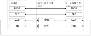
- FIG. 3 is a schematic structural diagram of a system frame according to an embodiment of the present invention.
- FIG. 4 is a flow chart of steps of a data transmission method according to an embodiment of the present invention.
- FIG. 5 is a flowchart of another step of a data transmission method according to an embodiment of the present invention.
- FIG. 6 is a schematic diagram of a configuration of a control plane protocol stack configured by a first radio access network node according to an embodiment of the present disclosure
- FIG. 7 is a schematic diagram of a configuration of a user plane protocol stack configured by a first radio access network node according to an embodiment of the present disclosure
- FIG. 8 is a flowchart of a step of a first radio access network node accessing a target terminal to a second radio access network node according to an embodiment of the present invention
- FIG. 9 is a flowchart of another step of a first radio access network node accessing a target terminal to a second radio access network node according to an embodiment of the present invention.
- FIG. 10 is a flowchart of another step of a data transmission method according to an embodiment of the present invention.
- FIG. 11 is a schematic diagram of a configuration of a user plane protocol stack configured by a second radio access network node according to an embodiment of the present disclosure
- FIG. 12 is a schematic diagram of a configuration of a control plane protocol stack configured by a second radio access network node according to an embodiment of the present disclosure
- FIG. 13 is a schematic diagram of another configuration of a control plane protocol stack configured by a second radio access network node according to an embodiment of the present disclosure
- FIG. 14 is a flowchart of another step of a first radio access network node accessing a target terminal to a second radio access network node according to an embodiment of the present invention
- FIG. 15 is a flowchart of another step of a data transmission method according to an embodiment of the present invention.
- FIG. 16 is a flowchart of another step of a data transmission method according to an embodiment of the present invention.
- FIG. 17 is a flowchart of a step of a data transmission method according to an embodiment of the present invention.
- FIG. 18 is a flowchart of another step of a data transmission method according to an embodiment of the present invention.
- FIG. 19 is a flowchart of another step of a data transmission method according to an embodiment of the present invention.
- FIG. 20 is a flowchart of another step of a data transmission method according to an embodiment of the present invention.
- FIG. 21 is a flowchart of another step of a data transmission method according to an embodiment of the present invention.
- FIG. 22 is a flowchart of a step of accessing a target terminal to a second radio access network node according to an embodiment of the present invention
- FIG. 23 is a flowchart of another step of a data transmission method according to an embodiment of the present invention.
- FIG. 24 is a flowchart of another step of a data transmission method according to an embodiment of the present invention.
- FIG. 25 is a schematic structural diagram of a first radio access network node according to an embodiment of the present disclosure.
- FIG. 26 is a schematic diagram of another structure of a first radio access network node according to an embodiment of the present invention.
- FIG. 27 is a schematic structural diagram of the first radio access network node capable of accessing the target terminal based on a contention-based random access procedure to the first radio access network node according to an embodiment of the present disclosure
- FIG. 28 is a schematic structural diagram of the first radio access network node capable of accessing the target terminal to the second radio access network node according to a non-contention random access procedure according to an embodiment of the present invention.
- FIG. 29 is another schematic structural diagram of a first radio access network node according to an embodiment of the present invention.
- FIG. 30 is a schematic structural diagram of the first radio access network node capable of accessing the target terminal based on a contention-based random access procedure to the first radio access network node according to an embodiment of the present disclosure
- FIG. 31 is a schematic structural diagram of another first radio access network node according to an embodiment of the present disclosure.
- FIG. 32 is another schematic structural diagram of a first radio access network node according to an embodiment of the present disclosure.
- FIG. 33 is a schematic structural diagram of a second radio access network node according to an embodiment of the present disclosure.
- FIG. 34 is a schematic structural diagram of another second radio access network node according to an embodiment of the present disclosure.
- FIG. 35 is a schematic structural diagram of the second radio access network node capable of accessing the target terminal based on a contention-based random access procedure to the second radio access network node according to an embodiment of the present disclosure
- FIG. 36 is a schematic structural diagram of the second radio access network node capable of accessing the target terminal to the second radio access network node according to a non-contention random access procedure according to an embodiment of the present invention.
- FIG. 37 is another schematic structural diagram of a second radio access network node according to an embodiment of the present invention.
- FIG. 38 is a schematic structural diagram of the second radio access network node capable of accessing the target terminal based on a contention-based random access procedure to the second radio access network node according to an embodiment of the present disclosure
- 39 is another schematic structural diagram of a second radio access network node according to an embodiment of the present invention.
- 40 is another schematic structural diagram of a second radio access network node according to an embodiment of the present invention.
- FIG. 41 is another schematic structural diagram of a first radio access network node according to an embodiment of the present invention.
- FIG. 42 is another schematic structural diagram of a second radio access network node according to an embodiment of the present invention.
- FIG. 3 For the structure of the system framework that can implement the data transmission method provided by the embodiment of the present invention, please refer to FIG. 3;
- the system architecture includes a first radio access network node 301 and a second radio access network node 302, and an interface exists between the first radio access network node 301 and the second radio access network node 302.
- the interface can be carried by a carrier such as an optical fiber or a wireless device, and is not limited.
- the first radio access network node 301 and the second radio access network node 302 may be independent radio access network nodes or distributed radio access network nodes, each having part or all of a radio protocol stack. Function, with an interface between them for transmitting information, which can be a wired interface or a wireless interface;
- the first radio access network node 301 may be a base station of an LTE base station or other radio access technologies such as millimeter wave, Universal Mobile Telecommunications System (UMTS);
- UMTS Universal Mobile Telecommunications System
- the first radio access network node 301 may also be an evolved base station combining a radio network controller (RNC) and a Node B (Node B);
- RNC radio network controller
- Node B Node B
- the second radio access network node 302 may be an LTE base station or other radio access access base station such as millimeter wave, UMTS, or an evolved base station.
- the first radio access network node 301 may also be a baseband unit (BBU) pool in a cloud radio access network (C-RAN) architecture, and the second radio access network
- the node 302 can also be a remote radio head (RRH) in the C-RAN architecture.
- BBU baseband unit
- RRH remote radio head
- the first radio access network node 301 may also be a centralized processing network element in a RANAA (radio access network as a service) architecture, and the second radio access network node 302 may also be a distributed processing network element in the RANaaS architecture.
- RANAA radio access network as a service
- the first radio access network node 301 may provide wireless coverage or not provide wireless coverage. For example, if the first radio access network node 301 provides wireless coverage, the first radio access network node 301 has radio frequency ( An RF (radio frequency) system, if the first radio access network node 301 does not provide radio coverage, the first radio access network node 301 does not have an RF system;
- radio frequency An RF (radio frequency) system
- the second radio access network node 302 generally provides wireless coverage, that is, the second radio access network node 302 has an RF system;
- the radio spectrum used by the first radio access network node 301 and the second radio access network node 302 may be the same frequency band or the same frequency, or may be different frequency bands or different frequencies;
- Each of the second radio access network nodes 302 may use the same frequency band or the same frequency (frequency), or may be different frequency bands or different frequencies;
- the system framework structure shown in FIG. 3 may also be composed of a plurality of first radio access network nodes 301 and a plurality of second radio access network nodes 302;
- the plurality of second radio access network nodes 302 may also be connected to the second radio access network node 302 central control network element, and then connected to the first radio access network node 301;
- the first radio access network node 301 and the second radio access network node 302 are different components of the same distributed base station, where the first radio access network node 301 includes a radio resource control layer of a radio interface protocol.
- the RRC, the packet data convergence layer PDCP optionally, further includes one or more of the following radio interface protocol layers: a radio link control layer RLC, a medium access control layer MAC, a physical layer PHY, and the second radio interface
- the access node 302 includes a radio frequency unit, and optionally includes one or more of the following radio interface protocol layers: a radio link control layer RLC, a medium access control layer MAC, a physical layer PHY, and a baseband processing unit;
- the distributed base station may include a first radio access network node 301 and a plurality of second radio access network nodes 302.
- the first radio access network node 301 and the second radio access network node 302 are two independent base stations, respectively having all protocol layers of the radio interface protocol layer: radio resource control layer RRC, packet data convergence Layer PDCP, Radio Link Control Layer RLC, Medium Access Control Layer MAC, Physical layer PHY, and RF unit.
- radio resource control layer RRC radio resource control layer
- PDCP packet data convergence Layer
- Radio Link Control Layer RLC Radio Link Control Layer
- Medium Access Control Layer MAC Medium Access Control Layer MAC
- Physical layer PHY Physical layer
- An embodiment of the present invention is described by taking one of the first radio access network node 301 and one of the second radio access network nodes 302 shown in FIG. 3 as an example.
- the first radio access network node determines a target radio access network node to which the media access control layer serving the target terminal belongs, and if the target radio access network node is the first radio access network node, And proceeding to step 402, if the target radio access network node is the second radio access network node, proceeding to step 403, if the target radio access network node is the first radio access network node, and The second radio access network node proceeds to step 404;
- the target radio access network node is the first radio access network node, or a second radio access network node, or the first radio access network node and the second radio access network node;
- the specific number of the target terminals is not limited in this embodiment, that is, the target terminals may be one or more.
- the target radio access network nodes to which the media access control layer serving the target terminal belongs may be different or the same.
- the same target radio access network node may also be used for all terminals within the coverage of the second access network node; when the first radio access network node also has radio coverage, for the coverage of the first radio access network node All terminals use the same target radio access network node.
- the first radio access network node may determine that the target terminal initially accesses the network establishment service or the target terminal establishes or modifies a service bearer in a radio resource control (RRC) connection state.
- the target radio access network node determines the target radio access network node according to a radio condition or when the target terminal moves.
- the first radio access network node may indicate the target radio access network node in a system information broadcast, thereby covering the second radio access network node and/or the first radio access network node. All terminals use a common target radio access network node.
- the determination method of the radio access network node is described as an example, and is not limited:
- the first radio access network node may determine a target radio access for serving UE1
- the network node is the second radio access network node
- the target radio access network node serving the UE2 is the first access network node, thereby reducing the first radio access network node and the second radio access
- the first radio access network node determines a target radio access network serving UE2.
- the node is the first radio access network node
- the target radio access network node serving the UE1 is the second radio access network node, thereby reducing the first radio access network node and the second radio access.
- the first radio access network node may determine that the target radio access network node serving the UE 2 is the first radio access network node, and the target for the UE1 is served.
- the radio access network node is the second radio access network node, thereby reducing the impact of the capacity of the interface between the first radio access network node and the second radio access network node on the large bandwidth service.
- the first radio access network node may determine to perform UE1.
- the target radio access network node of the service is the first radio access network node
- the target radio access network node serving the UE2 is the second radio access network node, because the first radio access network node is more Facilitating obtaining wireless condition information of multiple cells, so that the first radio access network node can perform multi-cell interference control or load balancing;
- the first radio access network node determines a target wireless service for the target terminal.
- the access network node is the first radio access network node and the second radio access network node, wherein the first radio access network node and the second radio access network node cooperate to serve the
- the target terminal enables the target radio access network node to take into account both delay and radio conditions
- the manner of the specific collaborative service is not limited in this embodiment;
- the first radio access network node and the second radio access network node may determine the location based on a hybrid automatic retransmission request (RTT) round trip time (RTT) Determining whether the interface delay between the first radio access network node and the second radio access network node meets the service delay requirement, thereby determining to use the first radio access network node to serve the target terminal Whether the second radio access network node is used to serve the target terminal, or the first radio access network node and the second radio access network node cooperate to serve the target terminal, the first The interface between the radio access network node and the second radio access network node may be referred to as a backhaul (or fronthaul).
- RTT hybrid automatic retransmission request
- RTT round trip time
- the first radio access network node specifically determines whether the target radio access network node is not limited, as long as the first radio access network node can determine to serve the target terminal.
- the target radio access network node can be.
- the target radio access network node specifically defines how to serve the target terminal, as long as the service of the target radio terminal by the target radio access network node can effectively guarantee the first radio access.
- the transmission of data between the network node and the second radio access network node and the target terminal may be performed.
- the first radio access network node determines first allocation information.
- the first allocation information is used to indicate that the first radio access network node configures a first media access control layer function for serving the target terminal;
- the first radio access network node can configure, according to the first allocation information, a first media access control layer function served by the target terminal, so that the first radio access network node The target terminal can be serviced according to the configured first medium access control layer function.
- the first radio access network node instructs the second radio access network node to determine second allocation information.
- the second allocation information is used to indicate that the second radio access network node configures a second medium access control layer function for serving the target terminal, so that the second radio access network node can Serving the target terminal according to the configured second medium access control layer function.
- the first radio access network node determines third allocation information and fourth allocation information.
- the third allocation information is used to indicate that the first radio access network node configures a third medium access control layer function for serving the target terminal
- the fourth allocation information is used to indicate the The second radio access network node configures a fourth medium access control layer function for serving the target terminal.
- the first radio access network node can configure the third medium access control layer function according to the determined third allocation information, where the second radio access network node can be determined according to the determined
- the fourth allocation information configures the fourth media access layer control function.
- the first medium access control layer function, the second medium access control layer function, the third medium access control layer function, and the fourth medium access control layer function at least include One or more of the following:
- step 402 After performing step 402, or step 403, or step 404, proceed to step 405;
- the preset condition is: the service data of the target terminal is re-allocated, or added, or deleted, or the quality of service (QoS) of the service carried by the control plane signaling radio bearer SRB or the user plane data radio bearer DRB is modified. , a quality of service parameter, or a change in the wireless condition of the target terminal, for example, because the target terminal moves to cause a change in the wireless environment in which it is located;
- QoS quality of service
- the first radio access network node determines that the target terminal meets the preset condition, triggering the step of the first radio access network node to re-determine the target radio access network node, that is, returning to step 401 .
- the first radio access network node may determine, according to the service data and/or the radio condition of the target terminal, whether the target terminal satisfies the preset condition, or may be configured by the second radio access network. Determining, by the node according to the service data and/or the wireless condition of the target terminal, whether the target terminal meets the preset condition, and notifying the first radio access network node of the determined result, or by the first The radio access network node and the second radio access network node negotiate to determine, for example, the first The radio access network node determines whether the service data of the target terminal changes, and the second radio access network node determines whether the radio condition of the target terminal changes, and if any one of the changes changes, the process returns to step 401. .
- the media access control MAC layer of the first radio access network node or the second radio access network node is mainly for MAC control of a corresponding target terminal, such as a HARQ entity and The target terminal dedicated resource part, since the first radio access network node and the second radio access network node also need to manage other terminals, therefore, from the perspective of the cell, the first radio access network node and the second The radio access network nodes each include a MAC layer, including at least a common part of the MAC layer, such as a random access procedure control common part, and a scheduling/priority processing common part, because this part of the functions involves the control of multiple terminals.
- the data transmission method shown in this embodiment effectively improves system performance, reduces performance requirements and costs for interface bearers between the first radio access network node and the second radio access network node, for example, reduces the interface.
- the bandwidth and delay requirements can meet the service quality (QoS) requirements of the service and improve the system resource utilization efficiency.
- QoS service quality
- the following describes the method for implementing data transmission when the first radio access network node determines that the target radio access network node is the first radio access network node according to the embodiment shown in FIG. 5 . :
- the target terminal uses a low frequency, such as a 2.6 GHz, a small bandwidth, such as a 20 MHz bandwidth, as an example, and the first radio access network node and the second radio access network node both exist with the target terminal.
- a low frequency such as a 2.6 GHz
- a small bandwidth such as a 20 MHz bandwidth
- the first radio access network node determines that the target radio access network node to which the media access control layer serving the target terminal belongs is the first radio access network node.
- the first radio access network node may determine a target radio access network node serving the target terminal.
- the first radio access network node is configured to reduce the impact of the capacity of the interface between the first radio access network node and the second radio access network node on the large bandwidth service.
- the node is not limited to the first radio access network node, for example, the first radio access network node may determine the target radio access network node according to service data of the target terminal and radio conditions, or The target radio access network node may be determined by the second radio access network according to the service data of the target terminal and the radio condition, and the second radio access network node determines the target radio that has been determined.
- the access network node notifies the first radio access network node, or the first radio access network node and the second radio access network node jointly negotiate according to the service data of the target terminal and the radio condition Determining the target radio access network node.
- the first radio access network node determines first allocation information.
- the specific manner in which the first radio access network node and the second radio access network node provide radio coverage for the target terminal is not limited.
- the first radio connection may be Both the network access node and the second radio access network node provide wireless coverage, for example, the first radio access network node may not provide wireless coverage, and the second radio access network provides wireless coverage;
- the first radio access network node does not provide radio coverage
- the second radio access network provides radio coverage as an example for example:
- the media access control layer serving the target terminal belongs to the first radio access network node, that is, the RRC control plane function provided by the wireless connection of the first radio access network node,
- the case where the target terminal uses the user plane function provided by the wireless connection of the second radio access network node is taken as an example for description;
- the configuration of the control plane protocol stack configured by the first radio access network node is as shown in FIG. 6, and the configuration of the user plane protocol stack configured by the first radio access network node is as shown in FIG. 7;
- the MAC layers of the first radio access network node and the second radio access network node shown in FIG. 7 are indicated by broken lines to indicate that the first wireless can be used according to the configuration of the target terminal's service data and wireless conditions.
- the first radio access network node may generate a first allocation. information
- the first allocation information refers to a MAC layer function division of the first radio access network node, And the first allocation information is sent to the second radio access network node via an interface between the first radio access network node and the second radio access network node.
- the first radio access network node configures the first media access control layer function according to the first allocation information.
- the first radio access network node may configure the first media access control layer function according to the first allocation information, where the first media access control layer function is the first radio access network node
- the media access control layer is used to perform all functions of the target terminal
- the first medium access control layer function includes at least one or more of the following:
- the first radio access network node sends the first allocation information to the second radio access network node.
- the first allocation information determines that the target radio access network node serving the target terminal is the first radio access network node.
- the second radio access network node may also send a radio resource control connection reconfiguration (RRCConnectionReconguration) message to the target terminal, where the radio resource control connection reconfiguration message is used to make the target terminal Determining that the media access control layer of the target terminal corresponds to the media access control layer of the first radio access network node, so that the target terminal determines that the first radio access network node is used for Target radio access network node.
- RRCConnectionReconguration radio resource control connection reconfiguration
- the first radio access network node performs data transmission with the target terminal according to the configured first medium access control layer function.
- the second radio access network node carries the RRC letter between the second radio access network node and the target terminal by using a control plane signaling radio bearer SRB.
- the MAC layer of the first radio access network node, the MAC PDU including the RRC downlink signaling is encapsulated by the interface message of the first radio access network node and the second radio access network node, and then sent to The second radio access network node, the second radio access network node directly withdraws the MAC PDU in the interface message to the PHY layer or the MAC layer of the second radio access network node, where the second The MAC layer of the radio access network node does not further process the MAC PDU, and is further processed by the physical layer of the second radio access network node and then sent to the target terminal via the radio interface between the second radio access network node and the target terminal.
- the peer RRC protocol layer is still in the first radio access network node, and the target terminal needs to send the uplink RRC message first.
- the second radio access network node passes the MAC SDU including the uplink RRC message through the first radio access network node and the second radio access network node
- the interface message is packetized and sent to the first radio access network node, where the first radio access network node extracts the MAC SDU in the interface message and submits it to the RLC layer of the first radio access network node, and then passes each
- the layer protocol is further processed and then submitted to the RRC layer of the first radio access network node.
- the MAC layer of the first radio access network node allocates radio resources for downlink data transmission of the target terminal; and media access control layer of the first radio access network node Generating, by the MAC, a medium access control layer protocol data unit MAC PDU according to the service data of the target terminal; the hybrid automatic repeat request (HARQ entity) of the first radio access network controls HARQ transmission for the target terminal MAC PDU,
- HARQ entity hybrid automatic repeat request
- the HARQ process and the physical layer processing are performed by the second radio access network node, and the MAC layer function of the second radio access network node is disabled, and is transparent to the target terminal.
- the MAC layer of the first radio access network node allocates radio resources for uplink data transmission of the target terminal; the target terminal according to the first allocation information, that is, the The target terminal will end the target according to the user plane protocol stack configuration as shown in FIG.
- All or part of the uplink data of the terminal is sent from the target terminal to the second radio access network node, and the second radio access network node receives the uplink data of the target terminal, and after being successfully decoded by the physical layer, the data is sent to the a MAC layer of the first radio access network node, the MAC layer of the second radio access network node is transparent to the target terminal, and is further forwarded by the MAC layer of the second radio access network node to an upper protocol layer Process it.
- the MAC PDU is transmitted between the interfaces of the first radio access network node and the second access network node, and the MAC PDU may be encapsulated and transmitted according to the data format specified by the interface protocol.
- the transmission is performed by the GTP-U protocol or the IP protocol or the CPRI protocol, which is not limited herein.
- all or part of the downlink data of the user plane data radio bearer DRB is first sent from the first radio access network node to the second radio access network node, or may be started through the PDCP layer or the RLC layer, thereby starting from the first wireless
- the downlink data sent by the access network node to the second radio access network node may also be a PDCP protocol data unit (PDU) or an RLC PDU.
- all or part of the uplink data of the user plane data radio bearer DRB received by the second radio access network node is sent to the first radio access network node, and may also start through the PDCP layer or the RLC layer, thereby
- the uplink data sent by the access network node to the first radio access network node may also be a PDCP protocol data unit (PDU) or an RLC PDU.
- PDU PDCP protocol data unit
- the second radio access network node provides wireless coverage as an example, and the first radio access network node and the second radio access network node may simultaneously or time-sharing the target.
- the terminal performs wireless communication;
- the first radio access network node generates downlink data according to the configured first medium access control layer function, and the downlink data may be further processed by the second radio access network node and sent to Transmitting, by the target terminal, the first radio access network node, the downlink data to the target terminal;
- the uplink data of the target terminal may be processed by the second radio access network node and sent to the first radio access network node, or the target terminal may directly send uplink data to the first radio interface. And the first radio access network node processes the uplink data according to the first media access control layer function.
- the first radio access network node performs data transmission with the target terminal through the second radio access network node
- the second is the a radio access network node directly performs data transmission with the target terminal
- the first radio access network node performs data transmission with the target terminal by using the second radio access network node, before the data transmission, the first wireless The access network node needs to access the target terminal to the second radio access network node.
- the target terminal accesses the second radio access network node in two ways, and the other is that the target terminal accesses the second radio access network node according to a contention random access procedure. Another type is that the target terminal accesses the second radio access network node based on a non-contention random access procedure;
- the target terminal accesses the second radio access network node based on a contention random access procedure as shown in FIG. 8:
- the first radio access network node receives a first request message sent by the second radio access network node.
- the first request message is used to request to access the target terminal to the second radio access network node;
- the first request message is a random access preamble selected by the target terminal, and the target terminal sends the first request message to the location according to the selected random access time-frequency domain resource.
- the first radio access network node and the second radio access network node transmit information through an interface
- the interface may be an X2 interface, or a CPRI interface, or a radio interface or other interface.
- the embodiment of the present invention does not limit the specific form of the interface.
- the first request message is further used to request the first radio access network node to generate a random access response message (RAR) at the MAC layer;
- RAR random access response message
- the second radio access network node further includes a random access preamble index (RAPID) information in the first request message;
- RAPID random access preamble index
- the first request message further includes a physical random access channel (PRACH) time-frequency domain.
- PRACH physical random access channel
- the function of the first request message is:
- the first radio access network node calculates an RA-RNTI
- the first radio access network node calculates an uplink TA, where the uplink TA is an uplink TA for the target terminal to the second radio access network node; the TA represents a distance between the target terminal and an antenna port;
- Timing Advance which means timing advance
- the purpose of timing advance is to compensate for the delay of radio wave transmission.
- the fundamental purpose is to improve the channel codec efficiency.
- the first radio access network node allocates an uplink grant (UL grant);
- the RRC layer of the first radio access network node allocates a temporary cell radio network temporary identifier (TC-RNTI).
- TC-RNTI temporary cell radio network temporary identifier
- the second radio access network node calculates an RA-RNTI and an uplink TA, and the second radio access network node calculates the RA-RNTI and The result of the uplink TA is sent to the first radio access network node.
- the first response message that is generated by the first radio access network node according to the first request message.
- the first response message includes the random access response message (RAR) and the RA-RNTI.
- the first radio access network node sends a first response message that is generated according to the first request message to the second radio access network node.
- the second radio access network node After receiving the first response message, the second radio access network node processes the first response message and generates a processed first response message;
- the RA-RNTI information is indicated by the physical downlink control channel PDCCH, and the RAR message is indicated by the physical downlink shared channel PDSCH.
- the format of the first response message sent by the first radio access network node to the second radio access network node may be different from the manner that the second radio access network node sends to the target terminal.
- the first response message after processing.
- the first radio access network node may send the UL grant and the TC-RNTI to the second radio access network node, and the second radio access network node generates a first response message and sends the message to the target terminal. .
- the processed first response message is configured to enable the target terminal to generate a second request message for triggering the first radio access network to perform contention resolution, and the target terminal sends the second request message to The second radio access network node;
- the second radio access network node After receiving the second request message, the second radio access network node processes the second request message and generates a processed second request message;
- the second radio access network node sends the processed second request message to the first radio access network node.
- the second request message includes an identifier S-TMSI or a random number of the target terminal, or a cell radio network temporary identifier (C-RNTI).
- the second request message further includes a radio resource control connection.
- the second radio access network node processes the second request message, so that the processed second request message includes an identifier S-TMSI or a random number or a C-RNTI of the target terminal, optionally,
- the processed second request message may further include an RRCConnectionRequest or RRCConnectionReestablishmentRequest message, wherein the message sent by the second radio access network node to the first radio access network node uses the second radio access network node and The message of the interface between the first radio access network nodes.
- the first radio access network node receives the processed second request message.
- the first radio access network node performs contention resolution according to the processed second request message to generate a contention resolution message.
- the first radio access network node sends the generated second response message to the second radio access network node.
- the second response message is used to indicate the contention resolution message
- the first radio access network node uses the C-RNTI as a contention resolution identifier.
- the second response message may further include a radio resource control connection establishment (RRCConnectionSetup) message or a radio resource control connection re-establishment ( RRCConnectionReestablishment) message, etc.
- the second radio access network node After receiving the second response message, the second radio access network node processes the second response message and generates a processed second response message;
- the second radio access network node sends the received second response message from the first radio access network node to the target terminal after being processed by the physical layer;
- the second radio access network node uses a downlink grant (DL assignment) or an uplink grant (UL grant) on a physical downlink control channel (PDCCH) scrambled by C-RNTI or TC-RNTI. ) indicating the message to the target terminal.
- DL assignment downlink grant
- UL grant uplink grant
- PDCCH physical downlink control channel
- the second response message sent by the first radio access network node to the second radio access network node is used by the second radio access network node and the first radio access network node.
- the message of the inter-interface may be different from the format of the processed second response message sent by the second radio access network node to the target terminal, for example, the first radio access network node sends the
- the second response message of the second radio access network node is a MAC PDU including the second response message that is encapsulated by the interface message.
- the target terminal accesses the second radio access network node according to the processed second response message or acquires uplink synchronization with the second radio access network node.
- the first radio access network node directly performs data transmission with the target terminal, the first radio access network node needs to directly access the target terminal to the first radio interface.
- the process of the ingress of the node and the process of obtaining the uplink synchronization between the target terminal and the first radio access network node is not described here, but only the uplink timing in step 802.
- the advance TA is a TA between the target terminal and the first radio access network node.
- the first radio access network node allocates a dedicated physical random access channel PRACH resource and a third request message to the target terminal.
- the third request message is a random access preamble selected by the target terminal, so that the target terminal can be configured according to the dedicated physical random allocated by the first radio access network node.
- the access channel PRACH resource sends the third request message;
- the first radio access network node sends the dedicated physical random access channel PRACH resource and the third request message to the second radio access network node.
- the second access network node Transmitting, by the second access network node, the dedicated physical random access channel PRACH resource and the third request message (that is, the information of the random access preamble) to the target terminal, for example, indicating the target by using a PDCCH terminal;
- a third request message that is, a random access preamble, by using the dedicated physical random access channel (PRACH) resource;
- the target terminal may be allocated a dedicated physical random access channel PRACH resource and a third request message by the second radio access network node;
- the random access preamble shown in FIG. 9 is allocated to the target terminal by the first radio access network node or the second radio access network node.
- the first radio access network node receives the third request message.
- the first radio access network node generates a third response message according to the third request message.
- the specific process of the third radio access network node generating the third response message according to the third request message as shown in FIG. 8 , the first radio access network node generates the location according to the first request message.
- the specific process of the first response message is not described in detail in this embodiment.
- the first radio access network node sends the third response message to the second wireless Access network node.
- the second radio access network node processes the third response message after receiving the third response message to generate a processed third response message, and the second access network node performs the processing Sending a third response message to the target terminal, so that the target terminal accesses the second radio access network node or acquires with the second radio access network node according to the processed third response message.
- the uplink timing advance TA is a TA between the target terminal and the first radio access network node.
- the first radio access network node generates downlink data and downlink control information according to the first media access control layer function
- the MAC layer and the PHY layer of the first radio access network node cooperate to generate the downlink data and the downlink control information
- the downlink data includes a downlink medium access control service data unit MAC SDU, and/or a downlink medium access control control unit MAC CE;
- the downlink control information includes downlink hybrid automatic repeat request HARQ information and downlink authorization information;
- the second radio access network node sends the downlink data and the downlink control information to the target terminal.
- the second radio access network node sends the downlink data and the downlink control information by using different physical channels.
- the second radio access network node sends the downlink control information by using a PDCCH. Giving the target terminal;
- the second radio access network node sends the downlink data to the target terminal by using a PDSCH.
- the target terminal After receiving the downlink control information, the target terminal receives the downlink data according to the indication of the downlink control information.
- the downlink control information generated by the first radio access network node according to the configured first medium access control layer function may be downlink grant information (DL assignment) information;
- the downlink grant information includes information such as a set of NDI, TB size, HARQ process identifier, and the like generated for each transport block.
- the downlink authorization information may be hybrid automatic repeat request (HARQ information), and the HARQ information includes a new data indicator (NDI, New Data Indicator), a transport block (TB), a HARQ process ID, and the like. information;
- NDI new data indicator
- TB transport block
- HARQ process ID HARQ process ID
- the interface of the ingress node indicates the MAC layer of the first radio access network node
- the MAC layer of the first radio access network node decides to schedule a new transmission or retransmit the HARQ redundancy version (RV), and the first radio access network node sends the new downlink grant information to the second radio. Accessing the network node to cause the second radio access network node to resend the new downlink grant information to the target terminal.
- RV HARQ redundancy version
- the first radio access network node generates a downlink MAC CE according to the configured first medium access control layer function
- the second radio access network node sends the downlink MAC CE to the target terminal.
- the MAC CE includes at least one or more of the following: a TA command, a secondary carrier (SCell) activation/deactivation, and a discontinuous reception command (DRX cmd).
- the first radio access network node generates uplink control information according to the first media access control layer function
- the second radio access network node sends the uplink control information to the target terminal by using a PDCCH
- the uplink control information includes uplink hybrid automatic repeat request HARQ information and uplink authorization information;
- the media access control layer of the first radio access network node receives uplink data
- the uplink data is sent by the target terminal to the second radio access network node;
- the uplink data is generated by the target terminal according to the uplink control information, and the uplink data includes a MAC SDU, and/or a control unit MAC CE of an uplink medium access control;
- the media access control layer of the first radio access network node processes the uplink data according to the first media access control layer function.
- the uplink control information generated by the first radio access network node according to the configured first medium access control layer function may be uplink grant (UL grant) information;
- the uplink authorization information may be hybrid automatic repeat request (HARQ information), and the HARQ information includes information such as a new data indicator (NDI, New Data Indicator), a transport block (TB), a redundancy version, and the like;
- HARQ information includes information such as a new data indicator (NDI, New Data Indicator), a transport block (TB), a redundancy version, and the like;
- the target terminal sends a data packet to the second radio access network node on a physical uplink shared channel (PUSCH);
- PUSCH physical uplink shared channel
- the MAC PDU is sent to the first radio access network node by using an interface between the second radio access network node and the first radio access network node.
- the MAC layer of the first radio access network node determines to schedule a new transmission or retransmit a HARQ redundancy version (RV, redundancy version), and the first radio access network node sends the new uplink grant information to the first And a second radio access network node, so that the second radio access network node can send new uplink grant information to the target terminal.
- RV redundancy version
- the target terminal generates an uplink MAC CE
- the second radio access network node sends the uplink MAC CE to the first radio access network node by using an interface between the first radio access network node and the second radio access network node.
- the uplink MAC CE includes at least one or more of the following: a buffer status report (BSR), a power headroom report (PHR), and the like.
- BSR buffer status report
- PHR power headroom report
- the target terminal sends uplink channel state information (CSI) to the second radio access network node;
- CSI uplink channel state information
- the second radio access network node sends the uplink CSI to the first radio access network node through an interface between the first radio access network node and the second radio access network node;
- the first radio access network node performs scheduling decision according to the uplink CSI, for example, determines a modulation coding scheme (MCS) used for scheduling, and the like.
- MCS modulation coding scheme
- the uplink CSI includes at least one or more of the following information:
- CQI Channel quality indication
- precoding matrix index precoding matrix index
- rank indication precoding type indication
- PTI precoding type Indication
- the target terminal sends uplink SR information to the second radio access network node
- the second radio access network node sends uplink SR information to the first radio access network node through an interface between the first radio access network node and the second radio access network node;
- the first radio access network node allocates an uplink grant to the target terminal according to the uplink SR information.
- the uplink data and the downlink data between the first radio access network node and the target terminal are sent by using the second radio access network node, and of course, the target terminal may also be used.
- the first radio access network node When the first radio access network node is accessed and synchronized with the first radio access network node, the first radio access network node directly implements uplink data and downlink with the target terminal. The transmission of data will not be described in detail.
- the first radio access network node may determine, according to the service data and the radio condition of the target terminal, a target radio access network node to which the media access control layer serving the target terminal belongs. a radio access network node, such that the MAC layer of the first radio access network node provides a service for the target terminal, that is, the first radio access network node generates first allocation information, and according to the first Allocating information configures a first medium access control layer function, and the first medium access control layer function is used by the medium access control layer of the first radio access network node to serve the target terminal
- the target radio access network terminal can be flexibly determined according to the service data and the radio condition of the target terminal, so that the flexible deployment can be performed according to the existing network service, and the first radio access network node is reduced.
- the performance requirements and costs of the interface between the nodes of the second radio access network for example, reduce the bandwidth and delay requirements of the interface, and can satisfy the service quality of the service (QoS) , quality of the service (QoS) ,
- the following describes the method for implementing data transmission when the first radio access network node determines that the target radio access network node is the second radio access network node according to the embodiment shown in FIG. 10:
- the first radio access network node determines that the target radio access network node to which the media access control layer serving the target terminal belongs is the second radio access network node;
- the first radio access network node specifically determines that the target radio access network node is the second radio access network node, and may be, for example, the first radio access network. Determining, by the node, the target radio access network node according to the service data of the target terminal and the radio condition, or determining, by the second radio access network, the target radio according to the service data of the target terminal and the radio condition Accessing a network node, and the second radio access network node notifying the determined target radio access network node to the first radio access network node, or by the first radio access network node And determining, by the second radio access network node, the target radio access network node according to the service data of the target terminal and the radio condition negotiation.
- the target terminal is located at a cell center provided by a second radio access network node, and the first radio access network node determines that the target radio access network node serving the target terminal is the
- the two radio access network nodes are generally not interfered with by other cell radio conditions like the terminal at the cell edge. .
- the embodiment may be specifically applied to provide wireless coverage by the first radio access network node and the second radio access network node, or only the second radio access network node provides radio coverage, and the target a case where the terminal only has a wireless connection with the second radio access network node;
- the first radio access network node instructs the second radio access network node to determine second allocation information.
- the second allocation information is used to indicate that the second radio access network node configures a second media access control layer function for serving the target terminal;
- the first radio access network node specifically indicates that the second radio access network node determines the second allocation information is not limited, as long as the second radio access network node can be located in the The second allocation information may be determined under the control of the first radio access network node.
- the first radio access network node can be indicated in a semi-static manner
- the first radio access network node generates configuration information
- the second radio access network layer is configured to configure the second medium access control layer function for the target terminal according to the second allocation information, where the second medium access control layer function is the second Wireless access
- the media access control layer of the network node is used to perform all functions of the target terminal.
- the second radio access network node always generates the second allocation information according to the configuration information after receiving the configuration information;
- the first radio access network node may determine the second allocation information by dynamically indicating the second radio access network node
- the first radio access network node dynamically instructs the second radio access network node to generate the second allocation information according to the service data and the radio condition of the target terminal.
- the first radio access network node and the second radio access network node each provide radio coverage, or only the second radio access network node provides radio coverage, and the target terminal only has
- the case where the second radio access network node has a wireless connection is taken as an example for description;
- the configuration of the user plane protocol stack configured by the second radio access network node according to the second allocation information is as shown in FIG. 11, and the second radio access network node is configured according to the second allocation information.
- the control plane protocol stack configuration is shown in Figure 12;
- the first radio access network node specifically instructs the second radio access network node to determine the second allocation information.
- the first radio access network node sends configuration information, where the configuration information is MAC layer function allocation information determined by the first radio access network node, and the second radio access network node and the second radio interface
- the interface message of the network access node is packaged and sent to the second radio access network node; the specific process of the second radio access network node determining the second allocation information according to the configuration information is: the second
- the radio access network node determines, according to the configuration information, all functions used by the media access control layer of the second radio access network node to serve the target terminal.
- the second medium access control layer function includes at least one or more of the following:
- control plane protocol stack configured by the second radio access network node according to the second allocation information is also shown in FIG. 11;
- the second radio access network node carries RRC signaling between the second radio access network node and the target terminal by using an SRB or a DRB;
- the SRB and the DRB specifically refer to the first radio access network node and the second radio access network
- the processing of the control plane protocol stack for example, the SRB of the first radio access network node includes the PDCP layer of the first radio access network node, and the RRC message of the first radio access network node passes the first
- the PDCP PDU is packetized by the interface information of the first radio access network node and the second radio access network node, and then sent to the second radio access network node.
- the second radio access network node directly sends the PDCP PDU in the interface message to the RLC layer, and is processed by the RLC layer and further submitted to the lower protocol layer.
- the peer RRC protocol layer is still in the first radio access network node.
- the other processing manner of the control plane protocol stack includes, for example, that the SRB of the first radio access network node includes an RLC layer of the first radio access network node, and the first radio access network node passes the first The RLC PDUs of the radio access network node and the second radio access network node interface message including the RRC downlink signaling are sent to the second radio access network node, and details are not described herein.
- All downlink data of the user plane data radio bearer DRB is first sent from the first radio access network node to the second radio access network node, and may be through the PDCP of the first radio access network node or the first radio access
- the RLC layer of the network node starts, so that the downlink data sent from the first radio access network node to the second radio access network node may be a PDCP protocol data unit (PDU) or an RLC PDU.
- PDU PDCP protocol data unit
- RLC PDU Radio Link Control
- All uplink data of the user plane DRB is sent from the target terminal to the second radio access network node, and then sent from the second radio access network node to the first radio access network node, and correspondingly,
- the uplink data sent by the second radio access network node to the first radio access network node may be a MAC PDU or a TB.
- the first radio access network node performs data transmission according to the configured second medium access control layer function.
- step 1003 in detail:
- the first radio access network node sends the generated downlink data to the second radio access network node, and the second radio access network node performs the function according to the second medium access control layer.
- the downlink data is processed, and the processed downlink data is sent to the target terminal;
- the uplink data of the target terminal is sent to the second radio access network node, and the second radio access network node processes the uplink data according to the function of the second medium access control layer, and the processed The uplink data is sent to the first radio access network node.
- the downlink data generated by the first radio access network node is sent to the second radio access network node, and the second radio access network node is configured according to the second medium access control layer function.
- the target terminal needs to access the second radio access network node, and the target terminal acquires Synchronization of the second radio access network node;
- the target terminal accesses the second radio access network node in two ways, one is that the target terminal randomly accesses the second radio access network node based on contention, and the other Determining, by the target terminal, the second radio access network node based on non-contention random access;
- the first radio access network node receives a fourth request message sent by the second radio access network node.
- the fourth request message is used to request that the target terminal access the second radio access network node
- the fourth request message is a random access preamble selected by the target terminal, and the target terminal sends the first request message to the location according to the selected random access time-frequency domain resource.
- the first radio access network node and the second radio access network node transmit information through an interface
- the interface may be an X2 interface, or a CPRI interface, or a radio interface or other interface.
- the embodiment of the present invention does not limit the specific form of the interface.
- the fourth request message is further configured to request the first radio access network node to allocate a temporary cell radio network temporary identifier (TC-RNTI).
- TC-RNTI temporary cell radio network temporary identifier
- the first radio access network node generates a fourth response message according to the fourth request message.
- the fourth response message includes an RRC layer allocated TC-RNTI of the first radio access network node.
- the first radio access network node sends the fourth response message to the second radio access network node.
- the manner in which the second radio access network node processes the fourth response message to generate the processed fourth response message may be: the second radio access network node calculates the RA-RNTI, generates a RAR message, and The RAR message includes information such as a random access preamble index RAPID, an uplink timing advance TA, and an uplink grant (UL grant).
- RAPID random access preamble index
- TA uplink timing advance
- UL grant uplink grant
- the network node processes the fifth request message, and sends the generated processed fifth request message to the first radio access network node.
- the first radio access network node receives the processed fifth request message.
- the processed fifth request message includes an S-TMSI or a random number of the target terminal, or a cell radio network temporary identifier (C-RNTI).
- the processed fifth request message further includes a wireless A resource control connection request (RRCConnectionRequest) message or a radio resource control connection reconfiguration (RRCConnectionReestablishmentRequest) request message.
- RRCConnectionRequest wireless A resource control connection request
- RRCConnectionReestablishmentRequest radio resource control connection reconfiguration
- the processed fifth request message may further include an RRCConnectionRequest or RRCConnectionReestablishmentRequest message, wherein the message sent by the second radio access network node to the first radio access network node uses the A message of an interface between the second radio access network node and the first radio access network node.
- the first radio access network node performs a contention solution according to the processed fifth request message. Determine to generate a competition resolution message;
- the first radio access network node uses the C-RNTI as a contention resolution identifier.
- the message may further include a radio resource control connection establishment (RRCConnectionSetup) message or a radio resource control connection re-establishment (RRCConnectionReestablishment) message.
- RRCConnectionSetup radio resource control connection establishment
- RRCConnectionReestablishment radio resource control connection re-establishment
- the first radio access network node sends the contention resolution message to the second radio access network node.
- the second radio access network node generates a fifth response message according to the contention resolution message
- the second radio access network node processes the fifth response message to generate a processed fifth response message, and sends the processed fifth response message to the target terminal, so that the target terminal And determining, according to the processed fifth response message, accessing the second radio access network node or acquiring uplink synchronization with the second radio access network node.
- the second radio access network node indicates to the UE by using a downlink grant (DL assignment) or an uplink grant (UL grant) on a physical downlink control channel (PDCCH) that is scrambled by the C-RNTI.
- DL assignment downlink grant
- UL grant uplink grant
- PDCCH physical downlink control channel
- the target terminal may also access the second radio access network node by means of non-contention based random access.
- non-contention based random access refer to the non-contention based randomization in the existing LTE technology. The access process will not be described here.
- the first radio access network node generates downlink data
- the downlink data may be an RLC PDU or a MAC SDU, or may be a PDCP PDU.
- the media access control layer of the second radio access network node processes the downlink data according to the second media access control layer function to generate processed downlink data
- the processed downlink data may be a MAC PDU
- the second radio access network node Transmitting, by the second radio access network node, the processed downlink data to the target terminal, where the processed downlink data includes a MAC SDU, and/or a control unit MAC of a downlink medium access control CE.
- the downlink control information is directly generated and sent by the second access network node according to the second media access control layer function to the target terminal.
- the second radio access network node generates a downlink MAC PDU according to the configured second medium access control layer function
- the second radio access network node indicates, by using an interface between the first radio access network node and the second radio access network node, that the RLC layer located on the first radio access network node can The size of the generated RLC PDU.
- the second radio access network node may indicate total size information of a plurality of RLC PDUs that may be scheduled by all logical channels, or respectively indicate size information of one or more RLC PDUs that each logical channel may schedule.
- the second radio access network node sends downlink grant information including HARQ information to the target terminal, and the HARQ ACK/NACK feedback of the target terminal is sent to the second radio access network node.
- the HARQ process according to the prior art can be used;
- the second radio access network node generates a downlink MAC CE to send to the UE, which is the same as the transmission mode of the existing LTE technology downlink MAC CE.
- the processed uplink data is generated by the media access control layer of the second radio access network node according to the second media access control layer function, and the uplink data is processed by the second data access control layer.
- the target terminal is sent to the second radio access network node, and the uplink data includes a MAC SDU, and/or a control unit MAC CE of an uplink medium access control.
- the second radio access network node For the uplink HARQ process, the second radio access network node sends the uplink grant information including the HARQ information to the target terminal according to the second media access control layer function;
- the second radio access network node generates a HARQ ACK/NACK to be sent to the target terminal of the UE, which may be in accordance with the HARQ process in the prior art.
- the first radio access network node sends logical channel configuration information in the RRC configuration information to the second radio access network node;
- the second radio access network node acquires logical channel information during downlink scheduling according to the second medium access control layer function, and schedules user data according to a logical channel priority.
- the UE generates an uplink MAC CE to send to the second radio access network node, which is the same as the transmission mode of the existing LTE technology uplink MAC CE.
- the second radio access network node may also send the BSR and the PHR to the first radio access network node; so that the first radio access network node may allocate the initial PRB resource pool size to the UE according to the BSR information.
- the power control policy of the UE may be coordinated with the second radio access network node according to the PHR information, for example, when the UE simultaneously sends uplink information to the first radio access network node and the second radio access network node.
- the target terminal sends uplink CSI information to the second radio access network node
- the second radio access network node sends the CSI information to the first radio access network node by using an interface between the first radio access network node and the second radio access network node;
- the first radio access network node allocates an initial PRB resource pool to the target terminal according to the CSI information, and/or determines, for the target terminal, that the MAC layer of the second radio access network node is used.
- the target terminal sends uplink SR information to the second radio access network node
- the second radio access network node allocates an uplink grant to the target terminal according to the SR.
- the first radio access network node may determine, according to the service data and the radio condition of the target terminal, that the target radio access network node is the second radio access network node, so that the second The MAC layer of the radio access network node provides a service for the target terminal.
- the target radio access network terminal can be flexibly determined according to the service data and radio conditions of the target terminal, thereby being flexible according to the current network service. Deploying, and reducing the performance requirements and costs of the interface bearer between the first radio access network node and the second radio access network node, for example, reducing the bandwidth and delay requirements of the interface, and meeting the service quality of the service (QoS, quality of service) requirements to improve system resource utilization efficiency.
- the target radio access network node is the first radio access network node and the second radio access network node.
- the target radio access network node is the first radio access.
- the network node and the second radio access network node are different according to the target terminal service situation, and the first is that the first radio access network node and the second radio access network node jointly belong to the target terminal.
- the second service is that the first radio access network node and the second radio access network node respectively serve different services of the target terminal;
- the first radio access network node determines that the target radio access network node serving the target terminal is the first radio access network node and the second radio access network node;
- the first radio access network node may determine that the first radio access network node and the second radio access network node cooperate Serving the target terminal;
- the first radio access network node specifically determines that the target radio access network node is the first radio access network node and the second radio access network node.
- the first radio access network node may determine the target radio access network node according to the service data of the target terminal and the radio condition, or may be determined by the second radio access network according to the second radio access network node. Determining, by the target terminal, service data and radio conditions, the target radio access network node, and the second radio access network node notifying the determined target radio access network node to the first radio access
- the ingress network node, or the first radio access network node and the second radio access network node jointly determine the target radio access network node according to the service data of the target terminal and radio condition negotiation.
- the first radio access network node determines third allocation information and fourth allocation information.
- the first wireless access point specifically determines the third allocation information and the fourth allocation information, as long as the determined third allocation information is used to indicate the first wireless connection.
- the ingress network node configures a third medium access control layer function for serving the target terminal, and the determined fourth allocation information is used to indicate that the second radio access network node is configured to be used by the The fourth medium access control layer function served by the target terminal is sufficient.
- the first radio access network node determines the third allocation information and the fourth allocation information according to the service data and the radio condition of the target terminal;
- the third allocation information determines a configuration of the third medium access control layer function of the first radio access network node, and is further configured to enable the second radio access network node to configure the location according to the fourth allocation information
- the fourth medium access control layer function
- the first radio access network node receives the fourth allocation information sent by the second radio access network node, and the fourth allocation information is generated by the second radio access network node, that is, Determining, by the second radio access network node, the fourth allocation information according to service data and a radio condition of the target terminal;
- the third allocation information and the fourth allocation information are not limited.
- the third allocation information is used as an example of a MAC PDU of a MAC layer of the first radio access network node.
- the fourth allocation information is a MAC PDU of a layer such as a MAC of the second radio access network node as an example.
- the first radio access network node configures the third media access control layer function for the target terminal according to the third allocation information.
- the third allocation information is used to enable the first radio access network node to configure the third medium access control layer function for the target terminal
- the fourth allocation information is used to enable the second radio access
- the network access node configures the fourth medium access control layer function for the target terminal, and the third medium access control layer function and the fourth medium access control layer function are capable of being performed for the target terminal The full functionality of the service.
- all functions for serving the target terminal are scheduling, priority, logical channel multiplexing/demultiplexing, radio resource allocation, HARQ control, random access, and power control;
- the third media access control layer function configured by the first radio access network node according to the third allocation information is part of all functions for serving the target terminal, for example, scheduling, prioritizing Level, logical channel multiplexing/demultiplexing, radio resource allocation, and the second radio access network node configures another part of all functions for serving the target terminal according to the fourth allocation information, ie
- the fourth medium access control layer function configured by the second radio access network node according to the fourth allocation information is HARQ control, random access, and power control, to implement the first radio access network.
- the node and the second radio access network node cooperate to serve the target terminal.
- the first radio access network node performs data transmission according to the configured third medium access control layer function.
- the first radio access network node and the second radio access network node each provide radio coverage, or the second radio access network node provides radio coverage, and the target terminal only has
- the case where the second radio access network node has a wireless connection is taken as an example;
- the downlink control information includes downlink hybrid automatic repeat request HARQ information, and/or downlink authorization information.
- the media access control layer of the first radio access network node generates downlink data according to the third media access control layer function and the downlink control information
- the downlink data generated by the first access network node is a MAC PDU
- the second access network node generates downlink control information for scheduling.
- the first access network node needs to receive the first And downlink control information of the second access network node, where the first radio access network node generates a MAC PDU according to the downlink control information.
- the media access control layer of the first radio access network node sends the downlink data to the second radio access network node;
- the medium access control layer of the second radio access network node processes the downlink data according to the fourth medium access control layer function to generate processed downlink data;
- the processed downlink data includes a MAC SDU, and/or a control unit MAC CE of the downlink medium access control.
- the second radio access network node sends the downlink control information to the target terminal, so that the target terminal can receive the downlink data according to the downlink control information.
- the media access control layer of the first radio access network node receives the processed uplink data
- the processed uplink data is data generated by the media access control layer of the second radio access network node processing the uplink data according to the fourth medium access control layer function;
- the uplink data includes a MAC SDU, and/or a control unit MAC CE of uplink media access control;
- the media access control layer of the first radio access network node processes the processed uplink data according to the third media access control layer function.
- step 405 shown in Figure 4 For details, refer to step 405 shown in Figure 4, and details are not described herein.
- the first radio access network node may determine, according to the service data and the radio condition of the target terminal, that the target radio access network node is the first radio access network node and the second radio access a network access node, so that the MAC layers of the first radio access network node and the second radio access network node respectively provide services for the target terminal, and the embodiment can be flexibly used according to the target terminal.
- the service data and the wireless condition determine the target radio access network terminal, so that the flexible deployment can be performed according to the existing network service data, and the performance requirement of the interface bearer between the first radio access network node and the second radio access network node is reduced. And cost, for example, reduce the bandwidth and delay requirements of the interface, and can meet the QoS (quality of service) requirements of the service, and improve the efficiency of system resource usage.
- the first radio access network node and the second wireless are described below with reference to the embodiment shown in FIG. 16. How the access network nodes jointly provide services for different services of the target terminal and how to implement data transmission:
- the first radio access network node determines that the service data of the target terminal includes the first service data and the second service data.
- the application scenario of this embodiment may be configured with two different data radio bearers (DRBs), that is, the first service data and the second service data, where the target service data uses 0.1.
- DRBs data radio bearers
- the first radio access network node determines the first service data and the second service data.
- the first radio access network node determines that the target radio access network node serving the target terminal is the first radio access network node and the second radio access network node;
- the target terminal is configured with two different data radio bearers
- the first radio access network node may determine the target according to the configuration of the data radio bearer of the target terminal.
- the radio access network node is a first radio access network node and the second radio access network node, configured to use a MAC layer of the first radio access network node as the first service data of the target terminal Serving, the MAC layer of the second radio access network node is used to serve the second service data of the target terminal, thereby reducing the first radio access network node and the second radio access network node The effect of the delay of the inter-interface on the structure of the short subframe frame.
- the first radio access network node specifically determines that the target radio access network node is the first radio access network node and the second radio access network node.
- the first radio access network node may determine the target radio access network node according to the service data of the target terminal and the radio condition, or may be determined by the second radio access network according to the second radio access network node.
- the target radio access network node Determining, by the target terminal, service data and radio conditions, the target radio access network node, and the Transmitting, by the second radio access network node, the determined target radio access network node to the first radio access network node, or by the first radio access network node and the second radio access network
- the node jointly determines the target radio access network node according to the service data of the target terminal and the radio condition negotiation.
- the first radio access network node determines third allocation information and fourth allocation information.
- the first wireless access point specifically determines the third allocation information and the fourth allocation information, as long as the determined third allocation information is used to indicate the first wireless connection.
- the ingress network node configures a third medium access control layer function for serving the target terminal, and the determined fourth allocation information is used to indicate that the second radio access network node is configured to be used by the a fourth medium access control layer function served by the target terminal, and the third medium access control layer function is used by the medium access control layer of the first radio access network node for the target terminal
- the first service data is used to perform all functions of the service, and the fourth allocation information is further used to indicate that the second radio access network node is configured to serve the second service data of the target terminal.
- a fourth medium access control layer function where the fourth medium access control layer function is used by the medium access control layer of the second radio access network node to be the second service data of the target terminal Serve All function.
- the first radio access network node determines the third allocation information and the fourth allocation information according to the service data of the target terminal, and the determined third allocation information and the fourth Assigning the information to the second radio access network node;
- the second radio access network node determines the fourth allocation information according to the service data of the target terminal, and sends the fourth allocation information to the first radio access network node,
- the first radio access network node determines the third allocation information according to the fourth allocation information.
- the third allocation information shown in this embodiment is a MAC PDU of the MAC layer of the first radio access network node
- the fourth allocation information is a MAC layer of the second radio access network node.
- the first radio access network node configures the third media access control layer function for the target terminal according to the third allocation information.
- the third layer of information enables the MAC layer of the first radio access network node to serve the first service data of the target terminal
- the fourth allocation information enables the second
- the MAC layer of the radio access network node is capable of serving the second service data of the target terminal.
- step 1605 if the first radio access network node determines that the target terminal meets a preset condition, then returns to step 1601;
- step 1501 shown in Figure 15 For the specific process of this step, refer to step 1501 shown in Figure 15, which is not described here.
- the first access network node and the second access network node shown in FIG. 15 and FIG. 16 cooperate to serve the target terminal, which is not limited, for example, for downlink authorization and uplink.
- the PRB resource allocation information in the authorization the target terminal sends the uplink CSI information to the second radio access network node, optionally, the second radio access network node passes the CSI information through the first radio An interface between the access network node and the second radio access network node is sent to the first radio access network node, where the first radio access network node causes the first radio access network according to the uplink CSI information.
- the MAC layer of the node may allocate a pool of initial physical resource blocks (PRBs), and the first radio access network node sends initial allocation information of the PRB pool to the second by using the third allocation information.
- the radio access network node, the PRB pool may be used to schedule the target terminal by the second radio access network node within a period of time.
- the first radio access network node allocates the PRB pool, information such as the load of the multiple cells, the radio condition of the target terminal, and the service requirement of the target terminal are considered.
- the second radio access network node determines, according to the received third allocation information, that a certain PRB is selected from the PRB pool to be allocated to the target terminal in a certain subframe, and the second radio access network is configured by the second radio access network. And the node sends the foregoing resource allocation information to the target terminal by using a PDCCH, and performs subframe-level scheduling, so as to implement coordinated service of the first radio access network node and the second radio access network node to the target terminal. .
- the data transmission method is described above from the perspective of the first radio access network node, and the data transmission method is described from the perspective of the second radio access network node;
- FIG. 3 For the structure of the system frame that can implement the data transmission method provided by the embodiment of the present invention, refer to FIG. 3, which is specifically shown in the foregoing, and is not described in this embodiment. ;
- the data transmission method is shown in FIG. 17, and the data transmission method includes:
- step 1701 If the second radio access network node receives the first allocation sent by the first radio access network node If the second radio access network node determines that the target radio access network node is the second radio access network node, proceed to step 1703, if the second radio access network node Determining that the target radio access network node is the first radio access network node and the second radio access network node, proceed to step 1705;
- the second radio access network node determines, according to the first allocation information, that the target radio access network node is the first radio access network node;
- the second radio access network node receives the first allocation information sent by the first radio access network node, and the second radio access network node may determine the first radio access according to the first allocation information.
- the network node is the target radio access network node;
- the first allocation information is used to indicate that the first radio access network node configures a first media access control layer function for serving a target terminal;
- the first radio access network node determines, by the first radio access network node, a target radio access network node to which the media access control layer serving the target terminal belongs, where the target radio access network node is the first radio An access network node, or a second radio access network node, or the first radio access network node and the second radio access network node, and the first radio access network node can determine the determined Transmitting, by the target radio access network node, the second radio access network node;
- the specific number of the target terminals is not limited in this embodiment, that is, the target terminals may be one or more.
- the target radio access network nodes to which the media access control layer serving the target terminal belongs may be different or the same.
- the same target radio access network node may also be used for all terminals within the coverage of the second access network node; when the first radio access network node also has radio coverage, for the coverage of the first radio access network node All terminals use the same target radio access network node.
- the first radio access network node determines that the target radio access network node is the first radio access network node, the first radio access network sends the generated first allocation information to the a second radio access network node;
- the first radio access network node determines that the target radio access network node is the first And the first radio access network node sends the first allocation information to the second radio access network node, where the first allocation information is used to indicate the first radio access
- the network node configures a first media access control layer function for serving the target terminal
- the first radio access network node determines that the target radio access network node is a second radio access network node, the first radio access network node indicates the second radio access network node Determining second allocation information
- the first radio access network node triggers the second radio access network node to perform step 1703 to step 1705;
- the second radio access network node determines second allocation information.
- the second radio access network node configures, according to the second allocation information, a second media access control layer function for serving the target terminal.
- the first radio access network node determines that the target radio access network node is the first radio access network node and the second radio access network node, the first radio access The network node triggers the second radio access network node to perform step 1706 to step 1708;
- the second radio access network node determines third allocation information and fourth allocation information.
- the second radio access network node configures, according to the fourth allocation information, a fourth medium access control layer function for serving the target terminal.
- the third allocation information is used to indicate that the first radio access network node configures a third medium access control layer function for serving the target terminal, and the third medium access control layer The function and the fourth medium access control layer function cooperate to serve the target terminal.
- the first medium access control layer function, the second medium access control layer function, the third medium access control layer function, and the fourth medium access control layer function at least include One or more of the following:
- the media access control MAC layer of the first radio access network node or the second radio access network node is mainly for MAC control of a corresponding target terminal, such as a HARQ entity and Target terminal dedicated resource part, due to the first radio access network node and the second
- the radio access network node also needs to manage other terminals. Therefore, from the perspective of the cell, the first radio access network node and the second radio access network node each include a MAC layer, and at least a common part of the MAC layer.
- the random access procedure controls the public part, and the scheduling/priority processes the common part because this part of the function involves the control of multiple terminals.
- the data transmission method shown in this embodiment effectively improves system performance, reduces performance requirements and costs for interface bearers between the first radio access network node and the second radio access network node, for example, reduces the interface.
- the bandwidth and delay requirements can meet the service quality (QoS) requirements of the service and improve the system resource utilization efficiency.
- QoS service quality
- the following description of the embodiment shown in FIG. 18 illustrates that if the first radio access network node determines that the target radio access network node is the first radio access network node, the second radio access network node A detailed description of how to implement data transmission:
- the first radio access network node when the first radio access network node determines that the target radio access network node is the first radio access network node, the first radio access network node generates the first Assign information
- the first radio access network node determines that the target radio access network node is the first radio access network node, as shown in the foregoing embodiment, specifically in this embodiment, Do not repeat them.
- the specific manner in which the first radio access network node and the second radio access network node provide radio coverage for the target terminal is not limited.
- the first radio connection may be Both the network access node and the second radio access network node provide wireless coverage, for example, the first radio access network node may not provide wireless coverage, and the second radio access network provides wireless coverage;
- the first radio access network node does not provide radio coverage
- the second radio access network provides radio coverage as an example for example:
- the media access control layer serving the target terminal belongs to the first radio access network node, that is, the RRC control plane function provided by the wireless connection of the first radio access network node,
- the case where the target terminal uses the user plane function provided by the wireless connection of the second radio access network node is taken as an example for description;
- the configuration of the control plane protocol stack configured by the first radio access network node is as shown in FIG. 6 .
- the configuration of the user plane protocol stack configured by the first radio access network node is as shown in FIG. 7;
- the first radio access network node may configure the first media access control layer function according to the first allocation information, where the first media access control layer function is the first radio access network node
- the media access control layer is used to perform all functions of the target terminal
- the first medium access control layer function includes at least one or more of the following:
- the first radio access network node sends the generated first allocation information to the second radio access network node, to trigger the second radio access network node to perform steps 1801 to 1803;
- the second radio access network node receives the first allocation information sent by the first radio access network node.
- the first allocation information determines that the target radio access network node serving the target terminal is the first radio access network node.
- the second radio access network node may also send a radio resource control connection reconfiguration (RRCConnectionReconguration) message to the target terminal, where the radio resource control connection reconfiguration message is used to make the target terminal Determining that the media access control layer of the target terminal corresponds to the media access control layer of the first radio access network node, so that the target terminal determines that the first radio access network node is used for Target radio access network node.
- RRCConnectionReconguration radio resource control connection reconfiguration
- the second radio access network node determines, according to the first allocation information, that the target radio access network node is the first radio access network node;
- the second radio access network node determines, according to the first allocation information, that the first medium access control layer function is used by the media access control layer of the first radio access network node.
- the target terminal performs all the functions of the service.
- the second radio access network node performs data transmission with the target terminal according to the first allocation information.
- step 505 The specific data transmission process is shown in step 505 shown in FIG. 5, and details are not described herein.
- the second radio access network node Receiving, by the second radio access network node, downlink data and downlink control information sent by the first radio access network node, where the downlink data and downlink control information are used by the first radio access network node according to the a media access control layer function is generated, where the downlink data includes a downlink media access control service data unit MAC SDU, and/or a downlink media access control control unit MAC CE; and the downlink control information includes a downlink hybrid automatic Retransmitting the request HARQ information and the downlink authorization information;
- the second radio access network node sends the downlink data and the downlink control information to the target terminal.
- the second radio access network node sends the uplink control information to the target terminal, where the uplink control information includes uplink hybrid automatic repeat request HARQ information and uplink grant information;
- the second radio access network node receives the uplink data sent by the target terminal, where the uplink data is generated by the target terminal according to the uplink control information, and the uplink data includes a MAC SDU, and/or an uplink media.
- Access control unit MAC CE MAC CE
- the target radio access network node is the first radio access network node
- the specific application scenario for data transmission and data transmission is shown in the foregoing embodiment, specifically in this implementation. None will be repeated in the example.
- the target terminal accesses the second radio access network node based on a contention random access procedure as shown in FIG. 19:
- the second radio access network node determines a first request message.
- the first request message is used to request to access the target terminal to the second radio access network node;
- the first request message is used to request to access the target terminal to the second radio access network node;
- the second radio access network node sends the first request message to the first radio access network node, so that the first radio access network node generates according to the first request message.
- the first response message is sent to the second radio access network node;
- the first response message includes the random access response message (RAR) and the RA-RNTI.
- the second radio access network node receives the first response message.
- the second access network node processes the first response message, and sends the processed first response message to the target terminal.
- the processed first response message is configured to enable the target terminal to generate a second request message for triggering the first radio access network to perform contention resolution, so that the target terminal sends the second request message Sending to the second radio access network node;
- the specific content included in the first response message after the processing is as shown in FIG. 8 .
- the content included in the request message is not described in detail in this embodiment.
- the second radio access network node receives the second request message.
- the second radio access network node processes the second request message, and sends the processed second request message to the first radio access network node.
- the second radio access network node receives the second response message.
- the second radio access network node processes the second response message, and sends the processed second response message to the target terminal, so that the target terminal receives the second response message according to the processing. Initiating uplink synchronization with the second radio access network node or with the second radio access network node.
- the second radio access network node sends the received second response message from the first radio access network node to the target terminal after being processed by the physical layer;
- the second radio access network node uses a downlink grant (DL assignment) or an uplink grant (UL grant) on a physical downlink control channel (PDCCH) scrambled by C-RNTI or TC-RNTI. ) indicating the message to the target terminal.
- DL assignment downlink grant
- UL grant uplink grant
- PDCCH physical downlink control channel
- the second response message sent by the first radio access network node to the second radio access network node is used by the second radio access network node and the first radio access network node.
- the message of the inter-interface may be different from the format of the processed second response message sent by the second radio access network node to the target terminal, for example, the first radio access network node sends the
- the second response message of the second radio access network node is a MAC PDU including the second response message that is encapsulated by the interface message.
- the target terminal accesses the second radio access network node according to the processed second response message or acquires uplink synchronization with the second radio access network node.
- the first radio access network node directly performs data transmission with the target terminal, the first radio access network node needs to directly access the target terminal to the first radio interface.
- the implementation process of the network access node and the uplink synchronization of the target terminal and the first radio access network node is shown in FIG. 19, and details are not described herein. a TA between the target terminal and the first radio access network node.
- the following describes in detail how the target terminal is based on non-contention random access to the second radio access network node, as shown in FIG. 20:
- the second radio access network node receives the first radio access network node to allocate a dedicated physical random access channel PRACH resource and a third request message to the target terminal;
- the third request message is a random access preamble selected by the target terminal, so that the target terminal can be configured according to the dedicated physical random allocated by the first radio access network node.
- the access channel PRACH resource sends the third request message;
- the second access network node sends the dedicated physical random access channel PRACH resource and the third request message to the target terminal;
- the second access network node indicates the PRACH resource and the third request message of the target terminal by using a PDCCH
- the target terminal sends the third request message to the second radio access network node by using the dedicated physical random access channel (PRACH) resource;
- PRACH dedicated physical random access channel
- the second radio access network node sends the third request message to the first radio access network node
- the first radio access network node receives the third request message, so that the first radio access network node sends a third response message generated according to the third request message to the second radio access Network node
- the specific process of the third radio access network node generating the third response message according to the third request message as shown in FIG. 8 , the first radio access network node generates the location according to the first request message.
- the specific process of the first response message is not described in detail in this embodiment.
- the second radio access network node receives the third response message.
- the second radio access network node performs processing according to the third response message, and sends the processed third response message to the target terminal.
- the target terminal accesses the second radio access network node according to the processed third response message or acquires uplink synchronization with the second radio access network node.
- the first radio access network node may determine, according to the service data and the radio condition of the target terminal, a target radio access network node to which the media access control layer serving the target terminal belongs. a radio access network node, such that the MAC layer of the first radio access network node provides a service for the target terminal, that is, the first radio access network node generates first allocation information, and according to the first Allocating information configures a first medium access control layer function, and the first medium access control layer function is used by the medium access control layer of the first radio access network node to serve the target terminal
- the target radio access network terminal can be flexibly determined according to the service data and the radio condition of the target terminal, so that the flexible deployment can be performed according to the existing network service, and the first radio access network node is reduced.
- the performance requirements and costs of the interface between the nodes of the second radio access network for example, reduce the bandwidth and delay requirements of the interface, and can satisfy the service quality of the service (QoS) , quality of the service (QoS) ,
- the following describes the method for implementing data transmission when the first radio access network node determines that the target radio access network node is the second radio access network node according to the embodiment shown in FIG. 21:
- the first radio access network node determines that the target radio access network node to which the media access control layer served by the target terminal belongs is the second radio access network node is described in detail:
- the first radio access network node specifically determines that the target radio access network node to which the media access control layer serving the target terminal belongs is the second radio access network node, as described in the foregoing embodiment. The details are not described in detail in this embodiment.
- the embodiment may be specifically applied to provide wireless coverage by the first radio access network node and the second radio access network node, or only the second radio access network node provides radio coverage, and the target a case where the terminal only has a wireless connection with the second radio access network node;
- the first radio access network node indicates, by using the generated configuration information, that the second radio access network node is the second radio access network node;
- the second radio access network node receives configuration information sent by the first radio access network node.
- the configuration information is used to indicate that the target radio access network node is the second radio access network node, so that the configuration information can trigger the second radio access network node to determine the second allocation information.
- the second radio access network node determines, according to the configuration information, that the target radio access network node is a second radio access network node;
- the second radio access network node determines second allocation information.
- the second allocation information is used to indicate that the second radio access network node configures a second media access control layer function for serving the target terminal;
- the second radio access network node configures, according to the second allocation information, a second media access control layer function for serving the target terminal.
- the second radio access network point configures the second medium access control layer function for the target terminal according to the second allocation information, and the second medium access control layer function is the second radio access
- the media access control layer of the ingress node is used to perform all functions of the target terminal.
- the configuration of the user plane protocol stack configured by the second radio access network node according to the second allocation information is as shown in FIG. 11, and the second radio access network node is configured according to the second allocation information.
- the configuration of the control plane protocol stack is as shown in FIG. 12 .
- the second radio access network node performs data transmission according to the configured second medium access control layer function.
- the first radio access network node sends the generated downlink data to the second radio access network node;
- the medium access control layer of the second radio access network node is configured according to the second medium access control
- the layer function processes the downlink data to generate processed downlink data
- the second radio access network node sends the processed downlink data to the target terminal, and the processed downlink data includes a MAC SDU, and/or a control unit MAC CE of the downlink medium access control.
- the second radio access network node receives the uplink data sent by the target terminal, where the uplink data includes a MAC SDU, and/or a control unit MAC CE of the uplink media access control;
- the medium access control layer of the second radio access network node processes the uplink data according to the second medium access control layer function to generate processed uplink data
- the second radio access network node sends the processed uplink data to the first radio access network node.
- the target radio access network node is the second radio access network node
- how to perform data transmission please refer to the foregoing embodiment, which is not specifically described in this embodiment.
- the target terminal accesses the second radio access network node in two ways, one is that the target terminal randomly accesses the second radio access network node based on contention, and the other Determining, by the target terminal, the second radio access network node based on non-contention random access;
- the second radio access network node generates a fourth request message.
- the fourth request message is used to request that the target terminal access the second radio access network node
- the second radio access network node sends the fourth request message to the first radio access network node
- the second radio access network node receives the fourth response message.
- the second radio access network node processes the fourth response message, and sends the processed fourth response message to the target terminal.
- the processed fourth response message is configured to enable the target terminal to generate a fifth request message for triggering the first radio access network to perform contention resolution, so that the target terminal sends the fifth request message. Sending to the second radio access network node;
- the specific processing manner of the fourth radio access network node for the fourth response message may be that the second radio access network node calculates an RA-RNTI, generates an RAR message, and includes random access in the RAR message.
- Information such as the preamble index RAPID, uplink timing advance TA, and uplink grant (UL grant).
- the second radio access network node receives the fifth request message.
- the second radio access network node processes the fifth request message, and sends the processed fifth request message to the first radio access network node.
- the second radio access network node generates a fifth response message according to the contention resolution message.
- contention resolution message For a detailed description of the contention resolution message, please refer to the foregoing embodiment, which is not specifically described in this embodiment.
- the second radio access network node processes the fifth response message, and sends the processed fifth response message to the target terminal.
- the second radio access network node specifically processes the fifth response message to generate the processed fifth response message.
- the fifth response message For details, refer to the foregoing embodiment, which is not specifically implemented in this embodiment. Narration.
- the network node obtains uplink synchronization with the second radio access network node.
- the target terminal may also access the second radio access network node by means of non-contention based random access.
- non-contention based random access refer to the non-contention based randomization in the existing LTE technology. The access process will not be described here.
- the target radio access network node is the first radio access network node and the second radio access network node.
- the target radio access network node is the first radio access.
- the network node and the second radio access network node have two situations according to different service conditions of the target terminal. One is that the first radio access network node and the second radio access network node cooperate with the target terminal. Serving the service, the second is that the first radio access network node and the second radio access network node serve different services of the target terminal;
- the first radio access network node specifically determines that the target radio access network node is the first radio access network node and the second radio access network node does not describe
- the first radio access network node After the first radio access network node determines that the target radio access network node is the first radio access network node and the second radio access network node, the first radio access network node Determining third allocation information and fourth allocation information;
- the second radio access network node determines that the target radio access network node is the first radio access network node and the second radio access network node;
- the manner in which the second radio access network node specifically determines that the target radio access network node is the first radio access network node and the second radio access network node may be two :
- the second radio access network node receives the third allocation information and the fourth allocation information sent by the first radio access network node;
- the third allocation information and the fourth allocation information are determined by the first radio access network node according to The allocation information determined by the service data of the target terminal;
- the second radio access network node is configured to determine, according to the received third allocation information and the fourth allocation information, that the target radio access network node is the first radio access network node and the second Radio access network node
- the second radio access network node generates the fourth allocation information according to the service data of the target terminal;
- the target radio access network node Determining, by the second radio access network node, the target radio access network node as the first radio access network node and the second radio access according to the third allocation information and the fourth allocation information Network node.
- the second radio access network node determines third allocation information and fourth allocation information.
- the second radio access network node is configured to determine, according to the third allocation information, a configuration of a third media access control layer function of the first radio access network node.
- the third allocation information and the fourth allocation information are not limited.
- the third allocation information is used as an example of a MAC PDU of a MAC layer of the first radio access network node.
- the fourth allocation information is a MAC PDU of a layer such as a MAC of the second radio access network node as an example.
- the second radio access network node configures, according to the fourth allocation information, a fourth medium access control layer function for serving the target terminal.
- the third allocation information is used to enable the first radio access network node to configure the third medium access control layer function for the target terminal
- the fourth allocation information is used to enable the second radio access
- the network access node configures the fourth medium access control layer function for the target terminal, and the third medium access control layer function and the fourth medium access control layer function are capable of being performed for the target terminal The full functionality of the service.
- the second radio access network node performs data transmission according to the configured fourth medium access control layer function.
- the specific data transmission process can be:
- the second access network node sends downlink control information to the first radio access network node, where the downlink control information includes downlink hybrid automatic repeat request HARQ information, and/or downlink authorization information;
- the media access control layer of the first radio access network node generates downlink data according to the third media access control layer function and the downlink control information, so that media access control of the first radio access network node
- the layer sends the downlink data to the second radio access network node;
- the medium access control layer of the second radio access network node processes the downlink data according to the fourth medium access control layer function to generate processed downlink data;
- the second radio access network node sends the processed downlink data to the target terminal, where the processed downlink data includes a MAC SDU, and/or a control unit MAC CE of the downlink medium access control.
- the second radio access network node receives the uplink data sent by the target terminal, where the uplink data includes a MAC SDU, and/or a control unit MAC CE of the uplink media access control;
- the medium access control layer of the second radio access network node processes the uplink data according to the fourth medium access control layer function to generate processed uplink data;
- the uplink data is such that the media access control layer of the first radio access network node processes the processed uplink data according to the third media access control layer function.
- the first radio access network node may be based on service data of the target terminal. Determining, by the wireless condition, that the target radio access network node is the first radio access network node and the second radio access network node, so that the first radio access network node and the second radio access network
- the MAC layer of the node provides services for the target terminal respectively. It can be seen that, in this embodiment, the target radio access network terminal can be flexibly determined according to the service data and the radio condition of the target terminal, so that the flexible deployment can be performed according to the service data of the current network.
- the performance requirement and cost of the interface bearer between the first radio access network node and the second radio access network node are reduced, for example, the bandwidth and delay requirements of the interface are reduced, and the service quality of the service is met (QoS). , quality of service), improve the efficiency of system resource use.
- QoS quality of service
- the second radio access network node determines that the target radio access network node is the first radio access network node and the second radio access network node;
- the second radio access network node determines third allocation information and fourth allocation information.
- step 2401 to step 2402 in this embodiment is shown in step 2301 to step 2302 shown in FIG. 23, and details are not described in this step;
- the second radio access network node determines, according to the third allocation information, that the first radio access network node configures the third medium access control layer function
- the third medium access control layer function is used by the medium access control layer of the first radio access network node to perform all functions for serving the first service data of the target terminal;
- the service data of the target terminal includes the first service data and the second service data
- the second radio access network node configures, according to the fourth allocation information, the fourth medium access control layer function used to serve the second service data of the target terminal.
- the fourth medium access control layer function is used by the medium access control layer of the second radio access network node to perform all functions for serving the second service data of the target terminal;
- the target terminal is configured with two different data radio bearers
- the first radio access network node may determine the target according to the configuration of the data radio bearer of the target terminal.
- the radio access network node is a first radio access network node and the second radio access a network node, configured to use a MAC layer of the first radio access network node for serving the first service data of the target terminal, and use a MAC layer of the second radio access network node for the target terminal The second service data service, thereby reducing the impact of the delay of the interface between the first radio access network node and the second radio access network node on the short subframe frame structure.
- the second radio access network node performs data transmission according to the configured fourth medium access control layer function.
- the first access network node and the second access network node shown in FIG. 23 and FIG. 24 cooperate to serve the target terminal, which is not limited, for example, for downlink authorization and uplink.
- the PRB resource allocation information in the authorization the target terminal sends the uplink CSI information to the second radio access network node, optionally, the second radio access network node passes the CSI information through the first radio An interface between the access network node and the second radio access network node is sent to the first radio access network node, where the first radio access network node causes the first radio access network according to the uplink CSI information.
- the MAC layer of the node may allocate a pool of initial physical resource blocks (PRBs), and the first radio access network node sends initial allocation information of the PRB pool to the second by using the third allocation information.
- the radio access network node, the PRB pool may be used to schedule the target terminal by the second radio access network node within a period of time.
- the first radio access network node allocates the PRB pool, information such as the load of the multiple cells, the radio condition of the target terminal, and the service requirement of the target terminal are considered.
- the second radio access network node determines, according to the received third allocation information, that a certain PRB is selected from the PRB pool to be allocated to the target terminal in a certain subframe, and the second radio access network is configured by the second radio access network.
- the first radio access network node includes:
- a first determining unit 2501 configured to determine a target radio access network node to which the media access control layer serving the target terminal belongs;
- a second determining unit 2502 configured to determine first allocation information, where the target radio access network node is the first radio access network node, where the first allocation information is used to indicate the first
- the radio access network node configures a first media access control layer function for serving the target terminal;
- the first indication unit 2503 is configured to, when the target radio access network node is a second radio access network node, instruct the second radio access network node to determine second allocation information, where the second allocation The information is used to indicate that the second radio access network node configures a second media access control layer function for serving the target terminal; or
- a third determining unit 2504 configured to determine third allocation information and fourth allocation, where the target radio access network node is the first radio access network node and the second radio access network node Information, the third allocation information is used to indicate that the first radio access network node configures a third medium access control layer function for serving the target terminal, and the fourth allocation information is used to indicate The second radio access network node configures a fourth medium access control layer function for serving the target terminal, and the third medium access control layer function and the fourth medium access control layer function Collaborate to serve the target terminal.
- the first radio access network node may further include a unit for executing the first determining unit 2501 if the first radio access network node determines that the target terminal satisfies a preset condition;
- the preset condition is: the service data of the target terminal is re-allocated, or added, or deleted, or the quality of service (QoS) of the service carried by the control plane signaling radio bearer SRB or the user plane data radio bearer DRB is modified. , a quality of service parameter, or a change in the wireless condition of the target terminal, for example, because the target terminal moves to cause a change in the wireless environment in which it is located;
- QoS quality of service
- the first radio access network node shown in this embodiment effectively improves system performance, and reduces performance requirements and costs for interface bearer between the first radio access network node and the second radio access network node, for example,
- the bandwidth and delay requirements of the interface are reduced, and the quality of service (QoS) requirements of the service are met, and the system resource usage efficiency is improved.
- QoS quality of service
- the first embodiment of FIG. 26 is used to describe that the first radio access network node can perform the first data transmission if the target radio access network node determines that the target radio access network node is the first radio access network node.
- a first determining unit 2601 configured to determine a target radio access network node to which the media access control layer serving the target terminal belongs;
- a second determining unit 2602 configured to determine first allocation information, where the target radio access network node is the first radio access network node, where the first allocation information is used to indicate the first
- the radio access network node configures a first media access control layer function for serving the target terminal;
- the first configuration unit 2603 is configured to configure, according to the first allocation information, the first medium access control layer function, where the first medium access control layer function is a media connection of the first radio access network node
- the control layer is used to perform all functions of the target terminal;
- a first sending unit 2604 configured to send the first allocation information to the second radio access network node, where the first allocation information is used to enable the second radio access network node to determine the first
- the radio access network node is the target radio access network node.
- the fifth generating unit 2605 is configured to generate downlink data and downlink control information according to the first media access control layer function, where the downlink data includes a downlink media access control service data unit MAC SDU, and/or downlink media.
- the sixth sending unit 2606 is configured to send the downlink data and the downlink control information to the second radio access network node, so that the second radio access network node sends the downlink data and the The downlink control information is sent to the target terminal.
- the sixth generating unit 2607 is configured to generate uplink control information according to the first media access control layer function.
- the seventh sending unit 2608 is configured to send the uplink control information to the second radio access network node, so that the second radio access network node sends the uplink control information to the target terminal.
- the uplink control information includes uplink hybrid automatic repeat request HARQ information and uplink authorization information;
- the sixth receiving unit 2609 is configured to receive uplink data by the media access control layer of the first radio access network node, where the uplink data is sent by the target terminal to the second radio access network node, The second radio access network node sends the uplink data to the first radio access network node, where the uplink data is generated by the target terminal according to the uplink control information, and the uplink data is generated.
- a MAC unit comprising a MAC SDU, and/or an uplink media access control
- the first processing unit 2610 is configured to process, by the media access control layer of the first radio access network node, the uplink data according to the first media access control layer function.
- a seventh receiving unit 2611 configured to receive channel state information CSI, and/or a scheduling request SR of the target terminal, where the CSI and/or the SR is sent by the target terminal to the second wireless interface An ingress node, such that the second radio access network node sends the CSI and/or the SR to the first radio access network node.
- the first radio access network node may further include a unit for executing the first determining unit 2601 if the first radio access network node determines that the target terminal satisfies a preset condition;
- the specific structure of the first radio access network node capable of accessing the target terminal based on the contention-based random access procedure to the second radio access network node is described in detail below with reference to FIG. Description:
- the first receiving unit 2701 is configured to receive a first request message sent by the second radio access network node, where the first request message is used to request to access the target terminal to the second radio access network node. ;
- a second sending unit 2702 configured to send, according to the first request message, a first response message to the second radio access network node, to enable the second access network node to respond to the first
- the message is processed, and the processed first response message is sent to the target terminal, where the processed first response message is used to enable the target terminal to generate the contention for triggering the first radio access network for contention resolution.
- Second request message to cause the target terminal to send the second request message to the second a radio access network node, so that the second radio access network node processes the second request message, and sends the processed second request message to the first radio access network node;
- the second receiving unit 2703 is configured to receive the processed second request message.
- a first generating unit 2704 configured to generate a contention resolution message according to the processed second request message
- a third sending unit 2705 configured to send the generated second response message to the second radio access network node, where the second response message is used to indicate the contention resolution message, so that the second radio access network
- the node processes the second response message, and sends the processed second response message to the target terminal, so that the target terminal accesses the second wireless access according to the processed second response message.
- the network node obtains uplink synchronization with the second radio access network node.
- the specific structure of the first radio access network node capable of randomly accessing the target terminal based on non-contention random access to the second radio access network node is described in detail below with reference to FIG. 28:
- a fifth determining unit 2801 configured to allocate a dedicated physical random access channel PRACH resource and a third request message to the target terminal;
- the fourth sending unit 2802 is configured to send the dedicated physical random access channel PRACH resource and the third request message to the second radio access network node, so that the second access network node Transmitting the dedicated physical random access channel PRACH resource and the third request message to the target terminal, so that the target terminal sends the third request message by using the dedicated physical random access channel (PRACH) resource Sending to the second radio access network node, so that the second radio access network node sends the third request message to the first radio access network node;
- PRACH dedicated physical random access channel
- the third receiving unit 2803 is configured to receive the third request message.
- a second generating unit 2804 configured to send, according to the third request message, a third response message to the second radio access network node, so that the second radio access network node is configured according to the third And responding to the message, and sending the processed third response message to the target terminal, so that the target terminal accesses the second radio access network node according to the processed third response message or
- the second radio access network node acquires uplink synchronization.
- a first determining unit 2901 configured to determine a target radio access network node to which the media access control layer serving the target terminal belongs;
- the first indication unit 2902 is configured to, when the target radio access network node is a second radio access network node, instruct the second radio access network node to determine second allocation information, where the second allocation The information is used to indicate that the second radio access network node configures a second media access control layer function for serving the target terminal;
- the first indication unit 2902 includes:
- the first generating module 29021 is configured to generate configuration information.
- the first sending module 29022 is configured to send the configuration information to the second radio access network node, where the configuration information is used to enable the second radio access network node to determine the second allocation information,
- the second radio access network layer is configured to configure the second medium access control layer function for the target terminal according to the second allocation information, where the second medium access control layer function is the second wireless
- the media access control layer of the access network node is used to perform all functions of the target terminal;
- the seventh generating unit 2903 is configured to generate downlink data.
- the eighth sending unit 2904 is configured to send the downlink data to the second radio access network node, so that the media access control layer of the second radio access network node is configured according to the second media access
- the control layer function processes the downlink data to generate processed downlink data, so that the second radio access network node sends the processed downlink data to the target terminal, and the processed downlink data includes a MAC SDU. And/or the control unit MAC CE of the downlink medium access control.
- the eighth receiving unit 2905 is configured to receive the processed uplink data, where the processed uplink data is used by the media access control layer of the second radio access network node according to the second media access control layer function to uplink data.
- Data generated after processing, the uplink data is sent by the target terminal to the second radio access network node, the uplink data includes a MAC SDU, and/or a control unit MAC CE of an uplink medium access control .
- the specific structure of the first radio access network node capable of randomly accessing the target terminal based on the contention-based random access to the second radio access network node is described in detail below with reference to FIG. 30:
- the fourth receiving unit 3001 is configured to receive a fourth request message sent by the second radio access network node, where the fourth request message is used to request to access the target terminal to the second radio access network node. ;
- a third generating unit 3002 configured to send, according to the fourth request message, a fourth response message to the second radio access network node, to enable the second access network node to respond to the fourth The message is processed, and the processed fourth response message is sent to the target terminal, where the processed fourth response message is used to enable the target terminal to generate the contention for triggering the first radio access network for contention resolution.
- a fifth request message so that the target terminal sends the fifth request message to the second radio access network node, so that the second radio access network node performs the fifth request message Processing, and sending the processed fifth request message to the first radio access network node;
- the fifth receiving unit 3003 is configured to receive the processed fifth request message.
- the fourth generating unit 3004 is configured to generate a contention resolution message according to the processed fifth request message.
- the fifth sending unit 3005 is configured to send the contention resolution message to the second radio access network node, so that the second radio access network node generates a fifth response message according to the contention resolution message, so that The second radio access network node processes the fifth response message, and sends the processed fifth response message to the target terminal, so that the target terminal determines according to the processed fifth response message. Accessing the second radio access network node or acquiring uplink synchronization with the second radio access network node.
- the specific structure of the first radio access network node that the first radio access network node and the second radio access network node jointly serve the target terminal can be implemented in the following with reference to the embodiment shown in FIG. :
- a first determining unit 3101 configured to determine a media access control layer serving the target terminal Target wireless access network node
- a third determining unit 3102 configured to determine third allocation information and fourth allocation if the target radio access network node is the first radio access network node and the second radio access network node Information, the third allocation information is used to indicate that the first radio access network node configures a third medium access control layer function for serving the target terminal, and the fourth allocation information is used to indicate The second radio access network node configures a fourth medium access control layer function for serving the target terminal, and the third medium access control layer function and the fourth medium access control layer function Cooperating to serve the target terminal;
- the third determining unit 3102 specifically includes:
- the first determining module 31021 is configured to determine the third allocation information and the fourth allocation information according to the service data of the target terminal;
- the second sending module 31022 is configured to send the third allocation information and the fourth allocation information to the second radio access network node;
- the first receiving module 31023 is configured to receive the fourth allocation information that is sent by the second radio access network node, where the fourth allocation information is that the second radio access network node is configured according to the service of the target terminal. Data generation
- a second determining module 31024 configured to determine the third allocation information according to the fourth allocation information
- the third sending module 31025 is configured to send the third allocation information to the second radio access network node.
- a second configuration unit 3103 configured to configure the third medium access control layer function for the target terminal according to the third allocation information, and the third medium access control layer function and the fourth media connection
- the ingress control layer functions are all functions of the media access control layer capable of serving the target terminal, respectively.
- the ninth receiving unit 3104 is configured to receive downlink control information sent by the second access network node, where the downlink control information includes downlink hybrid automatic repeat request HARQ information, and/or downlink authorization information;
- the eighth generating unit 3105 is configured to: generate, by the medium access control layer of the first radio access network node, downlink data according to the third medium access control layer function and the downlink control information;
- the ninth sending unit 3106 is configured to send, by the medium access control layer of the first radio access network node, the downlink data to the second radio access network node, so that the second radio access network
- the media access control layer of the node processes the downlink data according to the fourth medium access control layer function to generate processed downlink data, so that the second radio access network node sends the processed downlink data.
- the tenth receiving unit 3107 is configured to receive, by the media access control layer of the first radio access network node, processed uplink data, where the processed uplink data is controlled by media access of the second radio access network node
- the second processing unit 3108 is configured to process, by the medium access control layer of the first radio access network node, the processed uplink data according to the third medium access control layer function.
- the specific embodiments of the first radio access network node that the first radio access network node and the second radio access network node can jointly serve different services of the target terminal are described below with reference to the embodiment shown in FIG. 32.
- the structure is described in detail:
- the fourth determining unit 3201 is configured to determine that the service data of the target terminal includes the first service data and the second service data.
- a first determining unit 3202 configured to determine a target radio access network node to which the media access control layer serving the target terminal belongs;
- a third determining unit 3203 configured to determine third allocation information and fourth allocation, where the target radio access network node is the first radio access network node and the second radio access network node Information, the third allocation information is used to indicate that the first radio access network node configures a third medium access control layer function for serving the target terminal, and the fourth allocation information is used to indicate The second radio access network node configures a fourth medium access control layer function for serving the target terminal, and the third medium access control layer function and the fourth medium access control layer function Collaboration Serving the target terminal;
- the third configuration unit 3204 is configured to configure the third medium access control layer function for the target terminal according to the third allocation information, and the third medium access control layer function is the first wireless connection
- the medium access control layer of the network access node is configured to perform all functions of the first service data of the target terminal; the fourth allocation information is further used to indicate that the second radio access network node is configured
- the fourth medium access control layer function serving the second service data of the target terminal, and the fourth medium access control layer function is a media of the second radio access network node
- the access control layer is configured to perform all functions of the second service data of the target terminal.
- the second radio access network node includes:
- the eleventh receiving unit 3301 is configured to receive first allocation information that is sent by the first radio access network node, where the first allocation information is used to indicate that the first radio access network node is configured to serve the target terminal.
- a sixth determining unit 3302 configured to determine, according to the first allocation information, that the target radio access network node is the first radio access network node, where the target radio access network node is a medium serving the target terminal a radio access network node to which the access control layer belongs;
- a seventh determining unit 3303 configured to determine that the target radio access network node is a second radio access network node
- An eighth determining unit 3304 configured to determine second allocation information
- a fourth configuration unit 3305 configured to configure, according to the second allocation information, a second media access control layer function for serving the target terminal
- a ninth determining unit 3306 configured to determine that the target radio access network node is the first radio access network node and the second radio access network node;
- a tenth determining unit 3307 configured to determine third allocation information and fourth allocation information
- a fifth configuration unit 3308 configured to configure, according to the fourth allocation information, a fourth medium access control layer function for serving the target terminal, where the third allocation information is used to indicate the first
- the radio access network node configures a third medium access control layer function for serving the target terminal, and the third medium access control layer function and the fourth medium access control layer function cooperate The target terminal performs the service.
- the second radio access network node shown in this embodiment effectively improves system performance and reduces performance requirements and costs for interface bearer between the first radio access network node and the second radio access network node, for example,
- the bandwidth and delay requirements of the interface are reduced, and the quality of service (QoS) requirements of the service are met, and the system resource usage efficiency is improved.
- QoS quality of service
- the eleventh receiving unit 3401 is configured to receive first allocation information that is sent by the first radio access network node, where the first allocation information is used to indicate that the first radio access network node is configured to serve the target terminal.
- a sixth determining unit 3402 configured to determine, according to the first allocation information, that the target radio access network node is the first radio access network node, where the target radio access network node is a medium for serving the target terminal a radio access network node to which the access control layer belongs;
- An eleventh determining unit 3403 configured to determine, by the second radio access network node, that the first medium access control layer function is a media access of the first radio access network node according to the first allocation information
- the control layer is used to perform all functions of the target terminal.
- a nineteenth receiving unit 3404 configured to receive downlink data and downlink control information sent by the first radio access network node, where the downlink data and downlink control information are used by the first radio access network node according to the a media access control layer function is generated, where the downlink data includes a downlink media access control service data unit MAC SDU, and/or a downlink media access control control unit MAC CE; and the downlink control information includes a downlink hybrid automatic Retransmitting the request HARQ information and the downlink authorization information;
- a fourteenth sending unit 3405 configured to send the downlink data and the downlink control information to the target terminal
- the twentieth receiving unit 3406 is configured to receive the uplink control information sent by the first radio access network node, where the uplink control information is used by the first radio access network node according to the first media Access control layer function generation;
- the fifteenth sending unit 3407 is configured to send the uplink control information to the target terminal, where the uplink control information includes uplink hybrid automatic repeat request HARQ information and uplink grant information;
- the second receiving unit 3408 is configured to receive uplink data sent by the target terminal, where the uplink data is generated by the target terminal according to the uplink control information, and the uplink data includes a MAC SDU, and/or an uplink.
- Media access control control unit MAC CE Media access control control unit MAC CE
- a 16th sending unit 3409 configured to send the uplink data to the first radio access network node, so that a media access control layer of the first radio access network node receives uplink data, so that the The medium access control layer of the first radio access network node processes the uplink data according to the first medium access control layer function.
- a twenty-second receiving unit 3410 configured to receive channel state information CSI sent by the target terminal, and/or a scheduling request SR of the target terminal;
- a 17th sending unit 3411 configured to send the CSI and/or the SR to the first radio access network node, so that the first radio access network node receives the CSI and/or the Said SR.
- the target terminal can access the second radio access network node according to the contention random access procedure
- the specific structure of the second radio access network node is detailed in the following. Description:
- a fourteenth determining unit 3501 configured to determine a first request message, where the first request message is used to request to access the target terminal to the second radio access network node;
- a tenth sending unit 3502 configured to send the first request message to the first radio access network node, so that the first radio access network node generates a first according to the first request message. Sending a response message to the second radio access network node;
- a twelfth receiving unit 3503, configured to receive the first response message
- the third processing unit 3504 is configured to process the first response message, and send the processed first response message to the target terminal, where the processed first response message is used to generate the target terminal a second request message for triggering the first radio access network to perform contention resolution, so that the target terminal sends the second request message to the second radio access network node;
- a thirteenth receiving unit 3505, configured to receive the second request message
- the fourth processing unit 3506 is configured to process the second request message, and send the processed second request message to the first radio access network node, so that the first radio access network node receives Processing the second request message, so that the first radio access network node generates a contention resolution message according to the processed second request message, so that the first radio access network node will generate the second response Sending a message to the second radio access network node, where the second response message is used to indicate the contention resolution message;
- a fourteenth receiving unit 3507 configured to receive the second response message
- the fifth processing unit 3508 is configured to process the second response message, and send the processed second response message to the target terminal, so that the target terminal accesses according to the processed second response message.
- the second radio access network node or the second radio access network node acquires uplink synchronization.
- FIG. 36 The specific structure of the second radio access network node when the target terminal can randomly access the second radio access network node based on non-contention is shown in FIG. 36:
- the fifteenth receiving unit 3601 is configured to receive, by the first radio access network node, a dedicated physical random access channel PRACH resource and a third request message for the target terminal;
- An eleventh sending unit 3602 configured to send the dedicated physical random access channel PRACH resource and the third request message to the target terminal, so that the target terminal passes the dedicated physical random access
- the channel PRACH resource sends the third request message to the second radio access network node
- the twelfth sending unit 3603 is configured to send the third request message to the first radio access network node, so that the first radio access network node receives the third request message, so that the The first radio access network node sends a third response message generated according to the third request message to the second radio access network node;
- a sixteenth receiving unit 3604 configured to receive the third response message
- the sixth processing unit 3605 is configured to perform processing according to the third response message, and send the processed third response message to the target terminal, so that the target terminal responds to the third ring according to the processing.
- the message should be accessed by the second radio access network node or acquired with the second radio access network node for uplink synchronization.
- a seventh determining unit 3701 configured to determine that the target radio access network node is a second radio access network node
- the seventh determining unit 3701 includes:
- a second receiving module 37011 configured to receive configuration information sent by the first radio access network node, where the configuration information is used to indicate that the target radio access network node is the second radio access network node;
- the configuration module 37012 is configured to determine, according to the configuration information, that the target radio access network node is a second radio access network node;
- a fourth configuration unit 3703 configured to configure, according to the second allocation information, a second media access control layer function for serving the target terminal
- the fourth configuration unit 3703 is further configured to configure the second media access control layer function for the target terminal according to the second allocation information, and the second media access control layer function is The medium access control layer of the second radio access network node is used to perform all functions of the target terminal.
- a twenty-third receiving unit 3704 configured to receive downlink line data sent by the first radio access network node
- the media access control layer used by the second radio access network node processes the downlink data according to the second media access control layer function to generate processed downlink data;
- the eighteenth sending unit 3706 is configured to send the processed downlink data to the target terminal, where the processed downlink data includes a MAC SDU, and/or a control unit MAC CE of the downlink medium access control.
Landscapes
- Engineering & Computer Science (AREA)
- Computer Networks & Wireless Communication (AREA)
- Signal Processing (AREA)
- Computer Security & Cryptography (AREA)
- Quality & Reliability (AREA)
- Mobile Radio Communication Systems (AREA)
Abstract
本发明实施例提供了一种数据传输方法以及相关设备,所述数据传输方法包括:在目标无线接入网节点为第一无线接入网节点的情况下,所述第一无线接入网节点确定第一分配信息,或者,在所述目标无线接入网节点为第二无线接入网节点的情况下,所述第一无线接入网节点指示所述第二无线接入网节点确定第二分配信息,或者,在所述目标无线接入网节点为所述第一无线接入网节点和所述第二无线接入网节点的情况下,所述第一无线接入网节点确定第三分配信息和第四分配信息。通过本实施例所示的数据传输方法有效的提高了系统性能,降低了对第一无线接入网节点与第二无线接入网节点之间接口承载的性能需求和成本,提升系统资源使用效率。
Description
本申请要求于2015年06月30日提交中国专利局、申请号为201510372345.4、发明名称为“一种数据传输方法以及相关设备”的中国专利申请的优先权,其全部内容通过引用结合在本申请中。
本发明适用于通信领域,尤其涉及的是一种数据传输方法以及相关设备。
随着业务的指数性增长,移动网络朝着5G移动网络演进。5G网络中需要提供更大带宽,更高的频谱效率等支持业务的爆炸式增长。使用超密集,低功率的小站网络可以有效地提供更高的数据量。但随着密集的网络部署,小区间干扰将增加,干扰场景更复杂。云无线接入网(C-RAN,Cloud radio access network)又称为分布式基站,云无线接入网由远端射频端点(RRH,remote radio head)和基带单元(BBU,base band unit)池组成,RRH和BBU池间由通用公共无线接口(CPRI,Common Public Radio Interface)连接。根据在BBU与RRH间基站功能划分的不同,存在两种方案:如图1所示的方案一从基带处理与射频部分分离,即方案一的CPRI位于基带处理与射频部分之间;如图2所示的方案二从主控时钟与基带处理部分分离,即方案2的CPRI位于主控时钟与基带处理部分之间。
根据方案一与方案二功能划分的不同方式,有两种C-RAN聚合架构。第一种C-RAN架构集中化所有基站的数字信号处理单元,包括物理层基带处理、高层协议处理、主控及时钟等,通过CPRI高速光纤接口连接分布式的远端射频单元。RRH仅负责数字-模拟变换后的射频收发功能。这一架构的技术特点是集中式处理,可最大程度的资源共享,更方便支持多个基站间的协作化信号处理;主要缺点是对CPRI传输带宽要求高,如TD-LTE 8天线20MHz单载波要求10吉比特每秒(Gbps)的带宽。第二种C-RAN架构将基站的物理层解调译码等基带信号处理部分从集中化BBU中分离出来,放到RRH中处理。与第一种C-RAN架构相比,BBU-RRH设备之间只需要传输解调后的数据,传输带宽可降低到原来的20~50分之一。缺点是由于基带处理集成到RRH中,
不利于多个基站间共享处理资源,不利于无线信号的协作化处理,可见,采用现有技术所示的两种对云无线接入网的划分方式难以根据现网业务进行灵活的部署,如不能将方案一所示的云无线接入网的划分方式重配为方案二所示的云无线接入网的划分方式。
发明内容
本发明提供了一种能够有效降低对第一无线接入网节点与第二无线接入网节点之间接口承载的性能需求和成本的数据传输方法:
本发明实施例第一方面提供了一种数据传输方法,包括:
第一无线接入网节点确定为目标终端进行服务的媒体接入控制层所属的目标无线接入网节点;
在所述目标无线接入网节点为所述第一无线接入网节点的情况下,所述第一无线接入网节点确定第一分配信息,所述第一分配信息用于指示所述第一无线接入网节点配置用于为所述目标终端进行服务的第一媒体接入控制层功能;或者,
在所述目标无线接入网节点为第二无线接入网节点的情况下,所述第一无线接入网节点指示所述第二无线接入网节点确定第二分配信息,所述第二分配信息用于指示所述第二无线接入网节点配置用于为所述目标终端进行服务的第二媒体接入控制层功能;或者,
在所述目标无线接入网节点为所述第一无线接入网节点和所述第二无线接入网节点的情况下,所述第一无线接入网节点确定第三分配信息和第四分配信息,所述第三分配信息用于指示所述第一无线接入网节点配置用于为所述目标终端进行服务的第三媒体接入控制层功能,所述第四分配信息用于指示所述第二无线接入网节点配置用于为所述目标终端进行服务的第四媒体接入控制层功能,且所述第三媒体接入控制层功能和所述第四媒体接入控制层功能协同为所述目标终端进行服务。
结合本发明实施例第一方面,本发明实施例第一方面的第一种实现方式中,
所述第一无线接入网节点确定第一分配信息之后,所述方法还包括:
所述第一无线接入网节点根据所述第一分配信息配置所述第一媒体接入控制层功能,所述第一媒体接入控制层功能为所述第一无线接入网节点的媒体接入控制层用于为所述目标终端进行服务的全部功能;
所述第一无线接入网节点将所述第一分配信息发送给所述第二无线接入网节点,所述第一分配信息用于使得所述第二无线接入网节点确定所述第一无线接入网节点为所述目标无线接入网节点。
结合本发明实施例第一方面,本发明实施例第一方面的第二种实现方式中,
所述第一无线接入网节点指示所述第二无线接入网节点确定第二分配信息包括:
所述第一无线接入网节点生成配置信息;
所述第一无线接入网节点将所述配置信息发送给所述第二无线接入网节点,所述配置信息用于以使所述第二无线接入网节点确定所述第二分配信息,以使所述第二无线接入网点根据所述第二分配信息为所述目标终端配置所述第二媒体接入控制层功能,所述第二媒体接入控制层功能为所述第二无线接入网节点的媒体接入控制层用于为所述目标终端进行服务的全部功能。
结合本发明实施例第一方面,本发明实施例第一方面的第三种实现方式中,
所述第一无线接入网节点确定第三分配信息和第四分配信息包括:
所述第一无线接入网节点根据所述目标终端的业务数据确定所述第三分配信息和所述第四分配信息;
所述第一无线接入网节点将所述第三分配信息和所述第四分配信息发送给所述第二无线接入网节点;
或,
所述第一无线接入网节点接收所述第二无线接入网节点发送的所述第四分配信息,所述第四分配信息为所述第二无线接入网节点根据所述目标终端的业务数据生成;
所述第一无线接入网节点根据所述第四分配信息确定所述第三分配信息;
所述第一无线接入网节点将所述第三分配信息发送给所述第二无线接入网节点。
结合本发明实施例第一方面或本发明实施例第一方面的第三种实现方式,本发明实施例第一方面的第四种实现方式中,
所述第一无线接入网节点确定第三分配信息和第四分配信息之后,所述方法还包括:
所述第一无线接入网节点根据所述第三分配信息为所述目标终端配置所述第三媒体接入控制层功能,且所述第三媒体接入控制层功能和所述第四媒体接入控制层功能分别为能够为所述目标终端进行服务的媒体接入控制层的全部功能。
结合本发明实施例第一方面或本发明实施例第一方面的第三种实现方式,本发明实施例第一方面的第五种实现方式中,
所述第一无线接入网节点确定第三分配信息和第四分配信息之前,所述方法还包括:
所述第一无线接入网节点确定所述目标终端的业务数据包括第一业务数据以及第二业务数据;
所述第一无线接入网节点确定第三分配信息和第四分配信息之后,所述方法还包括:
所述第一无线接入网节点根据所述第三分配信息为所述目标终端配置所述第三媒体接入控制层功能,且所述第三媒体接入控制层功能为所述第一无线接入网节点的媒体接入控制层用于为所述目标终端的所述第一业务数据进行服务的全部功能;
所述第四分配信息还用于指示所述第二无线接入网节点配置用于为所述目标终端的所述第二业务数据进行服务的所述第四媒体接入控制层功能,且所述第四媒体接入控制层功能为所述第二无线接入网节点的媒体接入控制层用于为所述目标终端的所述第二业务数据进行服务的全部功能。
结合本发明实施例第一方面,本发明实施例第一方面的第六种实现方式中,
在所述目标无线接入网节点为所述第一无线接入网节点的情况下,所述第一无线接入网节点确定第一分配信息之后,所述方法还包括:
所述第一无线接入网节点接收所述第二无线接入网节点发送的第一请求消息,所述第一请求消息用于请求将所述目标终端接入所述第二无线接入网节点;
所述第一无线接入网节点将根据所述第一请求消息生成的第一响应消息发送给所述第二无线接入网节点,以使所述第二接入网节点对所述第一响应消息进行处理,并将处理后第一响应消息发送给所述目标终端,所述处理后第一响应消息用于以使所述目标终端生成用于触发所述第一无线接入网进行竞争解决的第二请求消息,以使所述目标终端将所述第二请求消息发送给所述第二无线接入网节点,以使所述第二无线接入网节点对所述第二请求消息进行处理,并将处理后第二请求消息发送给所述第一无线接入网节点;
所述第一无线接入网节点接收所述处理后第二请求消息;
所述第一无线接入网节点根据所述处理后第二请求消息生成竞争解决消息;
所述第一无线接入网节点将生成的第二响应消息发送给第二无线接入网节点,所述第二响应消息用于指示所述竞争解决消息,以使所述第二无线接入网节点对所述第二响应消息进行处理,并将处理后第二响应消息发送给所述目标终端,以使所述目标终端根据所述处理后第二响应消息接入所述第二无线接入网节点或者与所述第二无线接入网节点获取上行同步。
结合本发明实施例第一方面,本发明实施例第一方面的第七种实现方式中,
在所述目标无线接入网节点为所述第一无线接入网节点的情况下,所述第一无线接入网节点确定第一分配信息之后,所述方法还包括:
所述第一无线接入网节点为所述目标终端分配专用的物理随机接入信道PRACH资源和第三请求消息;
所述第一无线接入网节点将所述专用的物理随机接入信道PRACH资源和所述第三请求消息发送给所述第二无线接入网节点,以使所述第二接入网节点
将所述专用的物理随机接入信道PRACH资源和所述第三请求消息发送给所述目标终端,以使所述目标终端通过所述专用的物理随机接入信道PRACH资源将所述第三请求消息发送给所述第二无线接入网节点,以使所述第二无线接入网节点将所述第三请求消息发送给所述第一无线接入网节点;
所述第一无线接入网节点接收所述第三请求消息;
所述第一无线接入网节点将根据所述第三请求消息生成的第三响应消息发送给所述第二无线接入网节点,以使所述第二无线接入网节点根据所述第三响应消息进行处理,并将处理后第三响应消息发送给所述目标终端,以使所述目标终端根据所述处理后第三响应消息接入所述第二无线接入网节点或者与所述第二无线接入网节点获取上行同步。
结合本发明实施例第一方面,本发明实施例第一方面的第八种实现方式中,
所述目标无线接入网节点为所述第二无线接入网节点之后,所述方法还包括:
所述第一无线接入网节点接收所述第二无线接入网节点发送的第四请求消息,所述第四请求消息用于请求将所述目标终端接入所述第二无线接入网节点;
所述第一无线接入网节点将根据所述第四请求消息生成的第四响应消息发送给所述第二无线接入网节点,以使所述第二接入网节点对所述第四响应消息进行处理,并将处理后第四响应消息发送给所述目标终端,所述处理后第四响应消息用于以使所述目标终端生成用于触发所述第一无线接入网进行竞争解决的第五请求消息,以使所述目标终端将所述第五请求消息发送给所述第二无线接入网节点,以使所述第二无线接入网节点对所述第五请求消息进行处理,并将处理后第五请求消息发送给所述第一无线接入网节点;
所述第一无线接入网节点接收所述处理后第五请求消息;
所述第一无线接入网节点根据所述处理后第五请求消息生成竞争解决消息;
所述第一无线接入网节点将所述竞争解决消息发送给所述第二无线接入
网节点,以使所述第二无线接入网节点根据所述竞争解决消息生成第五响应消息,使得所述第二无线接入网节点对所述第五响应消息进行处理,并将处理后第五响应消息发送给所述目标终端,以使所述目标终端根据所述处理后第五响应消息确定接入所述第二无线接入网节点或者与所述第二无线接入网节点获取上行同步。
结合本发明实施例第一方面的第一种实现方式,本发明实施例第一方面的第九种实现方式中,
所述第一无线接入网节点将所述第一分配信息发送给所述第二无线接入网节点之后,所述方法还包括:
所述第一无线接入网节点根据所述第一媒体接入控制层功能生成下行数据以及下行控制信息,其中,所述下行数据包括下行媒体接入控制业务数据单元MAC SDU,和/或下行媒体接入控制的控制单元MAC CE;所述下行控制信息包括下行混合自动重传请求HARQ信息和下行授权信息;
所述第一无线接入网节点将所述下行数据和所述下行控制信息发送给所述第二无线接入网节点,以使所述第二无线接入网节点将所述下行数据和所述下行控制信息发送给所述目标终端。
结合本发明实施例第一方面的第一种实现方式,本发明实施例第一方面的第十种实现方式中,
所述第一无线接入网节点将所述第一分配信息发送给所述第二无线接入网节点之后,所述方法还包括:
所述第一无线接入网节点根据所述第一媒体接入控制层功能生成上行控制信息;
所述第一无线接入网节点将所述上行控制信息发送给所述第二无线接入网节点,以使所述第二无线接入网节点将所述上行控制信息发送给所述目标终端,所述上行控制信息包括上行混合自动重传请求HARQ信息和上行授权信息;
所述第一无线接入网节点的媒体接入控制层接收上行数据,其中,所述上行数据由所述目标终端发送给所述第二无线接入网节点,以使所述第二无线接
入网节点将所述上行数据发送给所述第一无线接入网节点,所述上行数据由所述目标终端根据所述上行控制信息生成,且所述上行数据包括MAC SDU,和/或上行媒体接入控制的控制单元MAC CE;
所述第一无线接入网节点的媒体接入控制层根据所述第一媒体接入控制层功能对所述上行数据进行处理。
结合本发明实施例第一方面的第一种实现方式,本发明实施例第一方面的第十一种实现方式中,
所述第一无线接入网节点将所述第一分配信息发送给所述第二无线接入网节点之后,所述方法还包括:
所述第一无线接入网节点接收信道状态信息CSI,和/或所述目标终端的调度请求SR,其中,所述CSI和/或所述SR由所述目标终端发送给所述第二无线接入网节点,以使所述第二无线接入网节点将所述CSI和/或所述SR发送给所述第一无线接入网节点。
结合本发明实施例第一方面的第二种实现方式,本发明实施例第一方面的第十二种实现方式中,
所述第一无线接入网节点将所述配置信息发送给所述第二无线接入网节点之后,所述方法还包括:
所述第一无线接入网节点生成下行数据;
所述第一无线接入网节点将所述下行数据发送给所述第二无线接入网节点,以使所述第二无线接入网节点的媒体接入控制层根据所述第二媒体接入控制层功能对所述下行数据进行处理以生成处理后下行数据,使得所述第二无线接入网节点将所述处理后下行数据发送给所述目标终端,所述处理后下行数据包括MAC SDU,和/或下行媒体接入控制的控制单元MAC CE。
结合本发明实施例第一方面的第二种实现方式,本发明实施例第一方面的第十三种实现方式中,
所述第一无线接入网节点将所述配置信息发送给所述第二无线接入网节点之后,所述方法还包括:
所述第一无线接入网节点接收处理后上行数据,所述处理后上行数据由所
述第二无线接入网节点的媒体接入控制层根据所述第二媒体接入控制层功能对上行数据进行处理后所生成的数据,所述上行数据由所述目标终端发送给所述第二无线接入网节点,所述上行数据包括MAC SDU,和/或上行媒体接入控制的控制单元MAC CE。
结合本发明实施例第一方面的第四种实现方式,本发明实施例第一方面的第十四种实现方式中,
所述第一无线接入网节点根据所述第三分配信息为所述目标终端配置所述第三媒体接入控制层功能之后,所述方法还包括:
所述第一无线接入网节点接收所述第二接入网节点发送的下行控制信息,所述下行控制信息包括下行混合自动重传请求HARQ信息,和/或下行授权信息;
所述第一无线接入网节点的媒体接入控制层根据所述第三媒体接入控制层功能以及所述下行控制信息生成下行数据;
所述第一无线接入网节点的媒体接入控制层将所述下行数据发送给所述第二无线接入网节点,以使所述第二无线接入网节点的媒体接入控制层根据所述第四媒体接入控制层功能对所述下行数据进行处理以生成处理后下行数据,以使所述第二无线接入网节点将所述处理后下行数据发送给所述目标终端,其中,所述处理后下行数据包括MAC SDU、和/或下行媒体接入控制的控制单元MAC CE。
结合本发明实施例第一方面的第四种实现方式,本发明实施例第一方面的第十五种实现方式中,
所述第一无线接入网节点根据所述第三分配信息为所述目标终端配置所述第三媒体接入控制层功能之后,所述方法还包括:
所述第一无线接入网节点的媒体接入控制层接收处理后上行数据,所述处理后上行数据由所述第二无线接入网节点的媒体接入控制层根据所述第四媒体接入控制层功能对上行数据进行处理所生成的数据,所述上行数据包括MAC SDU,和/或上行媒体接入控制的控制单元MAC CE;
所述第一无线接入网节点的媒体接入控制层根据所述第三媒体接入控制
层功能对所述处理后上行数据进行处理。
本发明实施例第二方面提供了一种数据传输方法,包括:
第二无线接入网节点接收第一无线接入网节点发送的第一分配信息,所述第一分配信息用于指示所述第一无线接入网节点配置用于为目标终端进行服务的第一媒体接入控制层功能;
所述第二无线接入网节点根据所述第一分配信息确定目标无线接入网节点为所述第一无线接入网节点,所述目标无线接入网节点为用于目标终端进行服务的媒体接入控制层所属的无线接入网节点;或者,
所述第二无线接入网节点确定所述目标无线接入网节点为第二无线接入网节点;
所述第二无线接入网节点确定第二分配信息;
所述第二无线接入网节点根据所述第二分配信息配置用于为所述目标终端进行服务的第二媒体接入控制层功能;或者,
所述第二无线接入网节点确定所述目标无线接入网节点为所述第一无线接入网节点和所述第二无线接入网节点;
所述第二无线接入网节点确定第三分配信息和第四分配信息;
所述第二无线接入网节点根据所述第四分配信息配置用于为所述目标终端进行服务的第四媒体接入控制层功能,所述第三分配信息用于指示所述第一无线接入网节点配置用于为所述目标终端进行服务的第三媒体接入控制层功能,且所述第三媒体接入控制层功能和所述第四媒体接入控制层功能协同为所述目标终端进行服务。
结合本发明实施例第二方面,本发明实施例第二方面的第一种实现方式中,
所述第二无线接入网节点接收第一无线接入网节点发送的第一分配信息之后,所述方法还包括:
所述第二无线接入网节点根据所述第一分配信息确定所述第一媒体接入控制层功能为所述第一无线接入网节点的媒体接入控制层用于为所述目标终端进行服务的全部功能。
结合本发明实施例第二方面,本发明实施例第二方面的第二种实现方式中,
所述第二无线接入网节点确定所述目标无线接入网节点为第二无线接入网节点包括:
所述第二无线接入网节点接收所述第一无线接入网节点发送的配置信息,所述配置信息用于指示所述目标无线接入网节点为所述第二无线接入网节点;
所述第二无线接入网节点根据所述配置信息确定所述目标无线接入网节点为第二无线接入网节点;
所述第二无线接入网节点根据所述第二分配信息配置用于为所述目标终端进行服务的第二媒体接入控制层功能包括:
所述第二无线接入网点根据所述第二分配信息为所述目标终端配置所述第二媒体接入控制层功能,且所述第二媒体接入控制层功能为所述第二无线接入网节点的媒体接入控制层用于为所述目标终端进行服务的全部功能。
结合本发明实施例第二方面,本发明实施例第二方面的第三种实现方式中,
所述第二无线接入网节点确定所述目标无线接入网节点为所述第一无线接入网节点和所述第二无线接入网节点包括:
所述第二无线接入网节点接收所述第一无线接入网节点发送的所述第三分配信息和所述第四分配信息,所述第三分配信息和所述第四分配信息由所述第一无线接入网节点根据所述目标终端的业务数据确定的分配信息;
所述第二无线接入网节点根据所述第三分配信息和所述第四分配信息确定所述目标无线接入网节点为所述第一无线接入网节点和所述第二无线接入网节点;或者,
所述第二无线接入网节点根据所述目标终端的业务数据生成所述第四分配信息;
所述第二无线接入网节点将所述第四分配信息发送给所述第一无线接入网节点,以使所述第一无线接入网节点根据所述第四分配信息确定所述第三分配信息,以使所述第一无线接入网节点将所述第四分配信息发送给所述第二无
线接入网节点;
所述第二无线接入网节点根据所述第三分配信息和所述第四分配信息确定所述目标无线接入网节点为所述第一无线接入网节点和所述第二无线接入网节点。
结合本发明实施例第二方面或本发明实施例第二方面的第三种实现方式,本发明实施例第二方面的第四种实现方式中,所述方法还包括:
所述第二无线接入网节点根据所述第三分配信息确定所述第一无线接入网节点所配置的所述第三媒体接入控制层功能为能够为所述目标终端进行服务的媒体接入控制层的全部功能;
所述第二无线接入网节点根据所述第四分配信息配置用于为所述目标终端进行服务的第四媒体接入控制层功能包括:
所述第二无线接入网节点根据所述第四分配信息配置所述第四媒体接入控制层功能,且所述第四媒体接入控制层功能分别为能够为所述目标终端进行服务的媒体接入控制层的全部功能。
结合本发明实施例第二方面或本发明实施例第二方面的第三种实现方式,本发明实施例第二方面的第五种实现方式中,所述第二无线接入网节点确定第三分配信息和第四分配信息之后,所述方法还包括:
所述第二无线接入网节点根据所述第三分配信息确定所述第一无线接入网节点配置所述第三媒体接入控制层功能,且所述第三媒体接入控制层功能为所述第一无线接入网节点的媒体接入控制层用于为所述目标终端的第一业务数据进行服务的全部功能,所述目标终端的业务数据包括所述第一业务数据以及第二业务数据;
所述第二无线接入网节点根据所述第四分配信息配置用于为所述目标终端的所述第二业务数据进行服务的所述第四媒体接入控制层功能,且所述第四媒体接入控制层功能为所述第二无线接入网节点的媒体接入控制层用于为所述目标终端的所述第二业务数据进行服务的全部功能。
结合本发明实施例第二方面,本发明实施例第二方面的第六种实现方式中,
所述第二无线接入网节点接收第一无线接入网节点发送的第一分配信息之后,所述方法还包括:
所述第二无线接入网节点确定第一请求消息,所述第一请求消息用于请求将所述目标终端接入所述第二无线接入网节点;
所述第二无线接入网节点将所述第一请求消息发送给所述第一无线接入网节点,以使所述第一无线接入网节点将根据所述第一请求消息生成的第一响应消息发送给所述第二无线接入网节点;
所述第二无线接入网节点接收所述第一响应消息;
所述第二接入网节点对所述第一响应消息进行处理,并将处理后第一响应消息发送给所述目标终端,所述处理后第一响应消息用于以使所述目标终端生成用于触发所述第一无线接入网进行竞争解决的第二请求消息,以使所述目标终端将所述第二请求消息发送给所述第二无线接入网节点;
所述第二无线接入网节点接收所述第二请求消息;
所述第二无线接入网节点对所述第二请求消息进行处理,并将处理后第二请求消息发送给所述第一无线接入网节点,以使所述第一无线接入网节点接收所述处理后第二请求消息,以使所述第一无线接入网节点根据所述处理后第二请求消息生成竞争解决消息,使得所述第一无线接入网节点将生成的第二响应消息发送给第二无线接入网节点,所述第二响应消息用于指示所述竞争解决消息;
所述第二无线接入网节点接收所述第二响应消息;
所述第二无线接入网节点对所述第二响应消息进行处理,并将处理后第二响应消息发送给所述目标终端,以使所述目标终端根据所述处理后第二响应消息接入所述第二无线接入网节点或者与所述第二无线接入网节点获取上行同步。
结合本发明实施例第二方面,本发明实施例第二方面的第七种实现方式中,
所述第二无线接入网节点接收第一无线接入网节点发送的第一分配信息之后,所述方法还包括:
所述第二无线接入网节点接收所述第一无线接入网节点为所述目标终端分配专用的物理随机接入信道PRACH资源和第三请求消息;
所述第二接入网节点将所述专用的物理随机接入信道PRACH资源和所述第三请求消息发送给所述目标终端,以使所述目标终端通过所述专用的物理随机接入信道PRACH资源将所述第三请求消息发送给所述第二无线接入网节点;
所述第二无线接入网节点将所述第三请求消息发送给所述第一无线接入网节点,以使所述第一无线接入网节点接收所述第三请求消息,使得所述第一无线接入网节点将根据所述第三请求消息生成的第三响应消息发送给所述第二无线接入网节点;
所述第二无线接入网节点接收所述第三响应消息;
所述第二无线接入网节点根据所述第三响应消息进行处理,并将处理后第三响应消息发送给所述目标终端,以使所述目标终端根据所述处理后第三响应消息接入所述第二无线接入网节点或者与所述第二无线接入网节点获取上行同步。
结合本发明实施例第二方面,本发明实施例第二方面的第八种实现方式中,
所述第二无线接入网节点确定所述目标无线接入网节点为第二无线接入网节点之后,所述方法还包括:
所述第二无线接入网节点生成第四请求消息,所述第四请求消息用于请求将所述目标终端接入所述第二无线接入网节点;
所述第二无线接入网节点将所述第四请求消息发送给所述第一无线接入网节点,以使所述第一无线接入网节点将根据所述第四请求消息生成的第四响应消息发送给所述第二无线接入网节点;
所述第二无线接入网节点接收所述第四响应消息;
所述第二无线接入网节点对所述第四响应消息进行处理,并将处理后第四响应消息发送给所述目标终端,所述处理后第四响应消息用于以使所述目标终端生成用于触发所述第一无线接入网进行竞争解决的第五请求消息,以使所述
目标终端将所述第五请求消息发送给所述第二无线接入网节点;
所述第二无线接入网节点接收所述第五请求消息;
所述第二无线接入网节点对所述第五请求消息进行处理,并将处理后第五请求消息发送给所述第一无线接入网节点,以使所述第一无线接入网节点接收所述处理后第五请求消息,使得所述第一无线接入网节点根据所述处理后第五请求消息生成竞争解决消息,使得所述第一无线接入网节点将所述竞争解决消息发送给所述第二无线接入网节点;
所述第二无线接入网节点根据所述竞争解决消息生成第五响应消息;
所述第二无线接入网节点对所述第五响应消息进行处理,并将处理后第五响应消息发送给所述目标终端,以使所述目标终端根据所述处理后第五响应消息确定接入所述第二无线接入网节点或者与所述第二无线接入网节点获取上行同步。
结合本发明实施例第二方面的第一种实现方式,本发明实施例第二方面的第九种实现方式中,
所述第二无线接入网节点根据所述第一分配信息确定所述第一媒体接入控制层功能为所述第一无线接入网节点的媒体接入控制层用于为所述目标终端进行服务的全部功能之后,所述方法还包括:
所述第二无线接入网节点接收所述第一无线接入网节点发送的下行数据以及下行控制信息,所述下行数据以及下行控制信息由所述第一无线接入网节点根据所述第一媒体接入控制层功能生成,其中,所述下行数据包括下行媒体接入控制业务数据单元MAC SDU,和/或下行媒体接入控制的控制单元MAC CE;所述下行控制信息包括下行混合自动重传请求HARQ信息和下行授权信息;
所述第二无线接入网节点将所述下行数据和所述下行控制信息发送给所述目标终端。
结合本发明实施例第二方面的第一种实现方式,本发明实施例第二方面的第十种实现方式中,
所述第二无线接入网节点根据所述第一分配信息确定所述第一媒体接入
控制层功能为所述第一无线接入网节点的媒体接入控制层用于为所述目标终端进行服务的全部功能之后,所述方法还包括:
所述第二无线接入网节点接收所述第一无线接入网节点发送的所述上行控制信息,所述上行控制信息由所述第一无线接入网节点根据所述第一媒体接入控制层功能生成;
所述第二无线接入网节点将所述上行控制信息发送给所述目标终端,所述上行控制信息包括上行混合自动重传请求HARQ信息和上行授权信息;
所述第二无线接入网节点接收所述目标终端发送的上行数据,所述上行数据由所述目标终端根据所述上行控制信息生成,且所述上行数据包括MAC SDU,和/或上行媒体接入控制的控制单元MAC CE;
所述第二无线接入网节点将所述上行数据发送给所述第一无线接入网节点,以使所述第一无线接入网节点的媒体接入控制层接收上行数据,使得所述第一无线接入网节点的媒体接入控制层根据所述第一媒体接入控制层功能对所述上行数据进行处理。
结合本发明实施例第二方面的第一种实现方式,本发明实施例第二方面的第十一种实现方式中,
所述第二无线接入网节点根据所述第一分配信息确定所述第一媒体接入控制层功能为所述第一无线接入网节点的媒体接入控制层用于为所述目标终端进行服务的全部功能之后,所述方法还包括:
所述第二无线接入网节点接收所述目标终端发送的信道状态信息CSI,和/或所述目标终端的调度请求SR;
所述第二无线接入网节点将所述CSI和/或所述SR发送给所述第一无线接入网节点,以使所述第一无线接入网节点接收所述CSI和/或所述SR。
结合本发明实施例第二方面的第二种实现方式,本发明实施例第二方面的第十二种实现方式中,
所述第二无线接入网点根据所述第二分配信息为所述目标终端配置所述第二媒体接入控制层功能之后,所述方法还包括:
所述第二无线接入网节点接收所述第一无线接入网节点发送的下行行数
据;
所述第二无线接入网节点的媒体接入控制层根据所述第二媒体接入控制层功能对所述下行数据进行处理以生成处理后下行数据;
所述第二无线接入网节点将所述处理后下行数据发送给所述目标终端,所述处理后下行数据包括MAC SDU,和/或下行媒体接入控制的控制单元MAC CE。
结合本发明实施例第二方面的第二种实现方式,本发明实施例第二方面的第十三种实现方式中,
所述第二无线接入网点根据所述第二分配信息为所述目标终端配置所述第二媒体接入控制层功能之后,所述方法还包括:
所述第二无线接入网节点接收所述目标终端发送的上行数据,所述上行数据包括MAC SDU,和/或上行媒体接入控制的控制单元MAC CE;
所述第二无线接入网节点的媒体接入控制层根据所述第二媒体接入控制层功能对上行数据进行处理以生成处理后上行数据;
所述第二无线接入网节点将所述处理后上行数据发送给所述第一无线接入网节点。
结合本发明实施例第二方面的第四种实现方式,本发明实施例第二方面的第十四种实现方式中,
所述第二无线接入网节点根据所述第四分配信息配置所述第四媒体接入控制层功能之后,所述方法还包括:
所述第二接入网节点将下行控制信息发送给所述第一无线接入网节点,所述下行控制信息包括下行混合自动重传请求HARQ信息,和/或下行授权信息;,以使所述第一无线接入网节点的媒体接入控制层根据所述第三媒体接入控制层功能以及所述下行控制信息生成下行数据,使得所述第一无线接入网节点的媒体接入控制层将所述下行数据发送给所述第二无线接入网节点;
所述第二无线接入网节点的媒体接入控制层根据所述第四媒体接入控制层功能对所述下行数据进行处理以生成处理后下行数据;
所述第二无线接入网节点将所述处理后下行数据发送给所述目标终端,其
中,所述处理后下行数据包括MAC SDU、和/或下行媒体接入控制的控制单元MAC CE。
结合本发明实施例第二方面的第四种实现方式,本发明实施例第二方面的第十五种实现方式中,
所述第二无线接入网节点根据所述第四分配信息配置所述第四媒体接入控制层功能之后,所述方法还包括:
所述第二无线接入网节点接收所述目标终端发送的上行数据,所述上行数据包括MAC SDU,和/或上行媒体接入控制的控制单元MAC CE;
所述第二无线接入网节点的媒体接入控制层根据所述第四媒体接入控制层功能对上行数据进行处理以生成处理后上行数据;
所述第二无线接入网节点将所述处理后上行数据发送给所述第一无线接入网节点,以使所述第一无线接入网节点的媒体接入控制层接收所述处理后上行数据,使得所述第一无线接入网节点的媒体接入控制层根据所述第三媒体接入控制层功能对所述处理后上行数据进行处理。
本发明实施例第三方面提供了一种第一无线接入网节点,包括:
第一确定单元,用于确定为目标终端进行服务的媒体接入控制层所属的目标无线接入网节点;
第二确定单元,用于在所述目标无线接入网节点为所述第一无线接入网节点的情况下,确定第一分配信息,所述第一分配信息用于指示所述第一无线接入网节点配置用于为所述目标终端进行服务的第一媒体接入控制层功能;或者,
第一指示单元,用于在所述目标无线接入网节点为第二无线接入网节点的情况下,指示所述第二无线接入网节点确定第二分配信息,所述第二分配信息用于指示所述第二无线接入网节点配置用于为所述目标终端进行服务的第二媒体接入控制层功能;或者,
第三确定单元,用于在所述目标无线接入网节点为所述第一无线接入网节点和所述第二无线接入网节点的情况下,确定第三分配信息和第四分配信息,所述第三分配信息用于指示所述第一无线接入网节点配置用于为所述目标终
端进行服务的第三媒体接入控制层功能,所述第四分配信息用于指示所述第二无线接入网节点配置用于为所述目标终端进行服务的第四媒体接入控制层功能,且所述第三媒体接入控制层功能和所述第四媒体接入控制层功能协同为所述目标终端进行服务。
结合本发明实施例第三方面,本发明实施例第三方面的第一种实现方式中,
还包括:
第一配置单元,用于根据所述第一分配信息配置所述第一媒体接入控制层功能,所述第一媒体接入控制层功能为所述第一无线接入网节点的媒体接入控制层用于为所述目标终端进行服务的全部功能;
第一发送单元,用于将所述第一分配信息发送给所述第二无线接入网节点,所述第一分配信息用于使得所述第二无线接入网节点确定所述第一无线接入网节点为所述目标无线接入网节点。
结合本发明实施例第三方面,本发明实施例第三方面的第二种实现方式中,
所述第一指示单元包括:
第一生成模块,用于生成配置信息;
第一发送模块,用于将所述配置信息发送给所述第二无线接入网节点,所述配置信息用于以使所述第二无线接入网节点确定所述第二分配信息,以使所述第二无线接入网点根据所述第二分配信息为所述目标终端配置所述第二媒体接入控制层功能,所述第二媒体接入控制层功能为所述第二无线接入网节点的媒体接入控制层用于为所述目标终端进行服务的全部功能。
结合本发明实施例第三方面,本发明实施例第三方面的第三种实现方式中,
所述第三确定单元包括:
第一确定模块,用于根据所述目标终端的业务数据确定所述第三分配信息和所述第四分配信息;
第二发送模块,用于将所述第三分配信息和所述第四分配信息发送给所述
第二无线接入网节点;
或,
第一接收模块,用于接收所述第二无线接入网节点发送的所述第四分配信息,所述第四分配信息为所述第二无线接入网节点根据所述目标终端的业务数据生成;
第二确定模块,用于根据所述第四分配信息确定所述第三分配信息;
第三发送模块,用于将所述第三分配信息发送给所述第二无线接入网节点。
结合本发明实施例第三方面或本发明实施例第三方面的第三种实现方式,本发明实施例第三方面的第四种实现方式中,还包括:
第二配置单元,用于根据所述第三分配信息为所述目标终端配置所述第三媒体接入控制层功能,且所述第三媒体接入控制层功能和所述第四媒体接入控制层功能分别为能够为所述目标终端进行服务的媒体接入控制层的全部功能。
结合本发明实施例第三方面或本发明实施例第三方面的第三种实现方式,本发明实施例第三方面的第五种实现方式中,还包括:
第四确定单元,用于确定所述目标终端的业务数据包括第一业务数据以及第二业务数据;
第三配置单元,用于根据所述第三分配信息为所述目标终端配置所述第三媒体接入控制层功能,且所述第三媒体接入控制层功能为所述第一无线接入网节点的媒体接入控制层用于为所述目标终端的所述第一业务数据进行服务的全部功能;所述第四分配信息还用于指示所述第二无线接入网节点配置用于为所述目标终端的所述第二业务数据进行服务的所述第四媒体接入控制层功能,且所述第四媒体接入控制层功能为所述第二无线接入网节点的媒体接入控制层用于为所述目标终端的所述第二业务数据进行服务的全部功能。
结合本发明实施例第三方面,本发明实施例第三方面的第六种实现方式中,还包括:
第一接收单元,用于接收所述第二无线接入网节点发送的第一请求消息,所述第一请求消息用于请求将所述目标终端接入所述第二无线接入网节点;
第二发送单元,用于将根据所述第一请求消息生成的第一响应消息发送给所述第二无线接入网节点,以使所述第二接入网节点对所述第一响应消息进行处理,并将处理后第一响应消息发送给所述目标终端,所述处理后第一响应消息用于以使所述目标终端生成用于触发所述第一无线接入网进行竞争解决的第二请求消息,以使所述目标终端将所述第二请求消息发送给所述第二无线接入网节点,以使所述第二无线接入网节点对所述第二请求消息进行处理,并将处理后第二请求消息发送给所述第一无线接入网节点;
第二接收单元,用于接收所述处理后第二请求消息;
第一生成单元,用于根据所述处理后第二请求消息生成竞争解决消息;
第三发送单元,用于将生成的第二响应消息发送给第二无线接入网节点,所述第二响应消息用于指示所述竞争解决消息,以使所述第二无线接入网节点对所述第二响应消息进行处理,并将处理后第二响应消息发送给所述目标终端,以使所述目标终端根据所述处理后第二响应消息接入所述第二无线接入网节点或者与所述第二无线接入网节点获取上行同步。
结合本发明实施例第三方面,本发明实施例第三方面的第七种实现方式中,还包括:
第五确定单元,用于为所述目标终端分配专用的物理随机接入信道PRACH资源和第三请求消息;
第四发送单元,用于将所述专用的物理随机接入信道PRACH资源和所述第三请求消息发送给所述第二无线接入网节点,以使所述第二接入网节点将所述专用的物理随机接入信道PRACH资源和所述第三请求消息发送给所述目标终端,以使所述目标终端通过所述专用的物理随机接入信道PRACH资源将所述第三请求消息发送给所述第二无线接入网节点,以使所述第二无线接入网节点将所述第三请求消息发送给所述第一无线接入网节点;
第三接收单元,用于接收所述第三请求消息;
第二生成单元,用于将根据所述第三请求消息生成的第三响应消息发送给所述第二无线接入网节点,以使所述第二无线接入网节点根据所述第三响应消息进行处理,并将处理后第三响应消息发送给所述目标终端,以使所述目标终
端根据所述处理后第三响应消息接入所述第二无线接入网节点或者与所述第二无线接入网节点获取上行同步。
结合本发明实施例第三方面,本发明实施例第三方面的第八种实现方式中,还包括:
第四接收单元,用于接收所述第二无线接入网节点发送的第四请求消息,所述第四请求消息用于请求将所述目标终端接入所述第二无线接入网节点;
第三生成单元,用于将根据所述第四请求消息生成的第四响应消息发送给所述第二无线接入网节点,以使所述第二接入网节点对所述第四响应消息进行处理,并将处理后第四响应消息发送给所述目标终端,所述处理后第四响应消息用于以使所述目标终端生成用于触发所述第一无线接入网进行竞争解决的第五请求消息,以使所述目标终端将所述第五请求消息发送给所述第二无线接入网节点,以使所述第二无线接入网节点对所述第五请求消息进行处理,并将处理后第五请求消息发送给所述第一无线接入网节点;
第五接收单元,用于接收所述处理后第五请求消息;
第四生成单元,用于根据所述处理后第五请求消息生成竞争解决消息;
第五发送单元,用于将所述竞争解决消息发送给所述第二无线接入网节点,以使所述第二无线接入网节点根据所述竞争解决消息生成第五响应消息,使得所述第二无线接入网节点对所述第五响应消息进行处理,并将处理后第五响应消息发送给所述目标终端,以使所述目标终端根据所述处理后第五响应消息确定接入所述第二无线接入网节点或者与所述第二无线接入网节点获取上行同步。
结合本发明实施例第三方面的第一种实现方式,本发明实施例第三方面的第九种实现方式中,还包括:
第五生成单元,用于根据所述第一媒体接入控制层功能生成下行数据以及下行控制信息,其中,所述下行数据包括下行媒体接入控制业务数据单元MAC SDU,和/或下行媒体接入控制的控制单元MAC CE;所述下行控制信息包括下行混合自动重传请求HARQ信息和下行授权信息;
第六发送单元,用于将所述下行数据和所述下行控制信息发送给所述第二
无线接入网节点,以使所述第二无线接入网节点将所述下行数据和所述下行控制信息发送给所述目标终端。
结合本发明实施例第三方面的第一种实现方式,本发明实施例第三方面的第十种实现方式中,还包括:
第六生成单元,用于根据所述第一媒体接入控制层功能生成上行控制信息;
第七发送单元,用于将所述上行控制信息发送给所述第二无线接入网节点,以使所述第二无线接入网节点将所述上行控制信息发送给所述目标终端,所述上行控制信息包括上行混合自动重传请求HARQ信息和上行授权信息;
第六接收单元,用于所述第一无线接入网节点的媒体接入控制层接收上行数据,其中,所述上行数据由所述目标终端发送给所述第二无线接入网节点,以使所述第二无线接入网节点将所述上行数据发送给所述第一无线接入网节点,所述上行数据由所述目标终端根据所述上行控制信息生成,且所述上行数据包括MAC SDU,和/或上行媒体接入控制的控制单元MAC CE;
第一处理单元,用于所述第一无线接入网节点的媒体接入控制层根据所述第一媒体接入控制层功能对所述上行数据进行处理。
结合本发明实施例第三方面的第一种实现方式,本发明实施例第三方面的第十一种实现方式中,还包括:
第七接收单元,用于接收信道状态信息CSI,和/或所述目标终端的调度请求SR,其中,所述CSI和/或所述SR由所述目标终端发送给所述第二无线接入网节点,以使所述第二无线接入网节点将所述CSI和/或所述SR发送给所述第一无线接入网节点。
结合本发明实施例第三方面的第二种实现方式,本发明实施例第三方面的第十二种实现方式中,还包括:
第七生成单元,用于生成下行数据;
第八发送单元,用于将所述下行数据发送给所述第二无线接入网节点,以使所述第二无线接入网节点的媒体接入控制层根据所述第二媒体接入控制层功能对所述下行数据进行处理以生成处理后下行数据,使得所述第二无线接入
网节点将所述处理后下行数据发送给所述目标终端,所述处理后下行数据包括MAC SDU,和/或下行媒体接入控制的控制单元MAC CE。
结合本发明实施例第三方面的第二种实现方式,本发明实施例第三方面的第十三种实现方式中,还包括:
第八接收单元,用于接收处理后上行数据,所述处理后上行数据由所述第二无线接入网节点的媒体接入控制层根据所述第二媒体接入控制层功能对上行数据进行处理后所生成的数据,所述上行数据由所述目标终端发送给所述第二无线接入网节点,所述上行数据包括MAC SDU,和/或上行媒体接入控制的控制单元MAC CE。
结合本发明实施例第三方面的第四种实现方式,本发明实施例第三方面的第十四种实现方式中,还包括:
第九接收单元,用于接收所述第二接入网节点发送的下行控制信息,所述下行控制信息包括下行混合自动重传请求HARQ信息,和/或下行授权信息;
第八生成单元,用于所述第一无线接入网节点的媒体接入控制层根据所述第三媒体接入控制层功能以及所述下行控制信息生成下行数据;
第九发送单元,用于所述第一无线接入网节点的媒体接入控制层将所述下行数据发送给所述第二无线接入网节点,以使所述第二无线接入网节点的媒体接入控制层根据所述第四媒体接入控制层功能对所述下行数据进行处理以生成处理后下行数据,以使所述第二无线接入网节点将所述处理后下行数据发送给所述目标终端,其中,所述处理后下行数据包括MAC SDU、和/或下行媒体接入控制的控制单元MAC CE。
结合本发明实施例第三方面的第四种实现方式,本发明实施例第三方面的第十五种实现方式中,还包括:
第十接收单元,用于所述第一无线接入网节点的媒体接入控制层接收处理后上行数据,所述处理后上行数据由所述第二无线接入网节点的媒体接入控制层根据所述第四媒体接入控制层功能对上行数据进行处理所生成的数据,所述上行数据包括MAC SDU,和/或上行媒体接入控制的控制单元MAC CE;
第二处理单元,用于所述第一无线接入网节点的媒体接入控制层根据所述
第三媒体接入控制层功能对所述处理后上行数据进行处理。
本发明实施例第四方面提供了一种第二无线接入网节点,包括:
第十一接收单元,用于接收第一无线接入网节点发送的第一分配信息,所述第一分配信息用于指示所述第一无线接入网节点配置用于为目标终端进行服务的第一媒体接入控制层功能;
第六确定单元,用于根据所述第一分配信息确定目标无线接入网节点为所述第一无线接入网节点,所述目标无线接入网节点为用于目标终端进行服务的媒体接入控制层所属的无线接入网节点;或者,
第七确定单元,用于确定所述目标无线接入网节点为第二无线接入网节点;
第八确定单元,用于确定第二分配信息;
第四配置单元,用于根据所述第二分配信息配置用于为所述目标终端进行服务的第二媒体接入控制层功能;或者,
第九确定单元,用于确定所述目标无线接入网节点为所述第一无线接入网节点和所述第二无线接入网节点;
第十确定单元,用于确定第三分配信息和第四分配信息;
第五配置单元,用于根据所述第四分配信息配置用于为所述目标终端进行服务的第四媒体接入控制层功能,所述第三分配信息用于指示所述第一无线接入网节点配置用于为所述目标终端进行服务的第三媒体接入控制层功能,且所述第三媒体接入控制层功能和所述第四媒体接入控制层功能协同为所述目标终端进行服务。
结合本发明实施例第四方面,本发明实施例第四方面的第一种实现方式中,
还包括:
第十一确定单元,用于所述第二无线接入网节点根据所述第一分配信息确定所述第一媒体接入控制层功能为所述第一无线接入网节点的媒体接入控制层用于为所述目标终端进行服务的全部功能。
结合本发明实施例第四方面,本发明实施例第四方面的第二种实现方式中
所述第七确定单元包括:
第二接收模块,用于接收所述第一无线接入网节点发送的配置信息,所述配置信息用于指示所述目标无线接入网节点为所述第二无线接入网节点;
配置模块,用于根据所述配置信息确定所述目标无线接入网节点为第二无线接入网节点;
所述第四配置单元还用于根据所述第二分配信息为所述目标终端配置所述第二媒体接入控制层功能,且所述第二媒体接入控制层功能为所述第二无线接入网节点的媒体接入控制层用于为所述目标终端进行服务的全部功能。
结合本发明实施例第四方面,本发明实施例第四方面的第三种实现方式中,所述第九确定单元包括:
第三接收模块,用于接收所述第一无线接入网节点发送的所述第三分配信息和所述第四分配信息,所述第三分配信息和所述第四分配信息由所述第一无线接入网节点根据所述目标终端的业务数据确定的分配信息;
第三确定模块,用于根据所述第三分配信息和所述第四分配信息确定所述目标无线接入网节点为所述第一无线接入网节点和所述第二无线接入网节点;或者,
第二生成模块,用于根据所述目标终端的业务数据生成所述第四分配信息;
第四发送模块,用于将所述第四分配信息发送给所述第一无线接入网节点,以使所述第一无线接入网节点根据所述第四分配信息确定所述第三分配信息,以使所述第一无线接入网节点将所述第四分配信息发送给所述第二无线接入网节点;
第四确定模块,用于根据所述第三分配信息和所述第四分配信息确定所述目标无线接入网节点为所述第一无线接入网节点和所述第二无线接入网节点。
结合本发明实施例第四方面或本发明实施例第四方面的第三种实现方式,本发明实施例第四方面的第四种实现方式中,还包括:
第十二确定单元,用于根据所述第三分配信息确定所述第一无线接入网节点所配置的所述第三媒体接入控制层功能为能够为所述目标终端进行服务的
媒体接入控制层的全部功能;
所述第五配置单元还用于,根据所述第四分配信息配置所述第四媒体接入控制层功能,且所述第四媒体接入控制层功能为能够为所述目标终端进行服务的媒体接入控制层的全部功能。
结合本发明实施例第四方面或本发明实施例第四方面的第三种实现方式,本发明实施例第四方面的第五种实现方式中,还包括:
第十三确定单元,用于根据所述第三分配信息确定所述第一无线接入网节点配置所述第三媒体接入控制层功能,且所述第三媒体接入控制层功能为所述第一无线接入网节点的媒体接入控制层用于为所述目标终端的第一业务数据进行服务的全部功能,所述目标终端的业务数据包括所述第一业务数据以及第二业务数据;
所述第五配置单元还用于,根据所述第四分配信息配置用于为所述目标终端的所述第二业务数据进行服务的所述第四媒体接入控制层功能,且所述第四媒体接入控制层功能为所述第二无线接入网节点的媒体接入控制层用于为所述目标终端的所述第二业务数据进行服务的全部功能。
结合本发明实施例第四方面,本发明实施例第四方面的第六种实现方式中,还包括:
第十四确定单元,用于确定第一请求消息,所述第一请求消息用于请求将所述目标终端接入所述第二无线接入网节点;
第十发送单元,用于将所述第一请求消息发送给所述第一无线接入网节点,以使所述第一无线接入网节点将根据所述第一请求消息生成的第一响应消息发送给所述第二无线接入网节点;
第十二接收单元,用于接收所述第一响应消息;
第三处理单元,用于对所述第一响应消息进行处理,并将处理后第一响应消息发送给所述目标终端,所述处理后第一响应消息用于以使所述目标终端生成用于触发所述第一无线接入网进行竞争解决的第二请求消息,以使所述目标终端将所述第二请求消息发送给所述第二无线接入网节点;
第十三接收单元,用于接收所述第二请求消息;
第四处理单元,用于对所述第二请求消息进行处理,并将处理后第二请求消息发送给所述第一无线接入网节点,以使所述第一无线接入网节点接收所述处理后第二请求消息,以使所述第一无线接入网节点根据所述处理后第二请求消息生成竞争解决消息,使得所述第一无线接入网节点将生成的第二响应消息发送给第二无线接入网节点,所述第二响应消息用于指示所述竞争解决消息;
第十四接收单元,用于接收所述第二响应消息;
第五处理单元,用于对所述第二响应消息进行处理,并将处理后第二响应消息发送给所述目标终端,以使所述目标终端根据所述处理后第二响应消息接入所述第二无线接入网节点或者与所述第二无线接入网节点获取上行同步。
结合本发明实施例第四方面,本发明实施例第四方面的第七种实现方式中,还包括:
第十五接收单元,用于接收所述第一无线接入网节点为所述目标终端分配专用的物理随机接入信道PRACH资源和第三请求消息;
第十一发送单元,用于将所述专用的物理随机接入信道PRACH资源和所述第三请求消息发送给所述目标终端,以使所述目标终端通过所述专用的物理随机接入信道PRACH资源将所述第三请求消息发送给所述第二无线接入网节点;
第十二发送单元,用于将所述第三请求消息发送给所述第一无线接入网节点,以使所述第一无线接入网节点接收所述第三请求消息,使得所述第一无线接入网节点将根据所述第三请求消息生成的第三响应消息发送给所述第二无线接入网节点;
第十六接收单元,用于接收所述第三响应消息;
第六处理单元,用于根据所述第三响应消息进行处理,并将处理后第三响应消息发送给所述目标终端,以使所述目标终端根据所述处理后第三响应消息接入所述第二无线接入网节点或者与所述第二无线接入网节点获取上行同步。
结合本发明实施例第四方面,本发明实施例第四方面的第八种实现方式中,还包括:
第九生成单元,用于生成第四请求消息,所述第四请求消息用于请求将所
述目标终端接入所述第二无线接入网节点;
第十三发送单元,用于将所述第四请求消息发送给所述第一无线接入网节点,以使所述第一无线接入网节点将根据所述第四请求消息生成的第四响应消息发送给所述第二无线接入网节点;
第十七接收单元,用于接收所述第四响应消息;
第七处理单元,用于对所述第四响应消息进行处理,并将处理后第四响应消息发送给所述目标终端,所述处理后第四响应消息用于以使所述目标终端生成用于触发所述第一无线接入网进行竞争解决的第五请求消息,以使所述目标终端将所述第五请求消息发送给所述第二无线接入网节点;
第十八接收单元,用于接收所述第五请求消息;
第八处理单元,用于对所述第五请求消息进行处理,并将处理后第五请求消息发送给所述第一无线接入网节点,以使所述第一无线接入网节点接收所述处理后第五请求消息,使得所述第一无线接入网节点根据所述处理后第五请求消息生成竞争解决消息,使得所述第一无线接入网节点将所述竞争解决消息发送给所述第二无线接入网节点;
第十生成单元,用于根据所述竞争解决消息生成第五响应消息;
第九处理单元,用于对所述第五响应消息进行处理,并将处理后第五响应消息发送给所述目标终端,以使所述目标终端根据所述处理后第五响应消息确定接入所述第二无线接入网节点或者与所述第二无线接入网节点获取上行同步。
结合本发明实施例第四方面的第一种实现方式,本发明实施例第四方面的第九种实现方式中,还包括:
第十九接收单元,用于接收所述第一无线接入网节点发送的下行数据以及下行控制信息,所述下行数据以及下行控制信息由所述第一无线接入网节点根据所述第一媒体接入控制层功能生成,其中,所述下行数据包括下行媒体接入控制业务数据单元MAC SDU,和/或下行媒体接入控制的控制单元MAC CE;所述下行控制信息包括下行混合自动重传请求HARQ信息和下行授权信息;
第十四发送单元,用于将所述下行数据和所述下行控制信息发送给所述目
标终端。
结合本发明实施例第四方面的第一种实现方式,本发明实施例第四方面的第十种实现方式中,还包括:
第二十接收单元,用于接收所述第一无线接入网节点发送的所述上行控制信息,所述上行控制信息由所述第一无线接入网节点根据所述第一媒体接入控制层功能生成;
第十五发送单元,用于将所述上行控制信息发送给所述目标终端,所述上行控制信息包括上行混合自动重传请求HARQ信息和上行授权信息;
第二十一接收单元,用于接收所述目标终端发送的上行数据,所述上行数据由所述目标终端根据所述上行控制信息生成,且所述上行数据包括MAC SDU,和/或上行媒体接入控制的控制单元MAC CE;
第十六发送单元,用于将所述上行数据发送给所述第一无线接入网节点,以使所述第一无线接入网节点的媒体接入控制层接收上行数据,使得所述第一无线接入网节点的媒体接入控制层根据所述第一媒体接入控制层功能对所述上行数据进行处理。
结合本发明实施例第四方面的第一种实现方式,本发明实施例第四方面的第十一种实现方式中,还包括:
第二十二接收单元,用于接收所述目标终端发送的信道状态信息CSI,和/或所述目标终端的调度请求SR;
第十七发送单元,用于将所述CSI和/或所述SR发送给所述第一无线接入网节点,以使所述第一无线接入网节点接收所述CSI和/或所述SR。
结合本发明实施例第四方面的第二种实现方式,本发明实施例第四方面的第十二种实现方式中,还包括:
第二十三接收单元,用于接收所述第一无线接入网节点发送的下行行数据;
第十处理单元,用于所述第二无线接入网节点的媒体接入控制层根据所述第二媒体接入控制层功能对所述下行数据进行处理以生成处理后下行数据;
第十八发送单元,用于将所述处理后下行数据发送给所述目标终端,所述
处理后下行数据包括MAC SDU,和/或下行媒体接入控制的控制单元MAC CE。
结合本发明实施例第四方面的第二种实现方式,本发明实施例第四方面的第十三种实现方式中,还包括:
第二十四接收单元,用于接收所述目标终端发送的上行数据,所述上行数据包括MAC SDU,和/或上行媒体接入控制的控制单元MAC CE;
第十一处理单元,用于所述第二无线接入网节点的媒体接入控制层根据所述第二媒体接入控制层功能对上行数据进行处理以生成处理后上行数据;
第十八发送单元,用于将所述处理后上行数据发送给所述第一无线接入网节点。
结合本发明实施例第四方面的第四种实现方式,本发明实施例第四方面的第十四种实现方式中,还包括:
第十九发送单元,用于将下行控制信息发送给所述第一无线接入网节点,所述下行控制信息包括下行混合自动重传请求HARQ信息,和/或下行授权信息;,以使所述第一无线接入网节点的媒体接入控制层根据所述第三媒体接入控制层功能以及所述下行控制信息生成下行数据,使得所述第一无线接入网节点的媒体接入控制层将所述下行数据发送给所述第二无线接入网节点;
第十二处理单元,用于所述第二无线接入网节点的媒体接入控制层根据所述第四媒体接入控制层功能对所述下行数据进行处理以生成处理后下行数据;
第二十发送单元,用于将所述处理后下行数据发送给所述目标终端,其中,所述处理后下行数据包括MAC SDU、和/或下行媒体接入控制的控制单元MAC CE。
结合本发明实施例第四方面的第四种实现方式,本发明实施例第四方面的第十五种实现方式中,还包括:
第二十五接收单元,用于接收所述目标终端发送的上行数据,所述上行数据包括MAC SDU,和/或上行媒体接入控制的控制单元MAC CE;
第十三处理单元,用于所述第二无线接入网节点的媒体接入控制层根据所述第四媒体接入控制层功能对上行数据进行处理以生成处理后上行数据;
第二十一发送单元,用于将所述处理后上行数据发送给所述第一无线接入网节点,以使所述第一无线接入网节点的媒体接入控制层接收所述处理后上行数据,使得所述第一无线接入网节点的媒体接入控制层根据所述第三媒体接入控制层功能对所述处理后上行数据进行处理。
本发明实施例提供了一种数据传输方法以及相关设备,所述数据传输方法包括:第一无线接入网节点确定为目标终端进行服务的媒体接入控制层所属的目标无线接入网节点;在所述目标无线接入网节点为所述第一无线接入网节点的情况下,所述第一无线接入网节点确定第一分配信息,或者,在所述目标无线接入网节点为第二无线接入网节点的情况下,所述第一无线接入网节点指示所述第二无线接入网节点确定第二分配信息,或者,在所述目标无线接入网节点为所述第一无线接入网节点和所述第二无线接入网节点的情况下,所述第一无线接入网节点确定第三分配信息和第四分配信息。通过本实施例所示的数据传输方法有效的提高了系统性能,降低了对第一无线接入网节点与第二无线接入网节点之间接口承载的性能需求和成本,例如降低了对接口的带宽、时延需求,并能满足业务的服务质量(QoS,quality of service)需求,提升系统资源使用效率。
图1为现有技术所示的云无线接入网的一种结构示意图;
图2为现有技术所示的云无线接入网的另一种结构示意图;
图3为本发明实施例所提供的系统框架结构示意图;
图4为本发明实施例所提供的数据传输方法的一种步骤流程图;
图5为本发明实施例所提供的数据传输方法的另一种步骤流程图;
图6为本发明实施例所提供的第一无线接入网节点所配置的控制面协议栈配置示意图;
图7为本发明实施例所提供的第一无线接入网节点所配置的用户面协议栈配置示意图;
图8为本发明实施例所提供的第一无线接入网节点将目标终端接入第二无线接入网节点的一种步骤流程图;
图9为本发明实施例所提供的第一无线接入网节点将目标终端接入第二无线接入网节点的另一种步骤流程图;
图10为本发明实施例所提供的数据传输方法的另一种步骤流程图;
图11为本发明实施例所提供的第二无线接入网节点所配置的用户面协议栈配置示意图;
图12为本发明实施例所提供的第二无线接入网节点所配置的控制面协议栈一种配置示意图;
图13为本发明实施例所提供的第二无线接入网节点所配置的控制面协议栈另一种配置示意图;
图14为本发明实施例所提供的第一无线接入网节点将目标终端接入第二无线接入网节点的另一种步骤流程图;
图15为本发明实施例所提供的数据传输方法的另一种步骤流程图;
图16为本发明实施例所提供的数据传输方法的另一种步骤流程图;
图17为本发明实施例所提供的数据传输方法的一种步骤流程图;
图18为本发明实施例所提供的数据传输方法的另一种步骤流程图;
图19为本发明实施例所提供的数据传输方法的另一种步骤流程图;
图20为本发明实施例所提供的数据传输方法的另一种步骤流程图;
图21为本发明实施例所提供的数据传输方法的另一种步骤流程图;
图22为本发明实施例所提供的将目标终端接入第二无线接入网节点的一种步骤流程图;
图23为本发明实施例所提供的数据传输方法的另一种步骤流程图;
图24为本发明实施例所提供的数据传输方法的另一种步骤流程图;
图25为本发明实施例所提供的第一无线接入网节点的一种结构示意图;
图26为本发明实施例所提供的第一无线接入网节点的另一种结构示意图;
图27为本发明实施例所提供的能够将所述目标终端基于竞争的随机接入过程接入所述第二无线接入网节点的所述第一无线接入网节点的一种结构示意图;
图28为本发明实施例所提供的能够将所述目标终端基于非竞争的随机接入过程接入所述第二无线接入网节点的所述第一无线接入网节点的一种结构示意图;
图29为本发明实施例所提供的第一无线接入网节点的另一种结构示意图;
图30为本发明实施例所提供的能够将所述目标终端基于竞争的随机接入过程接入所述第二无线接入网节点的所述第一无线接入网节点的一种结构示意图;
图31为本发明实施例所提供的第一无线接入网节点的另一种结构示意图;
图32为本发明实施例所提供的第一无线接入网节点的另一种结构示意图;
图33为本发明实施例所提供的第二无线接入网节点的一种结构示意图;
图34为本发明实施例所提供的第二无线接入网节点的另一种结构示意图;
图35为本发明实施例所提供的能够将所述目标终端基于竞争的随机接入过程接入所述第二无线接入网节点的所述第二无线接入网节点的一种结构示意图;
图36为本发明实施例所提供的能够将所述目标终端基于非竞争的随机接入过程接入所述第二无线接入网节点的所述第二无线接入网节点的一种结构示意图;
图37为本发明实施例所提供的第二无线接入网节点的另一种结构示意图;
图38为本发明实施例所提供的能够将所述目标终端基于竞争的随机接入过程接入所述第二无线接入网节点的所述第二无线接入网节点的一种结构示意图;
图39为本发明实施例所提供的第二无线接入网节点的另一种结构示意图;
图40为本发明实施例所提供的第二无线接入网节点的另一种结构示意图;
图41为本发明实施例所提供的第一无线接入网节点的另一种结构示意图;
图42为本发明实施例所提供的第二无线接入网节点的另一种结构示意图。
本发明实施例所示的能够实现本发明实施例所提供的数据传输方法的系统框架的结构请参见图3所示;
所述系统架构包括第一无线接入网节点301和第二无线接入网节点302组成,所述第一无线接入网节点301和所述第二无线接入网节点302之间存在接口,接口可以用光纤、无线等载体承载,不进行限定。
所述第一无线接入网节点301和所述第二无线接入网节点302可以是独立的无线接入网节点,或者是分布式无线接入网节点,分别具有无线协议栈的部分或全部功能,它们之间具有接口用于传输信息,可以为有线接口或无线接口;
第一无线接入网节点301可以是LTE基站或其它无线接入技术如毫米波、通用移动电信系统(UMTS,Universal Mobile Telecommunications System)等技术的基站;
UMTS情况下所述第一无线接入网节点301还可以是无线接入网控制器(RNC,radio network controller)和节点B(Node B)结合的演进型基站;
所述第二无线接入网节点302可以是LTE基站或其它无线接入接入如毫米波、UMTS等技术的基站或演进型基站。
所述第一无线接入网节点301也可以是云无线接入网(C-RAN,Cloud radio access network)架构中的基带单元(BBU,base band unit)池,所述第二无线接入网节点302也可以是C-RAN架构中的远端射频端点(RRH,remote radio head),
所述第一无线接入网节点301也可以是服务架构(RANaaS,radio access network as a service)架构中的集中式处理网元等,所述第二无线接入网节点
302也可以是RANaaS架构中的分布式处理网元等。
所述第一无线接入网节点301可以提供无线覆盖或者不提供无线覆盖,例如若所述第一无线接入网节点301提供无线覆盖,则所述第一无线接入网节点301具有射频(RF,radio frequency)系统,若所述第一无线接入网节点301不提供无线覆盖,则所述第一无线接入网节点301不具有RF系统;
所述第二无线接入网节点302一般情况下提供无线覆盖,即所述第二无线接入网节点302具有RF系统;
所述第一无线接入网节点301和第二无线接入网节点302所使用的无线频谱可以是同一频带(band)或同一频率(frequency)的,也可以是不同频带或不同频率的;
各所述第二无线接入网节点302之间可以使用同一频带(band)或同一频率(frequency)的,也可以是不同频带或不同频率的;
图3所示的系统框架结构还可以由多个第一无线接入网节点301和多个第二无线接入网节点302构成;
多个第二无线接入网节点302还可以与第二无线接入网节点302中心控制网元相连,然后连接到第一无线接入网节点301;
所述第一无线接入网节点301和所述第二无线接入网节点302为同一个分布式基站的不同组成部分,其中第一无线接入网节点301包含无线接口协议的无线资源控制层RRC、分组数据汇聚层PDCP,可选的,还包含以下无线接口协议层的一种或多种:无线链路控制层RLC、媒体接入控制层MAC、物理层PHY,所述第二无线接入网节点302包含射频单元,可选的,还包含以下无线接口协议层的一种或多种:无线链路控制层RLC、媒体接入控制层MAC、物理层PHY、基带处理单元;
其中,所述分布式基站可以包含一个第一无线接入网节点301和多个第二无线接入网节点302。
或者,所述第一无线接入网节点301和所述第二无线接入网节点302为两个独立的基站,分别具有无线接口协议层的全部协议层:无线资源控制层RRC、分组数据汇聚层PDCP、无线链路控制层RLC、媒体接入控制层MAC、
物理层PHY,以及射频单元。
本发明实施例以图3所示的一个所述第一无线接入网节点301和其中一个第二无线接入网节点302为例进行举例说明。
以下结合图4所示对本发明实施例所提供的数据传输方法进行详细说明:
401、第一无线接入网节点确定为目标终端进行服务的媒体接入控制层所属的目标无线接入网节点,若所述目标无线接入网节点为所述第一无线接入网节点,则继续执行步骤402、若所述目标无线接入网节点为第二无线接入网节点,则继续执行步骤403、若目标无线接入网节点为所述第一无线接入网节点和所述第二无线接入网节点,则继续执行步骤404;
所述目标无线接入网节点为所述第一无线接入网节点,或第二无线接入网节点,或所述第一无线接入网节点和所述第二无线接入网节点;
本实施例对所述目标终端的具体数目不做限定,即所述目标终端可为一个或多个。对于不同的目标终端,为目标终端进行服务的媒体接入控制层所属的目标无线接入网节点可以不同或相同。也可以对第二接入网节点覆盖范围内的所有终端使用相同的目标无线接入网节点;当第一无线接入网节点也具有无线覆盖时,针对第一无线接入网节点覆盖范围内的所有终端使用相同的目标无线接入网节点。
更具体的,所述第一无线接入网节点可以在目标终端初始接入网络建立业务或者所述目标终端在无线资源控制(RRC,Radio Resource Control)连接状态建立或修改业务承载时确定所述目标无线接入网节点,或者根据无线条件或所述目标终端移动时确定所述目标无线接入网节点。
更具体的,所述第一无线接入网节点可以在系统信息广播中指示所述目标无线接入网节点,从而在第二无线接入网节点和/或第一无线接入网节点覆盖范围的所有终端使用共同的目标无线接入网节点。
以下对所述第一无线接入网节点确定所述目标无线接入网节点的几种情况进行举例说明,需明确的是,本实施例对用于为所述目标终端进行服务的所述目标无线接入网节点的确定方式为举例进行说明,不做限定:
例如,若所述目标终端有两个,且一个目标终端UE1使用0.1毫秒子帧或
调度时间间隔(TTI,transmission time interval)的帧结构,另一个目标终端UE2使用1ms子帧或TTI的帧结构,则所述第一无线接入网节点可确定为UE1进行服务的目标无线接入网节点为所述第二无线接入网节点,为UE2进行服务的目标无线接入网节点为所述第一接入网节点,从而降低了第一无线接入网节点和第二无线接入网节点之间接口的时延对短TTI帧结构的影响。
还例如,一个目标终端UE1配置了低时延业务,而另一个目标终端UE2配置了时延不敏感的业务,则所述第一无线接入网节点确定为UE2进行服务的目标无线接入网节点为所述第一无线接入网节点,为UE1进行服务的目标无线接入网节点为所述第二无线接入网节点,从而降低了第一无线接入网节点和第二无线接入网节点之间接口的时延对低时延业务的影响。
还例如,若一个目标终端UE1使用毫米波(millimeter wave)如28吉赫兹(GHz)、大带宽如200兆赫兹(MHz)带宽的小区(cell),另一个目标终端UE2使用低频如2.6GHz、小带宽如20MHz带宽的小区,则所述第一无线接入网节点可确定为UE2进行服务的目标无线接入网节点为所述第一无线接入网节点,为所述UE1进行服务的目标无线接入网节点为所述第二无线接入网节点,从而降低了第一无线接入网节点和第二无线接入网节点之间接口的容量对大带宽业务的影响。
还例如,一个目标终端UE1位于多个小区边缘,另一个目标终端UE2位于其中一个小区中心,这些小区使用相同的频率或者不同的频率,则所述第一无线接入网节点可确定为UE1进行服务的目标无线接入网节点为所述第一无线接入网节点,为UE2进行服务的目标无线接入网节点为所述第二无线接入网节点,因为第一无线接入网节点更利于获取多个小区的无线条件信息,则使得第一无线接入网节点能够进行多小区干扰控制或负荷均衡;
还例如,所述目标终端的数量为一个,且所述目标终端位于小区边缘,使用0.1ms subframe的帧结构,则所述第一无线接入网节点确定为所述目标终端进行服务的目标无线接入网节点为所述第一无线接入网节点和所述第二无线接入网节点,因所述第一无线接入网节点和所述第二无线接入网节点协同服务于所述目标终端,则使得所述目标无线接入网节点能够兼顾时延和无线条件需
求,具体协同服务的方式在本实施例中不做限定;
还例如,所述第一无线接入网节点和所述第二无线接入网节点可以基于混合自动重传请求(HARQ,hybrid automatic retransmission request)环回时间(RTT,round trip time)来判断所述第一无线接入网节点与所述第二无线接入网节点之间的接口时延是否满足业务时延需求,从而决定使用所述第一无线接入网节点对所述目标终端进行服务,还是使用第二无线接入网节点对所述目标终端进行服务,还是使用第一无线接入网节点和所述第二无线接入网节点协同对所述目标终端进行服务,所述第一无线接入网节点和所述第二无线接入网节点之间的接口可以称为回程链路(backhaul,或fronthaul)。
本实施例中,对所述第一无线接入网节点具体如何确定所述目标无线接入网节点的不做限定,只要所述第一无线接入网节点能够确定为所述目标终端进行服务的目标无线接入网节点即可。
本实施例对所述目标无线接入网节点具体如何对目标终端进行服务的做限定,只要通过所述目标无线接入网节点对所述目标终端的服务能够使得有效的保障第一无线接入网节点和所述第二无线接入网节点与所述目标终端之间的数据的传输即可。
402、所述第一无线接入网节点确定第一分配信息;
所述第一分配信息用于指示所述第一无线接入网节点配置用于为所述目标终端进行服务的第一媒体接入控制层功能;
本实施例中,所述第一无线接入网节点能够根据该第一分配信息配置为所述目标终端进行服务的第一媒体接入控制层功能,从而使得所述第一无线接入网节点能够根据已配置的所述第一媒体接入控制层功能对所述目标终端进行服务。
403、所述第一无线接入网节点指示所述第二无线接入网节点确定第二分配信息;
所述第二分配信息用于指示所述第二无线接入网节点配置用于为所述目标终端进行服务的第二媒体接入控制层功能,以使所述第二无线接入网节点能够根据已配置的所述第二媒体接入控制层功能对所述目标终端进行服务。
404、所述第一无线接入网节点确定第三分配信息和第四分配信息;
所述第三分配信息用于指示所述第一无线接入网节点配置用于为所述目标终端进行服务的第三媒体接入控制层功能,所述第四分配信息用于指示所述第二无线接入网节点配置用于为所述目标终端进行服务的第四媒体接入控制层功能。
本实施例中,所述第一无线接入网节点能够根据已确定的所述第三分配信息配置所述第三媒体接入控制层功能,所述第二无线接入网节点能够根据已确定的所述第四分配信息配置所述第四媒体接入层控制功能。
本实施例中,所述第一媒体接入控制层功能、所述第二媒体接入控制层功能、所述第三媒体接入控制层功能和所述第四媒体接入控制层功能至少包括以下一种或多种:
调度、优先级、逻辑信道复用/解复用、无线资源分配、HARQ控制、随机接入、功率控制等。
在执行完步骤402,或步骤403,或步骤404后继续执行步骤405;
405、若所述第一无线接入网节点确定所述目标终端满足预设条件,则返回步骤401。
所述预设条件为:所述目标终端的业务数据进行了重配,或增加,或删除,或修改了控制面信令无线承载SRB或用户面数据无线承载DRB承载的业务的服务质量(QoS,quality of service)参数,或者所述目标终端的无线条件发生变化,例如因为所述目标终端移动导致其所处的无线环境变化;
若所述第一无线接入网节点确定所述目标终端满足所述预设条件,则触发所述第一无线接入网节点重新确定所述目标无线接入网节点的步骤,即返回步骤401。
本步骤中,可由所述第一无线接入网节点根据所述目标终端的业务数据和/或无线情况确定所述目标终端是否满足所述预设条件,也可由所述第二无线接入网节点根据所述目标终端的业务数据和/或无线情况确定所述目标终端是否满足所述预设条件,并将确定的结果通知给所述第一无线接入网节点,或由所述第一无线接入网节点和所述第二无线接入网节点协商确定,例如所述第一
无线接入网节点确定所述目标终端的业务数据是否发生变化,所述第二无线接入网节点确定所述目标终端的无线情况是否发生变化,只要其中任一项发生变化,则返回步骤401。
需要说明的是,本实施例中所述第一无线接入网节点或者所述第二无线接入网节点的媒体接入控制MAC层主要是针对对应的目标终端的MAC控制,例如HARQ实体和目标终端专用资源部分,由于第一无线接入网节点和第二无线接入网节点还需要管理其它终端,因此,从小区的角度看,所述第一无线接入网节点和所述第二无线接入网节点均包含MAC层,至少包含MAC层公共部分,例如随机接入过程控制公共部分、调度/优先级处理公共部分,因为这部分功能涉及多个终端的控制。
通过本实施例所示的数据传输方法有效的提高了系统性能,降低了对第一无线接入网节点与第二无线接入网节点之间接口承载的性能需求和成本,例如降低了对接口的带宽、时延需求,并能满足业务的服务质量(QoS,quality of service)需求,提升系统资源使用效率。
以下结合图5所示的实施例说明若所述第一无线接入网节点确定所述目标无线接入网节点为所述第一无线接入网节点时,是如何实现数据传输的进行详细说明:
以下结合具体应用场景对本实施例进行详细说明;
即本实施例以目标终端使用低频如2.6GHz、小带宽如20MHz带宽的小区为例,且所述第一无线接入网节点和所述第二无线接入网节点均与所述目标终端存在无线连接;
501、第一无线接入网节点确定为目标终端进行服务的媒体接入控制层所属的目标无线接入网节点为所述第一无线接入网节点;
本实施例中,因所述目标终端使用低频如2.6GHz、小带宽如20MHz带宽的小区,则所述第一无线接入网节点可确定为所述目标终端进行服务的目标无线接入网节点为所述第一无线接入网节点,从而降低了第一无线接入网节点和第二无线接入网节点之间接口的容量对大带宽业务的影响。
本实施例对所述第一无线接入网节点具体如何确定所述目标无线接入网
节点为所述第一无线接入网节点的不做限定,例如可为所述第一无线接入网节点根据所述目标终端的业务数据以及无线条件确定所述目标无线接入网节点,或可为由所述第二无线接入网根据所述目标终端的业务数据以及无线条件确定所述目标无线接入网节点,且所述第二无线接入网节点将已确定的所述目标无线接入网节点通知给所述第一无线接入网节点,或由所述第一无线接入网节点和所述第二无线接入网节点共同根据所述目标终端的业务数据以及无线条件协商确定所述目标无线接入网节点。
502、所述第一无线接入网节点确定第一分配信息;
本实施例中,对所述第一无线接入网节点和所述第二无线接入网节点为所述目标终端提供无线覆盖的具体方式不做限定,例如可为,所述第一无线接入网节点和所述第二无线接入网节点均提供无线覆盖,例如还可为所述第一无线接入网节点不提供无线覆盖,而所述第二无线接入网提供无线覆盖;
本实施例以所述第一无线接入网节点不提供无线覆盖,而所述第二无线接入网提供无线覆盖为例进行举例说明:
本实施例中,为所述目标终端进行服务的媒体接入控制层所属于所述第一无线接入网节点,即所述第一无线接入网节点的无线连接提供的RRC控制面功能、所述目标终端使用所述第二无线接入网节点的无线连接提供的用户面功能的情况为例进行说明;
其中,所述第一无线接入网节点所配置的控制面协议栈配置如图6所示,所述第一无线接入网节点配置的用户面协议栈配置如图7所示;
由图7所示所述第一无线接入网节点和所述第二无线接入网节点的MAC层用虚线表示,以表示可根据目标终端的业务数据和无线条件灵活的配置使用第一无线接入网节点的MAC层,或者使用第二无线接入网节点的MAC层或者协同使用第一无线接入网节点的MAC层和第二无线接入网节点的MAC层,本实施例以配置使用第一无线接入网节点的MAC层为例;
本实施例中,所述第一无线接入网节点确定所述目标无线接入网节点为所述第一无线接入网节点后,所述第一无线接入网节点即可生成第一分配信息;
其中,所述第一分配信息指所述第一无线接入网节点的MAC层功能划分,
且所述第一分配信息可经由所述第一无线接入网节点和第二无线接入网节点间的接口发送给第二无线接入网节点。
503、所述第一无线接入网节点根据所述第一分配信息配置所述第一媒体接入控制层功能;
所述第一无线接入网节点根据所述第一分配信息即可配置所述第一媒体接入控制层功能,所述第一媒体接入控制层功能为所述第一无线接入网节点的媒体接入控制层用于为所述目标终端进行服务的全部功能;
所述第一媒体接入控制层功能至少包括以下一种或多种:
调度、优先级、逻辑信道复用/解复用、无线资源分配、HARQ控制、随机接入、功率控制等。
504、所述第一无线接入网节点将所述第一分配信息发送给所述第二无线接入网节点;
所述第二无线接入网节点接收所述第一无线接入网节点所生成的所述第一分配信息,所述第一分配信息用于使得所述第二无线接入网节点确定所述第一无线接入网节点为所述目标无线接入网节点。
所述第二无线接入网节点将所述第一分配信息通过所述第二无线接入网节点与所述目标终端之间的无线接口发送给所述目标终端,以使所述目标终端根据所述第一分配信息确定为所述目标终端进行服务的目标无线接入网节点为所述第一无线接入网节点。
优选的,本实施例中,所述第二无线接入网节点还可通过向目标终端发送无线资源控制连接重配置(RRCConnectionReconguration)消息,该无线资源控制连接重配置消息用于使得所述目标终端确定所述目标终端的媒体接入控制层与所述第一无线接入网节点的媒体接入控制层对应,以使所述目标终端确定所述第一无线接入网节点用于为所述目标无线接入网节点。
505、所述第一无线接入网节点根据已配置的所述第一媒体接入控制层功能与所述目标终端进行数据传输;
例如,对于控制面SRB数据,所述第二无线接入网节点通过控制面信令无线承载SRB承载所述第二无线接入网节点与所述目标终端之间的RRC信
令;所述第一无线接入网节点的MAC层把包含RRC下行信令的MAC PDU通过所述第一无线接入网节点与所述第二无线接入网节点的接口消息打包后发送给所述第二无线接入网节点,所述第二无线接入网节点把接口消息中的MAC PDU取出直接递交给所述第二无线接入网节点的PHY层或者MAC层,所述第二无线接入网节点的MAC层不对MAC PDU进一步处理,通过第二无线接入网节点的物理层进一步处理后经由第二无线接入网节点与目标终端之间的无线接口发送给目标终端。
还例如,对于控制面SRB上行数据,在所述目标终端的RRC层看来,对等的RRC协议层仍然处于所述第一无线接入网节点,所述目标终端需要发送的上行RRC消息先发送给所述第二无线接入网节点,所述第二无线接入网节点把包含上行RRC消息的MAC SDU通过所述第一无线接入网节点与所述第二无线接入网节点的接口消息打包后发送到所述第一无线接入网节点,所述第一无线接入网节点取出接口消息中的MAC SDU递交给所述第一无线接入网节点的RLC层,然后通过各层协议处理后进一步递交给所述第一无线接入网节点的RRC层。
还例如,对于用户面DRB下行数据,所述第一无线接入网节点的MAC层为所述目标终端的下行数据传输分配无线资源;所述第一无线接入网节点的媒体接入控制层MAC根据所述目标终端的业务数据生成媒体接入控制层协议数据单元MAC PDU;所述第一无线接入网的混合自动重传请求HARQ实体控制针对所述目标终端MAC PDU的HARQ传输,所述HARQ进程和物理层处理由所述第二无线接入网节点进行,所述第二无线接入网节点的MAC层功能被去使能,对所述目标终端透明。所述第一无线接入网节点将所述MAC PDU发送给所述第二无线接入网节点,以使所述第二无线接入网节点将所述MAC PDU经由物理层进行处理后通过所述第二无线接入网节点与所述目标终端之间的无线接口发送给所述目标终端。
还例如,对于用户面DRB上行数据,所述第一无线接入网节点的MAC层为所述目标终端的上行数据传输分配无线资源;所述目标终端根据所述第一分配信息,即所述目标终端根据如图7所示的用户面协议栈配置将所述目标终
端的全部或部分上行数据从所述目标终端发送给所述第二无线接入网节点,所述第二无线接入网节点接收所述目标终端的上行数据,经由物理层解码成功后发送给所述第一无线接入网节点的MAC层,所述第二无线接入网节点的MAC层对所述目标终端透明,由所述第二无线接入网节点的MAC层进一步递交给上层协议层进行处理。
这种方式,对于下行数据和上行数据,在所述第一无线接入网节点和第二接入网节点的接口间传输MAC PDU,MAC PDU可以按照接口协议所规定的数据格式封装后进行传输,例如通过GTP-U协议或IP协议或CPRI协议进行传输,在此不进行限定。
可选的,用户面数据无线承载DRB的全部或部分下行数据先从第一无线接入网节点发送到第二无线接入网节点,也可以通过PDCP层或者RLC层开始,从而从第一无线接入网节点发送给第二无线接入网节点的下行数据也可以是PDCP协议数据单元(PDU,packet data unit)或RLC PDU。
相应的,第二无线接入网节点接收到的用户面数据无线承载DRB的全部或部分上行数据发送到第一无线接入网节点,也可以通过PDCP层或者RLC层开始,从而从第二无线接入网节点发送给第一无线接入网节点的上行数据也可以是PDCP协议数据单元(PDU,packet data unit)或RLC PDU。
即本实施例以所述第二无线接入网节点均提供无线覆盖为例,则所述第一无线接入网节点和所述第二无线接入网节点可同时或分时与所述目标终端进行无线通信;
具体的,所述第一无线接入网节点根据已配置的所述第一媒体接入控制层功能生成下行数据,且该下行数据可通过所述第二无线接入网节点进一步处理后发送给所述目标终端,或所述第一无线接入网节点直接将下行数据发送给所述目标终端;
所述目标终端的上行数据可通过所述第二无线接入网节点处理后发送给所述第一无线接入网节点,或所述目标终端可直接将上行数据发送给所述第一无线接入网节点,所述第一无线接入网节点根据所述第一媒体接入控制层功能对所述上行数据进行处理。
由上可见,数据传输有两种方式,第一种是所述第一无线接入网节点通过所述第二无线接入网节点与所述目标终端进行数据传输,第二种是所述第一无线接入网节点直接与所述目标终端进行数据传输;
在第一种数据传输过程中,若所述第一无线接入网节点通过所述第二无线接入网节点与所述目标终端进行数据传输,则在进行数据传输之前,所述第一无线接入网节点需要将所述目标终端接入所述第二无线接入网节点。
506、若所述第一无线接入网节点确定所述目标终端满足预设条件,则返回步骤501。
具体请参见图4所示的步骤405,具体在本实施例中不做赘述。
以下对所述第一无线接入网节点是如何将所述目标终端接入所述第二无线接入网节点的进行详细说明:
具体的,所述目标终端接入所述第二无线接入网节点的方式有两种,一种是所述目标终端基于竞争的随机接入过程接入所述第二无线接入网节点,另一种是所述目标终端基于非竞争的随机接入过程接入所述第二无线接入网节点;
更具体的,以下结合图8所示对所述目标终端是如何基于竞争的随机接入过程接入所述第二无线接入网节点的进行详细说明:
801、所述第一无线接入网节点接收所述第二无线接入网节点发送的第一请求消息;
所述第一请求消息用于请求将所述目标终端接入所述第二无线接入网节点;
其中,所述第一请求消息为所述目标终端所选择的随机接入前导(preamble),所述目标终端根据已选定的随机接入时频域资源将所述第一请求消息发送给所述第二无线接入网节点;
所述第一无线接入网节点和所述第二无线接入网节点之间通过接口进行信息的传输,所述接口可为X2接口,或CPRI接口,或无线接口或其它形式的接口等,本发明实施例不对接口的具体形式进行限定。
其中,所述第一请求消息还用于请求所述第一无线接入网节点在MAC层生成随机接入响应消息(RAR,random access response);
所述第二无线接入网节点还在所述第一请求消息中包含随机接入前导索引(RAPID,random access preamble index)信息;
若确定需要所述第一无线接入网节点计算随机接入-无线网络临时标识RA-RNTI,则所述第一请求消息还包括物理随机接入信道(PRACH,physical random access channel)时频域资源信息;
具体的,所述第一请求消息的作用为:
若所述第一请求消息中包含有PRACH时频域资源信息,则所述第一无线接入网节点计算RA-RNTI;
第一无线接入网节点计算上行TA,该上行TA是针对所述目标终端到所述第二无线接入网节点的上行TA;TA表征的是所述目标终端与天线端口之间的距离;
其中TA=Timing Advance,也就是定时提前的意思,定时提前的作用是为了补偿电波传输延迟,根本目的则是为了提高信道编解码效率。
所述第一无线接入网节点分配上行授权(UL grant);
所述第一无线接入网节点的RRC层分配临时小区无线网络临时标识(TC-RNTI,temporary cell radio network temporary identifier)。
若所述第一请求消不包括物理随机接入信道,则说明所述第二无线接入网节点计算RA-RNTI和上行TA,且所述第二无线接入网节点将计算RA-RNTI和上行TA的结果发送给所述第一无线接入网节点。
802、所述第一无线接入网节点根据所述第一请求消息生成的第一响应消息;
所述第一响应消息包含所述随机接入响应消息(RAR,random access response)和RA-RNTI。
803、所述第一无线接入网节点将根据所述第一请求消息生成的第一响应消息发送给所述第二无线接入网节点;
所述第二无线接入网节点接收到所述第一响应消息后对所述第一响应消息进行处理并生成处理后第一响应消息;
所述第二接入网节点将所述处理后第一响应消息发送给所述目标终端;
其中RA-RNTI信息通过物理下行控制信道PDCCH进行指示,所述RAR消息通过物理下行共享信道PDSCH进行指示。
其中,所述第一无线接入网节点向第二无线接入网节点发送的所述第一响应消息的格式可以不同于所述第二无线接入网节点发送给所述目标终端的所述处理后第一响应消息。
在步骤801中,也可以第一无线接入网节点将UL grant和TC-RNTI发送给第二无线接入网节点,由第二无线接入网节点生成第一响应消息发送给所述目标终端。
所述处理后第一响应消息用于以使所述目标终端生成用于触发所述第一无线接入网进行竞争解决的第二请求消息,所述目标终端将所述第二请求消息发送给所述第二无线接入网节点;
所述第二无线接入网节点接收到所述第二请求消息后,对所述第二请求消息进行处理并生成处理后第二请求消息;
所述第二无线接入网节点将所述处理后第二请求消息发送给所述第一无线接入网节点。
其中,所述第二请求消息包含所述目标终端的标识S-TMSI或随机数,或小区无线网络临时标识(C-RNTI),可选的,所述第二请求消息还包含无线资源控制连接请求(RRCConnectionRequest)消息或无线资源控制连接重配置(RRCConnectionReestablishmentRequest)请求消息。
所述第二无线接入网节点对所述第二请求消息进行处理,以使处理后第二请求消息包含所述目标终端的标识S-TMSI或随机数或C-RNTI,可选的,所述处理后第二请求消息还可包含RRCConnectionRequest或RRCConnectionReestablishmentRequest消息,其中所述第二无线接入网节点向所述第一无线接入网节点发送的上述消息使用所述第二无线接入网节点与所述第一无线接入网节点间接口的消息。
804、所述第一无线接入网节点接收所述处理后第二请求消息;
805、所述第一无线接入网节点根据所述处理后第二请求消息进行竞争解决以生成竞争解决消息;
806、所述第一无线接入网节点将生成的第二响应消息发送给第二无线接入网节点;
所述第二响应消息用于指示所述竞争解决消息;
例如所述第一无线接入网节点将C-RNTI作为竞争解决标识,可选的,所述第二响应消息中还可能包含无线资源控制连接建立(RRCConnectionSetup)消息或者无线资源控制连接重建立(RRCConnectionReestablishment)消息等。
所述第二无线接入网节点接收到所述第二响应消息后对所述第二响应消息进行处理并生成处理后第二响应消息;
所述第二无线接入网节点将处理后第二响应消息发送给所述目标终端;
具体的,所述第二无线接入网节点将接收到的来自所述第一无线接入网节点的第二响应消息经过物理层处理后发送给所述目标终端;
更具体的,所述第二无线接入网节点使用C-RNTI或TC-RNTI加扰的物理下行控制信道(PDCCH,physical downlink control channel)上的下行授权(DL assignment)或上行授权(UL grant)向所述目标终端指示该消息。
其中所述第一无线接入网节点向所述第二无线接入网节点发送的所述第二响应消息使用的是所述第二无线接入网节点与所述第一无线接入网节点间接口的消息,可以与所述第二无线接入网节点发送给所述目标终端的所述处理后第二响应消息的格式不同,例如所述第一无线接入网节点发送给所述第二无线接入网节点的所述第二响应消息是经过接口消息打包的包含所述第二响应消息的MAC PDU。
所述目标终端根据所述处理后第二响应消息接入所述第二无线接入网节点或者与所述第二无线接入网节点获取上行同步。
需明确的是,若所述第一无线接入网节点直接与所述目标终端进行数据传输,即所述第一无线接入网节点需要将所述目标终端直接接入所述第一无线接入网节点,并使得所述目标终端与所述第一无线接入网节点获取上行同步时的实现过程请详见图8所示,具体不再赘述,只是在步骤802中的所述上行定时提前TA是所述目标终端与所述第一无线接入网节点之间的TA。
以下结合图9所示对所述目标终端是如何基于非竞争的随机接入所述第
二无线接入网节点的进行详细说明:
901、所述第一无线接入网节点为所述目标终端分配专用的物理随机接入信道PRACH资源和第三请求消息;
其中,所述第三请求消息为所述目标终端所选择的随机接入前导(preamble),以使所述目标终端能够根据所述第一无线接入网节点所分配的所述专用的物理随机接入信道PRACH资源发送所述第三请求消息;
其中,所述第三请求消息所包含的具体内容请详见图8所示的第一请求消息所包含的内容,具体在本实施例中不做赘述。
902、所述第一无线接入网节点将所述专用的物理随机接入信道PRACH资源和所述第三请求消息发送给所述第二无线接入网节点;
所述第二接入网节点将所述专用的物理随机接入信道PRACH资源和第三请求消息(即所述随机接入前导的信息)发送给所述目标终端,例如通过PDCCH指示所述目标终端;
所述目标终端通过所述专用的物理随机接入信道PRACH资源发送第三请求消息,即随机接入前导;
所述目标终端通过所述专用的物理随机接入信道PRACH资源将所述第三请求消息发送给所述第二无线接入网节点,以使所述第二无线接入网节点将所述第三请求消息发送给所述第一无线接入网节点。
当然,在其他实施例中,可由所述第二无线接入网节点为所述目标终端分配专用的物理随机接入信道PRACH资源和第三请求消息;
需明确的是,图9所示的随机接入前导为所述第一无线接入网节点或所述第二无线接入网节点为所述目标终端分配的。
903、所述第一无线接入网节点接收所述第三请求消息;
904、所述第一无线接入网节点根据所述第三请求消息生成第三响应消息;
所述第一无线接入网节点根据所述第三请求消息生成第三响应消息的具体过程请详见图8所示的所述第一无线接入网节点根据所述第一请求消息生成所述第一响应消息的具体过程,具体在本实施例中不做赘述。
905、所述第一无线接入网节点将所述第三响应消息发送给所述第二无线
接入网节点。
所述第二无线接入网节点在接收到所述第三响应消息后对所述第三响应消息进行处理以生成处理后第三响应消息,且所述第二接入网节点将所述处理后第三响应消息发送给所述目标终端,以使所述目标终端根据所述处理后第三响应消息接入所述第二无线接入网节点或者与所述第二无线接入网节点获取上行同步,以完成非基于竞争的随机接入过程。
需明确的是,若所述第一无线接入网节点直接与所述目标终端进行数据传输,即所述第一无线接入网节点需要将所述目标终端直接接入所述第一无线接入网节点,并使得所述目标终端与所述第一无线接入网节点获取上行同步时的实现过程请详见图8所示,具体不再赘述,只是所述第三请求消息中的所述上行定时提前TA是所述目标终端与所述第一无线接入网节点之间的TA。
以下对数据传输的具体传输场景进行举例说明:
在进行下行数据传输的过程中:
所述第一无线接入网节点根据所述第一媒体接入控制层功能生成下行数据以及下行控制信息;
具体的,所述第一无线接入网节点的MAC层和PHY层协作生成所述下行数据和所述下行控制信息;
其中,所述下行数据包括下行媒体接入控制业务数据单元MAC SDU,和/或下行媒体接入控制的控制单元MAC CE;
所述下行控制信息包括下行混合自动重传请求HARQ信息和下行授权信息;
所述第一无线接入网节点将所述下行数据和所述下行控制信息发送给所述第二无线接入网节点;
所述第二无线接入网节点将所述下行数据和所述下行控制信息发送给所述目标终端。
其中,所述第二无线接入网节点通过不同的物理信道发送所述下行数据和所述下行控制信息;
具体的,所述第二无线接入网节点通过PDCCH将所述下行控制信息发送
给所述目标终端;
具体的,所述第二无线接入网节点通过PDSCH将所述下行数据发送给所述目标终端。
所述目标终端接收到所述下行控制信息后根据所述下行控制信息的指示接收所述下行数据。
以下举具体应用场景进行详细说明:
所述第一无线接入网节点根据已配置的所述第一媒体接入控制层功能生成的下行控制信息可为下行授权(DL assignment)信息;
在下行空间复用情况下,所述下行授权信息包含为每个传输块生成的一组NDI、TB大小、HARQ进程标识等信息。
所述下行授权信息可为混合自动重传请求HARQ信息,所述HARQ信息包括新数据指示(NDI,New Data Indicator)、传输块(TB,Transport block)大小、HARQ进程标识(HARQ process Id)等信息;
所述第一无线接入网节点将所述HARQ信息发送给所述第二无线接入网节点,所述第二无线接入网节点的PDCCH把所述HARQ信息指示给已接入所述第二无线接入网节点的所述目标终端;
所述目标终端将HARQ ACK/NACK发送给所述第二无线接入网节点的PHY,由所述第二无线接入网节点通过所述第二无线接入网节点和所述第一无线接入网节点的接口指示所述第一无线接入网节点的MAC层;
所述第一无线接入网节点的MAC层据此决定调度新传输或者重传HARQ冗余版本(RV,redundancy version),第一无线接入网节点把新的下行授权信息发送给第二无线接入网节点,以使所述第二无线接入网节点将新的下行授权信息重新发送给所述目标终端。
还例如,所述第一无线接入网节点根据已配置的所述第一媒体接入控制层功能生成下行MAC CE;
所述第一无线接入网节点将所述下行MAC CE通过所述第一无线接入网节点与所述第二无线接入网节点之间的接口发送给所述第二无线接入网节点;
所述第二无线接入网节点将所述下行MAC CE发送给所述目标终端。
所述MAC CE至少包含以下一种或多种:TA命令、辅载波(SCell)激活(activation)/去激活(deactivation)、不连续接收命令(DRX cmd)。
在进行上行数据传输的过程中:
所述第一无线接入网节点根据所述第一媒体接入控制层功能生成上行控制信息;
所述第一无线接入网节点将所述上行控制信息发送给所述第二无线接入网节点;
所述第二无线接入网节点将所述上行控制信息发送给所述目标终端;
具体的,所述第二无线接入网节点将所述上行控制信息通过PDCCH发送给所述目标终端;
所述上行控制信息包括上行混合自动重传请求HARQ信息和上行授权信息;
所述第一无线接入网节点的媒体接入控制层接收上行数据;
其中,所述上行数据由所述目标终端发送给所述第二无线接入网节点;
所述第二无线接入网节点将所述上行数据发送给所述第一无线接入网节点;
所述上行数据由所述目标终端根据所述上行控制信息生成,且所述上行数据包括MAC SDU,和/或上行媒体接入控制的控制单元MAC CE;
所述第一无线接入网节点的媒体接入控制层根据所述第一媒体接入控制层功能对所述上行数据进行处理。
以下举具体应用场景进行详细说明:
所述第一无线接入网节点根据已配置的所述第一媒体接入控制层功能生成上行控制信息可为上行授权(UL grant)信息;
所述上行授权信息可为混合自动重传请求HARQ信息,所述HARQ信息包括新数据指示(NDI,New Data Indicator)、传输块(TB,Transport block)大小、冗余版本等信息;
所述第一无线接入网节点将所述HARQ信息发送给所述第二无线接入网节点,由第二无线接入网节点的PDCCH把所述HARQ信息指示发送给所述
目标终端。
所述目标终端在物理上行共享信道(PUSCH,physical uplink shared channel)上发送数据包给所述第二无线接入网节点;
所述第二无线接入网节点物理层解码成功后通过所述第二无线接入网节点与所述第一无线接入网节点的接口把MAC PDU发送给所述第一无线接入网节点;
所述第二无线接入网节点生成HARQ ACK/NACK发送给所述目标终端,并通过所述第二无线接入网节点与所述第一无线接入网节点的接口指示所述第一无线接入网节点上述HARQ ACK/NACK消息;
所述第一无线接入网节点的MAC层据此决定调度新传输或者重传HARQ冗余版本(RV,redundancy version),所述第一无线接入网节点把新的上行授权信息发送给第二无线接入网节点,以使所述第二无线接入网节点能够将新的上行授权信息发送给所述目标终端。
还例如,所述目标终端生成上行MAC CE;
所述目标终端将所述上行MAC CE发送给所述第二无线接入网节点;
所述第二无线接入网节点通过所述第一无线接入网节点与所述第二无线接入网节点之间的接口将所述上行MAC CE发送给第一无线接入网节点。
所述上行MAC CE至少包含以下一种或多种:缓冲区状态报告(BSR,buffer status report)、功率余量报告(PHR,power headroom report)等。
还例如,所述目标终端把上行信道状态信息(CSI,channel status information)发送给所述第二无线接入网节点;
所述第二无线接入网节点把所述上行CSI通过所述第一无线接入网节点与所述第二无线接入网节点之间的接口发送给所述第一无线接入网节点;
所述第一无线接入网节点根据上行CSI进行调度决策,例如决定调度所使用的调制编码策略(MCS,modulation coding scheme)等。
其中,上行CSI包括以下信息中的至少一种或多种:
信道状态指示(CQI,channel quality indication)、预编码矩阵索引(precoding matrix index)、秩指示(rank indication)、预编码类型指示(PTI,precoding type
indication)等信息。
还例如,所述目标终端把上行SR信息发送给所述第二无线接入网节点;
所述第二无线接入网节点把上行SR信息通过所述第一无线接入网节点与所述第二无线接入网节点之间的接口发送给所述第一无线接入网节点;
所述第一无线接入网节点根据上行SR信息为所述目标终端分配上行授权。
上述应用场景中,所述第一无线接入网节点和所述目标终端之间的上行数据和下行数据是通过所述第二无线接入网节点进行发送的,当然也可在所述目标终端已接入所述第一无线接入网节点且与所述第一无线接入网节点同步的情况下,所述第一无线接入网节点直接与所述目标终端之间实现上行数据和下行数据的传输,具体不再赘述。
本实施例中,所述第一无线接入网节点可根据所述目标终端的业务数据和无线情况确定为目标终端进行服务的媒体接入控制层所属的目标无线接入网节点为所述第一无线接入网节点,以使所述第一无线接入网节点的MAC层为所述目标终端提供服务,即所述第一无线接入网节点生成第一分配信息,并根据该第一分配信息配置第一媒体接入控制层功能,且所述第一媒体接入控制层功能为所述第一无线接入网节点的媒体接入控制层用于为所述目标终端进行服务的全部功能,可见,采用本实施例能够灵活的根据目标终端的业务数据和无线条件确定目标无线接入网终端,从而能够依据现网业务进行灵活部署,且降低了对第一无线接入网节点与第二无线接入网节点之间接口承载的性能需求和成本,例如降低了对接口的带宽、时延需求,并能满足业务的服务质量(QoS,quality of service)需求,提升系统资源使用效率。
以下结合图10所示实施例说明若所述第一无线接入网节点确定所述目标无线接入网节点为所述第二无线接入网节点时,是如何实现数据传输的进行详细说明:
以下结合具体应用场景对本实施例进行详细说明;
1001、第一无线接入网节点确定为目标终端进行服务的媒体接入控制层所属的目标无线接入网节点为第二无线接入网节点;
本实施例对所述第一无线接入网节点具体如何确定所述目标无线接入网节点为所述第二无线接入网节点的不做限定,例如可为所述第一无线接入网节点根据所述目标终端的业务数据以及无线条件确定所述目标无线接入网节点,或可为由所述第二无线接入网根据所述目标终端的业务数据以及无线条件确定所述目标无线接入网节点,且所述第二无线接入网节点将已确定的所述目标无线接入网节点通知给所述第一无线接入网节点,或由所述第一无线接入网节点和所述第二无线接入网节点共同根据所述目标终端的业务数据以及无线条件协商确定所述目标无线接入网节点。
例如,所述目标终端位于一个第二无线接入网节点所提供的小区中心,则所述第一无线接入网节点确定为所述目标终端进行服务的目标无线接入网节点为所述第二无线接入网节点,对于这样的目标终端一般不会像小区边缘的终端那样受到其他小区无线条件的干扰。。
本实施例可具体应用在所述第一无线接入网节点和所述第二无线接入网节点均提供无线覆盖,或者仅仅所述第二无线接入网节点提供无线覆盖,且所述目标终端仅与所述第二无线接入网节点存在无线连接的情况;
1002、所述第一无线接入网节点指示所述第二无线接入网节点确定第二分配信息;
所述第二分配信息用于指示所述第二无线接入网节点配置用于为所述目标终端进行服务的第二媒体接入控制层功能;
本实施例对所述第一无线接入网节点具体如何指示所述第二无线接入网节点确定所述第二分配信息的不做限定,只要所述第二无线接入网节点能够在所述第一无线接入网节点的控制下确定所述第二分配信息即可。
例如,所述第一无线接入网节点可通过半静态的方式指示;
具体的,所述第一无线接入网节点生成配置信息;
所述第一无线接入网节点将所述配置信息发送给所述第二无线接入网节点,所述配置信息用于以使所述第二无线接入网节点确定所述第二分配信息,以使所述第二无线接入网点根据所述第二分配信息为所述目标终端配置所述第二媒体接入控制层功能,所述第二媒体接入控制层功能为所述第二无线接入
网节点的媒体接入控制层用于为所述目标终端进行服务的全部功能。
即所述第二无线接入网节点每当接收到所述配置信息之后总是根据所述配置信息生成所述第二分配信息;
还例如,所述第一无线接入网节点可通过动态指示所述第二无线接入网节点确定所述第二分配信息;
具体的,所述第一无线接入网节点动态指示所述第二无线接入网节点根据所述目标终端的业务数据和无线情况生成所述第二分配信息。
本实施例以所述第一无线接入网节点和所述第二无线接入网节点均提供无线覆盖、或者仅所述第二无线接入网节点提供无线覆盖,所述目标终端仅与所述第二无线接入网节点存在无线连接的情况为例进行说明;
其中,所述第二无线接入网节点根据所述第二分配信息所配置的用户面协议栈配置如图11所示,所述第二无线接入网节点根据所述第二分配信息所配置的控制面协议栈配置如图12所示;
以下结合图11和图12所示说明所述第一无线接入网节点具体是如何指示所述第二无线接入网节点确定第二分配信息的。所述第一无线接入网节点发送配置信息,所述配置信息为第一无线接入网节点确定的MAC层功能分配信息,通过所述第一无线接入网节点与所述第二无线接入网节点的接口消息打包后发送给所述第二无线接入网节点;所述第二无线接入网节点根据所述配置信息确定所述第二分配信息的具体过程为:所述第二无线接入网节点根据配置信息确定所述第二无线接入网节点的媒体接入控制层用于为所述目标终端进行服务的全部功能。;所述第二媒体接入控制层功能至少包括以下一种或多种:
调度、优先级、逻辑信道复用/解复用、无线资源分配、HARQ控制、随机接入、功率控制等。
所述第二无线接入网节点根据所述第二分配信息所配置的控制面协议栈配置还可参见图11所示;
所述第二无线接入网节点通过SRB或DRB承载所述第二无线接入网节点与所述目标终端间的RRC信令;
其中,SRB和DRB特指所述第一无线接入网节点和所述第二无线接入网
节点与目标终端之间的无线接口协议栈。
控制面协议栈的处理方式,例如通过所述第一无线接入网节点的SRB包含所述第一无线接入网节点的PDCP层,所述第一无线接入网节点的RRC消息通过第一无线接入网节点的PDCP层处理后,把PDCP PDU通过所述第一无线接入网节点与所述第二无线接入网节点的接口消息打包后发送给所述第二无线接入网节点,所述第二无线接入网节点把接口消息中的PDCP PDU取出直接递交给RLC层,由RLC层处理后进一步递交给下层协议层。在所述目标终端的RRC层看来,对等的RRC协议层仍然处于所述第一无线接入网节点。
控制面协议栈的其它处理方式再例如通过所述第一无线接入网节点的SRB包含所述第一无线接入网节点的RLC层,所述第一无线接入网节点通过所述第一无线接入网节点与所述第二无线接入网节点接口消息包含RRC下行信令的RLC PDU发送给第二无线接入网节点,后续不再赘述。用户面数据无线承载DRB的全部下行数据先从所述第一无线接入网节点发送到所述第二无线接入网节点,可以通过第一无线接入网节点的PDCP或者第一无线接入网节点的RLC层开始,从而从所述第一无线接入网节点发送给第二无线接入网节点的下行数据可以是PDCP协议数据单元(PDU,packet data unit)或RLC PDU。然后通过第二无线接入网节点处理后经由第二无线接入网节点与所述目标终端的无线连接发送给目标终端。
用户面DRB的全部上行数据从所述目标终端发送给第二无线接入网节点,然后从所述第二无线接入网节点发送给所述第一无线接入网节点,相应地,由所述第二无线接入网节点发送给所述第一无线接入网节点的上行数据可以是MAC PDU或TB。
1003、所述第一无线接入网节点根据已配置的所述第二媒体接入控制层功能进行数据传输;
1004、若所述第一无线接入网节点确定所述目标终端满足预设条件,则返回步骤1001。
具体请参见图4所示的步骤405,具体在本实施例中不做赘述。
以下对步骤1003进行详细说明:
具体的,所述第一无线接入网节点将生成的下行数据发送给所述第二无线接入网节点,所述第二无线接入网节点根据所述第二媒体接入控制层功能对所述下行数据进行处理,并将处理后的所述下行数据发送给所述目标终端;
所述目标终端的上行数据发送给第二无线接入网节点,所述第二无线接入网节点根据所述第二媒体接入控制层功能对所述上行数据进行处理,并将处理后的上行数据发送给所述第一无线接入网节点。
由上可见,在实现第一无线接入网节点将生成的下行数据发送给所述第二无线接入网节点,所述第二无线接入网节点根据所述第二媒体接入控制层功能对所述下行数据进行处理,并将处理后的所述下行数据发送给所述目标终端之前,需要所述目标终端接入所述第二无线接入网节点,并使得所述目标终端获取与所述第二无线接入网节点的同步;
具体的,所述目标终端接入所述第二无线接入网节点的方式有两种,一种是所述目标终端基于竞争的随机接入所述第二无线接入网节点,另一种是所述目标终端基于非竞争的随机接入所述第二无线接入网节点;
更具体的,以下结合图14所示对所述目标终端是如何基于竞争的随机接入所述第二无线接入网节点的进行详细说明:
1401、所述第一无线接入网节点接收所述第二无线接入网节点发送的第四请求消息;
所述第四请求消息用于请求将所述目标终端接入所述第二无线接入网节点;
其中,所述第四请求消息为所述目标终端所选择的随机接入前导(preamble),所述目标终端根据已选定的随机接入时频域资源将所述第一请求消息发送给所述第二无线接入网节点;
所述第一无线接入网节点和所述第二无线接入网节点之间通过接口进行信息的传输,所述接口可为X2接口,或CPRI接口,或无线接口或其它形式的接口等,本发明实施例不对接口的具体形式进行限定。
所述第四请求消息还用于请求所述第一无线接入网节点分配临时小区无线网络临时标识(TC-RNTI,temporary cell radio network temporary identifier)。
1402、所述第一无线接入网节点根据所述第四请求消息生成第四响应消息;
所述第四响应消息包含所述第一无线接入网节点的RRC层分配的TC-RNTI。
1403、所述第一无线接入网节点将所述第四响应消息发送给所述第二无线接入网节点;
所述第二无线接入网节点对所述第四响应消息进行处理以生成处理后第四响应消息的方式可为:所述第二无线接入网节点计算RA-RNTI,生成RAR消息,在RAR消息中包含随机接入前导索引RAPID、上行定时提前TA、上行授权(UL grant)等信息。
所述第二接入网节点将包含有所述RAR消息的处理后所述第四响应消息转发给所述目标终端,所述处理后第四响应消息用于以使所述目标终端生成用于触发所述第一无线接入网进行竞争解决的第五请求消息,以使所述目标终端将所述第五请求消息发送给所述第二无线接入网节点,所述第二无线接入网节点对所述第五请求消息进行处理,并将生成的处理后第五请求消息发送给所述第一无线接入网节点。
1404、所述第一无线接入网节点接收所述处理后第五请求消息;
其中,所述处理后第五请求消息包含所述目标终端的S-TMSI或随机数,或小区无线网络临时标识(C-RNTI),可选的,所述处理后第五请求消息还包含无线资源控制连接请求(RRCConnectionRequest)消息或无线资源控制连接重配置(RRCConnectionReestablishmentRequest)请求消息。
所述第二无线接入网节点向第一无线接入网节点发送所述处理后第五请求消息,且所述处理后第五请求消息包含所述目标终端的S-TMSI或随机数或C-RNTI,可选的,所述处理后第五请求消息还可包含RRCConnectionRequest或RRCConnectionReestablishmentRequest消息,其中所述第二无线接入网节点向所述第一无线接入网节点发送的上述消息使用所述第二无线接入网节点与所述第一无线接入网节点间接口的消息。
1405、所述第一无线接入网节点根据所述处理后第五请求消息进行竞争解
决以生成竞争解决消息;
例如所述第一无线接入网节点将C-RNTI作为竞争解决标识,可选的,消息中还可能包含无线资源控制连接建立(RRCConnectionSetup)消息或者无线资源控制连接重建立(RRCConnectionReestablishment)消息等。
1406、所述第一无线接入网节点将所述竞争解决消息发送给所述第二无线接入网节点;
所述第二无线接入网节点根据所述竞争解决消息生成第五响应消息,
所述第二无线接入网节点对所述第五响应消息进行处理以生成处理后第五响应消息,并将所述处理后第五响应消息发送给所述目标终端,以使所述目标终端根据所述处理后第五响应消息确定接入所述第二无线接入网节点或者与所述第二无线接入网节点获取上行同步。
具体的,所述第二无线接入网节点使用C-RNTI加扰的物理下行控制信道(PDCCH,physical downlink control channel)上的下行授权(DL assignment)或上行授权(UL grant)向UE指示所述处理后第五响应消息。
本实施例中,所述目标终端还可通过非基于竞争的随机接入的方式接入所述第二无线接入网节点,具体实现过程可参见现有的LTE技术中的非基于竞争的随机接入过程,在此处不再赘述。
以下对数据传输的具体传输场景进行举例说明:
在进行下行数据传输的过程中:
所述第一无线接入网节点生成下行数据;
所述第一无线接入网节点将所述下行数据发送给所述第二无线接入网节点;
其中,所述下行数据可为RLC PDU或MAC SDU,也可以是PDCP PDU;
所述第二无线接入网节点的媒体接入控制层根据所述第二媒体接入控制层功能对所述下行数据进行处理以生成处理后下行数据;
所述处理后下行数据可为MAC PDU;
所述第二无线接入网节点将所述处理后下行数据发送给所述目标终端,所述处理后下行数据包括MAC SDU,和/或下行媒体接入控制的控制单元MAC
CE。
在本种传输过程中,下行控制信息由所述第二接入网节点根据所述第二媒体接入控制层功能直接生成发送给所述目标终端。
以下举具体应用场景进行详细说明:
例如,所述第二无线接入网节点根据已配置的所述第二媒体接入控制层功能生成下行MAC PDU;
所述第二无线接入网节点的MAC层根据所述目标终端的无线条件决定所需调度的所述目标终端和所述目标终端的逻辑信道;
所述第二无线接入网节点通过所述第一无线接入网节点和所述第二无线接入网节点之间的接口指示位于所述第一无线接入网节点上的RLC层所能生成的RLC PDU的大小。
所述第二无线接入网节点可以指示所有逻辑信道可以调度的多个RLC PDU的总的大小信息,或者分别指示每个逻辑信道可以调度的1个或多个RLC PDU的大小信息。
所述第二无线接入网节点发送包含HARQ信息的下行授权信息给所述目标终端,所述目标终端的HARQ ACK/NACK反馈发送给所述第二无线接入网节点。具体可按照现有技术的HARQ处理过程;
还例如,所述第二无线接入网节点生成下行MAC CE发送给UE,同现有LTE技术下行MAC CE的发送方式。
在进行上行数据传输的过程中:
所述第一无线接入网节点接收处理后上行数据;
所述处理后上行数据由所述第二无线接入网节点的媒体接入控制层根据所述第二媒体接入控制层功能对上行数据进行处理后所生成的数据,所述上行数据由所述目标终端发送给所述第二无线接入网节点,所述上行数据包括MAC SDU,和/或上行媒体接入控制的控制单元MAC CE。
以下具具体应用场景进行详细说明:
对于上行HARQ处理,所述第二无线接入网节点根据所述第二媒体接入控制层功能发送包含HARQ信息的上行授权信息给所述目标终端;
所述目标终端在PUSCH上发送数据包给所述第二无线接入网节点;
所述第二无线接入网节点生成HARQ ACK/NACK发送给UE所述目标终端,具体可以按照现有技术的HARQ处理过程。
还例如,所述第一无线接入网节点把RRC配置信息中的逻辑信道配置信息发送给所述第二无线接入网节点;
所述第二无线接入网节点根据所述第二媒体接入控制层功能在下行调度时获取逻辑信道信息,根据逻辑信道优先级调度用户数据。
UE生成上行MAC CE发送给第二无线接入网节点,同现有LTE技术上行MAC CE的发送方式。对于BSR和PHR,第二无线接入网节点还可以把BSR和PHR发送给第一无线接入网节点;从而第一无线接入网节点可以根据BSR信息为UE分配初始PRB资源池的大小,可以根据PHR信息与第二无线接入网节点协调UE的功率控制策略,例如为UE同时向第一无线接入网节点和第二无线接入网节点发送上行信息时进行功率分配。
还例如,所述目标终端把上行CSI信息发送给所述第二无线接入网节点;
可选的,所述第二无线接入网节点把CSI信息通过第一无线接入网节点与第二无线接入网节点之间的接口发送给第一无线接入网节点;
所述第一无线接入网节点根据CSI信息为所述目标终端分配初始PRB资源池、和/或为所述目标终端判断使用所述第二无线接入网节点的MAC层。
还例如,所述目标终端把上行SR信息发送给所述第二无线接入网节点;
所述第二无线接入网节点根据SR为所述目标终端分配上行授权。
本实施例中,所述第一无线接入网节点可根据所述目标终端的业务数据和无线情况确定目标无线接入网节点为所述第二无线接入网节点,以使所述第二无线接入网节点的MAC层为所述目标终端提供服务,可见,采用本实施例能够灵活的根据目标终端的业务数据和无线条件确定目标无线接入网终端,从而能够依据现网业务进行灵活部署,且降低了对第一无线接入网节点与第二无线接入网节点之间接口承载的性能需求和成本,例如降低了对接口的带宽、时延需求,并能满足业务的服务质量(QoS,quality of service)需求,提升系统资源使用效率。
以下对所述目标无线接入网节点为第一无线接入网节点和第二无线接入网节点的情况进行说明,本实施例中,所述目标无线接入网节点为第一无线接入网节点和第二无线接入网节点根据目标终端业务情况的不同有两种情况,一种是所述第一无线接入网节点和所述第二无线接入网节点共同对所述目标终端进行服务,第二种是所述第一无线接入网节点和所述第二无线接入网节点对目标终端的不同业务分别进行服务;
首先,以下结合图15所示实施例说明所述第一无线接入网节点和所述第二无线接入网节点是如何共同对所述目标终端进行服务以及如何实现数据传输的进行详细说明:
1501、所述第一无线接入网节点确定为目标终端进行服务的目标无线接入网节点为所述第一无线接入网节点和所述第二无线接入网节点;
例如若目标终端位于小区边缘,且使用0.1ms subframe的帧结构,则所述第一无线接入网节点可确定由所述第一无线接入网节点和所述第二无线接入网节点协同服务所述目标终端;
需明确的是,本实施例对所述第一无线接入网节点具体如何确定所述目标无线接入网节点为所述第一无线接入网节点和所述第二无线接入网节点的不做限定,例如可为所述第一无线接入网节点根据所述目标终端的业务数据以及无线条件确定所述目标无线接入网节点,或可为由所述第二无线接入网根据所述目标终端的业务数据以及无线条件确定所述目标无线接入网节点,且所述第二无线接入网节点将已确定的所述目标无线接入网节点通知给所述第一无线接入网节点,或由所述第一无线接入网节点和所述第二无线接入网节点共同根据所述目标终端的业务数据以及无线条件协商确定所述目标无线接入网节点。
1502、所述第一无线接入网节点确定第三分配信息和第四分配信息;
本实施例对所述第一无线接入点具体如何确定所述第三分配信息和第四分配信息的不做限定,只要已确定的所述第三分配信息用于指示所述第一无线接入网节点配置用于为所述目标终端进行服务的第三媒体接入控制层功能,已确定的所述第四分配信息用于指示所述第二无线接入网节点配置用于为所述目标终端进行服务的第四媒体接入控制层功能即可。
例如,所述第一无线接入网节点根据所述目标终端的业务数据和无线情况确定所述第三分配信息和所述第四分配信息;
所述第一无线接入网节点将所述第三分配信息和所述第四分配信息发送给所述第二无线接入网节点,以使所述第二无线接入网节点能够根据所述第三分配信息确定所述第一无线接入网节点的第三媒体接入控制层功能的配置情况,且还能够使得所述第二无线接入网节点能够根据所述第四分配信息配置所述第四媒体接入控制层功能;
还例如,所述第一无线接入网节点接收所述第二无线接入网节点发送的所述第四分配信息,所述第四分配信息为所述第二无线接入网节点生成,即由所述第二无线接入网节点根据所述目标终端的业务数据和无线情况确定所述第四分配信息;
所述第一无线接入网节点根据所述第四分配信息确定所述第三分配信息;
所述第一无线接入网节点将所述第三分配信息发送给所述第二无线接入网节点,以使所述第二无线接入网节点能够根据所述第三分配信息确定所述第一无线接入网节点的第三媒体接入控制层功能的配置情况。
本实施例对所述第三分配信息和所述第四分配信息不做限定,较佳的,以所述第三分配信息为所述第一无线接入网节点的MAC层的MAC PDU为例,以及以所述第四分配信息为所述第二无线接入网节点的MAC等层的MAC PDU为例进行举例说明。
1503、所述第一无线接入网节点根据所述第三分配信息为所述目标终端配置所述第三媒体接入控制层功能;
所述第三分配信息用于使得所述第一无线接入网节点为所述目标终端配置所述第三媒体接入控制层功能,所述第四分配信息用于使得所述第二无线接入网节点为所述目标终端配置所述第四媒体接入控制层功能,且所述第三媒体接入控制层功能和所述第四媒体接入控制层功能为能够为所述目标终端进行服务的全部功能。
例如,若为所述目标终端进行服务的全部功能为调度、优先级、逻辑信道复用/解复用、无线资源分配、HARQ控制、随机接入、功率控制;
则所述第一无线接入网节点根据所述第三分配信息所配置的所述第三媒体接入控制层功能为用于对所述目标终端进行服务的全部功能的一部分,例如调度、优先级、逻辑信道复用/解复用、无线资源分配,而所述第二无线接入网节点根据所述第四分配信息配置用于对所述目标终端进行服务的全部功能的另一部分,即所述第二无线接入网节点根据所述第四分配信息所配置的所述第四媒体接入控制层功能为HARQ控制、随机接入、功率控制,以实现所述第一无线接入网节点和所述第二无线接入网节点协同对所述目标终端进行服务。
1504、所述第一无线接入网节点根据已配置的所述第三媒体接入控制层功能进行数据传输;
以下对如何进行数据传输进行详细说明:
本实施例以所述第一无线接入网节点和所述第二无线接入网节点均提供无线覆盖,或所述第二无线接入网节点提供无线覆盖,且所述目标终端仅与所述第二无线接入网节点存在无线连接的情况为例;
在进行下行数据传输的过程中:
所述第一无线接入网节点接收所述第二接入网节点发送的下行控制信息;
其中,所述下行控制信息包括下行混合自动重传请求HARQ信息,和/或下行授权信息;
所述第一无线接入网节点的媒体接入控制层根据所述第三媒体接入控制层功能以及所述下行控制信息生成下行数据;
其中,以所述第一接入网节点生成的下行数据为MAC PDU,所述第二接入网节点生成下行控制信息进行调度为例,所述第一接入网节点需要先接收所述第二接入网节点的下行控制信息,所述第一无线接入网节点根据所述下行控制信息生成MAC PDU。
所述第一无线接入网节点的媒体接入控制层将所述下行数据发送给所述第二无线接入网节点;
所述第二无线接入网节点的媒体接入控制层根据所述第四媒体接入控制层功能对所述下行数据进行处理以生成处理后下行数据;
所述第二无线接入网节点将所述处理后下行数据发送给所述目标终端;
其中,所述处理后下行数据包括MAC SDU、和/或下行媒体接入控制的控制单元MAC CE。
所述第二无线接入网节点将所述下行控制信息发送给所述目标终端,以使所述目标终端能够根据所述下行控制信息接收所述下行数据。
在进行上行数据传输的过程中:
所述第一无线接入网节点的媒体接入控制层接收处理后上行数据;
所述处理后上行数据由所述第二无线接入网节点的媒体接入控制层根据所述第四媒体接入控制层功能对上行数据进行处理所生成的数据;
所述上行数据包括MAC SDU,和/或上行媒体接入控制的控制单元MAC CE;
所述第一无线接入网节点的媒体接入控制层根据所述第三媒体接入控制层功能对所述处理后上行数据进行处理。
可见,通过本步骤实现了所述第一无线接入网节点和所述第二无线接入网节点对数据的协同处理。
1505、若所述第一无线接入网节点确定所述目标终端满足预设条件,则返回步骤1501。
本步骤具体可详见图4所示的步骤405,具体在此处不再赘述。
本实施例中,所述第一无线接入网节点可根据所述目标终端的业务数据和无线情况确定目标无线接入网节点为所述第一无线接入网节点和所述第二无线接入网节点,以使所述第一无线接入网节点和所述第二无线接入网节点的MAC层分别为所述目标终端提供服务,可见,采用本实施例能够灵活的根据目标终端的业务数据和无线条件确定目标无线接入网终端,从而能够依据现网业务数据进行灵活部署,且降低了对第一无线接入网节点与第二无线接入网节点之间接口承载的性能需求和成本,例如降低了对接口的带宽、时延需求,并能满足业务的服务质量(QoS,quality of service)需求,提升系统资源使用效率。
以下结合图16所示实施例说明所述第一无线接入网节点和所述第二无线
接入网节点是如何共同对目标终端的不同业务进行服务以及如何实现数据传输的进行详细说明:
1601、所述第一无线接入网节点确定所述目标终端的业务数据包括第一业务数据以及第二业务数据;
本实施例的应用场景可为所述目标终端配置了两个不同的数据无线承载(DRB,data radio bearer),即第一业务数据和第二业务数据,其中所述第一业务数据使用的0.1ms subframe帧结构,所述第二业务数据使用1ms subframe的帧结构。
所述第一无线接入网节点确定所述第一业务数据以及所述第二业务数据。
1602、所述第一无线接入网节点确定为目标终端进行服务的目标无线接入网节点为所述第一无线接入网节点和所述第二无线接入网节点;
在本实施例的应用场景中,所述目标终端配置了两路不同的数据无线承载,则所述第一无线接入网节点可根据所述目标终端的数据无线承载的配置情况确定所述目标无线接入网节点为第一无线接入网节点和所述第二无线接入网节点,以将所述第一无线接入网节点的MAC层用于为所述目标终端的第一业务数据服务,将所述第二无线接入网节点的MAC层用于对目标终端的第二业务数据服务,从而降低了所述第一无线接入网节点和所述第二无线接入网节点之间接口的时延对短subframe帧结构的影响。
本实施例对所述第一无线接入网节点和所述第二无线接入网节点同时为所述目标终端进行服务的应用场景为举例说明,不做限定,在实际应用中,还可根据需要应用在其他不同的应用场景中,只要所述第一无线接入网节点和所述第二无线接入网节点能够同时或分时对所述目标终端的不同业务数据进行服务即可。
需明确的是,本实施例对所述第一无线接入网节点具体如何确定所述目标无线接入网节点为所述第一无线接入网节点和所述第二无线接入网节点的不做限定,例如可为所述第一无线接入网节点根据所述目标终端的业务数据以及无线条件确定所述目标无线接入网节点,或可为由所述第二无线接入网根据所述目标终端的业务数据以及无线条件确定所述目标无线接入网节点,且所述第
二无线接入网节点将已确定的所述目标无线接入网节点通知给所述第一无线接入网节点,或由所述第一无线接入网节点和所述第二无线接入网节点共同根据所述目标终端的业务数据以及无线条件协商确定所述目标无线接入网节点。
1603、所述第一无线接入网节点确定第三分配信息和第四分配信息;
本实施例对所述第一无线接入点具体如何确定所述第三分配信息和第四分配信息的不做限定,只要已确定的所述第三分配信息用于指示所述第一无线接入网节点配置用于为所述目标终端进行服务的第三媒体接入控制层功能,已确定的所述第四分配信息用于指示所述第二无线接入网节点配置用于为所述目标终端进行服务的第四媒体接入控制层功能,且所述第三媒体接入控制层功能为所述第一无线接入网节点的媒体接入控制层用于为所述目标终端的所述第一业务数据进行服务的全部功能,所述第四分配信息还用于指示所述第二无线接入网节点配置用于为所述目标终端的所述第二业务数据进行服务的所述第四媒体接入控制层功能,且所述第四媒体接入控制层功能为所述第二无线接入网节点的媒体接入控制层用于为所述目标终端的所述第二业务数据进行服务的全部功能即可。
例如,所述第一无线接入网节点根据所述目标终端的业务数据确定所述第三分配信息和所述第四分配信息,并将已确定的所述第三分配信息和所述第四分配信息发送给所述第二无线接入网节点;
还例如,所述第二无线接入网节点根据所述目标终端的业务数据确定所述第四分配信息,并将所述第四分配信息发送给所述第一无线接入网节点,所述第一无线接入网节点根据所述第四分配信息确定所述第三分配信息。
较佳的,本实施例所示的第三分配信息为所述第一无线接入网节点MAC层的MAC PDU,所述第四分配信息为所述第二无线接入网节点的MAC层的MAC PDU。
1604、所述第一无线接入网节点根据所述第三分配信息为所述目标终端配置所述第三媒体接入控制层功能;
即通过所述第三分配信息使得所述第一无线接入网节点的MAC层能够对所述目标终端的第一业务数据进行服务,通过所述第四分配信息使得所述第二
无线接入网节点的MAC层能够对所述目标终端的第二业务数据进行服务。
1605、若所述第一无线接入网节点确定所述目标终端满足预设条件,则返回步骤1601;
本步骤的具体过程请详见图15所示的步骤1501,具体在此处不再赘述。
图15和图16所示的所述第一接入网节点和所述第二接入网节点协同对所述目标终端进行服务的为举例说明,不做限定,还例如,对于下行授权和上行授权中的PRB资源分配信息,所述目标终端把上行CSI信息发送给所述第二无线接入网节点,可选的,所述第二无线接入网节点把CSI信息通过所述第一无线接入网节点与所述第二无线接入网节点之间的接口发送给所述第一无线接入网节点,所述第一无线接入网节点根据上行CSI信息使得第一无线接入网节点的MAC层可以分配初始物理资源块(PRB,physical resource block)池,所述第一无线接入网节点通过所述第三分配信息把所述PRB池的初始分配信息发送给所述第二无线接入网节点,所述PRB池可以用于一段时间内所述第二无线接入网节点调度所述目标终端。
所述第一无线接入网节点分配PRB池时考虑了多个小区的负荷、目标终端的无线条件、所述目标终端的业务需求等信息。
所述第二无线接入网节点根据已接收到的所述第三分配信息确定在某子帧,从上述PRB池中选择一些PRB分配给所述目标终端,由所述第二无线接入网节点通过PDCCH把上述资源分配信息发送给所述目标终端,进行子帧级调度,以实现所述第一无线接入网节点和所述第二无线接入网节点对所述目标终端的协同服务。
以上从所述第一无线接入网节点的角度说明了所述数据传输方法,以下从所述第二无线接入网节点的角度说明所述数据传输方法;
其中,本发明实施例所示的能够实现本发明实施例所提供的数据传输方法的系统框架的结构请参见图3所示,具体请详见上述所示,具体在本实施例中不做赘述;
所述数据传输方法请参见图17所示,所述数据传输方法包括:
1701、若第二无线接入网节点接收到第一无线接入网节点发送的第一分配
信息,则进行步骤1702,若所述第二无线接入网节点确定所述目标无线接入网节点为第二无线接入网节点,则进行步骤1703,若所述第二无线接入网节点确定所述目标无线接入网节点为所述第一无线接入网节点和所述第二无线接入网节点,则进行步骤1705;
1702、所述第二无线接入网节点根据所述第一分配信息确定目标无线接入网节点为所述第一无线接入网节点;
所述第二无线接入网节点接收第一无线接入网节点发送的第一分配信息,所述第二无线接入网节点即可根据所述第一分配信息确定所述第一无线接入网节点为所述目标无线接入网节点;
所述第一分配信息用于指示所述第一无线接入网节点配置用于为目标终端进行服务的第一媒体接入控制层功能;
本实施例中,由所述第一无线接入网节点确定为目标终端进行服务的媒体接入控制层所属的目标无线接入网节点,所述目标无线接入网节点为所述第一无线接入网节点,或第二无线接入网节点,或所述第一无线接入网节点和所述第二无线接入网节点,且所述第一无线接入网节点能够将已确定的所述目标无线接入网节点通知给所述第二无线接入网节点;
本实施例对所述目标终端的具体数目不做限定,即所述目标终端可为一个或多个。对于不同的目标终端,为目标终端进行服务的媒体接入控制层所属的目标无线接入网节点可以不同或相同。也可以对第二接入网节点覆盖范围内的所有终端使用相同的目标无线接入网节点;当第一无线接入网节点也具有无线覆盖时,针对第一无线接入网节点覆盖范围内的所有终端使用相同的目标无线接入网节点。
若所述第一无线接入网节点确定所述目标无线接入网节点为所述第一无线接入网节点,则所述第一无线接入网将生成的第一分配信息发送给所述第二无线接入网节点;
其中,所述第一无线接入网节点具体如何确定所述目标无线接入网节点的过程请详见上述实施例所示,具体在本实施例中不做赘述。
若所述第一无线接入网节点确定所述目标无线接入网节点为所述第一无
线接入网节点,则所述第一无线接入网节点向所述第二无线接入网节点发送所述第一分配信息,所述第一分配信息用于指示所述第一无线接入网节点配置用于为所述目标终端进行服务的第一媒体接入控制层功能;
或者,若所述第一无线接入网节点确定所述目标无线接入网节点为第二无线接入网节点,则所述第一无线接入网节点指示所述第二无线接入网节点确定第二分配信息;
具体的,即所述第一无线接入网节点触发所述第二无线接入网节点进行步骤1703至步骤1705;
1703、所述第二无线接入网节点确定第二分配信息;
1704、所述第二无线接入网节点根据所述第二分配信息配置用于为所述目标终端进行服务的第二媒体接入控制层功能;
或者,若所述第一无线接入网节点确定所述目标无线接入网节点为所述第一无线接入网节点和所述第二无线接入网节点,则所述第一无线接入网节点触发所述第二无线接入网节点进行步骤1706至步骤1708;
1705、所述第二无线接入网节点确定第三分配信息和第四分配信息;
1708、所述第二无线接入网节点根据所述第四分配信息配置用于为所述目标终端进行服务的第四媒体接入控制层功能;
其中,所述第三分配信息用于指示所述第一无线接入网节点配置用于为所述目标终端进行服务的第三媒体接入控制层功能,且所述第三媒体接入控制层功能和所述第四媒体接入控制层功能协同为所述目标终端进行服务。
本实施例中,所述第一媒体接入控制层功能、所述第二媒体接入控制层功能、所述第三媒体接入控制层功能和所述第四媒体接入控制层功能至少包括以下一种或多种:
调度、优先级、逻辑信道复用/解复用、无线资源分配、HARQ控制、随机接入、功率控制等。
需要说明的是,本实施例中所述第一无线接入网节点或者所述第二无线接入网节点的媒体接入控制MAC层主要是针对对应的目标终端的MAC控制,例如HARQ实体和目标终端专用资源部分,由于第一无线接入网节点和第二
无线接入网节点还需要管理其它终端,因此,从小区的角度看,所述第一无线接入网节点和所述第二无线接入网节点均包含MAC层,至少包含MAC层公共部分,例如随机接入过程控制公共部分、调度/优先级处理公共部分,因为这部分功能涉及多个终端的控制。
通过本实施例所示的数据传输方法有效的提高了系统性能,降低了对第一无线接入网节点与第二无线接入网节点之间接口承载的性能需求和成本,例如降低了对接口的带宽、时延需求,并能满足业务的服务质量(QoS,quality of service)需求,提升系统资源使用效率。
以下结合图18所示的实施例说明若所述第一无线接入网节点确定所述目标无线接入网节点为所述第一无线接入网节点时,所述第二无线接入网节点是如何实现数据传输的进行详细说明:
即本实施例中,所述第一无线接入网节点确定所述目标无线接入网节点为所述第一无线接入网节点时,所述第一无线接入网节点生成所述第一分配信息;
其中,所述第一无线接入网节点具体如何确定所述目标无线接入网节点为所述第一无线接入网节点的,请详见上述实施例所示,具体在本实施例中,不做赘述。
本实施例中,对所述第一无线接入网节点和所述第二无线接入网节点为所述目标终端提供无线覆盖的具体方式不做限定,例如可为,所述第一无线接入网节点和所述第二无线接入网节点均提供无线覆盖,例如还可为所述第一无线接入网节点不提供无线覆盖,而所述第二无线接入网提供无线覆盖;
本实施例以所述第一无线接入网节点不提供无线覆盖,而所述第二无线接入网提供无线覆盖为例进行举例说明:
本实施例中,为所述目标终端进行服务的媒体接入控制层所属于所述第一无线接入网节点,即所述第一无线接入网节点的无线连接提供的RRC控制面功能、所述目标终端使用所述第二无线接入网节点的无线连接提供的用户面功能的情况为例进行说明;
其中,所述第一无线接入网节点所配置的控制面协议栈配置如图6所示,
所述第一无线接入网节点配置的用户面协议栈配置如图7所示;
具体请详见上述实施例所示,具体在本实施例中不做赘述;
所述第一无线接入网节点根据所述第一分配信息即可配置所述第一媒体接入控制层功能,所述第一媒体接入控制层功能为所述第一无线接入网节点的媒体接入控制层用于为所述目标终端进行服务的全部功能;
所述第一媒体接入控制层功能至少包括以下一种或多种:
调度、优先级、逻辑信道复用/解复用、无线资源分配、HARQ控制、随机接入、功率控制等。
所述第一无线接入网节点将已生成的所述第一分配信息发送给所述第二无线接入网节点,以触发所述第二无线接入网节点进行步骤1801至步骤1803;
1801、第二无线接入网节点接收第一无线接入网节点发送的第一分配信息;
所述第二无线接入网节点接收所述第一无线接入网节点所生成的所述第一分配信息,所述第一分配信息用于使得所述第二无线接入网节点确定所述第一无线接入网节点为所述目标无线接入网节点。
所述第二无线接入网节点将所述第一分配信息通过所述第二无线接入网节点与所述目标终端之间的无线接口发送给所述目标终端,以使所述目标终端根据所述第一分配信息确定为所述目标终端进行服务的目标无线接入网节点为所述第一无线接入网节点。
优选的,本实施例中,所述第二无线接入网节点还可通过向目标终端发送无线资源控制连接重配置(RRCConnectionReconguration)消息,该无线资源控制连接重配置消息用于使得所述目标终端确定所述目标终端的媒体接入控制层与所述第一无线接入网节点的媒体接入控制层对应,以使所述目标终端确定所述第一无线接入网节点用于为所述目标无线接入网节点。
1802、所述第二无线接入网节点根据所述第一分配信息确定目标无线接入网节点为所述第一无线接入网节点;
具体的,所述第二无线接入网节点根据所述第一分配信息确定所述第一媒体接入控制层功能为所述第一无线接入网节点的媒体接入控制层用于为所述
目标终端进行服务的全部功能。
1803、所述第二无线接入网节点根据所述第一分配信息与所述目标终端进行数据传输;
具体的数据传输过程,请详见图5所示的步骤505所示,具体在此处不做赘述。
在具体的数据传输的过程中,在进行下行数据传输的过程中:
所述第二无线接入网节点接收所述第一无线接入网节点发送的下行数据以及下行控制信息,所述下行数据以及下行控制信息由所述第一无线接入网节点根据所述第一媒体接入控制层功能生成,其中,所述下行数据包括下行媒体接入控制业务数据单元MAC SDU,和/或下行媒体接入控制的控制单元MAC CE;所述下行控制信息包括下行混合自动重传请求HARQ信息和下行授权信息;
所述第二无线接入网节点将所述下行数据和所述下行控制信息发送给所述目标终端。
在进行上行数据传输的过程中:
所述第二无线接入网节点接收所述第一无线接入网节点发送的所述上行控制信息,所述上行控制信息由所述第一无线接入网节点根据所述第一媒体接入控制层功能生成;
所述第二无线接入网节点将所述上行控制信息发送给所述目标终端,所述上行控制信息包括上行混合自动重传请求HARQ信息和上行授权信息;
所述第二无线接入网节点接收所述目标终端发送的上行数据,所述上行数据由所述目标终端根据所述上行控制信息生成,且所述上行数据包括MAC SDU,和/或上行媒体接入控制的控制单元MAC CE;
所述第二无线接入网节点将所述上行数据发送给所述第一无线接入网节点,以使所述第一无线接入网节点的媒体接入控制层接收上行数据,使得所述第一无线接入网节点的媒体接入控制层根据所述第一媒体接入控制层功能对所述上行数据进行处理。
所述第二无线接入网节点接收所述目标终端发送的信道状态信息CSI,和
/或所述目标终端的调度请求SR;
所述第二无线接入网节点将所述CSI和/或所述SR发送给所述第一无线接入网节点,以使所述第一无线接入网节点接收所述CSI和/或所述SR。
其中,若所述目标无线接入网节点为所述第一无线接入网节点时具体是如何为进行数据传输的以及数据传输的具体应用场景请详见上述实施例所示,具体在本实施例中不做赘述。
更具体的,以下结合图19所示对所述目标终端是如何基于竞争的随机接入过程接入所述第二无线接入网节点的进行详细说明:
1901、所述第二无线接入网节点确定第一请求消息;
所述第一请求消息用于请求将所述目标终端接入所述第二无线接入网节点;
所述第一请求消息用于请求将所述目标终端接入所述第二无线接入网节点;
其中,所述第一请求消息所包含的具体内容请详见图8所示的第一请求消息所包含的内容,具体在本实施例中不做赘述。
1902、所述第二无线接入网节点将所述第一请求消息发送给所述第一无线接入网节点,以使所述第一无线接入网节点将根据所述第一请求消息生成的第一响应消息发送给所述第二无线接入网节点;
所述第一响应消息包含所述随机接入响应消息(RAR,random access response)和RA-RNTI。
1903、所述第二无线接入网节点接收所述第一响应消息;
1904、所述第二接入网节点对所述第一响应消息进行处理,并将处理后第一响应消息发送给所述目标终端;
所述处理后第一响应消息用于以使所述目标终端生成用于触发所述第一无线接入网进行竞争解决的第二请求消息,以使所述目标终端将所述第二请求消息发送给所述第二无线接入网节点;
所述第二接入网节点将所述处理后第一响应消息发送给所述目标终端;
其中,所述处理后第一响应消息所包含的具体内容请详见图8所示的第一
请求消息所包含的内容,具体在本实施例中不做赘述。
1905、所述第二无线接入网节点接收所述第二请求消息;
1906、所述第二无线接入网节点对所述第二请求消息进行处理,并将处理后第二请求消息发送给所述第一无线接入网节;
所述第一无线接入网节点接收所述处理后第二请求消息,以使所述第一无线接入网节点根据所述处理后第二请求消息生成竞争解决消息,使得所述第一无线接入网节点将生成的第二响应消息发送给第二无线接入网节点,所述第二响应消息用于指示所述竞争解决消息;
其中,所述第二请求消息所包含的具体内容请详见图8所示的第一请求消息所包含的内容,具体在本实施例中不做赘述。
1907、所述第二无线接入网节点接收所述第二响应消息;
所述第二无线接入网节点对所述第二响应消息进行处理,并将处理后第二响应消息发送给所述目标终端,以使所述目标终端根据所述处理后第二响应消息接入所述第二无线接入网节点或者与所述第二无线接入网节点获取上行同步。
具体的,所述第二无线接入网节点将接收到的来自所述第一无线接入网节点的第二响应消息经过物理层处理后发送给所述目标终端;
更具体的,所述第二无线接入网节点使用C-RNTI或TC-RNTI加扰的物理下行控制信道(PDCCH,physical downlink control channel)上的下行授权(DL assignment)或上行授权(UL grant)向所述目标终端指示该消息。
其中所述第一无线接入网节点向所述第二无线接入网节点发送的所述第二响应消息使用的是所述第二无线接入网节点与所述第一无线接入网节点间接口的消息,可以与所述第二无线接入网节点发送给所述目标终端的所述处理后第二响应消息的格式不同,例如所述第一无线接入网节点发送给所述第二无线接入网节点的所述第二响应消息是经过接口消息打包的包含所述第二响应消息的MAC PDU。
所述目标终端根据所述处理后第二响应消息接入所述第二无线接入网节点或者与所述第二无线接入网节点获取上行同步。
需明确的是,若所述第一无线接入网节点直接与所述目标终端进行数据传输,即所述第一无线接入网节点需要将所述目标终端直接接入所述第一无线接入网节点,并使得所述目标终端与所述第一无线接入网节点获取上行同步时的实现过程请详见图19所示,具体不再赘述,只是在所述上行定时提前TA是所述目标终端与所述第一无线接入网节点之间的TA。
以下结合图20所示对所述目标终端是如何基于非竞争的随机接入所述第二无线接入网节点的进行详细说明:
2001、所述第二无线接入网节点接收所述第一无线接入网节点为所述目标终端分配专用的物理随机接入信道PRACH资源和第三请求消息;
其中,所述第三请求消息为所述目标终端所选择的随机接入前导(preamble),以使所述目标终端能够根据所述第一无线接入网节点所分配的所述专用的物理随机接入信道PRACH资源发送所述第三请求消息;
其中,所述第三请求消息所包含的具体内容请详见图19所示的第一请求消息所包含的内容,具体在本实施例中不做赘述。
2002、所述第二接入网节点将所述专用的物理随机接入信道PRACH资源和所述第三请求消息发送给所述目标终端;
所述第二接入网节点通过PDCCH指示所述目标终端所述PRACH资源和所述第三请求消息;
2003、所述目标终端通过所述专用的物理随机接入信道PRACH资源将所述第三请求消息发送给所述第二无线接入网节点;
2004、所述第二无线接入网节点将所述第三请求消息发送给所述第一无线接入网节点;
所述第一无线接入网节点接收所述第三请求消息,使得所述第一无线接入网节点将根据所述第三请求消息生成的第三响应消息发送给所述第二无线接入网节点;
所述第一无线接入网节点根据所述第三请求消息生成第三响应消息的具体过程请详见图8所示的所述第一无线接入网节点根据所述第一请求消息生成所述第一响应消息的具体过程,具体在本实施例中不做赘述。
2005、所述第二无线接入网节点接收所述第三响应消息;
2006、所述第二无线接入网节点根据所述第三响应消息进行处理,并将处理后第三响应消息发送给所述目标终端;
所述目标终端根据所述处理后第三响应消息接入所述第二无线接入网节点或者与所述第二无线接入网节点获取上行同步。
本实施例中,所述第一无线接入网节点可根据所述目标终端的业务数据和无线情况确定为目标终端进行服务的媒体接入控制层所属的目标无线接入网节点为所述第一无线接入网节点,以使所述第一无线接入网节点的MAC层为所述目标终端提供服务,即所述第一无线接入网节点生成第一分配信息,并根据该第一分配信息配置第一媒体接入控制层功能,且所述第一媒体接入控制层功能为所述第一无线接入网节点的媒体接入控制层用于为所述目标终端进行服务的全部功能,可见,采用本实施例能够灵活的根据目标终端的业务数据和无线条件确定目标无线接入网终端,从而能够依据现网业务进行灵活部署,且降低了对第一无线接入网节点与第二无线接入网节点之间接口承载的性能需求和成本,例如降低了对接口的带宽、时延需求,并能满足业务的服务质量(QoS,quality of service)需求,提升系统资源使用效率。
以下结合图21所示实施例说明若所述第一无线接入网节点确定所述目标无线接入网节点为所述第二无线接入网节点时,是如何实现数据传输的进行详细说明:
本实施例中,以所述第一无线接入网节点确定为目标终端进行服务的媒体接入控制层所属的目标无线接入网节点为第二无线接入网节点的情况进行详细说明:
其中,所述第一无线接入网节点具体是如何确定为目标终端进行服务的媒体接入控制层所属的目标无线接入网节点为第二无线接入网节点的请详见上述实施例所示,具体在本实施例中不做赘述。
本实施例可具体应用在所述第一无线接入网节点和所述第二无线接入网节点均提供无线覆盖,或者仅仅所述第二无线接入网节点提供无线覆盖,且所述目标终端仅与所述第二无线接入网节点存在无线连接的情况;
本实施例中,所述第一无线接入网节点通过生成的配置信息指示所述第二无线接入网节点所述目标无线接入网节点为所述第二无线接入网节点;
2101、所述第二无线接入网节点接收所述第一无线接入网节点发送的配置信息;
所述配置信息用于指示所述目标无线接入网节点为所述第二无线接入网节点,以使所述配置信息能够触发所述第二无线接入网节点确定所述第二分配信息,
2102、所述第二无线接入网节点根据所述配置信息确定所述目标无线接入网节点为第二无线接入网节点;
2103、所述第二无线接入网节点确定第二分配信息;
所述第二分配信息用于指示所述第二无线接入网节点配置用于为所述目标终端进行服务的第二媒体接入控制层功能;
2104、所述第二无线接入网节点根据所述第二分配信息配置用于为所述目标终端进行服务的第二媒体接入控制层功能;
所述第二无线接入网点根据所述第二分配信息为所述目标终端配置所述第二媒体接入控制层功能,且所述第二媒体接入控制层功能为所述第二无线接入网节点的媒体接入控制层用于为所述目标终端进行服务的全部功能。
其中,所述第二无线接入网节点根据所述第二分配信息所配置的用户面协议栈配置如图11所示,所述第二无线接入网节点根据所述第二分配信息所配置的控制面协议栈配置如图12所示,具体请详见上述实施例所示,在本实施例中不做赘述。
2105、所述第二无线接入网节点根据已配置的所述第二媒体接入控制层功能进行数据传输;
具体的,所述第一无线接入网节点将生成的下行数据发送给所述第二无线接入网节点;
所述第二无线接入网节点接收所述第一无线接入网节点发送的下行行数据;
所述第二无线接入网节点的媒体接入控制层根据所述第二媒体接入控制
层功能对所述下行数据进行处理以生成处理后下行数据;
所述第二无线接入网节点将所述处理后下行数据发送给所述目标终端,所述处理后下行数据包括MAC SDU,和/或下行媒体接入控制的控制单元MAC CE。
所述第二无线接入网节点接收所述目标终端发送的上行数据,所述上行数据包括MAC SDU,和/或上行媒体接入控制的控制单元MAC CE;
所述第二无线接入网节点的媒体接入控制层根据所述第二媒体接入控制层功能对上行数据进行处理以生成处理后上行数据;
所述第二无线接入网节点将所述处理后上行数据发送给所述第一无线接入网节点。
其中,若所述目标无线接入网节点为所述第二无线接入网节点时,是如何进行数据传输的请详见上述实施例所示,具体在本实施例中不做赘述。
具体的,所述目标终端接入所述第二无线接入网节点的方式有两种,一种是所述目标终端基于竞争的随机接入所述第二无线接入网节点,另一种是所述目标终端基于非竞争的随机接入所述第二无线接入网节点;
更具体的,以下结合图22所示对所述目标终端是如何基于竞争的随机接入所述第二无线接入网节点的进行详细说明:
2201、所述第二无线接入网节点生成第四请求消息;
所述第四请求消息用于请求将所述目标终端接入所述第二无线接入网节点;
其中,所述第四请求消息的具体说明请详见图14所示的实施例,具体在本实施例中不做赘述。
2202、所述第二无线接入网节点将所述第四请求消息发送给所述第一无线接入网节点;
所述第一无线接入网节点将根据所述第四请求消息生成的第四响应消息发送给所述第二无线接入网节点;
其中,所述第四响应消息的具体说明请详见图14所示的实施例,具体在本实施例中不做赘述。
2203、所述第二无线接入网节点接收所述第四响应消息;
2204、所述第二无线接入网节点对所述第四响应消息进行处理,并将处理后第四响应消息发送给所述目标终端;
所述处理后第四响应消息用于以使所述目标终端生成用于触发所述第一无线接入网进行竞争解决的第五请求消息,以使所述目标终端将所述第五请求消息发送给所述第二无线接入网节点;
其中,所述第二无线接入网节点对所述第四响应消息的具体处理方式可为所述第二无线接入网节点计算RA-RNTI,生成RAR消息,在RAR消息中包含随机接入前导索引RAPID、上行定时提前TA、上行授权(UL grant)等信息。
2205、所述第二无线接入网节点接收所述第五请求消息;
2206、所述第二无线接入网节点对所述第五请求消息进行处理,并将处理后第五请求消息发送给所述第一无线接入网节点;
所述第一无线接入网节点接收所述处理后第五请求消息,使得所述第一无线接入网节点根据所述处理后第五请求消息生成竞争解决消息,使得所述第一无线接入网节点将所述竞争解决消息发送给所述第二无线接入网节点;
所述处理后第五请求消息的具体说明请详见上述实施例所示,具体在本实施例中不做赘述。
2207、所述第二无线接入网节点根据所述竞争解决消息生成第五响应消息;
所述竞争解决消息的具体说明请详见上述实施例所示,具体在本实施例中不做赘述。
2208、所述第二无线接入网节点对所述第五响应消息进行处理,并将处理后第五响应消息发送给所述目标终端;
其中,所述第二无线接入网节点具体是如何对所述第五响应消息进行处理以生成处理后第五响应消息的具体请详见上述实施例所示,具体在本实施例中不做赘述。
所述目标终端根据所述处理后第五响应消息确定接入所述第二无线接入
网节点或者与所述第二无线接入网节点获取上行同步。
本实施例中,所述目标终端还可通过非基于竞争的随机接入的方式接入所述第二无线接入网节点,具体实现过程可参见现有的LTE技术中的非基于竞争的随机接入过程,在此处不再赘述。
以下对所述目标无线接入网节点为第一无线接入网节点和第二无线接入网节点的情况进行说明,本实施例中,所述目标无线接入网节点为第一无线接入网节点和第二无线接入网节点根据目标终端业务情况的不同有两种情况,一种是所述第一无线接入网节点和所述第二无线接入网节点协同对所述目标终端进行服务,第二种是所述第一无线接入网节点和所述第二无线接入网节点对目标终端的不同业务进行服务;
首先,以下结合图23所示实施例说明所述第一无线接入网节点和所述第二无线接入网节点是如何分别对所述目标终端进行服务以及如何实现数据传输的进行详细说明:
所述第一无线接入网节点确定为目标终端进行服务的目标无线接入网节点为所述第一无线接入网节点和所述第二无线接入网节点;
本实施例中,对所述第一无线接入网节点具体如何确定所述目标无线接入网节点为所述第一无线接入网节点和所述第二无线接入网节点的不做赘述,具体请详见上述实施例所示;
所述第一无线接入网节点在确定所述目标无线接入网节点为所述第一无线接入网节点和所述第二无线接入网节点之后,所述第一无线接入网节点确定第三分配信息和第四分配信息;
2301、所述第二无线接入网节点确定所述目标无线接入网节点为所述第一无线接入网节点和所述第二无线接入网节点;
本实施例中,所述第二无线接入网节点具体确定所述目标无线接入网节点为所述第一无线接入网节点和所述第二无线接入网节点的方式可为两种:
一种、所述第二无线接入网节点接收所述第一无线接入网节点发送的所述第三分配信息和所述第四分配信息;
所述第三分配信息和所述第四分配信息由所述第一无线接入网节点根据
所述目标终端的业务数据确定的分配信息;
所述第二无线接入网节点能够根据已接收到的所述第三分配信息和所述第四分配信息确定目标无线接入网节点为所述第一无线接入网节点和所述第二无线接入网节点
另一种,
所述第二无线接入网节点根据所述目标终端的业务数据生成所述第四分配信息;
所述第二无线接入网节点将所述第四分配信息发送给所述第一无线接入网节点,以使所述第一无线接入网节点根据所述第四分配信息确定所述第三分配信息,以使所述第一无线接入网节点将所述第四分配信息发送给所述第二无线接入网节点;
所述第二无线接入网节点根据所述第三分配信息和所述第四分配信息确定所述目标无线接入网节点为所述第一无线接入网节点和所述第二无线接入网节点。
2302、所述第二无线接入网节点确定第三分配信息和第四分配信息;
所述第二无线接入网节点能够根据所述第三分配信息确定所述第一无线接入网节点的第三媒体接入控制层功能的配置情况。
本实施例对所述第三分配信息和所述第四分配信息不做限定,较佳的,以所述第三分配信息为所述第一无线接入网节点的MAC层的MAC PDU为例,以及以所述第四分配信息为所述第二无线接入网节点的MAC等层的MAC PDU为例进行举例说明。
2303、所述第二无线接入网节点根据所述第四分配信息配置用于为所述目标终端进行服务的第四媒体接入控制层功能;
所述第三分配信息用于使得所述第一无线接入网节点为所述目标终端配置所述第三媒体接入控制层功能,所述第四分配信息用于使得所述第二无线接入网节点为所述目标终端配置所述第四媒体接入控制层功能,且所述第三媒体接入控制层功能和所述第四媒体接入控制层功能为能够为所述目标终端进行服务的全部功能。
其中,对所述第三媒体接入控制层功能和所述第四媒体接入控制层功能的具体说明请详见上述实施例所示,具体在本实施例中不做赘述。
2304、所述第二无线接入网节点根据已配置的所述第四媒体接入控制层功能进行数据传输;
具体的数据传输过程可为:
在下行数据的传输过程中,
所述第二接入网节点将下行控制信息发送给所述第一无线接入网节点,所述下行控制信息包括下行混合自动重传请求HARQ信息,和/或下行授权信息;,以使所述第一无线接入网节点的媒体接入控制层根据所述第三媒体接入控制层功能以及所述下行控制信息生成下行数据,使得所述第一无线接入网节点的媒体接入控制层将所述下行数据发送给所述第二无线接入网节点;
所述第二无线接入网节点的媒体接入控制层根据所述第四媒体接入控制层功能对所述下行数据进行处理以生成处理后下行数据;
所述第二无线接入网节点将所述处理后下行数据发送给所述目标终端,其中,所述处理后下行数据包括MAC SDU、和/或下行媒体接入控制的控制单元MAC CE。
在上行数据的传输过程中,
所述第二无线接入网节点接收所述目标终端发送的上行数据,所述上行数据包括MAC SDU,和/或上行媒体接入控制的控制单元MAC CE;
所述第二无线接入网节点的媒体接入控制层根据所述第四媒体接入控制层功能对上行数据进行处理以生成处理后上行数据;
所述第二无线接入网节点将所述处理后上行数据发送给所述第一无线接入网节点,以使所述第一无线接入网节点的媒体接入控制层接收所述处理后上行数据,使得所述第一无线接入网节点的媒体接入控制层根据所述第三媒体接入控制层功能对所述处理后上行数据进行处理。
其中,具体的数据传输过程请详见上述实施例所示,具体在本实施例中不做赘述。
本实施例中,所述第一无线接入网节点可根据所述目标终端的业务数据和
无线情况确定目标无线接入网节点为所述第一无线接入网节点和所述第二无线接入网节点,以使所述第一无线接入网节点和所述第二无线接入网节点的MAC层分别为所述目标终端提供服务,可见,采用本实施例能够灵活的根据目标终端的业务数据和无线条件确定目标无线接入网终端,从而能够依据现网业务数据进行灵活部署,且降低了对第一无线接入网节点与第二无线接入网节点之间接口承载的性能需求和成本,例如降低了对接口的带宽、时延需求,并能满足业务的服务质量(QoS,quality of service)需求,提升系统资源使用效率。
以下结合图24所示实施例说明所述第一无线接入网节点和所述第二无线接入网节点是如何共同对目标终端的不同业务进行服务以及如何实现数据传输的进行详细说明:
2401、所述第二无线接入网节点确定所述目标无线接入网节点为所述第一无线接入网节点和所述第二无线接入网节点;
2402、所述第二无线接入网节点确定第三分配信息和第四分配信息;
本实施例中步骤2401至步骤2402具体过程请详见图23所示的步骤2301至步骤2302所示,具体在本步骤中不做赘述;
2403、所述第二无线接入网节点根据所述第三分配信息确定所述第一无线接入网节点配置所述第三媒体接入控制层功能;
所述第三媒体接入控制层功能为所述第一无线接入网节点的媒体接入控制层用于为所述目标终端的第一业务数据进行服务的全部功能;
所述目标终端的业务数据包括所述第一业务数据以及第二业务数据;
2404、所述第二无线接入网节点根据所述第四分配信息配置用于为所述目标终端的所述第二业务数据进行服务的所述第四媒体接入控制层功能;
所述第四媒体接入控制层功能为所述第二无线接入网节点的媒体接入控制层用于为所述目标终端的所述第二业务数据进行服务的全部功能;
在本实施例的应用场景中,所述目标终端配置了两路不同的数据无线承载,则所述第一无线接入网节点可根据所述目标终端的数据无线承载的配置情况确定所述目标无线接入网节点为第一无线接入网节点和所述第二无线接入
网节点,以将所述第一无线接入网节点的MAC层用于为所述目标终端的第一业务数据服务,将所述第二无线接入网节点的MAC层用于对目标终端的第二业务数据服务,从而降低了所述第一无线接入网节点和所述第二无线接入网节点之间接口的时延对短subframe帧结构的影响。
本实施例对所述第一无线接入网节点和所述第二无线接入网节点同时为所述目标终端进行服务的应用场景为举例说明,不做限定,在实际应用中,还可根据需要应用在其他不同的应用场景中,只要所述第一无线接入网节点和所述第二无线接入网节点能够同时或分时对所述目标终端的不同业务数据进行服务即可。
2405、所述第二无线接入网节点根据已配置的所述第四媒体接入控制层功能进行数据传输;
具体的数据传输过程请详见上述实施例所示,具体在本实施例中不做赘述。
图23和图24所示的所述第一接入网节点和所述第二接入网节点协同对所述目标终端进行服务的为举例说明,不做限定,还例如,对于下行授权和上行授权中的PRB资源分配信息,所述目标终端把上行CSI信息发送给所述第二无线接入网节点,可选的,所述第二无线接入网节点把CSI信息通过所述第一无线接入网节点与所述第二无线接入网节点之间的接口发送给所述第一无线接入网节点,所述第一无线接入网节点根据上行CSI信息使得第一无线接入网节点的MAC层可以分配初始物理资源块(PRB,physical resource block)池,所述第一无线接入网节点通过所述第三分配信息把所述PRB池的初始分配信息发送给所述第二无线接入网节点,所述PRB池可以用于一段时间内所述第二无线接入网节点调度所述目标终端。
所述第一无线接入网节点分配PRB池时考虑了多个小区的负荷、目标终端的无线条件、所述目标终端的业务需求等信息。
所述第二无线接入网节点根据已接收到的所述第三分配信息确定在某子帧,从上述PRB池中选择一些PRB分配给所述目标终端,由所述第二无线接入网节点通过PDCCH把上述资源分配信息发送给所述目标终端,进行子帧级
调度,以实现所述第一无线接入网节点和所述第二无线接入网节点对所述目标终端的协同服务。
以下结合图25对本发明实施例所提供的第一无线接入网节点的具体结构进行详细说明:
如图25所示,所述第一无线接入网节点包括:
第一确定单元2501,用于确定为目标终端进行服务的媒体接入控制层所属的目标无线接入网节点;
第二确定单元2502,用于在所述目标无线接入网节点为所述第一无线接入网节点的情况下,确定第一分配信息,所述第一分配信息用于指示所述第一无线接入网节点配置用于为所述目标终端进行服务的第一媒体接入控制层功能;或者,
第一指示单元2503,用于在所述目标无线接入网节点为第二无线接入网节点的情况下,指示所述第二无线接入网节点确定第二分配信息,所述第二分配信息用于指示所述第二无线接入网节点配置用于为所述目标终端进行服务的第二媒体接入控制层功能;或者,
第三确定单元2504,用于在所述目标无线接入网节点为所述第一无线接入网节点和所述第二无线接入网节点的情况下,确定第三分配信息和第四分配信息,所述第三分配信息用于指示所述第一无线接入网节点配置用于为所述目标终端进行服务的第三媒体接入控制层功能,所述第四分配信息用于指示所述第二无线接入网节点配置用于为所述目标终端进行服务的第四媒体接入控制层功能,且所述第三媒体接入控制层功能和所述第四媒体接入控制层功能协同为所述目标终端进行服务。
所述第一无线接入网节点还可包括用于若所述第一无线接入网节点确定所述目标终端满足预设条件,则执行所述第一确定单元2501的单元;
所述预设条件为:所述目标终端的业务数据进行了重配,或增加,或删除,或修改了控制面信令无线承载SRB或用户面数据无线承载DRB承载的业务的服务质量(QoS,quality of service)参数,或者所述目标终端的无线条件发生变化,例如因为所述目标终端移动导致其所处的无线环境变化;
通过本实施例所示的第一无线接入网节点有效的提高了系统性能,降低了对第一无线接入网节点与第二无线接入网节点之间接口承载的性能需求和成本,例如降低了对接口的带宽、时延需求,并能满足业务的服务质量(QoS,quality of service)需求,提升系统资源使用效率。
以下结合图26所示的实施例说明若所述第一无线接入网节点确定所述目标无线接入网节点为所述第一无线接入网节点时,能够进行数据传输的所述第一无线接入网节点的具体结构:
第一确定单元2601,用于确定为目标终端进行服务的媒体接入控制层所属的目标无线接入网节点;
第二确定单元2602,用于在所述目标无线接入网节点为所述第一无线接入网节点的情况下,确定第一分配信息,所述第一分配信息用于指示所述第一无线接入网节点配置用于为所述目标终端进行服务的第一媒体接入控制层功能;
第一配置单元2603,用于根据所述第一分配信息配置所述第一媒体接入控制层功能,所述第一媒体接入控制层功能为所述第一无线接入网节点的媒体接入控制层用于为所述目标终端进行服务的全部功能;
第一发送单元2604,用于将所述第一分配信息发送给所述第二无线接入网节点,所述第一分配信息用于使得所述第二无线接入网节点确定所述第一无线接入网节点为所述目标无线接入网节点。
第五生成单元2605,用于根据所述第一媒体接入控制层功能生成下行数据以及下行控制信息,其中,所述下行数据包括下行媒体接入控制业务数据单元MAC SDU,和/或下行媒体接入控制的控制单元MAC CE;所述下行控制信息包括下行混合自动重传请求HARQ信息和下行授权信息;
第六发送单元2606,用于将所述下行数据和所述下行控制信息发送给所述第二无线接入网节点,以使所述第二无线接入网节点将所述下行数据和所述下行控制信息发送给所述目标终端。
第六生成单元2607,用于根据所述第一媒体接入控制层功能生成上行控制信息;
第七发送单元2608,用于将所述上行控制信息发送给所述第二无线接入网节点,以使所述第二无线接入网节点将所述上行控制信息发送给所述目标终端,所述上行控制信息包括上行混合自动重传请求HARQ信息和上行授权信息;
第六接收单元2609,用于所述第一无线接入网节点的媒体接入控制层接收上行数据,其中,所述上行数据由所述目标终端发送给所述第二无线接入网节点,以使所述第二无线接入网节点将所述上行数据发送给所述第一无线接入网节点,所述上行数据由所述目标终端根据所述上行控制信息生成,且所述上行数据包括MAC SDU,和/或上行媒体接入控制的控制单元MAC CE;
第一处理单元2610,用于所述第一无线接入网节点的媒体接入控制层根据所述第一媒体接入控制层功能对所述上行数据进行处理。
第七接收单元2611,用于接收信道状态信息CSI,和/或所述目标终端的调度请求SR,其中,所述CSI和/或所述SR由所述目标终端发送给所述第二无线接入网节点,以使所述第二无线接入网节点将所述CSI和/或所述SR发送给所述第一无线接入网节点。
所述第一无线接入网节点还可包括用于若所述第一无线接入网节点确定所述目标终端满足预设条件,则执行所述第一确定单元2601的单元;
更具体的,以下结合图27所示对能够将所述目标终端基于竞争的随机接入过程接入所述第二无线接入网节点的所述第一无线接入网节点的具体结构进行详细说明:
第一接收单元2701,用于接收所述第二无线接入网节点发送的第一请求消息,所述第一请求消息用于请求将所述目标终端接入所述第二无线接入网节点;
第二发送单元2702,用于将根据所述第一请求消息生成的第一响应消息发送给所述第二无线接入网节点,以使所述第二接入网节点对所述第一响应消息进行处理,并将处理后第一响应消息发送给所述目标终端,所述处理后第一响应消息用于以使所述目标终端生成用于触发所述第一无线接入网进行竞争解决的第二请求消息,以使所述目标终端将所述第二请求消息发送给所述第二
无线接入网节点,以使所述第二无线接入网节点对所述第二请求消息进行处理,并将处理后第二请求消息发送给所述第一无线接入网节点;
第二接收单元2703,用于接收所述处理后第二请求消息;
第一生成单元2704,用于根据所述处理后第二请求消息生成竞争解决消息;
第三发送单元2705,用于将生成的第二响应消息发送给第二无线接入网节点,所述第二响应消息用于指示所述竞争解决消息,以使所述第二无线接入网节点对所述第二响应消息进行处理,并将处理后第二响应消息发送给所述目标终端,以使所述目标终端根据所述处理后第二响应消息接入所述第二无线接入网节点或者与所述第二无线接入网节点获取上行同步。
其中,上述消息的具体内容和传输方式具体请详见图8所示的实施例,具体在本实施例中不做赘述。
以下结合图28所示对能够将所述目标终端基于非竞争的随机接入所述第二无线接入网节点的所述第一无线接入网节点的具体结构进行详细说明:
第五确定单元2801,用于为所述目标终端分配专用的物理随机接入信道PRACH资源和第三请求消息;
第四发送单元2802,用于将所述专用的物理随机接入信道PRACH资源和所述第三请求消息发送给所述第二无线接入网节点,以使所述第二接入网节点将所述专用的物理随机接入信道PRACH资源和所述第三请求消息发送给所述目标终端,以使所述目标终端通过所述专用的物理随机接入信道PRACH资源将所述第三请求消息发送给所述第二无线接入网节点,以使所述第二无线接入网节点将所述第三请求消息发送给所述第一无线接入网节点;
第三接收单元2803,用于接收所述第三请求消息;
第二生成单元2804,用于将根据所述第三请求消息生成的第三响应消息发送给所述第二无线接入网节点,以使所述第二无线接入网节点根据所述第三响应消息进行处理,并将处理后第三响应消息发送给所述目标终端,以使所述目标终端根据所述处理后第三响应消息接入所述第二无线接入网节点或者与所述第二无线接入网节点获取上行同步。
上述各消息的具体内容和传输方式请具体详见图9所示实施例,具体在本实施例中不做赘述。
以下结合29所示说明若所述第一无线接入网节点确定所述目标无线接入网节点为所述第二无线接入网节点时,所述第一无线接入网节点的具体结构;
第一确定单元2901,用于确定为目标终端进行服务的媒体接入控制层所属的目标无线接入网节点;
第一指示单元2902,用于在所述目标无线接入网节点为第二无线接入网节点的情况下,指示所述第二无线接入网节点确定第二分配信息,所述第二分配信息用于指示所述第二无线接入网节点配置用于为所述目标终端进行服务的第二媒体接入控制层功能;
具体的,所述第一指示单元2902包括:
第一生成模块29021,用于生成配置信息;
第一发送模块29022,用于将所述配置信息发送给所述第二无线接入网节点,所述配置信息用于以使所述第二无线接入网节点确定所述第二分配信息,以使所述第二无线接入网点根据所述第二分配信息为所述目标终端配置所述第二媒体接入控制层功能,所述第二媒体接入控制层功能为所述第二无线接入网节点的媒体接入控制层用于为所述目标终端进行服务的全部功能;
第七生成单元2903,用于生成下行数据;
第八发送单元2904,用于将所述下行数据发送给所述第二无线接入网节点,以使所述第二无线接入网节点的媒体接入控制层根据所述第二媒体接入控制层功能对所述下行数据进行处理以生成处理后下行数据,使得所述第二无线接入网节点将所述处理后下行数据发送给所述目标终端,所述处理后下行数据包括MAC SDU,和/或下行媒体接入控制的控制单元MAC CE。
第八接收单元2905,用于接收处理后上行数据,所述处理后上行数据由所述第二无线接入网节点的媒体接入控制层根据所述第二媒体接入控制层功能对上行数据进行处理后所生成的数据,所述上行数据由所述目标终端发送给所述第二无线接入网节点,所述上行数据包括MAC SDU,和/或上行媒体接入控制的控制单元MAC CE。
更具体的,以下结合图30所示对能够将所述目标终端基于竞争的随机接入所述第二无线接入网节点的所述第一无线接入网节点的具体结构进行详细说明:
第四接收单元3001,用于接收所述第二无线接入网节点发送的第四请求消息,所述第四请求消息用于请求将所述目标终端接入所述第二无线接入网节点;
第三生成单元3002,用于将根据所述第四请求消息生成的第四响应消息发送给所述第二无线接入网节点,以使所述第二接入网节点对所述第四响应消息进行处理,并将处理后第四响应消息发送给所述目标终端,所述处理后第四响应消息用于以使所述目标终端生成用于触发所述第一无线接入网进行竞争解决的第五请求消息,以使所述目标终端将所述第五请求消息发送给所述第二无线接入网节点,以使所述第二无线接入网节点对所述第五请求消息进行处理,并将处理后第五请求消息发送给所述第一无线接入网节点;
第五接收单元3003,用于接收所述处理后第五请求消息;
第四生成单元3004,用于根据所述处理后第五请求消息生成竞争解决消息;
第五发送单元3005,用于将所述竞争解决消息发送给所述第二无线接入网节点,以使所述第二无线接入网节点根据所述竞争解决消息生成第五响应消息,使得所述第二无线接入网节点对所述第五响应消息进行处理,并将处理后第五响应消息发送给所述目标终端,以使所述目标终端根据所述处理后第五响应消息确定接入所述第二无线接入网节点或者与所述第二无线接入网节点获取上行同步。
上述消息的具体内容和传输过程请详见图14所示的实施例,具体在本实施例中不做赘述。
以下结合图31所示实施例能够实现所述第一无线接入网节点和所述第二无线接入网节点共同对所述目标终端进行服务的所述第一无线接入网节点的具体结构:
第一确定单元3101,用于确定为目标终端进行服务的媒体接入控制层所
属的目标无线接入网节点;
第三确定单元3102,用于在所述目标无线接入网节点为所述第一无线接入网节点和所述第二无线接入网节点的情况下,确定第三分配信息和第四分配信息,所述第三分配信息用于指示所述第一无线接入网节点配置用于为所述目标终端进行服务的第三媒体接入控制层功能,所述第四分配信息用于指示所述第二无线接入网节点配置用于为所述目标终端进行服务的第四媒体接入控制层功能,且所述第三媒体接入控制层功能和所述第四媒体接入控制层功能协同为所述目标终端进行服务;
具体的,所述第三确定单元3102具体包括:
第一确定模块31021,用于根据所述目标终端的业务数据确定所述第三分配信息和所述第四分配信息;
第二发送模块31022,用于将所述第三分配信息和所述第四分配信息发送给所述第二无线接入网节点;
或,
第一接收模块31023,用于接收所述第二无线接入网节点发送的所述第四分配信息,所述第四分配信息为所述第二无线接入网节点根据所述目标终端的业务数据生成;
第二确定模块31024,用于根据所述第四分配信息确定所述第三分配信息;
第三发送模块31025,用于将所述第三分配信息发送给所述第二无线接入网节点。
第二配置单元3103,用于根据所述第三分配信息为所述目标终端配置所述第三媒体接入控制层功能,且所述第三媒体接入控制层功能和所述第四媒体接入控制层功能分别为能够为所述目标终端进行服务的媒体接入控制层的全部功能。
第九接收单元3104,用于接收所述第二接入网节点发送的下行控制信息,所述下行控制信息包括下行混合自动重传请求HARQ信息,和/或下行授权信息;
第八生成单元3105,用于所述第一无线接入网节点的媒体接入控制层根据所述第三媒体接入控制层功能以及所述下行控制信息生成下行数据;
第九发送单元3106,用于所述第一无线接入网节点的媒体接入控制层将所述下行数据发送给所述第二无线接入网节点,以使所述第二无线接入网节点的媒体接入控制层根据所述第四媒体接入控制层功能对所述下行数据进行处理以生成处理后下行数据,以使所述第二无线接入网节点将所述处理后下行数据发送给所述目标终端,其中,所述处理后下行数据包括MAC SDU、和/或下行媒体接入控制的控制单元MAC CE。
第十接收单元3107,用于所述第一无线接入网节点的媒体接入控制层接收处理后上行数据,所述处理后上行数据由所述第二无线接入网节点的媒体接入控制层根据所述第四媒体接入控制层功能对上行数据进行处理所生成的数据,所述上行数据包括MAC SDU,和/或上行媒体接入控制的控制单元MAC CE;
第二处理单元3108,用于所述第一无线接入网节点的媒体接入控制层根据所述第三媒体接入控制层功能对所述处理后上行数据进行处理。
以下结合图32所示实施例说明所述第一无线接入网节点和所述第二无线接入网节点能够共同对目标终端的不同业务进行服务的所述第一无线接入网节点的具体结构进行详细说明:
第四确定单元3201,用于确定所述目标终端的业务数据包括第一业务数据以及第二业务数据;
第一确定单元3202,用于确定为目标终端进行服务的媒体接入控制层所属的目标无线接入网节点;
第三确定单元3203,用于在所述目标无线接入网节点为所述第一无线接入网节点和所述第二无线接入网节点的情况下,确定第三分配信息和第四分配信息,所述第三分配信息用于指示所述第一无线接入网节点配置用于为所述目标终端进行服务的第三媒体接入控制层功能,所述第四分配信息用于指示所述第二无线接入网节点配置用于为所述目标终端进行服务的第四媒体接入控制层功能,且所述第三媒体接入控制层功能和所述第四媒体接入控制层功能协同
为所述目标终端进行服务;
第三配置单元3204,用于根据所述第三分配信息为所述目标终端配置所述第三媒体接入控制层功能,且所述第三媒体接入控制层功能为所述第一无线接入网节点的媒体接入控制层用于为所述目标终端的所述第一业务数据进行服务的全部功能;所述第四分配信息还用于指示所述第二无线接入网节点配置用于为所述目标终端的所述第二业务数据进行服务的所述第四媒体接入控制层功能,且所述第四媒体接入控制层功能为所述第二无线接入网节点的媒体接入控制层用于为所述目标终端的所述第二业务数据进行服务的全部功能。
以下结合图33所示对所述第二无线接入网节点的具体结构进行详细说明。如图33所示,所述第二无线接入网节点包括:
第十一接收单元3301,用于接收第一无线接入网节点发送的第一分配信息,所述第一分配信息用于指示所述第一无线接入网节点配置用于为目标终端进行服务的第一媒体接入控制层功能;
第六确定单元3302,用于根据所述第一分配信息确定目标无线接入网节点为所述第一无线接入网节点,所述目标无线接入网节点为用于目标终端进行服务的媒体接入控制层所属的无线接入网节点;
或者,
第七确定单元3303,用于确定所述目标无线接入网节点为第二无线接入网节点;
第八确定单元3304,用于确定第二分配信息;
第四配置单元3305,用于根据所述第二分配信息配置用于为所述目标终端进行服务的第二媒体接入控制层功能;
或者,
第九确定单元3306,用于确定所述目标无线接入网节点为所述第一无线接入网节点和所述第二无线接入网节点;
第十确定单元3307,用于确定第三分配信息和第四分配信息;
第五配置单元3308,用于根据所述第四分配信息配置用于为所述目标终端进行服务的第四媒体接入控制层功能,所述第三分配信息用于指示所述第一
无线接入网节点配置用于为所述目标终端进行服务的第三媒体接入控制层功能,且所述第三媒体接入控制层功能和所述第四媒体接入控制层功能协同为所述目标终端进行服务。
通过本实施例所示的第二无线接入网节点有效的提高了系统性能,降低了对第一无线接入网节点与第二无线接入网节点之间接口承载的性能需求和成本,例如降低了对接口的带宽、时延需求,并能满足业务的服务质量(QoS,quality of service)需求,提升系统资源使用效率。
以下结合图34所示的实施例说明若所述目标无线接入网节点为所述第一无线接入网节点时,所述第二无线接入网节点的具体结构:
第十一接收单元3401,用于接收第一无线接入网节点发送的第一分配信息,所述第一分配信息用于指示所述第一无线接入网节点配置用于为目标终端进行服务的第一媒体接入控制层功能;
第六确定单元3402,用于根据所述第一分配信息确定目标无线接入网节点为所述第一无线接入网节点,所述目标无线接入网节点为用于目标终端进行服务的媒体接入控制层所属的无线接入网节点;
第十一确定单元3403,用于所述第二无线接入网节点根据所述第一分配信息确定所述第一媒体接入控制层功能为所述第一无线接入网节点的媒体接入控制层用于为所述目标终端进行服务的全部功能。
第十九接收单元3404,用于接收所述第一无线接入网节点发送的下行数据以及下行控制信息,所述下行数据以及下行控制信息由所述第一无线接入网节点根据所述第一媒体接入控制层功能生成,其中,所述下行数据包括下行媒体接入控制业务数据单元MAC SDU,和/或下行媒体接入控制的控制单元MAC CE;所述下行控制信息包括下行混合自动重传请求HARQ信息和下行授权信息;
第十四发送单元3405,用于将所述下行数据和所述下行控制信息发送给所述目标终端;
第二十接收单元3406,用于接收所述第一无线接入网节点发送的所述上行控制信息,所述上行控制信息由所述第一无线接入网节点根据所述第一媒体
接入控制层功能生成;
第十五发送单元3407,用于将所述上行控制信息发送给所述目标终端,所述上行控制信息包括上行混合自动重传请求HARQ信息和上行授权信息;
第二十一接收单元3408,用于接收所述目标终端发送的上行数据,所述上行数据由所述目标终端根据所述上行控制信息生成,且所述上行数据包括MAC SDU,和/或上行媒体接入控制的控制单元MAC CE;
第十六发送单元3409,用于将所述上行数据发送给所述第一无线接入网节点,以使所述第一无线接入网节点的媒体接入控制层接收上行数据,使得所述第一无线接入网节点的媒体接入控制层根据所述第一媒体接入控制层功能对所述上行数据进行处理。
第二十二接收单元3410,用于接收所述目标终端发送的信道状态信息CSI,和/或所述目标终端的调度请求SR;
第十七发送单元3411,用于将所述CSI和/或所述SR发送给所述第一无线接入网节点,以使所述第一无线接入网节点接收所述CSI和/或所述SR。
更具体的,以下结合图35所示对所述目标终端能够基于竞争的随机接入过程接入所述第二无线接入网节点时,所述第二无线接入网节点的具体结构进行详细说明:
第十四确定单元3501,用于确定第一请求消息,所述第一请求消息用于请求将所述目标终端接入所述第二无线接入网节点;
第十发送单元3502,用于将所述第一请求消息发送给所述第一无线接入网节点,以使所述第一无线接入网节点将根据所述第一请求消息生成的第一响应消息发送给所述第二无线接入网节点;
第十二接收单元3503,用于接收所述第一响应消息;
第三处理单元3504,用于对所述第一响应消息进行处理,并将处理后第一响应消息发送给所述目标终端,所述处理后第一响应消息用于以使所述目标终端生成用于触发所述第一无线接入网进行竞争解决的第二请求消息,以使所述目标终端将所述第二请求消息发送给所述第二无线接入网节点;
第十三接收单元3505,用于接收所述第二请求消息;
第四处理单元3506,用于对所述第二请求消息进行处理,并将处理后第二请求消息发送给所述第一无线接入网节点,以使所述第一无线接入网节点接收所述处理后第二请求消息,以使所述第一无线接入网节点根据所述处理后第二请求消息生成竞争解决消息,使得所述第一无线接入网节点将生成的第二响应消息发送给第二无线接入网节点,所述第二响应消息用于指示所述竞争解决消息;
第十四接收单元3507,用于接收所述第二响应消息;
第五处理单元3508,用于对所述第二响应消息进行处理,并将处理后第二响应消息发送给所述目标终端,以使所述目标终端根据所述处理后第二响应消息接入所述第二无线接入网节点或者与所述第二无线接入网节点获取上行同步。
上述各消息的具体内容和传输过程请详见上述实施例所示,具体在本实施例中不做赘述。
以下结合图36所示对所述目标终端能够基于非竞争的随机接入所述第二无线接入网节点时,所述第二无线接入网节点的具体结构:
第十五接收单元3601,用于接收所述第一无线接入网节点为所述目标终端分配专用的物理随机接入信道PRACH资源和第三请求消息;
第十一发送单元3602,用于将所述专用的物理随机接入信道PRACH资源和所述第三请求消息发送给所述目标终端,以使所述目标终端通过所述专用的物理随机接入信道PRACH资源将所述第三请求消息发送给所述第二无线接入网节点;
第十二发送单元3603,用于将所述第三请求消息发送给所述第一无线接入网节点,以使所述第一无线接入网节点接收所述第三请求消息,使得所述第一无线接入网节点将根据所述第三请求消息生成的第三响应消息发送给所述第二无线接入网节点;
第十六接收单元3604,用于接收所述第三响应消息;
第六处理单元3605,用于根据所述第三响应消息进行处理,并将处理后第三响应消息发送给所述目标终端,以使所述目标终端根据所述处理后第三响
应消息接入所述第二无线接入网节点或者与所述第二无线接入网节点获取上行同步。
本实施例中各消息的具体内容和传输方式请详见上述实施例所示,具体在本实施例中不做赘述。
以下结合图37所示实施例说明若所述目标无线接入网节点为所述第二无线接入网节点时,所述第二无线接入网节点的具体结构:
第七确定单元3701,用于确定所述目标无线接入网节点为第二无线接入网节点;
具体的,所述第七确定单元3701包括:
第二接收模块37011,用于接收所述第一无线接入网节点发送的配置信息,所述配置信息用于指示所述目标无线接入网节点为所述第二无线接入网节点;
配置模块37012,用于根据所述配置信息确定所述目标无线接入网节点为第二无线接入网节点;
第八确定单元3702,用于确定第二分配信息;
第四配置单元3703,用于根据所述第二分配信息配置用于为所述目标终端进行服务的第二媒体接入控制层功能;
其中,所述第四配置单元3703还用于根据所述第二分配信息为所述目标终端配置所述第二媒体接入控制层功能,且所述第二媒体接入控制层功能为所述第二无线接入网节点的媒体接入控制层用于为所述目标终端进行服务的全部功能。
第二十三接收单元3704,用于接收所述第一无线接入网节点发送的下行行数据;
第十处理单元3705,用于所述第二无线接入网节点的媒体接入控制层根据所述第二媒体接入控制层功能对所述下行数据进行处理以生成处理后下行数据;
第十八发送单元3706,用于将所述处理后下行数据发送给所述目标终端,所述处理后下行数据包括MAC SDU,和/或下行媒体接入控制的控制单元MAC CE。
第二十四接收单元3707,用于接收所述目标终端发送的上行数据,所述上行数据包括MAC SDU,和/或上行媒体接入控制的控制单元MAC CE;
第十一处理单元3708,用于所述第二无线接入网节点的媒体接入控制层根据所述第二媒体接入控制层功能对上行数据进行处理以生成处理后上行数据;
第十八发送单元3709,用于将所述处理后上行数据发送给所述第一无线接入网节点。
更具体的,以下结合图38所示对所述目标终端能够基于竞争的随机接入所述第二无线接入网节点时,所述第二无线接入网节点的具体结构:
第九生成单元3801,用于生成第四请求消息,所述第四请求消息用于请求将所述目标终端接入所述第二无线接入网节点;
第十三发送单元3802,用于将所述第四请求消息发送给所述第一无线接入网节点,以使所述第一无线接入网节点将根据所述第四请求消息生成的第四响应消息发送给所述第二无线接入网节点;
第十七接收单元3803,用于接收所述第四响应消息;
第七处理单元3804,用于对所述第四响应消息进行处理,并将处理后第四响应消息发送给所述目标终端,所述处理后第四响应消息用于以使所述目标终端生成用于触发所述第一无线接入网进行竞争解决的第五请求消息,以使所述目标终端将所述第五请求消息发送给所述第二无线接入网节点;
第十八接收单元3805,用于接收所述第五请求消息;
第八处理单元3806,用于对所述第五请求消息进行处理,并将处理后第五请求消息发送给所述第一无线接入网节点,以使所述第一无线接入网节点接收所述处理后第五请求消息,使得所述第一无线接入网节点根据所述处理后第五请求消息生成竞争解决消息,使得所述第一无线接入网节点将所述竞争解决消息发送给所述第二无线接入网节点;
第十生成单元3807,用于根据所述竞争解决消息生成第五响应消息;
第九处理单元3808,用于对所述第五响应消息进行处理,并将处理后第五响应消息发送给所述目标终端,以使所述目标终端根据所述处理后第五响应
消息确定接入所述第二无线接入网节点或者与所述第二无线接入网节点获取上行同步。
本实施例中,所述目标终端还可通过非基于竞争的随机接入的方式接入所述第二无线接入网节点,具体实现过程可参见现有的LTE技术中的非基于竞争的随机接入过程,在此处不再赘述。
以下对所述目标无线接入网节点为第一无线接入网节点和第二无线接入网节点的情况进行说明,本实施例中,所述目标无线接入网节点为第一无线接入网节点和第二无线接入网节点根据目标终端业务情况的不同有两种情况,一种是所述第一无线接入网节点和所述第二无线接入网节点协同对所述目标终端进行服务,第二种是所述第一无线接入网节点和所述第二无线接入网节点对目标终端的不同业务进行服务;
首先,以下结合图39所示实施例说明所述第一无线接入网节点和所述第二无线接入网节点能够分别对所述目标终端进行服务时,所述第二无线接入网节点的具体结构:
第九确定单元3901,用于确定所述目标无线接入网节点为所述第一无线接入网节点和所述第二无线接入网节点;
具体的,所述第九确定单元3901包括:
第三接收模块39011,用于接收所述第一无线接入网节点发送的所述第三分配信息和所述第四分配信息,所述第三分配信息和所述第四分配信息由所述第一无线接入网节点根据所述目标终端的业务数据确定的分配信息;
第三确定模块39012,用于根据所述第三分配信息和所述第四分配信息确定所述目标无线接入网节点为所述第一无线接入网节点和所述第二无线接入网节点;或者,
第二生成模块39013,用于根据所述目标终端的业务数据生成所述第四分配信息;
第四发送模块39014,用于将所述第四分配信息发送给所述第一无线接入网节点,以使所述第一无线接入网节点根据所述第四分配信息确定所述第三分配信息,以使所述第一无线接入网节点将所述第四分配信息发送给所述第二无
线接入网节点;
第四确定模块39015,用于根据所述第三分配信息和所述第四分配信息确定所述目标无线接入网节点为所述第一无线接入网节点和所述第二无线接入网节点。
第十确定单元3902,用于确定第三分配信息和第四分配信息;
第十二确定单元3903,用于根据所述第三分配信息确定所述第一无线接入网节点所配置的所述第三媒体接入控制层功能为能够为所述目标终端进行服务的媒体接入控制层的全部功能;
第五配置单元3904,用于根据所述第四分配信息配置用于为所述目标终端进行服务的第四媒体接入控制层功能,所述第三分配信息用于指示所述第一无线接入网节点配置用于为所述目标终端进行服务的第三媒体接入控制层功能,且所述第三媒体接入控制层功能和所述第四媒体接入控制层功能协同为所述目标终端进行服务。
且所述第五配置单元3904还用于根据所述第四分配信息配置所述第四媒体接入控制层功能,且所述第四媒体接入控制层功能为能够为所述目标终端进行服务的媒体接入控制层的全部功能。
第十九发送单元3905,用于将下行控制信息发送给所述第一无线接入网节点,所述下行控制信息包括下行混合自动重传请求HARQ信息,和/或下行授权信息;,以使所述第一无线接入网节点的媒体接入控制层根据所述第三媒体接入控制层功能以及所述下行控制信息生成下行数据,使得所述第一无线接入网节点的媒体接入控制层将所述下行数据发送给所述第二无线接入网节点;
第十二处理单元3906,用于所述第二无线接入网节点的媒体接入控制层根据所述第四媒体接入控制层功能对所述下行数据进行处理以生成处理后下行数据;
第二十发送单元3907,用于将所述处理后下行数据发送给所述目标终端,其中,所述处理后下行数据包括MAC SDU、和/或下行媒体接入控制的控制单元MAC CE。
第二十五接收单元3908,用于接收所述目标终端发送的上行数据,所述
上行数据包括MAC SDU,和/或上行媒体接入控制的控制单元MAC CE;
第十三处理单元3909,用于所述第二无线接入网节点的媒体接入控制层根据所述第四媒体接入控制层功能对上行数据进行处理以生成处理后上行数据;
第二十一发送单元3910,用于将所述处理后上行数据发送给所述第一无线接入网节点,以使所述第一无线接入网节点的媒体接入控制层接收所述处理后上行数据,使得所述第一无线接入网节点的媒体接入控制层根据所述第三媒体接入控制层功能对所述处理后上行数据进行处理。
以下结合图40所示实施例说明所述第一无线接入网节点和所述第二无线接入网节点能够共同对目标终端的不同业务进行服务时,所述第二无线接入网节点的具体结构进行详细说明:
第九确定单元4001,用于确定所述目标无线接入网节点为所述第一无线接入网节点和所述第二无线接入网节点;
第十确定单元4002,用于确定第三分配信息和第四分配信息;
第十三确定单元4003,用于根据所述第三分配信息确定所述第一无线接入网节点配置所述第三媒体接入控制层功能,且所述第三媒体接入控制层功能为所述第一无线接入网节点的媒体接入控制层用于为所述目标终端的第一业务数据进行服务的全部功能,所述目标终端的业务数据包括所述第一业务数据以及第二业务数据;
第五配置单元4004,用于根据所述第四分配信息配置用于为所述目标终端进行服务的第四媒体接入控制层功能,所述第三分配信息用于指示所述第一无线接入网节点配置用于为所述目标终端进行服务的第三媒体接入控制层功能,且所述第三媒体接入控制层功能和所述第四媒体接入控制层功能协同为所述目标终端进行服务。
所述第五配置单元4004还用于,根据所述第四分配信息配置用于为所述目标终端的所述第二业务数据进行服务的所述第四媒体接入控制层功能,且所述第四媒体接入控制层功能为所述第二无线接入网节点的媒体接入控制层用于为所述目标终端的所述第二业务数据进行服务的全部功能。
本发明实施例还提供了一种能够有效降低对第一无线接入网节点与第二无线接入网节点之间接口承载的性能需求和成本的系统,所述系统包括:
如图25至图32所示的所述第一无线接入网节点;
如图33至图40所示的所述第二无线接入网节点;
至少一个目标终端,且所述系统的具体说明请参见图3所示,具体在此处不做赘述。
如图25至图32所示从功能模块角度对所述第一无线接入网节点的具体结构进行说明,以下从实体角度对所述第一无线接入网节点的具体结构进行详细说明;
如图41所示,所述第一无线接入网节点4100包括:
输入装置4101、输出装置4102、处理器4103和存储器4104(其中,图41所示的处理器4103可以有一个或多个,图41中以一个处理器4103为例进行说明);
在本发明一些实施例中,输入装置4101、输出装置4102、处理器4103和存储器4104可通过总线或其它方式连接,其中,图41中以通过总线连接为例。
处理器4103用于执行如下步骤:
确定为目标终端进行服务的媒体接入控制层所属的目标无线接入网节点;
在所述目标无线接入网节点为所述第一无线接入网节点的情况下,所述第一无线接入网节点确定第一分配信息,所述第一分配信息用于指示所述第一无线接入网节点配置用于为所述目标终端进行服务的第一媒体接入控制层功能;或者,
在所述目标无线接入网节点为第二无线接入网节点的情况下,所述第一无线接入网节点指示所述第二无线接入网节点确定第二分配信息,所述第二分配信息用于指示所述第二无线接入网节点配置用于为所述目标终端进行服务的第二媒体接入控制层功能;或者,
在所述目标无线接入网节点为所述第一无线接入网节点和所述第二无线接入网节点的情况下,所述第一无线接入网节点确定第三分配信息和第四分配
信息,所述第三分配信息用于指示所述第一无线接入网节点配置用于为所述目标终端进行服务的第三媒体接入控制层功能,所述第四分配信息用于指示所述第二无线接入网节点配置用于为所述目标终端进行服务的第四媒体接入控制层功能,且所述第三媒体接入控制层功能和所述第四媒体接入控制层功能协同为所述目标终端进行服务。
在本发明的另一些实施例中,
所述处理器4103用于执行如下步骤:
根据所述第一分配信息配置所述第一媒体接入控制层功能,所述第一媒体接入控制层功能为所述第一无线接入网节点的媒体接入控制层用于为所述目标终端进行服务的全部功能;
所述输出装置4102用于执行如下步骤:
将所述第一分配信息发送给所述第二无线接入网节点,所述第一分配信息用于使得所述第二无线接入网节点确定所述第一无线接入网节点为所述目标无线接入网节点。
在本发明的另一些实施例中,
所述处理器4103用于执行,生成配置信息;
所述输出装置4102用于执行,将所述配置信息发送给所述第二无线接入网节点,所述配置信息用于以使所述第二无线接入网节点确定所述第二分配信息,以使所述第二无线接入网点根据所述第二分配信息为所述目标终端配置所述第二媒体接入控制层功能,所述第二媒体接入控制层功能为所述第二无线接入网节点的媒体接入控制层用于为所述目标终端进行服务的全部功能。
在本发明的另一些实施例中,
所述处理器4103用于执行,根据所述目标终端的业务数据确定所述第三分配信息和所述第四分配信息;
所述输出装置4102用于执行,将所述第三分配信息和所述第四分配信息发送给所述第二无线接入网节点;
或,
所述输入装置4101用于执行,接收所述第二无线接入网节点发送的所述
第四分配信息,所述第四分配信息为所述第二无线接入网节点根据所述目标终端的业务数据生成;
所述处理器4103用于执行,根据所述第四分配信息确定所述第三分配信息;
所述输出装置4102用于执行,将所述第三分配信息发送给所述第二无线接入网节点。
在本发明的另一些实施例中,
所述处理器4103用于执行,根据所述第三分配信息为所述目标终端配置所述第三媒体接入控制层功能,且所述第三媒体接入控制层功能和所述第四媒体接入控制层功能分别为能够为所述目标终端进行服务的媒体接入控制层的全部功能。
在本发明的另一些实施例中,
所述处理器4103用于执行,确定所述目标终端的业务数据包括第一业务数据以及第二业务数据;
根据所述第三分配信息为所述目标终端配置所述第三媒体接入控制层功能,且所述第三媒体接入控制层功能为所述第一无线接入网节点的媒体接入控制层用于为所述目标终端的所述第一业务数据进行服务的全部功能;所述第四分配信息还用于指示所述第二无线接入网节点配置用于为所述目标终端的所述第二业务数据进行服务的所述第四媒体接入控制层功能,且所述第四媒体接入控制层功能为所述第二无线接入网节点的媒体接入控制层用于为所述目标终端的所述第二业务数据进行服务的全部功能。
在本发明的另一些实施例中,
所述输入装置4101用于执行,接收所述第二无线接入网节点发送的第一请求消息,所述第一请求消息用于请求将所述目标终端接入所述第二无线接入网节点;
所述输出装置4102用于执行,将根据所述第一请求消息生成的第一响应消息发送给所述第二无线接入网节点,以使所述第二接入网节点对所述第一响应消息进行处理,并将处理后第一响应消息发送给所述目标终端,所述处理后
第一响应消息用于以使所述目标终端生成用于触发所述第一无线接入网进行竞争解决的第二请求消息,以使所述目标终端将所述第二请求消息发送给所述第二无线接入网节点,以使所述第二无线接入网节点对所述第二请求消息进行处理,并将处理后第二请求消息发送给所述第一无线接入网节点;
所述输入装置4101用于执行,接收所述处理后第二请求消息;
所述处理器4103用于执行,根据所述处理后第二请求消息生成竞争解决消息;
所述输出装置4102用于执行,将生成的第二响应消息发送给第二无线接入网节点,所述第二响应消息用于指示所述竞争解决消息,以使所述第二无线接入网节点对所述第二响应消息进行处理,并将处理后第二响应消息发送给所述目标终端,以使所述目标终端根据所述处理后第二响应消息接入所述第二无线接入网节点或者与所述第二无线接入网节点获取上行同步。
在本发明的另一些实施例中,
所述处理器4103用于执行,为所述目标终端分配专用的物理随机接入信道PRACH资源和第三请求消息;
所述输出装置4102用于执行,将所述专用的物理随机接入信道PRACH资源和所述第三请求消息发送给所述第二无线接入网节点,以使所述第二接入网节点将所述专用的物理随机接入信道PRACH资源和所述第三请求消息发送给所述目标终端,以使所述目标终端通过所述专用的物理随机接入信道PRACH资源将所述第三请求消息发送给所述第二无线接入网节点,以使所述第二无线接入网节点将所述第三请求消息发送给所述第一无线接入网节点;
所述输入装置4101用于执行,接收所述第三请求消息;
所述处理器4103用于执行,将根据所述第三请求消息生成的第三响应消息发送给所述第二无线接入网节点,以使所述第二无线接入网节点根据所述第三响应消息进行处理,并将处理后第三响应消息发送给所述目标终端,以使所述目标终端根据所述处理后第三响应消息接入所述第二无线接入网节点或者与所述第二无线接入网节点获取上行同步。
在本发明的另一些实施例中,
所述输入装置4101用于执行,接收所述第二无线接入网节点发送的第四请求消息,所述第四请求消息用于请求将所述目标终端接入所述第二无线接入网节点;
所述输出装置4102用于执行,将根据所述第四请求消息生成的第四响应消息发送给所述第二无线接入网节点,以使所述第二接入网节点对所述第四响应消息进行处理,并将处理后第四响应消息发送给所述目标终端,所述处理后第四响应消息用于以使所述目标终端生成用于触发所述第一无线接入网进行竞争解决的第五请求消息,以使所述目标终端将所述第五请求消息发送给所述第二无线接入网节点,以使所述第二无线接入网节点对所述第五请求消息进行处理,并将处理后第五请求消息发送给所述第一无线接入网节点;
所述输入装置4101用于执行,接收所述处理后第五请求消息;
所述处理器4103用于执行,根据所述处理后第五请求消息生成竞争解决消息;
所述输出装置4102用于执行,将所述竞争解决消息发送给所述第二无线接入网节点,以使所述第二无线接入网节点根据所述竞争解决消息生成第五响应消息,使得所述第二无线接入网节点对所述第五响应消息进行处理,并将处理后第五响应消息发送给所述目标终端,以使所述目标终端根据所述处理后第五响应消息确定接入所述第二无线接入网节点或者与所述第二无线接入网节点获取上行同步。
在本发明的另一些实施例中,
所述处理器4103用于执行,根据所述第一媒体接入控制层功能生成下行数据以及下行控制信息,其中,所述下行数据包括下行媒体接入控制业务数据单元MAC SDU,和/或下行媒体接入控制的控制单元MAC CE;所述下行控制信息包括下行混合自动重传请求HARQ信息和下行授权信息;
所述输出装置4102用于执行,将所述下行数据和所述下行控制信息发送给所述第二无线接入网节点,以使所述第二无线接入网节点将所述下行数据和所述下行控制信息发送给所述目标终端。
在本发明的另一些实施例中,
所述处理器4103用于执行,根据所述第一媒体接入控制层功能生成上行控制信息;
所述输出装置4102用于执行,将所述上行控制信息发送给所述第二无线接入网节点,以使所述第二无线接入网节点将所述上行控制信息发送给所述目标终端,所述上行控制信息包括上行混合自动重传请求HARQ信息和上行授权信息;
所述输入装置4101用于执行,媒体接入控制层接收上行数据,其中,所述上行数据由所述目标终端发送给所述第二无线接入网节点,以使所述第二无线接入网节点将所述上行数据发送给所述第一无线接入网节点,所述上行数据由所述目标终端根据所述上行控制信息生成,且所述上行数据包括MAC SDU,和/或上行媒体接入控制的控制单元MAC CE;
所述处理器4103用于执行,所述第一无线接入网节点的媒体接入控制层根据所述第一媒体接入控制层功能对所述上行数据进行处理。
在本发明的另一些实施例中,
所述输入装置4101用于执行,接收信道状态信息CSI,和/或所述目标终端的调度请求SR,其中,所述CSI和/或所述SR由所述目标终端发送给所述第二无线接入网节点,以使所述第二无线接入网节点将所述CSI和/或所述SR发送给所述第一无线接入网节点。
所述处理器4103用于执行,生成下行数据;
所述输出装置4102用于执行,将所述下行数据发送给所述第二无线接入网节点,以使所述第二无线接入网节点的媒体接入控制层根据所述第二媒体接入控制层功能对所述下行数据进行处理以生成处理后下行数据,使得所述第二无线接入网节点将所述处理后下行数据发送给所述目标终端,所述处理后下行数据包括MAC SDU,和/或下行媒体接入控制的控制单元MAC CE。
在本发明的另一些实施例中,
所述输入装置4101用于执行,接收处理后上行数据,所述处理后上行数据由所述第二无线接入网节点的媒体接入控制层根据所述第二媒体接入控制层功能对上行数据进行处理后所生成的数据,所述上行数据由所述目标终端发
送给所述第二无线接入网节点,所述上行数据包括MAC SDU,和/或上行媒体接入控制的控制单元MAC CE。
在本发明的另一些实施例中,
所述输入装置4101用于执行,接收所述第二接入网节点发送的下行控制信息,所述下行控制信息包括下行混合自动重传请求HARQ信息,和/或下行授权信息;
所述处理器4103用于执行,所述第一无线接入网节点的媒体接入控制层根据所述第三媒体接入控制层功能以及所述下行控制信息生成下行数据;
所述输出装置4102用于执行,所述第一无线接入网节点的媒体接入控制层将所述下行数据发送给所述第二无线接入网节点,以使所述第二无线接入网节点的媒体接入控制层根据所述第四媒体接入控制层功能对所述下行数据进行处理以生成处理后下行数据,以使所述第二无线接入网节点将所述处理后下行数据发送给所述目标终端,其中,所述处理后下行数据包括MAC SDU、和/或下行媒体接入控制的控制单元MAC CE。
在本发明的另一些实施例中,
所述处理器4103用于执行,所述第一无线接入网节点的媒体接入控制层接收处理后上行数据,所述处理后上行数据由所述第二无线接入网节点的媒体接入控制层根据所述第四媒体接入控制层功能对上行数据进行处理所生成的数据,所述上行数据包括MAC SDU,和/或上行媒体接入控制的控制单元MAC CE;
所述第一无线接入网节点的媒体接入控制层根据所述第三媒体接入控制层功能对所述处理后上行数据进行处理。
如图33至图40所示从功能模块的角度对所述第二无线接入网节点的结构进行了详细说明,以下结合图42从实体角度对所述第二无线接入网节点的结构进行详细说明:
如图42所示,所述第一无线接入网节点4200包括:
输入装置4201、输出装置4202、处理器4203和存储器4204(其中,图42所示的处理器4203可以有一个或多个,图42中以一个处理器4203为例进
行说明);
在本发明一些实施例中,输入装置4201、输出装置4202、处理器4203和存储器4204可通过总线或其它方式连接,其中,图42中以通过总线连接为例。
所述输入装置4201用于执行如下步骤:
接收第一无线接入网节点发送的第一分配信息,所述第一分配信息用于指示所述第一无线接入网节点配置用于为目标终端进行服务的第一媒体接入控制层功能;
所述处理器4203用于执行如下步骤:
根据所述第一分配信息确定目标无线接入网节点为所述第一无线接入网节点,所述目标无线接入网节点为用于目标终端进行服务的媒体接入控制层所属的无线接入网节点;或者,
确定所述目标无线接入网节点为第二无线接入网节点;
确定第二分配信息;
根据所述第二分配信息配置用于为所述目标终端进行服务的第二媒体接入控制层功能;或者,
确定所述目标无线接入网节点为所述第一无线接入网节点和所述第二无线接入网节点;
确定第三分配信息和第四分配信息;
根据所述第四分配信息配置用于为所述目标终端进行服务的第四媒体接入控制层功能,所述第三分配信息用于指示所述第一无线接入网节点配置用于为所述目标终端进行服务的第三媒体接入控制层功能,且所述第三媒体接入控制层功能和所述第四媒体接入控制层功能协同为所述目标终端进行服务。
在本发明的另一些实施例中,
所述处理器4203还用于执行,根据所述第一分配信息确定所述第一媒体接入控制层功能为所述第一无线接入网节点的媒体接入控制层用于为所述目标终端进行服务的全部功能。
在本发明的另一些实施例中,
所述输入装置4201用于执行,接收所述第一无线接入网节点发送的配置信息,所述配置信息用于指示所述目标无线接入网节点为所述第二无线接入网节点;
所述处理器4203还用于执行,根据所述配置信息确定所述目标无线接入网节点为第二无线接入网节点;
根据所述第二分配信息为所述目标终端配置所述第二媒体接入控制层功能,且所述第二媒体接入控制层功能为所述第二无线接入网节点的媒体接入控制层用于为所述目标终端进行服务的全部功能。
在本发明的另一些实施例中,
所述输入装置4201用于执行,接收所述第一无线接入网节点发送的所述第三分配信息和所述第四分配信息,所述第三分配信息和所述第四分配信息由所述第一无线接入网节点根据所述目标终端的业务数据确定的分配信息;
所述处理器4203还用于执行,根据所述第三分配信息和所述第四分配信息确定所述目标无线接入网节点为所述第一无线接入网节点和所述第二无线接入网节点;或者,
根据所述目标终端的业务数据生成所述第四分配信息;
所述输出装置4202还用于执行,将所述第四分配信息发送给所述第一无线接入网节点,以使所述第一无线接入网节点根据所述第四分配信息确定所述第三分配信息,以使所述第一无线接入网节点将所述第四分配信息发送给所述第二无线接入网节点;
所述处理器4203还用于执行,根据所述第三分配信息和所述第四分配信息确定所述目标无线接入网节点为所述第一无线接入网节点和所述第二无线接入网节点。
在本发明的另一些实施例中,
所述处理器4203还用于执行,根据所述第三分配信息确定所述第一无线接入网节点所配置的所述第三媒体接入控制层功能为能够为所述目标终端进行服务的媒体接入控制层的全部功能;
根据所述第四分配信息配置所述第四媒体接入控制层功能,且所述第四媒
体接入控制层功能分别为能够为所述目标终端进行服务的媒体接入控制层的全部功能。
在本发明的另一些实施例中,
所述处理器4203还用于执行,根据所述第三分配信息确定所述第一无线接入网节点配置所述第三媒体接入控制层功能,且所述第三媒体接入控制层功能为所述第一无线接入网节点的媒体接入控制层用于为所述目标终端的第一业务数据进行服务的全部功能,所述目标终端的业务数据包括所述第一业务数据以及第二业务数据;
根据所述第四分配信息配置用于为所述目标终端的所述第二业务数据进行服务的所述第四媒体接入控制层功能,且所述第四媒体接入控制层功能为所述第二无线接入网节点的媒体接入控制层用于为所述目标终端的所述第二业务数据进行服务的全部功能。
在本发明的另一些实施例中,
所述处理器4203还用于执行,确定第一请求消息,所述第一请求消息用于请求将所述目标终端接入所述第二无线接入网节点;
所述输出装置4202还用于执行,将所述第一请求消息发送给所述第一无线接入网节点,以使所述第一无线接入网节点将根据所述第一请求消息生成的第一响应消息发送给所述第二无线接入网节点;
所述输入装置4201还用于执行,接收所述第一响应消息;
所述处理器4203还用于执行,对所述第一响应消息进行处理,并将处理后第一响应消息发送给所述目标终端,所述处理后第一响应消息用于以使所述目标终端生成用于触发所述第一无线接入网进行竞争解决的第二请求消息,以使所述目标终端将所述第二请求消息发送给所述第二无线接入网节点;
所述输入装置4201还用于执行,接收所述第二请求消息;
所述处理器4203还用于执行,对所述第二请求消息进行处理,并将处理后第二请求消息发送给所述第一无线接入网节点,以使所述第一无线接入网节点接收所述处理后第二请求消息,以使所述第一无线接入网节点根据所述处理后第二请求消息生成竞争解决消息,使得所述第一无线接入网节点将生成的第
二响应消息发送给第二无线接入网节点,所述第二响应消息用于指示所述竞争解决消息;
所述输入装置4201还用于执行,接收所述第二响应消息;
所述处理器4203还用于执行,对所述第二响应消息进行处理,并将处理后第二响应消息发送给所述目标终端,以使所述目标终端根据所述处理后第二响应消息接入所述第二无线接入网节点或者与所述第二无线接入网节点获取上行同步。
在本发明的另一些实施例中,
所述输入装置4201还用于执行,接收所述第一无线接入网节点为所述目标终端分配专用的物理随机接入信道PRACH资源和第三请求消息;
所述输出装置4202还用于执行,将所述专用的物理随机接入信道PRACH资源和所述第三请求消息发送给所述目标终端,以使所述目标终端通过所述专用的物理随机接入信道PRACH资源将所述第三请求消息发送给所述第二无线接入网节点;
将所述第三请求消息发送给所述第一无线接入网节点,以使所述第一无线接入网节点接收所述第三请求消息,使得所述第一无线接入网节点将根据所述第三请求消息生成的第三响应消息发送给所述第二无线接入网节点;
所述输入装置4201还用于执行,接收所述第三响应消息;
所述处理器4203还用于执行,根据所述第三响应消息进行处理,并将处理后第三响应消息发送给所述目标终端,以使所述目标终端根据所述处理后第三响应消息接入所述第二无线接入网节点或者与所述第二无线接入网节点获取上行同步。
在本发明的另一些实施例中,
所述处理器4203还用于执行,生成第四请求消息,所述第四请求消息用于请求将所述目标终端接入所述第二无线接入网节点;
所述输出装置4202还用于执行,将所述第四请求消息发送给所述第一无线接入网节点,以使所述第一无线接入网节点将根据所述第四请求消息生成的第四响应消息发送给所述第二无线接入网节点;
所述输入装置4201还用于执行,接收所述第四响应消息;
所述处理器4203还用于执行,对所述第四响应消息进行处理,并将处理后第四响应消息发送给所述目标终端,所述处理后第四响应消息用于以使所述目标终端生成用于触发所述第一无线接入网进行竞争解决的第五请求消息,以使所述目标终端将所述第五请求消息发送给所述第二无线接入网节点;
所述输入装置4201还用于执行,接收所述第五请求消息;
所述处理器4203还用于执行,对所述第五请求消息进行处理,并将处理后第五请求消息发送给所述第一无线接入网节点,以使所述第一无线接入网节点接收所述处理后第五请求消息,使得所述第一无线接入网节点根据所述处理后第五请求消息生成竞争解决消息,使得所述第一无线接入网节点将所述竞争解决消息发送给所述第二无线接入网节点;
根据所述竞争解决消息生成第五响应消息;
对所述第五响应消息进行处理,并将处理后第五响应消息发送给所述目标终端,以使所述目标终端根据所述处理后第五响应消息确定接入所述第二无线接入网节点或者与所述第二无线接入网节点获取上行同步。
在本发明的另一些实施例中,
所述输入装置4201还用于执行,接收所述第一无线接入网节点发送的下行数据以及下行控制信息,所述下行数据以及下行控制信息由所述第一无线接入网节点根据所述第一媒体接入控制层功能生成,其中,所述下行数据包括下行媒体接入控制业务数据单元MAC SDU,和/或下行媒体接入控制的控制单元MAC CE;所述下行控制信息包括下行混合自动重传请求HARQ信息和下行授权信息;
所述输出装置4202还用于执行,将所述下行数据和所述下行控制信息发送给所述目标终端。
在本发明的另一些实施例中,
所述输入装置4201还用于执行,接收所述第一无线接入网节点发送的所述上行控制信息,所述上行控制信息由所述第一无线接入网节点根据所述第一媒体接入控制层功能生成;
所述输出装置4202还用于执行,将所述上行控制信息发送给所述目标终端,所述上行控制信息包括上行混合自动重传请求HARQ信息和上行授权信息;
所述输入装置4201还用于执行,接收所述目标终端发送的上行数据,所述上行数据由所述目标终端根据所述上行控制信息生成,且所述上行数据包括MAC SDU,和/或上行媒体接入控制的控制单元MAC CE;
所述输出装置4202还用于执行,将所述上行数据发送给所述第一无线接入网节点,以使所述第一无线接入网节点的媒体接入控制层接收上行数据,使得所述第一无线接入网节点的媒体接入控制层根据所述第一媒体接入控制层功能对所述上行数据进行处理。
在本发明的另一些实施例中,
所述输入装置4201还用于执行,接收所述目标终端发送的信道状态信息CSI,和/或所述目标终端的调度请求SR;
所述输出装置4202还用于执行,将所述CSI和/或所述SR发送给所述第一无线接入网节点,以使所述第一无线接入网节点接收所述CSI和/或所述SR。
在本发明的另一些实施例中,
所述输入装置4201还用于执行,接收所述第一无线接入网节点发送的下行行数据;
所述处理器4203还用于执行,所述第二无线接入网节点的媒体接入控制层根据所述第二媒体接入控制层功能对所述下行数据进行处理以生成处理后下行数据;
所述输出装置4202还用于执行,将所述处理后下行数据发送给所述目标终端,所述处理后下行数据包括MAC SDU,和/或下行媒体接入控制的控制单元MAC CE。
在本发明的另一些实施例中,
所述输入装置4201还用于执行,接收所述目标终端发送的上行数据,所述上行数据包括MAC SDU,和/或上行媒体接入控制的控制单元MAC CE;
所述处理器4203还用于执行,所述第二无线接入网节点的媒体接入控制
层根据所述第二媒体接入控制层功能对上行数据进行处理以生成处理后上行数据;
所述输出装置4202还用于执行,将所述处理后上行数据发送给所述第一无线接入网节点。
在本发明的另一些实施例中,
所述输出装置4202还用于执行,将下行控制信息发送给所述第一无线接入网节点,所述下行控制信息包括下行混合自动重传请求HARQ信息,和/或下行授权信息;以使所述第一无线接入网节点的媒体接入控制层根据所述第三媒体接入控制层功能以及所述下行控制信息生成下行数据,使得所述第一无线接入网节点的媒体接入控制层将所述下行数据发送给所述第二无线接入网节点;
所述处理器4203还用于执行,所述第二无线接入网节点的媒体接入控制层根据所述第四媒体接入控制层功能对所述下行数据进行处理以生成处理后下行数据;
所述输出装置4202还用于执行,将所述处理后下行数据发送给所述目标终端,其中,所述处理后下行数据包括MAC SDU、和/或下行媒体接入控制的控制单元MAC CE。
在本发明的另一些实施例中,
所述输入装置4201还用于执行,接收所述目标终端发送的上行数据,所述上行数据包括MAC SDU,和/或上行媒体接入控制的控制单元MAC CE;
所述处理器4203还用于执行,所述第二无线接入网节点的媒体接入控制层根据所述第四媒体接入控制层功能对上行数据进行处理以生成处理后上行数据;
所述输出装置4202还用于执行,将所述处理后上行数据发送给所述第一无线接入网节点,以使所述第一无线接入网节点的媒体接入控制层接收所述处理后上行数据,使得所述第一无线接入网节点的媒体接入控制层根据所述第三媒体接入控制层功能对所述处理后上行数据进行处理。
所属领域的技术人员可以清楚地了解到,为描述的方便和简洁,上述描述
的系统,装置和单元的具体工作过程,可以参考前述方法实施例中的对应过程,在此不再赘述。
以上实施例仅用以说明本发明的技术方案,而非对其限制;尽管参照前述实施例对本发明进行了详细的说明,本领域的普通技术人员应当理解:其依然可以对前述各实施例所记载的技术方案进行修改,或者对其中部分技术特征进行等同替换;而这些修改或者替换,并不使相应技术方案的本质脱离本发明各实施例技术方案的精神和范围。
Claims (36)
- 一种数据传输方法,其特征在于,包括:第一无线接入网节点确定为目标终端进行服务的媒体接入控制层所属的目标无线接入网节点;在所述目标无线接入网节点为所述第一无线接入网节点的情况下,所述第一无线接入网节点确定第一分配信息,所述第一分配信息用于指示所述第一无线接入网节点配置用于为所述目标终端进行服务的第一媒体接入控制层功能;或者,在所述目标无线接入网节点为第二无线接入网节点的情况下,所述第一无线接入网节点指示所述第二无线接入网节点确定第二分配信息,所述第二分配信息用于指示所述第二无线接入网节点配置用于为所述目标终端进行服务的第二媒体接入控制层功能;或者,在所述目标无线接入网节点为所述第一无线接入网节点和所述第二无线接入网节点的情况下,所述第一无线接入网节点确定第三分配信息和第四分配信息,所述第三分配信息用于指示所述第一无线接入网节点配置用于为所述目标终端进行服务的第三媒体接入控制层功能,所述第四分配信息用于指示所述第二无线接入网节点配置用于为所述目标终端进行服务的第四媒体接入控制层功能,且所述第三媒体接入控制层功能和所述第四媒体接入控制层功能协同为所述目标终端进行服务。
- 根据权利要求1所述的数据传输方法,其特征在于,所述第一无线接入网节点确定第一分配信息之后,所述方法还包括:所述第一无线接入网节点根据所述第一分配信息配置所述第一媒体接入控制层功能,所述第一媒体接入控制层功能为所述第一无线接入网节点的媒体接入控制层用于为所述目标终端进行服务的全部功能;所述第一无线接入网节点将所述第一分配信息发送给所述第二无线接入网节点,所述第一分配信息用于使得所述第二无线接入网节点确定所述第一无线接入网节点为所述目标无线接入网节点。
- 根据权利要求1所述的数据传输方法,其特征在于,所述第一无线接入网节点指示所述第二无线接入网节点确定第二分配信息包括:所述第一无线接入网节点生成配置信息;所述第一无线接入网节点将所述配置信息发送给所述第二无线接入网节点,所述配置信息用于以使所述第二无线接入网节点确定所述第二分配信息,以使所述第二无线接入网点根据所述第二分配信息为所述目标终端配置所述第二媒体接入控制层功能,所述第二媒体接入控制层功能为所述第二无线接入网节点的媒体接入控制层用于为所述目标终端进行服务的全部功能。
- 根据权利要求1所述的数据传输方法,其特征在于,所述第一无线接入网节点确定第三分配信息和第四分配信息包括:所述第一无线接入网节点根据所述目标终端的业务数据确定所述第三分配信息和所述第四分配信息;所述第一无线接入网节点将所述第三分配信息和所述第四分配信息发送给所述第二无线接入网节点;或,所述第一无线接入网节点接收所述第二无线接入网节点发送的所述第四分配信息,所述第四分配信息为所述第二无线接入网节点根据所述目标终端的业务数据生成;所述第一无线接入网节点根据所述第四分配信息确定所述第三分配信息;所述第一无线接入网节点将所述第三分配信息发送给所述第二无线接入网节点。
- 根据权利要求1或4所述的数据传输方法,其特征在于,所述第一无线接入网节点确定第三分配信息和第四分配信息之后,所述方法还包括:所述第一无线接入网节点根据所述第三分配信息为所述目标终端配置所述第三媒体接入控制层功能,且所述第三媒体接入控制层功能和所述第四媒体接入控制层功能分别为能够为所述目标终端进行服务的媒体接入控制层的全部功能。
- 根据权利要求1或4所述的数据传输方法,其特征在于,所述第一无线接入网节点确定第三分配信息和第四分配信息之前,所述方法还包括:所述第一无线接入网节点确定所述目标终端的业务数据包括第一业务数据以及第二业务数据;所述第一无线接入网节点确定第三分配信息和第四分配信息之后,所述方法还包括:所述第一无线接入网节点根据所述第三分配信息为所述目标终端配置所述第三媒体接入控制层功能,且所述第三媒体接入控制层功能为所述第一无线接入网节点的媒体接入控制层用于为所述目标终端的所述第一业务数据进行服务的全部功能;所述第四分配信息还用于指示所述第二无线接入网节点配置用于为所述目标终端的所述第二业务数据进行服务的所述第四媒体接入控制层功能,且所述第四媒体接入控制层功能为所述第二无线接入网节点的媒体接入控制层用于为所述目标终端的所述第二业务数据进行服务的全部功能。
- 根据权利要求1所述的数据传输方法,其特征在于,在所述目标无线接入网节点为所述第一无线接入网节点的情况下,所述第一无线接入网节点确定第一分配信息之后,所述方法还包括:所述第一无线接入网节点接收所述第二无线接入网节点发送的第一请求消息,所述第一请求消息用于请求将所述目标终端接入所述第二无线接入网节点;所述第一无线接入网节点将根据所述第一请求消息生成的第一响应消息发送给所述第二无线接入网节点,以使所述第二接入网节点对所述第一响应消息进行处理,并将处理后第一响应消息发送给所述目标终端,所述处理后第一响应消息用于以使所述目标终端生成用于触发所述第一无线接入网进行竞争解决的第二请求消息,以使所述目标终端将所述第二请求消息发送给所述第二无线接入网节点,以使所述第二无线接入网节点对所述第二请求消息进行处理,并将处理后第二请求消息发送给所述第一无线接入网节点;所述第一无线接入网节点接收所述处理后第二请求消息;所述第一无线接入网节点根据所述处理后第二请求消息生成竞争解决消息;所述第一无线接入网节点将生成的第二响应消息发送给第二无线接入网节点,所述第二响应消息用于指示所述竞争解决消息,以使所述第二无线接入网节点对所述第二响应消息进行处理,并将处理后第二响应消息发送给所述目 标终端,以使所述目标终端根据所述处理后第二响应消息接入所述第二无线接入网节点或者与所述第二无线接入网节点获取上行同步。
- 根据权利要求1所述的数据传输方法,其特征在于,在所述目标无线接入网节点为所述第一无线接入网节点的情况下,所述第一无线接入网节点确定第一分配信息之后,所述方法还包括:所述第一无线接入网节点为所述目标终端分配专用的物理随机接入信道PRACH资源和第三请求消息;所述第一无线接入网节点将所述专用的物理随机接入信道PRACH资源和所述第三请求消息发送给所述第二无线接入网节点,以使所述第二接入网节点将所述专用的物理随机接入信道PRACH资源和所述第三请求消息发送给所述目标终端,以使所述目标终端通过所述专用的物理随机接入信道PRACH资源将所述第三请求消息发送给所述第二无线接入网节点,以使所述第二无线接入网节点将所述第三请求消息发送给所述第一无线接入网节点;所述第一无线接入网节点接收所述第三请求消息;所述第一无线接入网节点将根据所述第三请求消息生成的第三响应消息发送给所述第二无线接入网节点,以使所述第二无线接入网节点根据所述第三响应消息进行处理,并将处理后第三响应消息发送给所述目标终端,以使所述目标终端根据所述处理后第三响应消息接入所述第二无线接入网节点或者与所述第二无线接入网节点获取上行同步。
- 根据权利要求1所述的数据传输方法,其特征在于,所述目标无线接入网节点为所述第二无线接入网节点之后,所述方法还包括:所述第一无线接入网节点接收所述第二无线接入网节点发送的第四请求消息,所述第四请求消息用于请求将所述目标终端接入所述第二无线接入网节点;所述第一无线接入网节点将根据所述第四请求消息生成的第四响应消息发送给所述第二无线接入网节点,以使所述第二接入网节点对所述第四响应消息进行处理,并将处理后第四响应消息发送给所述目标终端,所述处理后第四响应消息用于以使所述目标终端生成用于触发所述第一无线接入网进行竞争解决的第五请求消息,以使所述目标终端将所述第五请求消息发送给所述第二 无线接入网节点,以使所述第二无线接入网节点对所述第五请求消息进行处理,并将处理后第五请求消息发送给所述第一无线接入网节点;所述第一无线接入网节点接收所述处理后第五请求消息;所述第一无线接入网节点根据所述处理后第五请求消息生成竞争解决消息;所述第一无线接入网节点将所述竞争解决消息发送给所述第二无线接入网节点,以使所述第二无线接入网节点根据所述竞争解决消息生成第五响应消息,使得所述第二无线接入网节点对所述第五响应消息进行处理,并将处理后第五响应消息发送给所述目标终端,以使所述目标终端根据所述处理后第五响应消息确定接入所述第二无线接入网节点或者与所述第二无线接入网节点获取上行同步。
- 一种数据传输方法,其特征在于,包括:第二无线接入网节点接收第一无线接入网节点发送的第一分配信息,所述第一分配信息用于指示所述第一无线接入网节点配置用于为目标终端进行服务的第一媒体接入控制层功能;所述第二无线接入网节点根据所述第一分配信息确定目标无线接入网节点为所述第一无线接入网节点,所述目标无线接入网节点为用于目标终端进行服务的媒体接入控制层所属的无线接入网节点;或者,所述第二无线接入网节点确定所述目标无线接入网节点为第二无线接入网节点;所述第二无线接入网节点确定第二分配信息;所述第二无线接入网节点根据所述第二分配信息配置用于为所述目标终端进行服务的第二媒体接入控制层功能;或者,所述第二无线接入网节点确定所述目标无线接入网节点为所述第一无线接入网节点和所述第二无线接入网节点;所述第二无线接入网节点确定第三分配信息和第四分配信息;所述第二无线接入网节点根据所述第四分配信息配置用于为所述目标终端进行服务的第四媒体接入控制层功能,所述第三分配信息用于指示所述第一无线接入网节点配置用于为所述目标终端进行服务的第三媒体接入控制层功 能,且所述第三媒体接入控制层功能和所述第四媒体接入控制层功能协同为所述目标终端进行服务。
- 根据权利要求10所述的数据传输方法,其特征在于,所述第二无线接入网节点接收第一无线接入网节点发送的第一分配信息之后,所述方法还包括:所述第二无线接入网节点根据所述第一分配信息确定所述第一媒体接入控制层功能为所述第一无线接入网节点的媒体接入控制层用于为所述目标终端进行服务的全部功能。
- 根据权利要求10所述的数据传输方法,其特征在于,所述第二无线接入网节点确定所述目标无线接入网节点为第二无线接入网节点包括:所述第二无线接入网节点接收所述第一无线接入网节点发送的配置信息,所述配置信息用于指示所述目标无线接入网节点为所述第二无线接入网节点;所述第二无线接入网节点根据所述配置信息确定所述目标无线接入网节点为第二无线接入网节点;所述第二无线接入网节点根据所述第二分配信息配置用于为所述目标终端进行服务的第二媒体接入控制层功能包括:所述第二无线接入网点根据所述第二分配信息为所述目标终端配置所述第二媒体接入控制层功能,且所述第二媒体接入控制层功能为所述第二无线接入网节点的媒体接入控制层用于为所述目标终端进行服务的全部功能。
- 根据权利要求10所述的数据传输方法,其特征在于,所述第二无线接入网节点确定所述目标无线接入网节点为所述第一无线接入网节点和所述第二无线接入网节点包括:所述第二无线接入网节点接收所述第一无线接入网节点发送的所述第三分配信息和所述第四分配信息,所述第三分配信息和所述第四分配信息由所述第一无线接入网节点根据所述目标终端的业务数据确定的分配信息;所述第二无线接入网节点根据所述第三分配信息和所述第四分配信息确定所述目标无线接入网节点为所述第一无线接入网节点和所述第二无线接入网节点;或者,所述第二无线接入网节点根据所述目标终端的业务数据生成所述第四分 配信息;所述第二无线接入网节点将所述第四分配信息发送给所述第一无线接入网节点,以使所述第一无线接入网节点根据所述第四分配信息确定所述第三分配信息,以使所述第一无线接入网节点将所述第四分配信息发送给所述第二无线接入网节点;所述第二无线接入网节点根据所述第三分配信息和所述第四分配信息确定所述目标无线接入网节点为所述第一无线接入网节点和所述第二无线接入网节点。
- 根据权利要求10或13所述的数据传输方法,其特征在于,所述方法还包括:所述第二无线接入网节点根据所述第三分配信息确定所述第一无线接入网节点所配置的所述第三媒体接入控制层功能为能够为所述目标终端进行服务的媒体接入控制层的全部功能;所述第二无线接入网节点根据所述第四分配信息配置用于为所述目标终端进行服务的第四媒体接入控制层功能包括:所述第二无线接入网节点根据所述第四分配信息配置所述第四媒体接入控制层功能,且所述第四媒体接入控制层功能分别为能够为所述目标终端进行服务的媒体接入控制层的全部功能。
- 根据权利要求10或13所述的数据传输方法,其特征在于,所述第二无线接入网节点确定第三分配信息和第四分配信息之后,所述方法还包括:所述第二无线接入网节点根据所述第三分配信息确定所述第一无线接入网节点配置所述第三媒体接入控制层功能,且所述第三媒体接入控制层功能为所述第一无线接入网节点的媒体接入控制层用于为所述目标终端的第一业务数据进行服务的全部功能,所述目标终端的业务数据包括所述第一业务数据以及第二业务数据;所述第二无线接入网节点根据所述第四分配信息配置用于为所述目标终端的所述第二业务数据进行服务的所述第四媒体接入控制层功能,且所述第四媒体接入控制层功能为所述第二无线接入网节点的媒体接入控制层用于为所述目标终端的所述第二业务数据进行服务的全部功能。
- 根据权利要求10所述的数据传输方法,其特征在于,所述第二无线接入网节点接收第一无线接入网节点发送的第一分配信息之后,所述方法还包括:所述第二无线接入网节点确定第一请求消息,所述第一请求消息用于请求将所述目标终端接入所述第二无线接入网节点;所述第二无线接入网节点将所述第一请求消息发送给所述第一无线接入网节点,以使所述第一无线接入网节点将根据所述第一请求消息生成的第一响应消息发送给所述第二无线接入网节点;所述第二无线接入网节点接收所述第一响应消息;所述第二接入网节点对所述第一响应消息进行处理,并将处理后第一响应消息发送给所述目标终端,所述处理后第一响应消息用于以使所述目标终端生成用于触发所述第一无线接入网进行竞争解决的第二请求消息,以使所述目标终端将所述第二请求消息发送给所述第二无线接入网节点;所述第二无线接入网节点接收所述第二请求消息;所述第二无线接入网节点对所述第二请求消息进行处理,并将处理后第二请求消息发送给所述第一无线接入网节点,以使所述第一无线接入网节点接收所述处理后第二请求消息,以使所述第一无线接入网节点根据所述处理后第二请求消息生成竞争解决消息,使得所述第一无线接入网节点将生成的第二响应消息发送给第二无线接入网节点,所述第二响应消息用于指示所述竞争解决消息;所述第二无线接入网节点接收所述第二响应消息;所述第二无线接入网节点对所述第二响应消息进行处理,并将处理后第二响应消息发送给所述目标终端,以使所述目标终端根据所述处理后第二响应消息接入所述第二无线接入网节点或者与所述第二无线接入网节点获取上行同步。
- 根据权利要求10所述的数据传输方法,其特征在于,所述第二无线接入网节点接收第一无线接入网节点发送的第一分配信息之后,所述方法还包括:所述第二无线接入网节点接收所述第一无线接入网节点为所述目标终端 分配专用的物理随机接入信道PRACH资源和第三请求消息;所述第二接入网节点将所述专用的物理随机接入信道PRACH资源和所述第三请求消息发送给所述目标终端,以使所述目标终端通过所述专用的物理随机接入信道PRACH资源将所述第三请求消息发送给所述第二无线接入网节点;所述第二无线接入网节点将所述第三请求消息发送给所述第一无线接入网节点,以使所述第一无线接入网节点接收所述第三请求消息,使得所述第一无线接入网节点将根据所述第三请求消息生成的第三响应消息发送给所述第二无线接入网节点;所述第二无线接入网节点接收所述第三响应消息;所述第二无线接入网节点根据所述第三响应消息进行处理,并将处理后第三响应消息发送给所述目标终端,以使所述目标终端根据所述处理后第三响应消息接入所述第二无线接入网节点或者与所述第二无线接入网节点获取上行同步。
- 根据权利要求10所述的数据传输方法,其特征在于,所述第二无线接入网节点确定所述目标无线接入网节点为第二无线接入网节点之后,所述方法还包括:所述第二无线接入网节点生成第四请求消息,所述第四请求消息用于请求将所述目标终端接入所述第二无线接入网节点;所述第二无线接入网节点将所述第四请求消息发送给所述第一无线接入网节点,以使所述第一无线接入网节点将根据所述第四请求消息生成的第四响应消息发送给所述第二无线接入网节点;所述第二无线接入网节点接收所述第四响应消息;所述第二无线接入网节点对所述第四响应消息进行处理,并将处理后第四响应消息发送给所述目标终端,所述处理后第四响应消息用于以使所述目标终端生成用于触发所述第一无线接入网进行竞争解决的第五请求消息,以使所述目标终端将所述第五请求消息发送给所述第二无线接入网节点;所述第二无线接入网节点接收所述第五请求消息;所述第二无线接入网节点对所述第五请求消息进行处理,并将处理后第五请求消息发送给所述第一无线接入网节点,以使所述第一无线接入网节点接收 所述处理后第五请求消息,使得所述第一无线接入网节点根据所述处理后第五请求消息生成竞争解决消息,使得所述第一无线接入网节点将所述竞争解决消息发送给所述第二无线接入网节点;所述第二无线接入网节点根据所述竞争解决消息生成第五响应消息;所述第二无线接入网节点对所述第五响应消息进行处理,并将处理后第五响应消息发送给所述目标终端,以使所述目标终端根据所述处理后第五响应消息确定接入所述第二无线接入网节点或者与所述第二无线接入网节点获取上行同步。
- 一种第一无线接入网节点,其特征在于,包括:第一确定单元,用于确定为目标终端进行服务的媒体接入控制层所属的目标无线接入网节点;第二确定单元,用于在所述目标无线接入网节点为所述第一无线接入网节点的情况下,确定第一分配信息,所述第一分配信息用于指示所述第一无线接入网节点配置用于为所述目标终端进行服务的第一媒体接入控制层功能;或者,第一指示单元,用于在所述目标无线接入网节点为第二无线接入网节点的情况下,指示所述第二无线接入网节点确定第二分配信息,所述第二分配信息用于指示所述第二无线接入网节点配置用于为所述目标终端进行服务的第二媒体接入控制层功能;或者,第三确定单元,用于在所述目标无线接入网节点为所述第一无线接入网节点和所述第二无线接入网节点的情况下,确定第三分配信息和第四分配信息,所述第三分配信息用于指示所述第一无线接入网节点配置用于为所述目标终端进行服务的第三媒体接入控制层功能,所述第四分配信息用于指示所述第二无线接入网节点配置用于为所述目标终端进行服务的第四媒体接入控制层功能,且所述第三媒体接入控制层功能和所述第四媒体接入控制层功能协同为所述目标终端进行服务。
- 根据权利要求19所述的第一无线接入网节点,其特征在于,还包括:第一配置单元,用于根据所述第一分配信息配置所述第一媒体接入控制层功能,所述第一媒体接入控制层功能为所述第一无线接入网节点的媒体接入控 制层用于为所述目标终端进行服务的全部功能;第一发送单元,用于将所述第一分配信息发送给所述第二无线接入网节点,所述第一分配信息用于使得所述第二无线接入网节点确定所述第一无线接入网节点为所述目标无线接入网节点。
- 根据权利要求19所述的第一无线接入网节点,其特征在于,所述第一指示单元包括:第一生成模块,用于生成配置信息;第一发送模块,用于将所述配置信息发送给所述第二无线接入网节点,所述配置信息用于以使所述第二无线接入网节点确定所述第二分配信息,以使所述第二无线接入网点根据所述第二分配信息为所述目标终端配置所述第二媒体接入控制层功能,所述第二媒体接入控制层功能为所述第二无线接入网节点的媒体接入控制层用于为所述目标终端进行服务的全部功能。
- 根据权利要求19所述的第一无线接入网节点,其特征在于,所述第三确定单元包括:第一确定模块,用于根据所述目标终端的业务数据确定所述第三分配信息和所述第四分配信息;第二发送模块,用于将所述第三分配信息和所述第四分配信息发送给所述第二无线接入网节点;或,第一接收模块,用于接收所述第二无线接入网节点发送的所述第四分配信息,所述第四分配信息为所述第二无线接入网节点根据所述目标终端的业务数据生成;第二确定模块,用于根据所述第四分配信息确定所述第三分配信息;第三发送模块,用于将所述第三分配信息发送给所述第二无线接入网节点。
- 根据权利要求19或22所述的第一无线接入网节点,其特征在于,还包括:第二配置单元,用于根据所述第三分配信息为所述目标终端配置所述第三媒体接入控制层功能,且所述第三媒体接入控制层功能和所述第四媒体接入控 制层功能分别为能够为所述目标终端进行服务的媒体接入控制层的全部功能。
- 根据权利要求19或22所述的第一无线接入网节点,其特征在于,还包括:第四确定单元,用于确定所述目标终端的业务数据包括第一业务数据以及第二业务数据;第三配置单元,用于根据所述第三分配信息为所述目标终端配置所述第三媒体接入控制层功能,且所述第三媒体接入控制层功能为所述第一无线接入网节点的媒体接入控制层用于为所述目标终端的所述第一业务数据进行服务的全部功能;所述第四分配信息还用于指示所述第二无线接入网节点配置用于为所述目标终端的所述第二业务数据进行服务的所述第四媒体接入控制层功能,且所述第四媒体接入控制层功能为所述第二无线接入网节点的媒体接入控制层用于为所述目标终端的所述第二业务数据进行服务的全部功能。
- 根据权利要求19所述的第一无线接入网节点,其特征在于,还包括:第一接收单元,用于接收所述第二无线接入网节点发送的第一请求消息,所述第一请求消息用于请求将所述目标终端接入所述第二无线接入网节点;第二发送单元,用于将根据所述第一请求消息生成的第一响应消息发送给所述第二无线接入网节点,以使所述第二接入网节点对所述第一响应消息进行处理,并将处理后第一响应消息发送给所述目标终端,所述处理后第一响应消息用于以使所述目标终端生成用于触发所述第一无线接入网进行竞争解决的第二请求消息,以使所述目标终端将所述第二请求消息发送给所述第二无线接入网节点,以使所述第二无线接入网节点对所述第二请求消息进行处理,并将处理后第二请求消息发送给所述第一无线接入网节点;第二接收单元,用于接收所述处理后第二请求消息;第一生成单元,用于根据所述处理后第二请求消息生成竞争解决消息;第三发送单元,用于将生成的第二响应消息发送给第二无线接入网节点,所述第二响应消息用于指示所述竞争解决消息,以使所述第二无线接入网节点对所述第二响应消息进行处理,并将处理后第二响应消息发送给所述目标终端,以使所述目标终端根据所述处理后第二响应消息接入所述第二无线接入网节点或者与所述第二无线接入网节点获取上行同步。
- 根据权利要求19所述的第一无线接入网节点,其特征在于,还包括:第五确定单元,用于为所述目标终端分配专用的物理随机接入信道PRACH资源和第三请求消息;第四发送单元,用于将所述专用的物理随机接入信道PRACH资源和所述第三请求消息发送给所述第二无线接入网节点,以使所述第二接入网节点将所述专用的物理随机接入信道PRACH资源和所述第三请求消息发送给所述目标终端,以使所述目标终端通过所述专用的物理随机接入信道PRACH资源将所述第三请求消息发送给所述第二无线接入网节点,以使所述第二无线接入网节点将所述第三请求消息发送给所述第一无线接入网节点;第三接收单元,用于接收所述第三请求消息;第二生成单元,用于将根据所述第三请求消息生成的第三响应消息发送给所述第二无线接入网节点,以使所述第二无线接入网节点根据所述第三响应消息进行处理,并将处理后第三响应消息发送给所述目标终端,以使所述目标终端根据所述处理后第三响应消息接入所述第二无线接入网节点或者与所述第二无线接入网节点获取上行同步。
- 根据权利要求19所述的第一无线接入网节点,其特征在于,还包括:第四接收单元,用于接收所述第二无线接入网节点发送的第四请求消息,所述第四请求消息用于请求将所述目标终端接入所述第二无线接入网节点;第三生成单元,用于将根据所述第四请求消息生成的第四响应消息发送给所述第二无线接入网节点,以使所述第二接入网节点对所述第四响应消息进行处理,并将处理后第四响应消息发送给所述目标终端,所述处理后第四响应消息用于以使所述目标终端生成用于触发所述第一无线接入网进行竞争解决的第五请求消息,以使所述目标终端将所述第五请求消息发送给所述第二无线接入网节点,以使所述第二无线接入网节点对所述第五请求消息进行处理,并将处理后第五请求消息发送给所述第一无线接入网节点;第五接收单元,用于接收所述处理后第五请求消息;第四生成单元,用于根据所述处理后第五请求消息生成竞争解决消息;第五发送单元,用于将所述竞争解决消息发送给所述第二无线接入网节点,以使所述第二无线接入网节点根据所述竞争解决消息生成第五响应消息, 使得所述第二无线接入网节点对所述第五响应消息进行处理,并将处理后第五响应消息发送给所述目标终端,以使所述目标终端根据所述处理后第五响应消息确定接入所述第二无线接入网节点或者与所述第二无线接入网节点获取上行同步。
- 一种第二无线接入网节点,其特征在于,包括:第十一接收单元,用于接收第一无线接入网节点发送的第一分配信息,所述第一分配信息用于指示所述第一无线接入网节点配置用于为目标终端进行服务的第一媒体接入控制层功能;第六确定单元,用于根据所述第一分配信息确定目标无线接入网节点为所述第一无线接入网节点,所述目标无线接入网节点为用于目标终端进行服务的媒体接入控制层所属的无线接入网节点;或者,第七确定单元,用于确定所述目标无线接入网节点为第二无线接入网节点;第八确定单元,用于确定第二分配信息;第四配置单元,用于根据所述第二分配信息配置用于为所述目标终端进行服务的第二媒体接入控制层功能;或者,第九确定单元,用于确定所述目标无线接入网节点为所述第一无线接入网节点和所述第二无线接入网节点;第十确定单元,用于确定第三分配信息和第四分配信息;第五配置单元,用于根据所述第四分配信息配置用于为所述目标终端进行服务的第四媒体接入控制层功能,所述第三分配信息用于指示所述第一无线接入网节点配置用于为所述目标终端进行服务的第三媒体接入控制层功能,且所述第三媒体接入控制层功能和所述第四媒体接入控制层功能协同为所述目标终端进行服务。
- 根据权利要求28所述的第二无线接入网节点,其特征在于,还包括:第十一确定单元,用于所述第二无线接入网节点根据所述第一分配信息确定所述第一媒体接入控制层功能为所述第一无线接入网节点的媒体接入控制层用于为所述目标终端进行服务的全部功能。
- 根据权利要求28所述的第二无线接入网节点,其特征在于,所述第 七确定单元包括:第二接收模块,用于接收所述第一无线接入网节点发送的配置信息,所述配置信息用于指示所述目标无线接入网节点为所述第二无线接入网节点;配置模块,用于根据所述配置信息确定所述目标无线接入网节点为第二无线接入网节点;所述第四配置单元还用于根据所述第二分配信息为所述目标终端配置所述第二媒体接入控制层功能,且所述第二媒体接入控制层功能为所述第二无线接入网节点的媒体接入控制层用于为所述目标终端进行服务的全部功能。
- 根据权利要求28所述的第二无线接入网节点,其特征在于,所述第九确定单元包括:第三接收模块,用于接收所述第一无线接入网节点发送的所述第三分配信息和所述第四分配信息,所述第三分配信息和所述第四分配信息由所述第一无线接入网节点根据所述目标终端的业务数据确定的分配信息;第三确定模块,用于根据所述第三分配信息和所述第四分配信息确定所述目标无线接入网节点为所述第一无线接入网节点和所述第二无线接入网节点;或者,第二生成模块,用于根据所述目标终端的业务数据生成所述第四分配信息;第四发送模块,用于将所述第四分配信息发送给所述第一无线接入网节点,以使所述第一无线接入网节点根据所述第四分配信息确定所述第三分配信息,以使所述第一无线接入网节点将所述第四分配信息发送给所述第二无线接入网节点;第四确定模块,用于根据所述第三分配信息和所述第四分配信息确定所述目标无线接入网节点为所述第一无线接入网节点和所述第二无线接入网节点。
- 根据权利要求28或31所述的第二无线接入网节点,其特征在于,还包括:第十二确定单元,用于根据所述第三分配信息确定所述第一无线接入网节点所配置的所述第三媒体接入控制层功能为能够为所述目标终端进行服务的媒体接入控制层的全部功能;所述第五配置单元还用于,根据所述第四分配信息配置所述第四媒体接入控制层功能,且所述第四媒体接入控制层功能为能够为所述目标终端进行服务的媒体接入控制层的全部功能。
- 根据权利要求28或31所述的第二无线接入网节点,其特征在于,还包括:第十三确定单元,用于根据所述第三分配信息确定所述第一无线接入网节点配置所述第三媒体接入控制层功能,且所述第三媒体接入控制层功能为所述第一无线接入网节点的媒体接入控制层用于为所述目标终端的第一业务数据进行服务的全部功能,所述目标终端的业务数据包括所述第一业务数据以及第二业务数据;所述第五配置单元还用于,根据所述第四分配信息配置用于为所述目标终端的所述第二业务数据进行服务的所述第四媒体接入控制层功能,且所述第四媒体接入控制层功能为所述第二无线接入网节点的媒体接入控制层用于为所述目标终端的所述第二业务数据进行服务的全部功能。
- 根据权利要求28所述的第二无线接入网节点,其特征在于,还包括:第十四确定单元,用于确定第一请求消息,所述第一请求消息用于请求将所述目标终端接入所述第二无线接入网节点;第十发送单元,用于将所述第一请求消息发送给所述第一无线接入网节点,以使所述第一无线接入网节点将根据所述第一请求消息生成的第一响应消息发送给所述第二无线接入网节点;第十二接收单元,用于接收所述第一响应消息;第三处理单元,用于对所述第一响应消息进行处理,并将处理后第一响应消息发送给所述目标终端,所述处理后第一响应消息用于以使所述目标终端生成用于触发所述第一无线接入网进行竞争解决的第二请求消息,以使所述目标终端将所述第二请求消息发送给所述第二无线接入网节点;第十三接收单元,用于接收所述第二请求消息;第四处理单元,用于对所述第二请求消息进行处理,并将处理后第二请求消息发送给所述第一无线接入网节点,以使所述第一无线接入网节点接收所述处理后第二请求消息,以使所述第一无线接入网节点根据所述处理后第二请求 消息生成竞争解决消息,使得所述第一无线接入网节点将生成的第二响应消息发送给第二无线接入网节点,所述第二响应消息用于指示所述竞争解决消息;第十四接收单元,用于接收所述第二响应消息;第五处理单元,用于对所述第二响应消息进行处理,并将处理后第二响应消息发送给所述目标终端,以使所述目标终端根据所述处理后第二响应消息接入所述第二无线接入网节点或者与所述第二无线接入网节点获取上行同步。
- 根据权利要求28所述的第二无线接入网节点,其特征在于,还包括:第十五接收单元,用于接收所述第一无线接入网节点为所述目标终端分配专用的物理随机接入信道PRACH资源和第三请求消息;第十一发送单元,用于将所述专用的物理随机接入信道PRACH资源和所述第三请求消息发送给所述目标终端,以使所述目标终端通过所述专用的物理随机接入信道PRACH资源将所述第三请求消息发送给所述第二无线接入网节点;第十二发送单元,用于将所述第三请求消息发送给所述第一无线接入网节点,以使所述第一无线接入网节点接收所述第三请求消息,使得所述第一无线接入网节点将根据所述第三请求消息生成的第三响应消息发送给所述第二无线接入网节点;第十六接收单元,用于接收所述第三响应消息;第六处理单元,用于根据所述第三响应消息进行处理,并将处理后第三响应消息发送给所述目标终端,以使所述目标终端根据所述处理后第三响应消息接入所述第二无线接入网节点或者与所述第二无线接入网节点获取上行同步。
- 根据权利要求28所述的第二无线接入网节点,其特征在于,还包括:第九生成单元,用于生成第四请求消息,所述第四请求消息用于请求将所述目标终端接入所述第二无线接入网节点;第十三发送单元,用于将所述第四请求消息发送给所述第一无线接入网节点,以使所述第一无线接入网节点将根据所述第四请求消息生成的第四响应消息发送给所述第二无线接入网节点;第十七接收单元,用于接收所述第四响应消息;第七处理单元,用于对所述第四响应消息进行处理,并将处理后第四响应 消息发送给所述目标终端,所述处理后第四响应消息用于以使所述目标终端生成用于触发所述第一无线接入网进行竞争解决的第五请求消息,以使所述目标终端将所述第五请求消息发送给所述第二无线接入网节点;第十八接收单元,用于接收所述第五请求消息;第八处理单元,用于对所述第五请求消息进行处理,并将处理后第五请求消息发送给所述第一无线接入网节点,以使所述第一无线接入网节点接收所述处理后第五请求消息,使得所述第一无线接入网节点根据所述处理后第五请求消息生成竞争解决消息,使得所述第一无线接入网节点将所述竞争解决消息发送给所述第二无线接入网节点;第十生成单元,用于根据所述竞争解决消息生成第五响应消息;第九处理单元,用于对所述第五响应消息进行处理,并将处理后第五响应消息发送给所述目标终端,以使所述目标终端根据所述处理后第五响应消息确定接入所述第二无线接入网节点或者与所述第二无线接入网节点获取上行同步。
Priority Applications (2)
| Application Number | Priority Date | Filing Date | Title |
|---|---|---|---|
| EP16817119.7A EP3301874B1 (en) | 2015-06-30 | 2016-06-08 | Data transmission method and relevant device |
| US15/858,209 US10856260B2 (en) | 2015-06-30 | 2017-12-29 | Data transmission method and related device |
Applications Claiming Priority (2)
| Application Number | Priority Date | Filing Date | Title |
|---|---|---|---|
| CN201510372345.4A CN106332152B (zh) | 2015-06-30 | 2015-06-30 | 一种数据传输方法以及相关设备 |
| CN201510372345.4 | 2015-06-30 |
Related Child Applications (1)
| Application Number | Title | Priority Date | Filing Date |
|---|---|---|---|
| US15/858,209 Continuation US10856260B2 (en) | 2015-06-30 | 2017-12-29 | Data transmission method and related device |
Publications (1)
| Publication Number | Publication Date |
|---|---|
| WO2017000755A1 true WO2017000755A1 (zh) | 2017-01-05 |
Family
ID=57607795
Family Applications (1)
| Application Number | Title | Priority Date | Filing Date |
|---|---|---|---|
| PCT/CN2016/085316 Ceased WO2017000755A1 (zh) | 2015-06-30 | 2016-06-08 | 一种数据传输方法以及相关设备 |
Country Status (4)
| Country | Link |
|---|---|
| US (1) | US10856260B2 (zh) |
| EP (1) | EP3301874B1 (zh) |
| CN (1) | CN106332152B (zh) |
| WO (1) | WO2017000755A1 (zh) |
Families Citing this family (10)
| Publication number | Priority date | Publication date | Assignee | Title |
|---|---|---|---|---|
| CN108521851B (zh) * | 2016-03-30 | 2021-06-29 | Oppo广东移动通信有限公司 | 中继传输的方法、装置和计算机可读存储介质 |
| CN108886682B (zh) | 2016-06-03 | 2022-04-15 | Oppo广东移动通信有限公司 | 中继传输的方法和装置 |
| CN113630213B (zh) * | 2016-06-30 | 2024-05-10 | 瑞典爱立信有限公司 | 用于降低上行链路前传链路上的比特率要求的方法 |
| EP3570623B1 (en) | 2017-01-23 | 2021-07-07 | Guangdong Oppo Mobile Telecommunications Corp., Ltd. | Random access method, terminal apparatus, and network apparatus |
| JP7083849B2 (ja) | 2017-06-06 | 2022-06-13 | 華為技術有限公司 | 通信方法、装置、およびシステム |
| US20180368166A1 (en) * | 2017-06-16 | 2018-12-20 | Mediatek Inc. | User equipment and method to support data preprocessing |
| US10736025B2 (en) * | 2017-11-30 | 2020-08-04 | Corning Optical Communications LLC | Fifth generation (5G) non-standalone (NSA) radio access system employing virtual fourth generation (4G) master connection to enable dual system data connectivity |
| CN107995656A (zh) * | 2017-12-13 | 2018-05-04 | 中国联合网络通信集团有限公司 | 一种基带功能配置方法及设备 |
| WO2020032594A1 (ko) | 2018-08-07 | 2020-02-13 | 엘지전자 주식회사 | 무선 통신 시스템에서 노드의 동작 방법 및 상기 방법을 이용하는 장치 |
| WO2020030424A1 (en) * | 2018-08-09 | 2020-02-13 | Fraunhofer-Gesellschaft zur Förderung der angewandten Forschung e.V. | Reallocation and reservation of resources for high priority communications and qos feedback |
Citations (5)
| Publication number | Priority date | Publication date | Assignee | Title |
|---|---|---|---|---|
| US20070258406A1 (en) * | 2006-05-02 | 2007-11-08 | Alvarion Ltd. | Method for handover in a wireless communication network |
| CN102111828A (zh) * | 2009-12-29 | 2011-06-29 | 华为终端有限公司 | 实现基站切换准备的方法、基站及系统 |
| WO2014011091A1 (en) * | 2012-07-10 | 2014-01-16 | Telefonaktiebolaget Lm Ericsson (Publ) | Methods, user equipment and base station for supporting update of neighbour cell relations in a cellular communications network |
| CN103945470A (zh) * | 2013-01-18 | 2014-07-23 | 华为技术有限公司 | 切换方法、源通信节点和目标通信节点 |
| CN104113875A (zh) * | 2013-04-19 | 2014-10-22 | 华为技术有限公司 | 一种小区切换方法、装置及设备 |
Family Cites Families (16)
| Publication number | Priority date | Publication date | Assignee | Title |
|---|---|---|---|---|
| KR101164807B1 (ko) * | 2003-09-13 | 2012-07-11 | 알카텔-루센트 유에스에이 인코포레이티드 | 1차 및 2차 에이전트들로서 동작가능한 기지국들로부터형성된 네트워크 활성 세트를 사용하는 무선 통신 시스템 |
| KR20100088509A (ko) * | 2009-01-30 | 2010-08-09 | 엘지전자 주식회사 | 레거시 시스템을 지원하기 위한 핸드오버 수행방법 |
| US9392515B2 (en) * | 2010-02-12 | 2016-07-12 | Interdigital Technology Corporation | Data split between multiple sites |
| US20120300710A1 (en) * | 2011-05-27 | 2012-11-29 | Nokia Siemens Networks Oy | Distributing L2 Baseband Processing in a Radio Network |
| EP2725825B1 (en) * | 2011-07-26 | 2018-04-11 | Huawei Technologies Co., Ltd. | Wireless local area network cooperated data transmission method, device and system |
| JP5661599B2 (ja) * | 2011-11-24 | 2015-01-28 | 株式会社Nttドコモ | 無線通信システム、移動局、基地局、および通信制御方法 |
| CN103222299B (zh) * | 2012-12-06 | 2016-09-28 | 华为技术有限公司 | 下行方向射频拉远单元选择判决方法和装置 |
| CN106211340A (zh) * | 2012-12-14 | 2016-12-07 | 华为技术有限公司 | 子母基站簇、集中单元、拉远单元及信息处理方法 |
| CN103916917B (zh) * | 2013-01-06 | 2018-08-07 | 电信科学技术研究院 | 一种承载分离场景下进行切换的方法、设备及系统 |
| KR101568310B1 (ko) * | 2013-02-01 | 2015-11-12 | 주식회사 케이티 | 스몰 셀 환경에서의 사용자 플레인 데이터 전송 방법 및 장치 |
| CN105165087B (zh) * | 2013-02-12 | 2019-05-03 | 奥提欧斯塔网络公司 | 长期演进无线电接入网络 |
| US9380614B2 (en) * | 2013-05-23 | 2016-06-28 | Lg Electronics Inc. | Method of performing communication by user equipment in cloud radio access network environment and apparatus therefor |
| EP3022982B1 (en) * | 2013-07-19 | 2018-10-31 | LG Electronics Inc. | Method and apparatus for performing random access procedure in wireless communication system |
| KR102253863B1 (ko) * | 2014-01-29 | 2021-05-20 | 삼성전자주식회사 | 통신 시스템에서 시스템 정보를 처리하는 방법 및 장치 |
| EP3618515B1 (en) * | 2014-07-23 | 2022-03-09 | Samsung Electronics Co., Ltd. | Method and apparatus for generating and transmitting power headroom report in mobile communication system |
| CN107950048B (zh) * | 2015-04-10 | 2021-03-19 | 三星电子株式会社 | 用于在lte-wlan聚合系统中将数据分组路由到用户设备的装置和方法 |
-
2015
- 2015-06-30 CN CN201510372345.4A patent/CN106332152B/zh active Active
-
2016
- 2016-06-08 EP EP16817119.7A patent/EP3301874B1/en active Active
- 2016-06-08 WO PCT/CN2016/085316 patent/WO2017000755A1/zh not_active Ceased
-
2017
- 2017-12-29 US US15/858,209 patent/US10856260B2/en active Active
Patent Citations (5)
| Publication number | Priority date | Publication date | Assignee | Title |
|---|---|---|---|---|
| US20070258406A1 (en) * | 2006-05-02 | 2007-11-08 | Alvarion Ltd. | Method for handover in a wireless communication network |
| CN102111828A (zh) * | 2009-12-29 | 2011-06-29 | 华为终端有限公司 | 实现基站切换准备的方法、基站及系统 |
| WO2014011091A1 (en) * | 2012-07-10 | 2014-01-16 | Telefonaktiebolaget Lm Ericsson (Publ) | Methods, user equipment and base station for supporting update of neighbour cell relations in a cellular communications network |
| CN103945470A (zh) * | 2013-01-18 | 2014-07-23 | 华为技术有限公司 | 切换方法、源通信节点和目标通信节点 |
| CN104113875A (zh) * | 2013-04-19 | 2014-10-22 | 华为技术有限公司 | 一种小区切换方法、装置及设备 |
Non-Patent Citations (1)
| Title |
|---|
| See also references of EP3301874A4 * |
Also Published As
| Publication number | Publication date |
|---|---|
| EP3301874A4 (en) | 2018-05-16 |
| CN106332152A (zh) | 2017-01-11 |
| US10856260B2 (en) | 2020-12-01 |
| CN106332152B (zh) | 2019-09-27 |
| US20180146452A1 (en) | 2018-05-24 |
| EP3301874B1 (en) | 2020-11-04 |
| EP3301874A1 (en) | 2018-04-04 |
Similar Documents
| Publication | Publication Date | Title |
|---|---|---|
| US10856260B2 (en) | Data transmission method and related device | |
| US10045376B2 (en) | Channel access procedure and QoS provisioning for uplink LAA | |
| US10491358B2 (en) | Method and apparatus to receive and transmit data in a mobile communication system | |
| US11832125B2 (en) | Method for transmitting buffer status report of terminal in small cell environment and device therefor | |
| US10251171B2 (en) | Method for allocating uplink resources in a wireless communication system and a device therefor | |
| US20140314009A1 (en) | Service scheduling method and apparatus | |
| EP4007421B1 (en) | Method and apparatus for transmitting, to base station, information associated with sidelink on basis of bwp in nr v2x | |
| KR20120028394A (ko) | 캐리어 집적을 이용하는 불연속 수신 모드에서의 동작 | |
| WO2019157945A1 (zh) | 一种用于上行授权的方法及装置 | |
| CN116349259B (zh) | 通信方法及装置 | |
| US20230189272A1 (en) | Buffer status report enhancement | |
| US12335775B2 (en) | Method for transmitting buffer status report of terminal in small cell environment and device therefor | |
| CN106992846A (zh) | 一种数据发送方法、数据接收方法和装置 | |
| CN115022865A (zh) | 一种通信方法及设备 | |
| EP3876464A1 (en) | Internet of vehicles data transmission method, transmission terminal and network side device | |
| KR20110111984A (ko) | 이동통신시스템에서 효율적인 경쟁기반 역방향 전송 방법 | |
| JP2017505017A (ja) | 複数のキャリアを有する端末がttiバンドリングを設定する方法及びその装置 | |
| US20240057036A1 (en) | Method and device for selecting resource on basis of lch in nr v2x | |
| TWI774988B (zh) | 隨機接取程序技術 | |
| EP3837910B1 (en) | Shared resource configuration for bandwidth parts | |
| CN114557077B (zh) | 事件处理方法和装置 | |
| JP7791356B2 (ja) | 分散ユニットdu間通信方法および関連装置 | |
| KR20220097893A (ko) | 정보 전송 방법 및 관련 제품 | |
| JP2024537649A (ja) | Nr v2xにおける受信端末のsl drx活性時間を考慮したslモード1の動作方法及び装置 | |
| WO2025194351A1 (zh) | 用于无线通信的方法、终端设备及网络设备 |
Legal Events
| Date | Code | Title | Description |
|---|---|---|---|
| 121 | Ep: the epo has been informed by wipo that ep was designated in this application |
Ref document number: 16817119 Country of ref document: EP Kind code of ref document: A1 |
|
| WWE | Wipo information: entry into national phase |
Ref document number: 2016817119 Country of ref document: EP |
|
| NENP | Non-entry into the national phase |
Ref country code: DE |