WO2017002440A1 - 電池制御装置 - Google Patents
電池制御装置 Download PDFInfo
- Publication number
- WO2017002440A1 WO2017002440A1 PCT/JP2016/063128 JP2016063128W WO2017002440A1 WO 2017002440 A1 WO2017002440 A1 WO 2017002440A1 JP 2016063128 W JP2016063128 W JP 2016063128W WO 2017002440 A1 WO2017002440 A1 WO 2017002440A1
- Authority
- WO
- WIPO (PCT)
- Prior art keywords
- battery
- current
- current value
- polarization
- control device
- Prior art date
- Legal status (The legal status is an assumption and is not a legal conclusion. Google has not performed a legal analysis and makes no representation as to the accuracy of the status listed.)
- Ceased
Links
Images


Classifications
-
- B—PERFORMING OPERATIONS; TRANSPORTING
- B60—VEHICLES IN GENERAL
- B60L—PROPULSION OF ELECTRICALLY-PROPELLED VEHICLES; SUPPLYING ELECTRIC POWER FOR AUXILIARY EQUIPMENT OF ELECTRICALLY-PROPELLED VEHICLES; ELECTRODYNAMIC BRAKE SYSTEMS FOR VEHICLES IN GENERAL; MAGNETIC SUSPENSION OR LEVITATION FOR VEHICLES; MONITORING OPERATING VARIABLES OF ELECTRICALLY-PROPELLED VEHICLES; ELECTRIC SAFETY DEVICES FOR ELECTRICALLY-PROPELLED VEHICLES
- B60L3/00—Electric devices on electrically-propelled vehicles for safety purposes; Monitoring operating variables, e.g. speed, deceleration or energy consumption
- B60L3/0023—Detecting, eliminating, remedying or compensating for drive train abnormalities, e.g. failures within the drive train
- B60L3/0046—Detecting, eliminating, remedying or compensating for drive train abnormalities, e.g. failures within the drive train relating to electric energy storage systems, e.g. batteries or capacitors
-
- B—PERFORMING OPERATIONS; TRANSPORTING
- B60—VEHICLES IN GENERAL
- B60L—PROPULSION OF ELECTRICALLY-PROPELLED VEHICLES; SUPPLYING ELECTRIC POWER FOR AUXILIARY EQUIPMENT OF ELECTRICALLY-PROPELLED VEHICLES; ELECTRODYNAMIC BRAKE SYSTEMS FOR VEHICLES IN GENERAL; MAGNETIC SUSPENSION OR LEVITATION FOR VEHICLES; MONITORING OPERATING VARIABLES OF ELECTRICALLY-PROPELLED VEHICLES; ELECTRIC SAFETY DEVICES FOR ELECTRICALLY-PROPELLED VEHICLES
- B60L58/00—Methods or circuit arrangements for monitoring or controlling batteries or fuel cells, specially adapted for electric vehicles
- B60L58/10—Methods or circuit arrangements for monitoring or controlling batteries or fuel cells, specially adapted for electric vehicles for monitoring or controlling batteries
- B60L58/12—Methods or circuit arrangements for monitoring or controlling batteries or fuel cells, specially adapted for electric vehicles for monitoring or controlling batteries responding to state of charge [SoC]
- B60L58/14—Preventing excessive discharging
-
- B—PERFORMING OPERATIONS; TRANSPORTING
- B60—VEHICLES IN GENERAL
- B60L—PROPULSION OF ELECTRICALLY-PROPELLED VEHICLES; SUPPLYING ELECTRIC POWER FOR AUXILIARY EQUIPMENT OF ELECTRICALLY-PROPELLED VEHICLES; ELECTRODYNAMIC BRAKE SYSTEMS FOR VEHICLES IN GENERAL; MAGNETIC SUSPENSION OR LEVITATION FOR VEHICLES; MONITORING OPERATING VARIABLES OF ELECTRICALLY-PROPELLED VEHICLES; ELECTRIC SAFETY DEVICES FOR ELECTRICALLY-PROPELLED VEHICLES
- B60L58/00—Methods or circuit arrangements for monitoring or controlling batteries or fuel cells, specially adapted for electric vehicles
- B60L58/10—Methods or circuit arrangements for monitoring or controlling batteries or fuel cells, specially adapted for electric vehicles for monitoring or controlling batteries
- B60L58/12—Methods or circuit arrangements for monitoring or controlling batteries or fuel cells, specially adapted for electric vehicles for monitoring or controlling batteries responding to state of charge [SoC]
- B60L58/15—Preventing overcharging
-
- B—PERFORMING OPERATIONS; TRANSPORTING
- B60—VEHICLES IN GENERAL
- B60L—PROPULSION OF ELECTRICALLY-PROPELLED VEHICLES; SUPPLYING ELECTRIC POWER FOR AUXILIARY EQUIPMENT OF ELECTRICALLY-PROPELLED VEHICLES; ELECTRODYNAMIC BRAKE SYSTEMS FOR VEHICLES IN GENERAL; MAGNETIC SUSPENSION OR LEVITATION FOR VEHICLES; MONITORING OPERATING VARIABLES OF ELECTRICALLY-PROPELLED VEHICLES; ELECTRIC SAFETY DEVICES FOR ELECTRICALLY-PROPELLED VEHICLES
- B60L58/00—Methods or circuit arrangements for monitoring or controlling batteries or fuel cells, specially adapted for electric vehicles
- B60L58/10—Methods or circuit arrangements for monitoring or controlling batteries or fuel cells, specially adapted for electric vehicles for monitoring or controlling batteries
- B60L58/16—Methods or circuit arrangements for monitoring or controlling batteries or fuel cells, specially adapted for electric vehicles for monitoring or controlling batteries responding to battery ageing, e.g. to the number of charging cycles or the state of health [SoH]
-
- B—PERFORMING OPERATIONS; TRANSPORTING
- B60—VEHICLES IN GENERAL
- B60L—PROPULSION OF ELECTRICALLY-PROPELLED VEHICLES; SUPPLYING ELECTRIC POWER FOR AUXILIARY EQUIPMENT OF ELECTRICALLY-PROPELLED VEHICLES; ELECTRODYNAMIC BRAKE SYSTEMS FOR VEHICLES IN GENERAL; MAGNETIC SUSPENSION OR LEVITATION FOR VEHICLES; MONITORING OPERATING VARIABLES OF ELECTRICALLY-PROPELLED VEHICLES; ELECTRIC SAFETY DEVICES FOR ELECTRICALLY-PROPELLED VEHICLES
- B60L58/00—Methods or circuit arrangements for monitoring or controlling batteries or fuel cells, specially adapted for electric vehicles
- B60L58/10—Methods or circuit arrangements for monitoring or controlling batteries or fuel cells, specially adapted for electric vehicles for monitoring or controlling batteries
- B60L58/18—Methods or circuit arrangements for monitoring or controlling batteries or fuel cells, specially adapted for electric vehicles for monitoring or controlling batteries of two or more battery modules
- B60L58/22—Balancing the charge of battery modules
-
- B—PERFORMING OPERATIONS; TRANSPORTING
- B60—VEHICLES IN GENERAL
- B60W—CONJOINT CONTROL OF VEHICLE SUB-UNITS OF DIFFERENT TYPE OR DIFFERENT FUNCTION; CONTROL SYSTEMS SPECIALLY ADAPTED FOR HYBRID VEHICLES; ROAD VEHICLE DRIVE CONTROL SYSTEMS FOR PURPOSES NOT RELATED TO THE CONTROL OF A PARTICULAR SUB-UNIT
- B60W20/00—Control systems specially adapted for hybrid vehicles
- B60W20/10—Controlling the power contribution of each of the prime movers to meet required power demand
- B60W20/13—Controlling the power contribution of each of the prime movers to meet required power demand in order to stay within battery power input or output limits; in order to prevent overcharging or battery depletion
-
- G—PHYSICS
- G01—MEASURING; TESTING
- G01R—MEASURING ELECTRIC VARIABLES; MEASURING MAGNETIC VARIABLES
- G01R31/00—Arrangements for testing electric properties; Arrangements for locating electric faults; Arrangements for electrical testing characterised by what is being tested not provided for elsewhere
- G01R31/36—Arrangements for testing, measuring or monitoring the electrical condition of accumulators or electric batteries, e.g. capacity or state of charge [SoC]
- G01R31/3644—Constructional arrangements
- G01R31/3648—Constructional arrangements comprising digital calculation means, e.g. for performing an algorithm
-
- G—PHYSICS
- G01—MEASURING; TESTING
- G01R—MEASURING ELECTRIC VARIABLES; MEASURING MAGNETIC VARIABLES
- G01R31/00—Arrangements for testing electric properties; Arrangements for locating electric faults; Arrangements for electrical testing characterised by what is being tested not provided for elsewhere
- G01R31/36—Arrangements for testing, measuring or monitoring the electrical condition of accumulators or electric batteries, e.g. capacity or state of charge [SoC]
- G01R31/389—Measuring internal impedance, internal conductance or related variables
-
- G—PHYSICS
- G01—MEASURING; TESTING
- G01R—MEASURING ELECTRIC VARIABLES; MEASURING MAGNETIC VARIABLES
- G01R31/00—Arrangements for testing electric properties; Arrangements for locating electric faults; Arrangements for electrical testing characterised by what is being tested not provided for elsewhere
- G01R31/36—Arrangements for testing, measuring or monitoring the electrical condition of accumulators or electric batteries, e.g. capacity or state of charge [SoC]
- G01R31/392—Determining battery ageing or deterioration, e.g. state of health
-
- H—ELECTRICITY
- H01—ELECTRIC ELEMENTS
- H01M—PROCESSES OR MEANS, e.g. BATTERIES, FOR THE DIRECT CONVERSION OF CHEMICAL ENERGY INTO ELECTRICAL ENERGY
- H01M10/00—Secondary cells; Manufacture thereof
- H01M10/42—Methods or arrangements for servicing or maintenance of secondary cells or secondary half-cells
- H01M10/44—Methods for charging or discharging
-
- H—ELECTRICITY
- H02—GENERATION; CONVERSION OR DISTRIBUTION OF ELECTRIC POWER
- H02J—ELECTRIC POWER NETWORKS; CIRCUIT ARRANGEMENTS OR SYSTEMS FOR SUPPLYING OR DISTRIBUTING ELECTRIC POWER; SYSTEMS FOR STORING ELECTRIC ENERGY
- H02J7/00—Circuit arrangements for charging or discharging batteries or for supplying loads from batteries
- H02J7/865—Battery or charger load switching, e.g. concurrent charging and load supply
-
- B—PERFORMING OPERATIONS; TRANSPORTING
- B60—VEHICLES IN GENERAL
- B60L—PROPULSION OF ELECTRICALLY-PROPELLED VEHICLES; SUPPLYING ELECTRIC POWER FOR AUXILIARY EQUIPMENT OF ELECTRICALLY-PROPELLED VEHICLES; ELECTRODYNAMIC BRAKE SYSTEMS FOR VEHICLES IN GENERAL; MAGNETIC SUSPENSION OR LEVITATION FOR VEHICLES; MONITORING OPERATING VARIABLES OF ELECTRICALLY-PROPELLED VEHICLES; ELECTRIC SAFETY DEVICES FOR ELECTRICALLY-PROPELLED VEHICLES
- B60L2240/00—Control parameters of input or output; Target parameters
- B60L2240/40—Drive Train control parameters
- B60L2240/54—Drive Train control parameters related to batteries
- B60L2240/545—Temperature
-
- B—PERFORMING OPERATIONS; TRANSPORTING
- B60—VEHICLES IN GENERAL
- B60L—PROPULSION OF ELECTRICALLY-PROPELLED VEHICLES; SUPPLYING ELECTRIC POWER FOR AUXILIARY EQUIPMENT OF ELECTRICALLY-PROPELLED VEHICLES; ELECTRODYNAMIC BRAKE SYSTEMS FOR VEHICLES IN GENERAL; MAGNETIC SUSPENSION OR LEVITATION FOR VEHICLES; MONITORING OPERATING VARIABLES OF ELECTRICALLY-PROPELLED VEHICLES; ELECTRIC SAFETY DEVICES FOR ELECTRICALLY-PROPELLED VEHICLES
- B60L2240/00—Control parameters of input or output; Target parameters
- B60L2240/40—Drive Train control parameters
- B60L2240/54—Drive Train control parameters related to batteries
- B60L2240/547—Voltage
-
- B—PERFORMING OPERATIONS; TRANSPORTING
- B60—VEHICLES IN GENERAL
- B60L—PROPULSION OF ELECTRICALLY-PROPELLED VEHICLES; SUPPLYING ELECTRIC POWER FOR AUXILIARY EQUIPMENT OF ELECTRICALLY-PROPELLED VEHICLES; ELECTRODYNAMIC BRAKE SYSTEMS FOR VEHICLES IN GENERAL; MAGNETIC SUSPENSION OR LEVITATION FOR VEHICLES; MONITORING OPERATING VARIABLES OF ELECTRICALLY-PROPELLED VEHICLES; ELECTRIC SAFETY DEVICES FOR ELECTRICALLY-PROPELLED VEHICLES
- B60L2240/00—Control parameters of input or output; Target parameters
- B60L2240/40—Drive Train control parameters
- B60L2240/54—Drive Train control parameters related to batteries
- B60L2240/549—Current
-
- B—PERFORMING OPERATIONS; TRANSPORTING
- B60—VEHICLES IN GENERAL
- B60W—CONJOINT CONTROL OF VEHICLE SUB-UNITS OF DIFFERENT TYPE OR DIFFERENT FUNCTION; CONTROL SYSTEMS SPECIALLY ADAPTED FOR HYBRID VEHICLES; ROAD VEHICLE DRIVE CONTROL SYSTEMS FOR PURPOSES NOT RELATED TO THE CONTROL OF A PARTICULAR SUB-UNIT
- B60W2510/00—Input parameters relating to a particular sub-units
- B60W2510/24—Energy storage means
- B60W2510/242—Energy storage means for electrical energy
- B60W2510/246—Temperature
-
- B—PERFORMING OPERATIONS; TRANSPORTING
- B60—VEHICLES IN GENERAL
- B60W—CONJOINT CONTROL OF VEHICLE SUB-UNITS OF DIFFERENT TYPE OR DIFFERENT FUNCTION; CONTROL SYSTEMS SPECIALLY ADAPTED FOR HYBRID VEHICLES; ROAD VEHICLE DRIVE CONTROL SYSTEMS FOR PURPOSES NOT RELATED TO THE CONTROL OF A PARTICULAR SUB-UNIT
- B60W2710/00—Output or target parameters relating to a particular sub-units
- B60W2710/24—Energy storage means
- B60W2710/242—Energy storage means for electrical energy
- B60W2710/248—Current for loading or unloading
-
- Y—GENERAL TAGGING OF NEW TECHNOLOGICAL DEVELOPMENTS; GENERAL TAGGING OF CROSS-SECTIONAL TECHNOLOGIES SPANNING OVER SEVERAL SECTIONS OF THE IPC; TECHNICAL SUBJECTS COVERED BY FORMER USPC CROSS-REFERENCE ART COLLECTIONS [XRACs] AND DIGESTS
- Y02—TECHNOLOGIES OR APPLICATIONS FOR MITIGATION OR ADAPTATION AGAINST CLIMATE CHANGE
- Y02E—REDUCTION OF GREENHOUSE GAS [GHG] EMISSIONS, RELATED TO ENERGY GENERATION, TRANSMISSION OR DISTRIBUTION
- Y02E60/00—Enabling technologies; Technologies with a potential or indirect contribution to GHG emissions mitigation
- Y02E60/10—Energy storage using batteries
-
- Y—GENERAL TAGGING OF NEW TECHNOLOGICAL DEVELOPMENTS; GENERAL TAGGING OF CROSS-SECTIONAL TECHNOLOGIES SPANNING OVER SEVERAL SECTIONS OF THE IPC; TECHNICAL SUBJECTS COVERED BY FORMER USPC CROSS-REFERENCE ART COLLECTIONS [XRACs] AND DIGESTS
- Y02—TECHNOLOGIES OR APPLICATIONS FOR MITIGATION OR ADAPTATION AGAINST CLIMATE CHANGE
- Y02T—CLIMATE CHANGE MITIGATION TECHNOLOGIES RELATED TO TRANSPORTATION
- Y02T10/00—Road transport of goods or passengers
- Y02T10/60—Other road transportation technologies with climate change mitigation effect
- Y02T10/70—Energy storage systems for electromobility, e.g. batteries
-
- Y—GENERAL TAGGING OF NEW TECHNOLOGICAL DEVELOPMENTS; GENERAL TAGGING OF CROSS-SECTIONAL TECHNOLOGIES SPANNING OVER SEVERAL SECTIONS OF THE IPC; TECHNICAL SUBJECTS COVERED BY FORMER USPC CROSS-REFERENCE ART COLLECTIONS [XRACs] AND DIGESTS
- Y10—TECHNICAL SUBJECTS COVERED BY FORMER USPC
- Y10S—TECHNICAL SUBJECTS COVERED BY FORMER USPC CROSS-REFERENCE ART COLLECTIONS [XRACs] AND DIGESTS
- Y10S903/00—Hybrid electric vehicles, HEVS
- Y10S903/902—Prime movers comprising electrical and internal combustion motors
- Y10S903/903—Prime movers comprising electrical and internal combustion motors having energy storing means, e.g. battery, capacitor
Definitions
- the present invention relates to a battery control device of a battery system.
- a battery voltage measurement circuit (cell controller) is attached to each battery, and a battery controller equipped with a central processing unit (CPU) based on information sent from the cell controller performs the above-described calculation and The operation is to be executed.
- the calculation of the allowable current value is a part of a safety function for preventing overvoltage of the battery, and the battery system is kept safe by limiting the current so as not to exceed the allowable current value.
- a battery control device includes a current limit value calculation unit that calculates a current limit value of a battery when an unpolarized state is assumed, based on an open circuit voltage of the battery and upper and lower limit voltages set in the battery, An estimation unit that estimates a polarization state of the battery at the time of calculating the current limit value; and a correction unit that corrects the current limit value based on the estimated polarization state, the current limit corrected by the correction unit The value is output as the allowable charge / discharge current value of the battery.
- an allowable charge / discharge current value that more accurately reflects the polarization state of the battery can be obtained.
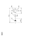
- FIG. 1 is a diagram showing an embodiment of a battery system.
- FIG. 2 is a block diagram illustrating a configuration for calculating an allowable current value.
- FIG. 3 is a diagram illustrating an example of a battery equivalent circuit model.
- FIG. 1 is a diagram showing an embodiment of a battery system 100, and shows an example of a battery system used in a battery power supply apparatus. Since the output voltage of the battery system 100 is a DC voltage that varies depending on the remaining capacity of the battery, the output current, and the like, it may not be suitable for supplying power directly to the load 111. Therefore, in the example shown in FIG. 1, the output voltage of the battery system 100 is converted into a three-phase alternating current by the inverter 110 and supplied to the load 111.
- the inverter 110 is controlled by a host controller 112 that controls the entire power converter.
- the same configuration is used when a DC voltage, other multiphase AC, or single phase AC is supplied to the load.
- the load 111 outputs electric power
- the electric power output from the load 111 can be stored in the battery module 105 by using the inverter 110 as a bidirectional inverter. Further, by connecting a charging system to the battery system 100 in parallel with the inverter 110, the battery module 105 can be charged as necessary.
- the battery system 100 includes a battery charge rate (SOC) and a deterioration rate (SOH) useful for controlling the inverter 110 and the load 111, a maximum charge / discharge current (allowable current value) that can be passed to the battery, battery temperature, and battery abnormality.
- SOC battery charge rate
- SOH deterioration rate
- Information related to the battery state such as the presence or absence of is transmitted to the host controller 112.
- the host controller 112 performs energy management, abnormality detection, and the like based on such information.
- the host controller 112 determines that the battery system 100 should be disconnected from the inverter 110 or the load 111, the host controller 112 transmits a disconnection instruction to the battery system 100.
- the battery system 100 includes one or more battery modules 105 including a plurality of batteries, a battery controller 101 that monitors, estimates, and controls the state of the battery system 100, a relay 106 that intermittently outputs the battery system 100, and a battery.
- a current sensor 108 that measures the current flowing through the battery, a voltage sensor 102 that measures the battery voltage, a leakage sensor 103 that measures the insulation resistance between the battery system 100 and, for example, ground, and the output voltage of the battery system 100
- a circuit breaker 107 provided and a temperature sensor 161 for measuring the battery temperature are provided.
- the battery controller 101 includes a CPU 601 that performs various calculations and a storage unit 602 that stores battery parameters to be described later.
- a battery system 100 shown in FIG. 1 includes two battery modules 105 connected in series via a circuit breaker 107.
- the battery module 105 includes a plurality of unit batteries, and includes a circuit that measures the temperature inside the module and the voltage of each unit battery, and a circuit that performs charging and discharging for each unit battery as necessary. As a result, voltage monitoring and voltage adjustment can be performed on a unit cell basis, and temperature information necessary for estimating a battery state whose characteristics change according to temperature can be measured. Details will be described later.
- a current sensor 108 and a pair of relays 106 are connected in series to the battery modules 105 connected in series.
- the current sensor 108 measures a current value necessary for monitoring / estimating the state of the battery module 105.
- the output of the battery system 100 can be cut off or connected.
- a circuit breaker 107 for manually shutting off power input / output to the battery system 100 may be added. By forcibly shutting off using the circuit breaker 107, it is possible to prevent an electric shock accident or a short-circuit accident when assembling or disassembling the battery system 100 or when dealing with an accident of a device equipped with the battery system 100. .
- a relay 106, a circuit breaker 107, and a current sensor 108 may be provided in each row, or the relay 106, circuit breaker only at the output portion of the battery system 100. 107 and a current sensor 108 may be provided. Moreover, the relay 106, the circuit breaker 107, and the current sensor 108 may be provided in both of each column and the output unit of the battery system 100.
- the relay 106 may be configured by one relay, or may be configured by a set of a main relay, a precharge relay, and a resistor. In the latter configuration, a resistor is arranged in series with the precharge relay, and these are connected in parallel with the main relay.
- a precharge relay is connected. Since the current flowing through the precharge relay is limited by the resistance connected in series, the inrush current that can occur in the former configuration can be limited. Then, after the current flowing through the precharge relay becomes sufficiently small, the main relay is connected.
- the main relay connection timing may be based on the current flowing through the precharge relay, or may be based on the voltage applied to the resistor or the voltage across the terminals of the main relay. Alternatively, the time elapsed since the precharge relay was connected may be used as a reference.
- the voltage sensor 102 measures a voltage value necessary for monitoring / estimating the state of the battery module 105.
- the voltage sensor 102 is connected in parallel to one or a plurality of battery modules 105, or connected in parallel to each series of battery modules 105.
- a leakage sensor 103 is connected to the battery module 105 to detect a state where a leakage can occur before the leakage occurs, that is, a state where the insulation resistance is reduced, thereby preventing an accident from occurring.
- Measured values of the battery module 105, current sensor 108, voltage sensor 102, and leakage sensor 103 are transmitted to the battery controller 101.
- the battery controller 101 monitors and estimates the battery state and controls the battery system 100 based on the received measurement value.
- the control includes, for example, charge / discharge of each unit battery for equalizing the voltage of each unit battery, power control of each sensor, addressing of the sensor, control of the relay 106 connected to the battery controller 101, and the like. Point to.
- the CPU 601 performs calculations necessary for battery state monitoring, estimation, and control.
- the battery system 100 may include a system cooling fan, and the battery controller 101 may control the fan. As described above, the battery system 100 performs the cooling until the amount of communication with the host controller can be reduced.
- the voltage sensor 102 and the leakage sensor 103 are provided with a degree of freedom by being separate from the battery controller 101, but the battery controller 101 includes the voltage sensor 102 and the leakage sensor 103. It is also good.
- the number of harnesses can be reduced as compared with the case of preparing individual sensors, and the labor for sensor installation can be reduced.
- the scale (maximum output voltage, current, etc.) of the battery system 100 that can be handled by the battery controller 101 may be limited by incorporating the sensor, in such a case, separate parts may be used. desirable.
- FIG. 2 is a block diagram illustrating a configuration for calculating an allowable current value.
- the allowable current value calculation is performed by the CPU 601.
- the CPU 601 includes a battery equivalent circuit model 702, a first allowable current value calculation unit 704, a polarization prediction unit 705, a correction amount calculation unit 706, and a second allowable current value calculation unit 707 as functional configurations.
- the database 703 is a battery parameter stored in the storage unit 602.
- the battery equivalent circuit model 702 is an equivalent circuit model for expressing the internal state of the unit battery.
- the first allowable current value calculation unit 704 calculates a first allowable current value when there is no polarization in the battery.
- the polarization prediction unit 705 predicts the polarization of the battery after a certain time.
- the correction amount calculation unit 706 calculates the influence of polarization on the first allowable current value calculated by the first allowable current value calculation unit 704 as a correction value (allowable current value correction value).
- the second allowable current value calculation unit 707 corrects the allowable current value calculated by the first allowable current value calculation unit 704 with the allowable current value correction value calculated by the correction amount calculation unit 706, and then corrects it. Output as a value.
- the battery equivalent circuit model 702 is based on the current value measured by the current sensor 108, the battery temperature measured by the temperature sensor 161, and the closed circuit voltage of the battery measured by the voltage sensor 102 (hereinafter referred to as CCV). Then, the SOC, OCV, and polarization voltage of the unit battery are estimated and output. In addition, as CCV, each CCV will be used if the voltage value measured with the voltage sensor 102 is converted per unit battery, or if the CCV for each unit battery can be obtained. By using such a battery equivalent circuit model 702, it is possible to estimate the internal state of the unit battery that cannot be observed directly, and use the estimated value for other processing.
- FIG. 3 is a diagram illustrating an example of the battery equivalent circuit model 702.
- OCV is represented by a voltage source 751
- DC resistance is represented by a resistor 752
- polarization resistance is represented by a resistor 753
- polarization capacitance is represented by a capacitor 754. Since these values change due to deterioration of the battery, values according to the deterioration are used.
- the polarization is initialized to zero, and by continuing to give the current value measured by the current sensor 108 to the battery equivalent circuit model 702, the battery equivalent circuit model 702 The current battery state can be expressed. Thereby, the polarization voltage can be calculated.
- a correlation table between SOC and OCV is stored in advance, and the initial value of SOC is obtained from this correlation table and the OCV taken as the initial voltage.
- the SOC is estimated from the initial value of the SOC and the integrated current value.
- the operating OCV can be estimated from the estimated SOC and the correlation table.
- the number of polarization terms is one, but the use of a plurality of terms makes it possible to increase the calculation accuracy.
- the initial value of the charge accumulated in the capacitor 754 is set to zero. This is because before the system is started, there is generally a rest time sufficiently longer than the time constant of the battery, and the capacitor 754 is completely discharged.
- the initialization is performed at the timing when the relay 106 is opened, such as when the battery system 100 is activated or when an initialization command value is received from the host controller 112.
- the database 703 is necessary for calculating the allowable current value based on the SOC output from the battery equivalent circuit model 702, the temperature output from the temperature sensor 161, and the current output from the current sensor 108.
- a lower limit voltage and a first resistor and a first gain described later are output. Since the OCV, SOC, and polarization voltage output from the battery equivalent circuit model 702 are values according to the current battery state, the upper and lower limit voltages, the first resistance, and the first gain output from the database 703 are also set to the current battery state. The value is in accordance. By using these output values, it is possible to calculate an allowable current value in accordance with the battery state.
- the first allowable current value calculation unit 704 calculates a first allowable current value Imax1 based on the OCV output from the battery equivalent circuit model 702, the upper and lower limit voltages output from the database 703, and the first resistance.
- Expression (1) shows an example of an arithmetic expression for the allowable charging current Icmax1.
- Icmax1 (Vmax-OCV) / R1 (1)
- Vmax is the upper limit voltage and R1 is the first resistor.
- the first resistance R1 is a resistance value (internal resistance) of the battery that is expected after a constant current is passed from the initialized non-polarized state and the constant current is passed for a predetermined time.
- the value of the first resistor R1 is acquired in advance through experiments, simulations, etc., and the value is stored in the database 703.
- the value is smaller than the first resistance R1. That is, the allowable charging current Icmax1 calculated by the equation (1) is smaller than the allowable charging current according to the current battery state (the allowable charging current calculated by substituting the current internal resistance into the equation (1)). .
- the calculated allowable charging current reaches Icmax1 when a predetermined time has elapsed.
- the allowable discharge current Idmax1 is also calculated in the same manner as in the case of the allowable charge current Icmax1, and is calculated by the following equation (2).
- Vmin is the lower limit voltage.
- the internal resistance after elapse of a predetermined time is set to the same first resistance R1 as in the case of charging.
- the charge / discharge current is controlled by the allowable current value (allowable charge current value, allowable discharge current value) Imax1 calculated using the first resistor R1, and the maximum current is continuously used within this range.
- the CCV does not reach the upper and lower limit voltages until a predetermined time elapses.
- the first allowable current value Imax1 calculated by the first allowable current value calculation unit 704 is an allowable current value when it is assumed that the current battery state is non-polarized. Therefore, if the current time is the time when the time has elapsed from the initialization timing, an error occurs because the current battery state is not unpolarized. Therefore, a polarization predicting unit 705, a correction amount calculating unit 706, and a second allowable current value calculating unit 07 are provided so that an accurate allowable current value can be obtained even when the current battery state is not unpolarized. Corrective processing is performed.
- the first allowable current value calculation unit 704 described above calculates the first allowable current value Imax1 using the first resistance R1 when a constant current flows for a predetermined time.
- Rp is a polarization resistance
- I is a current
- Vp0 is a current polarization voltage
- Cp is a polarization capacity
- t is a predetermined time.
- Vpt IRp- (IRp-Vp0) exp (-t / RpCp) (3)
- the first gain Gt is a parameter representing the temporal change (attenuation) of the polarization voltage, and is a constant determined by the magnitude of the predetermined time t.
- Vpt IRp (1-Gt) + Vp0 ⁇ Gt (4)
- the third term Vp0 ⁇ Gt in the equation (5) is a voltage depending on the current polarization voltage Vp0 and is calculated by the polarization prediction unit 705.
- Gt is referred to as a first gain
- the polarization voltage Vp0 is calculated by the battery equivalent circuit model 702, and the first gain Gt is output from the database 703.
- the polarization predicting unit 705 determines the first polarization voltage (the polarization voltage after a predetermined time t) based on the current polarization voltage Vp0 output from the battery equivalent circuit model 702 and the first gain Gt output from the database 703.
- Vp0 ⁇ Gt is calculated.
- the correction amount calculation unit 706 calculates the influence of polarization on the first allowable current value Imax1 calculated by the first allowable current value calculation unit 704 as the allowable current value correction value ⁇ I.
- the corrected allowable current value is referred to as a second allowable current value Imax2.
- the second allowable current value calculation unit 707 subtracts the allowable current value correction value ⁇ I calculated by the correction amount calculation unit 706 from the first allowable current value Imax1 calculated by the first allowable current value calculation unit 704 to obtain an equation ( The second allowable current value Imax2 represented by 6) is output.
- the first allowable current value calculated on the assumption that the current polarization is an unpolarized state is corrected with the allowable current value correction value ⁇ I calculated based on the current polarization voltage Vp0.
- the current during charging / discharging is controlled using the corrected second allowable current value Imax2. Since the second allowable current value Imax2 is calculated according to the polarization state of the battery, the largest current (that is, the allowable current value) at which the CCV does not reach the upper / lower limit voltage even if the current is allowed to flow for a predetermined time is calculated more accurately. Can do.
- charging and discharging are performed at intervals of about several seconds to 10 seconds.
- the current of a current value that can be output by the battery for example, 200 A
- the internal resistance when flowing to a certain extent is used. Therefore, a smaller allowable charging current is calculated as compared to the allowable charging current based on the battery state at the time of calculation. That is, the charging current is limited more than necessary.
- the allowable current value that can be passed at “this moment” is calculated.
- the allowable current value that can be allowed to flow “at this moment” as in the past is calculated. Therefore, when the control is performed based on the allowable current value, there is a possibility that the current cannot be continuously supplied at a constant current within the allowable current value range until “a predetermined time from now”.
- the predetermined time in the present embodiment is set according to the usage environment of the battery system 100. For example, when used in a hybrid vehicle, it is set to a time for which charging and discharging expected in a general vehicle use situation are continued.
- the value of the constant current is also set in consideration of the current value required according to general vehicle usage conditions. Set values for a predetermined time and a constant current are input from the host controller 112 in FIG.
- the correction amount calculation unit 706 calculates the influence of the polarization voltage on the allowable current value.
- the correction amount calculation unit 706 calculates the allowable current value correction value ⁇ I using the first polarization voltage Vp0 ⁇ Gt when the predetermined time t has passed as the polarization information. It is possible to calculate an allowable current value (second allowable current value Imax2) that can continue to flow for a certain period of time.
- the polarization voltage Vp0 output from the battery equivalent circuit model 702 is input to the correction amount calculation unit 706 as polarization information instead of the first polarization voltage Vp0 ⁇ Gt to correct the allowable current value.
- the value of the first resistance R1 corresponding to the internal resistance of the battery is stored in the database 703.
- the OCV change rate Gsoc per unit current (hereinafter referred to as the second gain), the polarization resistance Rp, and the first gain Gt)
- the first resistance R1 is expressed by the following equation (7). It may be obtained by calculation.
- the second gain Gsoc which is the OCV change rate per unit current, is omitted.
- equation (7) It is better to consider the second gain Gsoc as described above.
- R1 Rdc + Gsoc + Rp (1-Gt) (7)
- the battery controller 101 which is a battery control device, determines the battery current when an unpolarized state is assumed based on the open circuit voltage (OCV) of the battery and the upper and lower limit voltages (Vmax, Vmin) set for the battery.
- a first allowable current value calculation unit 704 that calculates a first allowable current value that is a limit value, a battery equivalent circuit model 702 that estimates the polarization state of the battery when the current limit value is calculated, and an estimated polarization state
- a polarization prediction unit 705, a correction amount calculation unit 706, and a second allowable current value calculation unit 707 as a correction unit that corrects the first allowable current value based on the first allowable current value are provided. Then, the corrected first allowable current value, that is, the second allowable current value Imax2 is output as the allowable charging / discharging current value of the battery.
- the first allowable current value calculated on the assumption that the current polarization is in an unpolarized state is corrected with the allowable current value correction value ⁇ I calculated based on the current polarization voltage Vp0. It is possible to calculate an accurate allowable current value.
- the first allowable current value calculation unit 704 determines the open circuit voltage (OCV) of the battery, the upper and lower limit voltages (Vmax, Vmin) set for the battery, and a predetermined current from the non-polarized state to the battery.
- the first allowable current value of the battery is calculated based on the first resistance R1 that is the battery internal resistance when the current flows for a time, and the polarization predicting unit 705 supplies the current in the polarization state estimated by the battery equivalent circuit model 702 to the current.
- the first polarization voltage Vp0 ⁇ Gt when maintaining the zero time for the predetermined time is calculated, and the first allowable current value is calculated using the allowable current value correction value ⁇ I corresponding to the calculated first polarization voltage Vp0 ⁇ Gt. You may make it correct
- an allowable current value (allowable charge / discharge current value) that allows a constant current to continue to flow for a predetermined time from the present time, and reliably control the current up to a predetermined time with a current within the allowable current value range.
- the first resistance R1 that is the battery internal resistance is determined based on the DC resistance Rdc of the battery, the second gain Gsoc that is the open circuit voltage change amount of the battery per unit current, and the polarization resistance Rp of the battery. You may make it calculate by Formula (7) mentioned above. By calculating the first resistance R1 in this way, it is possible to cope with parameter changes due to battery deterioration or the like.
- At least one of the first resistance R1, which is the battery internal resistance, the first gain Gt, which is a coefficient indicating the time change of the polarization voltage when the battery current is zero, and the upper / lower limit voltage It is good also as a value according to at least 1 of the temperature of this, a battery charge rate (SOC), and the electric current which flows through a battery.
- SOC battery charge rate
Landscapes
- Engineering & Computer Science (AREA)
- Power Engineering (AREA)
- Mechanical Engineering (AREA)
- Transportation (AREA)
- Sustainable Energy (AREA)
- Sustainable Development (AREA)
- Life Sciences & Earth Sciences (AREA)
- General Physics & Mathematics (AREA)
- Physics & Mathematics (AREA)
- General Chemical & Material Sciences (AREA)
- Electrochemistry (AREA)
- Chemical Kinetics & Catalysis (AREA)
- Chemical & Material Sciences (AREA)
- Manufacturing & Machinery (AREA)
- Automation & Control Theory (AREA)
- Secondary Cells (AREA)
- Charge And Discharge Circuits For Batteries Or The Like (AREA)
- Tests Of Electric Status Of Batteries (AREA)
- Electric Propulsion And Braking For Vehicles (AREA)
Abstract
電池の分極状態をより正確に反映した許容充放電電流値を得ることができる電池制御装置の提供。バッテリコントローラ101は、電池の開回路電圧OCVおよび電池に設定された上下限電圧Vmax,Vminに基づいて、無分極状態を仮定した場合の電池の電流制限値である第1許容電流値Imax1を算出する第1許容電流値演算部704と、前記電流制限値の算出時における電池の分極状態を推定する電池等価回路モデル702と、推定された分極状態に基づいて第1許容電流値Imax1を補正する許容電流値補正値ΔIを算出する補正量演算部706t、を備え、補正された第1許容電流値である第2許容電流値Imax2を、電池の許容充放電電流値として出力する。
Description
本発明は、電池システムの電池制御装置に関する。
近年、移動体向け蓄電装置や系統連系安定化用蓄電装置、非常用蓄電装置といった多数の電池を内蔵する電池システムが注目を浴びている。これらシステムの性能を引き出すには、電池の充電率(以下ではSOCと記載する)や劣化率(SOH)、充放電可能な最大電流(許容電流値)といったパラメータを算出して電池制御に利用したり、各電池の充電率を適切に揃えたりする必要がある。
これらを実現するため各電池には電池電圧計測用の回路(セルコントローラ)が取り付けられ、これらセルコントローラから送られてくる情報に基づき中央演算処理装置(CPU)を搭載したバッテリコントローラが前記演算や動作を実行するようにしている。許容電流値の演算は電池の過電圧を防ぐ安全機能の一部であり、許容電流値を超えないように電流を制限することで、電池システムの安全を維持している。
電池が過電圧とならない最大電流を演算するためには、電池の開放電圧(以下では、OCVと記載する)や内部抵抗情報等の電池の内部状態やパラメータを使う必要がある。特に、常時不規則な電流が流れている移動体向け蓄電装置では電池に生じる分極電圧の影響をする必要がある。前述したCPUの演算性能を考慮すると、特に移動体向けの許容電流値演算にはOCVや内部抵抗、分極電圧の影響を考慮した安全な電流を少ない計算量で算出することが要求される。しかし、分極電圧の演算には指数関数等の計算量が大きい関数を用いる必要がありCPUで演算することは困難であった。
そこで、電池に電流が連続して流れた時間を計測し、これを用いて分極電圧の影響を反映済みの抵抗値テーブルから許容電流値演算に用いる抵抗値を参照する手法が提案されている(例えば、特許文献1参照)。これによれば、指数関数等を用いること無く少ない計算量で許容電流値が算出可能となる。また、同じく特許文献1にあるように、ハイブリッド自動車のように電流が連続して流れる時間が短いアプリケーション向けでは充分大きな分極電圧に対応した固定の抵抗値を用いる手法が用いられている。これらの手法により、分極電圧が存在しても電池が過電圧とならない電流が、少ない計算量で算出可能となっている。
ところで、特許文献1に記載の発明では、分極電圧の影響を許容電流値演算に反映させるために、一定時間電流を流し続けた場合の抵抗値を用いている。しかし、実際には、想定した一定時間よりも短い時間で充電期間、放電期間、休止期間が切り替わる場合があり、実際の抵抗値は想定したものよりも小さくなる傾向にあった。そのため、許容電流値の値が制限過剰となることがあった。
本発明による電池制御装置は、電池の開回路電圧および電池に設定された上下限電圧に基づいて、無分極状態を仮定した場合の電池の電流制限値を算出する電流制限値算出部と、前記電流制限値の算出時における電池の分極状態を推定する推定部と、前記推定された分極状態に基づいて前記電流制限値を補正する補正部と、を備え、前記補正部により補正された電流制限値を、電池の許容充放電電流値として出力する。
本発明によれば、電池の分極状態をより正確に反映した許容充放電電流値を得ることができる。
以下、図を参照して本発明を実施するための形態について説明する。図1は、電池システム100の一実施の形態を示す図であり、電池電力供給装置に用いられる電池システムの一例を示す。電池システム100の出力電圧は、電池の残容量や出力電流等により変動する直流電圧のため、負荷111に直接電力を供給するには適さない場合がある。そこで、図1に示す例では、インバータ110により電池システム100の出力電圧を三相交流に変換し、負荷111に供給している。インバータ110、電力変換装置全体を制御する上位コントローラ112により制御される。
なお、負荷に直流電圧や他の多相交流、単相交流を供給する場合も同様の構成となる。また、負荷111が電力を出力する場合には、インバータ110を双方向インバータとすることにより、負荷111が出力した電力を電池モジュール105に蓄えることができる。また、インバータ110と並列に充電システムを電池システム100に接続することで、必要に応じ電池モジュール105を充電することも可能である。
電池システム100は、インバータ110や負荷111の制御に有用な電池の充電率(SOC)や劣化率(SOH)、電池に流すことができる最大充放電電流(許容電流値)、電池温度、電池異常の有無等の電池状態に関する情報を、上位コントローラ112に送信する。上位コントローラ112は、これらの情報に基づき、エネルギーマネージメントや異常検知等を行う。また、上位コントローラ112は、電池システム100をインバータ110または負荷111から切り離すべきと判断した場合は、切断指示を電池システム100に対し送信する。
電池システム100は、複数個の電池からなる1台以上の電池モジュール105と、電池システム100の状態を監視・推定・制御するバッテリコントローラ101と、電池システム100の出力を断続するリレー106と、電池に流れた電流を計測する電流センサ108と、電池電圧を計測する電圧センサ102と、電池システム100と例えばアースとの間の絶縁抵抗を計測する漏電センサ103と、電池システム100の出力電圧に応じ設けられる遮断器107と、電池温度を計測する温度センサ161を備えている。バッテリコントローラ101は、各種演算を行うCPU601、後述する電池パラメータが記憶される記憶部602を備えている。図1に示す電池システム100は、遮断器107を介して直列接続された2台の電池モジュール105を備えている。
電池モジュール105は複数個の単位電池を有し、モジュール内部の温度や各単位電池の電圧を計測する回路、および、必要に応じ単位電池単位での充放電を行う回路を備えている。これにより単位電池単位での電圧監視や電圧調整が可能となり、また温度に応じて特性が変化する電池状態の推定に必要な温度情報を計測可能となる。詳細は後述する。
直列接続された電池モジュール105には、電流センサ108と一対のリレー106とが直列に接続される。電流センサ108は、電池モジュール105の状態を監視・推定するために必要な電流値が計測する。一対のリレー106の開閉を上位コントローラの指令に基づき制御することで、電池システム100の出力を遮断または接続することができる。電池モジュール105の電圧が例えば100V以上の高電圧となる場合には、電池システム100への電力入出力を人力で遮断するための遮断器107を追加することがある。遮断器107を用いて強制的に遮断を行うことで、電池システム100の組み立て時や解体時、電池システム100を搭載した装置の事故対応時に感電事故や短絡事故の発生を防ぐことが可能となる。
なお、電池モジュール105が複数台並列に接続されている場合は、各列にリレー106、遮断器107、電流センサ108を設けてもよいし、電池システム100の出力部分にのみリレー106、遮断器107、電流センサ108を設けてもよい。また、各列および電池システム100の出力部の両方にリレー106、遮断器107、電流センサ108を設けてもよい。
リレー106は1台のリレーで構成してもよいし、メインリレーとプリチャージリレー、抵抗の組で構成してもよい。後者の構成ではプリチャージリレーと直列に抵抗を配置し、これらをメインリレーと並列接続する。そしてリレー106を接続する場合、まずプリチャージリレーを接続する。プリチャージリレーを流れる電流は直列接続した抵抗により制限されるため、前者の構成で生じうる突入電流を制限することができる。そしてプリチャージリレーを流れる電流が十分小さくなったのちにメインリレーを接続する。メインリレー接続のタイミングはプリチャージリレーを流れる電流を基準にしてもよいし、抵抗にかかる電圧やメインリレーの端子間電圧を基準にしてもよい。また、プリチャージリレーを接続してから経過した時間を基準にしてもよい。
電圧センサ102は、電池モジュール105の状態監視・推定に必要な電圧値を計測する。電圧センサ102は、1台または複数台の電池モジュール105に対して並列接続されたり、または、電池モジュール105の各1直列に対し並列に接続されたりする。また、電池モジュール105には漏電センサ103が接続され、漏電が生じる前に漏電が生じうる状態、すなわち絶縁抵抗が低下した状態を検知し事故の発生を予防可能とする。
電池モジュール105、電流センサ108、電圧センサ102、漏電センサ103の計測値はバッテリコントローラ101に送信される。バッテリコントローラ101は、受信した計測値に基づいて、電池状態の監視や推定、および電池システム100の制御を行う。ここで制御とは、例えば、各単位電池の電圧を均等化するための単位電池毎の充放電や、各センサの電源制御、センサのアドレッシング、バッテリコントローラ101に接続されたリレー106の制御等を指す。電池状態の監視や推定、制御に必要な演算はCPU601が行う。
なお、電池システム100にはシステム冷却用のファンが含まれてもよく、その制御をバッテリコントローラ101が行うこともある。このように冷却まで電池システム100が行うことで、上位コントローラとの通信量を削減することが可能となる。
図1に示す例では、電圧センサ102や漏電センサ103をバッテリコントローラ101とは別部品とすることで自由度を持たせているが、バッテリコントローラ101に電圧センサ102や漏電センサ103を内蔵する構成としても良い。内蔵構成とすることで、個別のセンサを用意する場合にくらべハーネス本数が減り、センサ取り付けの手間も削減できる。ただし、センサを内蔵することでバッテリコントローラ101が対応可能な電池システム100の規模(最大出力電圧、電流等)が限定されてしまう場合もあるので、そのような場合には別部品とするのが望ましい。
図2は、許容電流値を演算するための構成を説明するブロック図である。許容電流値演算は、CPU601において行われる。CPU601は、機能構成として、電池等価回路モデル702、第1許容電流値演算部704、分極予測部705、補正量演算部706、および第2許容電流値演算部707を備えている。なお、データベース703は、記憶部602に記憶されている電池パラメータである。
電池等価回路モデル702は、単位電池の内部状態を表現するための等価回路モデルである。第1許容電流値演算部704は、電池に分極が無かった場合の第1許容電流値を演算する。分極予測部705は、一定時間後の電池の分極を予測する。補正量演算部706は、第1許容電流値演算部704が算出した第1許容電流値に対する分極による影響を、補正値(許容電流値補正値)として算出する。第2許容電流値演算部707は、第1許容電流値演算部704が算出した許容電流値を補正量演算部706で算出された許容電流値補正値で補正して、それを第2許容電流値として出力する。
電池等価回路モデル702は、電流センサ108で計測された電流値、温度センサ161で計測された電池温度、電圧センサ102で計測された電池の閉回路電圧(以下では、CCVと記載する)に基づいて、単位電池のSOCやOCV、分極電圧を推定し出力する。なお、CCVとしては、電圧センサ102で計測された電圧値を単位電池当たりに換算したものや、単位電池毎のCCVが取得できる構成であれば各々のCCVが使用される。このような電池等価回路モデル702を用いることで、直接は観測することができない単位電池の内部状態を推定することができ、その推定値を他の処理に使用することが可能となる。
図3は、電池等価回路モデル702の一例を示す図である。図3に示す例では、OCVを電圧源751で表現し、直流抵抗を抵抗752で表現し、分極抵抗を抵抗753で表現し、分極容量をキャパシタ754で表現している。これらの値は電池の劣化により変化するので、劣化に応じた値が用いられる。初期電圧をOCVとして電池等価回路モデル702に与えることで分極がゼロの状態に初期化し、電池等価回路モデル702に電流センサ108で計測された電流値を与え続けることで、電池等価回路モデル702により現在の電池状態を表現することができる。それにより、分極電圧を算出可能としている。
例えば、予めSOCとOCVとの相関テーブルを記憶しておき、この相関テーブルと、初期電圧として取り込んだOCVとから、SOCの初期値を求める。動作中は、例えば、SOCの初期値と電流積算値とからSOCを推定する。推定したSOCと相関テーブルとから、動作中のOCVを推定することができる。
なお、図3に示す例では分極の項を1個としているが、複数個用いることで演算をより高精度化することが可能である。初期化において、キャパシタ754に溜まっている電荷の初期値は0とする。これは、システム起動前には一般的に電池の時定数より充分長い休止時間が存在し、キャパシタ754が完全放電しているためである。初期化は、電池システム100の起動時や、上位コントローラ112からの初期化指令値受信時等の、リレー106が開いているタイミングにおいて行われる。
図2に戻って、データベース703は、電池等価回路モデル702から出力されたSOC、温度センサ161から出力された温度、および電流センサ108から出力された電流に基づき、許容電流値演算に必要な上下限電圧と、後述する第1抵抗および第1ゲインとを出力する。電池等価回路モデル702から出力されるOCV,SOCおよび分極電圧は現在の電池状態に応じた値なので、データベース703から出力される上下限電圧、第1抵抗および第1ゲインも、現在の電池状態に応じた値となっている。これらの出力値を用いることにより、電池状態に則した許容電流値演算が可能となる。
このように、出力データの値をマップに基づいて求めることにより、計算量の削減や、理論式が不明な特性への対応が可能となる。また、近似式により出力してもよい。これにより、データ量の削減や出力値の精度向上が可能となる。
第1許容電流値演算部704は、電池等価回路モデル702が出力したOCV、データベース703が出力した上下限電圧および第1抵抗に基づき、第1許容電流値Imax1を演算する。式(1)は、許容充電電流Icmax1の演算式の一例を示したものである。
Icmax1=(Vmax-OCV)/R1 …(1)
Icmax1=(Vmax-OCV)/R1 …(1)
式(1)において、Vmaxは上限電圧、R1は第1抵抗である。ここで、第1抵抗R1は、初期化された無分極状態から一定電流を流した場合を仮定し、その一定電流を所定時間流した後に予想される電池の抵抗値(内部抵抗)である。本実施の形態では、第1抵抗R1の値を予め実験やシミュレーション等で取得し、その値がデータベース703に格納されている。
演算時点(現在)における電池の内部抵抗は分極ゼロの状態の内部抵抗なので、上記第1抵抗R1よりも値が小さい。すなわち、式(1)により算出される許容充電電流Icmax1は、現在の電池状態に応じた許容充電電流(式(1)に現在の内部抵抗を代入して算出される許容充電電流)よりも小さい。そして、無分極状態から一定電流を流し続けた場合、所定時間経過したとき、算出される許容充電電流はIcmax1に達する。
なお、許容放電電流Idmax1についても許容充電電流Icmax1の場合と同様に考え、次式(2)により算出する。Vminは下限電圧である。なお、式(2)では所定時間経過後の内部抵抗を充電の場合と同一の第1抵抗R1としたが、実際の電池では充電方向と放電方向とでは値が異なっており、ここでも電流方向に応じた値を用いるのが好ましい。
Idmax=(OCV-Vmin)/R1 …(2)
Idmax=(OCV-Vmin)/R1 …(2)
このように、第1抵抗R1を用いて算出された許容電流値(許容充電電流値、許容放電電流値)Imax1により充放電電流を制御することで、この範囲内で最大電流を使用し続けても所定時間経過するまではCCVが上下限電圧に達することがない。
なお、第1許容電流値演算部704で算出される第1許容電流値Imax1は、現時点での電池状態が無分極であると仮定した場合の許容電流値である。そのため、現時点が初期化タイミングから時間が経過した時点である場合、現時点の電池状態は無分極ではないので誤差が生じる。そこで、現時点の電池状態が無分極でない場合にも正確な許容電流値が得られるように、分極予測部705、補正量演算部706、および第2許容電流値演算部07を設けて以下のような補正処理を行う。
ところで、上述した第1許容電流値演算部704では一定電流が所定時間流れた場合の第1抵抗R1を用いて第1許容電流値Imax1を算出した。このように一定電流が流れている場合の所定時間後の分極電圧を予測するためには、一般に、指数関数を用いた次式(3)を用いる必要がある。ただし、Vptは所定時間後の分極電圧、Rpは分極抵抗、Iは電流、Vp0は現在の分極電圧、Cpは分極容量であり、tは所定時間である。
Vpt=IRp-(IRp-Vp0)exp(-t/RpCp) …(3)
Vpt=IRp-(IRp-Vp0)exp(-t/RpCp) …(3)
式(3)の右辺を、分極電圧Vp0を含まない項と、分極電圧Vp0を含む項とに分けて記載すると次式(4)になる。なお、Gt=exp(-t/RpCp)である。式(4)においてI=0とした場合、Vpt=Vp0・Gtとなる。電池に流れる電流をゼロとすると、時間の経過とともに分極電圧は減少する。そして、値Vp0の分極電圧は、時間の経過と共に減少し、所定時間tが経過したときにVpt=Vp0・Gtとなる。このように、第1ゲインGtは分極電圧の時間的な変化(減衰)を表すパラメータであり、所定時間tの大きさによって決まる定数である。
Vpt=IRp(1-Gt)+Vp0・Gt …(4)
Vpt=IRp(1-Gt)+Vp0・Gt …(4)
式(4)を用いて図3のOCV,CCV,Rdcの関係を表すと、次式(5)のようになる。なお、Iは電池を流れる電流である。
CCV=OCV+I・Rdc+Vpt
=OCV+I・Rdc+IRp(1-Gt)+Vp0・Gt
=OCV+I(Rdc+Rp(1-Gt))+Vp0・Gt …(5)
CCV=OCV+I・Rdc+Vpt
=OCV+I・Rdc+IRp(1-Gt)+Vp0・Gt
=OCV+I(Rdc+Rp(1-Gt))+Vp0・Gt …(5)
上述した第1許容電流値演算部704で算出される許容充電電流Icmax1は、式(5)においてVp0=0と考え、第2項の「Rdc+Rp(1-Gt)」の部分を第1抵抗R1とした場合に相当する。そして、式(5)の第3項=Vp0・Gtは、現時点における分極電圧Vp0に依存する電圧であり、分極予測部705において算出される。本実施形態では、Gtを第1ゲインと呼び、第3項=Vp0・Gtを第1分極電圧と呼ぶことにする。分極電圧Vp0は電池等価回路モデル702によって算出され、第1ゲインGtはデータベース703から出力される。
すなわち、分極予測部705は、電池等価回路モデル702が出力する現時点の分極電圧Vp0と、データベース703が出力する第1ゲインGtとに基づき、所定時間t後の分極電圧である第1分極電圧(Vp0・Gt)を算出する。分極電圧Vp0の電池を電流ゼロの状態で放置すると徐々に分極電圧が低下するが、所定時間tが経過したときの分極電圧が第1分極電圧(Vp0・Gt)である。
このように、指数関数で表される第1ゲインGtをデータベース703から出力する構成とすることで、計算量の多い指数関数を不要とすることができ、計算能力に制約のある組み込み向けCPUでも一定時間後の分極電圧が容易に演算可能となる。
補正量演算部706は、第1許容電流値演算部704が算出した第1許容電流値Imax1に対する分極による影響を、許容電流値補正値ΔIとして算出する。上述したように、第1許容電流値Imax1は、式(5)でVp0=0とした場合の電流値である。そのため、Vp0≠0の場合の許容電流値(すなわち補正後に得られる許容電流値)は、第1許容電流値Imax1よりも許容電流値補正値ΔIだけ小さくなる。ここでは、補正後の許容電流値を第2許容電流値Imax2と呼ぶことにする。
式(5)においてCCV=Vmax、I=Icmax2のように置き換えて式変形すると、次式(6)が得られる。すなわち、許容電流値補正値ΔIは、ΔI=Vp0・Gt/R1のように算出される。
Icmax2=(Vmax-OCV)/(Rdc+Rp(1-Gt))-Vp0・Gt/(Rdc+Rp(1-Gt))
=(Vmax-OCV)/R1-Vp0・Gt/R1 …(6)
Icmax2=(Vmax-OCV)/(Rdc+Rp(1-Gt))-Vp0・Gt/(Rdc+Rp(1-Gt))
=(Vmax-OCV)/R1-Vp0・Gt/R1 …(6)
第2許容電流値演算部707は、第1許容電流値演算部704が算出した第1許容電流値Imax1から補正量演算部706で算出された許容電流値補正値ΔIをマイナスして、式(6)で表される第2許容電流値Imax2を出力する。
このように、本実施の形態では、現時点の分極が無分極状態であると仮定して算出した第1許容電流値を、現時点の分極電圧Vp0に基づいて算出した許容電流値補正値ΔIで補正し、その補正された第2許容電流値Imax2を用いて充放電時の電流を制御するようにした。第2許容電流値Imax2は電池の分極状況に応じて算出されるので、所定時間流し続けてもCCVが上下限電圧に到達しない最も大きい電流(すなわち許容電流値)を、より正確に算出することができる。なお、上述した説明では所定時間tについてt≠0の場合を例に説明しているが、t=0の場合にも適用することができる。
従来、現時点の電池状態における許容充放電電流を算出する場合、現時点の内部抵抗を正確に知る必要がある。例えば、現時点の電池状態における許容充電電流を算出する場合には、式(1)において第1抵抗の代わりに現時点の内部抵抗を用いることで算出することができる。この内部抵抗は電池の分極状態に依存しているが、上述した特許文献1に記載の技術では、現時点の分極状態を推定する代わりに、一定の電流が一定時間流れた時の電池の内部抵抗を代用している。
例えば、ハイブリッド自動車に搭載される電池システムでは、数秒~10秒程度の間隔で充電、放電が行われるので、一例として、電池が出力可能な電流値(例えば、200A)の電流が3~5秒程度流れたときの内部抵抗が用いられる。そのため、算出時点の電池状態に基づく許容充電電流に比べて、より小さな許容充電電流が算出されることになる。
すなわち、必要以上に充電電流を制限してしまうことになる。
すなわち、必要以上に充電電流を制限してしまうことになる。
ところで、従来の技術では、「今この瞬間」に流すことが可能な許容電流値を演算している。しかし、エネルギー管理の観点等から「今から一定時間」流し続けることが可能な許容電流値を演算することが求められはじめている。従来のように「今この瞬間」に流すことが可能な許容電流値を演算している。そのため、その許容電流値に基づいて制御した場合に、「今から所定時間」まで許容電流値範囲内の一定電流で流し続けられないおそれがある。一方、本実施の形態では、一定の電流を現時点から所定時間流し続けることが可能な許容電流値を算出することができる。そのため、その許容電流値範囲内の電流で確実に所定時間まで制御することができる。
なお、本実施の形態における所定時間は、電池システム100の使用環境に応じて設定される。例えば、ハイブリッド自動車に用いられる場合には、一般的な車両使用状況において予想される充電、放電が継続される時間程度に設定される。一定電流の値についても、一般的な車両使用状況に応じて要求される電流値などを考慮して設定される。所定時間および一定電流に関する設定値は、図1の上位コントローラ112から入力される。
ところで、補正量演算部706は、分極電圧が許容電流値に与える影響を算出するものである。図2に示す例では、補正量演算部706は、分極情報として所定時間tが経過したときの第1分極電圧Vp0・Gtを用いて許容電流値補正値ΔIを算出しているので、確実に一定時間流し続けられる許容電流値(第2許容電流値Imax2)の演算が可能となる。
なお、図2示す処理とは異なるが、分極情報として、第1分極電圧Vp0・Gtに代えて電池等価回路モデル702の出力する分極電圧Vp0を補正量演算部706に入力し、許容電流値補正値ΔIを、ΔI=Vp0/R1のように算出しても良い。これは、Gt(0)=1、すなわちt=0のときの第1ゲインを用いることに相当する。第1ゲインGtはGt=exp(-t/RpCp)であるので、t=0のときが最も大きく、時間の経過と共に減少する。よって、分極情報として分極電圧Vp0を用いる場合、分極電圧を大きめに見積もることになる。そのため、許容電流値は小さくなるが、安全をより確実に担保することができる。
なお、分極電圧に固定値を掛けて利用することで分極電圧の影響を調整することができ、電池等価回路モデル702の分極電圧推定誤差による過電圧を防ぐことが可能となる。
上述した実施形態では、電池の内部抵抗に相当する第1抵抗R1の値を、データベース703に格納するという構成とした。しかし、電池の直流抵抗Rdc、単位電流あたりのOCV変化率Gsoc(以下では、第2ゲインと呼ぶ)、分極抵抗Rp、第1ゲインGtから、次式(7)のように第1抵抗R1を計算で求めても良い。このように第1抵抗R1を間接的に計算することで、電池の劣化等によるパラメータ変化に対応することが可能となる。なお、上述した式(5)においては、単位電流あたりのOCV変化率である第2ゲインGsocを省略して説明したが、第1抵抗R1をより正確に表現するためには、式(7)のように第2ゲインGsocも考慮した方が良い。
R1=Rdc+Gsoc+Rp(1-Gt) …(7)
R1=Rdc+Gsoc+Rp(1-Gt) …(7)
上述した実施の形態では、以下のような作用効果を奏することができる。
(a)電池制御装置であるバッテリコントローラ101は、電池の開回路電圧(OCV)および電池に設定された上下限電圧(Vmax,Vmin)に基づいて、無分極状態を仮定した場合の電池の電流制限値である第1許容電流値を算出する第1許容電流値演算部704と、前記電流制限値の算出時における電池の分極状態を推定する電池等価回路モデル702と、推定された分極状態に基づいて第1許容電流値を補正する補正部としての分極予測部705、補正量演算部706および第2許容電流値演算部707、を備える。そして、補正された第1許容電流値、すなわち第2許容電流値Imax2を、電池の許容充放電電流値として出力する。
(a)電池制御装置であるバッテリコントローラ101は、電池の開回路電圧(OCV)および電池に設定された上下限電圧(Vmax,Vmin)に基づいて、無分極状態を仮定した場合の電池の電流制限値である第1許容電流値を算出する第1許容電流値演算部704と、前記電流制限値の算出時における電池の分極状態を推定する電池等価回路モデル702と、推定された分極状態に基づいて第1許容電流値を補正する補正部としての分極予測部705、補正量演算部706および第2許容電流値演算部707、を備える。そして、補正された第1許容電流値、すなわち第2許容電流値Imax2を、電池の許容充放電電流値として出力する。
現時点の分極が無分極状態であると仮定して算出した第1許容電流値を、現時点の分極電圧Vp0に基づいて算出した許容電流値補正値ΔIで補正しているので、電池の状況に応じた正確な許容電流値を算出することができる。
(b)さらに、第1許容電流値演算部704は、電池の開回路電圧(OCV)、電池に設定された上下限電圧(Vmax,Vmin)、および、電池に一定電流を無分極状態から所定時間流した場合の電池内部抵抗である第1抵抗R1に基づいて、電池の第1許容電流値を算出し、分極予測部705は、電池等価回路モデル702で推定された分極状態の電池を電流ゼロの状態に前記所定時間維持したときの第1分極電圧Vp0・Gtを算出し、算出された第1分極電圧Vp0・Gtに対応する許容電流値補正値ΔIを用いて第1許容電流値を補正するようにしても良い。
その結果、一定の電流を現時点から所定時間流し続けることが可能な許容電流値(許容充放電電流値)を算出することができ、その許容電流値範囲内の電流で確実に所定時間まで制御することができる。なお、許容電流値補正値ΔIを、電池内部抵抗である第1抵抗R1と第1分極電圧Vp0・Gtとを用いて、ΔI=Vp0・Gt/R1のように算出するようにしても良い。
(c)また、電池内部抵抗である第1抵抗R1を、電池の直流抵抗Rdc、単位電流当たりの電池の開回路電圧変化量である第2ゲインGsoc、および電池の分極抵抗Rpに基づいて、上述した式(7)で算出するようにしても良い。このように第1抵抗R1を計算することで、電池の劣化等によるパラメータ変化に対応することが可能となる。
(d)また、電池内部抵抗である第1抵抗R1、電池の電流をゼロとした場合の分極電圧の時間変化を示す係数である第1ゲインGt、および上下限電圧の少なくとも一つを、電池の温度、電池の充電率(SOC)および電池を流れる電流の少なくとも一つに応じた値としても良い。
上記では、種々の実施の形態および変形例を説明したが、本発明はこれらの内容に限定されるものではない。本発明の技術的思想の範囲内で考えられるその他の態様も本発明の範囲内に含まれる。
100…電池システム、101…バッテリコントローラ、102…電圧センサ、105…電池モジュール、108…電流センサ、161…温度センサ、601…CPU、602…記憶部、702…電池等価回路モデル、703…データベース、704…第1許容電流値演算部、705…分極予測部、706…補正量演算部、707…第2許容電流値演算部、Imax1…第1許容電流値、Imax2…第2許容電流値、Gsoc…OCV変化率(第2ゲイン)、Gt…第1ゲイン、R1…第1抵抗、Vmax…上限電圧、Vmin…下限電圧、Vp0…分極電圧、Vp0・Gt…第1分極電圧、ΔI…許容電流値補正値
Claims (7)
- 電池の開回路電圧および電池に設定された上下限電圧に基づいて、無分極状態を仮定した場合の電池の電流制限値を算出する電流制限値算出部と、
前記電流制限値の算出時における電池の分極状態を推定する推定部と、
前記推定された分極状態に基づいて前記電流制限値を補正する補正部と、を備え、
前記補正部により補正された電流制限値を、電池の許容充放電電流値として出力する、電池制御装置。 - 請求項1に記載の電池制御装置において、
前記電流制限値算出部は、電池の開回路電圧、電池に設定された上下限電圧、および、電池に一定電流を無分極状態から所定時間流した場合の電池内部抵抗に基づいて、電池の電流制限値を算出し、
前記補正部は、前記推定部で推定された分極状態の電池を電流ゼロの状態に前記所定時間維持したときの分極電圧を算出し、算出された分極電圧に対応する補正電流値を用いて前記電流制限値を補正する、電池制御装置。 - 請求項2に記載の電池制御装置において、
前記電池内部抵抗は、電池の直流抵抗、単位電流当たりの電池の開回路電圧変化量および電池の分極抵抗に基づいて算出される、電池制御装置。 - 請求項2に記載の電池制御装置において、
前記補正部は、前記電池内部抵抗と前記分極電圧とに基づいて、前記補正電流値を算出する、電池制御装置。 - 請求項2に記載の電池制御装置において、
前記分極電圧は、電池の電流をゼロとした場合の分極電圧の時間変化を示す係数と、前記推定部で推定された分極状態における分極電圧との積で算出される、電池制御装置。 - 請求項2に記載の電池制御装置において、
前記推定部で推定される分極状態は、電池制御装置の起動時、または、電池に接続されている負荷の起動時に初期化される、電池制御装置。 - 請求項5に記載の電池制御装置において、
前記電池内部抵抗、電池の電流をゼロとした場合の分極電圧の時間変化を示す前記係数、および前記上下限電圧の少なくとも一つは、電池の温度、電池の充電率および電池を流れる電流の少なくとも一つに応じた値とされる、電池制御装置。
Priority Applications (6)
| Application Number | Priority Date | Filing Date | Title |
|---|---|---|---|
| CN202010810994.9A CN111987765B (zh) | 2015-07-02 | 2016-04-27 | 电池控制装置和电池组 |
| EP16817550.3A EP3319197B1 (en) | 2015-07-02 | 2016-04-27 | Battery control device |
| US15/738,994 US10680453B2 (en) | 2015-07-02 | 2016-04-27 | Battery control device |
| EP21155106.4A EP3849044B1 (en) | 2015-07-02 | 2016-04-27 | Battery control device |
| CN201680025915.5A CN107534309B (zh) | 2015-07-02 | 2016-04-27 | 电池控制装置 |
| US16/876,802 US11247581B2 (en) | 2015-07-02 | 2020-05-18 | Battery control device |
Applications Claiming Priority (2)
| Application Number | Priority Date | Filing Date | Title |
|---|---|---|---|
| JP2015-133913 | 2015-07-02 | ||
| JP2015133913A JP6383704B2 (ja) | 2015-07-02 | 2015-07-02 | 電池制御装置 |
Related Child Applications (2)
| Application Number | Title | Priority Date | Filing Date |
|---|---|---|---|
| US15/738,994 A-371-Of-International US10680453B2 (en) | 2015-07-02 | 2016-04-27 | Battery control device |
| US16/876,802 Continuation US11247581B2 (en) | 2015-07-02 | 2020-05-18 | Battery control device |
Publications (1)
| Publication Number | Publication Date |
|---|---|
| WO2017002440A1 true WO2017002440A1 (ja) | 2017-01-05 |
Family
ID=57608462
Family Applications (1)
| Application Number | Title | Priority Date | Filing Date |
|---|---|---|---|
| PCT/JP2016/063128 Ceased WO2017002440A1 (ja) | 2015-07-02 | 2016-04-27 | 電池制御装置 |
Country Status (5)
| Country | Link |
|---|---|
| US (2) | US10680453B2 (ja) |
| EP (2) | EP3319197B1 (ja) |
| JP (2) | JP6383704B2 (ja) |
| CN (2) | CN111987765B (ja) |
| WO (1) | WO2017002440A1 (ja) |
Cited By (3)
| Publication number | Priority date | Publication date | Assignee | Title |
|---|---|---|---|---|
| CN110297185A (zh) * | 2019-08-14 | 2019-10-01 | 莆田市烛火信息技术有限公司 | 一种新能源汽车电池参数动态监测系统 |
| CN110525269A (zh) * | 2019-04-25 | 2019-12-03 | 吉林大学 | Soc的电池组均衡控制方法 |
| WO2026062946A1 (ja) * | 2024-09-20 | 2026-03-26 | ビークルエナジージャパン株式会社 | 電池制御装置及び電池制御方法 |
Families Citing this family (28)
| Publication number | Priority date | Publication date | Assignee | Title |
|---|---|---|---|---|
| CN107884723B (zh) * | 2017-12-28 | 2019-04-30 | 爱驰汽车(上海)有限公司 | 动力电池荷电状态初值获取方法、系统、设备及存储介质 |
| JP7024448B2 (ja) * | 2018-01-29 | 2022-02-24 | トヨタ自動車株式会社 | 電動車両 |
| KR102373449B1 (ko) * | 2018-02-01 | 2022-03-10 | 주식회사 엘지에너지솔루션 | 배터리의 전력 한계 결정 방법 및 배터리 관리 시스템 |
| US11404899B2 (en) * | 2018-06-27 | 2022-08-02 | Panasonic Intellectual Property Management Co., Ltd. | Battery system and battery management device for cancelling polarization voltage by applying a reverse current |
| CN110758127B (zh) * | 2018-07-26 | 2022-03-15 | 比亚迪股份有限公司 | 电池充电的方法、装置、存储介质及电子设备 |
| CN112912747B (zh) * | 2018-07-30 | 2023-07-11 | 日本汽车能源株式会社 | 电池状态推算装置和电池控制装置 |
| JP7091999B2 (ja) * | 2018-11-09 | 2022-06-28 | トヨタ自動車株式会社 | 電池制御装置 |
| JP7240893B2 (ja) * | 2019-02-18 | 2023-03-16 | ビークルエナジージャパン株式会社 | 電池制御装置 |
| KR102645052B1 (ko) * | 2019-03-05 | 2024-03-08 | 현대자동차주식회사 | 하이브리드 차량의 주행모드 제어 장치 및 그 방법 |
| CN110077282B (zh) * | 2019-05-16 | 2021-02-26 | 上海楞次新能源汽车科技有限公司 | 新能源汽车的燃料电池在线寿命检测方法、系统和装置 |
| CN113994222B (zh) * | 2019-06-07 | 2025-06-03 | 日本汽车能源株式会社 | 电池控制装置 |
| JP7236787B2 (ja) * | 2019-07-03 | 2023-03-10 | ビークルエナジージャパン株式会社 | 電池制御装置 |
| US11360535B2 (en) * | 2019-09-27 | 2022-06-14 | Saft America, Inc. | Management of a pre-charge circuit of a battery management system |
| KR102874965B1 (ko) * | 2019-12-19 | 2025-10-22 | 주식회사 엘지에너지솔루션 | 급속 충전용 전류 패턴 업데이트 장치, 방법 및 이를 수행하는 저장매체에 저장된 컴퓨터 프로그램 |
| JP7226296B2 (ja) * | 2019-12-19 | 2023-02-21 | トヨタ自動車株式会社 | 車両、車両制御システム |
| JP7279631B2 (ja) * | 2019-12-26 | 2023-05-23 | トヨタ自動車株式会社 | 車両の走行制御システム、車両および車両の制御方法 |
| US11454673B2 (en) * | 2020-02-12 | 2022-09-27 | Karma Automotive Llc | Battery current limits estimation based on RC model |
| DE102020215297A1 (de) * | 2020-12-03 | 2022-06-09 | Robert Bosch Gesellschaft mit beschränkter Haftung | Verfahren und Vorrichtung zum Betreiben eines Systems zum Bereitstellen von prädizierten Alterungszuständen von elektrischen Energiespeichern für ein Gerät mithilfe von maschinellen Lernverfahren |
| CN112937302A (zh) * | 2021-01-25 | 2021-06-11 | 中国第一汽车股份有限公司 | 一种高压监控方法、装置、存储介质及系统 |
| JP7487694B2 (ja) * | 2021-03-23 | 2024-05-21 | 株式会社デンソー | 電池装置 |
| JP7537334B2 (ja) * | 2021-03-26 | 2024-08-21 | トヨタ自動車株式会社 | 電池システムおよび二次電池の分極電圧の推定方法 |
| CN115133592A (zh) * | 2021-03-26 | 2022-09-30 | 华为数字能源技术有限公司 | 一种电池管理系统 |
| FR3122536B1 (fr) * | 2021-04-29 | 2023-06-30 | Psa Automobiles Sa | Contrôle d'un ensemble électrique pour une batterie électrique d'un véhicule automobile |
| CN113300016B (zh) * | 2021-05-21 | 2022-12-13 | 广州小鹏汽车科技有限公司 | 一种电池充放电控制方法和装置 |
| FR3133158B1 (fr) * | 2022-03-04 | 2026-02-20 | Psa Automobiles Sa | Procédé de gestion énergetique d’une prise d’alimentation d’accessoire dans un véhicule automobile à l’arrêt |
| WO2023190988A1 (ja) * | 2022-03-30 | 2023-10-05 | ビークルエナジージャパン株式会社 | 電池制御装置及び電池制御方法 |
| CN115079014A (zh) * | 2022-08-02 | 2022-09-20 | 广汽埃安新能源汽车有限公司 | 一种磷酸铁锂电池荷电状态的估算方法、装置及设备 |
| FR3161036A1 (fr) * | 2024-04-04 | 2025-10-10 | Electricite De France | Procédé et système de surveillance d’une batterie par suivide sa tension et de son courant |
Citations (2)
| Publication number | Priority date | Publication date | Assignee | Title |
|---|---|---|---|---|
| WO2011045853A1 (ja) * | 2009-10-14 | 2011-04-21 | 株式会社 日立製作所 | 電池制御装置およびモーター駆動システム |
| JP2011103748A (ja) * | 2009-11-11 | 2011-05-26 | Sanyo Electric Co Ltd | 電池の充放電可能電流演算方法及び電源装置並びにこれを備える車両 |
Family Cites Families (45)
| Publication number | Priority date | Publication date | Assignee | Title |
|---|---|---|---|---|
| JPH117984A (ja) * | 1997-06-13 | 1999-01-12 | Sony Corp | 2次電池の容量検出方法 |
| JPH1138107A (ja) | 1997-07-19 | 1999-02-12 | Toyota Central Res & Dev Lab Inc | 二次電池の残存容量推定方法 |
| TW201006846A (en) * | 2000-03-07 | 2010-02-16 | Senomyx Inc | T1R taste receptor and genes encidung same |
| US20020120906A1 (en) * | 2000-07-17 | 2002-08-29 | Lei Xia | Behavioral modeling and analysis of galvanic devices |
| TW201022287A (en) * | 2001-01-03 | 2010-06-16 | Senomyx Inc | T1R taste receptors and genes encoding same |
| JP4157317B2 (ja) * | 2002-04-10 | 2008-10-01 | 株式会社日立製作所 | 状態検知装置及びこれを用いた各種装置 |
| CN1879251B (zh) * | 2003-07-02 | 2011-10-12 | 伊顿动力品质有限公司 | 电池浮充管理 |
| CN100520431C (zh) * | 2003-07-29 | 2009-07-29 | 松下电动车辆能源股份有限公司 | 二次电池的充放电电量推定方法及装置 |
| US7570024B2 (en) * | 2004-04-06 | 2009-08-04 | Cobasys, Llc | Battery state of charge voltage hysteresis estimator |
| US7209841B2 (en) * | 2004-11-15 | 2007-04-24 | Cobasys, Llc | Maximum and minimum power limit calculator for batteries and battery subpacks |
| US20060103348A1 (en) * | 2004-11-15 | 2006-05-18 | Melichar Robert J | Maximum and minimum power limit calculator for parallel battery subpacks |
| US7315789B2 (en) * | 2004-11-23 | 2008-01-01 | Lg Chem, Ltd. | Method and system for battery parameter estimation |
| EP1843164A4 (en) * | 2005-01-27 | 2009-06-03 | Panasonic Ev Energy Co Ltd | METHOD AND DEVICE FOR ESTIMATING THE LOADING DISCHARGE ELECTRICITY AMOUNT OF A SECONDARY CELL, METHOD AND DEVICE FOR ESTIMATING THE POLARIZATION VOLTAGE OF A SECONDARY CELL AND METHOD AND DEVICE FOR ESTIMATING THE REMAINING CAPACITY OF A SECONDARY CELL |
| JP4767558B2 (ja) * | 2005-03-07 | 2011-09-07 | 日立ビークルエナジー株式会社 | 電源装置用状態検知装置,電源装置及び電源装置に用いられる初期特性抽出装置 |
| JP5089883B2 (ja) * | 2005-12-16 | 2012-12-05 | 日立ビークルエナジー株式会社 | 蓄電池管理装置 |
| US8466684B2 (en) * | 2006-06-16 | 2013-06-18 | Chevron Technology Ventures Llc | Determination of battery predictive power limits |
| KR100804698B1 (ko) * | 2006-06-26 | 2008-02-18 | 삼성에스디아이 주식회사 | 배터리 soc 추정 방법 및 이를 이용하는 배터리 관리시스템 및 구동 방법 |
| JP4866187B2 (ja) * | 2006-09-05 | 2012-02-01 | プライムアースEvエナジー株式会社 | 電池制御装置、電動車両、及び二次電池の充電状態を推定するための処理をコンピュータに実行させるためのプログラム |
| JP4872743B2 (ja) * | 2007-03-23 | 2012-02-08 | トヨタ自動車株式会社 | 二次電池の状態推定装置 |
| JP5009223B2 (ja) * | 2008-04-25 | 2012-08-22 | プライムアースEvエナジー株式会社 | 二次電池の残存容量推定方法及び装置 |
| DE112009001641T5 (de) * | 2008-07-11 | 2011-05-19 | Toyota Jidosha Kabushiki Kaisha, Toyota-shi | Batterieladungs-/Entladungs-Regelvorrichtung und Hybridfahrzeug, das selbige verwendet |
| US8754614B2 (en) * | 2009-07-17 | 2014-06-17 | Tesla Motors, Inc. | Fast charging of battery using adjustable voltage control |
| CN102308453A (zh) * | 2009-12-16 | 2012-01-04 | 松下电器产业株式会社 | 电池组、放电系统、充放电系统及锂离子二次电池的放电控制方法 |
| JP5379672B2 (ja) * | 2009-12-25 | 2013-12-25 | プライムアースEvエナジー株式会社 | 二次電池の分極電圧演算装置及び充電状態推定装置 |
| US10422824B1 (en) * | 2010-02-19 | 2019-09-24 | Nikola Llc | System and method for efficient adaptive joint estimation of battery cell state-of-charge, resistance, and available energy |
| JP5089825B2 (ja) * | 2011-03-18 | 2012-12-05 | パナソニック株式会社 | 非水電解質二次電池の充電方法、及び電池パック |
| WO2012169063A1 (ja) | 2011-06-10 | 2012-12-13 | 日立ビークルエナジー株式会社 | 電池制御装置、電池システム |
| EP2767841A4 (en) * | 2011-10-13 | 2015-02-25 | Toyota Motor Co Ltd | Secondary battery control device and method |
| JP5798067B2 (ja) * | 2012-03-13 | 2015-10-21 | プライムアースEvエナジー株式会社 | 二次電池の状態推定装置 |
| WO2014027389A1 (ja) * | 2012-08-13 | 2014-02-20 | 日立ビークルエナジー株式会社 | 電池制御装置、二次電池システム |
| JP5673654B2 (ja) * | 2012-11-16 | 2015-02-18 | トヨタ自動車株式会社 | 蓄電システムおよび満充電容量算出方法 |
| CN102930173B (zh) * | 2012-11-16 | 2016-07-06 | 重庆长安汽车股份有限公司 | 一种锂离子电池荷电状态在线估算方法 |
| KR101454834B1 (ko) * | 2012-12-04 | 2014-10-28 | 주식회사 엘지화학 | 이차 전지의 파라미터 추정 장치 및 방법 |
| US9085238B2 (en) * | 2013-01-11 | 2015-07-21 | Johnson Controls Technology Company | Energy storage control system and method |
| JP2014236625A (ja) * | 2013-06-04 | 2014-12-15 | 株式会社豊田自動織機 | 車両制御装置および車両制御方法 |
| KR101650415B1 (ko) * | 2013-10-14 | 2016-08-23 | 주식회사 엘지화학 | 하이브리드 이차 전지의 전압 추정 장치 및 그 방법 |
| JP2015078918A (ja) * | 2013-10-17 | 2015-04-23 | ソニー株式会社 | 開路電圧推定装置、蓄電装置および開路電圧推定方法 |
| JP5929880B2 (ja) * | 2013-12-09 | 2016-06-08 | 株式会社デンソー | 電池制御装置 |
| JP5888315B2 (ja) * | 2013-12-18 | 2016-03-22 | トヨタ自動車株式会社 | 蓄電システム |
| US10345386B2 (en) * | 2014-03-03 | 2019-07-09 | Panasonic Intellectual Property Management Co., Ltd. | Battery state estimation device and method of estimating battery state |
| WO2015162967A1 (ja) * | 2014-04-23 | 2015-10-29 | 三菱電機株式会社 | 電池残量推定装置および電池残量推定方法 |
| JP6245094B2 (ja) * | 2014-06-30 | 2017-12-13 | 日立化成株式会社 | 電池システム |
| US9533598B2 (en) * | 2014-08-29 | 2017-01-03 | Ford Global Technologies, Llc | Method for battery state of charge estimation |
| KR101798201B1 (ko) * | 2014-10-01 | 2017-11-15 | 주식회사 엘지화학 | 이차 전지의 방전 출력 추정 방법 및 장치 |
| US10094882B2 (en) * | 2014-12-26 | 2018-10-09 | Denso Corporation | Apparatus for predicting power parameter of secondary battery |
-
2015
- 2015-07-02 JP JP2015133913A patent/JP6383704B2/ja active Active
-
2016
- 2016-04-27 EP EP16817550.3A patent/EP3319197B1/en active Active
- 2016-04-27 EP EP21155106.4A patent/EP3849044B1/en active Active
- 2016-04-27 CN CN202010810994.9A patent/CN111987765B/zh active Active
- 2016-04-27 WO PCT/JP2016/063128 patent/WO2017002440A1/ja not_active Ceased
- 2016-04-27 CN CN201680025915.5A patent/CN107534309B/zh active Active
- 2016-04-27 US US15/738,994 patent/US10680453B2/en active Active
-
2018
- 2018-08-06 JP JP2018147804A patent/JP6564116B2/ja active Active
-
2020
- 2020-05-18 US US16/876,802 patent/US11247581B2/en active Active
Patent Citations (2)
| Publication number | Priority date | Publication date | Assignee | Title |
|---|---|---|---|---|
| WO2011045853A1 (ja) * | 2009-10-14 | 2011-04-21 | 株式会社 日立製作所 | 電池制御装置およびモーター駆動システム |
| JP2011103748A (ja) * | 2009-11-11 | 2011-05-26 | Sanyo Electric Co Ltd | 電池の充放電可能電流演算方法及び電源装置並びにこれを備える車両 |
Non-Patent Citations (1)
| Title |
|---|
| See also references of EP3319197A4 * |
Cited By (3)
| Publication number | Priority date | Publication date | Assignee | Title |
|---|---|---|---|---|
| CN110525269A (zh) * | 2019-04-25 | 2019-12-03 | 吉林大学 | Soc的电池组均衡控制方法 |
| CN110297185A (zh) * | 2019-08-14 | 2019-10-01 | 莆田市烛火信息技术有限公司 | 一种新能源汽车电池参数动态监测系统 |
| WO2026062946A1 (ja) * | 2024-09-20 | 2026-03-26 | ビークルエナジージャパン株式会社 | 電池制御装置及び電池制御方法 |
Also Published As
| Publication number | Publication date |
|---|---|
| EP3319197A4 (en) | 2019-03-06 |
| EP3319197A1 (en) | 2018-05-09 |
| JP6564116B2 (ja) | 2019-08-21 |
| US20180226824A1 (en) | 2018-08-09 |
| CN107534309B (zh) | 2020-09-11 |
| US10680453B2 (en) | 2020-06-09 |
| JP2018186101A (ja) | 2018-11-22 |
| CN111987765A (zh) | 2020-11-24 |
| JP6383704B2 (ja) | 2018-08-29 |
| JP2017017907A (ja) | 2017-01-19 |
| US20200280204A1 (en) | 2020-09-03 |
| CN111987765B (zh) | 2024-08-13 |
| EP3319197B1 (en) | 2021-03-03 |
| EP3849044B1 (en) | 2024-09-11 |
| EP3849044A1 (en) | 2021-07-14 |
| US11247581B2 (en) | 2022-02-15 |
| CN107534309A (zh) | 2018-01-02 |
Similar Documents
| Publication | Publication Date | Title |
|---|---|---|
| JP6564116B2 (ja) | 電池制御装置、電池パック | |
| EP3389132B1 (en) | Cell control device, power system | |
| JP7106362B2 (ja) | 蓄電池の充放電曲線推定装置および充放電曲線推定方法 | |
| JP6228666B2 (ja) | 電池システム | |
| US10530180B2 (en) | Battery output monitoring device and battery output monitoring method | |
| CN113994222B (zh) | 电池控制装置 | |
| JP6904226B2 (ja) | 電源制御システムおよび方法 | |
| JP7016704B2 (ja) | 二次電池システム | |
| KR20120079674A (ko) | 차등적 soc 추정의 배터리 관리 장치와 방법 및 배터리 팩 | |
| JP2009229405A (ja) | バッテリの電流値測定方法及び電流値測定装置 | |
| JP5851514B2 (ja) | 電池制御装置、二次電池システム | |
| JP6827355B2 (ja) | 電池制御装置 | |
| JP2020156303A (ja) | 電池制御装置 | |
| JP5975925B2 (ja) | 電池制御装置、蓄電装置 |
Legal Events
| Date | Code | Title | Description |
|---|---|---|---|
| 121 | Ep: the epo has been informed by wipo that ep was designated in this application |
Ref document number: 16817550 Country of ref document: EP Kind code of ref document: A1 |
|
| WWE | Wipo information: entry into national phase |
Ref document number: 15738994 Country of ref document: US |
|
| NENP | Non-entry into the national phase |
Ref country code: DE |
|
| WWE | Wipo information: entry into national phase |
Ref document number: 2016817550 Country of ref document: EP |