WO2017002618A1 - 空気調和システム、制御方法及びプログラム - Google Patents
空気調和システム、制御方法及びプログラム Download PDFInfo
- Publication number
- WO2017002618A1 WO2017002618A1 PCT/JP2016/067769 JP2016067769W WO2017002618A1 WO 2017002618 A1 WO2017002618 A1 WO 2017002618A1 JP 2016067769 W JP2016067769 W JP 2016067769W WO 2017002618 A1 WO2017002618 A1 WO 2017002618A1
- Authority
- WO
- WIPO (PCT)
- Prior art keywords
- heat exchanger
- temperature
- outdoor heat
- suction pressure
- conditioning system
- Prior art date
- Legal status (The legal status is an assumption and is not a legal conclusion. Google has not performed a legal analysis and makes no representation as to the accuracy of the status listed.)
- Ceased
Links
Images


Classifications
-
- F—MECHANICAL ENGINEERING; LIGHTING; HEATING; WEAPONS; BLASTING
- F25—REFRIGERATION OR COOLING; COMBINED HEATING AND REFRIGERATION SYSTEMS; HEAT PUMP SYSTEMS; MANUFACTURE OR STORAGE OF ICE; LIQUEFACTION SOLIDIFICATION OF GASES
- F25B—REFRIGERATION MACHINES, PLANTS OR SYSTEMS; COMBINED HEATING AND REFRIGERATION SYSTEMS; HEAT PUMP SYSTEMS
- F25B13/00—Compression machines, plants or systems, with reversible cycle
-
- F—MECHANICAL ENGINEERING; LIGHTING; HEATING; WEAPONS; BLASTING
- F24—HEATING; RANGES; VENTILATING
- F24F—AIR-CONDITIONING; AIR-HUMIDIFICATION; VENTILATION; USE OF AIR CURRENTS FOR SCREENING
- F24F11/00—Control or safety arrangements
- F24F11/89—Arrangement or mounting of control or safety devices
-
- F—MECHANICAL ENGINEERING; LIGHTING; HEATING; WEAPONS; BLASTING
- F25—REFRIGERATION OR COOLING; COMBINED HEATING AND REFRIGERATION SYSTEMS; HEAT PUMP SYSTEMS; MANUFACTURE OR STORAGE OF ICE; LIQUEFACTION SOLIDIFICATION OF GASES
- F25B—REFRIGERATION MACHINES, PLANTS OR SYSTEMS; COMBINED HEATING AND REFRIGERATION SYSTEMS; HEAT PUMP SYSTEMS
- F25B47/00—Arrangements for preventing or removing deposits or corrosion, not provided for in another subclass
- F25B47/02—Defrosting cycles
-
- F—MECHANICAL ENGINEERING; LIGHTING; HEATING; WEAPONS; BLASTING
- F25—REFRIGERATION OR COOLING; COMBINED HEATING AND REFRIGERATION SYSTEMS; HEAT PUMP SYSTEMS; MANUFACTURE OR STORAGE OF ICE; LIQUEFACTION SOLIDIFICATION OF GASES
- F25B—REFRIGERATION MACHINES, PLANTS OR SYSTEMS; COMBINED HEATING AND REFRIGERATION SYSTEMS; HEAT PUMP SYSTEMS
- F25B2313/00—Compression machines, plants or systems with reversible cycle not otherwise provided for
- F25B2313/029—Control issues
- F25B2313/0294—Control issues related to the outdoor fan, e.g. controlling speed
-
- F—MECHANICAL ENGINEERING; LIGHTING; HEATING; WEAPONS; BLASTING
- F25—REFRIGERATION OR COOLING; COMBINED HEATING AND REFRIGERATION SYSTEMS; HEAT PUMP SYSTEMS; MANUFACTURE OR STORAGE OF ICE; LIQUEFACTION SOLIDIFICATION OF GASES
- F25B—REFRIGERATION MACHINES, PLANTS OR SYSTEMS; COMBINED HEATING AND REFRIGERATION SYSTEMS; HEAT PUMP SYSTEMS
- F25B2313/00—Compression machines, plants or systems with reversible cycle not otherwise provided for
- F25B2313/031—Sensor arrangements
- F25B2313/0315—Temperature sensors near the outdoor heat exchanger
-
- F—MECHANICAL ENGINEERING; LIGHTING; HEATING; WEAPONS; BLASTING
- F25—REFRIGERATION OR COOLING; COMBINED HEATING AND REFRIGERATION SYSTEMS; HEAT PUMP SYSTEMS; MANUFACTURE OR STORAGE OF ICE; LIQUEFACTION SOLIDIFICATION OF GASES
- F25B—REFRIGERATION MACHINES, PLANTS OR SYSTEMS; COMBINED HEATING AND REFRIGERATION SYSTEMS; HEAT PUMP SYSTEMS
- F25B2500/00—Problems to be solved
- F25B2500/31—Low ambient temperatures
-
- F—MECHANICAL ENGINEERING; LIGHTING; HEATING; WEAPONS; BLASTING
- F25—REFRIGERATION OR COOLING; COMBINED HEATING AND REFRIGERATION SYSTEMS; HEAT PUMP SYSTEMS; MANUFACTURE OR STORAGE OF ICE; LIQUEFACTION SOLIDIFICATION OF GASES
- F25B—REFRIGERATION MACHINES, PLANTS OR SYSTEMS; COMBINED HEATING AND REFRIGERATION SYSTEMS; HEAT PUMP SYSTEMS
- F25B2600/00—Control issues
- F25B2600/02—Compressor control
- F25B2600/025—Compressor control by controlling speed
-
- F—MECHANICAL ENGINEERING; LIGHTING; HEATING; WEAPONS; BLASTING
- F25—REFRIGERATION OR COOLING; COMBINED HEATING AND REFRIGERATION SYSTEMS; HEAT PUMP SYSTEMS; MANUFACTURE OR STORAGE OF ICE; LIQUEFACTION SOLIDIFICATION OF GASES
- F25B—REFRIGERATION MACHINES, PLANTS OR SYSTEMS; COMBINED HEATING AND REFRIGERATION SYSTEMS; HEAT PUMP SYSTEMS
- F25B2600/00—Control issues
- F25B2600/11—Fan speed control
- F25B2600/112—Fan speed control of evaporator fans
-
- F—MECHANICAL ENGINEERING; LIGHTING; HEATING; WEAPONS; BLASTING
- F25—REFRIGERATION OR COOLING; COMBINED HEATING AND REFRIGERATION SYSTEMS; HEAT PUMP SYSTEMS; MANUFACTURE OR STORAGE OF ICE; LIQUEFACTION SOLIDIFICATION OF GASES
- F25B—REFRIGERATION MACHINES, PLANTS OR SYSTEMS; COMBINED HEATING AND REFRIGERATION SYSTEMS; HEAT PUMP SYSTEMS
- F25B2600/00—Control issues
- F25B2600/25—Control of valves
- F25B2600/2501—Bypass valves
-
- Y—GENERAL TAGGING OF NEW TECHNOLOGICAL DEVELOPMENTS; GENERAL TAGGING OF CROSS-SECTIONAL TECHNOLOGIES SPANNING OVER SEVERAL SECTIONS OF THE IPC; TECHNICAL SUBJECTS COVERED BY FORMER USPC CROSS-REFERENCE ART COLLECTIONS [XRACs] AND DIGESTS
- Y02—TECHNOLOGIES OR APPLICATIONS FOR MITIGATION OR ADAPTATION AGAINST CLIMATE CHANGE
- Y02B—CLIMATE CHANGE MITIGATION TECHNOLOGIES RELATED TO BUILDINGS, e.g. HOUSING, HOUSE APPLIANCES OR RELATED END-USER APPLICATIONS
- Y02B30/00—Energy efficient heating, ventilation or air conditioning [HVAC]
- Y02B30/70—Efficient control or regulation technologies, e.g. for control of refrigerant flow, motor or heating
Definitions
- the present invention relates to an air conditioning system, a control method, and a program.
- This application claims priority based on Japanese Patent Application No. 2015-1333048 filed in Japan on July 1, 2015, the contents of which are incorporated herein by reference.
- Patent Literature 1 describes an air conditioner including a heating continuous operation priority mode that delays the attachment of frost to an outdoor unit by operating while suppressing the heating capacity. This air conditioner detects the pipe temperature with an outdoor heat exchanger pipe temperature detection sensor attached to the refrigerant pipe of the outdoor heat exchanger. When the pipe temperature is equal to or higher than a predetermined continuous operation liquid pipe temperature threshold, the air conditioner performs normal heating operation.
- the air conditioner extends the time until the defrosting operation is started by lowering the blowing temperature of the indoor unit.
- the air conditioner performs a defrosting operation.
- the present invention provides an air conditioning system, a control method, and a program capable of enhancing the determination accuracy of necessity of countermeasures against frost adhesion.
- an air conditioning system includes a compressor that compresses a gaseous refrigerant, an indoor heat exchanger that liquefies the compressed gaseous refrigerant and radiates heat of condensation, and heat of vaporization.
- An outdoor heat exchanger that absorbs heat to vaporize a liquid refrigerant, a pressure sensor that detects a suction pressure of the refrigerant into the compressor, and an outdoor heat exchanger temperature sensor that detects a temperature of the outdoor heat exchanger.
- a saturation temperature calculation unit that calculates a suction pressure saturation temperature from the suction pressure, the suction pressure saturation temperature, and the temperature of the outdoor heat exchanger, An operation control unit for determining whether or not countermeasures against frost adhesion are necessary.
- the air conditioning system main body further includes an outside air temperature sensor that detects an outside air temperature, and the air conditioning system determines a threshold of a suction pressure saturation temperature based on the outside air temperature.
- a heat exchanger temperature threshold value determining unit that determines a threshold value of the outdoor heat exchanger temperature based on the outdoor air temperature, and the operation control unit determines the temperature of the outdoor heat exchanger as the outdoor heat.
- the suction pressure saturation temperature may be controlled to be equal to or higher than the threshold value for the suction pressure saturation temperature.
- the air conditioning system main body further includes a hot gas bypass valve provided in a hot gas bypass that bypasses the refrigerant compressed by the compressor to the outdoor heat exchanger, and the operation control unit includes the hot gas bypass valve.
- a hot gas bypass valve provided in a hot gas bypass that bypasses the refrigerant compressed by the compressor to the outdoor heat exchanger
- the operation control unit includes the hot gas bypass valve.
- the air conditioning system main body further includes an outdoor fan that blows outside air to the outdoor heat exchanger, and the operation control unit increases the number of rotations of the outdoor fan, thereby increasing the temperature of the outdoor heat exchanger.
- the suction pressure saturation temperature may be controlled to be equal to or higher than the threshold value of the suction pressure saturation temperature.
- the operation control unit controls the temperature of the outdoor heat exchanger to be equal to or higher than a threshold value of the outdoor heat exchanger temperature by decreasing the number of rotations of the compressor, and the suction pressure saturation temperature is set to the suction pressure. You may make it control more than the threshold value of saturation temperature.
- the control method includes a compressor that compresses a gaseous refrigerant, an indoor heat exchanger that liquefies the compressed gaseous refrigerant to dissipate the heat of condensation, and absorbs the heat of vaporization. And an outdoor heat exchanger that vaporizes the liquid refrigerant, a pressure sensor that detects a suction pressure of the refrigerant into the compressor, and an outdoor heat exchanger temperature sensor that detects the temperature of the outdoor heat exchanger.
- a control method for controlling a main body of an air conditioning system wherein a suction pressure saturation temperature is calculated from the suction pressure, and based on the suction pressure saturation temperature and the temperature of the outdoor heat exchanger, to the outdoor heat exchanger It is the control method which determines the necessity of the countermeasure with respect to the adhesion of frost.
- a program compresses a gaseous refrigerant, an indoor heat exchanger that liquefies the compressed gaseous refrigerant to dissipate the heat of condensation, and absorbs the heat of vaporization.
- An outdoor heat exchanger that vaporizes the liquid refrigerant, a pressure sensor that detects a suction pressure of the refrigerant into the compressor, and an outdoor heat exchanger temperature sensor that detects a temperature of the outdoor heat exchanger.
- a computer that controls the harmony system main body calculates a suction pressure saturation temperature from the suction pressure, and frost adheres to the outdoor heat exchanger based on the suction pressure saturation temperature and the temperature of the outdoor heat exchanger.
- FIG. 1 is a schematic configuration diagram of an air conditioning system according to an embodiment of the present invention. It is a schematic block diagram which shows the function structure of the control apparatus in embodiment of this invention. It is a graph which shows the example of the threshold value which the heat exchanger temperature threshold value determination part in embodiment of this invention determines. It is a graph which shows the example of the threshold value which the saturation temperature threshold value determination part in embodiment of this invention determines. It is a flowchart which shows the process sequence in which a control apparatus controls an air conditioning system main body at the time of the heating operation in the defrost operation avoidance mode in embodiment of this invention.
- FIG. 1 is a schematic configuration diagram of an air conditioning system according to an embodiment of the present invention.
- the air conditioning system 1 includes an outdoor unit 2 and an indoor unit 3.
- the outdoor unit 2 includes an expansion valve 11, an outdoor heat exchanger 12, an outdoor fan 13, a four-way valve 14, a compressor 15, a hot gas bypass valve 16, a pressure sensor 21, and an outdoor heat exchanger temperature sensor. 22, an outside temperature sensor 23, and a control device 100.
- the indoor unit 3 includes an indoor heat exchanger 31 and an indoor fan 32.
- each part other than the control device 100 is collectively referred to as an air conditioning system main body 200.
- the control device 100 controls the air conditioning system main body 200.
- the expansion valve 11 and the outdoor heat exchanger 12 are connected by a first pipe W11.
- the outdoor heat exchanger 12 and the four-way valve 14 are connected by a second pipe W12.
- the four-way valve 14 and the compressor 15 are connected by a third pipe W13, and a pressure sensor 21 is provided in the third pipe W13.
- the compressor 15 and the indoor heat exchanger 31 are connected by a fourth pipe W14.
- the fourth pipe W14 and the first pipe W11 are connected by a fifth pipe W15, and the fifth pipe W15 constitutes a hot gas bypass valve that allows part of the refrigerant compressed by the compressor 15 to escape to the first pipe W11. is doing.
- a hot gas bypass valve 16 is provided in the fifth pipe W15.
- the four-way valve 14 and the indoor heat exchanger 31 are connected by a sixth pipe W21.
- the indoor heat exchanger 31 and the expansion valve 11 are connected by a seventh pipe W22.
- the number of indoor heat exchangers 31 provided in the air conditioning system 1 is not limited to two shown in the figure, and may be one or more.
- the air conditioning system 1 is a system that adjusts the temperature of indoor air.
- heating operation and cooling operation can be switched.
- it can switch between the defrost operation mode which performs a defrost operation, and the defrost operation avoidance mode which avoids a defrost operation at the time of heating operation.
- the gaseous refrigerant compressed by the compressor 15 flows into the indoor heat exchanger 31 via the fourth pipe W14, the four-way valve 14, and the sixth pipe W21 in this order.
- the gaseous refrigerant that has flowed into the indoor heat exchanger 31 dissipates heat and condenses by heat exchange with the indoor air.
- the refrigerant that has become liquid by condensation is decompressed by the expansion valve 11 via the seventh pipe W22 and then flows into the outdoor heat exchanger 12 via the first pipe W11.
- the refrigerant flowing into the outdoor heat exchanger 12 absorbs heat and evaporates by heat exchange with the outside air.
- the outdoor air here is outdoor air.
- the refrigerant that has become a gas by evaporation flows into the compressor 15 via the second pipe W12, the four-way valve 14, and the third pipe W13 in this order, and is compressed.
- the gaseous refrigerant compressed by the compressor 15 flows into the outdoor heat exchanger 12 through the fourth pipe W14, the four-way valve 14, and the second pipe W12 in this order.
- the gaseous refrigerant flowing into the outdoor heat exchanger 12 dissipates heat and condenses by heat exchange with the outside air.
- the refrigerant that has become liquid by condensation is decompressed by the expansion valve 11 via the first pipe W11 and then flows into the indoor heat exchanger 31 via the seventh pipe W22.
- the refrigerant flowing into the indoor heat exchanger 31 absorbs heat and evaporates due to heat exchange with indoor air.
- the refrigerant turned into a gas by evaporation flows into the compressor 15 through the sixth pipe W21, the four-way valve 14, and the third pipe W13 in this order, and is compressed. Even in the defrosting operation, the refrigerant flows in the same manner as in the heating operation, and heats the outdoor heat exchanger 12 by releasing heat from the outdoor heat exchanger 12. By this heating, frost adhering to the outdoor heat exchanger 12 is melted.
- the outdoor unit 2 is installed in a place where heat exchange with outside air is possible, for example, outdoors.
- the expansion valve 11 depressurizes the liquid refrigerant flowing through the expansion valve 11 itself. This decompression facilitates evaporation of the refrigerant.
- the outdoor heat exchanger 12 causes heat exchange between the refrigerant and the outside air. In the heating operation, the low-pressure liquid refrigerant decompressed by the expansion valve 11 flows into the outdoor heat exchanger 12, absorbs heat and evaporates through heat exchange with the outside air. Therefore, the outdoor heat exchanger 12 absorbs the heat of vaporization from the outside air and vaporizes the liquid refrigerant.
- the high-pressure gaseous refrigerant compressed by the compressor 15 flows into the outdoor heat exchanger 12, dissipates heat and condenses by heat exchange with the outside air.
- the outdoor fan 13 blows outside air to the outdoor heat exchanger 12. Heat exchange in the outdoor heat exchanger 12 is promoted by the ventilation of the outdoor fan.
- the four-way valve 14 switches between a heating operation, a cooling operation, and a defrosting operation by switching the refrigerant flow path.
- the heating operation the four-way valve 14 causes the refrigerant from the compressor 15 to flow into the indoor heat exchanger 31 by connecting the fourth pipe W14 and the sixth pipe W21.
- the four-way valve 14 connects the second pipe W12 and the third pipe W13 to cause the refrigerant from the outdoor heat exchanger 12 to flow into the compressor 15.
- the four-way valve 14 causes the refrigerant from the compressor 15 to flow into the outdoor heat exchanger 12 by connecting the fourth pipe W14 and the second pipe W12.
- the four-way valve 14 connects the sixth pipe W ⁇ b> 21 and the third pipe W ⁇ b> 13 to cause the refrigerant from the indoor heat exchanger 31 to flow into the compressor 15.
- the compressor 15 compresses a gaseous refrigerant.
- the hot gas bypass valve 16 switches whether the refrigerant flows from the compressor 15 to the first pipe W11.
- a part of the refrigerant compressed by the compressor 15 flows to the first pipe W11 via the fifth pipe W15.
- the hot gas bypass valve 16 is closed, this flow is interrupted.
- Some air conditioning systems include a hot gas bypass and a hot gas bypass valve in order to depressurize the refrigerant and protect equipment and piping when the pressure of the refrigerant compressed by the compressor becomes too high.
- the air conditioning system 1 of the present embodiment uses a hot gas bypass and a hot gas bypass valve 16 for the purpose of defrosting the outdoor heat exchanger 12.
- the fifth pipe W15 corresponds to an example of hot gas bypass.
- the pressure sensor 21 detects the suction pressure of the refrigerant to the compressor 15.
- the outdoor heat exchanger temperature sensor 22 detects the temperature of the outdoor heat exchanger 12.
- the outdoor heat exchanger temperature sensor 22 is provided on the outer surface of the refrigerant pipe of the outdoor heat exchanger 12, and measures the temperature of the outer surface of the pipe.
- the outside air temperature sensor 23 detects the outside air temperature.
- One of the expansion valve 11, the four-way valve 14, the compressor 15, the hot gas bypass valve 16, the pressure sensor 21, the outside air temperature sensor 23, or the control device 100, or a plurality of these are provided outside the outdoor unit 2. It may be.
- the indoor unit 3 is installed in a room whose temperature is to be adjusted.
- the indoor heat exchanger 31 exchanges heat between the refrigerant and the indoor air.
- a high-pressure gaseous refrigerant flows into the indoor heat exchanger 31 and dissipates heat and condenses by heat exchange with indoor air. Therefore, the indoor heat exchanger 31 liquefies the gaseous refrigerant compressed by the compressor 15 and radiates the heat of condensation to the indoor air.
- a low-pressure liquid refrigerant flows into the indoor heat exchanger 31 and absorbs heat and evaporates by heat exchange with indoor air.
- the indoor fan 32 blows indoor air in which the indoor unit 3 is installed to the indoor heat exchanger 31. Heat exchange in the indoor heat exchanger 31 is promoted by the blowing of the indoor fan 32.
- the control device 100 controls the air conditioning system main body 200.
- the control device 100 includes a computer, for example.
- FIG. 2 is a schematic block diagram illustrating a functional configuration of the control device 100.
- the control device 100 includes a sensor value acquisition unit 110, a control signal transmission unit 120, a storage unit 180, and a control unit 190.
- the control unit 190 includes a saturation temperature calculation unit (suction pressure saturation temperature calculation unit) 191, a saturation temperature threshold determination unit (suction pressure saturation temperature threshold determination unit) 192, and a heat exchanger temperature threshold determination unit (outdoor heat exchanger temperature).
- the sensor value acquisition unit 110 acquires sensor values from each sensor provided in the air conditioning system main body 200.
- the sensor value acquisition unit 110 acquires the suction pressure detected by the pressure sensor 21, the temperature of the outdoor heat exchanger 12 detected by the outdoor heat exchanger temperature sensor 22, and the outdoor temperature detected by the outdoor temperature sensor 23.
- the control signal transmission unit 120 transmits the control signal generated by the control unit 190 to the air conditioning system main body 200.
- the storage unit 180 is configured using a storage device provided in the control apparatus 100 and stores various data.
- the control unit 190 controls each unit of the control device 100.
- the control unit 190 generates a control signal for controlling each part of the air conditioning system main body 200 in the operation control unit 194.
- the control unit 190 transmits the generated control signal to each unit of the air conditioning system main body 200 via the control signal transmission unit 120.
- the saturation temperature calculation unit 191 calculates the suction pressure saturation temperature from the suction pressure of the compressor 15 detected by the pressure sensor 21.
- the suction pressure saturation temperature is a refrigerant saturation temperature in the compressor, which is determined according to the suction pressure of the compressor.
- the suction pressure saturation temperature calculated by the saturation temperature calculation unit 191 approximately represents the evaporation temperature of the outdoor heat exchanger 12.
- the saturation temperature threshold value determination unit 192 includes a suction pressure saturation temperature first threshold value (hereinafter also referred to as “saturation temperature first threshold value”) and a suction pressure saturation temperature second value based on the outside temperature detected by the outside temperature sensor 23.
- a threshold value (hereinafter sometimes referred to as “saturation temperature second threshold value”) is determined.
- the saturation temperature first threshold corresponds to an example of the threshold of the suction pressure saturation temperature.
- the heat exchanger temperature threshold value determination unit 193 has a first threshold value of the outdoor heat exchanger temperature based on the outdoor temperature detected by the outdoor temperature sensor 23 (hereinafter, may be referred to as “heat exchanger first threshold value”), A second threshold value of the outdoor heat exchanger temperature (hereinafter, sometimes referred to as “heat exchanger second threshold value”) is determined.
- the heat exchanger first threshold corresponds to an example of an outdoor heat exchanger temperature threshold.
- the operation control unit 194 controls the air conditioning system main body 200 by generating a control signal for controlling the air conditioning system main body 200.
- the control unit 190 selects either the heating operation or the cooling operation in accordance with the user operation, and executes the selected operation.
- the control part 190 selects either a defrost operation mode or a defrost operation avoidance mode according to user operation at the time of heating operation, and performs the operation in the selected mode. In the defrosting operation mode, the operation control unit 194 performs the defrosting operation when frost adheres to the outdoor heat exchanger 12.
- the operation control unit 194 performs an operation defined as an operation for avoiding the defrosting operation on the air conditioning system main body 200 in order to avoid the adhesion of frost to the outdoor heat exchanger 12. Make it.
- the operation for avoiding the defrosting operation will be described later.
- the operation control unit 194 does not lower the temperature of the outdoor heat exchanger 12 below the heat exchanger first threshold value during the heating operation, and the suction pressure saturation temperature is
- the air conditioning system main body 200 is controlled so as not to fall below the saturation temperature first threshold value. Operation control is performed both when the temperature of the outdoor heat exchanger 12 approaches the first threshold value of the heat exchanger and when the suction pressure saturation temperature approaches the first threshold value of the saturation temperature during the operation in the defrosting operation avoidance mode.
- the unit 194 causes the air conditioning system main body 200 to perform an operation for avoiding the defrosting operation, and increases the temperature of the outdoor heat exchanger 12 and the suction pressure saturation temperature.
- the operation control unit 194 determines whether the temperature of the outdoor heat exchanger 12 is lower than the heat exchanger second threshold value or when the suction pressure saturation temperature is lower than the saturation temperature second threshold value. Also, any of the following or a combination thereof is executed as an operation for avoiding the defrosting operation.
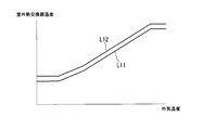
- FIG. 3 is a graph showing an example of the threshold value determined by the heat exchanger temperature threshold value determination unit 193.
- the horizontal axis in FIG. 3 indicates the outside air temperature, and the vertical axis indicates the outdoor heat exchanger temperature.
- Line L11 shows a heat exchanger 1st threshold value.
- the heat exchanger first threshold value is one of criteria for determining whether or not the defrosting operation is necessary during the operation in the defrosting operation mode.
- a line L12 indicates the outdoor heat exchanger second threshold value.
- the heat exchanger temperature threshold value determination unit 193 sets the heat exchanger second threshold value to a temperature higher than the heat exchanger first threshold value.
- the operation control unit 194 causes the air conditioning system main body 200 to perform an operation for avoiding the defrosting operation based on the heat exchanger second threshold value
- the outdoor heat exchanger temperature is higher than the heat exchanger first threshold value. This is to make it higher.
- the heat exchanger temperature threshold value determination part 193 determines a heat exchanger 1st threshold value and a heat exchanger 2nd threshold value based on external temperature. When the outdoor temperature is low, the outdoor heat exchanger 12 is less likely to be frosted than when the outdoor temperature is high.
- the heat exchanger temperature threshold value determination unit 193 sets the heat exchanger first threshold value and the heat exchanger second threshold value lower than when the outside air temperature is high.
- FIG. 3 the example in case a heat exchanger 2nd threshold value is constant temperature higher than a heat exchanger 1st threshold value is shown. An example of this constant temperature is 2 ° C.
- the relationship between the heat exchanger first threshold and the heat exchanger second threshold is not limited thereto.
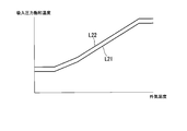
- FIG. 4 is a graph illustrating an example of threshold values determined by the saturation temperature threshold value determination unit 192.
- the horizontal axis in FIG. 4 indicates the outside air temperature, and the vertical axis indicates the suction pressure saturation temperature.
- a line L21 indicates the saturation temperature first threshold value.
- the saturation temperature first threshold value is one of criteria for determining whether or not the defrosting operation is necessary during the operation in the defrosting operation mode.
- a line L22 indicates the saturation temperature second threshold value.
- the saturation temperature second threshold value is one of the criteria for determining whether or not an operation for avoiding the defrosting operation is required during the operation in the defrosting operation avoiding mode.
- the saturation temperature threshold value determination unit 192 sets the saturation temperature second threshold value to a temperature higher than the saturation temperature first threshold value.
- the operation control unit 194 causes the air conditioning system main body 200 to perform an operation for avoiding the defrosting operation based on the saturation temperature second threshold, the suction pressure saturation temperature becomes higher than the saturation temperature first threshold. It is to do.
- the saturation temperature threshold value determination part 192 determines a saturation temperature 1st threshold value and a saturation temperature 2nd threshold value based on external temperature. When the outdoor temperature is low, the outdoor heat exchanger 12 is less likely to be frosted than when the outdoor temperature is high.
- the heat exchanger temperature threshold value determination unit 193 sets the saturation temperature first threshold value and the saturation temperature second threshold value lower than when the outside air temperature is high.
- FIG. 4 shows an example in which the saturation temperature second threshold is higher than the saturation temperature first threshold by a certain temperature.
- An example of this constant temperature is 2 ° C.
- the relationship between the saturation temperature first threshold and the saturation temperature second threshold is not limited thereto.
- the operation control unit 194 includes a case where the suction pressure saturation temperature is lower than the saturation temperature second threshold and a case where the temperature of the outdoor heat exchanger 12 is lower than the heat exchanger second threshold. In either case, the air conditioning system main body 200 performs an operation for avoiding the defrosting operation. In the defrosting operation mode, the operation control unit 194 includes any of the case where the suction pressure saturation temperature is lower than the saturation temperature first threshold and the case where the temperature of the outdoor heat exchanger 12 is lower than the heat exchanger first threshold. Also, the air conditioning system main body 200 is caused to perform a defrosting operation.
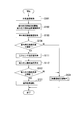
- FIG. 5 is a flowchart showing a processing procedure in which the control device 100 controls the air conditioning system main body 200 during the heating operation in the defrosting operation avoidance mode.
- the sensor value acquisition unit 110 acquires the outside temperature detected by the outside temperature sensor 23 (step S101).
- the saturation temperature threshold value determination unit 192 determines the saturation temperature first threshold value and the saturation temperature second threshold value based on the outside air temperature
- the heat exchanger temperature threshold value determination unit 193 determines the heat exchanger first value based on the outside air temperature.
- a threshold value and a heat exchanger second threshold value are determined (step S102).
- the sensor value acquisition part 110 acquires the outdoor heat exchanger temperature which the outdoor heat exchanger temperature sensor 22 detected (step S103). And the operation control part 194 determines whether outdoor heat exchanger temperature is more than a heat exchanger 2nd threshold value (step S104). When it determines with outdoor heat exchanger temperature being more than a heat exchanger 2nd threshold value (step S104: YES), the sensor value acquisition part 110 acquires the suction pressure of the compressor 15 which the pressure sensor 21 detected (step). S111).
- the saturation temperature calculation unit 191 calculates the suction pressure saturation temperature based on the suction pressure detected by the pressure sensor 21 (step S112). Then, the operation control unit 194 determines whether or not the suction pressure saturation temperature is equal to or higher than the suction pressure saturation temperature second value (step S113). When it is determined that the suction pressure saturation temperature is equal to or higher than the saturation temperature second threshold (step S113: YES), the operation control unit 194 controls the air conditioning system body 200 to perform a normal heating operation (step S121). . After step S121, the process in FIG.
- step S104 when it determines with outdoor heat exchanger temperature being less than a heat exchanger 2nd threshold value in step S104 (step S104: NO), the operation control part 194 controls the air conditioning system main body 200, and defrosts. An operation for avoiding driving is performed (step S131). After step S131, the process of FIG. On the other hand, if it is determined in step S113 that the suction pressure saturation temperature is less than the saturation temperature second threshold (step S113: NO), the process proceeds to step S131. As described above, in step S104 and step S113, the operation control unit 194 determines whether countermeasures against frost adhesion to the outdoor heat exchanger 12 are required based on the suction pressure saturation temperature and the temperature of the outdoor heat exchanger 12. Determine.
- FIG. 6 is a flowchart illustrating an example of a processing procedure in which the control device 100 causes the air conditioning system main body 200 to perform an operation for avoiding the defrosting operation.
- the operation control unit 194 calculates a rate of change per unit time of the outdoor heat exchanger temperature (step S201). Then, the operation control unit 194 indicates that the rate of change calculated in step S201 indicates a decrease in temperature, and the magnitude of the rate of change (decrease rate) is a predetermined rate of change threshold (the threshold of the rate of change of the outdoor heat exchanger temperature). ) It is determined whether or not this is the case (step S202).
- step S202 When it is determined that the rate of change indicates a decrease in temperature and the magnitude of the rate of change is greater than or equal to the rate of change threshold (step S202: YES), the operation control unit 194 opens the hot gas bypass valve 16 (step S211). ). Thereby, the refrigerant
- the operation control unit 194 includes the outdoor fan. It is determined whether the number of rotations 13 is less than the maximum number of rotations (step S221).
- the maximum rotational speed here is the maximum rotational speed determined by the specifications of the outdoor fan 13.
- the operation control part 194 increases the rotation speed of the outdoor fan 13 (step S231). As the rotational speed of the outdoor fan increases, the amount of refrigerant evaporated in the outdoor heat exchanger 12 increases, the pressure rises, and the temperature of the outdoor heat exchanger 12 rises. After step S231, the process of FIG.
- step S221 NO
- the operation control part 194 reduces the rotation speed of the compressor 15 (step S241). As the rotational speed of the compressor 15 decreases, the circulation amount of the refrigerant decreases and the temperature of the outdoor heat exchanger 12 rises. After step S241, the process of FIG. When the hot gas bypass valve 16 is opened in step S221, the operation control unit 194 closes the hot gas bypass valve 16 when performing the normal heating operation in step S121 of FIG.
- PI control Proportion-Integral Control
- the operation control unit 194 when it is determined that the suction pressure saturation temperature is lower than the saturation temperature second threshold, the operation control unit 194 performs PI control that brings the suction pressure saturation temperature closer to the saturation temperature second threshold.
- the administrator of the air conditioning system 1 obtains a control gain in which the suction pressure saturation temperature does not become less than the saturation temperature first threshold value in advance by a test operation or the like as a control gain in this case, and sets the control gain in the control device 100.
- the operation control part 194 when it determines with outdoor heat exchanger temperature being less than a heat exchanger 2nd threshold value, the operation control part 194 performs PI control which brings outdoor heat exchanger temperature close to a heat exchanger 2nd threshold value.
- the manager of the air conditioning system 1 obtains in advance a control gain in which the outdoor heat exchanger temperature does not become less than the first heat exchanger threshold value as a control gain in this case, and sets the control gain in the control device 100.
- the control method in which the operation control unit 194 increases the rotation speed of the outdoor fan 13 in step S221 and the control method in which the operation control unit 194 decreases the rotation speed of the compressor 15 in step S241 are not limited to PI control. .
- the suction pressure saturation temperature is the saturation temperature. Any control method may be used as long as it does not fall below the first threshold and the outdoor heat exchanger temperature does not fall below the first heat exchanger threshold.
- FIG. 7 is a schematic configuration diagram showing a configuration example of an outdoor heat exchanger in a multi-circuit type outdoor unit.
- the heat exchanger system 19 includes a first distributor 210, a first expansion valve 221, a second expansion valve 222, a second distributor 231, and a third distributor 232.
- the first pipe W11 is branched by the first distributor 210 into a pipe W221 and a pipe W222.
- the first distributor 210 and the first expansion valve 221 are connected by a pipe W221.
- the first distributor 210 and the second expansion valve 222 are connected by a pipe W222.
- the first expansion valve 221 and the second distributor 231 are connected by a pipe W231.
- the second expansion valve 222 and the third distributor 232 are connected by a pipe W232.
- the pipe W231 is branched into 17 pipes W241-1 to W241-17 by the second distributor 231.
- the pipe W241-1 reaches the second pipe W12 via the first outdoor heat exchanger 241.
- the pipe W241-2,..., The pipe W241-17 also reach the second pipe W12 via the first outdoor heat exchanger 241.
- the pipe W232 is branched into 17 pipes W242-1 to W242-17 by the third distributor 232.
- the pipe W242-1 reaches the second pipe W12 via the second outdoor heat exchanger 242.
- the pipes W242-2,..., The pipe W242-17 also reach the second pipe W12 via the second outdoor heat exchanger 242, respectively.
- 17 circuits are provided in each of the first outdoor heat exchanger 241 and the second outdoor heat exchanger 242.
- the circuit here is a path formed by piping.
- the 17 circuits provided in the heat exchanger 241 outside the first chamber each include any one of the pipes W241-1 to W241-17.
- the 17 circuits provided in the heat exchanger 242 outside the second chamber each include any one of pipes W242-1 to W242-17.
- an outdoor heat exchanger having a plurality of circuits may be used.
- the number of outdoor heat exchangers provided in the heat exchanger system 19 is not limited to two (the first outdoor heat exchanger 241 and the second outdoor heat exchanger 242) illustrated in FIG. 7 and may be one or more.
- the number of circuits provided in the outdoor heat exchanger is not limited to 17 per outdoor heat exchanger shown in FIG. 7, but may be two or more.
- a first outdoor heat exchanger temperature sensor 251 is provided in the pipe W241-4 as a representative of the pipes W241-1 to W241-17.
- a second outdoor heat exchanger temperature sensor 252 is provided in the pipe W242-4 as a representative of the pipes W242-1 to W242-17.
- the temperature of each pipe may vary. For example, if the refrigerant distribution amount to the pipes W241-1 to W241-17 varies due to the accuracy of the second distributor 231, the temperature of each pipe varies. Also, the temperature of each pipe varies due to the influence of the wind hitting the outdoor heat exchanger. This applies to both the first outdoor heat exchanger 241 and the second outdoor heat exchanger 242.
- the outdoor heat exchanger temperature sensors referred to here are the first outdoor heat exchanger temperature sensor 251 and the second outdoor heat exchanger temperature sensor 252.
- the temperature of the piping other than the piping to which the outdoor heat exchanger temperature sensor is attached may be the lowest.
- the distributors here are the second distributor 231 and the third distributor 232.
- control device 100 does not have a function of avoiding frost adhesion based on the suction pressure saturation temperature. In this case, even if frost adheres to a pipe other than the pipe to which the outdoor heat exchanger temperature sensor is attached, the control device 100 cannot detect the attachment of the frost, and the capacity of the air conditioning system 1 is reduced. Damage to the heat exchanger and refrigerant leakage may occur.
- the operation control unit 194 causes the air conditioning system main body 200 to perform an operation for avoiding the defrosting operation based on the suction pressure saturation temperature.
- the operation control unit 194 causes the air conditioning system main body 200 to perform an operation for avoiding the defrosting operation.
- coolant leakage by ice becomes high.
- a pressure sensor is often provided to detect the suction pressure of the compressor.
- the pressure sensor 21 for detecting the suction pressure of the compressor 15 can be used for the operation for avoiding the defrosting operation, and for determining whether the operation for avoiding the defrosting operation is necessary. There is no need to use a new pressure sensor.
- the operation control unit 194 determines whether it is necessary to take measures against frost adhesion on the outdoor heat exchanger 12 based on the suction pressure saturation temperature and the temperature of the outdoor heat exchanger 12. Thereby, the operation control part 194 can raise determination accuracy rather than the case where the necessity of a countermeasure is determined only by the temperature of the outdoor heat exchanger 12.
- the measure here may be a measure for removing frost adhering to the outdoor heat exchanger 12 as in the defrosting operation, or to the outdoor heat exchanger 12 as an operation for avoiding the defrosting operation. It may be a measure for preventing frost adhesion.
- the operation control unit 194 controls the air conditioning system main body 200 to set the temperature of the outdoor heat exchanger 12 to be equal to or higher than the heat exchanger first threshold and to set the suction pressure saturation temperature to be equal to or higher than the saturation temperature first threshold.
- the air conditioning system 1 can prevent the adhesion of frost to the outdoor heat exchanger 12, and can avoid the defrosting operation.
- the air conditioning system 1 can continue the heating operation while avoiding the interruption of the heating operation due to the defrosting operation.
- the operation control unit 194 increases the suction pressure saturation temperature by opening the hot gas bypass valve 16.
- the air conditioning system 1 can raise the temperature of the outdoor heat exchanger 12, and can perform the frosting countermeasure which removes or prevents the adhesion of the frost to the outdoor heat exchanger 12.
- the operation control unit 194 increases the rotational speed of the outdoor fan 13.
- the air conditioning system 1 can raise the temperature of the outdoor heat exchanger 12, and can perform the frosting countermeasure which removes or prevents the adhesion of the frost to the outdoor heat exchanger 12.
- the operation control unit 194 increases the suction pressure saturation temperature by decreasing the rotational speed of the compressor 15. Thereby, the air conditioning system 1 can raise the temperature of the outdoor heat exchanger 12, and can perform the frosting countermeasure which removes or prevents the adhesion of the frost to the outdoor heat exchanger 12.
- a program for realizing all or a part of the functions of the control device 100 is recorded on a computer-readable recording medium, and the program recorded on the recording medium is read into the computer system and executed to execute processing of each unit. May be performed.
- the “computer system” here includes an OS and hardware such as peripheral devices.
- the “computer-readable recording medium” refers to a storage device such as a flexible medium, a magneto-optical disk, a portable medium such as a ROM or a CD-ROM, and a hard disk incorporated in a computer system.
- the program may be a program for realizing a part of the functions described above, and may be a program capable of realizing the functions described above in combination with a program already recorded in a computer system.
- Embodiments of the present invention include a compressor that compresses a gaseous refrigerant, an indoor heat exchanger that liquefies the compressed gaseous refrigerant and dissipates the heat of condensation, and absorbs the heat of vaporization to vaporize the liquid refrigerant.
- An air conditioning system main body comprising: an outdoor heat exchanger; a pressure sensor that detects a suction pressure of refrigerant into the compressor; and an outdoor heat exchanger temperature sensor that detects a temperature of the outdoor heat exchanger; Based on the saturation temperature calculation unit for calculating the suction pressure saturation temperature from the pressure, the suction pressure saturation temperature, and the temperature of the outdoor heat exchanger, whether or not countermeasures against the adhesion of frost to the outdoor heat exchanger are determined. And an operation control unit for determination. According to this embodiment, it is possible to improve the determination accuracy of the necessity of countermeasures against frost adhesion.
- Control apparatus 110 Sensor value acquisition part 120 Control signal transmission part 180 Storage part 190 Control part 191 Saturation temperature calculation part 192 Saturation temperature threshold value determination part 193 Heat exchanger temperature threshold value determination part 194 Operation control part
Landscapes
- Engineering & Computer Science (AREA)
- Mechanical Engineering (AREA)
- General Engineering & Computer Science (AREA)
- Physics & Mathematics (AREA)
- Thermal Sciences (AREA)
- Chemical & Material Sciences (AREA)
- Combustion & Propulsion (AREA)
- Air Conditioning Control Device (AREA)
Abstract
空気調和システムが、気体の冷媒を圧縮する圧縮機と、圧縮された気体の冷媒を液化させて凝縮熱を放熱する室内熱交換器と、気化熱を吸熱して液体の冷媒を気化させる室外熱交換器と、前記圧縮機への冷媒の吸入圧力を検出する圧力センサと、前記室外熱交換器の温度を検出する室外熱交換器温度センサと、を備える空気調和システム本体と、前記吸入圧力から吸入圧力飽和温度を算出する飽和温度算出部と、前記吸入圧力飽和温度と、前記室外熱交換器の温度とに基づいて、前記室外熱交換器への霜の付着に対する対策の要否を判定する運転制御部と、を備える。
Description
本発明は、空気調和システム、制御方法及びプログラムに関する。
本願は、2015年7月1日に、日本国に出願された特願2015-133048号に基づき優先権を主張し、その内容をここに援用する。
本願は、2015年7月1日に、日本国に出願された特願2015-133048号に基づき優先権を主張し、その内容をここに援用する。
空気調和システムの暖房運転時に外気温度が低下して室外熱交換器に霜が付着する場合がある。この場合、付着した霜を溶かすために空気調和システムが除霜運転(Defrosting Operation)を行うことがある。除霜運転では、空気調和システムが冷房サイクルにて運転を行うため、暖房運転は休止となる。
除霜運転に関連して、特許文献1には、暖房能力を抑制して運転することで室外機への霜の付着を遅らせる暖房連続運転優先モードを備える空気調和器が記載されている。この空気調和器は、室外熱交換器の冷媒配管に取り付けられた室外熱交換器配管温度検出センサで配管温度を検出する。配管温度が所定の連続運転液管温度閾値以上である場合、この空気調和器は、通常の暖房運転を行う。一方、配管温度が連続運転液管温度閾値を下回ると、この空気調和器は、室内機の吹き出し温度を低下させることで、除霜運転に入るまでの時間を長くする。配管温度がさらに低下して所定の霜取開始温度を下回ると、この空気調和器は、除霜運転を行う。
除霜運転に関連して、特許文献1には、暖房能力を抑制して運転することで室外機への霜の付着を遅らせる暖房連続運転優先モードを備える空気調和器が記載されている。この空気調和器は、室外熱交換器の冷媒配管に取り付けられた室外熱交換器配管温度検出センサで配管温度を検出する。配管温度が所定の連続運転液管温度閾値以上である場合、この空気調和器は、通常の暖房運転を行う。一方、配管温度が連続運転液管温度閾値を下回ると、この空気調和器は、室内機の吹き出し温度を低下させることで、除霜運転に入るまでの時間を長くする。配管温度がさらに低下して所定の霜取開始温度を下回ると、この空気調和器は、除霜運転を行う。
室外熱交換器に設置した温度センサを用いて、室外熱交換器への霜の付着に対する対策の要否を判定する場合、室外熱交換器の異なる箇所における温度分布にばらつきがあると、霜の付着に対する対策の要否の判定精度が低下する可能性がある。例えば、温度センサを設置した箇所よりも温度が低い個所があって霜が付着した場合に、対策不要と誤判定する可能性がある。
また、温度センサの故障等によって温度測定精度が低下した場合も、霜の付着に対する対策の要否の判定精度が低下する。
また、温度センサの故障等によって温度測定精度が低下した場合も、霜の付着に対する対策の要否の判定精度が低下する。
本発明は、霜の付着に対する対策の要否の判定精度を高めることができる空気調和システム、制御方法及びプログラムを提供する。
本発明の第1の態様によれば、空気調和システムは、気体の冷媒を圧縮する圧縮機と、圧縮された気体の冷媒を液化させて凝縮熱を放熱する室内熱交換器と、気化熱を吸熱して液体の冷媒を気化させる室外熱交換器と、前記圧縮機への冷媒の吸入圧力を検出する圧力センサと、前記室外熱交換器の温度を検出する室外熱交換器温度センサと、を備える空気調和システム本体と、前記吸入圧力から吸入圧力飽和温度を算出する飽和温度算出部と、前記吸入圧力飽和温度と、前記室外熱交換器の温度とに基づいて、前記室外熱交換器への霜の付着に対する対策の要否を判定する運転制御部と、を備える。
前記空気調和システム本体は、前記空気調和システム本体は、外気温度を検出する外気温度センサをさらに備え、前記空気調和システムは、前記外気温度に基づいて吸入圧力飽和温度の閾値を決定する飽和温度閾値決定部と、前記外気温度に基づいて室外熱交換器温度の閾値を決定する熱交換器温度閾値決定部と、をさらに備え、前記運転制御部は、前記室外熱交換器の温度を前記室外熱交換器温度の閾値以上に制御し、かつ、前記吸入圧力飽和温度を前記吸入圧力飽和温度の閾値以上に制御するようにしてもよい。
前記空気調和システム本体は、前記圧縮機が圧縮した冷媒を前記室外熱交換器へバイパスするホットガスバイパスに設けられたホットガスバイパス弁をさらに備え、前記運転制御部は、前記ホットガスバイパス弁を開くことで、前記室外熱交換器の温度を前記室外熱交換器温度の閾値以上に制御し、かつ、前記吸入圧力飽和温度を前記吸入圧力飽和温度の閾値以上に制御するようにしてもよい。
前記空気調和システム本体は、外気を前記室外熱交換器に送風する室外ファンをさらに備え、前記運転制御部は、前記室外ファンの回転数を増加させることで、前記室外熱交換器の温度を前記室外熱交換器温度の閾値以上に制御し、かつ、前記吸入圧力飽和温度を前記吸入圧力飽和温度の閾値以上に制御するようにしてもよい。
前記運転制御部は、前記圧縮機の回転数を減少させることで、前記室外熱交換器の温度を前記室外熱交換器温度の閾値以上に制御し、かつ、前記吸入圧力飽和温度を前記吸入圧力飽和温度の閾値以上に制御するようにしてもよい。
本発明の第2の態様によれば、制御方法は、気体の冷媒を圧縮する圧縮機と、圧縮された気体の冷媒を液化させて凝縮熱を放熱する室内熱交換器と、気化熱を吸熱して液体の冷媒を気化させる室外熱交換器と、前記圧縮機への冷媒の吸入圧力を検出する圧力センサと、前記室外熱交換器の温度を検出する室外熱交換器温度センサと、を備える空気調和システム本体を制御する制御方法であって、前記吸入圧力から吸入圧力飽和温度を算出し、前記吸入圧力飽和温度と、前記室外熱交換器の温度とに基づいて、前記室外熱交換器への霜の付着に対する対策の要否を判定する制御方法である。
本発明の第3の態様によれば、プログラムは、気体の冷媒を圧縮する圧縮機と、圧縮された気体の冷媒を液化させて凝縮熱を放熱する室内熱交換器と、気化熱を吸熱して液体の冷媒を気化させる室外熱交換器と、前記圧縮機への冷媒の吸入圧力を検出する圧力センサと、前記室外熱交換器の温度を検出する室外熱交換器温度センサと、を備える空気調和システム本体を制御するコンピュータに、前記吸入圧力から吸入圧力飽和温度を算出させ、前記吸入圧力飽和温度と、前記室外熱交換器の温度とに基づいて、前記室外熱交換器への霜の付着に対する対策の要否を判定させるためのプログラムである。
上記した空気調和システム、制御方法及びプログラムによれば、霜の付着に対する対策の要否の判定精度を高めることができる。
以下、本発明の実施形態を説明するが、以下の実施形態は請求の範囲にかかる発明を限定するものではない。また、実施形態の中で説明されている特徴の組み合わせの全てが発明の解決手段に必須であるとは限らない。
図1は、本発明の実施形態に係る空気調和システムの概略構成図である。図1に示すように、空気調和システム1は、室外機2と、室内機3とを備える。室外機2は、膨張弁11と、室外熱交換器12と、室外ファン13と、四方弁14と、圧縮機15と、ホットガスバイパス弁16と、圧力センサ21と、室外熱交換器温度センサ22と、外気温度センサ23と、制御装置100とを備える。室内機3は、室内熱交換器31と、室内ファン32とを備える。
空気調和システム1のうち、制御装置100以外の各部を総称して空気調和システム本体200と称する。制御装置100は、空気調和システム本体200を制御する。
図1は、本発明の実施形態に係る空気調和システムの概略構成図である。図1に示すように、空気調和システム1は、室外機2と、室内機3とを備える。室外機2は、膨張弁11と、室外熱交換器12と、室外ファン13と、四方弁14と、圧縮機15と、ホットガスバイパス弁16と、圧力センサ21と、室外熱交換器温度センサ22と、外気温度センサ23と、制御装置100とを備える。室内機3は、室内熱交換器31と、室内ファン32とを備える。
空気調和システム1のうち、制御装置100以外の各部を総称して空気調和システム本体200と称する。制御装置100は、空気調和システム本体200を制御する。
膨張弁11と室外熱交換器12とは第1配管W11で接続されている。室外熱交換器12と四方弁14とは、第2配管W12で接続されている。四方弁14と圧縮機15とは第3配管W13で接続されており、第3配管W13に圧力センサ21が設けられている。圧縮機15と室内熱交換器31とは第4配管W14で接続されている。第4配管W14と第1配管W11とが第5配管W15で接続されており、第5配管W15は、圧縮機15が圧縮した冷媒の一部を第1配管W11へ逃がすホットガスバイパス弁を構成している。第5配管W15にはホットガスバイパス弁16が設けられている。四方弁14と室内熱交換器31とは第6配管W21で接続されている。室内熱交換器31と膨張弁11とは第7配管W22で接続されている。
空気調和システム1が備える室内熱交換器31の数は同図に示す2つに限らず1つ以上であればよい。
空気調和システム1が備える室内熱交換器31の数は同図に示す2つに限らず1つ以上であればよい。
空気調和システム1は、室内の空気の温度を調整するシステムである。空気調和システム1では、暖房運転と冷房運転とを切り替え可能である。また、空気調和システム1では、暖房運転時に、除霜運転を行う除霜運転モードと除霜運転を回避する除霜運転回避モードとを切り替え可能である。
暖房運転では、圧縮機15で圧縮された気体の冷媒が、第4配管W14、四方弁14、第6配管W21の順に経由して室内熱交換器31へ流入する。室内熱交換器31へ流入した気体の冷媒は、室内の空気との熱交換によって放熱して凝縮する。凝縮によって液体になった冷媒は、第7配管W22を経由して膨張弁11で減圧された後、さらに第1配管W11を経由して室外熱交換器12へ流入する。室外熱交換器12へ流入した冷媒は、外気との熱交換によって吸熱して蒸発する。ここでいう外気は、室外の空気である。蒸発によって気体になった冷媒は、第2配管W12、四方弁14、第3配管W13の順に経由して圧縮機15へ流入し圧縮される。
暖房運転では、圧縮機15で圧縮された気体の冷媒が、第4配管W14、四方弁14、第6配管W21の順に経由して室内熱交換器31へ流入する。室内熱交換器31へ流入した気体の冷媒は、室内の空気との熱交換によって放熱して凝縮する。凝縮によって液体になった冷媒は、第7配管W22を経由して膨張弁11で減圧された後、さらに第1配管W11を経由して室外熱交換器12へ流入する。室外熱交換器12へ流入した冷媒は、外気との熱交換によって吸熱して蒸発する。ここでいう外気は、室外の空気である。蒸発によって気体になった冷媒は、第2配管W12、四方弁14、第3配管W13の順に経由して圧縮機15へ流入し圧縮される。
一方、冷房運転では、圧縮機15で圧縮された気体の冷媒が、第4配管W14、四方弁14、第2配管W12の順に経由して室外熱交換器12へ流入する。室外熱交換器12へ流入した気体の冷媒は、外気との熱交換によって放熱して凝縮する。凝縮によって液体になった冷媒は、第1配管W11を経由して膨張弁11で減圧された後、第7配管W22を経由して室内熱交換器31へ流入する。室内熱交換器31へ流入した冷媒は、室内の空気との熱交換によって吸熱して蒸発する。蒸発によって気体になった冷媒は、第6配管W21、四方弁14、第3配管W13の順に経由して圧縮機15へ流入し圧縮される。
除霜運転でも、冷媒は暖房運転の場合と同様に流れ、室外熱交換器12で放熱することで室外熱交換器12を加熱する。この加熱によって室外熱交換器12に付着している霜が溶ける。
除霜運転でも、冷媒は暖房運転の場合と同様に流れ、室外熱交換器12で放熱することで室外熱交換器12を加熱する。この加熱によって室外熱交換器12に付着している霜が溶ける。
室外機2は、例えば室外など外気との熱交換が可能な場所に設置される。
膨張弁11は、膨張弁11自らを流れる液体の冷媒を減圧する。この減圧により冷媒が蒸発し易くなる。
室外熱交換器12は、冷媒と外気との間で熱交換を行わせる。暖房運転では、膨張弁11で減圧された低圧の液体の冷媒が室外熱交換器12へ流入し、外気との熱交換によって吸熱して蒸発する。従って、室外熱交換器12は、外気から気化熱を吸熱して液体の冷媒を気化させる。一方、冷房運転では、圧縮機15で圧縮された高圧の気体の冷媒が室外熱交換器12へ流入し、外気との熱交換によって放熱して凝縮する。
室外ファン13は、外気を室外熱交換器12に送風する。室外ファンの送風により室外熱交換器12での熱交換が促進される。
膨張弁11は、膨張弁11自らを流れる液体の冷媒を減圧する。この減圧により冷媒が蒸発し易くなる。
室外熱交換器12は、冷媒と外気との間で熱交換を行わせる。暖房運転では、膨張弁11で減圧された低圧の液体の冷媒が室外熱交換器12へ流入し、外気との熱交換によって吸熱して蒸発する。従って、室外熱交換器12は、外気から気化熱を吸熱して液体の冷媒を気化させる。一方、冷房運転では、圧縮機15で圧縮された高圧の気体の冷媒が室外熱交換器12へ流入し、外気との熱交換によって放熱して凝縮する。
室外ファン13は、外気を室外熱交換器12に送風する。室外ファンの送風により室外熱交換器12での熱交換が促進される。
四方弁14は、冷媒の流路を切り替えることで暖房運転、冷房運転、除霜運転の切替を行う。暖房運転では、四方弁14が、第4配管W14と第6配管W21とを接続することで圧縮機15からの冷媒を室内熱交換器31へ流入させる。また、暖房運転では、四方弁14が、第2配管W12と第3配管W13とを接続することで室外熱交換器12からの冷媒を圧縮機15へ流入させる。一方、冷房運転及び除霜運転では、四方弁14が、第4配管W14と第2配管W12とを接続することで圧縮機15からの冷媒を室外熱交換器12へ流入させる。また、冷房運転及び除霜運転では、四方弁14が、第6配管W21と第3配管W13とを接続することで室内熱交換器31からの冷媒を圧縮機15へ流入させる。
圧縮機15は、気体の冷媒を圧縮する。
ホットガスバイパス弁16は、圧縮機15から第1配管W11への冷媒の流れの有無を切り替える。ホットガスバイパス弁16が開くと、圧縮機15が圧縮した冷媒の一部が第5配管W15を経由して第1配管W11へ流れる。一方、ホットガスバイパス弁16が閉じると、この流れが遮断される。
空気調和システムのうち、圧縮機が圧縮した冷媒の圧力が高くなりすぎた場合に冷媒を減圧して機器や配管を保護する目的でホットガスバイパス及びホットガスバイパス弁を備えるものがある。一方、本実施形態の空気調和システム1は、この目的に加えて、室外熱交換器12の除霜を行う目的でホットガスバイパス及びホットガスバイパス弁16を用いる。第5配管W15が、ホットガスバイパスの例に該当する。
圧力センサ21は、圧縮機15への冷媒の吸入圧力を検出する。
室外熱交換器温度センサ22は、室外熱交換器12の温度を検出する。例えば、室外熱交換器温度センサ22は、室外熱交換器12の冷媒配管の外面に設けられ、この配管の外面の温度を測定する。
外気温度センサ23は、外気温度を検出する。
膨張弁11、四方弁14、圧縮機15、ホットガスバイパス弁16、圧力センサ21、外気温度センサ23、制御装置100の何れか、または、これらのうち複数が、室外機2の外部に設けられていてもよい。
室外熱交換器温度センサ22は、室外熱交換器12の温度を検出する。例えば、室外熱交換器温度センサ22は、室外熱交換器12の冷媒配管の外面に設けられ、この配管の外面の温度を測定する。
外気温度センサ23は、外気温度を検出する。
膨張弁11、四方弁14、圧縮機15、ホットガスバイパス弁16、圧力センサ21、外気温度センサ23、制御装置100の何れか、または、これらのうち複数が、室外機2の外部に設けられていてもよい。
室内機3は、温度調整対象の室内に設置される。
室内熱交換器31は、冷媒と室内の空気との間で熱交換を行わせる。暖房運転では、高圧の気体の冷媒が室内熱交換器31へ流入し、室内の空気との熱交換によって放熱して凝縮する。従って、室内熱交換器31は、圧縮機15によって圧縮された気体の冷媒を液化させて、凝縮熱を室内の空気に放熱する。一方、冷房運転では、低圧の液体の冷媒が室内熱交換器31へ流入し、室内の空気との熱交換によって吸熱して蒸発する。
室内ファン32は、室内機3が設置された室内の空気を室内熱交換器31へ送風する。
室内ファン32の送風により室内熱交換器31での熱交換が促進される。
室内熱交換器31は、冷媒と室内の空気との間で熱交換を行わせる。暖房運転では、高圧の気体の冷媒が室内熱交換器31へ流入し、室内の空気との熱交換によって放熱して凝縮する。従って、室内熱交換器31は、圧縮機15によって圧縮された気体の冷媒を液化させて、凝縮熱を室内の空気に放熱する。一方、冷房運転では、低圧の液体の冷媒が室内熱交換器31へ流入し、室内の空気との熱交換によって吸熱して蒸発する。
室内ファン32は、室内機3が設置された室内の空気を室内熱交換器31へ送風する。
室内ファン32の送風により室内熱交換器31での熱交換が促進される。
制御装置100は、空気調和システム本体200を制御する。制御装置100は、例えばコンピュータを含んで構成される。
図2は、制御装置100の機能構成を示す概略ブロック図である。図2に示すように制御装置100は、センサ値取得部110と、制御信号送信部120と、記憶部180と、制御部190とを備える。制御部190は、飽和温度算出部(吸入圧力飽和温度算出部)191と、飽和温度閾値決定部(吸入圧力飽和温度閾値決定部)192と、熱交換器温度閾値決定部(室外熱交換器温度閾値決定部)193と、運転制御部194とを備える。
図2は、制御装置100の機能構成を示す概略ブロック図である。図2に示すように制御装置100は、センサ値取得部110と、制御信号送信部120と、記憶部180と、制御部190とを備える。制御部190は、飽和温度算出部(吸入圧力飽和温度算出部)191と、飽和温度閾値決定部(吸入圧力飽和温度閾値決定部)192と、熱交換器温度閾値決定部(室外熱交換器温度閾値決定部)193と、運転制御部194とを備える。
センサ値取得部110は、空気調和システム本体200に設けられた各センサからのセンサ値を取得する。特に、センサ値取得部110は、圧力センサ21が検出する吸入圧力、室外熱交換器温度センサ22が検出する室外熱交換器12の温度、及び、外気温度センサ23が検出する外気温度を取得する。
制御信号送信部120は、制御部190が生成する制御信号を空気調和システム本体200へ送信する。
記憶部180は、制御装置100が備える記憶デバイスを用いて構成され、各種データを記憶する。
制御信号送信部120は、制御部190が生成する制御信号を空気調和システム本体200へ送信する。
記憶部180は、制御装置100が備える記憶デバイスを用いて構成され、各種データを記憶する。
制御部190は、制御装置100の各部を制御する。特に、制御部190は、空気調和システム本体200の各部を制御するための制御信号を運転制御部194にて生成する。制御部190は、生成した制御信号を、制御信号送信部120を介して空気調和システム本体200の各部へ送信する。
飽和温度算出部191は、圧力センサ21が検出する圧縮機15の吸入圧力から吸入圧力飽和温度を算出する。吸入圧力飽和温度は、圧縮機の吸入圧力に応じて定まる、この圧縮機での冷媒の飽和温度である。
飽和温度算出部191が算出する吸入圧力飽和温度は、室外熱交換器12の蒸発温度を近似的に示している。
飽和温度算出部191は、圧力センサ21が検出する圧縮機15の吸入圧力から吸入圧力飽和温度を算出する。吸入圧力飽和温度は、圧縮機の吸入圧力に応じて定まる、この圧縮機での冷媒の飽和温度である。
飽和温度算出部191が算出する吸入圧力飽和温度は、室外熱交換器12の蒸発温度を近似的に示している。
飽和温度閾値決定部192は、外気温度センサ23が検出する外気温度に基づいて吸入圧力飽和温度第1閾値(以下、「飽和温度第1閾値」と称する場合がある)及び吸入圧力飽和温度第2閾値(以下、「飽和温度第2閾値」と称する場合がある)を決定する。
飽和温度第1閾値は、吸入圧力飽和温度の閾値の例に該当する。これらの閾値については後述する。
熱交換器温度閾値決定部193は、外気温度センサ23が検出する外気温度に基づいて室外熱交換器温度の第1閾値(以下、「熱交換器第1閾値」と称する場合がある)と、室外熱交換器温度の第2閾値(以下、「熱交換器第2閾値」と称する場合がある)とを決定する。熱交換器第1閾値は、室外熱交換器温度の閾値の例に該当する。これらの閾値については後述する。
飽和温度第1閾値は、吸入圧力飽和温度の閾値の例に該当する。これらの閾値については後述する。
熱交換器温度閾値決定部193は、外気温度センサ23が検出する外気温度に基づいて室外熱交換器温度の第1閾値(以下、「熱交換器第1閾値」と称する場合がある)と、室外熱交換器温度の第2閾値(以下、「熱交換器第2閾値」と称する場合がある)とを決定する。熱交換器第1閾値は、室外熱交換器温度の閾値の例に該当する。これらの閾値については後述する。
運転制御部194は、空気調和システム本体200を制御するための制御信号を生成することで、空気調和システム本体200を制御する。特に、制御部190は、ユーザ操作に従って暖房運転又は冷房運転のいずれかを選択し、選択した運転を実行する。また、暖房運転時に制御部190は、ユーザ操作に従って除霜運転モード又は除霜運転回避モードいずれかを選択し、選択したモードでの運転を実行する。除霜運転モードでは、運転制御部194は、室外熱交換器12に霜が付着した場合に除霜運転を行う。除霜運転回避モードでは、運転制御部194は室外熱交換器12への霜の付着を回避するために、除霜運転回避のための動作として定められている動作を空気調和システム本体200に行わせる。除霜運転回避のための動作については後述する。
また、除霜運転回避モードが選択されている場合、運転制御部194は、暖房運転時に室外熱交換器12の温度が熱交換器第1閾値よりも低下せず、かつ、吸入圧力飽和温度が飽和温度第1閾値よりも低下しないように、空気調和システム本体200を制御する。
除霜運転回避モードでの運転時に室外熱交換器12の温度が熱交換器第1閾値に近付いた場合、及び、吸入圧力飽和温度が飽和温度第1閾値に近付いた場合のいずれも、運転制御部194は、除霜運転回避のための動作を空気調和システム本体200に行わせて、室外熱交換器12の温度、及び、吸入圧力飽和温度を上昇させる。
具体的には、運転制御部194は、室外熱交換器12の温度が熱交換器第2閾値より小さくなった場合、及び、吸入圧力飽和温度が飽和温度第2閾値より小さくなった場合のいずれも、除霜運転回避のための動作として以下のいずれか又はこれらの組み合わせを実行する。
除霜運転回避モードでの運転時に室外熱交換器12の温度が熱交換器第1閾値に近付いた場合、及び、吸入圧力飽和温度が飽和温度第1閾値に近付いた場合のいずれも、運転制御部194は、除霜運転回避のための動作を空気調和システム本体200に行わせて、室外熱交換器12の温度、及び、吸入圧力飽和温度を上昇させる。
具体的には、運転制御部194は、室外熱交換器12の温度が熱交換器第2閾値より小さくなった場合、及び、吸入圧力飽和温度が飽和温度第2閾値より小さくなった場合のいずれも、除霜運転回避のための動作として以下のいずれか又はこれらの組み合わせを実行する。
(1)ホットガスバイパス弁16を開く。
ホットガスバイパス弁16が開くことで、圧縮機15で圧縮された高温の冷媒が室外熱交換器12に流入し、室外熱交換器12の温度、及び、吸入圧力飽和温度が上昇する。
(2)室外ファン13の回転数を増加させる。
室外ファン13の回転数が増加することで、室外熱交換器12での熱交換が促進され単位時間当たりの冷媒の蒸発量が増加する。単位時間当たりの冷媒の蒸発量が増加することで室外熱交換器12内の圧力が上昇し、室外熱交換器12の温度、及び、吸入圧力飽和温度が上昇する。
(3)圧縮機15の回転数を減少させる。
圧縮機15の回転数が減少することで単位時間当たりに室外熱交換器12へ流入する冷媒の量が減少する。これにより、冷媒による室外熱交換器12の冷却が抑制され、室外熱交換器12の温度、及び、吸入圧力飽和温度が上昇する。
図3は、熱交換器温度閾値決定部193が決定する閾値の例を示すグラフである。
図3の横軸は外気温度を示し、縦軸は室外熱交換器温度を示す。線L11は、熱交換器第1閾値を示す。熱交換器第1閾値は、除霜運転モードでの運転時に、除霜運転の要否の判定基準の1つとなる。線L12は、室外熱交換器第2閾値を示す。室外熱交換器第2閾値は、除霜運転回避モードでの運転時に、除霜運転回避のための動作の要否の判定基準の1つとなる。
図3の横軸は外気温度を示し、縦軸は室外熱交換器温度を示す。線L11は、熱交換器第1閾値を示す。熱交換器第1閾値は、除霜運転モードでの運転時に、除霜運転の要否の判定基準の1つとなる。線L12は、室外熱交換器第2閾値を示す。室外熱交換器第2閾値は、除霜運転回避モードでの運転時に、除霜運転回避のための動作の要否の判定基準の1つとなる。
図3に示すように熱交換器温度閾値決定部193は、熱交換器第2閾値を熱交換器第1閾値よりも高い温度に設定する。運転制御部194が熱交換器第2閾値に基づいて空気調和システム本体200に、除霜運転回避のための動作を行わせた際に、室外熱交換器温度が熱交換器第1閾値よりも高くなるようにするためである。
また、図3に示すように熱交換器温度閾値決定部193は、外気温度に基づいて熱交換器第1閾値及び熱交換器第2閾値を決定する。外気温度が低い場合、外気温度が高い場合よりも室外熱交換器12に霜が付きにくくなる。そこで、熱交換器温度閾値決定部193は外気温度が高い場合よりも熱交換器第1閾値及び熱交換器第2閾値を低く設定する。
図3では、熱交換器第2閾値が熱交換器第1閾値よりも一定温度高い場合の例を示している。この一定温度の例として、2℃を挙げることができる。但し、熱交換器第1閾値と熱交換器第2閾値との関係はこれに限らない。
また、図3に示すように熱交換器温度閾値決定部193は、外気温度に基づいて熱交換器第1閾値及び熱交換器第2閾値を決定する。外気温度が低い場合、外気温度が高い場合よりも室外熱交換器12に霜が付きにくくなる。そこで、熱交換器温度閾値決定部193は外気温度が高い場合よりも熱交換器第1閾値及び熱交換器第2閾値を低く設定する。
図3では、熱交換器第2閾値が熱交換器第1閾値よりも一定温度高い場合の例を示している。この一定温度の例として、2℃を挙げることができる。但し、熱交換器第1閾値と熱交換器第2閾値との関係はこれに限らない。
図4は、飽和温度閾値決定部192が決定する閾値の例を示すグラフである。
図4の横軸は外気温度を示し、縦軸は吸入圧力飽和温度を示す。線L21は、飽和温度第1閾値を示す。飽和温度第1閾値は、除霜運転モードでの運転時に、除霜運転の要否の判定基準の1つとなる。線L22は、飽和温度第2閾値を示す。飽和温度第2閾値は、除霜運転回避モードでの運転時に、除霜運転回避のための動作の要否の判定基準の1つとなる。
図4の横軸は外気温度を示し、縦軸は吸入圧力飽和温度を示す。線L21は、飽和温度第1閾値を示す。飽和温度第1閾値は、除霜運転モードでの運転時に、除霜運転の要否の判定基準の1つとなる。線L22は、飽和温度第2閾値を示す。飽和温度第2閾値は、除霜運転回避モードでの運転時に、除霜運転回避のための動作の要否の判定基準の1つとなる。
図4に示すように飽和温度閾値決定部192は、飽和温度第2閾値を飽和温度第1閾値よりも高い温度に設定する。運転制御部194が飽和温度第2閾値に基づいて空気調和システム本体200に除霜運転回避のための動作を行わせた際に、吸入圧力飽和温度が飽和温度第1閾値よりも高くなるようにするためである。
また、図4に示すように飽和温度閾値決定部192は、外気温度に基づいて飽和温度第1閾値及び飽和温度第2閾値を決定する。外気温度が低い場合、外気温度が高い場合よりも室外熱交換器12に霜が付きにくくなる。そこで、熱交換器温度閾値決定部193は外気温度が高い場合よりも飽和温度第1閾値及び飽和温度第2閾値を低く設定する。
図4では、飽和温度第2閾値が飽和温度第1閾値よりも一定温度高い場合の例を示している。この一定温度の例として2℃を挙げることができる。但し、飽和温度第1閾値と飽和温度第2閾値との関係はこれに限らない。
また、図4に示すように飽和温度閾値決定部192は、外気温度に基づいて飽和温度第1閾値及び飽和温度第2閾値を決定する。外気温度が低い場合、外気温度が高い場合よりも室外熱交換器12に霜が付きにくくなる。そこで、熱交換器温度閾値決定部193は外気温度が高い場合よりも飽和温度第1閾値及び飽和温度第2閾値を低く設定する。
図4では、飽和温度第2閾値が飽和温度第1閾値よりも一定温度高い場合の例を示している。この一定温度の例として2℃を挙げることができる。但し、飽和温度第1閾値と飽和温度第2閾値との関係はこれに限らない。
運転制御部194は、除霜運転回避モードでは、吸入圧力飽和温度が飽和温度第2閾値より低下した場合、及び、室外熱交換器12の温度が熱交換器第2閾値よりも低下した場合のいずれも、空気調和システム本体200に除霜運転回避のための動作を行わせる。
運転制御部194は、除霜運転モードでは、吸入圧力飽和温度が飽和温度第1閾値より低下した場合、及び、室外熱交換器12の温度が熱交換器第1閾値よりも低下した場合のいずれも、空気調和システム本体200に除霜運転を行わせる。
運転制御部194は、除霜運転モードでは、吸入圧力飽和温度が飽和温度第1閾値より低下した場合、及び、室外熱交換器12の温度が熱交換器第1閾値よりも低下した場合のいずれも、空気調和システム本体200に除霜運転を行わせる。
図5は、除霜運転回避モードでの暖房運転時に制御装置100が空気調和システム本体200を制御する処理手順を示すフローチャートである。
図5の処理にて、センサ値取得部110は、外気温度センサ23が検出した外気温度を取得する(ステップS101)。
そして、飽和温度閾値決定部192は、外気温度に基づいて飽和温度第1閾値及び飽和温度第2閾値を決定し、熱交換器温度閾値決定部193は、外気温度に基づいて熱交換器第1閾値及び熱交換器第2閾値を決定する(ステップS102)。
図5の処理にて、センサ値取得部110は、外気温度センサ23が検出した外気温度を取得する(ステップS101)。
そして、飽和温度閾値決定部192は、外気温度に基づいて飽和温度第1閾値及び飽和温度第2閾値を決定し、熱交換器温度閾値決定部193は、外気温度に基づいて熱交換器第1閾値及び熱交換器第2閾値を決定する(ステップS102)。
また、センサ値取得部110は、室外熱交換器温度センサ22が検出した室外熱交換器温度を取得する(ステップS103)。
そして、運転制御部194は、室外熱交換器温度が熱交換器第2閾値以上か否かを判定する(ステップS104)。室外熱交換器温度が熱交換器第2閾値以上であると判定した場合(ステップS104:YES)、センサ値取得部110は、圧力センサ21が検出した圧縮機15の吸入圧力を取得する(ステップS111)。
そして、運転制御部194は、室外熱交換器温度が熱交換器第2閾値以上か否かを判定する(ステップS104)。室外熱交換器温度が熱交換器第2閾値以上であると判定した場合(ステップS104:YES)、センサ値取得部110は、圧力センサ21が検出した圧縮機15の吸入圧力を取得する(ステップS111)。
次に、飽和温度算出部191は、圧力センサ21が検出した吸入圧力に基づいて、吸入圧力飽和温度を算出する(ステップS112)。
そして、運転制御部194は、吸入圧力飽和温度が吸入圧力飽和温度第2値以上か否かを判定する(ステップS113)。吸入圧力飽和温度が飽和温度第2閾値以上であると判定した場合(ステップS113:YES)、運転制御部194は、空気調和システム本体200を制御して通常の暖房運転を行わせる(ステップS121)。
ステップS121の後、図5の処理を終了する。
そして、運転制御部194は、吸入圧力飽和温度が吸入圧力飽和温度第2値以上か否かを判定する(ステップS113)。吸入圧力飽和温度が飽和温度第2閾値以上であると判定した場合(ステップS113:YES)、運転制御部194は、空気調和システム本体200を制御して通常の暖房運転を行わせる(ステップS121)。
ステップS121の後、図5の処理を終了する。
一方、ステップS104にて室外熱交換器温度が熱交換器第2閾値未満であると判定した場合(ステップS104:NO)、運転制御部194は、空気調和システム本体200を制御して、除霜運転回避のための動作を行わせる(ステップS131)。
ステップS131の後、図5の処理を終了する。
一方、ステップS113にて吸入圧力飽和温度が飽和温度第2閾値未満であると判定した場合(ステップS113:NO)、ステップS131へ遷移する。
上記のように、ステップS104及びステップS113で、運転制御部194は、吸入圧力飽和温度と室外熱交換器12の温度とに基づいて、室外熱交換器12への霜の付着に対する対策の要否を判定する。
ステップS131の後、図5の処理を終了する。
一方、ステップS113にて吸入圧力飽和温度が飽和温度第2閾値未満であると判定した場合(ステップS113:NO)、ステップS131へ遷移する。
上記のように、ステップS104及びステップS113で、運転制御部194は、吸入圧力飽和温度と室外熱交換器12の温度とに基づいて、室外熱交換器12への霜の付着に対する対策の要否を判定する。
図6は、制御装置100が空気調和システム本体200に除霜運転回避のための動作を行わせる処理手順の例を示すフローチャートである。
図6の処理にて、運転制御部194は、室外熱交換器温度の単位時間当たりの変化率を算出する(ステップS201)。
そして、運転制御部194は、ステップS201で算出した変化率が温度の低下を示し、かつ、変化率(低下率)の大きさが所定の変化率閾値(室外熱交換器温度の変化率の閾値)以上か否かを判定する(ステップS202)。変化率が温度の低下を示し、かつ、変化率の大きさが変化率閾値以上であると判定した場合(ステップS202:YES)、運転制御部194は、ホットガスバイパス弁16を開く(ステップS211)。これにより、圧縮機15が圧縮した冷媒が第5配管W15を通って室外熱交換器12へ流入し、室外熱交換器12が加熱される。
ステップS211の後、図6の処理を終了する。
一方、ステップS202で変化率が温度の低下を示していないか、又は、変化率の大きさが変化率閾値未満であると判定した場合(ステップS202:NO)、運転制御部194は、室外ファン13の回転数が最大回転数未満か否かを判定する(ステップS221)。ここでいう最大回転数は、室外ファン13の仕様で定められている最大回転数である。
室外ファン13の回転数が最大回転数未満であると判定した場合(ステップS221:YES)、運転制御部194は、室外ファン13の回転数を増加させる(ステップS231)。室外ファンの回転数が増加することで室外熱交換器12での冷媒の蒸発量が増加して圧力が上昇し、室外熱交換器12の温度が上昇する。
ステップS231の後、図6の処理を終了する。
室外ファン13の回転数が最大回転数未満であると判定した場合(ステップS221:YES)、運転制御部194は、室外ファン13の回転数を増加させる(ステップS231)。室外ファンの回転数が増加することで室外熱交換器12での冷媒の蒸発量が増加して圧力が上昇し、室外熱交換器12の温度が上昇する。
ステップS231の後、図6の処理を終了する。
一方、ステップS221で室外ファン13の回転数が最大回転数に達していると判定した場合(ステップS221:NO)、運転制御部194は、圧縮機15の回転数を減少させる(ステップS241)。圧縮機15の回転数が減少することで冷媒の循環量が減少し、室外熱交換器12の温度が上昇する。
ステップS241の後、図6の処理を終了する。
運転制御部194は、ステップS221でホットガスバイパス弁16を開いた場合、次に図5のステップS121で通常暖房運転を行うときにホットガスバイパス弁16を閉じる。
ステップS241の後、図6の処理を終了する。
運転制御部194は、ステップS221でホットガスバイパス弁16を開いた場合、次に図5のステップS121で通常暖房運転を行うときにホットガスバイパス弁16を閉じる。
運転制御部194がステップS221で室外ファン13の回転数を増加させる制御方法、及び、運転制御部194がステップS241で圧縮機15の回転数を減少させる制御方法として、例えばPI制御(Proportion-Integral Control)を用いることができる。
例えば、吸入圧力飽和温度が飽和温度第2閾値未満であると判定した場合、運転制御部194は、吸入圧力飽和温度を飽和温度第2閾値に近付けるPI制御を行う。空気調和システム1の管理者は、この場合の制御ゲインとして、吸入圧力飽和温度が飽和温度第1閾値未満にならない制御ゲインを試験運転等で予め求め、制御装置100に設定しておく。
例えば、吸入圧力飽和温度が飽和温度第2閾値未満であると判定した場合、運転制御部194は、吸入圧力飽和温度を飽和温度第2閾値に近付けるPI制御を行う。空気調和システム1の管理者は、この場合の制御ゲインとして、吸入圧力飽和温度が飽和温度第1閾値未満にならない制御ゲインを試験運転等で予め求め、制御装置100に設定しておく。
また、室外熱交換器温度が熱交換器第2閾値未満であると判定した場合、運転制御部194は、室外熱交換器温度を熱交換器第2閾値に近付けるPI制御を行う。空気調和システム1の管理者は、この場合の制御ゲインとして、室外熱交換器温度が熱交換器第1閾値未満にならない制御ゲインを試験運転等で予め求め、制御装置100に設定しておく。
但し、運転制御部194がステップS221で室外ファン13の回転数を増加させる制御方法、及び、運転制御部194がステップS241で圧縮機15の回転数を減少させる制御方法は、PI制御に限らない。運転制御部194がステップS221で室外ファン13の回転数を増加させる制御方法、及び、運転制御部194がステップS241で圧縮機15の回転数を減少させる制御方法は、吸入圧力飽和温度が飽和温度第1閾値未満にならず、かつ、室外熱交換器温度が熱交換器第1閾値未満にならない制御方法であればよい。
但し、運転制御部194がステップS221で室外ファン13の回転数を増加させる制御方法、及び、運転制御部194がステップS241で圧縮機15の回転数を減少させる制御方法は、PI制御に限らない。運転制御部194がステップS221で室外ファン13の回転数を増加させる制御方法、及び、運転制御部194がステップS241で圧縮機15の回転数を減少させる制御方法は、吸入圧力飽和温度が飽和温度第1閾値未満にならず、かつ、室外熱交換器温度が熱交換器第1閾値未満にならない制御方法であればよい。
図7は、多サーキット型の室外機における室外熱交換器の構成例を示す概略構成図である。以下では、図1の空気調和システム1が、室外熱交換器12及び室外熱交換器温度センサ22に代えて、図7に示す熱交換器システム19を備える場合について説明する。
図7に示すように熱交換器システム19は、第1分配器(Distributor)210と、第1膨張弁221と、第2膨張弁222と、第2分配器231と、第3分配器232と、第1室外熱交換器241と、第2室外熱交換器242と、第1室外熱交換器温度センサ251と、第2室外熱交換器温度センサ252とを備える。
図7に示すように熱交換器システム19は、第1分配器(Distributor)210と、第1膨張弁221と、第2膨張弁222と、第2分配器231と、第3分配器232と、第1室外熱交換器241と、第2室外熱交換器242と、第1室外熱交換器温度センサ251と、第2室外熱交換器温度センサ252とを備える。
第1配管W11は、第1分配器210によって配管W221と配管W222とに分岐されている。第1分配器210と第1膨張弁221とは配管W221で接続されている。第1分配器210と第2膨張弁222とは配管W222で接続されている。第1膨張弁221と第2分配器231とは配管W231で接続されている。第2膨張弁222と第3分配器232とは配管W232で接続されている。
配管W231は、第2分配器231によって17個の配管W241-1~W241-17に分岐されている。配管W241-1は、第1室外熱交換器241を経由して第2配管W12に至る。同様に、配管W241-2、・・・、配管W241-17も、それぞれ第1室外熱交換器241を経由して第2配管W12に至る。
配管W232は、第3分配器232によって17個の配管W242-1~W242-17に分岐されている。配管W242-1は、第2室外熱交換器242を経由して第2配管W12に至る。同様に、配管W242-2、・・・、配管W242-17も、それぞれ第2室外熱交換器242を経由して第2配管W12に至る。
配管W231は、第2分配器231によって17個の配管W241-1~W241-17に分岐されている。配管W241-1は、第1室外熱交換器241を経由して第2配管W12に至る。同様に、配管W241-2、・・・、配管W241-17も、それぞれ第1室外熱交換器241を経由して第2配管W12に至る。
配管W232は、第3分配器232によって17個の配管W242-1~W242-17に分岐されている。配管W242-1は、第2室外熱交換器242を経由して第2配管W12に至る。同様に、配管W242-2、・・・、配管W242-17も、それぞれ第2室外熱交換器242を経由して第2配管W12に至る。
このように、第1室外熱交換器241、第2室外熱交換器242それぞれに17個のサーキットが設けられている。ここでいうサーキットとは配管が構成する経路である。第1室外に熱交換器241に設けられている17個のサーキットは、それぞれ配管W241-1~W241-17のいずれか1つを含む。第2室外に熱交換器242に設けられている17個のサーキットは、それぞれ配管W242-1~W242-17のいずれか1つを含む。
室内機が多数設けられるビル用空気調和システムなど、大きい熱量を必要とする空気調和システムでは、このように複数のサーキットを備える室外熱交換器が用いられることがある。
熱交換器システム19が備える室外熱交換器の数は、図7に示す2つ(第1室外熱交換器241及び、第2室外熱交換器242)に限らず1つ以上であればよい。室外熱交換器に設けられるサーキットの数は、図7に示す室外熱交換器1台あたり17個に限らず2つ以上であればよい。
室内機が多数設けられるビル用空気調和システムなど、大きい熱量を必要とする空気調和システムでは、このように複数のサーキットを備える室外熱交換器が用いられることがある。
熱交換器システム19が備える室外熱交換器の数は、図7に示す2つ(第1室外熱交換器241及び、第2室外熱交換器242)に限らず1つ以上であればよい。室外熱交換器に設けられるサーキットの数は、図7に示す室外熱交換器1台あたり17個に限らず2つ以上であればよい。
図7に示すように、配管W241-1~W241-17を代表して配管W241-4に第1室外熱交換器温度センサ251が設けられている。配管W242-1~W242-17を代表して配管W242-4に第2室外熱交換器温度センサ252が設けられている。
分配器の精度によって配管毎の温度にばらつきが生じる場合がある。例えば、第2分配器231の精度によって配管W241-1~W241-17への冷媒の分配量にばらつきが生じると、配管毎の温度にばらつきが生じる。また、室外熱交換器に当たる風の影響によっても配管毎の温度にばらつきが生じる。このことは、第1室外熱交換器241、第2室外熱交換器242のいずれにも当てはまる。
分配器の精度によって配管毎の温度にばらつきが生じる場合がある。例えば、第2分配器231の精度によって配管W241-1~W241-17への冷媒の分配量にばらつきが生じると、配管毎の温度にばらつきが生じる。また、室外熱交換器に当たる風の影響によっても配管毎の温度にばらつきが生じる。このことは、第1室外熱交換器241、第2室外熱交換器242のいずれにも当てはまる。
例えば開発時の試験運用等により温度が最も低くなりやすい配管を特定し、特定した配管に室外熱交換器温度センサを取り付けることが考えられる。図7の例の場合、ここでいう室外熱交換器温度センサは、第1室外熱交換器温度センサ251及び第2室外熱交換器温度センサ252である。
但し、分配器の個体差及び室外機2の設置状況によっては、室外熱交換器温度センサが取り付けられている配管以外の配管の温度が最も低くなる場合がある。図7の例の場合、ここでいう分配器は、第2分配器231及び第3分配器232である。
仮に、制御装置100が、吸入圧力飽和温度に基づいて霜の付着を回避する機能を有していない場合を想定する。この場合、室外熱交換器温度センサが取り付けられている配管以外の配管に霜が付着しても、制御装置100が霜の付着を検知できず、空気調和システム1の能力低下、さらには氷による熱交換器の損傷や冷媒漏えいが生じる可能性がある。
但し、分配器の個体差及び室外機2の設置状況によっては、室外熱交換器温度センサが取り付けられている配管以外の配管の温度が最も低くなる場合がある。図7の例の場合、ここでいう分配器は、第2分配器231及び第3分配器232である。
仮に、制御装置100が、吸入圧力飽和温度に基づいて霜の付着を回避する機能を有していない場合を想定する。この場合、室外熱交換器温度センサが取り付けられている配管以外の配管に霜が付着しても、制御装置100が霜の付着を検知できず、空気調和システム1の能力低下、さらには氷による熱交換器の損傷や冷媒漏えいが生じる可能性がある。
これに対し、図6を参照して説明したように、運転制御部194が吸入圧力飽和温度に基づいて除霜運転回避のための動作を空気調和システム本体200に行わせる。これにより、室外熱交換器温度センサが取り付けられている配管以外の配管の温度が低下した場合でも、運転制御部194が、除霜運転回避のための動作を空気調和システム本体200に行わせることができる可能性が高くなる。これにより、空気調和システム1の能力低下、さらには氷による熱交換器の損傷や冷媒漏えいを防止することができる可能性が高くなる。
また、多サーキット型の室外機では、圧縮機の吸入圧力を検出するために圧力センサが設けられることが多い。空気調和システム1でも、圧縮機15の吸入圧力を検出するための圧力センサ21を除霜運転回避のための動作に用いることができ、除霜運転回避のための動作の要否の判定のために新たに圧力センサを用いる必要はない。
また、多サーキット型の室外機では、圧縮機の吸入圧力を検出するために圧力センサが設けられることが多い。空気調和システム1でも、圧縮機15の吸入圧力を検出するための圧力センサ21を除霜運転回避のための動作に用いることができ、除霜運転回避のための動作の要否の判定のために新たに圧力センサを用いる必要はない。
以上のように、運転制御部194は、吸入圧力飽和温度と、室外熱交換器12の温度とに基づいて、室外熱交換器12への霜の付着に対する対策の要否を判定する。これにより、運転制御部194は、室外熱交換器12の温度のみで対策の要否を判定する場合よりも判定精度を高めることができる。ここでいう対策は、除霜運転のように室外熱交換器12に付着した霜を除去する対策であってもよいし、除霜運転回避のための動作のように室外熱交換器12への霜の付着を防止する対策であってもよい。
また、運転制御部194は、空気調和システム本体200を制御して室外熱交換器12の温度を熱交換器第1閾値以上にし、かつ、吸入圧力飽和温度を飽和温度第1閾値以上にする。これにより、空気調和システム1は、室外熱交換器12への霜の付着を防止することができ、除霜運転を回避することができる。これにより、空気調和システム1は、除霜運転による暖房運転の中断を回避して、暖房運転を継続して行うことができる。
また、運転制御部194は、ホットガスバイパス弁16を開くことで吸入圧力飽和温度を上昇させる。
これにより、空気調和システム1は、室外熱交換器12の温度を上昇させることができ、室外熱交換器12への霜の付着を除去または防止する着霜対策を行うことができる。
これにより、空気調和システム1は、室外熱交換器12の温度を上昇させることができ、室外熱交換器12への霜の付着を除去または防止する着霜対策を行うことができる。
また、運転制御部194は、室外ファン13の回転数を増加させる。
これにより、空気調和システム1は、室外熱交換器12の温度を上昇させることができ、室外熱交換器12への霜の付着を除去または防止する着霜対策を行うことができる。
これにより、空気調和システム1は、室外熱交換器12の温度を上昇させることができ、室外熱交換器12への霜の付着を除去または防止する着霜対策を行うことができる。
また、運転制御部194は、圧縮機15の回転数を減少させることで吸入圧力飽和温度を上昇させる。
これにより、空気調和システム1は、室外熱交換器12の温度を上昇させることができ、室外熱交換器12への霜の付着を除去または防止する着霜対策を行うことができる。
これにより、空気調和システム1は、室外熱交換器12の温度を上昇させることができ、室外熱交換器12への霜の付着を除去または防止する着霜対策を行うことができる。
制御装置100の全部または一部の機能を実現するためのプログラムをコンピュータ読み取り可能な記録媒体に記録して、この記録媒体に記録されたプログラムをコンピュータシステムに読み込ませ、実行することにより各部の処理を行ってもよい。ここでいう「コンピュータシステム」とは、OSや周辺機器等のハードウェアを含む。
また、「コンピュータ読み取り可能な記録媒体」とは、フレキシブルディスク、光磁気ディスク、ROM、CD-ROM等の可搬媒体、コンピュータシステムに内蔵されるハードディスク等の記憶装置のことをいう。また上記プログラムは、前述した機能の一部を実現するためのものであっても良く、さらに前述した機能をコンピュータシステムにすでに記録されているプログラムとの組み合わせで実現できるものであっても良い。
また、「コンピュータ読み取り可能な記録媒体」とは、フレキシブルディスク、光磁気ディスク、ROM、CD-ROM等の可搬媒体、コンピュータシステムに内蔵されるハードディスク等の記憶装置のことをいう。また上記プログラムは、前述した機能の一部を実現するためのものであっても良く、さらに前述した機能をコンピュータシステムにすでに記録されているプログラムとの組み合わせで実現できるものであっても良い。
以上、本発明の実施形態について図面を参照して詳述してきたが、具体的な構成はこの実施形態に限られるものではなく、この発明の要旨を逸脱しない範囲の設計変更等も含まれる。
本発明の実施形態は、気体の冷媒を圧縮する圧縮機と、圧縮された気体の冷媒を液化させて凝縮熱を放熱する室内熱交換器と、気化熱を吸熱して液体の冷媒を気化させる室外熱交換器と、前記圧縮機への冷媒の吸入圧力を検出する圧力センサと、前記室外熱交換器の温度を検出する室外熱交換器温度センサと、を備える空気調和システム本体と、前記吸入圧力から吸入圧力飽和温度を算出する飽和温度算出部と、前記吸入圧力飽和温度と、前記室外熱交換器の温度とに基づいて、前記室外熱交換器への霜の付着に対する対策の要否を判定する運転制御部と、を備える空気調和システムに関する。
この実施形態によれば、霜の付着に対する対策の要否の判定精度を高めることができる。
この実施形態によれば、霜の付着に対する対策の要否の判定精度を高めることができる。
100 制御装置
110 センサ値取得部
120 制御信号送信部
180 記憶部
190 制御部
191 飽和温度算出部
192 飽和温度閾値決定部
193 熱交換器温度閾値決定部
194 運転制御部
110 センサ値取得部
120 制御信号送信部
180 記憶部
190 制御部
191 飽和温度算出部
192 飽和温度閾値決定部
193 熱交換器温度閾値決定部
194 運転制御部
Claims (7)
- 気体の冷媒を圧縮する圧縮機と、
圧縮された気体の冷媒を液化させて凝縮熱を放熱する室内熱交換器と、
気化熱を吸熱して液体の冷媒を気化させる室外熱交換器と、
前記圧縮機への冷媒の吸入圧力を検出する圧力センサと、
前記室外熱交換器の温度を検出する室外熱交換器温度センサと、
を備える空気調和システム本体と、
前記吸入圧力から吸入圧力飽和温度を算出する飽和温度算出部と、
前記吸入圧力飽和温度と、前記室外熱交換器の温度とに基づいて、前記室外熱交換器への霜の付着に対する対策の要否を判定する運転制御部と、
を備える空気調和システム。 - 前記空気調和システム本体は、外気温度を検出する外気温度センサをさらに備え、
前記空気調和システムは、
前記外気温度に基づいて吸入圧力飽和温度の閾値を決定する飽和温度閾値決定部と、
前記外気温度に基づいて室外熱交換器温度の閾値を決定する熱交換器温度閾値決定部と、
をさらに備え、
前記運転制御部は、前記室外熱交換器の温度を前記室外熱交換器温度の閾値以上に制御し、かつ、前記吸入圧力飽和温度を前記吸入圧力飽和温度の閾値以上に制御する、
請求項1に記載の空気調和システム。 - 前記空気調和システム本体は、前記圧縮機が圧縮した冷媒を前記室外熱交換器へバイパスするホットガスバイパスに設けられたホットガスバイパス弁をさらに備え、
前記運転制御部は、前記ホットガスバイパス弁を開くことで、前記室外熱交換器の温度を前記室外熱交換器温度の閾値以上に制御し、かつ、前記吸入圧力飽和温度を前記吸入圧力飽和温度の閾値以上に制御する、
請求項1または請求項2に記載の空気調和システム。 - 前記空気調和システム本体は、外気を前記室外熱交換器に送風する室外ファンをさらに備え、
前記運転制御部は、前記室外ファンの回転数を増加させることで、前記室外熱交換器の温度を前記室外熱交換器温度の閾値以上に制御し、かつ、前記吸入圧力飽和温度を前記吸入圧力飽和温度の閾値以上に制御する、
請求項1から3のいずれか一項に記載の空気調和システム。 - 前記運転制御部は、前記圧縮機の回転数を減少させることで、前記室外熱交換器の温度を前記室外熱交換器温度の閾値以上に制御し、かつ、前記吸入圧力飽和温度を前記吸入圧力飽和温度の閾値以上に制御する、
請求項1から4のいずれか一項に記載の空気調和システム。 - 気体の冷媒を圧縮する圧縮機と、
圧縮された気体の冷媒を液化させて凝縮熱を放熱する室内熱交換器と、
気化熱を吸熱して液体の冷媒を気化させる室外熱交換器と、
前記圧縮機への冷媒の吸入圧力を検出する圧力センサと、
前記室外熱交換器の温度を検出する室外熱交換器温度センサと、
を備える空気調和システム本体を制御する制御方法であって、
前記吸入圧力から吸入圧力飽和温度を算出し、
前記吸入圧力飽和温度と、前記室外熱交換器の温度とに基づいて、前記室外熱交換器への霜の付着に対する対策の要否を判定する、
制御方法。 - 気体の冷媒を圧縮する圧縮機と、
圧縮された気体の冷媒を液化させて凝縮熱を放熱する室内熱交換器と、
気化熱を吸熱して液体の冷媒を気化させる室外熱交換器と、
前記圧縮機への冷媒の吸入圧力を検出する圧力センサと、
前記室外熱交換器の温度を検出する室外熱交換器温度センサと、
を備える空気調和システム本体を制御するコンピュータに、
前記吸入圧力から吸入圧力飽和温度を算出させ、
前記吸入圧力飽和温度と、前記室外熱交換器の温度とに基づいて、前記室外熱交換器への霜の付着に対する対策の要否を判定させる、
ためのプログラム。
Priority Applications (2)
| Application Number | Priority Date | Filing Date | Title |
|---|---|---|---|
| CN201680037693.9A CN107709886A (zh) | 2015-07-01 | 2016-06-15 | 空气调节系统、控制方法及程序 |
| EP16817727.7A EP3296656A4 (en) | 2015-07-01 | 2016-06-15 | Air conditioning system, control method, and program |
Applications Claiming Priority (2)
| Application Number | Priority Date | Filing Date | Title |
|---|---|---|---|
| JP2015133048A JP6569899B2 (ja) | 2015-07-01 | 2015-07-01 | 空気調和システム、制御方法及びプログラム |
| JP2015-133048 | 2015-07-01 |
Publications (1)
| Publication Number | Publication Date |
|---|---|
| WO2017002618A1 true WO2017002618A1 (ja) | 2017-01-05 |
Family
ID=57608694
Family Applications (1)
| Application Number | Title | Priority Date | Filing Date |
|---|---|---|---|
| PCT/JP2016/067769 Ceased WO2017002618A1 (ja) | 2015-07-01 | 2016-06-15 | 空気調和システム、制御方法及びプログラム |
Country Status (4)
| Country | Link |
|---|---|
| EP (1) | EP3296656A4 (ja) |
| JP (1) | JP6569899B2 (ja) |
| CN (1) | CN107709886A (ja) |
| WO (1) | WO2017002618A1 (ja) |
Cited By (4)
| Publication number | Priority date | Publication date | Assignee | Title |
|---|---|---|---|---|
| JPWO2021075013A1 (ja) * | 2019-10-17 | 2021-04-22 | ||
| CN113777969A (zh) * | 2021-08-02 | 2021-12-10 | 广州巴兰仕机械有限公司 | 汽车空调压力同步显示控制方法、系统、装置及存储介质 |
| WO2022068472A1 (zh) * | 2021-02-07 | 2022-04-07 | 青岛海尔空调器有限总公司 | 压缩机预热控制方法 |
| CN115717787A (zh) * | 2022-11-09 | 2023-02-28 | 珠海格力电器股份有限公司 | 空调控制方法、装置及空调 |
Families Citing this family (8)
| Publication number | Priority date | Publication date | Assignee | Title |
|---|---|---|---|---|
| CN107192012B (zh) * | 2017-05-03 | 2020-07-07 | 青岛海尔空调电子有限公司 | 分体式热泵空调和用于延缓其结霜的方法 |
| CN109059184B (zh) * | 2018-06-27 | 2021-01-26 | 奥克斯空调股份有限公司 | 温度保护控制方法及空调器 |
| CN110030708A (zh) * | 2019-03-15 | 2019-07-19 | 天加环境科技(集团)有限公司 | 一种空调器风扇控制方法 |
| CN110332742A (zh) * | 2019-07-08 | 2019-10-15 | 广东Tcl智能暖通设备有限公司 | 热水装置及热泵系统控制方法、热泵系统控制装置 |
| CN110425686B (zh) * | 2019-08-09 | 2020-10-27 | 珠海格力电器股份有限公司 | 风冷模块机组化霜控制方法、计算机装置以及计算机可读存储介质 |
| AU2019466418B2 (en) * | 2019-09-17 | 2023-11-30 | Toshiba Carrier Corporation | Air conditioner and control method |
| JP7547926B2 (ja) * | 2020-10-26 | 2024-09-10 | 株式会社富士通ゼネラル | 空気調和機 |
| CN113154659A (zh) * | 2021-05-08 | 2021-07-23 | 合肥美的暖通设备有限公司 | 蒸发器状态检测方法、装置、空调设备及存储介质 |
Citations (9)
| Publication number | Priority date | Publication date | Assignee | Title |
|---|---|---|---|---|
| JPH06249484A (ja) * | 1993-02-24 | 1994-09-06 | Daikin Ind Ltd | 空気調和装置 |
| JPH06331202A (ja) * | 1993-05-21 | 1994-11-29 | Mitsubishi Heavy Ind Ltd | ヒートポンプ式空気調和機 |
| JP2006300510A (ja) * | 2005-04-15 | 2006-11-02 | Thermo King Corp | 温度制御システムおよびその作動方法 |
| JP2007155299A (ja) * | 2005-12-08 | 2007-06-21 | Sharp Corp | 空気調和機 |
| JP2011127853A (ja) * | 2009-12-18 | 2011-06-30 | Mitsubishi Electric Corp | ヒートポンプ装置 |
| JP2012127630A (ja) * | 2010-12-17 | 2012-07-05 | Mitsubishi Electric Corp | ヒートポンプ装置 |
| US20120266615A1 (en) * | 2011-04-21 | 2012-10-25 | Hamilton Sundstrand Corporation | Adaptable evaporator defrost logic |
| JP2013234825A (ja) * | 2012-05-11 | 2013-11-21 | Mitsubishi Electric Corp | 空気調和機 |
| WO2014192140A1 (ja) * | 2013-05-31 | 2014-12-04 | 三菱電機株式会社 | 空気調和装置 |
Family Cites Families (7)
| Publication number | Priority date | Publication date | Assignee | Title |
|---|---|---|---|---|
| US5782101A (en) * | 1997-02-27 | 1998-07-21 | Carrier Corporation | Heat pump operating in the heating mode refrigerant pressure control |
| JP2008101819A (ja) * | 2006-10-18 | 2008-05-01 | Hitachi Appliances Inc | 空気調和機 |
| CN101532705B (zh) * | 2009-04-21 | 2011-03-16 | 海信(山东)空调有限公司 | 一种冷暖型变频空调器的除霜方法 |
| KR101347520B1 (ko) * | 2009-05-29 | 2014-01-02 | 다이킨 고교 가부시키가이샤 | 공기 조화 장치 |
| CN102261719B (zh) * | 2011-05-25 | 2013-06-05 | 宁波奥克斯电气有限公司 | 螺杆式压缩多联中央空调制热模式启动控制方法 |
| JP5590195B1 (ja) * | 2013-07-11 | 2014-09-17 | 株式会社富士通ゼネラル | 空気調和装置 |
| CN104729161B (zh) * | 2013-12-19 | 2018-08-24 | 珠海格力电器股份有限公司 | 空调器及其控制方法 |
-
2015
- 2015-07-01 JP JP2015133048A patent/JP6569899B2/ja active Active
-
2016
- 2016-06-15 EP EP16817727.7A patent/EP3296656A4/en not_active Withdrawn
- 2016-06-15 CN CN201680037693.9A patent/CN107709886A/zh active Pending
- 2016-06-15 WO PCT/JP2016/067769 patent/WO2017002618A1/ja not_active Ceased
Patent Citations (9)
| Publication number | Priority date | Publication date | Assignee | Title |
|---|---|---|---|---|
| JPH06249484A (ja) * | 1993-02-24 | 1994-09-06 | Daikin Ind Ltd | 空気調和装置 |
| JPH06331202A (ja) * | 1993-05-21 | 1994-11-29 | Mitsubishi Heavy Ind Ltd | ヒートポンプ式空気調和機 |
| JP2006300510A (ja) * | 2005-04-15 | 2006-11-02 | Thermo King Corp | 温度制御システムおよびその作動方法 |
| JP2007155299A (ja) * | 2005-12-08 | 2007-06-21 | Sharp Corp | 空気調和機 |
| JP2011127853A (ja) * | 2009-12-18 | 2011-06-30 | Mitsubishi Electric Corp | ヒートポンプ装置 |
| JP2012127630A (ja) * | 2010-12-17 | 2012-07-05 | Mitsubishi Electric Corp | ヒートポンプ装置 |
| US20120266615A1 (en) * | 2011-04-21 | 2012-10-25 | Hamilton Sundstrand Corporation | Adaptable evaporator defrost logic |
| JP2013234825A (ja) * | 2012-05-11 | 2013-11-21 | Mitsubishi Electric Corp | 空気調和機 |
| WO2014192140A1 (ja) * | 2013-05-31 | 2014-12-04 | 三菱電機株式会社 | 空気調和装置 |
Non-Patent Citations (1)
| Title |
|---|
| See also references of EP3296656A4 * |
Cited By (4)
| Publication number | Priority date | Publication date | Assignee | Title |
|---|---|---|---|---|
| JPWO2021075013A1 (ja) * | 2019-10-17 | 2021-04-22 | ||
| WO2022068472A1 (zh) * | 2021-02-07 | 2022-04-07 | 青岛海尔空调器有限总公司 | 压缩机预热控制方法 |
| CN113777969A (zh) * | 2021-08-02 | 2021-12-10 | 广州巴兰仕机械有限公司 | 汽车空调压力同步显示控制方法、系统、装置及存储介质 |
| CN115717787A (zh) * | 2022-11-09 | 2023-02-28 | 珠海格力电器股份有限公司 | 空调控制方法、装置及空调 |
Also Published As
| Publication number | Publication date |
|---|---|
| JP6569899B2 (ja) | 2019-09-04 |
| EP3296656A1 (en) | 2018-03-21 |
| CN107709886A (zh) | 2018-02-16 |
| EP3296656A4 (en) | 2018-05-23 |
| JP2017015333A (ja) | 2017-01-19 |
Similar Documents
| Publication | Publication Date | Title |
|---|---|---|
| JP6569899B2 (ja) | 空気調和システム、制御方法及びプログラム | |
| JP5627620B2 (ja) | 空気調和機 | |
| US10473353B2 (en) | Air conditioner and defrosting operation method therefor | |
| EP3734177B1 (en) | Control method for air conditioner | |
| US10563877B2 (en) | Air conditioner | |
| EP2921802B1 (en) | Air conditioner and method for controlling the same | |
| JP7257782B2 (ja) | 空気調和システム | |
| CN105202689B (zh) | 提高空调除霜后压缩机目标频率控制精度的方法和系统 | |
| CN107166594A (zh) | 一种空调器、控制方法和控制装置 | |
| JP6611829B2 (ja) | 空気調和装置 | |
| WO2017029695A1 (ja) | 空気調和装置 | |
| JPWO2016016913A1 (ja) | 空気調和装置 | |
| CN110470006A (zh) | 用于空调除霜的控制方法及装置、空调 | |
| JP5505477B2 (ja) | 空気調和装置および空気調和装置の冷媒量判定方法 | |
| CN108800437A (zh) | 空调器抑制结霜控制方法 | |
| EP3379170A1 (en) | Air conditioning operation control device, air conditioning system, air conditioning control method, and program | |
| JP5424706B2 (ja) | 冷凍サイクル装置 | |
| US10443901B2 (en) | Indoor unit of air conditioner | |
| JP2016090144A (ja) | 空気調和機 | |
| CN110469982A (zh) | 用于空调除霜的控制方法、装置及空调 | |
| JP6146606B2 (ja) | 空気調和機 | |
| CN110470009A (zh) | 用于空调除霜的控制方法及装置、空调 | |
| WO2016002009A1 (ja) | 空気調和装置 | |
| CN108800438A (zh) | 空调器抑制结霜控制方法 | |
| US20160320117A1 (en) | Air conditioner |
Legal Events
| Date | Code | Title | Description |
|---|---|---|---|
| 121 | Ep: the epo has been informed by wipo that ep was designated in this application |
Ref document number: 16817727 Country of ref document: EP Kind code of ref document: A1 |
|
| WWE | Wipo information: entry into national phase |
Ref document number: 2016817727 Country of ref document: EP |
|
| NENP | Non-entry into the national phase |
Ref country code: DE |