WO2017002630A1 - 泡吐出ノズル及び泡吐出装置 - Google Patents
泡吐出ノズル及び泡吐出装置 Download PDFInfo
- Publication number
- WO2017002630A1 WO2017002630A1 PCT/JP2016/067883 JP2016067883W WO2017002630A1 WO 2017002630 A1 WO2017002630 A1 WO 2017002630A1 JP 2016067883 W JP2016067883 W JP 2016067883W WO 2017002630 A1 WO2017002630 A1 WO 2017002630A1
- Authority
- WO
- WIPO (PCT)
- Prior art keywords
- foam
- bubble
- discharge
- discharge port
- area
- Prior art date
- Legal status (The legal status is an assumption and is not a legal conclusion. Google has not performed a legal analysis and makes no representation as to the accuracy of the status listed.)
- Ceased
Links
Images





Classifications
-
- B—PERFORMING OPERATIONS; TRANSPORTING
- B05—SPRAYING OR ATOMISING IN GENERAL; APPLYING FLUENT MATERIALS TO SURFACES, IN GENERAL
- B05B—SPRAYING APPARATUS; ATOMISING APPARATUS; NOZZLES
- B05B7/00—Spraying apparatus for discharge of liquids or other fluent materials from two or more sources, e.g. of liquid and air, of powder and gas
- B05B7/0018—Spraying apparatus for discharge of liquids or other fluent materials from two or more sources, e.g. of liquid and air, of powder and gas with devices for making foam
- B05B7/0025—Spraying apparatus for discharge of liquids or other fluent materials from two or more sources, e.g. of liquid and air, of powder and gas with devices for making foam with a compressed gas supply
- B05B7/0031—Spraying apparatus for discharge of liquids or other fluent materials from two or more sources, e.g. of liquid and air, of powder and gas with devices for making foam with a compressed gas supply with disturbing means promoting mixing, e.g. balls, crowns
- B05B7/0037—Spraying apparatus for discharge of liquids or other fluent materials from two or more sources, e.g. of liquid and air, of powder and gas with devices for making foam with a compressed gas supply with disturbing means promoting mixing, e.g. balls, crowns including sieves, porous members or the like
-
- A—HUMAN NECESSITIES
- A47—FURNITURE; DOMESTIC ARTICLES OR APPLIANCES; COFFEE MILLS; SPICE MILLS; SUCTION CLEANERS IN GENERAL
- A47K—SANITARY EQUIPMENT; ACCESSORIES THEREFOR, e.g. TOILET ACCESSORIES
- A47K5/00—Holders or dispensers for soap, toothpaste or the like
- A47K5/14—Foam or lather making devices
-
- B—PERFORMING OPERATIONS; TRANSPORTING
- B05—SPRAYING OR ATOMISING IN GENERAL; APPLYING FLUENT MATERIALS TO SURFACES, IN GENERAL
- B05B—SPRAYING APPARATUS; ATOMISING APPARATUS; NOZZLES
- B05B1/00—Nozzles, spray heads or other outlets, with or without auxiliary devices such as valves, heating means
- B05B1/02—Nozzles, spray heads or other outlets, with or without auxiliary devices such as valves, heating means designed to produce a jet, spray, or other discharge of particular shape or nature, e.g. in single drops, or having an outlet of particular shape
-
- B—PERFORMING OPERATIONS; TRANSPORTING
- B05—SPRAYING OR ATOMISING IN GENERAL; APPLYING FLUENT MATERIALS TO SURFACES, IN GENERAL
- B05B—SPRAYING APPARATUS; ATOMISING APPARATUS; NOZZLES
- B05B1/00—Nozzles, spray heads or other outlets, with or without auxiliary devices such as valves, heating means
- B05B1/14—Nozzles, spray heads or other outlets, with or without auxiliary devices such as valves, heating means with multiple outlet openings; with strainers in or outside the outlet opening
-
- B—PERFORMING OPERATIONS; TRANSPORTING
- B05—SPRAYING OR ATOMISING IN GENERAL; APPLYING FLUENT MATERIALS TO SURFACES, IN GENERAL
- B05B—SPRAYING APPARATUS; ATOMISING APPARATUS; NOZZLES
- B05B7/00—Spraying apparatus for discharge of liquids or other fluent materials from two or more sources, e.g. of liquid and air, of powder and gas
- B05B7/0018—Spraying apparatus for discharge of liquids or other fluent materials from two or more sources, e.g. of liquid and air, of powder and gas with devices for making foam
-
- B—PERFORMING OPERATIONS; TRANSPORTING
- B05—SPRAYING OR ATOMISING IN GENERAL; APPLYING FLUENT MATERIALS TO SURFACES, IN GENERAL
- B05B—SPRAYING APPARATUS; ATOMISING APPARATUS; NOZZLES
- B05B7/00—Spraying apparatus for discharge of liquids or other fluent materials from two or more sources, e.g. of liquid and air, of powder and gas
- B05B7/24—Spraying apparatus for discharge of liquids or other fluent materials from two or more sources, e.g. of liquid and air, of powder and gas with means, e.g. a container, for supplying liquid or other fluent material to a discharge device
- B05B7/26—Apparatus in which liquids or other fluent materials from different sources are brought together before entering the discharge device
- B05B7/262—Apparatus in which liquids or other fluent materials from different sources are brought together before entering the discharge device a liquid and a gas being brought together before entering the discharge device
- B05B7/267—Apparatus in which liquids or other fluent materials from different sources are brought together before entering the discharge device a liquid and a gas being brought together before entering the discharge device the liquid and the gas being both under pressure
-
- B—PERFORMING OPERATIONS; TRANSPORTING
- B05—SPRAYING OR ATOMISING IN GENERAL; APPLYING FLUENT MATERIALS TO SURFACES, IN GENERAL
- B05B—SPRAYING APPARATUS; ATOMISING APPARATUS; NOZZLES
- B05B12/00—Arrangements for controlling delivery; Arrangements for controlling the spray area
- B05B12/08—Arrangements for controlling delivery; Arrangements for controlling the spray area responsive to condition of liquid or other fluent material to be discharged, of ambient medium or of target ; responsive to condition of spray devices or of supply means, e.g. pipes, pumps or their drive means
- B05B12/12—Arrangements for controlling delivery; Arrangements for controlling the spray area responsive to condition of liquid or other fluent material to be discharged, of ambient medium or of target ; responsive to condition of spray devices or of supply means, e.g. pipes, pumps or their drive means responsive to conditions of ambient medium or target, e.g. humidity, temperature position or movement of the target relative to the spray apparatus
- B05B12/122—Arrangements for controlling delivery; Arrangements for controlling the spray area responsive to condition of liquid or other fluent material to be discharged, of ambient medium or of target ; responsive to condition of spray devices or of supply means, e.g. pipes, pumps or their drive means responsive to conditions of ambient medium or target, e.g. humidity, temperature position or movement of the target relative to the spray apparatus responsive to presence or shape of target
Definitions
- the present invention relates to a foam discharge nozzle and a foam discharge apparatus including the same.
- Patent Document 1 There is known a foam discharge device in which liquid soap is mixed with gas and discharged as mousse-like foam (Patent Document 1).
- Patent Document 2 discloses a foam discharge in which a plurality of discharge ports are formed with a specific arrangement and diameter on a nozzle head of a foam pump-equipped container that discharges a liquid content from a nozzle in a foam shape by pressing the nozzle head. It has been proposed that a foam model imitating a character is formed by a single pressing operation by attaching an adapter.
- Patent Document 3 proposes a similar foam discharge adapter, in which a twisted foam model is formed by a single pressing operation.
- the present invention is a foam discharge nozzle of a foam discharge apparatus, wherein a foam generated by mixing a liquid with a gas is formed in a foam diffusion space supplied from a foam supply port located on the upper side, and at the bottom of the foam diffusion space Single or plural foam outlets.
- a foam diffusion space supplied from a foam supply port located on the upper side, and at the bottom of the foam diffusion space Single or plural foam outlets.
- the area of the bottom is wider than the area of the bubble supply port.
- the centroid of the bubble discharge port does not coincide with the centroid of the supply port projection unit that projects the bubble supply port onto the bottom in parallel with the central axis of the bubble diffusion space.
- the present invention is a foam discharge nozzle of a foam discharge apparatus, wherein a foam generated by mixing a liquid with a gas is formed in a foam diffusion space supplied from a foam supply port located on the upper side, and at the bottom of the foam diffusion space One or a plurality of foam outlets.
- the area of the bottom is wider than the area of the bubble supply port.
- the bubble discharge port does not overlap with the supply port projection unit that projects the bubble supply port onto the bottom portion in parallel with the central axis of the bubble diffusion space.
- the present invention provides a foam discharge device provided with the above-described foam discharge nozzle.
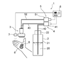
- FIG. 1 is a schematic diagram showing a schematic configuration of an embodiment of a foam discharge device of the present invention.
- FIG. 2 is a longitudinal sectional view of the foam discharge nozzle of the foam discharge apparatus shown in FIG.
- FIG. 3 is an exploded perspective view of the foam discharge nozzle of the foam discharge apparatus shown in FIG. 4A is a diagram showing an example of a foam discharge port formed at the bottom of the foam diffusion space, and is a cross-sectional view taken along the line IV-IV in FIG. 2 with the second porous body omitted.
- FIG. 5B are views showing another example of the foam discharge port formed at the bottom of the foam diffusion space (corresponding to FIG. 4A).
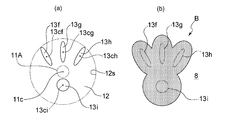
- FIG. 6A is a plan view of the bottom portion showing still another example of the foam discharge port formed at the bottom portion of the foam diffusion space
- FIG. 6B is the shape and arrangement shown in FIG. It is a top view which shows the planar view shape of the foam molded article obtained by this foam discharge port.
- Fig.7 (a) is a top view of this bottom part which shows another example of the foam discharge port formed in the bottom part of foam diffusion space
- FIG.7 (b) is a shape and arrangement
- Fig.8 (a) is a top view of this bottom part which shows another example of the foam discharge port formed in the bottom part of foam diffusion space
- FIG.8 (b) is a shape and arrangement
- Fig.9 (a) is a top view of this bottom part which shows another example of the foam discharge port formed in the bottom part of foam diffusion space
- FIG.9 (b) is a shape and arrangement
- FIG.9 (a) is a top view which shows the planar view shape of the foam molded article obtained by this foam discharge port.
- FIG. 10A is a plan view of the bottom portion showing still another example of the foam discharge port formed at the bottom portion of the foam diffusion space
- FIG. 10B is the shape and arrangement shown in FIG. It is a top view which shows the planar view shape of the foam molded article obtained by this foam discharge port.
- Fig.11 (a) is a top view of this bottom part which shows another example of the foam discharge port formed in the bottom part of foam diffusion space
- FIG.11 (b) is a shape and arrangement
- Patent Document 1 it is difficult to form a desired foam shape even if the formed foam is discharged.
- the technique proposed in Patent Document 2 is difficult to adjust the flow of foam to a plurality of discharge ports and the amount of discharge, and depending on the shape of the modeled object, it is possible to form the modeled foam in a desired shape.
- the technique of patent document 3 is difficult to apply to shapes other than the twisted three-dimensional shape.
- the present invention relates to a foam discharge nozzle and a foam discharge apparatus capable of stably forming a foam shaped article in a desired shape.
- FIG. 1 shows a schematic configuration of a foam discharge device 1 which is an embodiment of the foam discharge device of the present invention.
- the foam discharge device 1 is a foam discharge device including a foam discharge nozzle 3 which is an embodiment of the foam discharge nozzle of the present invention, and foam-like foam generated by mixing the liquid 20 with gas is discharged into the foam. It can be discharged from the nozzle 3.
- the liquid 20 is a liquid soap and the gas is air.
- a foam receiver 8 such as a human hand or a sponge under the foam discharge nozzle 3.
- FIG. 1 shows an example in which foam is ejected onto the palm of a foam receiver 8 that is a human hand, and a foam model B having a snowman-shaped contour is formed on the palm.
- the foam may be discharged onto the back of the hand.
- the foam receiver 8 is a part or object of the body that receives the foam discharged from the foam discharge nozzle 3, and may be a cloth, a cleaning sheet, a desk, etc. in addition to the human hand and sponge described above. .
- the foam discharge device 1 of the present embodiment is an electric foam discharge device, and discharges the liquid storage unit 2, the bubble discharge nozzle 3, and the liquid 20 in the storage unit 2.
- a liquid supply mechanism 4 that supplies the nozzle 3, a gas supply mechanism 5 that takes in ambient air (gas) and supplies it to the bubble discharge nozzle 3, and the liquid supply mechanism 4 and the gas supply when a predetermined signal is input
- a control unit 6 that automatically drives the mechanism 5 for a certain period of time is provided.
- the foam discharge device 1 of the present embodiment includes a non-contact sensor 7 that detects that a foam receiver 8 such as a human hand or a sponge is disposed under the foam discharge nozzle 3. When the detection signal when the bubble receiver 8 is detected is input, the control unit 6 automatically drives the liquid supply mechanism 4 and the gas supply mechanism 5 for a certain period of time.
- the storage unit 2 is composed of a container having a container body 21 and a cap 22 that can close the upper end opening of the container body 21 in an airtight manner.
- the liquid supply mechanism 4 includes a liquid pump 41 including an electric motor, a first connection pipe 42, and a second connection pipe 43, and stores while the liquid pump 41 is operating under the control of the control unit 6.
- the liquid 20 is sucked up from the inside of the unit 2 and the sucked liquid 20 is supplied to the bubble discharge nozzle 3.
- a centrifugal pump such as a spiral pump, a positive displacement pump such as a syringe pump, a gear pump, a diaphragm pump, a piezo pump, or the like is preferably used.
- the gas supply mechanism 5 includes an air pump 51 provided with an electric motor and an air supply pipe 52, and while the air pump 51 is operating under the control of the control unit 6, outside air from an intake hole (not shown) is supplied. Inhalation and inhaled air are supplied to the bubble discharge nozzle 3.
- the air pump 51 for example, a centrifugal pump such as a spiral pump, a positive displacement pump such as a syringe pump, a gear pump, a diaphragm pump, a piezo pump, or the like is preferably used.
- the first connection pipe 42, the second connection pipe 43, and the air supply pipe 52 for example, a tube made of rubber or synthetic resin, a metal pipe, or the like is used.
- the first connection pipe 42, the second connection pipe 43, and the air supply pipe 52 are preferably flexible.
- the control unit 6 includes an arithmetic processing unit, a storage unit, and a power supply unit, and is electrically connected to the electric motor of the liquid pump 41, the electric motor of the air pump 51, and the sensor 7.
- the arithmetic processing unit includes a microprocessor such as a CPU and MPU, the storage unit includes a ROM and a RAM, and stores programs and various data for causing the arithmetic processing unit to perform predetermined processing.
- the control unit 6 receives a signal detected by the sensor 7 when a foam receiver 8 such as a human hand or sponge is placed under the foam discharge nozzle 3, and controls each of the electric motors of the liquid pump 41 and the air pump 51. Control is performed so that driving is started.
- the power supply unit supplies power to the electric motors and control units of the liquid pump 41 and the air pump 51.
- the power supply unit is composed of a dry cell storage box, a secondary battery, or an internal or external AC-DC converter.
- various known sensors known as human sensors such as a pyroelectric sensor and a sensor composed of an infrared light emitting diode and an infrared light receiving diode, can be used.
- the foam discharge nozzle 3 in the foam discharge apparatus 1 includes a gas-liquid mixing unit 32 that mixes liquid and gas, and a first porous body 33 disposed downstream of the gas-liquid mixing unit 32.
- a bubble generating mechanism 31 is provided.
- the gas-liquid mixing unit 32 includes a merging unit 32a, a communication path 32b, and a mixing chamber 32c.
- the bubble discharge nozzle 3 in the bubble discharge apparatus 1 is comprised from each member shown in FIG.
- the foam discharge nozzle 3 includes a former case 34 that includes a cylindrical case body 35 and a cap 35d that is airtightly attached to an upper end opening of the cylindrical case body 35.
- the former case 34 has a through hole 35a penetrating vertically at the bottom center thereof, more specifically at the bottom center of the case main body 35.
- the former case 34 has an upper portion in the periphery surrounding the through hole 35a at the bottom portion of the former case 34.
- a cylindrical support portion 35b protruding toward the bottom and a connecting cylindrical portion 35c protruding downward are formed.
- the foam generation mechanism 31 in the foam discharge device 1 of the present embodiment includes a former member 36 and a cylindrical joint member 37, and the gas-liquid mixing unit 32 is formed by the former member 36 and the joint member 37. Yes.
- the confluence portion 32a of the gas-liquid mixing portion 32 is formed in an annular recess between the guide rod portion 36b of the former member 36 and the protruding portion 36c located around the lower portion thereof, and the communication path 32b is The through hole extending from the annular recess to the mixing chamber 32c is formed.
- the former member 36 includes a cylindrical portion 36 a that is fitted into the upper end portion of the cylindrical support portion 35 b of the former case 34, and the mixing chamber 32 c of the gas-liquid mixing portion 32 is a cylinder of the former member 36.
- the alignment guide rod portion 36b projects upward while being supported from the inner peripheral surface of the upper end portion of the cylindrical portion 36a.
- the joint member 37 includes a large-diameter cylindrical portion 37a, a small-diameter cylindrical portion 37c, and a connecting cylindrical portion 37d.
- the large diameter cylindrical portion 37 a has an inner diameter similar to the outer diameter of the cylindrical support portion 35 b of the former case 34.
- the small-diameter cylindrical portion 37c is continuously provided above the large-diameter cylindrical portion 37a via a stepped portion 37b.
- the connecting cylindrical portion 37d is continuously provided above the small diameter cylindrical portion 37c via a stepped portion.
- the joint member 37 inserts the guide rod portion 36b of the former member 36 into the small-diameter cylindrical portion 37c, and fits the large-diameter cylindrical portion 37a into the upper end portion of the cylindrical support portion 35b, whereby the cylindrical support portion 35b. Attached to.
- the guide rod portion 36 b of the former member 36 is inserted and arranged inside the small-diameter cylindrical portion 37 c of the joint member 37 to facilitate alignment between the former member 36 and the joint member 37.
- the joint member 37 is held by the case main body 35 in a state where the small-diameter cylindrical portion 37c penetrates the cap 22 up and down, and the connecting cylindrical portion 37d continuously provided above the small-diameter cylindrical portion 37c includes: A second connection pipe 43 of the liquid supply mechanism 4 is connected. Specifically, the outer peripheral surface of the second connection pipe 43 is in close contact with the inner peripheral surface of the connecting tubular portion 37d. In addition, a plurality of liquid circulation grooves are formed on the inner peripheral surface of the small-diameter cylindrical portion 37c so as to extend linearly in the vertical direction.
- the liquid supplied by the liquid supply mechanism 4 is transferred to the merging portion 32a through the liquid circulation groove on the inner peripheral surface of the small diameter cylindrical portion 37c, and merges with the gas at the merging portion 32a.
- the cap 35d is formed with a through-hole 35e penetrating vertically and a connecting cylindrical portion 35f extending upward from the periphery thereof.
- the connecting cylindrical portion 35f includes a supply pipe of the gas supply mechanism 5. 52 is connected. Specifically, the inner peripheral surface of the air supply pipe 52 is connected to the outer peripheral surface of the connecting tubular portion 35f.
- a gas flow groove is formed on the inner peripheral surface of the large-diameter cylindrical portion 37a so as to extend linearly in the vertical direction.
- the air supplied by the gas supply mechanism 5 flows in a space between the inner peripheral surface of the former case 34 and the outer peripheral surface of the joint member 37, and enters the gas flow groove from the lower end side of the joint member 37. Enters, flows in the gas flow groove and reaches the junction 32a.
- a plurality of gas flow grooves are formed to extend in the horizontal direction on the inner surface of the top surface portion of the large-diameter cylindrical portion 37a of the joint member 37, and a plurality of gas flow grooves are also formed on the inner surface of the stepped portion 37b in the vertical direction. Has been.
- the former member 36 is formed with a cylindrical projecting portion 36c projecting upward around the lower portion of the guide rod portion 36b.
- the protruding portion 36c is formed at a constant interval from the outer peripheral surface of the guide rod portion 36b, and an annular recess is formed between the guide rod portion 36b and the protruding portion 36c.
- the inside of the annular recess functions as the above-described joining portion 32a.
- a plurality of through holes penetrating up and down at predetermined intervals are formed at the bottom of the recess, and these through holes function as the communication path 32b described above.
- the gas flow groove described above also extends to the inner peripheral surface of the joint member 37 facing the cylindrical protrusion 36c, and the air that has entered the gas flow groove from the lower end side of the joint member 37 flows into the gas flow groove. It reaches the upper end position of the cylindrical projecting portion 36c through the groove, and is jetted from the joining portion 32a.
- the liquid merged with the gas in the merge section 32a is mixed with the gas while flowing through the merge section 32a, the communication path 32b, and the mixing chamber 32c, which is the gas-liquid mixing section 32 in the present apparatus 1, and produces coarse bubbles.
- the first porous body 33 disposed in the lower end opening of the cylindrical portion 36a of the former member 36 that is the outlet of the gas-liquid mixing portion 32 it becomes a foam-like bubble in which minute bubbles are gathered, It is sent out from the lower surface of the first porous body 33 to the foam discharge path 3a.
- the first porous body 33 a synthetic resin or metal mesh sheet, a sintered body of metal particles, a sponge-like molded body of a synthetic resin having a three-dimensional network structure, or the like can be used.
- various known methods such as heat sealing, ultrasonic sealing, adhesive, and fitting into the lower end portion of the large-diameter cylindrical portion 37a can be employed.
- the bubble discharge nozzle 3 in the present apparatus 1 includes a bubble diffusion space 3B below the first porous body 33 as shown in FIG. Further, the lower end opening 32d of the cylindrical portion 36a of the former member 36, which is the outlet of the gas-liquid mixing unit 32 described above, serves as the bubble supply port 11 for supplying bubbles to the bubble diffusion space 3B. More specifically, the lower end opening 32d covered with the first porous body 33 is the bubble supply port 11 in the present embodiment.
- the bubble supply port 11 is located above the bubble diffusion space 3 ⁇ / b> B, and bubbles generated by mixing the liquid 20 with gas are supplied into the bubble diffusion space 3 ⁇ / b> B through the bubble supply port 11.
- the bubble diffusion space 3B is a space for diffusing the bubbles supplied to the bubble diffusion space 3B in a direction intersecting with the bubble protruding direction T, and the bubbles supplied to the bubble diffusion space 3B pass through the bubble diffusion space 3B. After moving downward and diffusing also in the horizontal direction, the liquid is discharged downward from the foam discharge port 13 formed in the bottom 12 of the foam diffusion space 3B.
- the upper side and the upper side are the upper side and the upper side in the vertical direction in the usage state of the device 1
- the lower side and the lower side are the lower side in the vertical direction in the usage state of the device 1 and It is down.
- the bottom 12 of the bubble diffusion space 3B is formed at a portion facing the bubble supply port 11.
- the area of the bottom 12 of the bubble diffusion space 3 ⁇ / b> B is wider than the area of the bubble supply port 11.
- the area of the bottom 12 of the bubble diffusion space 3B is a plan view area of the upper surface facing the bubble diffusion space 3B and includes the area of the bubble discharge port 13.
- the first porous body 33 is provided in the bubble supply port 11, but the area of the bubble supply port 11 is the area of the lower end opening of the cylindrical portion 36 a of the former member 36, The area of the outlet 32d is the same.
- the bubble diffusion space 3 ⁇ / b> B in the apparatus 1 includes a lower space 3 ⁇ / b> C formed inside a horizontal diffusion promoting member 38 coupled below the former case 34, a first porous body 33, and a lower space. It consists of the upper space 3D located between 3C.
- the upper space 3D is a portion located below the first porous body 33 in the hollow portion formed inside the cylindrical body 35g forming the through hole 35a in the bottom portion of the former case 34.
- the cylindrical body 35g in the apparatus 1 is formed of the above-described cylindrical support portion 35b, the through hole 35a, and the connecting cylindrical portion 35c.
- the lower space 3C is a portion located below the connecting cylindrical portion 35c in the hollow portion formed inside the horizontal diffusion promoting member 38.
- the cross-sectional area of the plane perpendicular to the foam discharge direction T is larger than the area of the foam supply port 11 over the entire area in the height direction of the foam discharge nozzle 3. ing.
- the cross-sectional shape of the inner peripheral surface is circular, and the shape of the bottom portion 12 in plan view is also circular.
- the centroid 11c of the supply port projection unit 11A overlaps the center of the bubble diffusion space 3B having a circular cross-sectional shape.
- the horizontal diffusion promoting member 38 has an outer peripheral surface having a larger diameter than the outer peripheral surface of the former case 34, and has a hollow portion penetrating the horizontal diffusion promoting member 38 in the vertical direction. At the upper end portion of the horizontal diffusion promoting member 38, there is a connecting tubular portion 38b protruding so as to surround the hollow portion, and the connecting tubular portion of the former case 34 is provided inside the connecting tubular portion 38b. The portion 35c is connected to the lower portion of the former case 34 by fitting.
- the lower space 3C formed inside the horizontal diffusion promoting member 38 has an inner peripheral surface having a larger inner diameter at the lower end than at the upper end, and a cross-sectional area by a plane orthogonal to the foam discharge direction T expands from the upper side to the lower side. is doing. Further, the discharge port forming member 39 is fitted and fixed to the lower end portion of the hollow portion of the horizontal diffusion promoting member 38.
- the lower space 3C in the present embodiment includes a cross-sectional area enlarged portion 38c in which a cross-sectional area by a plane orthogonal to the foam discharge direction T gradually expands from above to below, and a cross-sectional area by a plane orthogonal to the foam discharge direction T. Has a constant cross-sectional area non-change portion 38d in the vertical direction. In the present embodiment, also in the upper space 3D, the cross-sectional area by a plane orthogonal to the bubble discharge direction T is constant in the vertical direction.
- the cross-sectional shape of the bubble diffusion space 3B, and the shape of the former case 34 and the horizontal diffusion promoting member 38 for forming the bubble diffusion space 3B are not limited to the shape of the present embodiment. It can be arbitrarily designed in consideration of the design and the amount of foam discharged.
- the cross-sectional area by a plane orthogonal to the foam discharge direction T may gradually increase from the upper side to the lower side, and the lower space 3C may not include the cross-sectional area non-changing portion 38d.
- the outer side of the cross-sectional area enlarged portion 38c of the horizontal diffusion promoting member 38 may have a shape that gradually increases in the same manner as the shape of the hollow portion.
- a discharge port forming member 39 is fitted and fixed to the lower end portion of the horizontal diffusion promoting member 38.
- the bubble diffusion space 3B in the present embodiment is a space from the lower surface of the first porous body 33 disposed at the outlet of the gas-liquid mixing unit 32 to the upper surface of the discharge port forming member 39, and is orthogonal to the bubble discharge direction T.
- the cross-sectional area by the plane to be is a part larger than the area of the bubble supply port 11.
- the bubble discharge direction T is a direction parallel to the central axis of the bubble diffusion space 3B.
- the direction parallel to the central axis of the bubble diffusion space 3B is, for example, when the bubble diffusion space 3B has a rotating body shape such as a columnar shape or a conical shape, the bubble discharge direction T is the rotation of the rotating body.
- the direction is parallel to the central axis of the rectangular tube.
- the direction parallel to the central axis of the bubble diffusion space 3B is relative to the upper surface of the bottom 12 of the bubble diffusion space 3B.
- the foam discharge device 1 is preferably used with the foam discharge direction T of the foam discharge nozzle 3 aligned with the vertical direction X.
- the bubble discharge direction from the outlet 32d of the gas-liquid mixing unit 32 to the bubble diffusion space 3B is also the bubble discharge direction T, and preferably coincides with the vertical direction X.
- the direction from the upper side to the lower side which is the traveling direction of the liquid 20 and the foam, is the vertical direction.
- the expression “matches the vertical direction” includes the case where the bubble discharge direction T is parallel to the vertical direction and the bubble discharge direction T is inclined with respect to the vertical direction, but the inclination angle is within 5 °. Is included.
- shaft corresponds with the structural member of the foam discharge nozzle 3 of this embodiment.
- the maximum value of the cross-sectional area of the bottom 12 and the plane orthogonal to the bubble discharge direction T is preferably twice or more, more preferably 10 times the area of the bubble supply port 11, respectively. Or more, more preferably 50 times or more, preferably 1000 times or less, more preferably 200 times or less, still more preferably 100 times or less, and preferably 2 times or more and 1000 times or less, more preferably 10 times or more. It is 200 times or less, More preferably, it is 50 times or more and 100 times or less.
- the maximum value of the cross-sectional area by the plane perpendicular to the area of the bottom portion 12 and the bubble discharge direction T is preferably 0.5 cm 2 or more, more preferably 2.8 cm 2 or more. It is preferably 300 cm 2 or less, more preferably 30 cm 2 or less.
- the maximum value of the cross-sectional area of the bubble diffusion space 3B is the cross-sectional area of the portion where the cross-sectional area of the bubble diffusion space 3B is maximized by a plane orthogonal to the foam discharge direction T.
- This is the cross-sectional area of the cross-sectional area non-changing portion 38d.
- the bubble diffusion space 3 ⁇ / b> B has a portion having a maximum cross-sectional area immediately before the portion adjacent to the bubble discharge port 13 or the second porous body 40.
- the discharge port forming member 39 is a member that forms the foam discharge port 13 having a predetermined shape in the bubble discharge nozzle 3, and the discharge port forming member 39 has, for example, the shape shown in FIG. 4 on the bottom 12 of the bubble diffusion space 3B. And a plurality of foam outlets 13 arranged are formed.
- the bubble discharge port 13 penetrates the discharge port forming member 39 that forms the bottom 12 of the bubble diffusion space 3B in the thickness direction.
- the shape and arrangement of the bubble discharge ports 13 are preferably the same over the entire area in the thickness direction of the discharge port forming member 39.
- the bubble diffusion space 3B preferably has a flat surface directed toward the bubble diffusion space 3B around the bubble discharge port 13 from the viewpoint of diffusing foam-like bubbles along the bottom portion 12.
- the upper surface 12a of the bottom 12 of the bubble diffusion space 3B preferably extends in a direction perpendicular to the bubble discharge direction T, and as in the present embodiment, an annular continuous plane surrounding the bubble discharge port 13 14 is preferable.
- Fig.4 (a) two foams mutually spaced apart as the foam discharge port 13 in the bottom part 12 of the bubble diffusion space 3B.
- Discharge ports 13a and 13b are formed.
- the two bubble discharge ports 13a and 13b are supplied by projecting the aforementioned bubble supply port 11 onto the bottom 12 of the bubble diffusion space 3B in parallel with the central axis of the bubble diffusion space 3B. It does not overlap with the centroid 11c of the mouth projection unit 11A, and each centroid 13c of the two bubble discharge ports 13a and 13b also overlaps with the supply port projection unit 11A as shown in FIG. 4A. Not.
- centroid of the bubble discharge port in the case of having a plurality of bubble discharge ports spaced apart from each other is the centroid of each bubble discharge port.
- the centroid is obtained from the shape of each foam outlet when the bottom of the foam diffusion space is viewed in plan. As shown in FIG. 4, when the shape of the foam outlet is circular, the center of the circle is the centroid.
- the centroid in the case of a non-circular shape can be easily obtained by using commercially available CAD or drawing creation software.
- the foam discharge apparatus 1 of this embodiment as shown to Fig.4 (a), several foam discharge outlets 13a and 13b formed in the bottom part 12 of the bubble diffusion space 3B supply all of them. It does not overlap with the mouth projection unit 11A.
- the supply port projection unit 11A is a portion obtained by projecting the opening shape of the bubble supply port 11 onto the bottom 12 in parallel with the central axis of the bubble diffusion space 3B. In FIG. 4A, the supply port projection unit 11A It is an area.
- the bubble discharge direction T, the direction parallel to the central axis of the bubble diffusion space 3B, and the vertical direction X are parallel, and the diameter and area of the supply port projection unit 11A are the same as the bubble supply port 11.
- the diameter and the opening area of the lower end opening 32d of the cylindrical portion 36a of the former member 36 are the same. Moreover, when the bubble discharge port 13 and the supply port projection part 11A overlap only in the periphery of each other, it is assumed that the bubble discharge port 13 and the supply port projection part 11A do not overlap.
- the foam discharge device 1 of the present embodiment when a foam receiver 8 such as a human hand or a sponge is placed under the foam discharge nozzle 3, the sensor 7 detects it and sends a detection signal to the control unit 6. send. Upon receiving the signal from the sensor 7, the control unit 6 drives the liquid supply mechanism 4 and the gas supply mechanism 5 for a predetermined time. Accordingly, a certain amount of liquid is supplied to the bubble discharge nozzle 3 by the liquid supply mechanism 4, and a certain amount of air is supplied to the bubble discharge nozzle 3 by the gas supply mechanism 5. A certain amount of foam-like foam is discharged from a discharge port onto a foam receiver 8 such as a human hand or a sponge.
- foam generated by mixing the liquid 20 with gas is supplied from the foam supply port 11 into the foam diffusion space 3B, and the foam travels downward in the foam diffusion space 3B.
- the plurality of bubble discharge ports 13a and 13b are arranged so that the respective centroids 13c do not overlap the centroid 11c of the supply port projection unit 11A, some of the bubbles are It strikes a portion other than the bubble discharge port 13 and diffuses in the horizontal direction along the bottom portion 12.
- the foam-like foam supplied into the foam diffusion space 3B is discharged onto the foam receiver 8 such as a palm or sponge at a speed averaged from each part of the plurality of foam discharge ports 13a and 13a.
- the shape and arrangement of the foam outlet 13 it is possible to stably form the foam shaped object B having the desired shape outline on the palm of the human hand, the back of the hand, the surface of the sponge, and the like.
- the foam-shaped bubbles are bubbled at a more averaged speed.
- the moldability of the foamed molded article B that is discharged onto the receiver 8 and has a predetermined plan view shape is further improved.
- the individual foam discharge ports 13a and 13b are also arranged so as not to overlap the supply port projection unit 11A, the foam-like foam supplied into the foam diffusion space 3B is more reliably a plurality of foams. It discharges on the bubble receiving body 8 such as a palm or a sponge at a speed averaged from each part of the discharge ports 13a and 13a. Therefore, the moldability of the foam shaped article B having a predetermined plan view shape is further improved.
- FIG. 4B is a diagram showing a foamed object B having a snowman-like shape in plan view, which is formed on the foam receiver 8 by the foam discharge ports 13 having the shape and arrangement shown in FIG. .
- the foamed object B having a snowman-like shape in plan view has a large area part b1 and a small area part b2 having different sizes when seen in a plan view, and the large area part b1 mainly includes two bubbles.
- the small area portion b2 is mainly formed by bubbles discharged from the first discharge port 13a, which is one of the discharge ports 13a, 13b, and the second discharge port, which is the other of the two bubble discharge ports 13a, 13b. It is formed by bubbles discharged from the outlet 13b.
- the foam when forming the foam shaped article B having the large area part b1 and the small area part b2 having different sizes when viewed in plan, the foam is a viscoelastic body and is close to the supply port projection part 11A. Since a large amount is easily discharged from the bubble discharge port, as shown in FIG. 4A, the first discharge port 13a that mainly discharges the foam that forms the large area portion b1 and the centroid 11c of the supply port projection unit 11A It is also preferable that the distance La is shorter than the distance Lb between the second discharge port 13b that mainly discharges the bubbles that form the small area portion b2 and the centroid 11c of the supply port projection unit 11A.
- the first discharge port 13a and the second discharge port 13b may have an area of the first discharge port 13a larger than that of the second discharge port 13b, but the area of the first discharge port 13a and the second discharge port The area of 13b can be made the same.
- the area of the 1st discharge port 13a and the area of the 2nd discharge port 13b are made the same, about the discharge port of the direction which wants to be made into the large area part of the foam molded article B, it is with the centroid 11c of the supply port projection part 11A. Increase the distance between.
- the distance Lb is made longer than the distance La, or the distance La is made shorter than the distance Lb, thereby discharging bubbles forming the large area portion b1.
- the area of the first discharge port 13a can be made smaller than the area of the second discharge port 13b.
- the first discharge that simply discharges the foam that forms the large area part b1. It is also possible to adopt a method in which the area of the outlet 13a is made larger than the area of the second discharge port 13b that discharges bubbles forming the small area part b2. It is possible to use both the method of changing the area and the method of changing the distance.
- the foam When forming a foam shaped article B having a large area part b1 and a small area part b2 having different sizes when seen in a plan view, the foam is a viscoelastic body and is directed to a direction in which it flows easily and an outlet with less resistance. 10 (a) and 10 (b), the distance between the first discharge port 13a that discharges the bubbles forming the large area portion b1 and the centroid 11c of the supply port projection unit 11A.
- La is shorter than the distance Lb between the first discharge port 13b that discharges the bubbles forming the small area portion b2 and the centroid 11c of the supply port projection unit 11A, the first relative to the area Sb of the second discharge port 13b.
- the ratio (Ga / Gb) of the area Gb of the large area portion b1 to the area Gb of the small area portion b2 is larger than the ratio (Sa / Sb) of the area Sa of the discharge port 13a.
- the area Sa of the first discharge port 13a is equal to the area Sb of the first discharge port 13b as shown in FIG. Is smaller than the distance Lb between the first discharge port 13b and the centroid 11c of the supply port projection unit 11A.
- the ratio of the area Gb of the large area part b1 to the area Gb of the small area part b2 (Ga / Gb) than the ratio of the area Sa of the first outlet 13a to the area Sb of the second outlet 13b (Sa / Sb). ) Increases and the first discharge port 13a having a small area Sa discharges bubbles forming the large area portion b1.
- the first discharge port 13a and the small area portion b2 for discharging the bubbles forming the large area portion b1 are formed.
- the second discharge port 13b for discharging bubbles is preferably formed to satisfy the following formula (1).
- Ga is the area of the large area portion
- Gb is the area of the small area portion
- Sa is the area of the first discharge port 13a
- La is the centroid 13ca of the first discharge port 13a and the supply port projection unit 11A.
- ⁇ is a real number not less than 0.1 and not more than 2.
- ⁇ is a coefficient determined in consideration of the ease of flow of bubbles, and varies depending on the liquid 20 used, the bubble generation mechanism 31 and the like. ⁇ is obtained in advance from the liquid 20 to be used and the foam formed by the foam generating mechanism 31 and the like as follows.
- a second discharge port 13b having an area Sb that is twice the area Sa of the first discharge port 13a and the first discharge port 13a is arranged at the same distance from the centroid 11c of the supply port projection unit 11A of the bubble supply port 11.
- a nozzle 3 is prepared.
- the foam shaped object B is discharged from the first discharge port 13a and the second discharge port 13b, and the area Ga of the large area part b1 and the area Gb of the small area part b2 are measured.
- the measurement result is applied to Equation (1), and ⁇ is calculated.
- FIG. 5A and FIG. 5B show another example of the foam discharge port 13 formed at the bottom 12 of the foam diffusion space 3B.
- a plurality of main discharge portions 113a and 113b are connected to the bottom portion 12 of the bubble diffusion space 3B as a bubble discharge port 13 through slit-like narrow boundary discharge portions 113d.
- a bubble discharge port 13d having the above configuration is formed.
- the centroid 13c of the bubble discharge port 13d does not overlap with the centroid 11c of the supply port projection unit 11A, and the centroid 13c of the bubble discharge port 13d is as shown in FIG. As shown to a), it does not overlap with supply port projection part 11A.
- FIG. 5A the centroid 13c of the bubble discharge port 13d does not overlap with supply port projection part 11A.
- the bubble discharge port 13d does not overlap the supply port projection unit 11A.
- the centroid 13c of the bubble discharge port 13d is the center of gravity of the plate-like body assuming a plate-like body having the same shape and size as the bubble discharge port 13 and a uniform density at the position of the bubble discharge port 13.
- the centroid 13c of the bubble discharge port 13d can also be obtained by the following method. That is, the centroid 13c of the bubble discharge port 13d is not the centroid of each of the bubble discharge ports 113a and 113b, but two arbitrary axes perpendicular to each other are defined on the plane where the bubble discharge port 13d exists.
- the positions of the centroids of the discharge units 113a and 113b and the boundary discharge unit 113d are (Ax, Ay) (Bx, By) (Cx, Cy) (the same applies hereinafter), the bubble discharge units 113a and 113b, and the boundary discharge unit 113d.
- SA is the area of SA, SB, SC (the same applies hereinafter)
- S-all is the total area of the bubble discharge port 13d
- the coordinates of the centroid 13c are (Mx, My). It is a coordinate (Mx, My) that satisfies (Expression).
- SA ⁇ Ax + SB ⁇ Bx + SC ⁇ Cx +... S-all ⁇ Mx (1 set)
- SA x Ay + SB x By + SC x Cy + ... S-all x My (2 formulas)
- the centroid 13c of the bubble discharge port 13d can be easily obtained by using commercially available CAD or drawing creation software.
- FIG. 5B a configuration in which a plurality of main discharge portions 113a and 113b are connected to the bottom portion 12 of the bubble diffusion space 3B as a bubble discharge port 13 via a narrow boundary discharge portion 113e.
- the foam discharge port 13e which has is formed.
- the centroid 13c of the bubble discharge port 13e does not overlap with the centroid 11c of the supply port projection unit 11A, and the centroid 13c of the bubble discharge port 13e is not shown in FIG. As shown to b), it does not overlap with supply port projection part 11A.
- FIG. 5B a configuration in which a plurality of main discharge portions 113a and 113b are connected to the bottom portion 12 of the bubble diffusion space 3B as a bubble discharge port 13 via a narrow boundary discharge portion 113e.
- the foam discharge port 13e which has is formed.
- the centroid 13c of the bubble discharge port 13e does not overlap with the centroid 11c of the supply port projection unit 11A, and the centroid 13c of the bubble discharge port 13e
- the bubble discharge port 13e partially overlaps the supply port projection unit 11A, but the bubble discharge port 13e is also arranged so as not to overlap the supply port projection unit 11A. It is preferable.
- the area where the bubble discharge port 13e and the supply port projection unit 11A overlap is preferably 0 to 30%, more preferably 0 to 10%, of the area of the bubble discharge port 13e.
- the centroid 13c of the bubble discharge port 13e is obtained in the same manner as the centroid 13c of the bubble discharge port 13d described above. However, since the boundary discharge portion 113e has no area, the centroid of the boundary discharge portion 113e is ignored. Ask. Further, the cross-sectional shape of the bubble discharge port 13e is a shape in which the circular main discharge portions 113a and 113b overlap each other, and the main discharge portions 113a and 113b are not completely circular, but are each circular and positioned at the centroid. Determine. The centroid 13c of the bubble discharge port 13e can be easily obtained even by using commercially available CAD or drawing creation software.
- Bubble discharge ports 13d and 13e having the shape and arrangement shown in FIG. 5 (a) or FIG. 5 (b) are formed at the bottom 12 of the bubble diffusion space 3B of the bubble discharge nozzle 3 of the bubble discharge device 1 of the embodiment described above. Even in the case, the foam-like foam supplied in the foam diffusion space 3B is discharged onto the foam receiver 8 such as a palm or a sponge at a speed averaged from each part of the foam discharge ports 13d and 13e. It is possible to stably form a foam shaped article B having a desired contour on the foam receiver 8.
- the width of the boundary discharge portions 113d and 113e is preferably Is 0.1 mm to 5.0 mm, more preferably 0.5 mm to 2.0 mm.
- the width of the slit-like boundary discharge portion 113d which is the length in the direction orthogonal to the direction in which the boundary discharge portion 113d extends, is the width of the boundary discharge portion 113d.
- the foam model shown in FIG. 4 (b) is formed on the foam receiver 8.
- the large-area part b1 having a large size when viewed in plan of the snowman-like foam shaped object B is mainly from the first discharge part 113a which is one of the two main discharge parts 113a and 113b.
- the small area part b2 formed by the discharged bubbles and having a size in plan view smaller than the large area part b1 is mainly discharged from the second discharge part 113b which is the other of the main discharge parts 113a and 113b. It is formed by bubbles.
- the foam when forming the foam shaped article B having the large area part b1 and the small area part b2 having different sizes when seen in a plan view, the foam is a viscoelastic body, and is easy to flow and has little resistance. From the viewpoint of flowing toward the outlet, as shown in FIG. 5A, between the first discharge portion 113a that mainly discharges the foam that forms the large area portion b1 and the centroid 11c of the supply port projection portion 11A. It is preferable that the distance La is shorter than the distance Lb between the second discharge part 113b that discharges bubbles mainly forming the small area part b2 and the centroid 11c of the supply port projection part 11A.
- the area of the first discharge part 113a and the second discharge part 113b may be larger than the area of the second discharge part 113b, but the area of the first discharge part 113a and the second discharge part 113b may be larger.
- the area of 113b may be the same.
- the difference between the distance Lb and the distance La can be increased so that the area of the first ejection part 113a can be made smaller than the area of the second ejection part 113b.
- the first discharge that simply discharges the foam that forms the large area part b1
- the area of the portion 113a is made larger than the area of the second discharge portion 113b that discharges bubbles forming the small area portion b2. It is possible to use both the method of changing the area and the method of changing the distance.
- the ratio of the area of the first discharge part 113a to the area of the second discharge part 113b is increased, and the first discharge that mainly discharges bubbles forming the large area part b1.
- the distance La between the portion 113a and the centroid 11c of the supply port projection portion 11A is determined between the second discharge portion 113b that mainly discharges bubbles forming the small area portion b2 and the centroid 11c of the supply port projection portion 11A. It can also be longer than the distance Lb.
- the large-area portion b1 is formed from the viewpoint of efficiently forming the desired shaped foam B having a plan view by utilizing the properties of the bubbles. It is preferable that the first discharge part 113a that discharges the bubbles to be discharged and the second discharge part 113b that discharges the bubbles that form the small area part b2 are formed so as to satisfy the above-described formula (1). At this time, the boundary discharge portions 113d and 113e have a small discharge area, and thus can be ignored in the above-described equation (1).
- the foam model B has one large area portion and one small area portion.
- this invention is not restricted to this, When there are a plurality of large area parts and small area parts, respectively, and even if it is foam modeling thing B which has a medium area part in addition to a large area part and a small area part Good. In that case, it is difficult to apply the equation (1) to each discharge port or each main discharge portion, but as described above, from the viewpoint of easy flow of bubbles, each discharge port or each main discharge portion. Adjustment is made by a method of varying the area of the material, a method of varying the distance, and a combination thereof.
- FIG. 6 (a) shows another example of a foam discharge port formed at the bottom 12 of the foam diffusion space 3B.
- the foam discharge ports 13f to 13i having the shape and arrangement shown in FIG. 6 (a) at the bottom 12 of the foam diffusion space 3B of the foam discharge nozzle 3 of the foam discharge apparatus 1 of the embodiment described above, the foam discharge apparatus Each time the foam is quantitatively discharged toward the foam receiver 8 by 1, a foam shaped object B having a feather-like plan view shape of the battledore shown in FIG. 6B is formed on the foam receiver 8. be able to. Also in the example shown in FIG.
- the centroids 13cf to 13ci of the plurality of bubble discharge ports 13f to 13i do not overlap the centroid 11c of the supply port projection unit 11A and the supply port projection unit 11A itself, Further, all the foam discharge ports 13f to 13i do not overlap with the supply port projection unit 11A.
- FIG. 7A shows still another example of the foam discharge port formed at the bottom 12 of the foam diffusion space 3B.
- the foam discharge ports 13j, 13k, and 13r having the shape and arrangement shown in FIG. 7A at the bottom 12 of the foam diffusion space 3B of the foam discharge nozzle 3 of the foam discharge device 1 of the above-described embodiment,
- the foam shaped object B having a plan view shape imitating the face of an animal or a human shown in FIG. 8 can be formed.
- FIG. 8 shows still another example of the foam discharge port formed at the bottom 12 of the foam diffusion space 3B.
- the centroids 13cj and 13ck of the non-annular bubble discharge ports 13j and 13k do not overlap the centroid 11c of the supply port projection unit 11A and the supply port projection unit 11A itself.
- the annular bubble discharge port 13r is formed on the center of the bottom of the bubble diffusion space 3B and on the circumference of a circle centering on the centroid 11c of the supply port projection unit 11A.
- the centroid 13cr overlaps the centroid 11c of the supply port projection unit 11A and the supply port projection unit 11A.
- the bubble discharge port 13r itself does not overlap with the supply port projection unit 11A, and is formed in the vicinity of the periphery 12s of the bottom 12 of the bubble diffusion space 3B along the periphery 12s. There is a sufficient distance between the portion 11A.
- the centroid 13cr may coincide with the centroid 11c of the supply port projection unit 11A or may overlap the supply port projection unit 11A itself.
- the bubble discharge nozzle provided with the bubble discharge port of each shape and arrangement shown in 11 (a) is a preferred embodiment of the second invention.
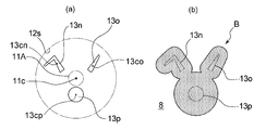
- FIG. 8A shows still another example of the foam discharge port formed at the bottom 12 of the foam diffusion space 3B.
- the foam discharge ports 13n, 13o, and 13p having the shape and arrangement shown in FIG. 8A at the bottom 12 of the foam diffusion space 3B of the foam discharge nozzle 3 of the foam discharge device 1 of the above-described embodiment,
- the foam shaped object B having a planar view shape imitating the face of a rabbit shown in FIG. Can be formed. Also in the example shown in FIG.
- the centroids 13cn, 13co, 13cp of the foam discharge ports 13n, 13o, 13p do not overlap the centroid 11c of the supply port projection unit 11A and the supply port projection unit 11A itself. Moreover, all the bubble discharge ports 13n, 13o, and 13p do not overlap with the supply port projection unit 11A.
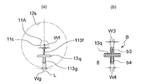
- FIG. 9A shows still another example of the foam discharge port formed at the bottom 12 of the foam diffusion space 3B.
- the bubble discharge port 13q having the shape and arrangement shown in FIG. 9A at the bottom 12 of the bubble diffusion space 3B of the bubble discharge nozzle 3 of the bubble discharge device 1 of the embodiment described above, the bubble discharge device 1
- the foam shaped article B having a cross-shaped plan view shown in FIG. 9B can be formed on the foam receiver 8.
- reference numeral 12s indicates the position of the periphery of the bottom 12 of the bubble diffusion space 3B.
- the foam discharge port 13q shown in FIG. 9A has a proximal portion 113f and a distal portion 113g having different distances from the centroid 11c of the supply port projection portion 11A. Then, the first part b3 of the foam model B is formed by the foam discharged from the proximal part 113f, and the second part b4 of the foam model B is formed by the foam discharged from the distal part 113g. Is done. Then, regarding the width in the direction orthogonal to the straight line L passing through the centroid 11c of the supply port projection part 11A, Wf / W3 which is the ratio of the width Wf of the proximal part 113f to the width W3 of the first part b3 is the second part.
- Wg / W4 is the ratio of the width Wg of the distal portion 113g to the width W4 of b4.
- the shape of the shaped object B is, for example, a triangle, a rectangle, a rhombus, a star, a cross, a card, a heart shape, a clover shape, a spade shape, a rabbit, a cat, an elephant, a bear, and other animals and game characters. And a shape imitating a part of a body such as a face, a shape imitating the contour of a vehicle such as a flower or plant, its fruit, an airplane, an automobile, or a yacht.
- the foam discharge device 1 of the present embodiment includes a second porous body 40 in the foam discharge port 13 of the foam discharge nozzle 3.
- a synthetic resin or metal mesh sheet, a sintered body of metal particles, a synthetic resin sponge-like molded body having a three-dimensional network structure, or the like can be used.
- the second porous body 40 is heat-sealed or superposed on the peripheral portion surrounding the bubble discharge port 13 on the upper end surface of the discharge port forming member 39.
- a method of joining with a sonic seal, an adhesive, or the like, or the second porous body 40 formed to have the same outer peripheral shape as the inner peripheral surface of the foam outlet 13 is fitted inside the foam outlet 13.
- Various methods can be employed such as By disposing the second porous body 40 in the foam discharge port 13, the foam-like foam supplied from the foam supply port 11 diffuses better in the horizontal direction in the foam diffusion space 3B. It is discharged at a speed averaged over the entire area of the bubble discharge port 13. As a result, a foamed article B having a clearer contour shape is formed on the surface of the bubble receiving body 8 such as a human hand.
- the second porous body 40 makes it possible to obtain finer foam-like foam, and it is easier to obtain a foam-shaped article B having a clear outline.
- the second porous body 40 may have the same or different pore diameter as the first porous body 33.
- the area of the second porous body 40 (the area of the upper surface or the lower surface) is preferably equal to or larger than the opening area on the bubble diffusion space 3B side or the external side of the bubble discharge port 13, and on the bubble diffusion space 3B side of the bubble discharge port 13. More preferably, it is larger than the opening area.
- the second porous body 40 is arranged on the bubble diffusion space 3B side of the discharge port forming member 39, the second porous body 40 is more preferably on the entire surface of the discharge port forming member 39 on the bubble diffusion space 3B side. .
- the upper surface 12a of the bottom 12 of the foam diffusion space 3B is formed from the upper surface of the discharge port forming member 39, and the second porous body 40 is on the upper surface of the discharge port forming member 39. It is arranged in a region including a portion overlapping with the bubble discharge port 13 and is preferably arranged over the entire region.
- the area of the second porous body 40 (the area of the upper surface or the lower surface) is preferably larger than the area of the outlet 32d of the gas-liquid mixing unit 32.
- the distance h (refer FIG. 2) from the 1st porous body 33 to the opening part by the side of the cavity of the bubble discharge port 13 from the point which the foamed modeling object B with a clear outline shape becomes easy to form is bubble diffusion.
- the equivalent circular diameter of the bubble diffusion space 3B calculated from the maximum value of the cross-sectional area of the space 3B is preferably 10% or more, more preferably 20% or more, and preferably 100% or less, more preferably 50% or less. is there.
- the distance h (see FIG. 2) is preferably smaller than the equivalent circle diameter of the bubble diffusion space 3B.
- the opening peripheral edge of the external opening protrudes in the bubble discharge direction T.
- the “external opening” is an opening that opens to the opposite side of the bubble diffusion space 3B. In the normal use state of the foam discharge device 1, the peripheral edge of the opening protrudes downward from the foam discharge nozzle 3.
- the horizontal diffusion promoting member 38 and the discharge port forming member 39 are disposed in the concave groove 38 h formed on the inner peripheral surface of the horizontal diffusion promoting member 38.
- the protruding rib 39h formed on the outer peripheral surface of the nozzle By fitting the protruding rib 39h formed on the outer peripheral surface of the nozzle, the boundary portion between them is connected without bonding, and by rotating the discharge port forming member 39 by hand, the bubble discharge port 13 is The position can be changed around the rotation axis extending in the discharge direction T. For example, by making it possible to change the direction of the foam discharge port 13 by such a method, the foam molded in a predetermined shape can be discharged in a desired direction on the foam receiver 8 such as a palm.
- the foam discharge device 1 When the direction of the foam discharge port 13 cannot be changed, the foam discharge device 1 is placed in the back of the washstand with the foam discharge nozzle 3 facing forward, and the foam discharge device 1 is ejected in the left side of the washstand.
- the direction of the foam shaped object B formed on the palm differs between the case where the nozzle 3 is directed to the right side and the case where the foam discharge device 1 is directed to the right side of the washstand and the foam discharge nozzle 3 is directed to the left side.
- the direction of the foam discharge port 13 can be changed and the direction of the foam discharge port 13 is changed according to the installation location of the foam discharge device 1, it depends on the installation location of the foam discharge device 1 on the palm. It is possible to form a foamed object B having the same orientation.
- the four It is also possible to adopt a method for enabling rotation between the mercer 34 and the horizontal diffusion promoting member 38, a method for attaching the foam discharge nozzle 3 to the foam discharge device 1 so that the entire foam discharge nozzle 3 can be rotated, and the like. it can.
- the discharge port forming member 39 is detachable from the horizontal diffusion promoting member 38, and the discharge port forming member 39 is In the removed state, it may be rotated so that the direction of the discharge port 39a is changed to a different direction and can be attached again.
- Making the discharge port forming member 39 detachable also has advantages such as improvement in maintainability and easy change of the shape of the foam model.
- the foam discharge nozzle 3 may be entirely made of synthetic resin, or may be made entirely or partially of a material other than synthetic resin such as metal or ceramic.
- synthetic resin for example, polyolefin such as polyethylene and polypropylene, polystyrene, polyethylene terephthalate (PET), polycarbonate, acrylic, polyamide, polyacetal, vinyl chloride and the like can be used.
- the foam discharged from the foam discharge nozzle 3 has a gas-liquid ratio (the former: latter) of air and liquid.
- the ratio is preferably 5: 1 to 100: 1, more preferably 10: 1 to 50: 1.
- Such bubbles with a gas-liquid ratio can be obtained by adjusting the speed and speed ratio of the gas and liquid sent to the foam discharge nozzle 3 and adjusting the viscosity of the liquid.
- the discharge amount (apparent volume) of one foam is preferably 5 cm 3 or more, more preferably 10 cm 3 or more, and preferably 100 cm 3 or less, more preferably 50 cm 3 or less.
- the amount of foam discharged is a normal volume, normal humidity, and normal pressure (20 ° C, 40RH%, 1 atm). It can be measured by putting the foam.
- the volume of the foam diffusion space 3B is preferably 0.05 to 2 times the foam discharge amount (apparent volume) at one time. 1 to 1 times is more preferable, and 0.2 to 0.8 times is more preferable. Further, the ratio of the volume of the bubble diffusion space 3B to the discharge amount (apparent volume) of one bubble is preferably less than 1 when the use frequency of the bubble discharge device 1 is low.
- the volume of the bubble diffusion space 3B is the volume of the space from the lower surface of the first porous body 33 to the position of the opening 39b on the bubble diffusion space 3B side of the bubble discharge port 13, for example, as shown in FIG.
- the second porous body 40 is arranged on the upper surface 39d of the discharge part forming member where the bubble discharge port 13 is opened, it is assumed that the second porous body 40 is not arranged in the bubble diffusion space 3B.
- the volume In addition, the cross-sectional area of the plane perpendicular to the bubble projecting direction from the lower surface of the first porous body 33 to the upper surface 39d of the discharge portion forming member where the bubble discharge port 13 opens is larger than the area of the outlet of the gas-liquid mixing portion.
- the volume of bubble diffusion space 3B is calculated
- the foam discharge nozzle 3 in the above-described embodiment is composed of a plurality of members, but two or more members are integrally molded, or a single member that is integrally molded is a combination of a plurality of members. It can also be replaced.
- the number of the foam discharge ports 13 formed at the bottom 12 of the foam diffusion space 3B may be single or plural. In a plurality of cases, the bubbles that have passed through the common bubble diffusion space 3 ⁇ / b> B are discharged from the plurality of bubble discharge ports 13.
- centroid 11c of the supply port projection unit 11A may not have the bubble diffusion space 3B of the bubble diffusion space 3B having a circular cross-sectional shape on the inner peripheral surface at the center of the bottom portion 12.
- the cross-sectional shape of the bubble diffusion space 3B may not be circular in plan view.
- the foam discharge device is configured to start supplying gas and liquid to the foam discharge nozzle 3 by detecting a signal from a push button or a contact type sensor instead of a non-contact type sensor.
- the foam discharge device may be used.
- the liquid supply mechanism sends gas into the storage part by an electric air pump or the like, and the liquid surface is pressed by the supplied gas, so that the pressed content liquid is arranged at one end in the content liquid. It may be sent to the foam discharge nozzle 3 through a plastic tube.
- the foam discharge device of the present invention may be a manual device, for example, a device in which air and liquid are sent to the bubble generation mechanism of the bubble discharge nozzle 3 by performing a pressing operation of the pump head. .
- the foam discharge apparatus 1 of embodiment mentioned above accommodates all the components in the housing
- Liquids include detergents such as liquid soap, hand sanitizers that can be made into a foam by adding an activator, hair cosmetics such as hair styling agents, fixing agents, hair restorers, and lotions. Skin cosmetics such as milky lotion and serum, shaving foam, dishwashing detergent and the like may also be used.
- the gas is usually air, but other gases such as nitrogen and helium may be used instead of air.
- the present invention further discloses the following additional notes (foam discharge nozzle, foam discharge device, etc.).
- a foam discharge nozzle of a foam discharge device A bubble diffusion space in which bubbles generated by mixing a liquid with a gas are supplied from a bubble supply port located on the upper side; A single or a plurality of foam outlets formed at the bottom of the foam diffusion space, In the bubble diffusion space, the area of the bottom is wider than the area of the bubble supply port, The bubble discharge nozzle, wherein the centroid of the bubble discharge port does not coincide with the centroid of the supply port projection unit that projects the bubble supply port onto the bottom in parallel with the central axis of the bubble diffusion space.
- ⁇ 2> The bubble discharge nozzle according to ⁇ 1>, wherein the area where the bubble discharge port overlaps the supply port projection unit is 0 to 30% of the area of the bubble discharge port.
- ⁇ 3> The bubble discharge nozzle according to ⁇ 1> or ⁇ 2>, wherein an area of a portion where the bubble discharge port and the supply port projection unit overlap is 0 to 10% of an area of the bubble discharge port.
- ⁇ 4> The bubble discharge nozzle according to any one of ⁇ 1> to ⁇ 3>, wherein a centroid of the bubble discharge port does not overlap with the supply port projection unit.
- ⁇ 5> The bubble discharge nozzle according to ⁇ 4>, wherein the bubble discharge port does not overlap the supply port projection unit.
- a foam discharge nozzle of a foam discharge device A bubble diffusion space in which bubbles generated by mixing a liquid with a gas are supplied from a bubble supply port located on the upper side; Having one or more foam outlets formed at the bottom of the foam diffusion space; In the bubble diffusion space, the area of the bottom is wider than the area of the bubble supply port, The bubble discharge port does not overlap with a supply port projection unit that projects the bubble supply port onto the bottom in parallel with the central axis of the bubble diffusion space, ⁇ 7>
- the bubble discharge nozzle according to any one of ⁇ 1> to ⁇ 6>, wherein the bubble discharge port includes a plurality of bubble discharge ports spaced apart from each other.
- the foam discharge port has a first discharge port that discharges bubbles that form the large area portion and a second discharge port that discharges bubbles that form the small area portion,
- the foam receiver it is possible to form a foam model having a large area part and a small area part having different sizes when viewed in plan
- the bubble discharge port it has a first discharge port for discharging bubbles forming the large area portion, and a second discharge port for discharging bubbles forming the small area portion
- Ga is the area of the large area portion
- Gb is the area of the small area portion
- Sa is the area of the first discharge port
- La is the centroid of the first discharge port and the centroid of the supply port projection unit.
- ⁇ is a real number not less than 0.1 and not more than 2.
- the main discharge part has a first discharge part that mainly discharges bubbles that form the large area part, and a second discharge part that mainly discharges bubbles that form the small area part.
- the foam discharge port has a foam discharge port having a proximal portion and a distal portion that are different in distance from the centroid of the supply port projection unit, and the foam discharged by the foam discharged from the proximal portion
- the first part is formed
- the second part of the foam model is formed by the foam discharged from the distal part,
- the ratio of the width of the proximal part to the width of the first part is greater than the ratio of the width of the distal part to the width of the second part.
- ⁇ 13> The foam discharge nozzle according to any one of ⁇ 1> to ⁇ 12>, wherein the foam discharge port includes a porous body.
- ⁇ 14> The bubble discharge nozzle according to any one of ⁇ 1> to ⁇ 13>, wherein the position of the bubble discharge port is changeable around a central axis of the bubble discharge nozzle.
- the bubble discharge device is an electric or pump type quantitative discharge device that supplies a fixed amount of bubbles to the bubble diffusion space and discharges a fixed amount of bubbles from the bubble discharge nozzle.
- the foam discharge nozzle according to any one of the above.
- the bubble discharge nozzle according to any one of ⁇ 1> to ⁇ 15>, wherein the bubble discharge nozzle includes a bubble generation mechanism.
- the said foam discharge nozzle is a foam discharge nozzle as described in said ⁇ 16> provided with the foam generation mechanism which has the gas-liquid mixing part which mixes a liquid and gas, and the porous body arrange
- the opening area on the bubble diffusion space side of the bubble discharge space is smaller than the maximum value of the cross-sectional area of the bubble diffusion space, and the bubble passing through the bubble diffusion space is discharged to the outside at the bottom of the bubble diffusion space.
- the top surface of the bottom of the bubble diffusion space is formed from the top surface of the discharge port forming member, and the porous body is disposed in a region including a portion overlapping the bubble discharge port on the top surface of the discharge port forming member.
- a foam ejection apparatus comprising the foam ejection nozzle according to any one of ⁇ 1> to ⁇ 20>.
- the foam discharge nozzle and the foam discharge apparatus of the present invention it is possible to stably form a foam shaped article in a desired shape.
Landscapes
- Health & Medical Sciences (AREA)
- Public Health (AREA)
- Nozzles (AREA)
- Containers And Packaging Bodies Having A Special Means To Remove Contents (AREA)
Abstract
本発明の泡吐出ノズル(3)は、泡吐出装置の泡吐出ノズル(3)であって、液体が気体と混合されて生じた泡が上側に位置する泡供給口(11)から供給される泡拡散空間(3B)と、泡拡散空間(3B)の底部(12)に形成された単一又は複数の泡吐出口(13)とを有しており、泡拡散空間(3B)は、底部(12)の面積が泡供給口(11)の面積より広く、泡吐出口(13)の図心が、泡供給口(11)を泡拡散空間(3B)の中心軸と平行に底部(12)に投影した供給口投影部(11A)の図心と一致していない。
Description
本発明は、泡吐出ノズル及びそれを備えた泡吐出装置に関する。
液体石鹸を気体と混合してムース状の泡として吐出させる泡吐出装置が知られている(特許文献1)。
また、吐出させる泡が特定の形状を有するように泡を吐出させる技術も提案されている。例えば、特許文献2には、ノズルヘッドの押圧操作によって内容液をノズルから泡状に吐出させる泡ポンプ付容器のノズルヘッドに、複数の吐出口が特定の配置及び径で形成された泡吐出用アダプタを装着することによって、キャラクタを模した泡の造形物が1回の押圧操作により形成されるようにすることが提案されている。また、特許文献3には、同様の泡吐出用アダプタであって、ツイストした泡の造形物が1回の押圧操作により形成されるようにしたものが提案されている。
また、吐出させる泡が特定の形状を有するように泡を吐出させる技術も提案されている。例えば、特許文献2には、ノズルヘッドの押圧操作によって内容液をノズルから泡状に吐出させる泡ポンプ付容器のノズルヘッドに、複数の吐出口が特定の配置及び径で形成された泡吐出用アダプタを装着することによって、キャラクタを模した泡の造形物が1回の押圧操作により形成されるようにすることが提案されている。また、特許文献3には、同様の泡吐出用アダプタであって、ツイストした泡の造形物が1回の押圧操作により形成されるようにしたものが提案されている。
本発明は、泡吐出装置の泡吐出ノズルであって、液体が気体と混合されて生じた泡が上側に位置する泡供給口から供給される泡拡散空間と、前記泡拡散空間の底部に形成された単一又は複数の泡吐出口とを有している。前記泡拡散空間は、前記底部の面積が前記泡供給口の面積より広い。前記泡吐出口の図心が、前記泡供給口を前記泡拡散空間の中心軸と平行に前記底部に投影した供給口投影部の図心と一致していない。
本発明は、泡吐出装置の泡吐出ノズルであって、液体が気体と混合されて生じた泡が上側に位置する泡供給口から供給される泡拡散空間と、前記泡拡散空間の底部に形成された一つ又は複数の泡吐出口とを有している。前記泡拡散空間は、前記底部の面積が前記泡供給口の面積より広い。前記泡吐出口は、前記泡供給口を前記泡拡散空間の中心軸と平行に前記底部に投影した供給口投影部と重なっていない。
本発明は、前記の泡吐出ノズルを備えた泡吐出装置を提供するものである。
特許文献1の技術は、造形された泡の吐出を行おうとしても、所望の泡形状の造形は困難である。また、特許文献2が提案する技術は、複数の吐出口への泡の流れや吐出量の調整が困難であり、造形物の形状によっては、泡の造形物を所望の形状に形成することは困難である。また、特許文献3の技術は、ツイストした立体形状以外の形状への応用が難しい。
本発明は、泡の造形物を所望の形状に安定して形成することのできる、泡吐出ノズル及び泡吐出装置に関する。
以下、本発明をその好ましい実施形態に基づいて説明する。
図1には、本発明の泡吐出装置の一実施形態である泡吐出装置1の概略構成が示されている。泡吐出装置1は、本発明の泡吐出ノズルの一実施形態である泡吐出ノズル3を備えた泡吐出装置であり、液体20を気体と混合して生じさせたフォーム状の泡を、泡吐出ノズル3から吐出させることができる。本実施形態では、液体20は液体石鹸であり、気体は空気である。
本実施形態の泡吐出装置1によれば、泡吐出ノズル3の下に、ヒトの手やスポンジ等の泡受け体8を配置することにより泡が一定量吐出され、該泡受け体8上に、泡の造形物Bを所望の形状に安定して形成することができる。図1には、ヒトの手である泡受け体8の手の平上に泡を吐出させ、該手の平上に、雪だるま形の輪郭を有する泡の造形物Bを形成する例が示されている。ヒトの手が泡受け体8である場合、その手の甲上に泡を吐出させても良い。
泡受け体8は、泡吐出ノズル3から吐出される泡を受け止める身体の一部や物であり、前述したヒトの手やスポンジの他、雑巾や清掃シート、机の上等であっても良い。
図1には、本発明の泡吐出装置の一実施形態である泡吐出装置1の概略構成が示されている。泡吐出装置1は、本発明の泡吐出ノズルの一実施形態である泡吐出ノズル3を備えた泡吐出装置であり、液体20を気体と混合して生じさせたフォーム状の泡を、泡吐出ノズル3から吐出させることができる。本実施形態では、液体20は液体石鹸であり、気体は空気である。
本実施形態の泡吐出装置1によれば、泡吐出ノズル3の下に、ヒトの手やスポンジ等の泡受け体8を配置することにより泡が一定量吐出され、該泡受け体8上に、泡の造形物Bを所望の形状に安定して形成することができる。図1には、ヒトの手である泡受け体8の手の平上に泡を吐出させ、該手の平上に、雪だるま形の輪郭を有する泡の造形物Bを形成する例が示されている。ヒトの手が泡受け体8である場合、その手の甲上に泡を吐出させても良い。
泡受け体8は、泡吐出ノズル3から吐出される泡を受け止める身体の一部や物であり、前述したヒトの手やスポンジの他、雑巾や清掃シート、机の上等であっても良い。
より具体的に説明すると、本実施形態の泡吐出装置1は、電動式の泡吐出装置であり、液体20の貯留部2と、泡吐出ノズル3と、貯留部2内の液体20を泡吐出ノズル3に供給する液体供給機構4と、周囲の空気(気体)を取り込んで泡吐出ノズル3に供給する気体供給機構5と、所定の信号が入力されたときに、液体供給機構4及び気体供給機構5を自動的に一定時間駆動させる制御部6を備えている。本実施形態の泡吐出装置1は、泡吐出ノズル3の下にヒトの手やスポンジ等の泡受け体8が配されたことを検知する非接触式のセンサー7を備えており、センサー7が泡受け体8を検知したときの検知信号が入力されたときに、制御部6は、自動的に液体供給機構4及び気体供給機構5を一定時間駆動させる。
貯留部2は、容器本体21と容器本体21の上端開口部を気密に閉鎖可能なキャップ22とを有する容器からなる。液体供給機構4は、電動モータを備えた液体ポンプ41、第1の接続管42及び第2の接続管43を有し、制御部6による制御下に液体ポンプ41が作動している間、貯留部2内からの液体20の吸い上げ及び吸い上げた液体20の泡吐出ノズル3への供給が行われる。液体ポンプ41としては、例えば、渦巻ポンプ等の遠心式ポンプや、シリンジポンプ、ギヤポンプ、ダイヤフラムポンプ、ピエゾポンプ等の容積式ポンプ等が好ましく用いられる。気体供給機構5は、電動モータを備えた空気ポンプ51及び給気管52を有し、制御部6による制御下に空気ポンプ51が作動している間、吸入孔(図示せず)からの外気の吸入及び吸入した空気の泡吐出ノズル3への供給が行われる。空気ポンプ51としては、例えば、渦巻ポンプ等の遠心式ポンプや、シリンジポンプ、ギヤポンプ、ダイヤフラムポンプ、ピエゾポンプ等の容積式ポンプ等が好ましく用いられる。
第1の接続管42,第2の接続管43及び給気管52としては、例えば、ゴムや合成樹脂製のチューブ、金属製の配管等が用いられる。第1の接続管42,第2の接続管43及び給気管52は、可撓性を有することが好ましい。
第1の接続管42,第2の接続管43及び給気管52としては、例えば、ゴムや合成樹脂製のチューブ、金属製の配管等が用いられる。第1の接続管42,第2の接続管43及び給気管52は、可撓性を有することが好ましい。
制御部6は、演算処理部、記憶部及び電源部を有しており、液体ポンプ41の電動モータ、空気ポンプ51の電動モータ及びセンサー7と電気的に接続されている。演算処理部はCPU,MPU等のマイクロプロセッサを備えており、記憶部はROMやRAMを備え、演算処理部に所定の処理を行わせるためのプログラムや各種データが格納されている。制御部6は、泡吐出ノズル3の下にヒトの手やスポンジ等の泡受け体8を配した際にセンサー7が検知した信号を受けて、液体ポンプ41及び空気ポンプ51の各電動モータの駆動が開始されるように制御する。電源部は、液体ポンプ41及び空気ポンプ51の電動モータや制御部等に電力を供給する。電源部は、乾電池の収納ボックス、2次電池、又は内蔵若しくは外付けのAC-DC変換機等からなる。センサー7としては、焦電センサーや、赤外発光ダイオードと赤外受光ダイオードとからなるセンサー等、例えば人感センサーとして知られる公知の各種のセンサーを使用することができる。
泡吐出装置1における泡吐出ノズル3は、図2に示すように、液体と気体とを混合させる気液混合部32及び気液混合部32の下流に配置された第1多孔体33を備えた泡発生機構31を備えている。気液混合部32は、合流部32a、連絡路32b及び混合室32cを有している。泡吐出装置1における泡吐出ノズル3は、図3に示す各部材から構成されている。
泡吐出ノズル3は、筒状のケース本体35とその上端開口部に気密に装着されたキャップ35dとを備えたフォーマーケース34を備えている。フォーマーケース34は、その底部中央、より具体的にはケース本体35の底部中央に上下に貫通する貫通孔35aを有し、フォーマーケース34の底部における貫通孔35aを囲む周辺部に、上方に向かって突出する筒状支持部35b及び下方に向かって突出する接続用筒状部35cが形成されている。
泡吐出ノズル3は、筒状のケース本体35とその上端開口部に気密に装着されたキャップ35dとを備えたフォーマーケース34を備えている。フォーマーケース34は、その底部中央、より具体的にはケース本体35の底部中央に上下に貫通する貫通孔35aを有し、フォーマーケース34の底部における貫通孔35aを囲む周辺部に、上方に向かって突出する筒状支持部35b及び下方に向かって突出する接続用筒状部35cが形成されている。
本実施形態の泡吐出装置1における泡発生機構31は、フォーマー部材36と筒状のジョイント部材37とを備えており、気液混合部32は、フォーマー部材36とジョイント部材37とで形成されている。気液混合部32の前記合流部32aは、フォーマー部材36のガイドロッド部36bとその下部の周囲に位置する突出部36cとの間の環状の凹部内に形成されており、前記連絡路32bは、該環状の凹部から混合室32cまでの貫通孔から形成されている。
また、フォーマー部材36は、フォーマーケース34の筒状支持部35bの上端部分に嵌め込まれる円筒形状部分36aを備えており、気液混合部32の前記混合室32cは、このフォーマー部材36の円筒形状部分36aの内部に形成されている。即ち、この円筒形状部分36aの内側が、内容液と空気とを混合させる混合室32cとなっている。なお、フォーマー部材36においては、円筒形状部分36aの上端部の内周面から支持された状態で、位置合わせ用のガイドロッド部36bが上方に向かって突出している。
また、フォーマー部材36は、フォーマーケース34の筒状支持部35bの上端部分に嵌め込まれる円筒形状部分36aを備えており、気液混合部32の前記混合室32cは、このフォーマー部材36の円筒形状部分36aの内部に形成されている。即ち、この円筒形状部分36aの内側が、内容液と空気とを混合させる混合室32cとなっている。なお、フォーマー部材36においては、円筒形状部分36aの上端部の内周面から支持された状態で、位置合わせ用のガイドロッド部36bが上方に向かって突出している。
ジョイント部材37は、大径筒状部37aと小径筒状部37cと接続用筒状部37dとを備えている。大径筒状部37aは、フォーマーケース34の筒状支持部35bの外径と同様の内径を有している。小径筒状部37cは、段差部37bを介して大径筒状部37aの上方に連設されている。接続用筒状部37dは、段差部を介して小径筒状部37cの上方に連設されている。ジョイント部材37は、小径筒状部37cにフォーマー部材36のガイドロッド部36bを挿入しつつ、大径筒状部37aを筒状支持部35bの上端部分に嵌め込むことによって、筒状支持部35bに取り付けられる。フォーマー部材36のガイドロッド部36bは、ジョイント部材37の小径筒状部37cの内側に挿入配置されて、フォーマー部材36とジョイント部材37との位置合わせを容易にする。
またジョイント部材37は、小径筒状部37cがキャップ22を上下に貫通した状態にケース本体35に保持されており、小径筒状部37cの上方に連設する接続用筒状部37dには、液体供給機構4の第2の接続管43が接続されている。詳細には、接続用筒状部37dの内周面に、第2の接続管43の外周面が密着されている。また小径筒状部37cの内周面には、縦方向に線状に延設して複数の液体流通溝が形成されている。液体供給機構4によって供給された液体は、小径筒状部37cの内周面の液体流通溝を介して、合流部32aに移送され、該合流部32aにおいて気体と合流する。
またキャップ35dには、上下に貫通する貫通孔35e及びその周囲から上方に延在する接続用筒状部35fが形成されており、接続用筒状部35fには、気体供給機構5の給気管52が接続されている。詳細には、接続用筒状部35fの外周面に、給気管52の内周面が接続されている。また大径筒状部37aの内周面には、縦方向に線状に延設して気体流通溝が形成されている。また、気体供給機構5によって供給された空気は、フォーマーケース34の内周面とジョイント部材37の外周面との間の空間を流れ、ジョイント部材37の下端側から、この気体流通溝内に入り、気体流通溝内を流れて合流部32aに到達する。なお、気体流通溝は、ジョイント部材37の大径筒状部37aの天面部の内面にも水平方向に延びて複数本形成され、段差部37bの内面にも、上下方向に延びて複数本形成されている。
またキャップ35dには、上下に貫通する貫通孔35e及びその周囲から上方に延在する接続用筒状部35fが形成されており、接続用筒状部35fには、気体供給機構5の給気管52が接続されている。詳細には、接続用筒状部35fの外周面に、給気管52の内周面が接続されている。また大径筒状部37aの内周面には、縦方向に線状に延設して気体流通溝が形成されている。また、気体供給機構5によって供給された空気は、フォーマーケース34の内周面とジョイント部材37の外周面との間の空間を流れ、ジョイント部材37の下端側から、この気体流通溝内に入り、気体流通溝内を流れて合流部32aに到達する。なお、気体流通溝は、ジョイント部材37の大径筒状部37aの天面部の内面にも水平方向に延びて複数本形成され、段差部37bの内面にも、上下方向に延びて複数本形成されている。
フォーマー部材36は、ガイドロッド部36bの下部の周囲に、上方に向かって突出する筒状の突出部36cが形成されている。突出部36cは、ガイドロッド部36bの外周面との間に一定の間隔を隔てて形成されており、ガイドロッド部36bと突出部36cとの間に、環状の凹部が形成されている。この環状の凹部内は、前述した合流部32aとして機能する。また、この凹部の底部には、所定の間隔で上下に貫通する複数の貫通孔が形成されており、これらの貫通孔が前述した連絡路32bとして機能する。前述した気体流通溝は、筒状の突出部36cと対向するジョイント部材37の内周面にも延在しており、ジョイント部材37の下端側から気体流通溝内に入った空気は、気体流通溝を通って筒状の突出部36cの上端位置まで達し、そこから前述した合流部32aに噴射される。
合流部32aにおいて気体と合流した液体は、本装置1における気液混合部32である、合流部32a、連絡路32b及び混合室32cを流れる間に気体と混合されて粗い泡を生じ、更に、その気液混合部32の出口であるフォーマー部材36の円筒形状部分36aの下端開口部に配置された第1多孔体33を通過することによって微小な泡が集合したフォーム状の泡となって、第1多孔体33の下面から泡の吐出路3aへと送り出される。第1多孔体33としては、合成樹脂製若しくは金属製のメッシュシート、金属粒子の焼結体、3次元的な網目構造を有する合成樹脂のスポンジ状成形体等を用いることができる。第1多孔体33の固定方法としては、ヒートシール、超音波シール、接着剤、大径筒状部37aの下端部への嵌め込み等の各種公知の方法を採用できる。
本装置1における泡吐出ノズル3は、図2に示すように、第1多孔体33の下方に、泡拡散空間3Bを備えている。また、前述した気液混合部32の出口であるフォーマー部材36の円筒形状部分36aの下端開口部32dが、泡拡散空間3Bに泡を供給する泡供給口11となっている。より詳細には、第1多孔体33で覆われている下端開口部32dが、本実施形態における泡供給口11となっている。泡供給口11は、泡拡散空間3Bの上側に位置しており、液体20が気体と混合されて生じた泡が、泡供給口11を通って泡拡散空間3B内に供給される。泡拡散空間3Bは、泡拡散空間3Bに供給された泡を、泡の突出方向Tと交差する方向に拡散させる空間であり、泡拡散空間3Bに供給された泡は、泡拡散空間3B内を下方に向かって移動するとともに水平方向にも拡散した後、泡拡散空間3Bの底部12に形成された泡吐出口13から下方に向かって吐出される。本実施形態の装置1やその構成要素に関し、上側や上方は、装置1の使用状態における鉛直方向の上側や上方であり、下側や下方は、装置1の使用状態における鉛直方向の下側や下方である。泡拡散空間3Bの底部12は、泡供給口11と対向する部位に形成されている。泡拡散空間3Bの底部12は、その面積が、泡供給口11の面積よりも広い。泡拡散空間3Bの底部12の面積は、泡拡散空間3Bに臨む上面の平面視面積であり、泡吐出口13の面積も含める。また泡供給口11には第1多孔体33が設けられているが、泡供給口11の面積は、フォーマー部材36の円筒形状部分36aの下端開口部の面積であり、気液混合部32の出口32dの面積とも同じである。
本装置1における泡拡散空間3Bは、図2に示すように、フォーマーケース34の下方に結合した水平拡散促進部材38の内部に形成された下部空間3Cと、第1多孔体33と下部空間3Cとの間に位置する上部空間3Dとからなる。上部空間3Dは、フォーマーケース34の底部における貫通孔35aを形成する筒状体35gの内部に形成される中空部における、第1多孔体33より下方に位置する部分である。本装置1における筒状体35gは、前述した筒状支持部35b、貫通孔35a及び接続用筒状部35cから形成されている。他方、下部空間3Cは、水平拡散促進部材38の内部に形成された中空部のうち、接続用筒状部35cより下方に位置している部分である。下部空間3C及び上部空間3Dは、何れも、泡の吐出方向Tと直交する平面による断面積が、泡吐出ノズル3の高さ方向の全域に亘って、泡供給口11の面積よりも大きくなっている。本実施形態の装置1における泡拡散空間3Bは、内周面の横断面形状が円形であり、底部12の平面視形状も円形である。本実施形態の装置1は、供給口投影部11Aの図心11cが、横断面形状が円形の泡拡散空間3Bの中心と重なっている。
水平拡散促進部材38は、フォーマーケース34の外周面より大径の外周面を有し、水平拡散促進部材38を上下方向に貫通する中空部を有している。水平拡散促進部材38の上端部には、中空部を囲むように突設された接続用筒状部38bを有し、その接続用筒状部38bの内側にフォーマーケース34の接続用筒状部35cが嵌合することによって、フォーマーケース34の下方に連結されている。水平拡散促進部材38の内部に形成された下部空間3Cは、上端より下端の内径が大きい内周面を有し、泡の吐出方向Tと直交する平面による断面積が上方から下方に向かって拡大している。また、水平拡散促進部材38の中空部の下端部に、吐出口形成部材39が嵌め込まれて固定されている。本実施形態における下部空間3Cは、泡の吐出方向Tと直交する平面による断面積が上方から下方に向かって漸次拡大する断面積拡大部38cと、泡の吐出方向Tと直交する平面による断面積が上下方向に亘って一定の断面積非変化部38dとを有している。本実施形態においては、上部空間3Dも、泡の吐出方向Tと直交する平面による断面積が上下方向に亘って一定である。
なお、泡拡散空間3Bの断面形状、また泡拡散空間3Bを形成するためのフォーマーケース34及び水平拡散促進部材38の形状は、本実施形態の形状には制限されず、泡吐出装置1のデザイン、泡の吐出量等を考慮して、任意に設計できる。例えば、上部空間3Dは、泡の吐出方向Tと直交する平面による断面積が上方から下方に向かって漸次拡大してもよく、下部空間3Cは、断面積非変化部38dを具備しなくてもよい。また、水平拡散促進部材38の断面積拡大部38cの外側は、中空部の形状と同様に漸次拡大する形状としてもよい。
水平拡散促進部材38の下端部には、吐出口形成部材39が嵌め込まれて固定されている。
本実施形態における泡拡散空間3Bは、気液混合部32の出口に配置された第1多孔体33の下面から吐出口形成部材39の上面までの空間であって、泡の吐出方向Tと直交する平面による断面積が、泡供給口11の面積より大きい部分である。泡の吐出方向Tは、泡拡散空間3Bの中心軸と平行な方向である。
泡拡散空間3Bの中心軸と平行な方向とは、例えば、泡拡散空間3Bが、円柱状、円錐状等の回転体状の形状を有する場合、泡の吐出方向Tは、当該回転体の回転軸と平行な方向であり、泡拡散空間3Bが、角柱状の場合はその角筒の中心軸と平行な方向である。泡拡散空間3Bの中心軸の延在方向が一義的に定まらない場合、泡拡散空間3Bの中心軸と平行な方向(泡の吐出方向T)は、泡拡散空間3Bの底部12の上面に対して垂直な方向である。泡吐出装置1は、泡吐出ノズル3の泡の吐出方向Tを、鉛直方向Xと一致させて使用することが好ましい。図2には、泡拡散空間3Bの中心軸に含む平面による縦断面が示されている。
本実施形態においては、気液混合部32の出口32dから泡拡散空間3Bへの泡の吐出方向も、前記泡の吐出方向Tであり、好ましくは鉛直方向Xと一致している。また、本実施形態の泡吐出ノズル3は、液体20及び泡の進行方向である上方から下方に向かう方向は、鉛直方向である。「鉛直方向と一致」という表現には、泡の吐出方向Tが鉛直方向と平行である場合と、泡の吐出方向Tが鉛直方向に対して傾斜しているが、その傾斜角度が5°以内である場合とが含まれる。
なお、図3に示すように、本実施形態の泡吐出ノズル3の構成部材は、中心軸が一致している。
本実施形態における泡拡散空間3Bは、気液混合部32の出口に配置された第1多孔体33の下面から吐出口形成部材39の上面までの空間であって、泡の吐出方向Tと直交する平面による断面積が、泡供給口11の面積より大きい部分である。泡の吐出方向Tは、泡拡散空間3Bの中心軸と平行な方向である。
泡拡散空間3Bの中心軸と平行な方向とは、例えば、泡拡散空間3Bが、円柱状、円錐状等の回転体状の形状を有する場合、泡の吐出方向Tは、当該回転体の回転軸と平行な方向であり、泡拡散空間3Bが、角柱状の場合はその角筒の中心軸と平行な方向である。泡拡散空間3Bの中心軸の延在方向が一義的に定まらない場合、泡拡散空間3Bの中心軸と平行な方向(泡の吐出方向T)は、泡拡散空間3Bの底部12の上面に対して垂直な方向である。泡吐出装置1は、泡吐出ノズル3の泡の吐出方向Tを、鉛直方向Xと一致させて使用することが好ましい。図2には、泡拡散空間3Bの中心軸に含む平面による縦断面が示されている。
本実施形態においては、気液混合部32の出口32dから泡拡散空間3Bへの泡の吐出方向も、前記泡の吐出方向Tであり、好ましくは鉛直方向Xと一致している。また、本実施形態の泡吐出ノズル3は、液体20及び泡の進行方向である上方から下方に向かう方向は、鉛直方向である。「鉛直方向と一致」という表現には、泡の吐出方向Tが鉛直方向と平行である場合と、泡の吐出方向Tが鉛直方向に対して傾斜しているが、その傾斜角度が5°以内である場合とが含まれる。
なお、図3に示すように、本実施形態の泡吐出ノズル3の構成部材は、中心軸が一致している。
泡拡散空間3Bは、底部12の面積及び泡の吐出方向Tと直交する平面による断面積の最大値が、それぞれ、泡供給口11の面積の好ましくは2倍以上であり、より好ましくは10倍以上、更に好ましくは50倍以上であり、また好ましくは1000倍以下、より好ましくは200倍以下、更に好ましくは100倍以下であり、また好ましくは2倍以上1000倍以下、より好ましくは10倍以上200倍以下、更に好ましくは50倍以上100倍以下である。
また、泡拡散空間3Bは、底部12の面積及び泡の吐出方向Tと直交する平面による断面積の最大値が、それぞれ、好ましくは0.5cm2以上であり、より好ましくは2.8cm2以上であり、また好ましくは300cm2以下、より好ましくは30cm2以下である。
また、泡拡散空間3Bは、底部12の面積及び泡の吐出方向Tと直交する平面による断面積の最大値が、それぞれ、好ましくは0.5cm2以上であり、より好ましくは2.8cm2以上であり、また好ましくは300cm2以下、より好ましくは30cm2以下である。
泡拡散空間3Bの断面積の最大値は、泡の吐出方向Tと直交する平面による泡拡散空間3Bの断面積が最大となる部位の断面積であり、本実施形態の泡吐出ノズル3においては、断面積非変化部38dの断面積である。泡拡散空間3Bは、断面積が最大値となる部位を、泡吐出口13に隣接する部位又は第2多孔体40の上方直前に有することが好ましい。
吐出口形成部材39は、泡吐出ノズル3に、所定形状の泡吐出口13を形成する部材であり、吐出口形成部材39によって、泡拡散空間3Bの底部12に、例えば、図4に示す形状及び配置の複数の泡吐出口13が形成される。
泡吐出口13は、泡拡散空間3Bの底部12を形成する吐出口形成部材39を厚み方向に貫通している。泡吐出口13の形状及び配置は、吐出口形成部材39の厚み方向の全域に亘って同じであることが好ましい。泡吐出口13の形状及び配置が変化する場合、底部12の泡拡散空間3B側の面12aにおける泡吐出口13の形状及び配置を、その泡吐出口13の形状及び配置とする。泡拡散空間3Bは、フォーム状の泡を、底部12に沿って拡散させる観点から、泡吐出口13の周囲に、泡拡散空間3B側に向けられた平坦面を有することが好ましい。泡拡散空間3Bの底部12の上面12aは、泡の吐出方向Tと直交する方向に延在していることが好ましく、また、本実施形態におけるように、泡吐出口13を囲む環状の連続平面14を有することが好ましい。
泡吐出口13は、泡拡散空間3Bの底部12を形成する吐出口形成部材39を厚み方向に貫通している。泡吐出口13の形状及び配置は、吐出口形成部材39の厚み方向の全域に亘って同じであることが好ましい。泡吐出口13の形状及び配置が変化する場合、底部12の泡拡散空間3B側の面12aにおける泡吐出口13の形状及び配置を、その泡吐出口13の形状及び配置とする。泡拡散空間3Bは、フォーム状の泡を、底部12に沿って拡散させる観点から、泡吐出口13の周囲に、泡拡散空間3B側に向けられた平坦面を有することが好ましい。泡拡散空間3Bの底部12の上面12aは、泡の吐出方向Tと直交する方向に延在していることが好ましく、また、本実施形態におけるように、泡吐出口13を囲む環状の連続平面14を有することが好ましい。
本実施形態の泡吐出装置1に用いた泡吐出ノズル3においては、図4(a)に示すように、泡拡散空間3Bの底部12に、泡吐出口13として、相互に離間した2つの泡吐出口13a,13bが形成されている。そして、その2つの泡吐出口13a,13bは、それぞれの図心13cが、前述した泡供給口11を、泡拡散空間3Bの中心軸と平行に該泡拡散空間3Bの底部12に投影した供給口投影部11Aの図心11cと重なっておらず、更に、その2つの泡吐出口13a,13bの各図心13cは、図4(a)に示すように、その供給口投影部11Aとも重なっていない。
ここで、相互に離間した複数の泡吐出口を有する場合の泡吐出口の図心は、個々の泡吐出口についての図心である。図心は、泡拡散空間の底部を平面視したときの各泡吐出口の形状から求める。図4に示すように、泡吐出口の形状が円形の場合はその円の中心が図心である。非円形の場合の図心は、市販のCADや図面作成ソフトを用いても容易に求めることができる。
ここで、相互に離間した複数の泡吐出口を有する場合の泡吐出口の図心は、個々の泡吐出口についての図心である。図心は、泡拡散空間の底部を平面視したときの各泡吐出口の形状から求める。図4に示すように、泡吐出口の形状が円形の場合はその円の中心が図心である。非円形の場合の図心は、市販のCADや図面作成ソフトを用いても容易に求めることができる。
また、本実施形態の泡吐出装置1においては、図4(a)に示すように、泡拡散空間3Bの底部12に形成された複数の泡吐出口13a,13bが、そのいずれについても、供給口投影部11Aと重なっていない。
供給口投影部11Aは、泡供給口11の開口形状を、泡拡散空間3Bの中心軸と平行に底部12上に投影した部分であり、図4(a)中、一点鎖線で示す円内の領域である。本実施形態においては、前述した泡の吐出方向Tと泡拡散空間3Bの中心軸と平行な方向と鉛直方向Xとが平行であり、供給口投影部11Aの直径及び面積は、泡供給口11である、フォーマー部材36の円筒形状部分36aの下端開口部32dの直径及び開口面積と同一である。また、泡吐出口13と供給口投影部11Aとが互いの周縁のみにおいて重なっている場合は、泡吐出口13と供給口投影部11Aとが重なっていないものとする。
供給口投影部11Aは、泡供給口11の開口形状を、泡拡散空間3Bの中心軸と平行に底部12上に投影した部分であり、図4(a)中、一点鎖線で示す円内の領域である。本実施形態においては、前述した泡の吐出方向Tと泡拡散空間3Bの中心軸と平行な方向と鉛直方向Xとが平行であり、供給口投影部11Aの直径及び面積は、泡供給口11である、フォーマー部材36の円筒形状部分36aの下端開口部32dの直径及び開口面積と同一である。また、泡吐出口13と供給口投影部11Aとが互いの周縁のみにおいて重なっている場合は、泡吐出口13と供給口投影部11Aとが重なっていないものとする。
本実施形態の泡吐出装置1によれば、泡吐出ノズル3の下にヒトの手やスポンジ等の泡受け体8を配すると、センサー7がそれを検知して、制御部6に検知信号を送る。センサー7からの信号を受けた制御部6は、液体供給機構4及び気体供給機構5を一定時間駆動させる。それにより、液体供給機構4によって泡吐出ノズル3に一定量の液体が供給されるとともに、気体供給機構5によって泡吐出ノズル3に一定量の空気が供給され、それによって、泡吐出ノズル3の泡吐出口から一定量のフォーム状の泡が、ヒトの手やスポンジ等の泡受け体8上に吐出される。
本実施形態の泡吐出装置1によれば、液体20が気体と混合されて生じた泡が、泡供給口11から泡拡散空間3B内に供給され、その泡は、泡拡散空間3B内を下方に向かって移動するが、複数の泡吐出口13a,13bが、それぞれの図心13cが供給口投影部11Aの図心11cと重ならないように配されているため、その泡の一部が、泡吐出口13以外の部分に突き当たり、底部12に沿って水平方向に拡散する。そして、泡拡散空間3B内に供給されたフォーム状の泡は、複数の泡吐出口13a,13aの各部位から平均化された速度で、手の平やスポンジ等の泡受け体8上に吐出される。
そのため、泡吐出口13の形状及び配置を工夫することで、所望の形状の輪郭を有する泡の造形物Bを、安定して、ヒトの手の平や手の甲、スポンジの表面等に形成させることができ、例えば、石鹸や薬液を手の平や手の甲に付けて行う手や顔の洗浄や、石鹸や薬液をスポンジの表面に付けて行う食器、風呂、台所等の洗浄に、楽しさや新鮮さを付与することができる。
そのため、泡吐出口13の形状及び配置を工夫することで、所望の形状の輪郭を有する泡の造形物Bを、安定して、ヒトの手の平や手の甲、スポンジの表面等に形成させることができ、例えば、石鹸や薬液を手の平や手の甲に付けて行う手や顔の洗浄や、石鹸や薬液をスポンジの表面に付けて行う食器、風呂、台所等の洗浄に、楽しさや新鮮さを付与することができる。
また、本実施形態においては、複数の泡吐出口13a,13bは、それぞれの図心13cが供給口投影部11A自体とも重なっていないため、フォーム状の泡が、一層平均化された速度で泡受け体8上に吐出され、所定の平面視形状を有する泡の造形物Bの成形性が一層向上する。
更に個々の泡吐出口13a,13bについても、供給口投影部11Aと重ならないように配されているため、泡拡散空間3B内に供給されたフォーム状の泡が、一層確実に、複数の泡吐出口13a,13aの各部位から平均化された速度で、手の平やスポンジ等の泡受け体8上に吐出される。そのため、所定の平面視形状を有する泡の造形物Bの成形性が一層向上する。
更に個々の泡吐出口13a,13bについても、供給口投影部11Aと重ならないように配されているため、泡拡散空間3B内に供給されたフォーム状の泡が、一層確実に、複数の泡吐出口13a,13aの各部位から平均化された速度で、手の平やスポンジ等の泡受け体8上に吐出される。そのため、所定の平面視形状を有する泡の造形物Bの成形性が一層向上する。
図4(b)は、図4(a)に示す形状及び配置の泡吐出口13により泡受け体8上に形成される、平面視形状が雪だるま状の泡の造形物Bを示す図である。
平面視形状が雪だるま状の泡の造形物Bは、平面視したときの大きさが異なる大面積部b1と小面積部b2とを有しており、大面積部b1は、主として、2つの泡吐出口13a,13bのうちの一方である第1吐出口13aから吐出された泡によって形成され、小面積部b2は、主として、2つの泡吐出口13a,13bのうちの他方である第2吐出口13bから吐出された泡によって形成されている。
平面視形状が雪だるま状の泡の造形物Bは、平面視したときの大きさが異なる大面積部b1と小面積部b2とを有しており、大面積部b1は、主として、2つの泡吐出口13a,13bのうちの一方である第1吐出口13aから吐出された泡によって形成され、小面積部b2は、主として、2つの泡吐出口13a,13bのうちの他方である第2吐出口13bから吐出された泡によって形成されている。
このように、平面視したときの大きさが異なる大面積部b1と小面積部b2とを有する泡の造形物Bを形成する場合、泡は粘弾性体であり、供給口投影部11Aに近い泡吐出口から多く排出されやすいため、図4(a)に示すように、主に大面積部b1を形成する泡を吐出する第1吐出口13aと供給口投影部11Aの図心11cとの間の距離Laを、主に小面積部b2を形成する泡を吐出する第2吐出口13bと供給口投影部11Aの図心11cとの間の距離Lbよりも短くすることも好ましい。
その場合、第1吐出口13aと第2吐出口13bは、第1吐出口13aの面積が第2吐出口13bの面積より大きくても良いが、第1吐出口13aの面積と第2吐出口13bの面積とを同じとすることもできる。第1吐出口13aの面積と第2吐出口13bの面積とを同じとする場合、泡の造形物Bの大面積部としたい方の吐出口について、供給口投影部11Aの図心11cとの間の距離を大きくする。
また、距離Lbと距離Laの差を大きくして、詳細には距離Lbを距離Laより一層長く、または距離Laを距離Lbより一層短くすることで、大面積部b1を形成する泡を吐出する第1吐出口13aの面積を第2吐出口13bの面積より小さくすることもできる。
なお、平面視したときの大きさが異なる大面積部b1と小面積部b2とを有する泡の造形物Bを形成する方法として、単に、大面積部b1を形成する泡を吐出する第1吐出口13aの面積を、小面積部b2を形成する泡を吐出する第2吐出口13bの面積より大きくする方法を採用することもできる。面積を異ならせる方法と距離を異ならせる方法との併
用も可能である。
その場合、第1吐出口13aと第2吐出口13bは、第1吐出口13aの面積が第2吐出口13bの面積より大きくても良いが、第1吐出口13aの面積と第2吐出口13bの面積とを同じとすることもできる。第1吐出口13aの面積と第2吐出口13bの面積とを同じとする場合、泡の造形物Bの大面積部としたい方の吐出口について、供給口投影部11Aの図心11cとの間の距離を大きくする。
また、距離Lbと距離Laの差を大きくして、詳細には距離Lbを距離Laより一層長く、または距離Laを距離Lbより一層短くすることで、大面積部b1を形成する泡を吐出する第1吐出口13aの面積を第2吐出口13bの面積より小さくすることもできる。
なお、平面視したときの大きさが異なる大面積部b1と小面積部b2とを有する泡の造形物Bを形成する方法として、単に、大面積部b1を形成する泡を吐出する第1吐出口13aの面積を、小面積部b2を形成する泡を吐出する第2吐出口13bの面積より大きくする方法を採用することもできる。面積を異ならせる方法と距離を異ならせる方法との併
用も可能である。
平面視したときの大きさが異なる大面積部b1と小面積部b2とを有する泡の造形物Bを形成する場合、泡は粘弾性体であり、流れやすい方向、抵抗の少ない出口に向かって流れるため、図10(a)及び図10(b)に示すように、大面積部b1を形成する泡を吐出する第1吐出口13aと供給口投影部11Aの図心11cとの間の距離Laが、小面積部b2を形成する泡を吐出する第1吐出口13bと供給口投影部11Aの図心11cとの間の距離Lbより短いと、第2吐出口13bの面積Sbに対する第1吐出口13aの面積Saの比(Sa/Sb)より、小面積部b2の面積Gbに対する大面積部b1の面積Gbの比(Ga/Gb)の方が大きくなる。
また同様に泡は粘弾性体であり、流れやすい方向、抵抗の少ない出口に向かって流れるため、図11に示すように、第1吐出口13aの面積Saが、第1吐出口13bの面積Sbが小さくても、第1吐出口13aと供給口投影部11Aの図心11cとの間の距離Laが、第1吐出口13bと供給口投影部11Aの図心11cとの間の距離Lbより短いと、第2吐出口13bの面積Sbに対する第1吐出口13aの面積Saの比(Sa/Sb)より、小面積部b2の面積Gbに対する大面積部b1の面積Gbの比(Ga/Gb)が大きくなり、面積Saが小さい第1吐出口13aが大面積部b1を形成する泡を吐出する。
また同様に泡は粘弾性体であり、流れやすい方向、抵抗の少ない出口に向かって流れるため、図11に示すように、第1吐出口13aの面積Saが、第1吐出口13bの面積Sbが小さくても、第1吐出口13aと供給口投影部11Aの図心11cとの間の距離Laが、第1吐出口13bと供給口投影部11Aの図心11cとの間の距離Lbより短いと、第2吐出口13bの面積Sbに対する第1吐出口13aの面積Saの比(Sa/Sb)より、小面積部b2の面積Gbに対する大面積部b1の面積Gbの比(Ga/Gb)が大きくなり、面積Saが小さい第1吐出口13aが大面積部b1を形成する泡を吐出する。
このような性質を活かして効率よく所望の平面視形状の泡の造形物Bを形成させる観点から、大面積部b1を形成する泡を吐出する第1吐出口13a及び小面積部b2を形成する泡を吐出する第2吐出口13bは、下記式(1)を満たすように形成することが好ましい。

式(1)中、Gaは大面積部の面積、Gbは小面積部の面積、Saは第1吐出口13aの面積、Laは第1吐出口13aの図心13caと供給口投影部11Aの図心11cとの間の距離、Sbは第2吐出口13bの面積、Lbは第2吐出口13bの図心11cbと供給口投影部11Aの図心11cとの間の距離である。αは、0.1以上2以下の実数である。
αは、泡の流れやすさを考慮して定めた係数であり、用いる液体20、泡発生機構31等によって変化する。αは、事前に、用いる液体20及び泡発生機構31等で形成される泡から次のようにして求めておく。まず、泡供給口11の供給口投影部11Aの図心11cから等距離に、第1吐出口13aと第1吐出口13aの面積Saの2倍の面積Sbを有する第2吐出口13bを配置させたノズル3を準備する。次に、第1吐出口13aおよび第2吐出口13bから泡の造形物Bを吐出させ、大面積部b1の面積Ga及び小面積部b2の面積Gbを計測する。計測結果を、式(1)に当てはめ、αを計算する。
αは、泡の流れやすさを考慮して定めた係数であり、用いる液体20、泡発生機構31等によって変化する。αは、事前に、用いる液体20及び泡発生機構31等で形成される泡から次のようにして求めておく。まず、泡供給口11の供給口投影部11Aの図心11cから等距離に、第1吐出口13aと第1吐出口13aの面積Saの2倍の面積Sbを有する第2吐出口13bを配置させたノズル3を準備する。次に、第1吐出口13aおよび第2吐出口13bから泡の造形物Bを吐出させ、大面積部b1の面積Ga及び小面積部b2の面積Gbを計測する。計測結果を、式(1)に当てはめ、αを計算する。
図5(a)及び図5(b)に、泡拡散空間3Bの底部12に形成する泡吐出口13の他の例を示した。
図5(a)に示す例においては、泡拡散空間3Bの底部12に、泡吐出口13として、複数の主吐出部113a,113bがスリット状の幅狭な境界吐出部113dを介して連結された構成を有する泡吐出口13dが形成されている。図5(a)に示す例においても、泡吐出口13dの図心13cは、供給口投影部11Aの図心11cと重なっておらず、その泡吐出口13dの図心13cは、図5(a)に示すように、供給口投影部11Aとも重なっていない。更に、図5(a)に示す例においては、泡吐出口13dも供給口投影部11Aと重なっていない。 なお、前述した通り、泡吐出口13と供給口投影部11Aとが互いの周縁のみにおいて重なっている場合は、その泡吐出口13と供給口投影部11Aとが重なっていないものとする。
泡吐出口13dの図心13cは、泡吐出口13の位置に、泡吐出口13と同形同大で密度が均一な板状体を想定したときの該板状体の重心である。
図5(a)に示す例においては、泡拡散空間3Bの底部12に、泡吐出口13として、複数の主吐出部113a,113bがスリット状の幅狭な境界吐出部113dを介して連結された構成を有する泡吐出口13dが形成されている。図5(a)に示す例においても、泡吐出口13dの図心13cは、供給口投影部11Aの図心11cと重なっておらず、その泡吐出口13dの図心13cは、図5(a)に示すように、供給口投影部11Aとも重なっていない。更に、図5(a)に示す例においては、泡吐出口13dも供給口投影部11Aと重なっていない。 なお、前述した通り、泡吐出口13と供給口投影部11Aとが互いの周縁のみにおいて重なっている場合は、その泡吐出口13と供給口投影部11Aとが重なっていないものとする。
泡吐出口13dの図心13cは、泡吐出口13の位置に、泡吐出口13と同形同大で密度が均一な板状体を想定したときの該板状体の重心である。
泡吐出口13dの図心13cは、以下の方法により求めることもできる。
即ち、泡吐出口13dの図心13cは、個々の泡吐出口113a,113bについての図心ではなく、泡吐出口13dが存在する平面上に、互いに直交する任意の2軸を定め、各泡吐出部113a、113bおよび境界吐出部113dのそれぞれの図心の位置を(Ax,Ay)(Bx、By)(Cx、Cy)(以下同様)、各泡吐出部113a、113bおよび境界吐出部113dの面積をそれぞれSA、SB、SC(以下同様)、泡吐出口13dの全面積をS-all、図心13cの座標を(Mx、My)としたとき、座標原点Oに対するモーメント(下記の2式)を満たす座標(Mx,My)の事である。
SA×Ax+SB×Bx+SC×Cx+・・・=S-all×Mx(1式)
SA×Ay+SB×By+SC×Cy+・・・=S-all×My(2式)
なお、泡吐出口13dの図心13cは、市販のCADや図面作成ソフトを用いても容易に求めることができる。
即ち、泡吐出口13dの図心13cは、個々の泡吐出口113a,113bについての図心ではなく、泡吐出口13dが存在する平面上に、互いに直交する任意の2軸を定め、各泡吐出部113a、113bおよび境界吐出部113dのそれぞれの図心の位置を(Ax,Ay)(Bx、By)(Cx、Cy)(以下同様)、各泡吐出部113a、113bおよび境界吐出部113dの面積をそれぞれSA、SB、SC(以下同様)、泡吐出口13dの全面積をS-all、図心13cの座標を(Mx、My)としたとき、座標原点Oに対するモーメント(下記の2式)を満たす座標(Mx,My)の事である。
SA×Ax+SB×Bx+SC×Cx+・・・=S-all×Mx(1式)
SA×Ay+SB×By+SC×Cy+・・・=S-all×My(2式)
なお、泡吐出口13dの図心13cは、市販のCADや図面作成ソフトを用いても容易に求めることができる。
図5(b)に示す例においては、泡拡散空間3Bの底部12に、泡吐出口13として、複数の主吐出部113a,113bが幅狭な境界吐出部113eを介して連結された構成を有する泡吐出口13eが形成されている。図5(b)に示す例においても、泡吐出口13eの図心13cは、供給口投影部11Aの図心11cと重なっておらず、その泡吐出口13eの図心13cは、図5(b)に示すように、供給口投影部11Aとも重なっていない。図5(b)に示す例においては、泡吐出口13eは、その一部が供給口投影部11Aと重なっているが、泡吐出口13eも、供給口投影部11Aと重ならないように配置することが好ましい。
泡吐出口13eと供給口投影部11Aとが重なっている部分の面積は、泡吐出口13eの面積の0~30%であることが好ましく、より好ましくは0~10%である。
泡吐出口13eと供給口投影部11Aとが重なっている部分の面積は、泡吐出口13eの面積の0~30%であることが好ましく、より好ましくは0~10%である。
泡吐出口13eの図心13cは、前述の泡吐出口13dの図心13cと同様に求められるが、境界吐出部113eは面積を有していないため、境界吐出部113eの図心は無視して求める。また、泡吐出口13eの断面形状は、円形の主吐出部113a,113bが重なった形状となっており、主吐出部113a,113bはそれぞれ完全な円形ではないが、それぞれ円形として図心の位置を定める。なお、泡吐出口13eの図心13cは、市販のCADや図面作成ソフトを用いても容易に求めることができる。
上述した実施形態の泡吐出装置1の泡吐出ノズル3の泡拡散空間3Bの底部12に、図5(a)又は図5(b)に示す形状及び配置の泡吐出口13d,13eを形成した場合においても、泡拡散空間3B内に供給されたフォーム状の泡を、泡吐出口13d,13eの各部位から平均化された速度で、手の平やスポンジ等の泡受け体8上に吐出させることができ、泡受け体8上に所望の輪郭を有する泡の造形物Bを安定して形成することができる。
図5(a)及び図5(b)に示す例のように、主吐出部113a,113b間に幅狭な境界吐出部113d,113eを有する場合、境界吐出部113d,113eの幅は、好ましくは0.1mm以上5.0mm以下、より好ましくは0.5mm以上2.0mm以下である。スリット状の境界吐出部113dは、境界吐出部113dが延びる方向に直交する方向の長さであるその幅が、境界吐出部113dの幅である。
幅狭な境界吐出部113d,113e、特にスリット状の境界吐出部113dで、主吐出部113a,113bどうし間を連結することは、位置関係の変化低減、大面積部b1と小面積部b2との隣接部分の輪郭の形成性、泡切れの際の後引き棘形状の形成(ツノが立つこと)の抑制といった利点がある。
幅狭な境界吐出部113d,113e、特にスリット状の境界吐出部113dで、主吐出部113a,113bどうし間を連結することは、位置関係の変化低減、大面積部b1と小面積部b2との隣接部分の輪郭の形成性、泡切れの際の後引き棘形状の形成(ツノが立つこと)の抑制といった利点がある。
また、図5(a)又は図5(b)に示す形状及び配置の泡吐出口13d,13eを形成した場合においても、泡受け体8上に、図4(b)に示す泡の造形物Bと同様に、平面視形状が雪だるま状の泡の造形物Bを形成可能である。その場合、雪だるま状の泡の造形物Bの、平面視したときの大きさが大きい大面積部b1は、主に2つの主吐出部113a,113bのうちの一方である第1吐出部113aから吐出された泡によって形成され、平面視したときの大きさが大面積部b1より小さい小面積部b2は、主に主吐出部113a,113bのうちの他方である第2吐出部113bから吐出された泡によって形成される。
このように、平面視したときの大きさが異なる大面積部b1と小面積部b2とを有する泡の造形物Bを形成する場合、泡は粘弾性体であり、流れやすい方向、抵抗の少ない出口に向かって流れる観点から、図5(a)に示すように、主に大面積部b1を形成する泡を吐出する第1吐出部113aと供給口投影部11Aの図心11cとの間の距離Laを、主に小面積部b2を形成する泡を吐出する第2吐出部113bと供給口投影部11Aの図心11cとの間の距離Lbよりも短くすることが好ましい。その場合、第1吐出部113aと第2吐出部113bは、第1吐出部113aの面積が第2吐出部113bの面積より大きくても良いが、第1吐出部113aの面積と第2吐出部113bの面積とを同じとすることもできる。更に、距離Lbと距離Laの差を大きくして、第1吐出部113aの面積を第2吐出部113bの面積より小さくすることもできる。また、平面視したときの大きさが異なる大面積部b1と小面積部b2とを有する泡の造形物Bを形成する方法として、単に、大面積部b1を形成する泡を吐出する第1吐出部113aの面積を、小面積部b2を形成する泡を吐出する第2吐出部113bの面積より大きくする方法を採用することもできる。面積を異ならせる方法と距離を異ならせる方法との併用も可能である。
また、図10に示す実施態様と同様に、第2吐出部113bの面積に対する第1吐出部113aの面積の比を大きくして、主に大面積部b1を形成する泡を吐出する第1吐出部113aと供給口投影部11Aの図心11cとの間の距離Laを、主に小面積部b2を形成する泡を吐出する第2吐出部113bと供給口投影部11Aの図心11cとの間の距離Lbよりも長くすることもできる。
また、図5(a)及び図5(b)に示す例においても、泡の性質を活かして効率よく所望の平面視形状の泡の造形物Bを形成させる観点から、大面積部b1を形成する泡を吐出する第1吐出部113a及び小面積部b2を形成する泡を吐出する第2吐出部113bは、前述の式(1)を満たすように形成することが好ましい。このとき、境界吐出部113d,113eは、吐出面積が小さいため、前述の式(1)においては、無視することができる。
図4(a)及び図4(b)に示す例、また図5(a)及び図5(b)に示す例においては、泡の造形物Bは、大面積部と小面積部が1つの場合としたが、本発明はこれに限られず大面積部及び小面積部がそれぞれ複数ある場合、また大面積部と小面積部に加えて中面積部を有する泡の造形物Bであってもよい。その場合、各吐出口又は各主吐出部について、前述の式(1)に当てはめることは困難であるが、前述のように、泡の流れ易さの観点から、各吐出口又は各主吐出部の面積を異ならせる方法と距離を異ならせる方法と、またその併用で調整する。
図6(a)に、泡拡散空間3Bの底部12に形成する泡吐出口の別の例を示した。上述した実施形態の泡吐出装置1の泡吐出ノズル3の泡拡散空間3Bの底部12に、図6(a)に示す形状及び配置の泡吐出口13f~13iを形成することにより、泡吐出装置1により泡受け体8に向けて泡を定量吐出する度に、図6(b)に示す羽子板の羽状の平面視形状を有する泡の造形物Bを、その泡受け体8上に形成することができる。図6(a)に示す例においても、複数の泡吐出口13f~13iの各図心13cf~13ciは、供給口投影部11Aの図心11c及び供給口投影部11A自体と重なっておらず、また、全ての泡吐出口13f~13iが、供給口投影部11Aと重なっていない。
図7(a)に、泡拡散空間3Bの底部12に形成する泡吐出口の更に別の例を示した。上述した実施形態の泡吐出装置1の泡吐出ノズル3の泡拡散空間3Bの底部12に、図7(a)に示す形状及び配置の泡吐出口13j,13k,13rを形成することにより、泡吐出装置1により泡受け体8に向けて泡を定量吐出する度に、図7(b)に示す動物又はヒトの顔を模した平面視形状を有する泡の造形物Bを、その泡受け体8上に形成することができる。図7(a)に示す例においては、非環状の泡吐出口13j,13kの各図心13cj,13ckは、供給口投影部11Aの図心11c及び供給口投影部11A自体と重なっていない。これに対して、環状の泡吐出口13rは、泡拡散空間3Bの底部の中央及び供給口投影部11Aの図心11cを中心とする円の周上に形成されており、泡吐出口13rの図心13crは、供給口投影部11Aの図心11c及び供給口投影部11Aと重なっている。しかし、その泡吐出口13r自体は、供給口投影部11Aと重なっていない上に、泡拡散空間3Bの底部12の周縁12sの近傍に、該周縁12sに沿って形成されており、供給口投影部11Aとの間に十分な距離がある。
図7(a)に示す例においては、全ての泡吐出口13j,13k,13rが、供給口投影部11Aと重なっていないため、泡拡散空間3B内を下方に向かって移動する泡は、その一部が供給口投影部11Aに突き当たり、底部12に沿って水平方向に拡散する。そのため、フォーム状の泡が、複数の泡吐出口13j,13k,13rの各部位から平均化された速度で泡受け体8上に吐出され、図7(b)に示す平面視形状の泡の造形物Bを安定して形成することができる。図7(a)に示す例のように、泡拡散空間3Bの底部12に複数の泡吐出口13j,13k,13rを有する場合、一部の泡吐出口13rについては、供給口投影部11Aと重なっていないことを前提に、その図心13crが、供給口投影部11Aの図心11cと一致していたり供給口投影部11A自体と重なっていたりしても良い。
泡拡散空間の底部に、図4(a)、図5(a)、図6(a)、図7(a)、図8(a)、図9(a)、図10(a)及び図11(a)に示す各形状及び配置の泡吐出口を備えた泡吐出ノズルは、第2発明の好ましい一実施形態である。
泡拡散空間の底部に、図4(a)、図5(a)、図6(a)、図7(a)、図8(a)、図9(a)、図10(a)及び図11(a)に示す各形状及び配置の泡吐出口を備えた泡吐出ノズルは、第2発明の好ましい一実施形態である。
図8(a)に、泡拡散空間3Bの底部12に形成する泡吐出口の更に別の例を示した。上述した実施形態の泡吐出装置1の泡吐出ノズル3の泡拡散空間3Bの底部12に、図8(a)に示す形状及び配置の泡吐出口13n,13o,13pを形成することにより、泡吐出装置1により泡受け体8に向けて泡を定量吐出する度に、図8(b)に示すウサギの顔を模した平面視形状を有する泡の造形物Bを、その泡受け体8上に形成することができる。図8(a)に示す例においても泡吐出口13n,13o,13pの各図心13cn,13co,13cpは、供給口投影部11Aの図心11c及び供給口投影部11A自体と重なっておらず、また、全ての泡吐出口13n,13o,13pが、供給口投影部11Aと重なっていない。
図9(a)に、泡拡散空間3Bの底部12に形成する泡吐出口の更に別の例を示した。上述した実施形態の泡吐出装置1の泡吐出ノズル3の泡拡散空間3Bの底部12に、図9(a)に示す形状及び配置の泡吐出口13qを形成することにより、泡吐出装置1により泡受け体8に向けて泡を定量吐出する度に、図9(b)に示す十字形の平面視形状を有する泡の造形物Bを、その泡受け体8上に形成することができる。図6(a)、図7(a)、図8(a)及び図9(a)において、符号12sは、泡拡散空間3Bの底部12の周縁の位置を示す。
図9(a)に示す泡吐出口13qは、供給口投影部11Aの図心11cからの距離が異なる近位部113fと遠位部113gとを有している。そして、その近位部113fから吐出された泡により泡の造形物Bの第1部b3が形成され、該遠位部113gから吐出された泡により泡の造形物Bの第2部b4が形成される。そして、供給口投影部11Aの図心11cを通る直線Lに直交する方向の幅に関し、第1部b3の幅W3に対する近位部113fの幅Wfの比であるWf/W3が、第2部b4の幅W4に対する遠位部113gの幅Wgの比であるWg/W4よりも小さくなっている。泡の吐出量が多くなり易い近位部113fの幅Wfを遠位部113gの幅Wgよりも狭くすることにより、泡吐出口13qから吐出される泡の吐出量の均一化を図ることができ、所望の形状の泡の造形物Bを一層容易に形成することができる。例えば、図9(b)に示すような、第1部b3の幅と第2部b4の幅との比を所望の比(図示例は1:1)に設計した泡の造形物Bの形成が容易となる。
造形物Bの形状としては、例えば、三角形、四角形、菱形、星形、十字形、トランプの、ハート形、クローバー形、スペード形、ウサギや猫、象、クマ等の動物やゲームのキャラクタの全身や顔等の身体の一部を模した形状、花や植物、その果実、飛行機、自動車、ヨット等の乗り物の輪郭を模した形状等が挙げられる。
本実施形態の泡吐出装置1は、図2に示すように、泡吐出ノズル3の泡吐出口13に第2多孔体40を備える。第2多孔体40としては、合成樹脂製若しくは金属製のメッシュシート、金属粒子の焼結体、3次元的な網目構造を有する合成樹脂のスポンジ状成形体等を用いることができる。第2多孔体40の泡吐出口13への固定方法としては、例えば、吐出口形成部材39の上端面における、泡吐出口13を囲む周辺部分に、第2多孔体40を、ヒートシール、超音波シール、接着剤等により接合する方法や、泡吐出口13の内部に、泡吐出口13の内周面の形状と同様の外周面の形状を有するように形成した第2多孔体40を嵌め込む方法等の各種の方法を採用できる。
泡吐出口13に第2多孔体40を配することで、泡供給口11から供給されるフォーム状の泡が、泡拡散空間3Bにおいて一層良好に水平方向に拡散し、泡吐出口13から、泡吐出口13の全域に亘って平均化された速度で吐出される。
これにより、ヒトの手の平等の泡受け体8の表面に、輪郭の形状が一層明瞭な泡の造形物Bが形成される。また、第2多孔体40の存在によって、一層、キメの細かいフォーム状の泡が得られ、輪郭の形状が明瞭な泡の造形物Bが一層得られやすくなる。第2多孔体40は、第1多孔体33と孔径が同じであっても異なっていても良い。
泡吐出口13に第2多孔体40を配することで、泡供給口11から供給されるフォーム状の泡が、泡拡散空間3Bにおいて一層良好に水平方向に拡散し、泡吐出口13から、泡吐出口13の全域に亘って平均化された速度で吐出される。
これにより、ヒトの手の平等の泡受け体8の表面に、輪郭の形状が一層明瞭な泡の造形物Bが形成される。また、第2多孔体40の存在によって、一層、キメの細かいフォーム状の泡が得られ、輪郭の形状が明瞭な泡の造形物Bが一層得られやすくなる。第2多孔体40は、第1多孔体33と孔径が同じであっても異なっていても良い。
第2多孔体40の面積(上面又は下面の面積)は、泡吐出口13の泡拡散空間3B側又は外部側の開口面積以上であることが好ましく、泡吐出口13の泡拡散空間3B側の開口面積より大きいことがより好ましい。また第2多孔体40を、吐出口形成部材39の泡拡散空間3B側に配置する場合、第2多孔体40は、吐出口形成部材39の泡拡散空間3B側の全面にあることが一層好ましい。本実施形態の泡吐出装置1は、泡拡散空間3Bの底部12の上面12aが、吐出口形成部材39の上面から形成されており、第2多孔体40が、吐出口形成部材39の上面上の、泡吐出口13と重なる部位を含む領域に配されており、全域に亘って配されていることが好ましい。
また第2多孔体40の面積(上面又は下面の面積)は、気液混合部32の出口32dの面積より大きいことが好ましい。
また第2多孔体40の面積(上面又は下面の面積)は、気液混合部32の出口32dの面積より大きいことが好ましい。
なお、輪郭の形状が明瞭な泡の造形物Bが形成されやすくなる点から、第1多孔体33から泡吐出口13の空洞側の開口部までの距離h(図2参照)は、泡拡散空間3Bの断面積の最大値から算出した泡拡散空間3Bの円相当径の、好ましくは10%以上、より好ましくは20%以上であり、また好ましくは100%以下、より好ましくは50%以下である。
前記距離h(図2参照)は、泡拡散空間3Bの前記円相当径よりも小さいことが好ましい。
前記距離h(図2参照)は、泡拡散空間3Bの前記円相当径よりも小さいことが好ましい。
本発明に係る泡吐出ノズル3の泡吐出口13は、図示しないが、外部側の開口部の開口周縁部が泡の吐出方向Tに突出していることが好ましい。「外部側の開口部」とは、泡拡散空間3B側の開口部とは反対側に開口する開口部である。泡吐出装置1の通常の使用状態においては、前記開口周縁部は、泡吐出ノズル3の下方に向かって突出する。
また、本実施形態の泡吐出装置1においては、水平拡散促進部材38と吐出口形成部材39とを、水平拡散促進部材38の内周面に形成された凹溝38hに、吐出口形成部材39の外周面に形成された突リブ39hを嵌め込むことによって、両者の境界部を接着させることなく連結してあり、吐出口形成部材39を手で回転させることによって、泡吐出口13を、泡の吐出方向Tに延びる回転軸周りに位置変更可能である。
例えば、このような方法により泡吐出口13の向きを変更可能とすることにより、手の平等の泡受け体8上に、所定形状に成形された泡を、所望の向きに吐出させることができる。泡吐出口13の向きを変えられない場合には、泡吐出装置1を、洗面台の奥に泡吐出ノズル3を手前に向けておく場合と、泡吐出装置1を洗面台の左側に泡吐出ノズル3を右側に向けておく場合と、泡吐出装置1を洗面台の右側に泡吐出ノズル3を左側に向けておく場合とで、手の平上に形成される泡の造形物Bの向きが異なることになるが、泡吐出口13の向きを変更可能とし、泡吐出装置1の設置場所に応じて泡吐出口13の向きを異ならせれば、手の平上に、泡吐出装置1の設置場所によらずに同じ向きの泡の造形物Bを形成することができる。
例えば、このような方法により泡吐出口13の向きを変更可能とすることにより、手の平等の泡受け体8上に、所定形状に成形された泡を、所望の向きに吐出させることができる。泡吐出口13の向きを変えられない場合には、泡吐出装置1を、洗面台の奥に泡吐出ノズル3を手前に向けておく場合と、泡吐出装置1を洗面台の左側に泡吐出ノズル3を右側に向けておく場合と、泡吐出装置1を洗面台の右側に泡吐出ノズル3を左側に向けておく場合とで、手の平上に形成される泡の造形物Bの向きが異なることになるが、泡吐出口13の向きを変更可能とし、泡吐出装置1の設置場所に応じて泡吐出口13の向きを異ならせれば、手の平上に、泡吐出装置1の設置場所によらずに同じ向きの泡の造形物Bを形成することができる。
泡吐出口13を、泡の吐出方向Tに延びる回転軸周りに位置変更可能とする方法としては、水平拡散促進部材38と吐出口形成部材39との回転可能に結合する方法に代えて、フォーマーケース34と水平拡散促進部材38との間を回転可能とする方法、泡吐出ノズル3を、泡吐出ノズル3の全体が回転可能なように泡吐出装置1に取り付ける方法等を採用することもできる。
また泡吐出口13を、泡の吐出方向Tに延びる回転軸周りに位置変更可能とする方法として、吐出口形成部材39を水平拡散促進部材38に対して脱着自在とし、吐出口形成部材39を、取り外した状態で、回転させ、吐出口39aの向きを異なる向きに変えて再度取り付けられるようにしても良い。吐出口形成部材39を脱着自在とすることは、メンテナンス性の向上や、泡の造形物の形状変更が容易等の利点もある。
また泡吐出口13を、泡の吐出方向Tに延びる回転軸周りに位置変更可能とする方法として、吐出口形成部材39を水平拡散促進部材38に対して脱着自在とし、吐出口形成部材39を、取り外した状態で、回転させ、吐出口39aの向きを異なる向きに変えて再度取り付けられるようにしても良い。吐出口形成部材39を脱着自在とすることは、メンテナンス性の向上や、泡の造形物の形状変更が容易等の利点もある。
なお、泡吐出ノズル3は、全体が合成樹脂製でも良いし、全体又は一部が金属やセラミック等の合成樹脂以外の材料から形成されていても良い。合成樹脂として、例えば、ポリエチレン、ポリプロピレンなどのポリオレフィン、ポリスチレン、ポリエチレンテレフタレート(PET)、ポリカーボネート、アクリル、ポリアミド、ポリアセタール、塩化ビニル等を用いることができる。
また、泡受け体8上に形成される泡の造形物Bの形状保持性を高める観点から、泡吐出ノズル3から吐出される泡は、空気と液体との気液比(前者:後者)が、好ましくは5:1~100:1であり、更に好ましくは10:1~50:1である。斯かる気液比の泡は、泡吐出ノズル3に送る気体と液体の速度や速度比の調整、液体の粘度の調整によって得ることができる。
また、所定形状の泡の造形物Bの形成性を高める観点から、一回の泡の吐出量(見掛けの体積)は、好ましくは5cm3以上、より好ましくは10cm3以上であり、また好ましくは100cm3以下、より好ましくは50cm3以下である。また好ましくは5cm3以上100cm3以下、より好ましくは10cm3以上50cm3以下である。
泡の吐出量は、常温常湿常圧(20℃,40RH%,1気圧)の環境下において、メスシリンダーや計量カップ等の、体積を計量可能な容器や容積が既知の容器等に、吐出した泡を入れて計測することができる。
また、所定形状の泡の造形物Bの形成性を高める観点から、一回の泡の吐出量(見掛けの体積)は、好ましくは5cm3以上、より好ましくは10cm3以上であり、また好ましくは100cm3以下、より好ましくは50cm3以下である。また好ましくは5cm3以上100cm3以下、より好ましくは10cm3以上50cm3以下である。
泡の吐出量は、常温常湿常圧(20℃,40RH%,1気圧)の環境下において、メスシリンダーや計量カップ等の、体積を計量可能な容器や容積が既知の容器等に、吐出した泡を入れて計測することができる。
また、吐出される泡の成形安定性、液だれ防止性の観点から、泡拡散空間3Bの容積は、一回の泡の吐出量(見掛けの体積)の0.05~2倍が好ましく、0.1~1倍がより好ましく、0.2~0.8倍が更に好ましい。また、この泡拡散空間3Bの容積の、一回の泡の吐出量(見掛けの体積)に対する比率は、泡吐出装置1の使用頻度が低い場合には、1倍未満が好ましい。
なお、泡拡散空間3Bの容積は、第1多孔体33の下面から泡吐出口13の泡拡散空間3B側の開口部39bの位置までの空間の容積であり、例えば、図2に示すように、泡吐出口13が開口する吐出部形成部材の上面39d上に第2多孔体40が配置されている場合であっても、第2多孔体40が配置されていないものとして泡拡散空間3Bの容積を求める。また、第1多孔体33の下面から泡吐出口13が開口する吐出部形成部材の上面39dまでの間に、泡の突出方向に直交する平面による断面積が気液混合部の出口の面積より小さい部分を有する場合、その部分の容積も含めて泡拡散空間3Bの容積を求める。
なお、泡拡散空間3Bの容積は、第1多孔体33の下面から泡吐出口13の泡拡散空間3B側の開口部39bの位置までの空間の容積であり、例えば、図2に示すように、泡吐出口13が開口する吐出部形成部材の上面39d上に第2多孔体40が配置されている場合であっても、第2多孔体40が配置されていないものとして泡拡散空間3Bの容積を求める。また、第1多孔体33の下面から泡吐出口13が開口する吐出部形成部材の上面39dまでの間に、泡の突出方向に直交する平面による断面積が気液混合部の出口の面積より小さい部分を有する場合、その部分の容積も含めて泡拡散空間3Bの容積を求める。
本発明は上記実施形態に限定されることなく種々の変更が可能である。
例えば、前述した実施形態における泡吐出ノズル3は、複数の部材から構成されていたが、2以上の部材を一体成形したり、一体成形されている単一の部材を複数部材を結合したものに置換することもできる。泡拡散空間3Bの底部12に形成する泡吐出口13の数は、単数であっても複数であってもよい。複数の場合においては、共通する泡拡散空間3Bを通過した泡を複数の泡吐出口13から吐出させる。
例えば、前述した実施形態における泡吐出ノズル3は、複数の部材から構成されていたが、2以上の部材を一体成形したり、一体成形されている単一の部材を複数部材を結合したものに置換することもできる。泡拡散空間3Bの底部12に形成する泡吐出口13の数は、単数であっても複数であってもよい。複数の場合においては、共通する泡拡散空間3Bを通過した泡を複数の泡吐出口13から吐出させる。
また、供給口投影部11Aの図心11cは、内周面の横断面形状が円形である泡拡散空間3Bの泡拡散空間3Bは底部12の中心になくてもよい。また、泡拡散空間3Bの横断面形状は、平面視形状も円形でなくてもよい。
また、泡吐出装置は、非接触式のセンサーに代えて、押しボタンや接触式のセンサーからの信号を検知して泡吐出ノズル3への気体及び液体の供給を開始するように構成した電動式の泡吐出装置であっても良い。また、液体供給機構は、電動式の空気ポンプ等によって気体を貯留部内に送り込み、送り込んだ気体によって液面が押圧されることによって、押圧された内容液が、一端が内容液中に配されたプラスチックチューブを介して泡吐出ノズル3に送り込まれるものであっても良い。
本発明の泡吐出装置は、手動式の装置であっても良く、例えば、ポンプヘッドの押圧操作を行うことにより空気及び液体が泡吐出ノズル3の泡発生機構に送り込まれるものであっても良い。また、上述した実施形態の泡吐出装置1は、手の配置部を設けた筐体にすべての構成要素を収容したり、基台上にすべての構成要素を保持させたりして、一体として持ち運び可能な装置としても良いし、泡吐出ノズル及びその支持部を除く部分を洗面台の下に固定し、持ち運び不可能な装置としても良い。
本発明の泡吐出装置は、手動式の装置であっても良く、例えば、ポンプヘッドの押圧操作を行うことにより空気及び液体が泡吐出ノズル3の泡発生機構に送り込まれるものであっても良い。また、上述した実施形態の泡吐出装置1は、手の配置部を設けた筐体にすべての構成要素を収容したり、基台上にすべての構成要素を保持させたりして、一体として持ち運び可能な装置としても良いし、泡吐出ノズル及びその支持部を除く部分を洗面台の下に固定し、持ち運び不可能な装置としても良い。
液体は、液体石鹸等の洗浄剤の他、活性剤を付加することで泡状にすることが可能な手指消毒液や、整髪剤、固定剤、育毛剤等の頭髪用化粧料や、化粧水、乳液、美容液等の肌用化粧料や、シェービングフォーム、食器用洗剤等であっても良い。また、気体は、通常、空気であるが、空気に換えて窒素、ヘリウム等の他の気体を用いても良い。
上述した実施形態に関し、本発明は更に以下の付記(泡吐出ノズル,泡吐出装置等)を開示する。
<1>
泡吐出装置の泡吐出ノズルであって、
液体が気体と混合されて生じた泡が上側に位置する泡供給口から供給される泡拡散空間と、
前記泡拡散空間の底部に形成された単一又は複数の泡吐出口とを有しており、
前記泡拡散空間は、前記底部の面積が前記泡供給口の面積より広く、
前記泡吐出口の図心が、前記泡供給口を前記泡拡散空間の中心軸と平行に前記底部に投影した供給口投影部の図心と一致していない、泡吐出ノズル。
<1>
泡吐出装置の泡吐出ノズルであって、
液体が気体と混合されて生じた泡が上側に位置する泡供給口から供給される泡拡散空間と、
前記泡拡散空間の底部に形成された単一又は複数の泡吐出口とを有しており、
前記泡拡散空間は、前記底部の面積が前記泡供給口の面積より広く、
前記泡吐出口の図心が、前記泡供給口を前記泡拡散空間の中心軸と平行に前記底部に投影した供給口投影部の図心と一致していない、泡吐出ノズル。
<2>
前記泡吐出口と前記供給口投影部とが重なっている部分の面積は、泡吐出口の面積の0~30%である、前記<1>に記載の泡吐出ノズル。
<3>
前記泡吐出口と前記供給口投影部とが重なっている部分の面積は、泡吐出口の面積の0~10%である、前記<1>又は前記<2>に記載の泡吐出ノズル。
<4>
前記泡吐出口の図心が、前記供給口投影部と重なっていない、前記<1>~<3>の何れか1に記載の泡吐出ノズル。
<5>
前記泡吐出口が、前記供給口投影部と重なっていない、前記<4>に記載の泡吐出ノズル。
<6>
泡吐出装置の泡吐出ノズルであって、
液体が気体と混合されて生じた泡が上側に位置する泡供給口から供給される泡拡散空間と、
前記泡拡散空間の底部に形成された一つ又は複数の泡吐出口とを有しており、
前記泡拡散空間は、前記底部の面積が前記泡供給口の面積より広く、
前記泡吐出口は、前記泡供給口を前記泡拡散空間の中心軸と平行に前記底部に投影した供給口投影部と重なっていない、泡吐出ノズル
<7>
前記泡吐出口として、相互に離間した複数の泡吐出口を備える、前記<1>~<6>の何れか1に記載の泡吐出ノズル。
前記泡吐出口と前記供給口投影部とが重なっている部分の面積は、泡吐出口の面積の0~30%である、前記<1>に記載の泡吐出ノズル。
<3>
前記泡吐出口と前記供給口投影部とが重なっている部分の面積は、泡吐出口の面積の0~10%である、前記<1>又は前記<2>に記載の泡吐出ノズル。
<4>
前記泡吐出口の図心が、前記供給口投影部と重なっていない、前記<1>~<3>の何れか1に記載の泡吐出ノズル。
<5>
前記泡吐出口が、前記供給口投影部と重なっていない、前記<4>に記載の泡吐出ノズル。
<6>
泡吐出装置の泡吐出ノズルであって、
液体が気体と混合されて生じた泡が上側に位置する泡供給口から供給される泡拡散空間と、
前記泡拡散空間の底部に形成された一つ又は複数の泡吐出口とを有しており、
前記泡拡散空間は、前記底部の面積が前記泡供給口の面積より広く、
前記泡吐出口は、前記泡供給口を前記泡拡散空間の中心軸と平行に前記底部に投影した供給口投影部と重なっていない、泡吐出ノズル
<7>
前記泡吐出口として、相互に離間した複数の泡吐出口を備える、前記<1>~<6>の何れか1に記載の泡吐出ノズル。
<8>
泡受け体上に、平面視したときの大きさが異なる大面積部と小面積部とを有する泡の造形物を形成可能であり、
前記泡吐出口として、前記大面積部を形成する泡を吐出する第1吐出口と、前記小面積部を形成する泡を吐出する第2吐出口とを有しており、第1吐出口と前記供給口投影部の図心との間の距離が、第2吐出口と前記供給口投影部の図心との間の距離よりも短い、前記<7>に記載の泡吐出ノズル。
<9>
泡受け体上に、平面視したときの大きさが異なる大面積部と小面積部とを有する泡の造形物を形成可能であり、
前記泡吐出口として、前記大面積部を形成する泡を吐出する第1吐出口と、前記小面積部を形成する泡を吐出する第2吐出口とを有しており、
第1吐出口及び第2吐出口は、下記式(1)を満たすように形成されている、前記<7>又は<8>に記載の泡吐出ノズル。

式(1)中、Gaは大面積部の面積、Gbは小面積部の面積、Saは第1吐出口の面積、Laは第1吐出口の図心と供給口投影部の図心との間の距離、Sbは第2吐出口の面積、Lbは第2吐出口の図心と供給口投影部の図心との間の距離である。αは、0.1以上2以下の実数である。
<10>
前記泡吐出口が、複数の主吐出部が幅狭な境界吐出部を介して連結された構成を有する、前記<1>~<6>の何れか1に記載の泡吐出ノズル。
<11>
泡受け体上に、平面視したときの大きさが異なる大面積部と小面積部とを有する泡の造形物を形成可能であり、
前記主吐出部として、主に前記大面積部を形成する泡を吐出する第1吐出部と、主に前記小面積部を形成する泡を吐出する第2吐出部とを有しており、第1吐出部と前記供給口投影部の図心との間の距離が、第2吐出部と前記供給口投影部の図心との間の距離よりも短い、前記<10>に記載の泡吐出ノズル。
<12>
前記泡吐出口として、前記供給口投影部の図心からの距離が異なる近位部と遠位部とを有する泡吐出口を有し、該近位部から吐出された泡により泡の造形物の第1部が形成され、該遠位部から吐出された泡により泡の造形物の第2部が形成されるようになされており、
前記供給口投影部の図心を通る直線に直交する方向の幅に関し、第1部の幅に対する前記近位部の幅の比が、第2部の幅に対する前記遠位部の幅の比よりも小さい、前記<1>~<11>の何れか1に記載の泡吐出ノズル。
泡受け体上に、平面視したときの大きさが異なる大面積部と小面積部とを有する泡の造形物を形成可能であり、
前記泡吐出口として、前記大面積部を形成する泡を吐出する第1吐出口と、前記小面積部を形成する泡を吐出する第2吐出口とを有しており、第1吐出口と前記供給口投影部の図心との間の距離が、第2吐出口と前記供給口投影部の図心との間の距離よりも短い、前記<7>に記載の泡吐出ノズル。
<9>
泡受け体上に、平面視したときの大きさが異なる大面積部と小面積部とを有する泡の造形物を形成可能であり、
前記泡吐出口として、前記大面積部を形成する泡を吐出する第1吐出口と、前記小面積部を形成する泡を吐出する第2吐出口とを有しており、
第1吐出口及び第2吐出口は、下記式(1)を満たすように形成されている、前記<7>又は<8>に記載の泡吐出ノズル。
<10>
前記泡吐出口が、複数の主吐出部が幅狭な境界吐出部を介して連結された構成を有する、前記<1>~<6>の何れか1に記載の泡吐出ノズル。
<11>
泡受け体上に、平面視したときの大きさが異なる大面積部と小面積部とを有する泡の造形物を形成可能であり、
前記主吐出部として、主に前記大面積部を形成する泡を吐出する第1吐出部と、主に前記小面積部を形成する泡を吐出する第2吐出部とを有しており、第1吐出部と前記供給口投影部の図心との間の距離が、第2吐出部と前記供給口投影部の図心との間の距離よりも短い、前記<10>に記載の泡吐出ノズル。
<12>
前記泡吐出口として、前記供給口投影部の図心からの距離が異なる近位部と遠位部とを有する泡吐出口を有し、該近位部から吐出された泡により泡の造形物の第1部が形成され、該遠位部から吐出された泡により泡の造形物の第2部が形成されるようになされており、
前記供給口投影部の図心を通る直線に直交する方向の幅に関し、第1部の幅に対する前記近位部の幅の比が、第2部の幅に対する前記遠位部の幅の比よりも小さい、前記<1>~<11>の何れか1に記載の泡吐出ノズル。
<13>
前記泡吐出口に多孔体を備える、前記<1>~<12>の何れか1に記載の泡吐出ノズル。
<14>
前記泡吐出口が、泡吐出ノズルの中心軸周りに位置変更可能である、前記<1>~<13>の何れか1に記載の泡吐出ノズル。
<15>
前記泡吐出装置が、前記泡拡散空間に一定量の泡を供給して前記泡吐出ノズルから一定量の泡を吐出させる電動式又はポンプ式の定量吐出装置である、前記<1>~<14>の何れか1に記載の泡吐出ノズル。
<16>
前記泡吐出ノズルは、泡発生機構を備える、前記<1>~<15>の何れか1に記載の泡吐出ノズル。
<17>
前記泡吐出ノズルは、液体と気体とを混合させる気液混合部及び前記泡供給口に配置された多孔体を有する泡発生機構を備える、前記<16>に記載の泡吐出ノズル。
前記泡吐出口に多孔体を備える、前記<1>~<12>の何れか1に記載の泡吐出ノズル。
<14>
前記泡吐出口が、泡吐出ノズルの中心軸周りに位置変更可能である、前記<1>~<13>の何れか1に記載の泡吐出ノズル。
<15>
前記泡吐出装置が、前記泡拡散空間に一定量の泡を供給して前記泡吐出ノズルから一定量の泡を吐出させる電動式又はポンプ式の定量吐出装置である、前記<1>~<14>の何れか1に記載の泡吐出ノズル。
<16>
前記泡吐出ノズルは、泡発生機構を備える、前記<1>~<15>の何れか1に記載の泡吐出ノズル。
<17>
前記泡吐出ノズルは、液体と気体とを混合させる気液混合部及び前記泡供給口に配置された多孔体を有する泡発生機構を備える、前記<16>に記載の泡吐出ノズル。
<18>
前記泡拡散空間は、該泡拡散空間の中心軸に直交する平面による断面積が、前記泡供給口の面積より大きい、前記<1>~<17>の何れか1に記載の泡吐出ノズル。
<19>
前記泡吐出口の前記泡拡散空間側の開口面積が前記泡拡散空間の前記断面積の最大値より小さく、該泡拡散空間の底部に、該泡拡散空間を通った泡を外部に吐出させる単一又は複数の前記泡吐出口を有する、前記<1>~<18>の何れか1に記載の泡吐出ノズル。
<20>
前記泡拡散空間の底部の上面が、吐出口形成部材の上面から形成されており、前記多孔体が、該吐出口形成部材の上面上の前記泡吐出口と重なる部位を含む領域に配されている前記<13>に記載の泡吐出ノズル。
<21>
前記<1>~<20>の何れか1に記載の泡吐出ノズルを備えた泡吐出装置。
<22>
前記泡拡散空間に一定量の泡を供給して前記泡吐出ノズルから一定量の泡を吐出させる電動式又はポンプ式の定量吐出装置である、前記<21>に記載の泡吐出装置。
前記泡拡散空間は、該泡拡散空間の中心軸に直交する平面による断面積が、前記泡供給口の面積より大きい、前記<1>~<17>の何れか1に記載の泡吐出ノズル。
<19>
前記泡吐出口の前記泡拡散空間側の開口面積が前記泡拡散空間の前記断面積の最大値より小さく、該泡拡散空間の底部に、該泡拡散空間を通った泡を外部に吐出させる単一又は複数の前記泡吐出口を有する、前記<1>~<18>の何れか1に記載の泡吐出ノズル。
<20>
前記泡拡散空間の底部の上面が、吐出口形成部材の上面から形成されており、前記多孔体が、該吐出口形成部材の上面上の前記泡吐出口と重なる部位を含む領域に配されている前記<13>に記載の泡吐出ノズル。
<21>
前記<1>~<20>の何れか1に記載の泡吐出ノズルを備えた泡吐出装置。
<22>
前記泡拡散空間に一定量の泡を供給して前記泡吐出ノズルから一定量の泡を吐出させる電動式又はポンプ式の定量吐出装置である、前記<21>に記載の泡吐出装置。
本発明の泡吐出ノズル及び泡吐出装置によれば、泡の造形物を所望の形状に安定して形成することができる。
Claims (16)
- 泡吐出装置の泡吐出ノズルであって、
液体が気体と混合されて生じた泡が上側に位置する泡供給口から供給される泡拡散空間と、
前記泡拡散空間の底部に形成された単一又は複数の泡吐出口とを有しており、
前記泡拡散空間は、前記底部の面積が前記泡供給口の面積より広く、
前記泡吐出口の図心が、前記泡供給口を前記泡拡散空間の中心軸と平行に前記底部に投影した供給口投影部の図心と一致していない、泡吐出ノズル。 - 前記泡吐出口と前記供給口投影部とが重なっている部分の面積は、泡吐出口の面積の0~30%である、請求項1に記載の泡吐出ノズル。
- 前記泡吐出口の図心が、前記供給口投影部と重なっていない、請求項1又は2に記載の泡吐出ノズル。
- 前記泡吐出口が、前記供給口投影部と重なっていない、請求項3に記載の泡吐出ノズル。
- 泡吐出装置の泡吐出ノズルであって、
液体が気体と混合されて生じた泡が上側に位置する泡供給口から供給される泡拡散空間と、
前記泡拡散空間の底部に形成された一つ又は複数の泡吐出口とを有しており、
前記泡拡散空間は、前記底部の面積が前記泡供給口の面積より広く、
前記泡吐出口は、前記泡供給口を前記泡拡散空間の中心軸と平行に前記底部に投影した供給口投影部と重なっていない、泡吐出ノズル。 - 前記泡吐出口として、相互に離間した複数の泡吐出口を備える、請求項1~5の何れか1項に記載の泡吐出ノズル。
- 泡受け体上に、平面視したときの大きさが異なる大面積部と小面積部とを有する泡の造形物を形成可能であり、
前記泡吐出口として、前記大面積部を形成する泡を吐出する第1吐出口と、前記小面積部を形成する泡を吐出する第2吐出口とを有しており、第1吐出口と前記供給口投影部の図心との間の距離が、第2吐出口と前記供給口投影部の図心との間の距離よりも短い、請求項6に記載の泡吐出ノズル。 - 泡受け体上に、平面視したときの大きさが異なる大面積部と小面積部とを有する泡の造形物を形成可能であり、
前記泡吐出口として、前記大面積部を形成する泡を吐出する第1吐出口と、前記小面積部を形成する泡を吐出する第2吐出口とを有しており、
第1吐出口及び第2吐出口は、下記式(1)を満たすように形成されている、請求項6又は7に記載の泡吐出ノズル。

- 前記泡吐出口が、複数の主吐出部が幅狭な境界吐出部を介して連結された構成を有する、請求項1~5の何れか1項に記載の泡吐出ノズル。
- 泡受け体上に、平面視したときの大きさが異なる大面積部と小面積部とを有する泡の造形物を形成可能であり、
前記主吐出部として、前記大面積部を形成する泡を吐出する第1吐出部と、前記小面積部を形成する泡を吐出する第2吐出部とを有しており、第1吐出部と前記供給口投影部の図心との間の距離が、第2吐出部と前記供給口投影部の図心との間の距離よりも短い、請求項9に記載の泡吐出ノズル。 - 前記泡吐出口として、前記供給口投影部の図心からの距離が異なる近位部と遠位部とを有する泡吐出口を有し、該近位部から吐出された泡により泡の造形物の第1部が形成され、該遠位部から吐出された泡により泡の造形物の第2部が形成されるようになされており、
前記供給口投影部の図心を通る直線に直交する方向の幅に関し、第1部の幅に対する前記近位部の幅の比が、第2部の幅に対する前記遠位部の幅の比よりも小さい、請求項1~10の何れか1項に記載の泡吐出ノズル。 - 前記泡吐出口に多孔体を備える、請求項1~11の何れか1項に記載の泡吐出ノズル。
- 前記泡吐出口が、泡吐出ノズルの中心軸周りに位置変更可能である、請求項1~12の何れか1項に記載の泡吐出ノズル。
- 前記泡吐出装置が、前記泡拡散空間に一定量の泡を供給して前記泡吐出ノズルから一定量の泡を吐出させる電動式又はポンプ式の定量吐出装置である、請求項1~13の何れか1項に記載の泡吐出ノズル。
- 請求項1~14の何れか1項に記載の泡吐出ノズルを備えた泡吐出装置。
- 前記泡拡散空間に一定量の泡を供給して前記泡吐出ノズルから一定量の泡を吐出させる電動式又はポンプ式の定量吐出装置である、請求項15に記載の泡吐出装置。
Priority Applications (4)
| Application Number | Priority Date | Filing Date | Title |
|---|---|---|---|
| HK18107715.9A HK1248177B (zh) | 2015-06-29 | 2016-06-16 | 泡沫吐出喷嘴和泡沫吐出装置 |
| US15/579,439 US10717094B2 (en) | 2015-06-29 | 2016-06-16 | Bubble discharging nozzle and bubble discharging device |
| EP16817739.2A EP3315206B1 (en) | 2015-06-29 | 2016-06-16 | Bubble discharging nozzle and bubble discharging device |
| CN201680038981.6A CN107847947B (zh) | 2015-06-29 | 2016-06-16 | 泡沫吐出喷嘴和泡沫吐出装置 |
Applications Claiming Priority (2)
| Application Number | Priority Date | Filing Date | Title |
|---|---|---|---|
| JP2015130420A JP6629533B2 (ja) | 2015-06-29 | 2015-06-29 | 泡吐出ノズル及び泡吐出装置 |
| JP2015-130420 | 2015-06-29 |
Publications (1)
| Publication Number | Publication Date |
|---|---|
| WO2017002630A1 true WO2017002630A1 (ja) | 2017-01-05 |
Family
ID=57608177
Family Applications (1)
| Application Number | Title | Priority Date | Filing Date |
|---|---|---|---|
| PCT/JP2016/067883 Ceased WO2017002630A1 (ja) | 2015-06-29 | 2016-06-16 | 泡吐出ノズル及び泡吐出装置 |
Country Status (5)
| Country | Link |
|---|---|
| US (1) | US10717094B2 (ja) |
| EP (1) | EP3315206B1 (ja) |
| JP (1) | JP6629533B2 (ja) |
| CN (1) | CN107847947B (ja) |
| WO (1) | WO2017002630A1 (ja) |
Cited By (1)
| Publication number | Priority date | Publication date | Assignee | Title |
|---|---|---|---|---|
| EP4378859A3 (en) * | 2017-11-17 | 2024-08-07 | FrieslandCampina Nederland B.V. | An apparatus and methods for dispensing and foaming of a product |
Families Citing this family (12)
| Publication number | Priority date | Publication date | Assignee | Title |
|---|---|---|---|---|
| US10478834B2 (en) | 2014-11-28 | 2019-11-19 | Kao Corporation | Foam dispensing container |
| US10349785B2 (en) | 2015-04-28 | 2019-07-16 | Kao Corporation | Foam discharge device |
| JP6622246B2 (ja) * | 2016-04-15 | 2019-12-18 | 花王株式会社 | 泡吐出装置 |
| US11304571B2 (en) | 2016-04-15 | 2022-04-19 | Kao Corporation | Foam discharge device |
| JP6985820B2 (ja) * | 2017-05-26 | 2021-12-22 | 花王株式会社 | 泡プロジェクションマッピング方法 |
| EP3513880B1 (en) | 2018-01-23 | 2021-08-25 | The Procter & Gamble Company | Dispensing device suitable for a foamable product |
| US11267644B2 (en) * | 2018-11-08 | 2022-03-08 | The Procter And Gamble Company | Aerosol foam dispenser and methods for delivering a textured foam product |
| US11111909B2 (en) * | 2019-06-26 | 2021-09-07 | Faner Aroma Product Co., Ltd. | Liquid foam delivery device |
| MX2022011288A (es) * | 2020-03-11 | 2022-10-07 | Musashi Eng Inc | Metodo de formacion de pelicula liquida plana y aparato de formacion de pelicula liquida plana. |
| ES2992119T3 (es) * | 2020-03-18 | 2024-12-09 | Hans Georg Hagleitner | Procedimiento para calibrar la cantidad de dispensación de un dispensador |
| CN111938478A (zh) * | 2020-07-12 | 2020-11-17 | 意杉(杭州)科技有限公司 | 一种洗手给皂器 |
| CN115299804A (zh) * | 2022-08-08 | 2022-11-08 | 珠海格力电器股份有限公司 | 喷头结构和皂液机装置 |
Citations (7)
| Publication number | Priority date | Publication date | Assignee | Title |
|---|---|---|---|---|
| JP2003111810A (ja) * | 2001-10-04 | 2003-04-15 | Matsushita Electric Ind Co Ltd | 微細気泡発生装置のノズル |
| JP2006159092A (ja) * | 2004-12-07 | 2006-06-22 | Kurashiki System Design:Kk | 混合ノズルとこれを用いた手洗装置 |
| JP2006346611A (ja) * | 2005-06-17 | 2006-12-28 | Horai Sangyo Kk | 洗浄液噴射装置 |
| JP3159292U (ja) * | 2010-02-25 | 2010-05-13 | 美通興業有限公司 | 泡沫発生装置 |
| JP2011031889A (ja) * | 2009-07-29 | 2011-02-17 | Mitani Valve Co Ltd | 容器内容物の泡生成用アタッチメント,容器内容物の泡生成用アタッチメントを備えたポンプ式製品およびエアゾール式製品 |
| JP3169573U (ja) * | 2011-05-26 | 2011-08-04 | 武巧 周 | バブル発生装置 |
| JP2014000569A (ja) * | 2012-06-19 | 2014-01-09 | General Electric Co <Ge> | 少なくとも1つのウォータカーテンを生成する装置のためのモジュールおよび対応する装置 |
Family Cites Families (13)
| Publication number | Priority date | Publication date | Assignee | Title |
|---|---|---|---|---|
| US6848597B2 (en) * | 2001-04-18 | 2005-02-01 | James A. Vlodek | Methods and apparatus for extruding foam through orifices |
| US7543722B2 (en) * | 2005-09-06 | 2009-06-09 | Joseph S. Kanfer | Foam soap generator and pump |
| US7819289B2 (en) * | 2006-04-14 | 2010-10-26 | Joseph S Kanfer | Foam soap generator |
| JP5412106B2 (ja) | 2008-12-25 | 2014-02-12 | ライオン株式会社 | 泡吐出用アダプタ及び泡ポンプ付き容器 |
| JP2010269233A (ja) | 2009-05-20 | 2010-12-02 | Lion Corp | 泡吐出用アダプタ及び泡吐出装置 |
| EP2505266B1 (en) * | 2009-11-25 | 2020-03-18 | Daizo Corporation | Spray nozzle and aerosol product |
| EP2572795A4 (en) * | 2010-05-06 | 2013-10-16 | Mitani Valve Co Ltd | INSTALLATION ELEMENT FOR WASTE CONTAINER AND PUMP PRODUCT AND AEROSOL PRODUCT EQUIPPED WITH A FURNITURE ELEMENT FOR CONTAINER CONTAINER CONTENT |
| FR2983079B1 (fr) | 2011-11-30 | 2017-04-28 | Ge Energy Products France Snc | Module pour dispositif de generation d'au moins un rideau d'eau, et dispositif correspondant |
| JP5873374B2 (ja) | 2012-04-02 | 2016-03-01 | ホシデン株式会社 | 溶液供給装置 |
| US8814005B2 (en) * | 2012-04-27 | 2014-08-26 | Pibed Limited | Foam dispenser |
| GB201321484D0 (en) | 2013-12-05 | 2014-01-22 | Kokomo Ltd | Foam formulation and aerosol can assembly |
| JP6215263B2 (ja) | 2014-11-28 | 2017-10-18 | 花王株式会社 | 泡吐出容器 |
| US10349785B2 (en) | 2015-04-28 | 2019-07-16 | Kao Corporation | Foam discharge device |
-
2015
- 2015-06-29 JP JP2015130420A patent/JP6629533B2/ja active Active
-
2016
- 2016-06-16 US US15/579,439 patent/US10717094B2/en active Active
- 2016-06-16 CN CN201680038981.6A patent/CN107847947B/zh active Active
- 2016-06-16 WO PCT/JP2016/067883 patent/WO2017002630A1/ja not_active Ceased
- 2016-06-16 EP EP16817739.2A patent/EP3315206B1/en active Active
Patent Citations (7)
| Publication number | Priority date | Publication date | Assignee | Title |
|---|---|---|---|---|
| JP2003111810A (ja) * | 2001-10-04 | 2003-04-15 | Matsushita Electric Ind Co Ltd | 微細気泡発生装置のノズル |
| JP2006159092A (ja) * | 2004-12-07 | 2006-06-22 | Kurashiki System Design:Kk | 混合ノズルとこれを用いた手洗装置 |
| JP2006346611A (ja) * | 2005-06-17 | 2006-12-28 | Horai Sangyo Kk | 洗浄液噴射装置 |
| JP2011031889A (ja) * | 2009-07-29 | 2011-02-17 | Mitani Valve Co Ltd | 容器内容物の泡生成用アタッチメント,容器内容物の泡生成用アタッチメントを備えたポンプ式製品およびエアゾール式製品 |
| JP3159292U (ja) * | 2010-02-25 | 2010-05-13 | 美通興業有限公司 | 泡沫発生装置 |
| JP3169573U (ja) * | 2011-05-26 | 2011-08-04 | 武巧 周 | バブル発生装置 |
| JP2014000569A (ja) * | 2012-06-19 | 2014-01-09 | General Electric Co <Ge> | 少なくとも1つのウォータカーテンを生成する装置のためのモジュールおよび対応する装置 |
Non-Patent Citations (1)
| Title |
|---|
| See also references of EP3315206A4 * |
Cited By (2)
| Publication number | Priority date | Publication date | Assignee | Title |
|---|---|---|---|---|
| EP4378859A3 (en) * | 2017-11-17 | 2024-08-07 | FrieslandCampina Nederland B.V. | An apparatus and methods for dispensing and foaming of a product |
| US12090505B2 (en) | 2017-11-17 | 2024-09-17 | Frieslandcampina Nederland B.V. | Apparatus and methods for dispensing and foaming of a product |
Also Published As
| Publication number | Publication date |
|---|---|
| EP3315206B1 (en) | 2023-07-19 |
| US10717094B2 (en) | 2020-07-21 |
| CN107847947B (zh) | 2021-02-02 |
| JP6629533B2 (ja) | 2020-01-15 |
| EP3315206A1 (en) | 2018-05-02 |
| CN107847947A (zh) | 2018-03-27 |
| US20180141064A1 (en) | 2018-05-24 |
| EP3315206A4 (en) | 2019-01-09 |
| JP2017012972A (ja) | 2017-01-19 |
| HK1248177A1 (zh) | 2018-10-12 |
Similar Documents
| Publication | Publication Date | Title |
|---|---|---|
| JP6629533B2 (ja) | 泡吐出ノズル及び泡吐出装置 | |
| JP6085711B2 (ja) | 泡吐出装置 | |
| JP6587662B2 (ja) | 泡吐出容器 | |
| JP6359289B2 (ja) | 泡吐出容器 | |
| JP2019172313A (ja) | 液体吐出容器 | |
| JP2017007706A (ja) | 泡吐出容器 | |
| JP2017193374A (ja) | 泡吐出装置 | |
| JP6486222B2 (ja) | ディスペンサー | |
| WO2017179684A1 (ja) | 泡吐出装置 | |
| JP2020015539A (ja) | 液体吐出容器 | |
| JP2016120940A (ja) | 泡吐出容器 | |
| JP6242368B2 (ja) | 泡吐出容器 | |
| WO2016084955A1 (ja) | 泡吐出容器 | |
| HK1248177B (zh) | 泡沫吐出喷嘴和泡沫吐出装置 | |
| HK1243033B (zh) | 泡沫吐出装置 | |
| JP7455487B2 (ja) | フォーマーディスペンサー及びフォーマーディスペンサー付き容器 | |
| JP6781729B2 (ja) | 泡吐出装置 | |
| JP6539323B2 (ja) | 泡吐出容器 | |
| JP6420615B2 (ja) | 吐出容器及びディスペンサー | |
| JP2018075557A (ja) | 泡吐出装置 |
Legal Events
| Date | Code | Title | Description |
|---|---|---|---|
| 121 | Ep: the epo has been informed by wipo that ep was designated in this application |
Ref document number: 16817739 Country of ref document: EP Kind code of ref document: A1 |
|
| WWE | Wipo information: entry into national phase |
Ref document number: 15579439 Country of ref document: US |
|
| NENP | Non-entry into the national phase |
Ref country code: DE |