WO2017002731A1 - シャープペンシル - Google Patents
シャープペンシル Download PDFInfo
- Publication number
- WO2017002731A1 WO2017002731A1 PCT/JP2016/068863 JP2016068863W WO2017002731A1 WO 2017002731 A1 WO2017002731 A1 WO 2017002731A1 JP 2016068863 W JP2016068863 W JP 2016068863W WO 2017002731 A1 WO2017002731 A1 WO 2017002731A1
- Authority
- WO
- WIPO (PCT)
- Prior art keywords
- axial direction
- feeding unit
- core
- writing
- shaft
- Prior art date
- Legal status (The legal status is an assumption and is not a legal conclusion. Google has not performed a legal analysis and makes no representation as to the accuracy of the status listed.)
- Ceased
Links
Images





Classifications
-
- B—PERFORMING OPERATIONS; TRANSPORTING
- B43—WRITING OR DRAWING IMPLEMENTS; BUREAU ACCESSORIES
- B43K—IMPLEMENTS FOR WRITING OR DRAWING
- B43K21/00—Propelling pencils
- B43K21/02—Writing-core feeding mechanisms
- B43K21/16—Writing-core feeding mechanisms with stepwise feed of writing-cores
-
- B—PERFORMING OPERATIONS; TRANSPORTING
- B43—WRITING OR DRAWING IMPLEMENTS; BUREAU ACCESSORIES
- B43K—IMPLEMENTS FOR WRITING OR DRAWING
- B43K21/00—Propelling pencils
- B43K21/02—Writing-core feeding mechanisms
- B43K21/027—Writing-core feeding mechanisms with sliding tubelike writing-core guide
-
- B—PERFORMING OPERATIONS; TRANSPORTING
- B43—WRITING OR DRAWING IMPLEMENTS; BUREAU ACCESSORIES
- B43K—IMPLEMENTS FOR WRITING OR DRAWING
- B43K21/00—Propelling pencils
- B43K21/02—Writing-core feeding mechanisms
- B43K21/22—Writing-cores gripping means, e.g. chucks
Definitions
- the present invention relates to a mechanical pencil capable of writing by drawing a writing core from a tip of a base by a predetermined amount by a knocking operation or the like.
- Patent Document 1 Japanese Patent Application Laid-Open No. 2015-123869 discloses that when a high writing pressure is applied to the writing core, the axial component of the writing pressure and the vertical direction of the writing pressure are perpendicular to the axial direction. A mechanical pencil is described in which components are absorbed by different mechanisms to reduce breakage of the writing core.
- a base is supported by a shaft cylinder via an elastic body (coil spring), and the base has a cam slope whose diameter gradually decreases toward the rear in the axial direction.
- the shaft tube is formed with a pressing portion that presses the cam inclined surface forward in the axial direction.
- the mechanical pencil of Patent Document 1 is relatively moved in the axial direction in a state where the lead feeding unit for feeding out the writing lead is urged forward in the axial direction by the elastic body (coil spring) (the tip direction of the base in the axial direction). It is supported by the shaft cylinder as possible.
- the core feeding unit including the writing core moves relative to the axial tube rearward in the axial direction, whereby the axial component of the writing pressure is absorbed. As a result, the length of the writing core exposed from the tip of the base is further reduced, and the breakage of the writing core is reduced.
- the present inventor has developed a configuration in which the writing core slides backward with respect to the base when a high writing pressure is applied to the writing core, and such a configuration has a smoother writing feeling. It was confirmed that there are many users who feel that.
- the present invention is based on the knowledge as described above, and its purpose is to reliably avoid breakage of the writing core when a high writing pressure is applied to the writing core and to achieve a smooth writing feeling. It is to provide a mechanical pencil.
- the present invention includes a shaft cylinder, a core feeding unit for feeding a writing core, wherein a rear area is supported in the shaft cylinder so that the front area can be flexibly deformed or tilted in the shaft cylinder, A projecting portion provided on an outer peripheral surface of a front region of the core feeding unit, a projecting portion provided on an inner peripheral surface axially rearward of the projecting portion of the shaft cylinder, the projecting portion, and the projecting portion And an elastic body that can be expanded and contracted arranged in a compressed state between the two parts, the core feeding unit has a pressed part on the outer peripheral surface of the front region, and the shaft tube is disposed in the front region.
- a pressing portion, and at least one of the pressing portion and the pressed portion is a tapered surface that gradually increases in diameter toward the rear in the axial direction, and a front region of the core feeding unit is in the shaft cylinder.
- the pressing portion causes the pressed portion to move in the axial direction with respect to the shaft tube. It is a mechanical pencil characterized by being relatively moved backward.
- the front region of the lead feeding unit is flexibly deformed or tilted in the shaft tube by a component perpendicular to the axial direction of the writing pressure.
- the lead feeding unit including the writing lead is moved relative to the axial tube in the axial direction against the urging force of the elastic body, thereby reducing the length of the writing lead exposed from the tip of the base.
- the writing unit is exposed from the tip of the base by the axial component of the writing pressure, in which the lead feeding unit including the writing lead is further moved relative to the axial cylinder in the axial direction against the urging force of the elastic body. The length of the wick is further reduced.
- the pressed portion of the lead feeding unit is the tapered surface, and the tapered surface has any angle between 20 ° and 60 ° with respect to the axial direction of the shaft cylinder.
- the elastic body is a coil spring, and a load required to move the pressed portion relative to the shaft tube in the axial rear direction against the urging force of the coil spring is 0.5N to 8N. Any value between.
- the lead feeding unit including the writing lead when a high writing pressure is applied to the writing lead, the lead feeding unit including the writing lead can be reliably moved axially rearward with respect to the shaft tube, so that breakage of the writing lead is reliably avoided.
- the core feeding unit including the writing core when an appropriate writing pressure is applied to the writing core, the core feeding unit including the writing core is not substantially moved rearward in the axial direction with respect to the shaft cylinder, so that the writing quality is not impaired.
- the pressed portion of the lead feeding unit is the tapered surface, and the tapered surface has any angle between 20 ° and 60 ° with respect to the axial direction of the shaft tube.
- the elastic body includes a first coil spring and a second coil spring arranged in series, and the pressed portion is pivoted with respect to the shaft tube against an urging force of the first coil spring.
- the load required for relative movement in the rearward direction is any value between 0.5 N and 5 N, and the pressed portion is moved against the shaft tube against the urging force of the second coil spring.
- the load required for the relative rearward movement in the axial direction is any value between 2N and 10N.
- the writing pressure is gradually absorbed in this order by the first coil spring that starts compressive deformation with a relatively small load and the second coil spring that starts compressive deformation with a relatively large load.
- the resistance feeling due to the urging force of the elastic body when the lead feeding unit including the relative movement is axially rearward relative to the shaft cylinder can be optimized.
- the core feeding unit includes a core pipe that extends in the axial direction of the shaft cylinder inside the shaft cylinder, and a connector that is fixed to a front end portion of the core pipe and has a protrusion formed on an outer peripheral surface thereof.
- a weight body disposed so as to loosely fit on the outer periphery of the core pipe in a space formed between the weight pipe and the weight body when the shaft tube is swung back and forth. The interior of the space portion is moved back and forth so that it contacts the projection of the connector in the front.
- the writing core can be quickly fed out without performing a knocking operation.
- the mechanical pencil as described above is preferably provided in a tip region of the lead feeding unit, and further includes a base movable relative to the lead feeding unit in the axial direction of the shaft cylinder, And a lead feeding unit main body whose front end is surrounded by the base, and a holding member for holding the base in the core feeding unit main body in a retaining state.
- the base does not undesirably fall out of the lead feeding unit, so that workability is good.
- the holding member has a cylindrical shape and has a reduced diameter portion on an inner surface
- the base has an outer surface on the axially rear side of the reduced diameter portion of the reduced diameter portion. It has an enlarged diameter part that is larger than the inner diameter. In this case, it is possible to reliably prevent the cap from falling off from the lead feeding unit.
- the pressed portion is provided on the holding member. In this case, it is easy to provide the pressed part (tapered surface) at a desired position.
- the base protrudes outward from a front end of the shaft cylinder, and surrounds the writing core fed out from the core feeding unit, and has a cylindrical front region and a shaft of the shaft tube in the front region.
- a shoulder portion provided rearward in the direction and extending radially outward of the shaft tube, the shaft tube being radially inward of the shaft tube in front of the shaft tube in the axial direction than the shoulder portion.
- the shoulder portion and the inner collar are in point contact or line contact.
- the contact area between the inner flange of the shaft tube and the shoulder of the base can be made extremely small, and the base can move smoothly with respect to the shaft tube.
- a smooth feel can be provided when the lead feeding unit including the writing lead moves relative to the axial tube rearward in the axial direction.
- the base protrudes outward from the front end of the shaft cylinder, and surrounds the writing core fed out from the core feeding unit, and a cylindrical front region and a shaft of the front tube in the front region A shoulder portion provided rearward in the direction and extending radially outward of the shaft tube, the shaft tube being radially inward of the shaft tube in front of the shaft tube in the axial direction than the shoulder portion.
- the shoulder portion is a second tapered surface having a large diameter toward the rear in the axial direction of the shaft cylinder, and the inner flange and the second tapered surface are in contact with each other. Yes.
- the second tapered surface has an angle of 5 ° or more and 20 ° or less with respect to a plane perpendicular to the axial direction of the shaft cylinder.
- the base can move particularly smoothly with respect to the shaft tube while providing a good writing feeling. That is, if this angle is 5 ° or more, the frictional resistance between the inner collar of the shaft tube and the shoulder of the base is small, and smooth movement of the base in the radial direction of the shaft tube is realized.
- this angle is smaller than 20 °, the core feeding unit including the writing core does not move greatly in the rearward in the axial direction when the core feeding unit including the writing core moves relative to the axial tube in the rearward in the axial direction. A decrease in feeling can be avoided.
- the inner flange may have a protrusion that protrudes rearward in the axial direction of the shaft tube and contacts the shoulder, and the protrusion and the shoulder may contact each other.
- the contact area between the inner collar and the shoulder can be made extremely small, and the base can move smoothly with respect to the shaft tube.
- a smooth feel can be provided when the lead feeding unit including the writing lead moves relative to the axial tube rearward in the axial direction.
- the inner collar may have a third tapered surface having a diameter that increases toward the front in the axial direction of the shaft cylinder in a region facing the shoulder.
- FIG. 4 an example of a core pull-in amount and a weight at which the writing core pull-in starts (operation load) when the angle of the tapered surface as the pressed portion provided in the core feeding unit is changed is shown. It is a chart. It is a schematic longitudinal cross-sectional view of the mechanical pencil of the 3rd Embodiment of this invention. It is a schematic longitudinal cross-sectional view of the front area
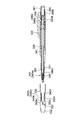
- FIG. 1 is a schematic longitudinal sectional view of the mechanical pencil 100 according to the first embodiment of the present invention.
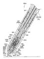
- FIG. 2 shows the mechanical pencil 100 shown in FIG. 1 when no writing pressure is applied to the writing core 70.
- FIG. 3 is a schematic vertical cross-sectional view of the front region, and FIG. 3 is a schematic vertical cross-sectional view of the front region of the mechanical pencil 100 of FIG. 1 when a writing pressure is applied to the writing core 70.
- the mechanical pencil 100 includes a shaft cylinder 10 and a writing core 70 that is supported in the shaft cylinder 10 and whose front region is tiltable in the shaft cylinder 10.
- the shaft cylinder 10 according to the present embodiment is made of polycarbonate, and includes a rear shaft 20 and a front shaft 30 whose rear region is fixed (screwed) to a front region of the rear shaft 20.
- the core feeding unit 40 is fixed to a polypropylene core pipe 41 extending in the axial direction of the shaft tube 10 inside the shaft tube 10 and a front end portion of the core pipe 41 via a connector 49.
- Return spring 44 is fixed to a polypropylene core pipe 41 extending in the axial direction of the shaft tube 10 inside the shaft tube 10 and a front end portion of the core pipe 41 via a connector 49.
- Return spring 44 is provided to a polypropylene core pipe 41 extending in the axial direction of the shaft tube 10 inside the shaft tube 10
- the outer cylinder 45 supports the chuck 43 on the inner peripheral surface of the front region and has a flange portion 45c as an overhanging portion on the outer peripheral surface of the rear region. It has a cylinder 45a and a front cylinder 45b that is fitted and fixed to the front end region of the rear cylinder 45a and extends forward in the axial direction beyond the front end of the chuck 43.
- the flange portion 45 c has a cylindrical wall 45 d at the rear end portion that extends axially rearward with a gap between the flange portion 45 c and the outer peripheral surface of the connector 49.
- a return spring 44 is disposed in a compressed state between the flange portion 45 c and the protrusion 49 a of the connector 49, and the core pipe 41 is axially disposed with respect to the outer cylinder 45. It is energized backward. In this state, the chuck 43 is clamped by the fastening ring 42 so as not to retract the writing core 70. Further, the front cylinder 45 b has an abutting step portion 45 e that restricts the forward movement of the fastening ring 42 in the middle on the inner peripheral surface in the axial direction of the fastening ring 42.
- the shaft cylinder 10 (rear shaft 20) has a protruding portion 21 on the inner peripheral surface in the axial direction rearward than the flange portion 45 c of the outer cylinder 45.
- a coil spring 60 that can be expanded and contracted is disposed in a compressed state between the flange 45c.
- the inner diameter of the rear region of the front shaft 30 is larger than the outer diameter of the flange portion 45c, and a gap is formed between the inner peripheral surface of the front shaft 30 and the outer peripheral surface of the flange portion 45c. As a result, the tilting of the lead feeding unit 40 with respect to the shaft tube 10 is allowed.
- a brass base 52 is attached to the tip region of the lead feeding unit 40.
- the base 52 of the present embodiment is supported on a cylindrical base member 51 made of brass fixed to the front end region of the core feeding unit 40 so as to be relatively movable in the axial direction, and together with the base member 51, the base unit 50. Is configured.
- the base member 51 has a pressed portion 53 at the front end.
- the pressed portion 53 of the present embodiment is configured as a tapered surface having an angle of 25 ° with respect to the axial direction of the shaft tube 10.
- the axial cylinder 10 front axis
- the press part 32 projected over the internal peripheral surface in the front area
- the pressing portion 32 and the pressed portion 53 are in contact with each other.
- the pressing portion 32 moves the pressed portion 53 relative to the shaft tube 10 in the axial direction rearward.
- the spring constant of the coil spring 60 is 800 N / m, and the pressed portion 53 (tapered surface) is moved relative to the axial tube 10 in the rearward direction against the urging force of the coil spring 60.
- the load required for this is 3.4N.
- the base member 51 has the inner diameter of the back region 51b smaller than the inner diameter of the front region 51a, and the front region 51a and the rear region 51b.
- a step portion 54 is formed on the inner peripheral surface of the connecting portion.
- a cylindrical gap is formed between the inner circumferential surface of the front region 51a and the outer circumferential surface of the core feeding unit 40, and a base 52 is inserted into this gap.
- the base 52 includes a pipe-shaped front region 52a for guiding the writing core 70, and a sleeve-shaped rear region 52b having a diameter larger than that of the front region 52a.
- the rear region 52b is inserted into the cylindrical gap.
- the shaft cylinder 10 front shaft 30
- the inner diameter of the shaft 30 is smaller than the outer diameter of the rear region 52 b of the base 52.
- a retractable spring 55 is disposed in a compressed state between the rear end portion of the rear region 52 b of the base 52 and the stepped portion 54 of the base member 51.
- the lead feeding unit 40 further includes a knock portion 48 that is attached to the rear end of the lead pipe 41 and presses the lead pipe 41 forward in the axial direction against the outer cylinder 45. is doing.
- the knock portion 48 of the present embodiment has a sleeve portion 48a that is fitted on the rear end region of the core pipe 41 in the axially forward direction, so that the cylindrical eraser 80 can be removed in the axially rearward direction. It has a holder portion 48b for holding.
- the internal space of the sleeve portion 48a and the internal space of the holder portion 48b are communicated by an opening.
- a dome-shaped knob 81 that covers the back of the eraser 80 is detachably fitted to the holder portion 48b.
- the crown 23 is fixed to the rear end region of the rear shaft 20.
- a step portion 23 a facing rearward in the axial direction is formed on the inner peripheral surface of the head crown 23.
- a flange portion 48c is formed on the outer periphery of the holder portion 48b, and an expandable / contractable spring 48d is disposed in a compressed state between the flange portion 48c and the stepped portion 23a.
- the knob 81 and the eraser 80 are removed from the holder portion 48b, and the writing core 70 is formed through an opening that connects the sleeve portion 48a and the holder portion 48b. It is put into the core pipe 41. Then, the eraser 80 and the knob 81 are attached to the holder portion 48b, and the knock portion 48 (knob 81) is pressed (knocked) forward in the axial direction with the front end of the base 52 directed downward. As a result, the core pipe 41, the connector 49, the chuck 43 and the fastening ring 42 are advanced against the urging force of the return spring 44.
- the core pipe 41 is moved backward together with the chuck 43 by the urging force of the return spring 44.
- the fastening ring 42 is fitted again to the front region of the chuck 43, and the chuck 43 is fastened.
- the writing core 70 is pinched so as not to retreat, and the state where the writing core 70 is extended is maintained.
- the writing core 70 is exposed (drawn out) for a desired length from the tip of the base 52 (see FIG. 2).
- the front shaft 30 is gripped by the user, and writing is performed by moving the shaft tube 10 as desired while bringing the writing core 70 into contact with the paper surface.
- the shaft tube 10 is generally gripped so that the axial direction forms an acute angle with respect to the paper surface (see FIGS. 2 and 3). For this reason, a writing pressure including a component perpendicular to the axial direction of the shaft cylinder 10 and a component in the axial direction is applied to the writing core 70.
- the mechanical pencil 100 of the present embodiment absorbs a component perpendicular to the axial direction of the writing pressure and a component in the axial direction, respectively, from the tip of the base 52. The breakage of the exposed writing core 70 is avoided.
- the front region of the core feeding unit 40 is tilted by a component perpendicular to the axial direction of the writing pressure, and the pressed portion 53 ( The taper surface is pressed rearward in the axial direction.
- the lead feeding unit 40 including the writing lead 70 and the base member 51 is moved relative to the axial tube 10 in the axial direction against the urging force of the coil spring 60.
- the base 52 is pressed forward in the axial direction with respect to the base member 51 by the urging force of the spring 55, it is not moved relative to the axial tube 10 rearward in the axial direction. As a result, the length of the writing core 70 exposed from the tip of the base 52 is reduced.
- the writing core 70 is pressed rearward in the axial direction against the axial tube 10 by the axial component of the writing pressure.
- the lead feeding unit 40 including the writing lead 70 and the base member 51 is further moved relative to the rear in the axial direction against the urging force of the coil spring 60. That is, the length of the writing core 70 exposed from the tip of the base 52 is further reduced, and breakage of the writing core 70 is avoided.
- the core feeding unit 40 including the writing core 70 and the base member 51 is pushed back in the axial direction by the biasing force of the coil spring 60. As a result, the initial state (see FIG. 2) is restored.
- the front region of the core feeding unit 40 is within the shaft tube 10 due to a component perpendicular to the axial direction of the writing pressure. Tilted.
- the lead feeding unit 40 including the writing lead 70 is moved relative to the axial tube 10 in the axial direction against the urging force of the coil spring 60, so that the writing lead 70 exposed from the tip of the base 52 is exposed. Length is reduced. Further, due to the axial component of the writing pressure, the lead feeding unit 40 including the writing lead 70 is further moved relative to the axial tube 10 in the axial direction against the urging force of the coil spring 60, and from the tip of the base 52.
- the length of the exposed writing core 70 is further reduced. For these reasons, when a high writing pressure is applied to the writing core 70, breakage of the writing core 70 is reliably avoided. Further, at this time, the base 52 is not moved relative to the axial tube 10 in the axial direction forward (jumps out), but the lead feeding unit 40 including the writing core 70 is moved relative to the base 52 in the axial direction rearward. As a result, the length of the writing core 70 exposed from the base 52 is reduced. For this reason, when the tip of the base 52 comes into contact with the paper surface, the length of the writing core 70 exposed from the base 52 is quickly increased by the biasing force of the coil spring 60 only by slightly reducing the writing pressure. Therefore, the catch between the tip of the base 52 and the paper surface can be quickly eliminated.
- the pressed portion 53 of the core feeding unit 40 is a tapered surface, and the tapered surface has an angle of 25 ° with respect to the axial direction of the shaft tube 10, and the spring constant of the coil spring 60 is 800 N / m. It is. Necessary for such a combination of the pressed portion 53 and the coil spring 60 to move the pressed portion 53 (tapered surface) relative to the axial tube 10 in the axial rear direction against the urging force of the coil spring 60. The heavy load is 3.4N. For this reason, when a high writing pressure is applied to the writing core 70, the core feeding unit 40 including the writing core 70 is reliably moved relative to the axial tube 10 in the axially rear direction. Is definitely avoided. On the other hand, when an appropriate writing pressure is applied to the writing core 70, the lead feeding unit 40 including the writing core 70 is not substantially moved rearward in the axial direction with respect to the shaft tube 10, so that the writing quality is impaired. There is nothing.
- the lead feeding unit 40 may be bent and deformed instead of tilting. Also in this case, the core feeding unit 40 can be moved relative to the axial tube 10 rearward in the axial direction due to the writing pressure perpendicular to the axial direction of the axial tube 10. This bending deformation can be realized, for example, by configuring the core pipe 41 with a flexible material.
- the base member 51 is provided with a tapered surface that gradually increases in diameter toward the rear in the axial direction as the pressed portion 53, but such a tapered surface serves as the pressing portion 32 in the front shaft. It may be provided in the 30 front area.
- the pressed portion 53 of the base member 51 may be formed as a protruding portion protruding outward in the radial direction of the shaft tube 10, and gradually increases in diameter toward the rear in the axial direction as in the present embodiment. It may be formed as a tapered surface.
- a knock type unit is employed as the core feeding unit 40.
- a swinging type core feeding unit in which the writing core 70 is fed out by shaking the shaft tube 10 back and forth may be employed. .
- a connector 49 is employed in which the protrusion 49 a exceeds the outer diameter of the core pipe 41 and protrudes radially outward of the shaft tube 10, and a space formed between the shaft tube 10 and the core pipe 41.
- the weight body may be loosely fitted around the core pipe 41.
- a weight having a weight of 2.3 g which is formed in a cylindrical shape by winding a wire around the axis of the shaft cylinder 10 can be adopted.
- the weight body moves back and forth inside the space and comes into contact with the protrusion 49a of the connector 49 in the front in the axial direction.
- the connector 49 is advanced in the axial direction by the inertial force of the weight body, and the writing core 70 is drawn out.
- the same effects as those obtained when the knock-type lead feeding unit 40 is employed can be obtained. Furthermore, the writing core 70 can be quickly fed out without performing a knock operation.
- FIG. 4 is a schematic longitudinal sectional view of the mechanical pencil 200 according to the second embodiment of the present invention
- FIG. 5 is a diagram of the mechanical pencil 200 of FIG. 4 when the writing pressure is applied to the writing core 270. It is a schematic longitudinal cross-sectional view of a front area
- the mechanical pencil 200 of the present embodiment is different from the first embodiment in that the flange portion 251 a is not the outer peripheral surface of the rear region of the outer cylinder 45 but the rear of the base member 251. It is provided on the outer peripheral surface of the region.
- a protruding portion 234 that is in contact with the rear end portion of the coil spring 260 is provided not on the rear shaft 220 but on the inner peripheral surface of the front shaft 230 behind the flange portion 251a in the axial direction.
- a weak coil spring 260a and a strong coil spring 260b disposed in the axial direction rearward are connected in series as the expandable and contractible coil spring 260 disposed in a compressed state between the protrusion 234 of the front shaft 230 and the flange 251a. What has been adopted is adopted.
- the spring constant of the weak coil spring 260a is 700 N / m
- the spring constant of the strong coil spring 260b is 1000 N / m.
- the weak coil spring 260a and the strong coil spring 260b are connected via a cylindrical regulating member 261 that regulates the compression length of the weak coil spring 260a.
- the restricting member 261 includes a sleeve portion 261a that covers the outside of the weak coil spring 260a, and an annular portion 261b that is formed integrally with the rear end portion of the sleeve portion 261a. Further, the annular portion 261b includes an inner protruding portion 261c that protrudes radially inward of the shaft tube 210 from the inner wall of the sleeve portion 261a, and an outer protruding portion that protrudes radially outward of the shaft tube 210 from the outer wall of the sleeve portion 261a.
- a weak coil spring 260a is disposed between the flange 251a and the inner protrusion 261c in a compressed state so as to expand and contract, and a strong coil spring 260b is compressed between the inner protrusion 261c and the protrusion 234 so as to expand and contract. Is arranged in.
- a step portion 235 facing rearward in the axial direction is formed in front of the protrusion portion 234 of the front shaft 230 in the axial direction, and the annular portion 261b of the restricting member 261 is axially rearward of the step portion 235. It is slidably fitted in the direction.
- the inner diameter of the shaft cylinder 210 (front shaft 230) is smaller than the outer diameter of the outer protruding portion 261d in the axial direction forward of the step portion 235, and the annular portion 261b exceeds the step portion 235 in the axial direction. It is designed not to slide forward.
- the annular portion 261b of the regulating member 261 is in contact with the stepped portion 235 by the urging force of the strong coil spring 260b. In this state, a gap of, for example, 0.8 mm is formed between the front end portion of the sleeve portion 261a of the restriction member 261 and the rear end portion of the flange portion 251a.
- a load necessary for moving the pressed portion 253 (tapered surface) relative to the axial tube 210 in the axial rearward direction against the urging force of the weak coil spring 260a. Is 2.5N, and the load required to move the pressed portion 253 (tapered surface) relative to the axial tube 210 in the axial direction against the urging force of the strong coil spring 260b is 7N. is there.
- the rear shaft 220 of the present embodiment has a protrusion 222 on the inner peripheral surface of the rear region, and a weight body 290 is provided between the protrusion 222 and the connector 249. Is arranged.
- a weight body 290 a weight having a weight of 2.3 g formed by winding a wire around the axis of the shaft cylinder 210 and forming a cylindrical shape can be used.
- the inner diameter of the rear shaft 220 is smaller than the outer diameter of the weight body 290 at the protruding portion 222.
- the connector 249 has a protrusion on the outer peripheral surface.
- the shaft cylinder 210 is swung back and forth, so that the weight body 290 passes through the space formed between the shaft cylinder 210 and the core pipe 241 in the axial direction forward of the connector 249. It moves back and forth until it comes into contact with the protrusion, and until it comes into contact with the protrusion 222 in the rear in the axial direction.
- the inertia force of the weight body 290 causes the connector 249, the chuck, and the fastening ring to move forward against the urging force of the return spring 244.
- only the fastening ring comes into contact with the contact step formed on the inner peripheral surface of the outer cylinder 245.
- the tightening ring is removed from the chuck in the axial direction rearward, the chuck is released, and the writing core 270 is fed out.
- the connector 249 When the influence of the inertial force of the weight body 290 on the connector 249 is eliminated, the connector 249 is retracted by the urging force of the return spring 244. Along with this, the chuck engaged with the connector 249 is also retracted, and the tightening ring is fitted again in the front region of the chuck, and the chuck is tightened. Thereby, the writing core 270 is pinched so as not to retreat, and the state where the writing core 270 is extended is maintained. The writing core 270 is exposed (drawn out) for a desired length from the tip of the base 252 by appropriately repeating the longitudinal movement of the shaft cylinder 210 as described above.
- the writing core 270 is fed out by pressing (knocking) the knock portion 248 as in the first embodiment.
- an appropriate resistance is provided by the urging force of the spring 248d disposed between the flange portion 248c of the knock portion 248 and the step portion 223a of the head crown 223.
- the front shaft 230 is gripped by the user, and writing is performed by moving the shaft tube 210 as desired while bringing the writing core 270 into contact with the paper surface.
- the mechanical pencil 200 of the present embodiment also has a component perpendicular to the axial direction of the writing pressure and a component in the axial direction when a high writing pressure is applied to the writing core 270 during writing. Each is absorbed to avoid breakage of the writing core 270 exposed from the tip of the base 252.
- the front region of the core feeding unit 240 is tilted by a component perpendicular to the axial direction of the writing pressure, and the pressed portion 253 ( The taper surface is pressed rearward in the axial direction.
- the core feeding unit 240 including the writing core 270 is relatively moved in the axially rearward direction with respect to the axial cylinder 210 against the urging force of the weak coil spring 260a and the strong coil spring 260b.
- the weak coil spring 260a is allowed to be compressed and deformed by, for example, 0.8 mm at the maximum.
- the weak coil spring 260a is compressed and deformed by 0.8 mm, the rear end portion of the flange portion 251a of the base member 251 is brought into contact with the front end portion of the sleeve portion 261a.
- the lead feeding unit 240 is further moved relative to the rear in the axial direction from this state, the base member 251, the lead feeding unit 240, and the movement restricting member 261 are integrated to counter the urging force of the strong coil spring 260 b. Is moved relative to the rear in the axial direction.
- the core is fed out against the biasing force of the weak coil spring 260a due to the difference in the load necessary to cause further compression deformation of the coil springs 260a, 260b arranged in the compressed state.
- a greater sense of resistance is provided than when the unit 240 is moved relatively rearward in the axial direction.
- the base 52 since the base 52 is pressed forward in the axial direction with respect to the base member 251 by the urging force of the spring 255, the base 52 is not moved relative to the axial tube 210 in the rear in the axial direction. As a result, the length of the writing core 270 exposed from the tip of the base 252 is reduced.
- the writing core 270 is pressed rearward in the axial direction with respect to the axial tube 210 by the axial component of the writing pressure.
- the core feeding unit 240 including the writing core 270 and the base member 251 is relatively moved rearward in the axial direction against the urging force of the weak coil spring 260a and the strong coil spring 260b.
- the coil springs 260a and 260b are compressed in the order of the weak coil spring 260a and the strong coil spring 260b.
- the length of the writing core 270 exposed from the tip of the base 252 is further reduced, and breakage of the writing core 270 is avoided.
- FIG. 6 shows an example of the weight at which the drawing core 270 starts to be retracted (retracted) when the angle between the axial direction of the shaft cylinder 210 and the paper surface is 55 °.
- L ⁇ b> 1 is the center line of the shaft cylinder 210
- L ⁇ b> 2 is the center line of the writing core 270 in the state of being fed out from the core feeding unit 240.
- the front region of the core feeding unit 240 tilts in the shaft tube 210 due to a component perpendicular to the axial direction of the writing pressure. Is done.
- the lead feeding unit 240 including the writing lead 270 is moved relative to the axial tube 210 in the axial direction against the urging force of the coil spring 260, so that the writing lead 270 exposed from the tip of the base 252 is removed. Length is reduced.
- the lead feeding unit 240 including the writing lead 270 is further moved relative to the axial tube 210 in the axial rear direction against the urging force of the coil spring 260 by the axial component of the writing pressure, and from the tip of the base 252.
- the length of the exposed writing core 270 is further reduced. For these reasons, when a high writing pressure is applied to the writing core 270, breakage of the writing core 270 is reliably avoided.
- the base 252 is not moved relative to the axial tube 210 in the axial direction forward (projects out), but the lead feeding unit 240 including the writing core 270 is moved relative to the base 252 in the axial rearward direction. As a result, the length of the writing core 270 exposed from the base 252 is reduced.
- the length of the writing core 270 exposed from the base 252 is quickly increased by the biasing force of the coil spring 260 only by slightly reducing the writing pressure. Therefore, the catch between the tip of the base 252 and the paper surface can be quickly eliminated.
- the coil spring 260 of the present embodiment is configured by arranging a weak coil spring 260a having a spring constant of 700 N / m and a strong coil spring 260b having a spring constant of 1000 N / m arranged in series.
- the load required to move the pressed portion 253 (tapered surface) relative to the axial tube 210 in the axial direction rearward against the urging force of the weak coil spring 260a is 2.5 N
- the strong coil spring The load required to move the pressed portion 253 (tapered surface) relative to the shaft cylinder 210 in the axial direction rearward against the urging force of 260b is 7N.
- the pen pressure is absorbed stepwise in this order by the weak coil spring 260a that starts compressive deformation with a relatively small load and the strong coil spring 260b that starts compressive deformation with a relatively large load.
- the resistance feeling due to the urging force of the coil spring 260 when the lead feeding unit 240 including the writing lead 270 is relatively moved axially rearward with respect to the shaft cylinder can be optimized.
- the core feeding unit 240 includes a core pipe 240 extending in the axial direction of the shaft tube 210 inside the shaft tube 210, and a connector 249 that is fixed to the front end portion of the core pipe 240 and has a protrusion formed on the outer peripheral surface.
- a chuck that is fixed to the front end of the connector 249, a fastening ring that is externally fitted to the front region of the chuck, a return spring 244 that biases the connector 249 rearward in the axial direction, a shaft cylinder 210, and a core pipe 241
- a weight body 290 disposed so as to be loosely fitted to the outer periphery of the core pipe 241 in the space formed between the weight pipe 241 and the weight body 290 when the shaft cylinder 210 is swung back and forth. Further, the inside of the space portion is moved back and forth, and comes into contact with the protrusion of the connector 249 in the front. For this reason, since the chuck is advanced in the axial direction by the inertial force of the weight body 290 by swinging the shaft cylinder 210 back and forth, the writing core 270 can be quickly fed out without performing a knocking operation.
- the lead feeding unit 240 may be bent and deformed instead of tilting the lead feeding unit 240. Also in this case, due to the writing pressure perpendicular to the axial direction of the axial tube 210, the core feeding unit 240 can be moved relative to the axial tube 210 rearward in the axial direction. This bending deformation can be realized, for example, by configuring the core pipe 241 with a flexible material.
- the base member 251 is provided with a tapered surface that gradually increases in diameter toward the rear in the axial direction as the pressed portion 253, but such a tapered surface serves as a front shaft as the pressing portion 232. 230 may be provided in the front region.
- the pressed portion 253 of the base member 251 may be formed as an overhanging portion that protrudes outward in the radial direction of the shaft tube 210, or gradually increases in diameter toward the rear in the axial direction as in the present embodiment. It may be formed as a tapered surface.
- FIG. 7 is a schematic longitudinal sectional view of the mechanical pencil 300 according to the third embodiment of the present invention.
- FIG. 8 shows the mechanical pencil 300 of FIG. 7 when the writing pressure is applied to the writing core 370.
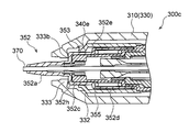
- FIG. 9 is a schematic longitudinal sectional view of the front region, and FIG. 9 is a schematic longitudinal sectional view showing the front region of the mechanical pencil 300 of FIG. 7 in an exploded view.
- the mechanical pencil 300 is arranged at the tip region of the lead feeding unit 340 and can move relative to the lead feeding unit 340 in the axial direction of the axial tube 310.
- the lead feeding unit 340 of the present embodiment includes a lead feeding unit main body 340a whose front end is surrounded by a base 352, a holding member 340b for holding the base 352 in a state of being prevented from being detached from the core feeding unit main body 340a, have.
- the base 352 includes a cylindrical front region 352a for guiding the writing core 370 and a sleeve-like rear region 352b having a diameter larger than that of the front region 352a.
- the rear region 352b has a front small diameter portion 352c and a rear large diameter portion 352d, and the small diameter portion 352c and the large diameter portion 352d are connected by a shoulder portion 352h having a tapered surface 352e on the outer surface. .
- Such a base 352 is attached to the tip region of the core feeding unit main body 340a in a state of being prevented from being detached by the holding member 340b and being slidable in the axial direction of the shaft tube 310.
- the holding member 340 b includes a cylindrical main body 340 c that surrounds the rear region 352 b of the base 352 and an annular shape that is fitted in the rear end region of the main body 340 c. And a stopper 340d.
- the base 352 is held inside the holding member 340b so as to be slidable in the axial direction of the main body 340c, and an undesired drop-off from the main body 340c is prevented.
- the front end of the main body 340c is an opening, and the front region 352a of the base 352 projects forward from the opening.
- a tapered surface is formed on the outer surface of the front region of the main body 340c as a pressed portion 353 that tapers toward the front in the axial direction of the shaft tube 310.
- the inner surface of the main body portion 340c has a reduced diameter portion 340e having an inner diameter smaller than that of other regions of the main body portion 340c.
- a flat surface 345f facing the front in the axial direction is formed on the outer surface of the outer cylinder 345 at the rear side in the axial direction from the reduced diameter portion 340e, and the compression is made between the small diameter portion 352c and the flat surface 345f.
- a state spring 355 is arranged.
- Other configurations are substantially the same as those of the first embodiment. 7 to 9, the same components as those in the first embodiment are denoted by the same reference numerals, and detailed description thereof is omitted.
- the mechanical pencil 300 presses (knocks) the knock portion 348 (knob 381) toward the front in the axial direction in a state where the front end of the base 352 is directed downward. As a result, the writing core 370 is drawn out.
- the front shaft 330 is gripped by the user, and writing is performed by moving the shaft tube 310 as desired while bringing the writing core 370 into contact with the paper surface.
- the mechanical pencil 300 In writing, as described above, it is common that a writing pressure including a component perpendicular to the axial direction of the shaft tube 310 and a component in the axial direction is applied to the writing core 370.
- the mechanical pencil 300 also includes a component perpendicular to the axial direction of the writing pressure and a component in the axial direction when a high writing pressure is applied to the writing core 370 during writing. Each is absorbed to avoid breakage of the writing core 370 exposed from the tip of the base 352.
- the front region of the core feeding unit 340 is tilted by a component perpendicular to the axial direction of the writing pressure, and the pressed portion 353 of the holding member 340 b is moved by the pressing portion 332 of the front shaft 330. It is pressed rearward in the axial direction of the shaft tube 310.
- the lead feeding unit 340 including the writing core 370 is moved relative to the axial tube 310 in the axial direction against the urging force of the coil spring 360.
- the base 352 is biased forward in the axial direction with respect to the holding member 340 b by the spring 355, so that the base 352 is not moved relative to the axial tube 310 rearward in the axial direction.
- the length of the writing core 370 exposed from the tip of the base 352 is reduced.
- the writing core 370 can be pressed rearward in the axial direction against the axial tube 310 by the axial component of the writing pressure.
- the core feeding unit 340 including the writing core 370 is further moved relative to the rear in the axial direction against the urging force of the coil spring 360. That is, the length of the writing core 370 exposed from the tip of the base 352 can be further reduced, and breakage of the writing core 370 can be avoided.
- the core feeding unit 340 including the writing core 370 is pushed back in the axial direction with respect to the shaft tube 310 by the biasing force of the coil spring 360. As a result, the initial state (see FIG. 7) is restored.
- the mechanical pencil 300 of this embodiment has good workability because the base 352 does not undesirably fall out of the lead feeding unit 340 during assembly or disassembly.
- the base 352 of the present embodiment is fitted in the holding member 340b in advance before the front shaft 330 and the rear shaft 320 are screwed together, and in this state
- the stopper 340d is fitted and fixed to the rear end of the main body 340c of the holding member 340b.
- the base 352 is held in the holding member 340b so as to be slidable in the axial direction of the shaft tube 310, and does not undesirably fall off from the holding member 340b.
- the holding member 340 b in which the base 352 is fitted is inserted from the opening at the rear end of the front shaft 330, and the front region 352 a of the base 352 protrudes from the opening at the front end of the front shaft 330. Move forward until you do. Then, the rear shaft 320 assembled with the lead feeding unit 340 is screwed to the front shaft 330.
- the base 352 as described above does not undesirably fall off the holding member 340b even when the mechanical pencil 300 is disassembled during maintenance or the like.
- the front region of the core feeding unit 340 tilts in the shaft tube 310 due to a component perpendicular to the axial direction of the writing pressure. Is done. Thereby, the lead feeding unit 340 including the writing core 370 is moved relative to the axial tube 310 in the axial direction against the urging force of the coil spring 360, so that the writing core 370 exposed from the tip of the base 352 is exposed. Length is reduced.
- the lead feeding unit 340 including the writing lead 370 is further moved axially rearward relative to the shaft tube 310 against the biasing force of the coil spring 360 by the axial component of the writing pressure, and from the tip of the base 352
- the length of the exposed writing core 370 is further reduced. For these reasons, when a high writing pressure is applied to the writing core 370, breakage of the writing core 370 is avoided.
- the base 352 is not moved relative to the axial tube 310 in the axial direction forward (protrudes out), but the lead feeding unit 340 including the writing core 370 is moved relative to the base 352 in the axial rearward direction. As a result, the length of the writing core 370 exposed from the base 352 is reduced.
- the length of the writing core 370 exposed from the base 352 is quickly increased by the biasing force of the coil spring 360 only by slightly reducing the writing pressure. Therefore, the catch between the tip of the base 352 and the paper surface can be quickly eliminated.
- the base 352 of the present embodiment is disposed in the tip region of the core feeding unit 340 and can be moved relative to the core feeding unit 340 in the axial direction of the axial tube 310.
- the lead feeding unit 340 includes a lead feeding unit main body 340a whose front end is surrounded by the base 352, and a holding member 340b for holding the base 352 in a state of being prevented from being detached from the core feeding unit main body 340a. Yes. For this reason, when the mechanical pencil 300 is assembled or disassembled, the base 352 is not undesirably removed from the lead feeding unit 340, and the workability is good.
- the holding member 340b has a cylindrical shape and has a reduced diameter portion 340e on the inner surface, and the base 352 is disposed on the outer surface of the axial tube 310 in the axial direction rearward of the reduced diameter portion 340e.
- An enlarged diameter portion 352d having a diameter larger than the inner diameter is provided.
- the tapered surface as the pressed portion 353 is provided on the holding member 340b, it is easy to provide the pressed portion 353 at a desired position.
- the lead feeding unit 340 is moved rearward in the axial direction with respect to the shaft tube 310.
- a smoother feel can be provided during relative movement.
- the contact portion between the base 352 and the inner flange 333 of the front shaft 330 may be configured to be point contact or line contact. Examples of such mechanical pencils will be described with reference to FIGS. 10 to 12 are schematic longitudinal sectional views partially showing a modification of the mechanical pencil 300 according to the third embodiment of FIG.
- the front region 352a of the base 352 and the small diameter portion 352c are connected by a shoulder portion 352h having a second tapered surface 352g on the outer surface.
- the second tapered surface 352g has a large diameter toward the rear in the axial direction of the shaft tube 310, and forms an angle ⁇ with respect to a plane orthogonal to the axial direction of the shaft tube 310 as shown in the figure.
- the angle ⁇ is preferably any value in the range of 5 ° to 20 °, more preferably any value in the range of 8 ° to 15 °, more preferably 10 ° to 13 °. It is more preferable that the value is any value within the range.
- the angle ⁇ in the present embodiment is 11.31 °.
- the front shaft 330 has an inner flange 333 projecting inward in the radial direction of the shaft tube 310 in front of the second tapered surface 352g in the axial direction of the shaft tube 310.
- a region of the inner flange 333 facing the second tapered surface 352 g has a plane orthogonal to the axial direction of the shaft tube 310.
- the inner flange 333 is in contact with the second tapered surface 352g only in the radially inner region. Since other configurations are the same as those of the third embodiment, detailed description thereof is omitted.
- the mechanical pencil 300a has a very small contact area between the inner flange 333 and the second tapered surface 352g. For this reason, when the second tapered surface 352g is not provided on the shoulder portion 352h, that is, when the angle ⁇ is 0 °, the frictional force acting between the inner flange 333 and the second tapered surface 352g. Will be greatly reduced. Therefore, the operation when the front area of the lead feeding unit 340 is tilted by the component perpendicular to the axial direction of the writing pressure becomes smooth. As a result, a smooth feel is provided when the lead feeding unit 340 including the writing lead 370 moves relatively rearward in the axial direction with respect to the shaft tube 310.
- the angle ⁇ is not so large as 11.31 °, when the core feeding unit 340 moves relative to the axial tube 310 rearward in the axial direction, the base 352 can move greatly rearward in the axial direction. Since there is no writing feeling, the writing feeling is not greatly reduced.
- the second taper surface 352g is provided on the base 352 so that the frictional force acting between the inner flange 333 and the base 352 is reduced, but the inner flange 333 is not the base 352.
- the frictional force may be reduced. 11 and 12 show such a modification.
- the shoulder portion 352h of the base 352 is configured to have a plane orthogonal to the axial direction of the shaft tube 310 instead of the second tapered surface 352g.
- a protrusion 333a that protrudes rearward in the axial direction is formed in a region of the inner collar 333 facing the shoulder portion 352h.
- the protrusion 333a may be a protrusion formed continuously or intermittently in the circumferential direction of the inner flange 333, or a plurality of point-like protrusions provided at intervals in the circumferential direction of the inner flange 333. It may be. With such a configuration, the inner collar 333 is in contact with the shoulder portion 352h of the base 352 only at the tip of the protrusion 333a. Since other configurations are the same as those of the third embodiment, detailed description thereof is omitted.
- the contact area between the inner collar 333 and the shoulder 352h can be made extremely small.
- the frictional force acting between the inner collar 333 and the shoulder 352h is greatly reduced. Therefore, when the mechanical pencil 300b is used, the operation when the front area of the lead feeding unit 340 is tilted by the component perpendicular to the axial direction of the writing pressure becomes smooth.
- a smooth feel is provided when the lead feeding unit 340 including the writing lead 370 moves relatively rearward in the axial direction with respect to the shaft tube 310.
- the mechanical pencil 300c according to the modified example of FIG. 12 is configured such that the shoulder portion 352h of the base 352 has a plane orthogonal to the axial direction of the axial tube 310, similarly to the mechanical pencil 300b according to the modified example of FIG. ing.
- the inner flange 333 has a third tapered surface 333b having a large diameter toward the front in the axial direction of the shaft tube 310 in a region facing the shoulder portion 352h.
- the surface of the inner collar 333 that faces the shoulder portion 352 h is inclined such that the radially inner region of the shaft tube 310 is positioned rearward in the axial direction of the shaft tube 310.
- the contact area between the inner collar 333 and the shoulder 352h can be made extremely small.
- the frictional force acting between the inner collar 333 and the shoulder 352h is greatly reduced. Therefore, when the mechanical pencil 300c is used, the operation when the front area of the lead feeding unit 340 is tilted by a component perpendicular to the axial direction of the writing pressure becomes smooth.
- a smooth feel is provided when the lead feeding unit 340 including the writing lead 370 moves relatively rearward in the axial direction with respect to the shaft tube 310.
- the lead feeding unit 340 may be bent and deformed instead of tilting. Also in this case, due to the writing pressure perpendicular to the axial direction of the shaft tube 310, the core feeding unit 340 can be moved relative to the shaft tube 310 rearward in the axial direction. This bending deformation can be realized, for example, by configuring the core pipe 341 with a flexible material.
- a swing-type core feeding unit can be adopted.
Landscapes
- Mechanical Pencils And Projecting And Retracting Systems Therefor, And Multi-System Writing Instruments (AREA)
Abstract
軸筒と、前方領域が前記軸筒内において撓み変形可能あるいは傾動可能であるように後方領域が軸筒内に支持された、筆記芯を繰り出すための芯繰出ユニットと、芯繰出ユニットと軸筒との間に圧縮状態で配置された伸縮可能な弾性体と、を備え、芯繰出ユニットは前方領域の外周面に被押圧部を有し、軸筒は前方領域に押圧部を有し、押圧部と被押圧部との少なくとも一方は、軸方向後方に向かって次第に大径となるテーパ面であり、芯繰出ユニットの前方領域が軸筒内において撓み変形あるいは傾動する前においては、押圧部と被押圧部とが互いに当接しており、芯繰出ユニットの前方領域が軸筒内において撓み変形あるいは傾動する際には、押圧部が被押圧部を軸筒に対して軸方向後方に相対移動させるようになっていることを特徴とするシャープペンシルである。
Description
本発明は、ノック操作等により筆記芯を所定量だけ口金の先端から繰り出すことにより筆記が可能なシャープペンシルに関する。
従来より、シャープペンシルを用いて筆記を行う際に筆記芯に高い筆圧が加えられると、口金の先端から露出された筆記芯が容易に折損してしまう、という問題があった。筆記芯の折損は、筆圧が一定であれば、シャープペンシルの軸筒の軸方向と紙面とのなす角度が小さくなるほど(軸筒を寝かせるほど)、あるいは、口金の先端から露出される筆記芯の長さが長くなるほど、顕著である。
このような問題に対し、特許文献1(特開2015-123689)には、筆記芯に高い筆圧が加えられた際に、筆圧の軸方向の成分と筆圧の当該軸方向に垂直な成分とをそれぞれ異なる機構により吸収して筆記芯の折損を低減させる、というシャープペンシルが記載されている。
具体的には、特許文献1のシャープペンシルは、口金が弾性体(コイルバネ)を介して軸筒に支持されており、当該口金は、軸方向後方に向かって次第に小径となるカム斜面を有している。また、軸筒には、カム斜面を軸方向前方に押圧する押圧部が形成されている。このような構成により、筆圧の軸方向に垂直な成分(軸筒径外方向の力)に起因して、口金のカム斜面が軸筒の押圧部によって軸方向前方に押圧されて、軸筒の先端から口金が前方にスライドする(飛び出す)。これにより、口金の先端から露出される筆記芯の長さが減少されるようになっている。
更に、特許文献1のシャープペンシルは、筆記芯を繰り出す芯繰出ユニットが、弾性体(コイルバネ)によって軸方向前方(軸方向における口金の先端方向)に付勢された状態で、軸方向に相対移動可能に軸筒に支持されている。そして、筆記芯を含む芯繰出ユニットが軸筒に対して軸方向後方に相対移動することによって、筆圧の軸方向の成分が吸収される。この結果、口金の先端から露出される筆記芯の長さが一層減少されて、筆記芯の折損が低減されるようになっている。
更に、特許文献1のシャープペンシルは、筆記芯を繰り出す芯繰出ユニットが、弾性体(コイルバネ)によって軸方向前方(軸方向における口金の先端方向)に付勢された状態で、軸方向に相対移動可能に軸筒に支持されている。そして、筆記芯を含む芯繰出ユニットが軸筒に対して軸方向後方に相対移動することによって、筆圧の軸方向の成分が吸収される。この結果、口金の先端から露出される筆記芯の長さが一層減少されて、筆記芯の折損が低減されるようになっている。
特許文献1に記載されているシャープペンシルでは、筆記芯に高い筆圧が加えられた際に、軸筒に対して口金が前方にスライドできる最大の長さ(ストローク)に亘って当該口金が一気にスライドする(飛び出す)ようになっている。
これに対して、本件発明者は、筆記芯に高い筆圧が加えられた際に、口金に対して筆記芯が後方にスライドする構成を開発し、そのような構成の方が筆記感が滑らかであると感じる使用者が多いことを確認した。
本発明は、以上のような知見に基づいており、その目的は、筆記芯に高い筆圧が加えられた際に当該筆記芯の折損を確実に回避することができると共に、筆記感が滑らかなシャープペンシルを提供することである。
本発明は、軸筒と、前方領域が前記軸筒内において撓み変形可能あるいは傾動可能であるように後方領域が前記軸筒内に支持された、筆記芯を繰り出すための芯繰出ユニットと、前記芯繰出ユニットの前方領域の外周面に設けられた張出部と、前記軸筒の前記張出部よりも軸方向後方の内周面に設けられた突出部と、前記張出部と前記突出部との間に圧縮状態で配置された伸縮可能な弾性体と、を備え、前記芯繰出ユニットは、前方領域の外周面に被押圧部を有しており、前記軸筒は、前方領域に押圧部を有しており、前記押圧部と前記被押圧部との少なくとも一方は、軸方向後方に向かって次第に大径となるテーパ面であり、前記芯繰出ユニットの前方領域が前記軸筒内において撓み変形あるいは傾動する前においては、前記押圧部と前記被押圧部とが互いに当接しており、前記芯繰出ユニットの前方領域が前記軸筒内において撓み変形あるいは傾動する際には、前記押圧部が前記被押圧部を当該軸筒に対して軸方向後方に相対移動させるようになっていることを特徴とするシャープペンシルである。
本発明によれば、筆記芯に高い筆圧が加えられた際に、筆圧の軸方向に垂直な成分によって、芯繰出ユニットの前方領域が軸筒内において撓み変形あるいは傾動される。これにより、筆記芯を含む芯繰出ユニットが弾性体の付勢力に対抗して軸筒に対して軸方向後方に相対移動されるため、口金の先端から露出される筆記芯の長さが減少される。更に、筆圧の軸方向の成分によって、筆記芯を含む芯繰出ユニットが弾性体の付勢力に対抗して軸筒に対して軸方向後方に更に相対移動され、口金の先端から露出される筆記芯の長さが一層減少される。これらのことにより、筆記芯に高い筆圧が加えられた際に当該筆記芯の折損が確実に回避される。また、この時、口金が軸筒に対して軸方向前方に相対移動される(飛び出す)のではなく、筆記芯を含む芯繰出ユニットが口金に対して軸方向後方に相対移動されることによって、当該口金から露出される筆記芯の長さが減少される。このことにより、筆記感が滑らかなシャープペンシルを提供することができる。
好ましくは、前記芯繰出ユニットの前記被押圧部が前記テーパ面であり、当該テーパ面は、前記軸筒の軸方向に対して20°~60°の間のいずれかの角度を有しており、前記弾性体は、コイルバネであり、当該コイルバネによる付勢力に対抗して前記被押圧部を前記軸筒に対して軸方向後方に相対移動させるために必要な荷重は、0.5N~8Nの間のいずれかの値である。
この場合、筆記芯に高い筆圧が加えられた際に、筆記芯を含む芯繰出ユニットが軸筒に対して軸方向後方に確実に相対移動され得るため、筆記芯の折損が確実に回避される。一方、筆記芯に適正な筆圧が加えられている際に、筆記芯を含む芯繰出ユニットが軸筒に対して軸方向後方に実質的に相対移動されないため、書き味を損ねることが無い。
あるいは、好ましくは、前記芯繰出ユニットの前記被押圧部が前記テーパ面であり、当該テーパ面は、前記軸筒の軸方向に対して20°~60°の間のいずれかの角度を有しており、前記弾性体は、第1コイルバネと第2コイルバネとが直列に配置されて構成されており、前記第1コイルバネによる付勢力に対抗して前記被押圧部を前記軸筒に対して軸方向後方に相対移動させるために必要な荷重は、0.5N~5Nの間のいずれかの値であり、前記第2コイルバネによる付勢力に対抗して前記被押圧部を前記軸筒に対して軸方向後方に相対移動させるために必要な荷重は、2N~10Nの間のいずれかの値である。
この場合、相対的に小さな荷重で圧縮変形が開始する第1コイルバネ及び相対的に大きな荷重で圧縮変形が開始する第2コイルバネによって、この順序で段階的に筆圧が吸収されるため、筆記芯を含む芯繰出ユニットが軸筒に対して軸方向後方に相対移動される際の弾性体の付勢力による抵抗感を、最適化することができる。
また、好ましくは、前記芯繰出ユニットは、前記軸筒の内部で当該軸筒の軸方向に延在する芯パイプと、前記芯パイプの前端部に固定され外周面に突部が形成されたコネクタと、前記コネクタの前端部に固定されたチャックと、前記チャックの前方領域に外嵌された締めリングと、前記コネクタを軸方向後方に付勢するリターンスプリングと、前記軸筒と前記芯パイプとの間に形成された空間部において当該芯パイプの外周に遊嵌するように配設された重量体と、を有しており、前記重量体は、前記軸筒が前後に振られた際に前記空間部の内部を前後動して、前方において前記コネクタの前記突部に当接するようになっている。
この場合、軸筒を前後に振ることにより重量体の慣性力によってチャックが軸方向に前進させられるため、ノック操作を行うことなく迅速に筆記芯を繰り出すことができる。
以上のようなシャープペンシルは、好ましくは、前記芯繰出ユニットの先端領域に配置され、当該芯繰出ユニットに対して前記軸筒の軸方向に相対移動可能な口金を更に備え、前記芯繰出ユニットは、前記口金によって前端部が取り囲まれた芯繰出ユニット本体と、前記口金を当該芯繰出ユニット本体に抜け止め状態で保持するための保持部材と、を有している。
この場合、シャープペンシルの組立時や分解時において、口金が不所望に芯繰出ユニットから抜け落ちることがないため、作業性が良好である。
好ましくは、前記保持部材は、筒状であり、内面に縮径部を有しており、前記口金は、前記縮径部よりも前記軸筒の軸方向後方の外面に、当該縮径部の内径よりも大径の拡径部を有している。この場合、前記芯繰出ユニットからの前記口金の抜け落ちが確実に防止される。
より好ましくは、前記被押圧部は、前記保持部材に設けられている。この場合、被押圧部(テーパ面)を所望の位置に設けることが容易である。
また、好ましくは、前記口金は、前記軸筒の前端から外方に突出し、前記芯繰出ユニットから繰り出される前記筆記芯を取り囲む、筒状の前方領域と、前記前方領域の、前記軸筒の軸方向後方に設けられ、当該軸筒の径方向外方に広がる肩部と、を有し、前記軸筒は、前記肩部よりも前記軸筒の軸方向前方に当該軸筒の径方向内方に張り出した内鍔を有し、前記肩部と前記内鍔とは、点接触または線接触している。
この場合、軸筒の内鍔と口金の肩部との接触面積を極めて小さくすることができ、口金が軸筒に対してスムーズに移動することができる。このことにより、筆記芯を含む芯繰出ユニットが軸筒に対して軸方向後方に相対移動する際に滑らかな感触を提供することができる。
具体的には、前記口金は、前記軸筒の前端から外方に突出し、前記芯繰出ユニットから繰り出される前記筆記芯を取り囲む、筒状の前方領域と、前記前方領域の、前記軸筒の軸方向後方に設けられ、当該軸筒の径方向外方に広がる肩部と、を有し、前記軸筒は、前記肩部よりも前記軸筒の軸方向前方に当該軸筒の径方向内方に張り出した内鍔を有し、前記肩部は、前記軸筒の軸方向後方に向かって大径となる第2テーパ面であり、前記内鍔と前記第2テーパ面とが互いに当接している。
この場合、好ましくは、前記第2テーパ面は、前記軸筒の軸方向と直交する平面に対して、5°以上20°以下の角度を有している。この場合、良好な筆記感を提供しつつ、口金が軸筒に対して特にスムーズに移動することができる。すなわち、この角度が5°以上であれば、軸筒の内鍔と口金の肩部との摩擦抵抗が小さく、軸筒の径方向における口金のスムーズな移動が実現される。一方、この角度が20°よりも小さければ、筆記芯を含む芯繰出ユニットが軸筒に対して軸方向後方に相対移動する際に、口金が当該軸方向後方に大きく移動することが無く、筆記感の低下を回避することができる。
あるいは、前記内鍔は、前記軸筒の軸方向後方に向かって突出し前記肩部に当接する突起を有し、前記突起と前記肩部とが互いに当接していても良い。
この場合も、内鍔と肩部との接触面積を極めて小さくすることができ、口金が軸筒に対してスムーズに移動することができる。このことにより、筆記芯を含む芯繰出ユニットが軸筒に対して軸方向後方に相対移動する際に滑らかな感触を提供することができる。
あるいは、前記内鍔は、前記肩部に面する領域に、前記軸筒の軸方向前方に向かって大径となる第3テーパ面を有していても良い。
この場合、第3テーパ面の存在によって、軸筒の径方向内方の領域に口金の肩部に向かって突出した突起が形成されている。このため、内鍔と肩部との接触面積を極めて小さくすることができ、口金が軸筒に対してスムーズに移動することができる。このことにより、筆記芯を含む芯繰出ユニットが軸筒に対して軸方向後方に相対移動する際に滑らかな感触を提供することができる。
以下に、添付の図面を参照して本発明の第1の実施の形態を詳細に説明する。
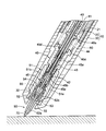
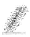
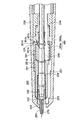
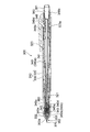
図1は、本発明の第1の実施の形態のシャープペンシル100の概略縦断面図であり、図2は、筆記芯70に筆圧が加えられていない場合の、図1のシャープペンシル100の前方領域の概略縦断面図であり、図3は、筆記芯70に筆圧が加えられている場合の、図1のシャープペンシル100の前方領域の概略縦断面図である。
本実施の形態のシャープペンシル100は、図1乃至図3に示すように、軸筒10と、軸筒10内に支持され、前方領域が当該軸筒10内において傾動可能な、筆記芯70を繰り出すための芯繰出ユニット40と、を備えている。本実施の形態の軸筒10は、ポリカーボネート製であり、後軸20と、後方領域が後軸20の前方領域に固定(螺着)された前軸30と、により構成されている。
本実施の形態の芯繰出ユニット40は、軸筒10の内部で当該軸筒10の軸方向に延在するポリプロピレン製の芯パイプ41と、芯パイプ41の前端部にコネクタ49を介して固定された黄銅製のチャック43と、チャック43の前方領域に外嵌された黄銅製の締めリング42と、チャック43を取り囲む外筒45と、外筒45に対して芯パイプ41を軸方向後方に付勢するリターンスプリング44と、を有している。
具体的には、図2及び図3に示すように、外筒45は、前方領域の内周面においてチャック43を支持すると共に後方領域の外周面に張出部としてのフランジ部45cを有する後筒45aと、後筒45aの前端領域に外嵌固定されチャック43の前端部を超えて軸方向前方に延在する前筒45bと、を有している。また、フランジ部45cは、後端部に、コネクタ49の外周面との間に隙間をもって軸方向後方に延びる円筒壁45dを有している。この円筒壁45dとコネクタ49との隙間において、フランジ部45cとコネクタ49の突部49aとの間にリターンスプリング44が圧縮状態で配置されており、外筒45に対して芯パイプ41を軸方向後方に付勢している。この状態で、チャック43は、締めリング42によって締められて筆記芯70を後退しないように挟持している。更に、前筒45bは、締めリング42よりも軸方向前方の内周面に当該締めリング42の前進を途中で規制する当接段部45eを有している。
また、図1に示すように、軸筒10(後軸20)は、外筒45のフランジ部45cよりも軸方向後方の内周面に突出部21を有しており、この突出部21とフランジ部45cとの間に、伸縮可能なコイルバネ60が圧縮状態で配置されている。このような構成により、筆記芯70を含む芯繰出ユニット40は、コイルバネ60の付勢力に対抗して軸筒10に対して軸方向後方への相対移動が可能となっている。
また、前軸30の後方領域の内径は、フランジ部45cの外径よりも大きくなっており、前軸30の内周面とフランジ部45cの外周面との間に隙間が形成されている。このことにより、軸筒10に対する芯繰出ユニット40の傾動が許容されている。
また、芯繰出ユニット40の先端領域には、黄銅製の口金52が取り付けられている。本実施の形態の口金52は、芯繰出ユニット40の前端領域に固定された黄銅製の筒状のベース部材51に軸方向に相対移動可能に支持されており、当該ベース部材51と共に口金ユニット50を構成している。
ベース部材51は、前端部に被押圧部53を有している。本実施の形態の被押圧部53は、軸筒10の軸方向に対して25°の角度を有するテーパ面として構成されている。また、軸筒10(前軸30)は、前方領域に内周面に張り出した押圧部32を有している。本実施の形態では、図2に示すように、芯繰出ユニット40が傾動する前においては、押圧部32と被押圧部53とが互いに当接している。そして、図3に示すように、芯繰出ユニット40が傾動する際に、押圧部32が被押圧部53を軸筒10に対して軸方向後方に相対移動させるようになっている。本実施の形態では、コイルバネ60のバネ定数は800N/mであり、当該コイルバネ60による付勢力に対抗して被押圧部53(テーパ面)を軸筒10に対して軸方向後方に相対移動させるために必要な荷重は、3.4Nである。
また、本実施の形態では、図1乃至図3に示すように、ベース部材51は、前方領域51aの内径よりも後方領域51bの内径の方が小さくなっており、前方領域51aと後方領域51bとの接続部分の内周面に段部54が形成されている。前方領域51aの内周面と芯繰出ユニット40の外周面との間には円筒状の隙間が形成されており、この隙間に、口金52が挿入されている。
具体的には、図2及び図3に示すように、口金52は、筆記芯70を案内するパイプ状の前方領域52aと、当該前方領域52aよりも大径のスリーブ状の後方領域52bと、によって構成されており、当該後方領域52bが前記円筒状の隙間に挿入されている。更に、軸筒10(前軸30)は、口金52の後方領域52bの前端部よりも軸方向前方の内周面に内鍔33を有しており、この内鍔33において軸筒10(前軸30)の内径が口金52の後方領域52bの外径よりも小さくなっている。すなわち、この内鍔33と口金52の後方領域52bとが当接して軸筒10に対する口金52の軸方向前方への相対移動が規制され、芯繰出ユニット40の抜けが防止されている。この状態で、口金52の後方領域52bの後端部とベース部材51の段部54との間に、伸縮可能なスプリング55が圧縮状態で配置されている。このような構成により、芯繰出ユニット40が軸筒10に対して軸方向後方に相対移動された際にも、口金52と軸筒10の内鍔33との当接状態が維持されるようになっている。これにより、筆記芯70を含む芯繰出ユニット40が軸筒10に対して軸方向後方に相対移動された際に、口金52の前端部から露出される筆記芯70の長さが減少されるようになっている。
また、図1に示すように、芯繰出ユニット40は、芯パイプ41の後端に取り付けられて芯パイプ41を外筒45に対して軸方向前方に押圧するためのノック部48を、更に有している。本実施の形態のノック部48は、軸方向前方に、芯パイプ41の後端領域に外嵌されるスリーブ部48aを有しており、軸方向後方に円柱状の消しゴム80を取外可能に保持するホルダ部48bを有している。スリーブ部48aの内部空間とホルダ部48bの内部空間とは、開口によって連通されている。このことにより、消しゴム80をホルダ部48bから取り外すことによって、当該開口から筆記芯70を芯ホルダ41内に投入できるようになっている。また、ホルダ部48bには、消しゴム80の後方を覆うドーム状のノブ81が取外可能に外嵌されている。
更に、本実施の形態では、後軸20の後端領域に頭冠23が固定されている。頭冠23の内周面には軸方向後方に面した段部23aが形成されている。また、ホルダ部48bの外周にフランジ部48cが形成されており、このフランジ部48cと段部23aとの間に、伸縮可能なスプリング48dが圧縮状態で配置されている。
次に、本発明の第1の実施の形態のシャープペンシル100の作用について説明する。
まず、紙面に対して筆記を行うに先立ち、必要に応じて、ノブ81と消しゴム80とがホルダ部48bから取り外され、スリーブ部48aとホルダ部48bとを連通する開口を介して筆記芯70が芯パイプ41内に投入される。そして、消しゴム80とノブ81とがホルダ部48bに取り付けられ、口金52の前端が下方に向けられた状態でノック部48(ノブ81)が軸方向前方に向かって押圧(ノック)される。これにより、芯パイプ41、コネクタ49、チャック43及び締めリング42がリターンスプリング44の付勢力に対抗して前進させられる。この前進の途中で、締めリング42のみが外筒45の前筒45bに形成された当接段部45eに当接する。これにより、チャック43から締めリング42が後方に外され、当該チャック43が開放されて筆記芯70が繰り出される。押圧(ノック)時には、ノック部48のフランジ部48cと頭冠23の段部23aとの間に配置されたスプリング48dの付勢力によって、適度な抵抗感がもたらされる。
そして、ノック部48(ノブ81)の押圧状態が解除されると、芯パイプ41がチャック43と共にリターンスプリング44の付勢力によって後退させられる。これに伴って、締めリング42が再びチャック43の前方領域に外嵌され、チャック43が締められる。これにより、筆記芯70が後退しないように挟持され、筆記芯70が繰り出された状態が維持される。そして、この一連の押圧操作が適宜繰り返されることにより、口金52の先端から筆記芯70が所望の長さ露出される(繰り出される)(図2参照)。そして、使用者によって前軸30が把持され、紙面に対して筆記芯70を当接させつつ軸筒10を所望に移動させることによって、筆記が行われる。
筆記の際、軸筒10は、その軸方向が紙面に対して鋭角をなす(図2および図3参照)ように把持されることが一般的である。このため、筆記芯70には、軸筒10の軸方向に垂直な成分と当該軸方向の成分とを含む筆圧が加えられる。本実施の形態のシャープペンシル100は、筆記時に筆記芯70に高い筆圧が加えられると、筆圧の軸方向に垂直な成分と軸方向の成分とをそれぞれ吸収して、口金52の先端から露出された筆記芯70の折損を回避する。
具体的には、図3に示すように、筆圧の軸方向に垂直な成分によって芯繰出ユニット40の前方領域が傾動し、前軸30の押圧部32によってベース部材51の被押圧部53(テーパ面)が軸方向後方に押圧される。これにより、コイルバネ60の付勢力に対抗して、筆記芯70及びベース部材51を含む芯繰出ユニット40が軸筒10に対して軸方向後方に相対移動される。一方、口金52は、スプリング55の付勢力によってベース部材51に対して軸方向前方に押圧されているため、軸筒10に対して軸方向後方には相対移動されない。これらのことにより、口金52の先端から露出される筆記芯70の長さが減少される。
これと同時に、図3に示すように、筆圧の軸方向の成分によって、筆記芯70が軸筒10に対して軸方向後方に押圧される。これにより、コイルバネ60の付勢力に対抗して、筆記芯70及びベース部材51を含む芯繰出ユニット40が軸方向後方に更に相対移動される。すなわち、口金52の先端から露出される筆記芯70の長さが一層減少され、当該筆記芯70の折損が回避される。
そして、筆記芯70に加えられている筆圧が弱められると、コイルバネ60の付勢力によって、筆記芯70及びベース部材51を含む芯繰出ユニット40が軸方向前方に押し戻される。これにより、初期状態(図2参照)が復元される。
以上のような本実施の形態によれば、筆記芯70に高い筆圧が加えられた際に、筆圧の軸方向に垂直な成分によって、芯繰出ユニット40の前方領域が軸筒10内において傾動される。これにより、筆記芯70を含む芯繰出ユニット40がコイルバネ60の付勢力に対抗して軸筒10に対して軸方向後方に相対移動されるため、口金52の先端から露出される筆記芯70の長さが減少される。更に、筆圧の軸方向の成分によって、筆記芯70を含む芯繰出ユニット40がコイルバネ60の付勢力に対抗して軸筒10に対して軸方向後方に更に相対移動され、口金52の先端から露出される筆記芯70の長さが一層減少される。これらのことにより、筆記芯70に高い筆圧が加えられた際に当該筆記芯70の折損が確実に回避される。また、この時、口金52が軸筒10に対して軸方向前方に相対移動される(飛び出す)のではなく、筆記芯70を含む芯繰出ユニット40が口金52に対して軸方向後方に相対移動されることによって、口金52から露出される筆記芯70の長さが減少される。このため、口金52の先端と紙面とが当接した際には、筆圧をわずかに弱めるだけでコイルバネ60の付勢力によって口金52から露出される筆記芯70の長さが速やかに増大されるため、口金52の先端と紙面との引っ掛かりを速やかに解消することができる。
また、芯繰出ユニット40の被押圧部53がテーパ面であり、当該テーパ面は、軸筒10の軸方向に対して25°の角度を有しており、コイルバネ60のバネ定数は800N/mである。このような被押圧部53とコイルバネ60との組合せにより、当該コイルバネ60による付勢力に対抗して被押圧部53(テーパ面)を軸筒10に対して軸方向後方に相対移動させるために必要な荷重は、3.4Nである。このため、筆記芯70に高い筆圧が加えられた際に、筆記芯70を含む芯繰出ユニット40が軸筒10に対して軸方向後方に確実に相対移動されるため、筆記芯70の折損が確実に回避される。一方、筆記芯70に適正な筆圧が加えられている際に、筆記芯70を含む芯繰出ユニット40が軸筒10に対して軸方向後方に実質的に相対移動されないため、書き味を損ねることが無い。
なお、芯繰出ユニット40が傾動するのではなく、当該芯繰出ユニット40が撓み変形するようになっていても良い。この場合も、軸筒10の軸方向に垂直な筆圧に起因して、芯繰出ユニット40を当該軸筒10に対して軸方向後方へ相対移動させることができる。この撓み変形は、例えば芯パイプ41を可撓性の材料で構成することにより、実現することができる。
また、本実施の形態では、ベース部材51に、被押圧部53として軸方向後方に向かって次第に大径となるテーパ面が設けられていたが、このようなテーパ面が押圧部32として前軸30の前方領域に設けられていても良い。この場合、ベース部材51の被押圧部53は、軸筒10の径方向外側に張り出した張出部として形成されても良いし、本実施の形態のように軸方向後方に向かって次第に大径となるテーパ面として形成されても良い。
また、本実施の形態では、芯繰出ユニット40としてノック式のものが採用されたが、軸筒10を前後に振ることによって筆記芯70が繰り出される振出式の芯繰出ユニットが採用されても良い。
この場合、突部49aが芯パイプ41の外径を超えて軸筒10の径方向外側に突出したコネクタ49が採用されると共に、軸筒10と芯パイプ41との間に形成された空間部において芯パイプ41の外周に重量体を遊嵌させればよい。重量体としては、例えば軸筒10の軸線周りにワイヤを巻回して円筒状に形成された重さ2.3gのものが採用され得る。この場合、軸筒10が前後に振られた際に、重量体が前記空間部の内部を前後動して、軸方向前方においてコネクタ49の突部49aに当接する。そして、その当接の際に、コネクタ49が重量体の慣性力によって軸方向に前進させられ、筆記芯70が繰り出される。
このような振出式の芯繰出ユニットを採用しても、ノック式の芯繰出ユニット40を採用した場合と同様の効果を得ることができる。更に、ノック操作を行うことなく迅速に筆記芯70を繰り出すことができる。
次に、図4及び図5を参照して、本発明の第2の実施の形態のシャープペンシル200について説明する。
図4は、本発明の第2の実施の形態のシャープペンシル200の概略縦断面図であり、図5は、筆記芯270に筆圧が加えられている場合の、図4のシャープペンシル200の前方領域の概略縦断面図である。図4及び図5に示すように、本実施の形態のシャープペンシル200は、第1の実施の形態と異なり、フランジ部251aが、外筒45の後方領域の外周面ではなくベース部材251の後方領域の外周面に設けられている。また、コイルバネ260の後端部に当接される突出部234が、フランジ部251aよりも軸方向後方において、後軸220ではなく前軸230の内周面に設けられている。そして、前軸230の突出部234とフランジ部251aとの間に圧縮状態で配置された伸縮可能なコイルバネ260として、弱コイルバネ260aとその軸方向後方に配置された強コイルバネ260bとが直列に接続されたものが採用されている。本実施の形態では、弱コイルバネ260aのバネ定数は、700N/mであり、強コイルバネ260bのバネ定数は、1000N/mである。
弱コイルバネ260aと強コイルバネ260bとは、弱コイルバネ260aの圧縮長さを規制する円筒状の規制部材261を介して接続されている。この規制部材261は、弱コイルバネ260aの外側を覆うスリーブ部261aと、スリーブ部261aの後端部に一体的に形成された環状部261bと、を有している。更に、環状部261bは、スリーブ部261aの内壁よりも軸筒210の径方向内側に突出した内側突出部261cと、スリーブ部261aの外壁よりも軸筒210の径方向外側に突出した外側突出部261dと、を有している。本実施の形態では、内側突出部261cの内周面と芯繰出ユニット240の外周面との間に隙間が形成されており、芯繰出ユニット240が傾動した際に当該芯繰出ユニット240と規制部材261との干渉が回避されるようになっている。そして、フランジ部251aと内側突出部261cとの間に弱コイルバネ260aが伸縮可能に圧縮状態で配置されており、内側突出部261cと突出部234との間に強コイルバネ260bが伸縮可能に圧縮状態で配置されている。
また、前軸230の突出部234よりも軸方向前方には、軸方向後方に面した段部235が形成されており、この段部235の軸方向後方に規制部材261の環状部261bが軸方向に摺動可能に内嵌されている。また、段部235よりも軸方向前方において、軸筒210(前軸230)の内径は、外側突出部261dの外径よりも小さくなっており、環状部261bが段部235を超えて軸方向前方へ摺動しないようになっている。本実施の形態では、筆記芯270に筆圧が加えられていない場合には、規制部材261の環状部261bは、強コイルバネ260bの付勢力によって、段部235に当接されている。この状態において、規制部材261のスリーブ部261aの前端部とフランジ部251aの後端部との間に、例えば0.8mmの隙間が形成されている。
以上のような構成により、本実施の形態では、弱コイルバネ260aによる付勢力に対抗して被押圧部253(テーパ面)を軸筒210に対して軸方向後方に相対移動させるために必要な荷重は、2.5Nであり、強コイルバネに260bよる付勢力に対抗して被押圧部253(テーパ面)を軸筒210に対して軸方向後方に相対移動させるために必要な荷重は、7Nである。
また、図1に示すように、本実施の形態の後軸220は、後方領域の内周面に突出部222を有しており、この突出部222とコネクタ249との間に重量体290が配置されている。重量体290としては、軸筒210の軸線周りにワイヤを巻回して円筒状に形成された重さ2.3gのものが採用され得る。後軸220の内径は、この突出部222において重量体290の外径よりも小径となっている。また、コネクタ249は、外周面に突部を有している。
その他の構成は、第1の実施の形態のシャープペンシル100と同様である。図4及び図5において、第1の実施の形態と同様の構成部分には略同様の符号を付し、その詳細な説明は省略する。
次に、本実施の形態のシャープペンシル200の作用について説明する。
本実施の形態のシャープペンシル200は、軸筒210が前後に振られることで、重量体290が軸筒210と芯パイプ241との間に形成された空間部内を軸方向前方においてはコネクタ249の突部に当接するまで、軸方向後方においては突出部222に当接するまで、前後動される。そして、重量体290が前進した際には、重量体290の慣性力でコネクタ249、チャック及び締めリングをリターンスプリング244の付勢力に対抗して前進させる。この前進の途中で、締めリングのみが外筒245の内周面に形成された当接段部に当接する。これにより、チャックから締めリングが軸方向後方に外され、当該チャックが開放されて筆記芯270が繰り出される。
そして、コネクタ249に対する重量体290の慣性力の影響が無くなると、コネクタ249がリターンスプリング244の付勢力によって後退させられる。これに伴って、コネクタ249に係合されたチャックも後退し、再び締めリングがチャックの前方領域に外嵌され、チャックが締められる。これにより、筆記芯270が後退しないように挟持され、筆記芯270の繰り出された状態が維持される。そして、以上のような軸筒210の前後動が適宜繰り返されることにより、口金252の先端から筆記芯270が所望の長さ露出される(繰り出される)。
本実施の形態のシャープペンシル200は、第1の実施の形態と同様にして、ノック部248が押圧(ノック)されることによっても、筆記芯270が繰り出される。押圧(ノック)時には、ノック部248のフランジ部248cと頭冠223の段部223aとの間に配置されたスプリング248dの付勢力によって、適度な抵抗感がもたらされる。
そして、使用者によって前軸230が把持され、紙面に対して筆記芯270を当接させつつ軸筒210を所望に移動させることによって、筆記が行われる。
筆記の際、前述の通り、筆記芯270に、軸筒210の軸方向に垂直な成分と当該軸方向の成分とを含む筆圧が加えられることが、一般的である。本実施の形態のシャープペンシル200も、第1の実施の形態と同様に、筆記時に筆記芯270に高い筆圧が加えられると、筆圧の軸方向に垂直な成分と軸方向の成分とをそれぞれ吸収して、口金252の先端から露出された筆記芯270の折損を回避する。
具体的には、図5に示すように、筆圧の軸方向に垂直な成分によって芯繰出ユニット240の前方領域が傾動し、前軸230の押圧部232によってベース部材251の被押圧部253(テーパ面)が軸方向後方に押圧される。これにより、弱コイルバネ260a及び強コイルバネ260bの付勢力に対抗して、筆記芯270を含む芯繰出ユニット240が軸筒210に対して軸方向後方に相対移動される。
この時、弱コイルバネ260aは、規制部材261のスリーブ部261aの存在により、例えば最大で0.8mmの圧縮変形が許容される。そして、弱コイルバネ260aが0.8mm圧縮変形されると、ベース部材251のフランジ部251aの後端部は、スリーブ部261aの前端部に当接される。この状態から更に芯繰出ユニット240が軸方向後方に相対移動される場合には、ベース部材251と芯繰出ユニット240と移動規制部材261とが一体となって、強コイルバネ260bの付勢力に対抗して軸方向後方に相対移動される。この相対移動の際には、圧縮状態で配置されている各コイルバネ260a、260bに更なる圧縮変形を生じさせるために必要な荷重の相異から、弱コイルバネ260aの付勢力に対抗して芯繰出ユニット240を軸方向後方に相対移動させる場合よりも、より大きな抵抗感がもたらされる。一方、口金52は、スプリング255の付勢力によってベース部材251に対して軸方向前方に押圧されているため、軸筒210に対して軸方向後方には相対移動されない。これらのことにより、口金252の先端から露出される筆記芯270の長さが減少される。
これと同時に、筆圧の軸方向の成分によって、筆記芯270が軸筒210に対して軸方向後方に押圧される。これにより、弱コイルバネ260a及び強コイルバネ260bの付勢力に対抗して、筆記芯270及びベース部材251を含む芯繰出ユニット240が軸方向後方に相対移動される。この場合も、前述の通り、弱コイルバネ260a及び強コイルバネ260bの順序で各コイルバネ260a、260bが圧縮される。これにより、口金252の先端から露出される筆記芯270の長さが一層減少され、当該筆記芯270の折損が回避される。
以上のような本実施の形態のシャープペンシル200において、ベース部材251の被押圧部253として設けられたテーパ面の軸筒210の軸方向に対する角度θを変化させた場合の、芯引込量(筆記芯270の後退量)、及び、軸筒210の軸方向と紙面とのなす角が55°である場合における筆記芯270の引き込み(後退)が開始する加重の一例が、図6に示されている。なお、図6において、L1は、軸筒210の中心線であり、L2は、芯繰り出しユニット240から繰り出された状態における筆記芯270の中心線である。筆記芯270に筆圧が加えられていない時には、L1とL2は一致する。
以上のような本実施の形態によっても、筆記芯270に高い筆圧が加えられた際に、筆圧の軸方向に垂直な成分によって、芯繰出ユニット240の前方領域が軸筒210内において傾動される。これにより、筆記芯270を含む芯繰出ユニット240がコイルバネ260の付勢力に対抗して軸筒210に対して軸方向後方に相対移動されるため、口金252の先端から露出される筆記芯270の長さが減少される。更に、筆圧の軸方向の成分によって、筆記芯270を含む芯繰出ユニット240がコイルバネ260の付勢力に対抗して軸筒210に対して軸方向後方に更に相対移動され、口金252の先端から露出される筆記芯270の長さが一層減少される。これらのことにより、筆記芯270に高い筆圧が加えられた際に当該筆記芯270の折損が確実に回避される。また、この時、口金252が軸筒210に対して軸方向前方に相対移動される(飛び出す)のではなく、筆記芯270を含む芯繰出ユニット240が口金252に対して軸方向後方に相対移動されることによって、口金252から露出される筆記芯270の長さが減少される。このため、口金252の先端と紙面とが当接した際には、筆圧をわずかに弱めるだけでコイルバネ260の付勢力によって口金252から露出される筆記芯270の長さが速やかに増大されるため、口金252の先端と紙面との引っ掛かりを速やかに解消することができる。
また、本実施の形態のコイルバネ260は、バネ定数が700N/mの弱コイルバネ260aと、バネ定数が1000N/mの強コイルバネ260bと、が直列に配置されて構成されている。そして、弱コイルバネ260aによる付勢力に対抗して被押圧部253(テーパ面)を軸筒210に対して軸方向後方に相対移動させるために必要な荷重は、2.5Nであり、強コイルバネに260bよる付勢力に対抗して被押圧部253(テーパ面)を軸筒210に対して軸方向後方に相対移動させるために必要な荷重は、7Nである。このことにより、筆圧が、相対的に小さな荷重で圧縮変形が開始する弱コイルバネ260a及び相対的に大きな荷重で圧縮変形が開始する強コイルバネ260bによって、この順序で段階的に吸収されるため、筆記芯270を含む芯繰出ユニット240が軸筒に対して軸方向後方に相対移動される際のコイルバネ260の付勢力による抵抗感を、最適化することができる。
また、芯繰出ユニット240は、軸筒210の内部で当該軸筒210の軸方向に延在する芯パイプ240と、芯パイプ240の前端部に固定され外周面に突部が形成されたコネクタ249と、コネクタ249の前端部に固定されたチャックと、チャックの前方領域に外嵌された締めリングと、コネクタ249を軸方向後方に付勢するリターンスプリング244と、軸筒210と芯パイプ241との間に形成された空間部において芯パイプ241の外周に遊嵌するように配設された重量体290と、を有しており、重量体290は、軸筒210が前後に振られた際に前記空間部の内部を前後動して、前方においてコネクタ249の突部に当接するようになっている。このため、軸筒210を前後に振ることにより重量体290の慣性力によってチャックが軸方向に前進させられるため、ノック操作を行うことなく迅速に筆記芯270を繰り出すことができる。
なお、芯繰出ユニット240が傾動するのではなく、当該芯繰出ユニット240が撓み変形するようになっていても良い。この場合も、軸筒210の軸方向に垂直な筆圧に起因して、芯繰出ユニット240を当該軸筒210に対して軸方向後方へ相対移動させることができる。この撓み変形は、例えば芯パイプ241を可撓性の材料で構成することにより、実現することができる。
また、本実施の形態では、ベース部材251に、被押圧部253として軸方向後方に向かって次第に大径となるテーパ面が設けられていたが、このようなテーパ面が押圧部232として前軸230の前方領域に設けられていても良い。この場合、ベース部材251の被押圧部253は、軸筒210の径方向外側に張り出した張出部として形成されても良いし、本実施の形態のように軸方向後方に向かって次第に大径となるテーパ面として形成されても良い。
次に、図7乃至9を参照して、本発明の第3の実施の形態のシャープペンシル300について説明する。図7は、本発明の第3の実施の形態のシャープペンシル300の概略縦断面図であり、図8は、筆記芯370に筆圧が加えられている場合の、図7のシャープペンシル300の前方領域の概略縦断面図であり、図9は、図7のシャープペンシル300の前方領域を分解図で示す概略縦断面図である。
図7乃至図9に示すように、本実施の形態のシャープペンシル300は、芯繰出ユニット340の先端領域に配置され、芯繰出ユニット340に対して軸筒310の軸方向に相対移動可能な口金352を備えている。本実施の形態の芯繰出ユニット340は、口金352によって前端部が取り囲まれた芯繰出ユニット本体340aと、口金352を当該芯繰出ユニット本体340aに抜け止め状態で保持するための保持部材340bと、を有している。口金352は、図8に示すように、筆記芯370を案内する筒状の前方領域352aと、当該前方領域352aよりも大径のスリーブ状の後方領域352bと、によって構成されている。この後方領域352bは、前方の小径部352cと後方の拡径部352dとを有しており、小径部352cと拡径部352dとは外面にテーパ面352eを有する肩部352hによって接続されている。
このような口金352は、保持部材340bによって抜け止め状態かつ軸筒310の軸方向にスライド可能な状態で、芯繰出ユニット本体340aの先端領域に取り付けられている。具体的には、図7乃至図9に示すように、保持部材340bは、口金352の後方領域352bを取り囲む筒状の本体部340cと、本体部340cの後端領域に内嵌された環状のストッパ340dと、を有している。このような構成により、口金352は、保持部材340bの内部に本体部340cの軸方向にスライド可能に保持され、本体部340cからの不所望な抜け落ちが防止されている。また、本体部340cの前端は開口部となっており、この開口部から口金352の前方領域352aが前方へ突出している。
図7乃至図9に示すように、本体部340cの前方領域の外面には、軸筒310の軸方向前方に向かって先細りとなる被押圧部353としてテーパ面が形成されている。更に、本体部340cの内面には、内径が本体部340cの他の領域よりも小さい縮径部340eを有している。この縮径部340eよりも軸方向後方において、外筒345の外面には軸方向前方を向いた平坦面345fが形成されており、小径部352cと平坦面345fとの間に、伸縮可能な圧縮状態のスプリング355が配置されている。その他の構成は、第1の実施の形態と略同様である。図7乃至図9において、第1の実施の形態と同様の構成には同様の符号を付し、その詳細な説明は省略する。
次に、本実施の形態のシャープペンシル300の作用について説明する。
本実施の形態のシャープペンシル300は、第1の実施の形態と同様に、口金352の前端が下方に向けられた状態でノック部348(ノブ381)が軸方向前方に向かって押圧(ノック)されることにより、筆記芯370が繰り出される。
そして、使用者によって前軸330が把持され、紙面に対して筆記芯370を当接させつつ軸筒310を所望に移動させることによって、筆記が行われる。
筆記の際、前述の通り、筆記芯370に、軸筒310の軸方向に垂直な成分と当該軸方向の成分とを含む筆圧が加えられることが、一般的である。本実施の形態のシャープペンシル300も、第1の実施の形態と同様に、筆記時に筆記芯370に高い筆圧が加えられると、筆圧の軸方向に垂直な成分と軸方向の成分とをそれぞれ吸収して、口金352の先端から露出された筆記芯370の折損を回避する。
具体的には、図8に示すように、筆圧の軸方向に垂直な成分によって芯繰出ユニット340の前方領域が傾動し、前軸330の押圧部332によって保持部材340bの被押圧部353が軸筒310の軸方向後方に押圧される。これにより、コイルバネ360の付勢力に対抗して、筆記芯370を含む芯繰出ユニット340が軸筒310に対して軸方向後方に相対移動される。一方、口金352は、スプリング355によって保持部材340bに対して軸方向前方に付勢されているため、軸筒310に対して軸方向後方には相対移動されない。これらのことにより、口金352の先端から露出される筆記芯370の長さが減少される。
これと同時に、筆圧の軸方向の成分によって、筆記芯370が軸筒310に対して軸方向後方に押圧され得る。これにより、コイルバネ360の付勢力に対抗して、筆記芯370を含む芯繰出ユニット340が軸方向後方に更に相対移動される。すなわち、口金352の先端から露出される筆記芯370の長さが一層減少され得て、当該筆記芯370の折損が回避される。
そして、筆記芯370に加えられている筆圧が弱められると、コイルバネ360の付勢力によって、筆記芯370を含む芯繰出ユニット340が軸筒310に対して軸方向前方に押し戻される。これにより、初期状態(図7参照)が復元される。
本実施の形態のシャープペンシル300は、組立時や分解時において、口金352が不所望に芯繰出ユニット340から抜け落ちることがないため、作業性が良好である。具体的には、図9に示すように、本実施の形態の口金352は、前軸330と後軸320とが螺着されるに先立ち、予め、保持部材340bに内嵌され、この状態で、当該保持部材340bの本体部340cの後端にストッパ340dが内嵌固定される。これにより、口金352は、保持部材340b内に軸筒310の軸方向にスライド可能に保持され、且つ、当該保持部材340bから不所望に脱落することが無い。
図9に示すように、口金352が内嵌された保持部材340bは、前軸330の後端の開口部から挿入され、当該前軸330の前端の開口部から口金352の前方領域352aが突出するまで前方に移動される。そして、芯繰出ユニット340が組み付けられた後軸320が、前軸330に螺着される。
以上のような口金352は、メンテナンス時等にシャープペンシル300を分解する際にも、保持部材340bから不所望に脱落することが無い。
以上のような本実施の形態によっても、筆記芯370に高い筆圧が加えられた際に、筆圧の軸方向に垂直な成分によって、芯繰出ユニット340の前方領域が軸筒310内において傾動される。これにより、筆記芯370を含む芯繰出ユニット340がコイルバネ360の付勢力に対抗して軸筒310に対して軸方向後方に相対移動されるため、口金352の先端から露出される筆記芯370の長さが減少される。更に、筆圧の軸方向の成分によって、筆記芯370を含む芯繰出ユニット340がコイルバネ360の付勢力に対抗して軸筒310に対して軸方向後方に更に相対移動され、口金352の先端から露出される筆記芯370の長さが一層減少される。これらのことにより、筆記芯370に高い筆圧が加えられた際に当該筆記芯370の折損が回避される。また、この時、口金352が軸筒310に対して軸方向前方に相対移動される(飛び出す)のではなく、筆記芯370を含む芯繰出ユニット340が口金352に対して軸方向後方に相対移動されることによって、口金352から露出される筆記芯370の長さが減少される。このため、口金352の先端と紙面とが当接した際には、筆圧をわずかに弱めるだけでコイルバネ360の付勢力によって口金352から露出される筆記芯370の長さが速やかに増大されるため、口金352の先端と紙面との引っ掛かりを速やかに解消することができる。
また、本実施の形態の口金352は、芯繰出ユニット340の先端領域に配置され当該芯繰出ユニット340に対して軸筒310の軸方向に相対移動可能である。更に、芯繰出ユニット340は、口金352によって前端部が取り囲まれた芯繰出ユニット本体340aと、口金352を当該芯繰出ユニット本体340aに抜け止め状態で保持するための保持部材340bとを有している。このため、シャープペンシル300の組立時や分解時において、口金352が不所望に芯繰出ユニット340から抜け落ちることがなく、作業性が良好である。
特には、保持部材340bは筒状であり内面に縮径部340eを有しており、口金352は、縮径部340eよりも軸筒310の軸方向後方の外面に、当該縮径部340eの内径よりも大径の拡径部352dを有している。このような構成により、保持部材340bからの口金352の抜け落ちが確実に防止され得る。
また、被押圧部353としてのテーパ面は、保持部材340bに設けられているため、当該被押圧部353を所望の位置に設けることが容易である。
なお、以上の第3の実施の形態において、口金352と前軸330の内鍔333との接触部分の摩擦抵抗を低減させることにより、芯繰出ユニット340が軸筒310に対して軸方向後方に相対移動する際に、一層滑らかな感触を提供することができる。前記摩擦抵抗を低減させるためには、例えば、口金352と前軸330の内鍔333との接触部分を点接触または線接触となるように構成すればよい。このようなシャープペンシルの例を、図10乃至図12を参照して説明する。図10乃至図12は、いずれも、図7の第3の実施の形態によるシャープペンシル300の変形例を部分的に示す概略縦断面図である。
図10に示す変形例によるシャープペンシル300aは、口金352の前方領域352aと小径部352cとが、外面に第2テーパ面352gを有する肩部352hによって接続されている。この第2テーパ面352gは、軸筒310の軸方向後方に向かって大径となっており、図示されるように、軸筒310の軸方向と直交する平面に対して角度αを成している。角度αは、5°以上20°以下の範囲のいずれかの値であることが好ましく、8°以上15°以下の範囲のいずれかの値であることがより好ましく、10°以上13°以下の範囲のいずれかの値であることが更に好ましい。本実施の形態の角度αは、11.31°である。一方、前軸330は、第2テーパ面352gよりも軸筒310の軸方向前方に、当該軸筒310の径方向内方に張り出した内鍔333を有している。この内鍔333のうち第2テーパ面352gに面する領域は、軸筒310の軸方向に直交する平面を有している。このような構成により、内鍔333は、径方向内方の領域のみにおいて第2テーパ面352gと当接している。その他の構成は第3の実施の形態と同様であるため、その詳細な説明は省略する。
以上の構成から理解されるように、本変形例によるシャープペンシル300aは、内鍔333と第2テーパ面352gとの接触面積が極めて小さい。このため、肩部352hに第2テーパ面352gが設けられていない場合、すなわち角度αが0°である場合と比較して、内鍔333と第2テーパ面352gとの間に作用する摩擦力が大幅に低減されることになる。したがって、筆圧の軸方向に垂直な成分によって芯繰出ユニット340の前方領域が傾動する際の動作がスムーズになる。このことにより、筆記芯370を含む芯繰出ユニット340が軸筒310に対して軸方向後方に相対移動する際に、滑らかな感触が提供されるのである。更に、角度αが11.31°とそれほど大きな角度ではないため、芯繰出ユニット340が軸筒310に対して軸方向後方に相対移動する際に、口金352が軸方向後方に大きく移動することが無いため、筆記感が大きく低下することもない。
以上の変形例においては、口金352に第2テーパ面352gを設けることにより内鍔333と口金352との間に作用する摩擦力が低減されるように構成したが、口金352ではなく内鍔333に突起ないしテーパ面を設けることによって、前記摩擦力が低減されるように構成しても良い。図11及び図12は、このような変形例を示している。
図11の変形例によるシャープペンシル300bでは、口金352の肩部352hが、第2テーパ面352gに代えて軸筒310の軸方向と直交する平面を有して構成されている。一方、内鍔333のうち肩部352hに面する領域に、軸方向後方に向かって突出した突起333aが形成されている。この突起333aは、内鍔333の周方向に連続的または断続的に形成された突条であっても良いし、内鍔333の周方向に間隔を空けて設けられた複数の点状の突起であっても良い。このような構成により、内鍔333は、突起333aの先端部のみにおいて口金352の肩部352hと当接している。その他の構成は第3の実施の形態と同様であるため、その詳細な説明は省略する。
以上の構成によっても、内鍔333と肩部352hとの接触面積を極めて小さくすることができる。このため、図10に示す変形例と同様に、内鍔333と肩部352hとの間に作用する摩擦力が大幅に低減される。したがって、シャープペンシル300bの使用時に、筆圧の軸方向に垂直な成分によって芯繰出ユニット340の前方領域が傾動する際の動作がスムーズになる。このことにより、本変形例においても、筆記芯370を含む芯繰出ユニット340が軸筒310に対して軸方向後方に相対移動する際に、滑らかな感触が提供される。
あるいは、図12の変形例によるシャープペンシル300cは、図11の変形例によるシャープペンシル300bと同様に、口金352の肩部352hが、軸筒310の軸方向と直交する平面を有して構成されている。一方、内鍔333は、肩部352hに面する領域に、軸筒310の軸方向前方に向かって大径となる第3テーパ面333bを有している。換言すれば、内鍔333のうち肩部352hに対向する面は、軸筒310の径方向内方の領域が当該軸筒310の軸方向後方に位置するように傾斜している。このような傾斜(第3テーパ面333b)によって、軸筒310の径方向内方の領域に肩部352hに向かって突出した突起が形成されている。このような構成により、内鍔333は、第3テーパ面333bのうち軸筒310の径方向内側の部位のみにおいて、口金352の肩部352hと当接している。その他の構成は第3の実施の形態と同様であるため、その詳細な説明は省略する。
以上の構成によっても、内鍔333と肩部352hとの接触面積を極めて小さくすることができる。このため、図10に示す変形例と同様に、内鍔333と肩部352hとの間に作用する摩擦力が大幅に低減される。したがって、シャープペンシル300cの使用時に、筆圧の軸方向に垂直な成分によって芯繰出ユニット340の前方領域が傾動する際の動作がスムーズになる。このことにより、本変形例においても、筆記芯370を含む芯繰出ユニット340が軸筒310に対して軸方向後方に相対移動する際に、滑らかな感触が提供される。
なお、芯繰出ユニット340は、傾動するのではなく撓み変形するようになっていても良い。この場合も、軸筒310の軸方向に垂直な筆圧に起因して、芯繰出ユニット340を当該軸筒310に対して軸方向後方へ相対移動させることができる。この撓み変形は、例えば芯パイプ341を可撓性の材料で構成することにより、実現することができる。
また、本実施の形態においても、振出式の芯繰出ユニットが採用され得る。
Claims (12)
- 軸筒と、
前方領域が前記軸筒内において撓み変形可能あるいは傾動可能であるように後方領域が前記軸筒内に支持された、筆記芯を繰り出すための芯繰出ユニットと、
前記芯繰出ユニットの前方領域の外周面に設けられた張出部と、
前記軸筒の前記張出部よりも軸方向後方の内周面に設けられた突出部と、
前記張出部と前記突出部との間に圧縮状態で配置された伸縮可能な弾性体と、
を備え、
前記芯繰出ユニットは、前方領域の外周面に被押圧部を有しており、
前記軸筒は、前方領域に押圧部を有しており、
前記押圧部と前記被押圧部との少なくとも一方は、軸方向後方に向かって次第に大径となるテーパ面であり、
前記芯繰出ユニットの前方領域が前記軸筒内において撓み変形あるいは傾動する前においては、前記押圧部と前記被押圧部とが互いに当接しており、前記芯繰出ユニットの前方領域が前記軸筒内において撓み変形あるいは傾動する際には、前記押圧部が前記被押圧部を当該軸筒に対して軸方向後方に相対移動させるようになっている
ことを特徴とするシャープペンシル。 - 前記芯繰出ユニットの前記被押圧部が前記テーパ面であり、当該テーパ面は、前記軸筒の軸方向に対して20°~60°の間のいずれかの角度を有しており、
前記弾性体は、コイルバネであり、
前記コイルバネによる付勢力に対抗して前記被押圧部を前記軸筒に対して軸方向後方に相対移動させるために必要な荷重は、0.5N~8Nの間のいずれかの値である
ことを特徴とする請求項1に記載のシャープペンシル。 - 前記芯繰出ユニットの前記被押圧部が前記テーパ面であり、当該テーパ面は、前記軸筒の軸方向に対して20°~60°の間のいずれかの角度を有しており、
前記弾性体は、第1コイルバネと第2コイルバネとが直列に配置されて構成されており、
前記第1コイルバネによる付勢力に対抗して前記被押圧部を前記軸筒に対して軸方向後方に相対移動させるために必要な荷重は、0.5N~5Nの間のいずれかの値であり、
前記第2コイルバネによる付勢力に対抗して前記被押圧部を前記軸筒に対して軸方向後方に相対移動させるために必要な荷重は、2N~10Nの間のいずれかの値である
ことを特徴とする請求項1に記載のシャープペンシル。 - 前記芯繰出ユニットは、前記軸筒の内部で当該軸筒の軸方向に延在する芯パイプと、前記芯パイプの前端部に固定され外周面に突部が形成されたコネクタと、前記コネクタの前端部に固定されたチャックと、前記チャックの前方領域に外嵌された締めリングと、前記コネクタを軸方向後方に付勢するリターンスプリングと、前記軸筒と前記芯パイプとの間に形成された空間部において当該芯パイプの外周に遊嵌するように配設された重量体と、を有しており、
前記重量体は、前記軸筒が前後に振られた際に前記空間部の内部を前後動して、前方において前記コネクタの前記突部に当接するようになっている
ことを特徴とする請求項1乃至3のいずれかに記載のシャープペンシル。 - 前記芯繰出ユニットの先端領域に配置され、当該芯繰出ユニットに対して前記軸筒の軸方向に相対移動可能な口金を更に備え、
前記芯繰出ユニットは、前記口金によって前端部が取り囲まれた芯繰出ユニット本体と、前記口金を当該芯繰出ユニット本体に抜け止め状態で保持するための保持部材と、を有している
ことを特徴とする請求項1乃至4のいずれかに記載のシャープペンシル。 - 前記保持部材は、筒状であり、内面に縮径部を有しており、
前記口金は、前記縮径部よりも前記軸筒の軸方向後方の外面に、当該縮径部の内径よりも大径の拡径部を有している
ことを特徴とする請求項5に記載のシャープペンシル。 - 前記被押圧部は、前記保持部材に設けられている
ことを特徴とする請求項5または6に記載のシャープペンシル。 - 前記口金は、
前記軸筒の前端から軸方向前方に突出し、前記芯繰出ユニットから繰り出される前記筆記芯を取り囲む、筒状の前方領域と、
前記前方領域の、前記軸筒の軸方向後方に設けられ、当該軸筒の径方向外方に広がる肩部と、
を有し、
前記軸筒は、前記肩部よりも前記軸筒の軸方向前方に当該軸筒の径方向内方に張り出した内鍔を有し、
前記肩部と前記内鍔とは、点接触または線接触する
ことを特徴とする請求項5乃至7のいずれかに記載のシャープペンシル。 - 前記肩部は、前記軸筒の軸方向後方に向かって大径となる第2テーパ面であり、
前記第2テーパ面と前記内鍔とが互いに当接する
ことを特徴とする請求項8に記載のシャープペンシル。 - 前記第2テーパ面は、前記軸筒の軸方向と直交する平面に対して、5°以上20°以下の角度を有している
ことを特徴とする請求項9に記載のシャープペンシル。 - 前記内鍔は、前記軸筒の軸方向後方に向かって突出し前記肩部に当接する突起を有し、
前記突起と前記肩部とが互いに当接する
ことを特徴とする請求項8に記載のシャープペンシル。 - 前記内鍔は、前記肩部に面する領域に、前記軸筒の軸方向前方に向かって大径となる第3テーパ面を有し、
前記第3テーパ面と前記肩部とが互いに当接する
ことを特徴とする請求項8または11に記載のシャープペンシル。
Priority Applications (4)
| Application Number | Priority Date | Filing Date | Title |
|---|---|---|---|
| CN201680038334.5A CN108025585B (zh) | 2015-06-29 | 2016-06-24 | 自动铅笔 |
| EP16817839.0A EP3315314A4 (en) | 2015-06-29 | 2016-06-24 | MECHANICAL PIN |
| JP2017526324A JP6676050B2 (ja) | 2015-06-29 | 2016-06-24 | シャープペンシル |
| US15/740,510 US10500891B2 (en) | 2015-06-29 | 2016-06-24 | Mechanical pencil |
Applications Claiming Priority (4)
| Application Number | Priority Date | Filing Date | Title |
|---|---|---|---|
| JP2015130240 | 2015-06-29 | ||
| JP2015-130240 | 2015-06-29 | ||
| JP2015-252071 | 2015-12-24 | ||
| JP2015252071 | 2015-12-24 |
Publications (1)
| Publication Number | Publication Date |
|---|---|
| WO2017002731A1 true WO2017002731A1 (ja) | 2017-01-05 |
Family
ID=57609503
Family Applications (1)
| Application Number | Title | Priority Date | Filing Date |
|---|---|---|---|
| PCT/JP2016/068863 Ceased WO2017002731A1 (ja) | 2015-06-29 | 2016-06-24 | シャープペンシル |
Country Status (6)
| Country | Link |
|---|---|
| US (1) | US10500891B2 (ja) |
| EP (1) | EP3315314A4 (ja) |
| JP (1) | JP6676050B2 (ja) |
| CN (1) | CN108025585B (ja) |
| TW (2) | TWI638726B (ja) |
| WO (1) | WO2017002731A1 (ja) |
Cited By (5)
| Publication number | Priority date | Publication date | Assignee | Title |
|---|---|---|---|---|
| JP2018187790A (ja) * | 2017-04-28 | 2018-11-29 | 株式会社パイロットコーポレーション | シャープペンシル |
| JP2019005943A (ja) * | 2017-06-21 | 2019-01-17 | 株式会社パイロットコーポレーション | シャープペンシル |
| JP2019119111A (ja) * | 2017-12-28 | 2019-07-22 | 株式会社パイロットコーポレーション | シャープペンシル |
| JP2019119110A (ja) * | 2017-12-28 | 2019-07-22 | 株式会社パイロットコーポレーション | シャープペンシル |
| JP2019119202A (ja) * | 2017-12-28 | 2019-07-22 | 株式会社パイロットコーポレーション | シャープペンシル |
Families Citing this family (4)
| Publication number | Priority date | Publication date | Assignee | Title |
|---|---|---|---|---|
| TWI783114B (zh) * | 2018-03-02 | 2022-11-11 | 日商壽股份有限公司 | 自動鉛筆 |
| CN110816120B (zh) * | 2018-08-07 | 2021-03-12 | 深圳普赢创新科技股份有限公司 | 自动铅笔型位置指示装置 |
| US11993097B2 (en) * | 2019-06-20 | 2024-05-28 | Kabushiki Kaisha Pilot Corporation | Mechanical pencil |
| CN115179676B (zh) * | 2022-06-22 | 2024-04-09 | 深圳汉王友基科技有限公司 | 一种电磁铅笔 |
Citations (8)
| Publication number | Priority date | Publication date | Assignee | Title |
|---|---|---|---|---|
| JPS5889393U (ja) * | 1981-12-14 | 1983-06-17 | ベニス株式会社 | シヤ−プペンシル |
| JPS6078491U (ja) * | 1983-11-01 | 1985-05-31 | 高橋 章 | 筆記具 |
| JPS6171488U (ja) * | 1984-10-17 | 1986-05-15 | ||
| JP2000062383A (ja) * | 1998-06-10 | 2000-02-29 | Kotobuki Kk | シャープペンシル |
| JP2007223256A (ja) * | 2006-02-27 | 2007-09-06 | Pentel Corp | シャープペンシル。 |
| JP2012011692A (ja) * | 2010-07-01 | 2012-01-19 | Zebra Pen Corp | シャープペンシル |
| JP2013252661A (ja) * | 2012-06-07 | 2013-12-19 | Zebra Pen Corp | シャープペンシル |
| JP2015123689A (ja) * | 2013-12-26 | 2015-07-06 | ゼブラ株式会社 | 筆記具 |
Family Cites Families (16)
| Publication number | Priority date | Publication date | Assignee | Title |
|---|---|---|---|---|
| PT68804A (pt) * | 1978-11-20 | 1978-12-01 | Antonio Monteiro Alves Dos San | Inertia ballpoint pen |
| US4377349A (en) * | 1981-06-12 | 1983-03-22 | Shusaku Kunii | Ball point pen |
| JPS5889393A (ja) | 1981-11-20 | 1983-05-27 | Nippon Oil & Fats Co Ltd | 感熱記録材料 |
| JPS6078491A (ja) | 1983-10-04 | 1985-05-04 | 株式会社リコー | 辞書更新方式 |
| JPS6171488A (ja) | 1984-09-13 | 1986-04-12 | Hitachi Ltd | 磁気デイスク装置 |
| JP3323022B2 (ja) * | 1995-01-19 | 2002-09-09 | 株式会社壽 | シャープペンシル |
| WO2001074603A1 (en) * | 2000-03-30 | 2001-10-11 | Pentel Kabushiki Kaisha | Mechanical pencil |
| TW580458B (en) | 2000-03-30 | 2004-03-21 | Pentel Kk | Mechanical pencil |
| JPWO2005090094A1 (ja) * | 2004-03-19 | 2008-01-31 | 三菱鉛筆株式会社 | シャープペンシルの芯把持構造 |
| CN100469595C (zh) * | 2005-07-19 | 2009-03-18 | 株式会社百乐 | 旋转送出式书写工具 |
| US7806615B1 (en) * | 2007-10-26 | 2010-10-05 | Mitsubishi Pencil Co., Ltd. | Mechanical pencil |
| JP4847487B2 (ja) | 2008-03-26 | 2011-12-28 | 三菱鉛筆株式会社 | シャープペンシル |
| JP5389422B2 (ja) * | 2008-11-18 | 2014-01-15 | 株式会社壽 | シャープペンシル |
| JP5705430B2 (ja) * | 2009-11-20 | 2015-04-22 | 株式会社壽 | シャープペンシル |
| US8794857B2 (en) * | 2011-09-06 | 2014-08-05 | Dean Handrinos | Non-consumable writing implement with consumable tip having constant orientation |
| CN104395099A (zh) * | 2012-05-25 | 2015-03-04 | 株式会社百乐 | 书写工具 |
-
2016
- 2016-06-24 WO PCT/JP2016/068863 patent/WO2017002731A1/ja not_active Ceased
- 2016-06-24 JP JP2017526324A patent/JP6676050B2/ja active Active
- 2016-06-24 CN CN201680038334.5A patent/CN108025585B/zh active Active
- 2016-06-24 EP EP16817839.0A patent/EP3315314A4/en active Pending
- 2016-06-24 US US15/740,510 patent/US10500891B2/en active Active
- 2016-06-28 TW TW105120328A patent/TWI638726B/zh active
- 2016-06-29 TW TW105120618A patent/TWI680889B/zh active
Patent Citations (8)
| Publication number | Priority date | Publication date | Assignee | Title |
|---|---|---|---|---|
| JPS5889393U (ja) * | 1981-12-14 | 1983-06-17 | ベニス株式会社 | シヤ−プペンシル |
| JPS6078491U (ja) * | 1983-11-01 | 1985-05-31 | 高橋 章 | 筆記具 |
| JPS6171488U (ja) * | 1984-10-17 | 1986-05-15 | ||
| JP2000062383A (ja) * | 1998-06-10 | 2000-02-29 | Kotobuki Kk | シャープペンシル |
| JP2007223256A (ja) * | 2006-02-27 | 2007-09-06 | Pentel Corp | シャープペンシル。 |
| JP2012011692A (ja) * | 2010-07-01 | 2012-01-19 | Zebra Pen Corp | シャープペンシル |
| JP2013252661A (ja) * | 2012-06-07 | 2013-12-19 | Zebra Pen Corp | シャープペンシル |
| JP2015123689A (ja) * | 2013-12-26 | 2015-07-06 | ゼブラ株式会社 | 筆記具 |
Non-Patent Citations (1)
| Title |
|---|
| See also references of EP3315314A4 * |
Cited By (7)
| Publication number | Priority date | Publication date | Assignee | Title |
|---|---|---|---|---|
| JP2018187790A (ja) * | 2017-04-28 | 2018-11-29 | 株式会社パイロットコーポレーション | シャープペンシル |
| JP2019005943A (ja) * | 2017-06-21 | 2019-01-17 | 株式会社パイロットコーポレーション | シャープペンシル |
| JP2019119111A (ja) * | 2017-12-28 | 2019-07-22 | 株式会社パイロットコーポレーション | シャープペンシル |
| JP2019119110A (ja) * | 2017-12-28 | 2019-07-22 | 株式会社パイロットコーポレーション | シャープペンシル |
| JP2019119202A (ja) * | 2017-12-28 | 2019-07-22 | 株式会社パイロットコーポレーション | シャープペンシル |
| JP7013237B2 (ja) | 2017-12-28 | 2022-02-15 | 株式会社パイロットコーポレーション | シャープペンシル |
| JP7325181B2 (ja) | 2017-12-28 | 2023-08-14 | 株式会社パイロットコーポレーション | シャープペンシル |
Also Published As
| Publication number | Publication date |
|---|---|
| JP6676050B2 (ja) | 2020-04-08 |
| CN108025585B (zh) | 2019-09-27 |
| TW201707997A (zh) | 2017-03-01 |
| EP3315314A1 (en) | 2018-05-02 |
| EP3315314A4 (en) | 2019-03-20 |
| US20180186173A1 (en) | 2018-07-05 |
| CN108025585A (zh) | 2018-05-11 |
| TWI680889B (zh) | 2020-01-01 |
| JPWO2017002731A1 (ja) | 2018-04-12 |
| TW201716255A (zh) | 2017-05-16 |
| TWI638726B (zh) | 2018-10-21 |
| US10500891B2 (en) | 2019-12-10 |
Similar Documents
| Publication | Publication Date | Title |
|---|---|---|
| JP6676050B2 (ja) | シャープペンシル | |
| US20190344603A1 (en) | Mechanical pencil | |
| JP6486782B2 (ja) | シャープペンシル | |
| JP2018001500A (ja) | シャープペンシル | |
| JP6608271B2 (ja) | 筆記具 | |
| JP6522442B2 (ja) | シャープペンシル | |
| JP6608265B2 (ja) | 筆記具 | |
| US20190054756A1 (en) | Mechanical pencil | |
| JP6779764B2 (ja) | シャープペンシル | |
| US20190375230A1 (en) | Mechanical pencil | |
| JP6737692B2 (ja) | シャープペンシル | |
| JP6689733B2 (ja) | シャープペンシル | |
| JP6608264B2 (ja) | 筆記具 | |
| JP2018094815A (ja) | シャープペンシル | |
| JP2018089811A (ja) | シャープペンシル | |
| JP2019005943A (ja) | シャープペンシル | |
| JP7261032B2 (ja) | シャープペンシルユニット及び出没式筆記具 | |
| JP6824104B2 (ja) | シャープペンシル | |
| JP2017113993A (ja) | 筆記具 | |
| JP2020203422A (ja) | シャープペンシル | |
| JP2020203423A (ja) | シャープペンシル | |
| JP2019119110A (ja) | シャープペンシル | |
| JP2017007204A (ja) | 芯繰出具 |
Legal Events
| Date | Code | Title | Description |
|---|---|---|---|
| 121 | Ep: the epo has been informed by wipo that ep was designated in this application |
Ref document number: 16817839 Country of ref document: EP Kind code of ref document: A1 |
|
| ENP | Entry into the national phase |
Ref document number: 2017526324 Country of ref document: JP Kind code of ref document: A |
|
| NENP | Non-entry into the national phase |
Ref country code: DE |
|
| WWE | Wipo information: entry into national phase |
Ref document number: 2016817839 Country of ref document: EP |