WO2017002877A1 - 異物除去装置および当該異物除去装置を備える車両 - Google Patents
異物除去装置および当該異物除去装置を備える車両 Download PDFInfo
- Publication number
- WO2017002877A1 WO2017002877A1 PCT/JP2016/069334 JP2016069334W WO2017002877A1 WO 2017002877 A1 WO2017002877 A1 WO 2017002877A1 JP 2016069334 W JP2016069334 W JP 2016069334W WO 2017002877 A1 WO2017002877 A1 WO 2017002877A1
- Authority
- WO
- WIPO (PCT)
- Prior art keywords
- pressure air
- nozzle
- foreign matter
- vehicle
- lens
- Prior art date
- Legal status (The legal status is an assumption and is not a legal conclusion. Google has not performed a legal analysis and makes no representation as to the accuracy of the status listed.)
- Ceased
Links
Images






Classifications
-
- B—PERFORMING OPERATIONS; TRANSPORTING
- B60—VEHICLES IN GENERAL
- B60S—SERVICING, CLEANING, REPAIRING, SUPPORTING, LIFTING, OR MANOEUVRING OF VEHICLES, NOT OTHERWISE PROVIDED FOR
- B60S1/00—Cleaning of vehicles
- B60S1/02—Cleaning windscreens, windows or optical devices
- B60S1/54—Cleaning windscreens, windows or optical devices using gas, e.g. hot air
-
- B—PERFORMING OPERATIONS; TRANSPORTING
- B60—VEHICLES IN GENERAL
- B60R—VEHICLES, VEHICLE FITTINGS, OR VEHICLE PARTS, NOT OTHERWISE PROVIDED FOR
- B60R11/00—Arrangements for holding or mounting articles, not otherwise provided for
- B60R11/04—Mounting of cameras operative during drive; Arrangement of controls thereof relative to the vehicle
-
- B—PERFORMING OPERATIONS; TRANSPORTING
- B60—VEHICLES IN GENERAL
- B60S—SERVICING, CLEANING, REPAIRING, SUPPORTING, LIFTING, OR MANOEUVRING OF VEHICLES, NOT OTHERWISE PROVIDED FOR
- B60S1/00—Cleaning of vehicles
- B60S1/02—Cleaning windscreens, windows or optical devices
- B60S1/56—Cleaning windscreens, windows or optical devices specially adapted for cleaning other parts or devices than front windows or windscreens
-
- H—ELECTRICITY
- H04—ELECTRIC COMMUNICATION TECHNIQUE
- H04N—PICTORIAL COMMUNICATION, e.g. TELEVISION
- H04N7/00—Television systems
- H04N7/18—Closed-circuit television [CCTV] systems, i.e. systems in which the video signal is not broadcast
Definitions
- the present invention relates to an apparatus that ejects high-pressure air to remove foreign substances.
- Patent Document 1 a configuration has been proposed in which a dedicated bracket is provided on the body panel of the vehicle, and the nozzle is positioned with respect to the lens via the dedicated bracket (see Patent Document 1).
- a part of a camera and a nozzle are arranged in a space between a garnish provided at the rear part of a body panel and the body panel, and an imaging surface of the camera protrudes outside from an opening of the garnish. .
- a tank in which the cleaning liquid is stored and a unit for injecting the cleaning liquid are mounted on the inside of the vehicle body panel.
- a dedicated nozzle bracket is attached to the body panel of the vehicle, and the cleaning liquid is sprayed onto the lens exposed toward the outside of the vehicle through the nozzle bracket (see Patent Document 1).
- Patent Document 1 a hole for fitting the nozzle bracket must be formed in the body panel of the vehicle in addition to the hole for fitting the in-vehicle camera at the time of attaching the foreign substance removing device to the vehicle. For this reason, the work efficiency at the time of attaching a foreign material removal apparatus will fall.
- One of the objects of the present invention is to provide a foreign matter removing device capable of improving work efficiency when the foreign matter removing device is attached to an object such as a vehicle and a vehicle including the foreign matter removing device.
- Patent Document 1 when an assembly worker inserts an in-vehicle camera into a camera bracket having an insertion port, the assembly operator must perform an operation so that the housing of the in-vehicle camera does not contact the tip of the nozzle. Therefore, the work efficiency is lowered. If the housing or the like of the in-vehicle camera comes into contact with the tip of the nozzle, the positioning of the nozzle with respect to the lens of the in-vehicle camera will be displaced, and the ability to remove foreign matter will be reduced. Further, the shape of the vehicle body panel varies depending on the type of vehicle.
- the direction in which the in-vehicle camera is attached to the vehicle body and the direction in which a pipe line (nozzle bracket, joint member, etc.) through which high-pressure air passes is often not the same. Since the nozzle for injecting high-pressure air is attached at a position close to the in-vehicle camera, if the mounting direction of the in-vehicle camera and the pipe line are different, the necessary spaces may interfere with each other during the attachment operation. Also in this case, the work efficiency at the time of attaching a foreign substance removal apparatus to a vehicle will fall.
- One of the objects of the present invention is to provide a foreign matter removing device and a foreign matter removing device capable of improving work efficiency when attaching the foreign matter removing device to an object such as a vehicle while maintaining the performance of removing the foreign matter. It is to provide a vehicle equipped with.
- One of the objects of the present invention includes a foreign matter removing device and a foreign matter removing device capable of improving versatility and work efficiency when attached to an object such as a vehicle while maintaining the ability to remove foreign matter. Is to provide a vehicle.
- the foreign matter removing apparatus of the present invention comprises A foreign matter removing device for removing foreign matter attached to a lens of an in-vehicle camera, A camera bracket for attaching the in-vehicle camera to the vehicle body panel in a state where the lens is exposed toward the outside of the vehicle body panel; A high-pressure air generating unit that is disposed inside the body panel and generates high-pressure air; A nozzle unit having a nozzle for injecting the high-pressure air toward the lens, A through hole is formed in the camera bracket, The high-pressure air generated by the high-pressure air generation unit passes through the through hole from the inside to the outside of the body panel and is jetted from the nozzle toward the lens.
- the high-pressure air generated by the high-pressure air generation unit can pass from the inside to the outside of the vehicle body panel through the through hole formed in the camera bracket. For this reason, it is not necessary to form a hole for allowing high-pressure air to pass through the body panel of the vehicle. For this reason, the work efficiency at the time of attaching a foreign material removal apparatus to a vehicle improves.
- the through hole may be a conduit through which the high-pressure air passes.
- the high-pressure air can pass from the inside to the outside of the vehicle body panel via the conduit formed in the camera bracket.
- the high-pressure air generation unit has a discharge port for discharging the high-pressure air
- the pipe has a pipe inlet through which the high-pressure air flows, and a pipe outlet through which the high-pressure air flows out.
- the high-pressure air can pass from the high-pressure air generation unit in the order of the hose, the joint member, and the pipeline, and can pass while maintaining the flow rate from the inside to the outside of the vehicle body panel. .
- the nozzle has an inlet through which the high-pressure air flows, The inlet is larger than the conduit outlet; In a state where the nozzle communicates with the pipe line, a gap may be formed between the outer peripheral surface of the pipe line and the inner peripheral surface of the inflow port.
- This configuration facilitates assembly work when the nozzle communicates with the pipeline.
- the joint member may be formed integrally with the camera bracket.
- the nozzle unit may be formed integrally with the camera bracket.
- the nozzle unit may be attached to the housing of the in-vehicle camera via an adhesive member.
- the high-pressure air generation unit has a discharge port for discharging the high-pressure air
- the nozzle has an inlet through which the high-pressure air flows, A hose connecting the outlet and the inlet, The hose may pass through the through hole.
- the hose passes from the inside of the body panel to the outside via the through hole of the camera bracket, and a configuration for allowing high-pressure air to pass to the outside of the body panel can be easily realized.
- the foreign matter removing apparatus of the present invention is A foreign matter removing device for removing foreign matter adhering to a camera lens, A camera bracket for attaching the camera to the panel member with the lens exposed toward the outside of the panel member; A high-pressure air generating unit that is disposed inside the panel member and generates high-pressure air; A nozzle unit having a nozzle for injecting the high-pressure air toward the lens, A through hole is formed in the camera bracket, The high-pressure air generated by the high-pressure air generation unit passes from the inner side to the outer side of the panel member through the through hole and is jetted from the nozzle toward the lens.
- the high-pressure air generated by the high-pressure air generation unit can pass from the inside to the outside of the panel member through the through hole formed in the camera bracket. For this reason, it is not necessary to form a hole for allowing high-pressure air to pass through the panel member. For this reason, the work efficiency at the time of attaching a foreign material removal apparatus to a vehicle improves.
- the foreign matter removing apparatus of the present invention is A foreign matter removing device for removing foreign matter adhering to a partition wall interposed between an in-vehicle sensor and a measurement target of the in-vehicle sensor, With the partition wall exposed toward the outside of the panel member, a bracket for attaching the in-vehicle sensor to the panel member, A high-pressure air generating unit that is disposed inside the panel member and generates high-pressure air; A nozzle unit having a nozzle for injecting the high-pressure air toward the partition wall, A through hole is formed in the bracket, The high-pressure air generated by the high-pressure air generation unit passes from the inner side to the outer side of the panel member through the through hole and is jetted from the nozzle toward the partition wall.
- the vehicle of the present invention includes the above-described foreign matter removing device.
- the foreign matter removing apparatus of the present invention includes: A foreign matter removing device for removing foreign matter adhering to foreign matter on the lens of the in-vehicle camera attached to the vehicle so that the lens of the in-vehicle camera is exposed toward the outside of the body panel of the vehicle, A high-pressure air generating unit that is disposed inside the body panel and generates high-pressure air; A nozzle unit for injecting the high-pressure air toward the lens, and a nozzle unit attached to a housing of the in-vehicle camera; A conduit for passing the high-pressure air generated by the high-pressure air generation unit from the inside to the outside of the body panel; With The pipe has a pipe inlet through which the high-pressure air flows, and a pipe outlet through which the high-pressure air flows out. The nozzle has an inlet through which the high-pressure air flows, The inlet is larger than the conduit outlet; The conduit outlet is inserted into the inlet.
- the nozzle unit is attached to the housing of the in-vehicle camera, when the in-vehicle camera is attached to the body panel of the vehicle, the nozzle of the nozzle unit and the pipe line communicate with each other. At this time, since the inlet of the nozzle is larger than the outlet of the pipe, the nozzle and the pipe are difficult to contact. Further, when the nozzle unit is attached to the housing of the in-vehicle camera, the positioning of the nozzle and the lens is completed. For this reason, the assembly operator can perform the work of attaching the in-vehicle camera to the body panel without worrying about the positioning accuracy of the nozzle and the lens. In this way, according to the above configuration, it is possible to improve work efficiency when attaching the foreign matter removing apparatus to the vehicle while maintaining the performance of removing the foreign matter.
- the foreign matter removing apparatus of the present invention is In a state where the nozzle unit is attached to the housing, an attachment direction when the in-vehicle camera is attached to the body panel and a communication direction when the nozzle and the pipe line communicate with each other intersect. May be.
- the mounting direction when the in-vehicle camera is mounted on the body panel and the communication direction when the nozzle and the pipe line communicate with each other match.
- the nozzle and the pipe line are likely to come into contact with each other.
- the nozzle inlet is larger than the pipe outlet, the nozzle and the pipe are less likely to contact each other, and the efficiency of the assembly work can be improved.
- the foreign matter removing apparatus of the present invention is In a state where the in-vehicle camera is attached to the body panel, the nozzle communicates with the pipeline in a state where a gap is formed between the outer peripheral surface of the pipeline and the inner peripheral surface of the nozzle. May be.
- the gap between the outer peripheral surface of the pipe and the inner peripheral surface of the nozzle can function as a bypass path. Intake for generating high-pressure air can be performed using the gap.
- the said pipe line may be provided with the rib for suppressing that water permeates into the said clearance gap from the outside.
- the foreign matter removing apparatus of the present invention is A camera bracket for attaching the in-vehicle camera to the body panel;
- the conduit may be formed in the camera bracket.
- the foreign matter removing apparatus of the present invention is A foreign matter removing device for removing foreign matter attached to foreign matter on a lens of the camera attached to the vehicle so that the lens of the camera is exposed toward the outside of the body panel of the vehicle, A high-pressure air generating unit that is disposed inside the panel member and generates high-pressure air; A nozzle unit for injecting the high-pressure air toward the lens, and a nozzle unit attached to the housing of the camera; A pipe for allowing the high-pressure air generated by the high-pressure air generation unit to pass from the inside to the outside of the panel member, The pipe has a pipe inlet through which the high-pressure air flows, and a pipe outlet through which the high-pressure air flows out.
- the nozzle has an inlet through which the high-pressure air flows, The inlet is larger than the conduit outlet; The conduit outlet is inserted into the inlet.
- the nozzle unit since the nozzle unit is attached to the camera housing, when the camera is attached to the panel member, the nozzle of the nozzle unit and the pipe line communicate with each other. At this time, since the inlet of the nozzle is larger than the outlet of the pipe, the nozzle and the pipe are difficult to contact.
- the nozzle unit is attached to the camera housing, the positioning of the nozzle and the lens is completed. Therefore, the assembling worker can perform the work of attaching the camera to the panel member without worrying about the positioning accuracy between the nozzle and the lens. In this way, according to the above configuration, it is possible to improve work efficiency when attaching the foreign matter removing apparatus to the vehicle while maintaining the performance of removing the foreign matter.
- the foreign matter removing apparatus of the present invention is A foreign matter removing device for removing foreign matter adhering to a partition wall interposed between an in-vehicle sensor and a measurement target of the in-vehicle sensor, A high-pressure air generating unit that is disposed inside the panel member and generates high-pressure air; A nozzle unit for injecting the high-pressure air toward the partition wall, and a nozzle unit attached to a housing of the vehicle-mounted sensor; A conduit for passing the high-pressure air generated by the high-pressure air generation unit from the inside to the outside of the panel member; With The pipe has a pipe inlet through which the high-pressure air flows, and a pipe outlet through which the high-pressure air flows out. The nozzle has an inlet through which the high-pressure air flows, The inlet is larger than the conduit outlet; The conduit outlet is inserted into the inlet.
- the vehicle of the present invention includes the above-described foreign matter removing device.
- the foreign matter removing apparatus is: A foreign matter removing apparatus for removing foreign matter on the lens of the in-vehicle camera attached to the vehicle so that the lens of the in-vehicle camera is exposed toward the outside of the vehicle body panel of the vehicle, A generator for generating high-pressure air; A nozzle for injecting the high-pressure air toward the lens; With The nozzle is attached to an inner surface of the vehicle body panel, and a tip portion of the nozzle protrudes outside the vehicle through a gap formed between the vehicle body panel and the in-vehicle camera and is disposed toward the front surface of the lens.
- the “body panel” includes a vehicle body panel and a garnish provided outside the body panel.
- the nozzle is attached to the inner side surface of the vehicle body panel of the vehicle, and the tip of the nozzle is provided so as to protrude outside the vehicle through the gap formed between the vehicle body panel and the in-vehicle camera. ing. Therefore, when the camera and the nozzle are attached to the vehicle, the nozzle can be attached to the inner surface of the vehicle body panel, and then the camera can be inserted from the opening of the vehicle body panel and attached to the vehicle body panel. Therefore, it can arrange
- the tip of the nozzle has a shape that is bent toward the side opposite to the side facing the lens and then bent toward the lens side and opened.
- the nozzle tip is formed with respect to the lens of the in-vehicle camera by forming the nozzle tip by bending it into a substantially S shape. The optimum position can be ensured, and the performance of removing foreign matters can be maintained.
- an angle formed by a line passing through the center of the nozzle injection port and a tangent line of the apex of the lens is 0 ° or more and 60 ° or less.
- a line passing through the center of the nozzle nozzle intersects the second region from the top of the lens.
- the tip portion of the nozzle includes an inner member facing the lens, and an outer member disposed on the opposite side of the lens with the inner member interposed therebetween, It is preferable that the inner member and the outer member are joined to form the hollow tip portion.
- the nozzle tip is divided into the inner member and the outer member, and these are combined and assembled to improve the design freedom of the shape of the tip, and the mold Cost for manufacturing can be reduced.
- the tip portion further includes a connecting portion that connects the inner member and the outer member, It is preferable that the inner member and the outer member are coupled by bending the connecting portion.
- a foreign matter removing apparatus for removing foreign matter on the lens of the camera attached to the panel member so that the camera lens is exposed to the outside of the panel member A generator for generating high-pressure air; A nozzle for injecting the high-pressure air toward the lens; With The nozzle is attached to the inner surface of the panel member, and a tip portion of the nozzle protrudes outside the panel member through a gap formed between the panel member and the camera and faces the front surface of the lens. are arranged.
- the nozzle when the camera and the nozzle are attached to the panel member, the nozzle can be attached to the inner surface of the panel member, and then the camera can be inserted from the opening of the panel member and attached to the panel member. Therefore, the nozzle tip can be arranged without interfering with the camera attached to the panel member. Therefore, there is no need for post-processing on the panel member for attaching the foreign substance removing device, and versatility and work efficiency when the foreign substance removing device is attached to the vehicle are improved.
- the foreign matter removing apparatus is: A foreign matter removing device for removing foreign matter adhering to a partition wall interposed between an in-vehicle sensor and a measurement target of the in-vehicle sensor, A generator for generating high-pressure air; A nozzle that injects the high-pressure air toward the partition; With The nozzle is attached to the inner surface of the panel member, and a tip portion of the nozzle protrudes outside the panel member through a gap formed between the panel member and the in-vehicle sensor, and is placed on the front surface of the partition wall. It is arranged toward.
- the vehicle of the present invention includes the above-described foreign matter removing device.
- the foreign matter on the lens can be removed by blowing high-pressure air, and information obtained from the in-vehicle camera Can improve the accuracy.
- the foreign matter removing device of the present invention and the vehicle including the foreign matter removing device, it is possible to improve work efficiency when the foreign matter removing device is attached to the vehicle.
- the foreign matter removing apparatus of the present invention it is possible to improve the versatility and work efficiency when attaching to a vehicle while maintaining the performance of removing foreign matters.
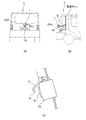
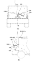
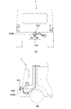
- FIG. 1A is a rear view of the vehicle (the foreign matter removing device is shown in perspective), and FIG. 1B is a side view of the rear portion of the vehicle (the foreign matter removing device is shown in perspective).
- FIG. 1C is a partially enlarged view of the rear part of the vehicle.
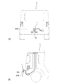
- (A), (b) in FIG. 2 is a figure which shows another example of the position where a foreign material removal apparatus is attached. It is a perspective view of a foreign substance removal device concerning a first embodiment of the present invention. It is a block diagram of the high pressure air production
- FIG. 6 is a figure for demonstrating the camera bracket with which a vehicle-mounted camera is assembled
- (A) in FIG. 11 is a rear view of the vehicle (the foreign matter removing device is shown in perspective), and (b) in FIG. 11 is a side view of the rear portion of the vehicle (the foreign matter removing device is shown in perspective). is there.
- FIG. 12 is a figure which shows another example of the position where a foreign material removal apparatus is attached. It is a block diagram of the high pressure air production
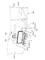
- (A), (b) in FIG. 17 is a schematic block diagram which shows the positional relationship of the nozzle with which a foreign material removal apparatus is provided, and the lens of a vehicle-mounted camera.
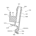
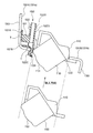
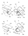
- FIGS. 18A and 18B are perspective views showing a state in which the inner member and the outer member constituting the nozzle unit are not engaged, and FIGS. 18C and 18D show the inner side. It is a perspective view which shows the state by which the member and the outer side member were engaged. It is sectional drawing which shows the example of attachment to the garnish of the nozzle unit integrated bracket which mounts the vehicle-mounted camera in a reference example.
- the foreign matter removing device of the present invention is applied as a device that removes foreign matter such as water droplets, mud and dust adhering to a lens of an in-vehicle camera.
- the foreign matter removing apparatus 1 is attached to a back door 200A of the vehicle V, for example.
- the foreign matter removing apparatus 1 includes a motor 55, and a power terminal of the motor 55 is connected to a power line of the vehicle.
- the vehicle control unit (ECU) (not shown) starts shooting by an in-vehicle camera 100 described later, and the foreign matter removing device 1 is, for example, within a few seconds at the start of shooting. It is controlled to operate by a vehicle control unit (ECU).
- the in-vehicle camera 100 is a camera for confirming, for example, the rear of the vehicle, and as shown in FIG. 1C, the lens 101 of the in-vehicle camera 100 is exposed toward the outside of the back door 200A of the vehicle. It is attached to the back door 200A.
- the in-vehicle camera 100 has an imaging unit (not shown), and the lens 101 covers the imaging unit.
- the lens includes a simple translucent cover that does not converge or diffuse light.
- the foreign material removal apparatus 1 may be attached to the rear bumper 200B of a vehicle, for example.
- the position where the in-vehicle camera 100 is attached is not limited to the rear end side of the vehicle, but may be a body panel on the front side or the side side of the vehicle.
- the meaning of “attached to the body panel” means, for example, when the in-vehicle camera is attached via a vehicle cover part such as a lamp, a door knob, a mirror, or a bumper attached to the body panel. Is included as a part of these parts (as an integral part).
- the “body panel” of the vehicle may be a panel member that constitutes the vehicle, such as a back door, a front panel that constitutes the front of the vehicle, a side panel that constitutes the side of the vehicle, a front bumper, a side bumper, a rear bumper, A cover member for design (garnish or the like) is included at least.
- the “outside of the body panel” means a direction in which the outer surface exposed to the outside of the vehicle is facing among the surfaces constituting the panel member, and the “inside of the body panel” means It means the direction in which the inner surface on the opposite side of the outer surface faces.
- the foreign matter removing apparatus 1 includes a nozzle unit 2, a camera bracket 91, a joint member 3, a hose 4, a high-pressure air generation unit 5, and an in-vehicle camera 100.
- the nozzle unit 2 is configured to be detachable from the in-vehicle camera 100, and includes an attachment portion 21 and a nozzle 22.
- the nozzle unit 2 is made of, for example, resin.
- the attachment portion 21 is attached to the housing 102 of the in-vehicle camera 100 so as to cover the upper surface of the in-vehicle camera 100.
- the nozzle 22 injects high-pressure air toward the lens 101 of the in-vehicle camera 100.
- the nozzle 22 is formed integrally with the attachment portion 21, and is provided so that the tip of the nozzle 22 faces the lens 101 when the attachment portion 21 is attached to the housing 102.
- integralally formed means that the operator can handle the nozzle 22 and the attachment portion 21 as an integral part during assembly work.
- the nozzle 22 and the attachment portion 21 may be formed with the same material and the same mold, or the nozzle 22 and the attachment portion 21 may be formed with different materials and fitted to each other.
- the nozzle unit 2 may be formed integrally.
- the other members are also defined similarly when they are described as “integrally formed”.
- the camera bracket 91 attaches the in-vehicle camera 100 to the body panel of the vehicle V. Further, the camera bracket 91 communicates the nozzle 22 and the joint member 3.
- the joint member 3 is a member that joins the camera bracket 91 and the hose 4, and has one end connected to the camera bracket 91 and the opposite end connected to the hose 4.
- the joint member 3 is made of, for example, resin.
- the hose 4 is a piping member that connects the nozzle 22 and the high-pressure air generation unit 5 together with the joint member 3. One end of the hose 4 is connected to the joint member 3, and the opposite end is connected to the discharge port 50 of the high-pressure air generation unit 5.
- the hose 4 is made of a material such as resin or rubber.
- the high-pressure air generation unit 5 is a unit for generating high-pressure air to be sent to the nozzle 22.
- the high pressure air generation unit 5 is attached to a part of the vehicle body inside the vehicle.
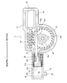
- the high-pressure air generation unit 5 includes a housing (case body) 51 and a moving mechanism (generation unit) 65 disposed inside the housing 51.
- the moving mechanism 65 generates high-pressure air.
- the moving direction of the piston 52 is the sending direction in the rear, which is the direction in which the air is sent out, and the accumulating force direction is in the direction opposite to the sending direction.
- the piston 52 In an initial state before high-pressure air is sent out, the piston 52 is positioned on the delivery direction side, and the rack 53 is positioned in a state where the rack portion 53a can mesh with the gear portion 54a of the pinion 54.
- the air (outside air) that has flowed into the front half portion (second space) 60b of the internal space 60 of the piston support portion 59 passes through the gap 61b along the step 61a. It flows through the inner space 60 toward a substantially half portion (first space) 60a on the rear side.
- the in-vehicle camera 100 is fixed to a rear bumper panel (an example of a panel member) 200 b that configures the outer surface of the rear bumper 200 ⁇ / b> B of the vehicle V, for example.
- the rear bumper panel 200b is formed with a hole 210 for mounting the in-vehicle camera 100.
- the in-vehicle camera 100 is fixed to the rear bumper panel 200b via the camera bracket 91 in a state of being fitted into the hole 210.
- a part including the lens of the in-vehicle camera 100 is arranged so as to be exposed to the outside of the rear bumper 200B, and a high-pressure air generation unit (not shown) is arranged inside the rear bumper 200B.
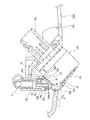
- FIG. 6A shows the in-vehicle camera 100 and the nozzle unit 2 assembled to the camera bracket 91.
- FIG. FIG. 6B shows a state where the in-vehicle camera 100 and the nozzle unit 2 are assembled to the camera bracket 91.
- FIG. 7 is a cross-sectional view taken along the line CC of FIG. 6B. In FIG. 7, a part of the rear bumper panel 200b is displayed in order to understand the positional relationship of the in-vehicle camera 100 with respect to the rear bumper panel 200b.
- the camera bracket 91 attaches the in-vehicle camera 100 to the rear bumper panel 200b with the lens 101 of the in-vehicle camera 100 exposed to the outside of the rear bumper panel 200b.
- the camera bracket 91 is provided with a conduit (an example of a through hole) 92 and an opening 95.
- the pipe line 92 is a pipe that connects the joint member 3 and the nozzle 22, has a joint side connection portion 92 ⁇ / b> A at an end portion on the side to which the joint member 3 is connected, and an end portion on the side to which the nozzle 22 is connected.
- a communication path through which high-pressure air passes is formed in the pipe line 92, a pipe-line inlet 93 through which high-pressure air flows is provided in the joint-side connection part 92A, and high-pressure air flows out to the nozzle-side connection part 92B.
- a pipeline outlet 94 is provided.
- the opening 95 is a part in which the in-vehicle camera 100 is accommodated.
- the in-vehicle camera 100 includes a connector unit 103 provided with a power supply terminal, a signal terminal, and the like.
- the connector part 103 is provided, for example, on the back part of the in-vehicle camera 100 opposite to the front part where the lens 101 of the in-vehicle camera 100 is provided.
- the in-vehicle camera 100 includes a housing 102 having a substantially cubic shape.
- the lens 101 of the in-vehicle camera 100 is provided in a state where a part is exposed from the front surface of the housing 102.
- the nozzle unit 2 is attached to the upper surface 10A of the housing 102 via an adhesive member (for example, double-sided tape) 25.
- the nozzle 22 of the nozzle unit 2 has a communication part 22A, an extending part 22B, and an ejection part 22C.
- the communication portion 22 ⁇ / b> A is a portion that communicates with the conduit outlet 94 of the conduit 92.
- the communication portion 22A is provided with an inflow port 23 through which high-pressure air flows.
- the extending portion 22B is a portion that communicates the communication portion 22A and the ejection portion 22C.
- the jet part 22C is a part from which high-pressure air is jetted, and is provided with a jet port 24 that opens horizontally (for example, rectangular, elliptical, etc.).
- the high-pressure air that has flowed into the inlet 23 of the communication part 22A is ejected from the ejection port 24 of the ejection part 22C through the communication part 22A, the extending part 22B, and the communication path formed in the ejection part 22C.
- the joint member 3 is connected to a pipe inlet 93 in the pipe 92 of the camera bracket 91.
- the joint member 3 of this example is formed integrally with the camera bracket 91.
- the joint member 3 and the camera bracket 91 may be prepared as separate parts and combined with each other during assembly.
- the vehicle-mounted camera 100 and the nozzle unit 2 having such a configuration are assembled to the camera bracket 91 in the following procedure.
- the nozzle 22 is attached to the upper surface 102 ⁇ / b> A of the camera 100 with the adhesive member 25.
- the nozzles 22 are adjusted and pasted so that the nozzles 24 of the nozzles 22 face the center point of the camera 100.
- the connector 103 of the in-vehicle camera 100 is inserted into the opening 95 of the camera bracket 91.
- the lens 101 side is rotated in the direction of the upper surface 102 ⁇ / b> A of the in-vehicle camera 100 around the inserted end of the connector unit 103, and the nozzle 22 attached to the upper surface 102 ⁇ / b> A is a conduit of the camera bracket 91. 92.
- the pipeline outlet 94 of the nozzle side coupling portion 92B of the pipeline 92 is inserted into the inlet 23 of the communicating portion 22A of the nozzle 22 so that the nozzle 22 communicates with the pipeline 92.
- the engaging portion of the camera bracket 91 is engaged with the engaging portion of the in-vehicle camera 100, and the assembly is completed.
- the nozzle unit 2 may be formed integrally with the camera bracket 91.
- the nozzle unit 2 is assembled integrally with the camera bracket 91 so as to secure an assembly path in which the in-vehicle camera 100 can be assembled into the opening 95 with respect to the opening 95 of the camera bracket 91.
- the cross-sectional area of the pipe outlet 94 of the nozzle side connecting portion 92B is smaller than the cross-sectional area of the inlet 23 of the communicating portion 22A. For this reason, in a state where the nozzle 22 is communicated with the conduit 92, gaps 96A and 96B are formed between the outer peripheral surface of the nozzle side connecting portion 92B and the inner peripheral surface of the communicating portion 22A.
- the gap 96 ⁇ / b> A communicates with the communication path 71 in the nozzle 22 through the opening 97 and the gap 96 ⁇ / b> B through the opening 98.
- the cross-sectional area d1 of the opening 97 and the cross-sectional area d2 of the opening 98 are formed smaller than the cross-sectional area of the ejection port 24 of the nozzle 22.
- the in-vehicle camera 100 assembled to the camera bracket 91 is fitted into the rear bumper panel 200b by being fitted into a hole 210 formed in the rear bumper panel 200b.
- the high-pressure air passes through the pipe line 92 from the joint member 3 and is sent to the nozzle 22 and is jetted toward the lens 101.
- the high-pressure air generated by the high-pressure air generation unit 5 can pass from the inner side to the outer side of the rear bumper panel 200b via the conduit 92 provided in the camera bracket 91. For this reason, it is not necessary to form a dedicated hole for allowing high-pressure air to pass through the rear bumper panel 200b. Therefore, the work efficiency when attaching the foreign matter removing apparatus 1 to the vehicle V is improved.
- “passing from the inside to the outside of the body panel” means that the high-pressure air moves from the space inside the panel member such as the above-described rear bumper panel to the outside space.
- the high-pressure air can pass from the high-pressure air generation unit 5 in the order of the hose 4, the joint member 3, and the pipe line 92 while maintaining the flow rate from the inside to the outside of the rear bumper panel 200b. .
- the pipe outlet 94 of the pipe 92 having a small cross-sectional area is inserted into the inlet 23 of the nozzle 22 having a large cross-sectional area. It is set as the structure which makes the nozzle 22 and the pipe line 92 communicate by inserting. According to this configuration, the assembling work when the nozzle 22 communicates with the pipe line 92 is facilitated, and the working efficiency is improved. Further, when the in-vehicle camera 100 is assembled to the camera bracket 91, the communication portion 22A of the nozzle 22 can be assembled without contacting the nozzle side coupling portion 92B of the conduit 92. Deviation can be suppressed. In addition, there is little air leakage when high-pressure air moves from the pipe 92 to the nozzle 22, and pressure loss when moving from the pipe 92 to the nozzle 22 can be reduced.
- joint member 3 is formed integrally with the camera bracket 91, the work of attaching the joint member 3 to the conduit 92 is omitted, so that the work efficiency when the foreign matter removing apparatus 1 is attached to the vehicle V is further improved. To do.
- the nozzle unit 2 integrally with the camera bracket 91, it is not necessary to prepare a dedicated bracket for attaching the nozzle unit 2 to the rear bumper panel 200b, so that the versatility of the attachment is improved and the foreign matter is improved. The work efficiency when attaching the removing device 1 to the vehicle V is further improved.
- the nozzle unit 2 can be attached with the double-sided tape 25, it is not necessary to prepare a dedicated bracket for attaching the nozzle unit 2 to the rear bumper panel 200b. The work efficiency when attaching 1 to the vehicle V is further improved.
- the foreign substance removing device 1 having the above-described configuration on the vehicle V, for example, even when the lens 101 of the in-vehicle camera 100 is contaminated with rain, mud, or the like, high pressure air is blown onto the lens. Foreign matter can be removed.
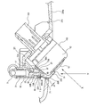
- FIG. 8 represents the state in which the camera bracket 91 with which the vehicle-mounted camera 110 was assembled
- FIG. 8B shows a through hole 192 formed in the camera bracket 91.
- the through hole 192 of the modified example is a through hole 192 through which the hose 4 passes, and a pipe line (through hole) 92 (see FIG. 6) formed to connect the nozzle 22 and the joint member 3 to each other. ) Is different.
- the through hole 192 is formed so as to penetrate the camera bracket 91, for example, in a substantially vertical direction with respect to a surface on which the camera bracket 91 is attached to the outer panel 200c.
- the hose 4 is configured to pass through a through hole 192 formed in the camera bracket 91.
- One end of the hose 4 passed through the through hole 192 is connected to the inlet 23 of the nozzle 22 disposed outside the outer panel 200c.
- the opposite end of the hose 4 is connected to a discharge port 50 of a high-pressure air generation unit (not shown) 5 disposed inside the outer panel 200c.
- the nozzle 22 is attached to the in-vehicle camera 100.
- a garnish 201 is provided so as to cover the in-vehicle camera 100 and the like arranged so as to protrude outside the outer panel 200c.
- the hose 4 passes from the inner side of the outer panel 200c to the outer side through the through hole 192 of the camera bracket 91, and the high-pressure air generated inside the outer panel 200c is moved to the outer side of the outer panel 200c. It is possible to easily realize a configuration that allows passage. For this reason, the work efficiency at the time of attaching the foreign material removal apparatus 1 to the vehicle V improves.
- the nozzle unit 2 may be formed integrally with the camera bracket 91.
- the nozzle unit 2 is assembled integrally with the camera bracket 91 so as to secure an assembly path in which the in-vehicle camera 100 can be assembled in the opening 95 with respect to the opening 95 of the camera bracket 91. Also good.
- the cross-sectional area of the pipe outlet 94 of the nozzle side connecting portion 92B is smaller than the cross-sectional area of the inflow port 23 of the communicating portion 22A.
- the gap 96A is formed in the same manner through an opening 97 formed between the tip end portion (wall of the conduit outlet 94) of the nozzle side connecting portion 92B and the back side of the communication portion 22A.
- the communication path 71 in the nozzle 22 is communicated with each other through the opening 98.
- a part of the communication path 71 on the side close to the ejection port 24 is formed by the wall of the nozzle 22 (extension part 22 ⁇ / b> B, ejection part 22 ⁇ / b> C), the shoulder on the front surface of the housing 102, and the like.
- the cross-sectional area d1 of the opening 97 and the cross-sectional area d2 of the opening 98 are formed smaller than the cross-sectional area of the ejection port 24 of the nozzle 22.
- a cover part (an example of a rib) 99 is formed at the distal end of the pipe line 92.
- the cover part 99 constitutes a part of the nozzle side connecting part 92B and is formed on the outer peripheral side of the pipe outlet 94.
- the cover part 99 is disposed outside the communication part 22A of the nozzle 22 so as to cover the communication part 22A while leaving a gap as large as the gap 96B.
- the gap 96 ⁇ / b> B communicates with a gap formed by the cover portion 99, and communicates with the outside of the nozzle 22 through an opening 118 formed between the distal end portion of the cover portion 99 and the communicating portion 22 ⁇ / b> A of the nozzle 22.
- the gap 96A communicates with the outside of the nozzle 22 through an opening 117 formed between the inner side of the nozzle side coupling portion 92B and the tip end portion (wall of the inflow port 23) of the communication portion 22A.
- the in-vehicle camera 100 assembled to the camera bracket 91 is fitted into the rear bumper panel 200b by being fitted into a hole 210 formed in the rear bumper panel 200b.
- the high-pressure air passes through the pipe line 92 from the joint member 3 and is sent to the nozzle 22 and is jetted toward the lens 101.
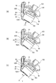
- the in-vehicle camera 100 having such a configuration is assembled to the camera bracket 91 according to the procedure shown in FIGS.
- the nozzle 22 is attached to the upper surface 102 ⁇ / b> A of the camera 100 by the adhesive member 25.
- the nozzles 22 are adjusted and pasted so that the nozzles 24 of the nozzle 22 face the center point of the camera 100.
- the in-vehicle camera 100 is inserted into the camera bracket 91 (in the direction of the arrow X) through the opening 95 of the camera bracket 91.
- the connector portion 103 of the in-vehicle camera 100 is inserted into the opening 120 formed in the back wall of the camera bracket 91.
- the direction of the arrow X is an attachment direction when the in-vehicle camera 100 is attached to the rear bumper panel 200b.
- the lens 101 side of the in-vehicle camera 100 is directed toward the upper surface 102 ⁇ / b> A of the in-vehicle camera 100 with the front end side of the inserted connector portion 103 as the center. It is rotated. Thereby, the nozzle 22 affixed to the upper surface 102 ⁇ / b> A of the housing 102 is brought close to the conduit 92 of the camera bracket 91.
- the direction of the arrow Y is the communication direction when the nozzle 22 and the pipe line 92 communicate with each other.
- the attachment direction X and the communication direction Y intersect each other (see (c) in FIG. 10).
- the nozzle side connection portion 92 ⁇ / b> B of the conduit 92 is inserted into the inlet 23 of the communication portion 22 ⁇ / b> A of the nozzle 22.
- the nozzle 22 communicates with the pipe line 92.
- the nozzle unit 2 is attached to the housing 102 of the in-vehicle camera 100, when the in-vehicle camera 100 is attached to the rear bumper panel 200b of the vehicle V, the nozzle 22 and the conduit 92 of the nozzle unit 2 are Will communicate. Since the inlet 23 of the nozzle 22 is larger than the pipe outlet 94 of the pipe 92, when the nozzle side connecting portion 92 ⁇ / b> B of the pipe 92 is inserted into the inlet 23 of the nozzle 22, Is difficult to touch.
- the high-pressure air generated by the high-pressure air generation unit 5 can pass from the inside to the outside of the rear bumper panel 200b through a pipe line 92 provided in the camera bracket 91. For this reason, it is not necessary to form a dedicated hole for allowing high-pressure air to pass through the rear bumper panel 200b. Therefore, the work efficiency when attaching the foreign matter removing apparatus 1 to the vehicle V is improved.
- “passing from the inside to the outside of the body panel” means that the high-pressure air moves from the space inside the panel member such as the above-described rear bumper panel to the outside space.
- the inlet 23 of the nozzle 22 is formed larger than the pipe outlet 94 of the pipe 92, the nozzle 22 and the pipe 92 are unlikely to come into contact with each other.
- the work efficiency can be improved.
- the gaps 96A and 96B between the outer peripheral surface of the pipe 92 and the inner peripheral surface of the nozzle 22 can function as a bypass path. Then, intake for generating high-pressure air can be performed using the gaps 96A and 96B.
- cover portion 99 is formed at the tip of the pipe line 92, it is difficult for water to enter the gap 96B, and it is easy to maintain the performance of removing foreign matter even in rainy weather.
- the in-vehicle camera 100 is attached to the camera bracket 91 in advance, the efficiency of the work of attaching the in-vehicle camera 100 to the rear bumper panel 200b is improved.
- the foreign substance removing device 1 having the above-described configuration on the vehicle V, for example, even when the lens 101 of the in-vehicle camera 100 is contaminated with rain, mud, or the like, high pressure air is blown onto the lens. Foreign matter can be removed.
- the foreign matter removing device 1001 is attached to a back door 1200A of the vehicle V, for example.
- the foreign matter removing apparatus 1001 includes a drive unit 1055, and a power supply terminal of the drive unit 1055 is connected to a power supply line of the vehicle V.
- the vehicle control unit ECU
- the vehicle control unit starts shooting with an in-vehicle camera 1100, which will be described later. It is controlled to operate by a vehicle control unit (ECU).
- the foreign matter removing apparatus 1001 includes a nozzle unit 1002, a hose 1004, and a high-pressure air generation unit (an example of a generation unit) 1005.
- the hose 1004 is a piping member that connects the nozzle unit 1002 and the high-pressure air generation unit 1005.
- the high-pressure air generation unit 1005 is a unit for generating high-pressure air that is sent to the nozzle 1022.
- the high-pressure air generation unit 1005 is attached to a part of the vehicle body inside the vehicle V.
- the foreign matter removing device 1001 may be attached to, for example, a rear bumper 1200B of the vehicle V as shown in FIGS. 12 (a) and 12 (b).
- the high-pressure air generation unit 1005 includes a case body 1051 and a moving mechanism disposed inside the case body 1051.
- the moving direction of the piston 1052 is the rear direction, which is the direction in which air is sent out, and the forward direction, which is the direction opposite to the sending direction, is the reservoir force direction.
- the piston 1052 In an initial state before high-pressure air is sent out, the piston 1052 is positioned on the delivery direction side, and the rack 1053 is positioned in a state where the rack portion 1053a can be engaged with the gear portion 1054a of the pinion 1054.
- the air (outside air) that has flowed into the front half of the internal space 1060 (second space) 1060b of the piston support portion 1059 passes through the gap 1061b along the step 1061a. It flows through the inner space 1060 toward a substantially half portion (first space) 1060a on the rear side.
- the gear portion 1054a and the rack portion 1053a are disengaged, and the piston 1052 moves in the delivery direction at a higher speed than the moving speed in the direction of the reserve force by the biasing force of the biasing spring 1058. Is done.
- the air that has flowed from the second space 1060b to the first space 1060a passes from the first space 1060a to the nozzle 1022 of the nozzle unit 1002 through the hose 1004 through the discharge port 1050 of the connecting projection 1062. Sent out.
- the diameter of the discharge port 1050 is smaller than the diameter of the piston support part 1059, the air discharged from the first space 1060a through the discharge port 1050 is compressed and sent as high-pressure air. Is done.
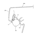
- the in-vehicle camera 1100 is a camera for confirming, for example, the rear side of the vehicle. As shown in FIG. 14, the in-vehicle camera 1100 is mounted on a garnish 1300 (an example of a vehicle body panel) provided outside the body panel 1210 constituting the back door 1200A. It is attached via an attachment member 1110. Accordingly, the lens 1101 of the in-vehicle camera 1100 is disposed so as to be exposed toward the outside of the garnish 1300.
- the in-vehicle camera 1100 has an imaging unit (not shown), and the lens 1101 covers the imaging unit.
- the lens 1101 includes a simple translucent cover that does not converge or diffuse light.
- the position where the in-vehicle camera 1100 is attached is not limited to the rear end side of the vehicle, and may be a body panel on the front side or the side side of the vehicle. Further, the in-vehicle camera 1100 may be attached to the vehicle body via vehicle cover parts such as a lamp, a door knob, a mirror, and a bumper attached to the body panel. As well).
- the nozzle unit 1002 is attached to the inner surface (surfaces 1301A and 1301B facing the body panel 1210) of the garnish 1300, and includes an attachment portion 1021 and a nozzle 1022.
- 1002 is formed of, for example, a resin.
- the garnish 1300 has a first surface 1301a (see FIG. 16) having an inner side surface 1301A extending in a direction substantially along the vertical direction of the vehicle, and a second surface 1301b (see FIG. 16) having an inner side surface 1301B is in the horizontal direction of the vehicle. It is formed in a substantially L shape extending in a direction substantially along the line.
- the attachment portion 1021 has a first attachment portion 1021A and a second attachment portion 1021B.
- the first mounting portion 1021A includes a first adhesive surface 1021A1 that protrudes laterally from the nozzle 1022 and is adhered to the first surface 1301a (inner side surface 1301A) of the garnish 1300 by an adhesive tape T.
- the second attachment portion 1021B includes a second adhesive surface 1021B1 that protrudes downward from the first attachment portion 1021A and is adhered to the second surface 1301b (inner side surface 1301B) of the garnish 1300 by the adhesive tape T.
- the first attachment portion 1021A and the second attachment portion 1021B can employ adhesive bonding, engagement by screwing, or the like in addition to the bonding method using the adhesive tape T such as a double-sided tape.
- the nozzle 1022 injects high-pressure air toward the lens 1101 of the in-vehicle camera 1100.
- the nozzle 1022 is formed integrally with the attachment portion 1021, and is provided so that the tip of the nozzle 1022 faces the lens 1101 when the attachment portion 1021 is attached to the garnish 1300.
- integrally formed means that the operator can handle the nozzle 1022 and the mounting portion 1021 as an integral part during assembly work.
- the nozzle 1022 and the mounting portion 1021 may be molded from the same material and using the same mold, or the nozzle 1022 and the mounting portion 1021 may be molded from different materials and fitted together.
- the nozzle unit 1002 may be formed integrally.
- the nozzle 1022 has a connecting portion 1022A, an extending portion 1022B, and an ejection portion 1022C.
- the connecting portion 1022A is a portion to which the hose 1004 is connected.
- the connection portion 1022A is provided with an inflow port 1023 into which high-pressure air flows.
- the extending portion 1022B is a portion that connects the connecting portion 1022A and the ejection portion 1022C.
- the ejection part 1022C is a part from which high-pressure air is ejected.
- the ejection portion 1022C has a shape that is bent toward the side opposite to the lens 1101 and then bent toward the lens 1101 and opened. That is, the ejection part 1022C is formed in a substantially S shape, and the ejection port 1024 provided at the tip thereof is arranged toward the front surface of the lens 1101 as shown in FIG.
- the high-pressure air that has flowed into the inflow port 1023 of the connection part 1022A is ejected from the ejection port 1024 of the ejection part 1022C through the communication path formed in the extending part 1022B.
- a certain gap S is formed between the garnish 1300 and the in-vehicle camera 1100 and the camera mounting member 1110 attached to the garnish 1300.
- the ejection portion 1022C of the nozzle 1022 protrudes from the opening 1302 of the garnish 1300 to the outside of the vehicle via the gap S.
- the nozzle unit 1002 is configured to be detachable from the in-vehicle camera 1100.
- the line C passing through the center of the injection port 1024 of the nozzle 1022 and the lens When the angle formed by the tangent L of the vertex of 1101 is ⁇ , the nozzle 1022 is positioned with respect to the lens 1101 so that the angle ⁇ is not less than 0 ° and not more than 60 °.
- the angle ⁇ is preferably 5 ° or more and 30 ° or less.
- the injection port 1024 of the nozzle 1022 As described above, by arranging the injection port 1024 of the nozzle 1022 with a predetermined inclination with respect to the lens 1101, it becomes easy to blow high-pressure air over the entire surface of the lens 1101, and the performance of removing water droplets is improved. Can do.
- the lens mounted on the in-vehicle camera is not a curved lens 1101 as in the present embodiment but a flat lens (for example, a plano-concave lens), the line along the surface of the flat lens is The nozzle 1022 may be positioned with respect to the planar lens so that the angle ⁇ formed between the lens plane and the center line C of the nozzle 1024 of the nozzle 1022 is 0 ° or more and 60 ° or less.
- the lens 1101 is divided into six equal parts in the vertical direction, and from the top, the first area 1101A, the second area 1101B, the third area 1101C, the fourth area 1101D, and the fifth area 1101E.
- center line C of nozzle 1024 of nozzle 1022 intersects the 2nd field 1101B second from the top of lens 1101. In this way, by positioning the injection port 1024 of the nozzle 1022 toward a certain region (second region 1101B) on the upper side of the lens 1101, it becomes easy to blow high-pressure air over the entire surface of the lens 1101, and the performance of water droplet removal is improved. Can be improved.
- the ejection part 1022C is composed of an inner member 1025, an outer member 1026, and a connecting part 1027.
- the inner member 1025 constitutes one wall portion facing the lens 1101 in a state where the nozzle unit 1002 is attached to the garnish 1300.
- the inner member 1025 has a protrusion 1025a that protrudes toward the outer member 1026 side.
- the outer member 1026 is disposed on the opposite side of the lens 1101 with the inner member 1025 interposed therebetween, and constitutes the other wall portion extending directly from the extending portion 1022B of the nozzle 1022.
- the outer member 1026 has a groove 1026a for receiving the protrusion 1025a of the inner member 1025.
- the connecting portion 1027 is a member that connects the inner member 1025 and the outer member 1026, and includes two pairs of small diameter wire portions.
- the outer shape of the inner member 1025 is a shape corresponding to the outer shape of the groove portion 1026a of the outer member 1026, and the inner member 1025 is bent by bending the connecting portion 1027 as shown in FIGS. 1025 is accommodated in the outer member 1026 (the inner member 1025 and the outer member 1026 are combined) to form a hollow ejection portion 1022C.
- the high-pressure air flows into the inlet 1023 of the nozzle 1022 and is ejected from the ejection port 1024 through the communication path.
- High-pressure air ejected from the ejection port 1024 is blown toward the lens 1101 of the in-vehicle camera 1100.
- foreign matters such as water droplets, dust, and mud attached to the lens 1101 are blown off, and the dirt on the lens 1101 is eliminated.
- the bracket 1110A including the nozzle unit 1002A interferes with the size of the opening 1302 of the garnish 1300. Therefore, the bracket 1110A with the nozzle unit 1002A on which the in-vehicle camera 1100 is mounted cannot be inserted from the opening 1302 of the garnish 1300 and attached to the garnish 1300.
- the nozzle unit 1002 is attached to the inner side surface of the garnish 1300, and the ejection portion, garnish, which is the tip of the nozzle 1022. 1300 and the camera mounting member 1110 for mounting the in-vehicle camera 1100 or the in-vehicle camera 1100 to the garnish 1300, and protrudes outside the vehicle toward the front surface of the lens 1101 of the in-vehicle camera 1100. Has been placed.
- the nozzle unit 1002 is attached to the inner side surfaces 1301A and 1302B (first surface 1301a and second surface 1302b) of the garnish 1300 with the garnish 1300 attached to the body panel 1210. Then, the camera attachment member 1110 to which the camera 1100 is attached can be inserted from the opening 1302 of the garnish 1300 and attached to the body panel 1210. In this manner, the ejection portion 1022C can be disposed without interfering with the in-vehicle camera 1100 and the camera attachment member 1110 attached to the garnish 1300.
- the garnish 1300 there is no need for post-processing to the garnish 1300 such as removing the garnish 1300 from the body panel 1210 to attach the camera 1100 or the nozzle unit 1002 or enlarging or deforming the opening 1302 of the garnish 1300, and removing foreign matter.
- the versatility and work efficiency when the apparatus 1001 is attached to the vehicle are improved.
- the garnish 1300 itself does not need to ensure water tightness, the in-vehicle camera 1100 and the nozzle unit 1002 can be attached to the garnish 1300 without providing a seal member or the like in the opening 1302 of the garnish 1300.
- the ejection portion 1022C of the nozzle 1022 has a shape that is bent toward the side opposite to the lens 1101 and then bent toward the lens 1101 side to be opened. In this manner, the ejection portion 1022C is formed in a substantially S-shape by being bent, and even when the gap S between the garnish 1300 and the camera mounting member 1110 is narrow, the ejection portion 1022C is ejected toward the lens 1101 of the camera 1100. The optimal position of the jet port 1024 of the part 1022C can be ensured, and the performance of removing foreign matter can be maintained.
- the ejection portion 1022C includes an inner member 1025 facing the lens 1101 and an outer member 1026 disposed on the opposite side of the lens 1101 with the inner member 1025 interposed therebetween, and the inner member 1025 and the outer member 1026 are coupled.
- a hollow ejection portion 1022C is formed.
- the jet part 1022C is formed by dividing the inner member 1025 and the outer member 1026 into parts, and these are combined and assembled, thereby improving the design freedom of the shape of the jet part 1022C and the gold Costs related to mold production can be reduced.
- the ejection part 1022C further includes a connecting part 1027 that connects the inner member 1025 and the outer member 1026, and the inner member 1025 and the outer member 1026 are coupled by bending the connecting part 1027. For this reason, the operation
- the in-vehicle camera 1100 is attached to the garnish 1300 via the camera attachment member 1110.
- the in-vehicle camera 1100 may be attached to the body panel 1210 of the vehicle.
- the in-vehicle camera 1100 can be inserted from the opening 1302 of the garnish 1300 and attached to the body panel 1210 with a dedicated bracket, and the garnish 1300 can be removed. There is no need to enlarge the size of the opening 1302.
- the nozzle unit and the in-vehicle camera are directly attached to the body panel (an example of the vehicle body panel), and the opening of the body panel and the in-vehicle camera It is good also as a structure from which the ejection part of a nozzle protrudes from the clearance gap between these. In this case, in order to ensure the water tightness of the body panel, it is desirable to provide a seal member or the like at the opening of the body panel.
- the nozzle unit 1002 includes a first mounting portion 1021A that protrudes laterally from the nozzle 1022 in accordance with the shape of the garnish 1300 formed in a substantially L shape, and the first mounting portion 1021A. Although it has the attachment part 1021 provided with the 2nd attachment part 1021B which protrudes below, it is not restricted to this example. Since the nozzle unit 1002 is a member independent of the camera mounting member 1110 of the in-vehicle camera 1100, the shape of the mounting portion 1021 of the nozzle unit 1002 can be appropriately changed according to the shape of the vehicle body panel or garnish. .
- the hose 1004 is directly connected to the nozzle 1022 of the nozzle unit 1002 so that high-pressure air flows from the high-pressure air generation unit 1005.
- the nozzle 1022 and the hose 1004 for example, You may connect a substantially L-shaped joint member.
- this invention is not limited to embodiment mentioned above, A deformation
- the material, shape, dimension, numerical value, form, number, location, and the like of each component in the above-described embodiment are arbitrary and are not limited as long as the present invention can be achieved.
- the application to the vehicle-mounted camera is described, but the target to which the present invention is applied is not limited as long as it is a camera used outdoors.
- the target to which the present invention is applied is not limited as long as it is a camera used outdoors.
- it includes a camera attached so as to be exposed to the outside such as an aircraft, a railway, a ship, a robot, an outdoor installation, a building, and the like.
- the present invention is applicable to sensors that can be attached to a vehicle, such as LIDAE (laser radar), millimeter wave radar, and ultrasonic sensor.
- LIDAE laser radar
- millimeter wave radar millimeter wave radar
- ultrasonic sensor ultrasonic sensor
- the target part from which the foreign substance removing device removes the foreign substance is not limited to the camera lens.
- an optical lens of a sensor element a cover that covers the front surface of the optical lens, a lamp that has a part that functions as a communication window for the sensor, a cover for vehicle cover parts such as a mirror, a bumper, a grille, and a doorknob, and a sensor mounted in the vehicle compartment
- the present invention can be applied to a foreign matter removing apparatus that removes foreign matter adhering to a “partition wall” defined as a concept encompassing a vehicle window and the like in such a case.
- This partition is not limited to a transparent member (translucent), and may not be transparent in an ultrasonic sensor, a millimeter wave radar, or the like.
Landscapes
- Engineering & Computer Science (AREA)
- Mechanical Engineering (AREA)
- Multimedia (AREA)
- Signal Processing (AREA)
- Studio Devices (AREA)
- Closed-Circuit Television Systems (AREA)
Abstract
本発明の異物除去装置は、車載カメラ(100)が有するレンズ(101)に付着した異物を除去するための異物除去装置であって、レンズ(101)が車両のリアバンパーパネル(200b)の外側に向けて露出した状態で、車載カメラ(100)を車両のリアバンパーパネル(200b)に取り付けるためのカメラブラケット(91)と、リアバンパーパネル(200b)の内側に配置されるとともに、高圧空気を生成する高圧空気生成ユニットと、高圧空気をレンズ(101)に向けて噴射するノズル(22)を有するノズルユニットとを備え、カメラブラケット(91)には、管路(92)が形成され、高圧空気生成ユニットが生成した高圧空気は、管路(92)を介してリアバンパーパネル(200b)の内側から外側に通過するとともに、ノズル(22)からレンズ(101)に向けて噴射される。
Description
本発明は、高圧空気を噴射して異物を除去する装置に関するものである。
近年、車両周囲の状況を撮影する車載カメラが搭載された車両が増えてきている。車載カメラは、撮像面であるレンズが雨や泥等で汚れてしまう場合がある。このため、従来、レンズ上に付着した水滴等の異物を除去するために、車載カメラのレンズに洗浄液や高圧空気等を吹き付けて異物を除去する異物除去装置が知られている。
このような異物除去装置では、カメラのレンズに対するノズルの先端の位置決め精度が低いと、異物を除去する性能が低下してしまう場合がある。そこで、例えば、車両のボディパネルに専用のブラケットを設けて、その専用のブラケットを介してノズルがレンズに対して位置決めされる構成が提案されている(特許文献1参照)。特許文献1では、カメラの一部およびノズルは、ボディパネルの後部に設けられたガーニッシュとボディパネルとの間の空間に配置され、カメラの撮像面は、ガーニッシュの開口部から外部へ突出している。
また、下記の特許文献1の異物除去装置では、洗浄液が収容されるタンクと洗浄液を噴射するためのユニットが車両のボディパネルの内側に搭載される。そして、車両のボディパネルに専用のノズルブラケットが取り付けられ、そのノズルブラケットを介して、車両の外側に向けて露出するレンズ上に洗浄液が噴射される(特許文献1参照)。
特許文献1の構成では、異物除去装置を車両に取り付ける作業時に、車両のボディパネルに、車載カメラを嵌めるための孔の他に、ノズルブラケットを嵌めるための孔を形成しなければならない。このため、異物除去装置を取り付ける際の作業効率が低下してしまう。
本発明の目的の一つは、異物除去装置を車両等の対象物に取り付ける際の作業効率を向上させることが可能な異物除去装置および当該異物除去装置を備える車両を提供することである。
また、特許文献1の構成では、組立作業者は、挿入口を有するカメラブラケットに対して車載カメラを挿入する際、車載カメラのハウジング等がノズルの先端に接触しないように作業を行わなければならず、作業効率が低くなってしまう。車載カメラのハウジング等がノズルの先端に接触してしまうと、車載カメラのレンズに対するノズルの位置決めにズレが生じてしまい、異物を除去する性能を低下してしまう。
また、車両のボディパネルの形状は車両の種類によって様々である。このため、車体に対して、車載カメラを取り付ける方向と、高圧空気を通す管路(ノズルブラケットやジョイント部材等)を取り付ける方向とは、一致しない場合が多いと考えられる。高圧空気を噴射するノズルは車載カメラに対して近接した位置に取り付けられるため、車載カメラと管路の取りつけ方向が異なると、それぞれの取り付け作業時に必要なスペースが互いに干渉してしまうことがある。この場合も、異物除去装置を車両に取り付ける際の作業効率が低下してしまう。
また、車両のボディパネルの形状は車両の種類によって様々である。このため、車体に対して、車載カメラを取り付ける方向と、高圧空気を通す管路(ノズルブラケットやジョイント部材等)を取り付ける方向とは、一致しない場合が多いと考えられる。高圧空気を噴射するノズルは車載カメラに対して近接した位置に取り付けられるため、車載カメラと管路の取りつけ方向が異なると、それぞれの取り付け作業時に必要なスペースが互いに干渉してしまうことがある。この場合も、異物除去装置を車両に取り付ける際の作業効率が低下してしまう。
本発明の目的の一つは、異物を除去する性能を維持しつつ、異物除去装置を車両等の対象物に取り付ける際の作業効率を向上させることが可能な異物除去装置および当該異物除去装置を備える車両を提供することである。
また、一般に、ガーニッシュとボディパネルとの間の空間やガーニッシュの開口部の大きさには制約がある。このため、特許文献1のように専用のブラケットにノズルを組み付ける方法では、ガーニッシュをボディパネルに取り付けたままカメラやノズルをボディパネルに組み付けることはできず、ボディパネルからガーニッシュを取り外してカメラ及びノズルをボディパネルに組み付けた後に再びガーニッシュをボディパネルに取付なければならず、異物除去装置を車両に取り付ける際の汎用性や作業効率が低下してしまう。
本発明の目的の一つは、異物を除去する性能を維持しつつ、車両等の対象物に取り付ける際の汎用性や作業効率を向上させることが可能な異物除去装置および当該異物除去装置を備える車両を提供することである。
上記目的を達成するために、本発明の異物除去装置は、
車載カメラが有するレンズに付着した異物を除去するための異物除去装置であって、
前記レンズが車両のボディパネルの外側に向けて露出した状態で、前記車載カメラを車両のボディパネルに取り付けるためのカメラブラケットと、
前記ボディパネルの内側に配置されるとともに、高圧空気を生成する高圧空気生成ユニットと、
前記高圧空気を前記レンズに向けて噴射するノズルを有するノズルユニットと、を備え、
前記カメラブラケットには、貫通孔が形成され、
前記高圧空気生成ユニットが生成した前記高圧空気は、前記貫通孔を介して前記ボディパネルの内側から外側に通過するとともに、前記ノズルから前記レンズに向けて噴射される。
車載カメラが有するレンズに付着した異物を除去するための異物除去装置であって、
前記レンズが車両のボディパネルの外側に向けて露出した状態で、前記車載カメラを車両のボディパネルに取り付けるためのカメラブラケットと、
前記ボディパネルの内側に配置されるとともに、高圧空気を生成する高圧空気生成ユニットと、
前記高圧空気を前記レンズに向けて噴射するノズルを有するノズルユニットと、を備え、
前記カメラブラケットには、貫通孔が形成され、
前記高圧空気生成ユニットが生成した前記高圧空気は、前記貫通孔を介して前記ボディパネルの内側から外側に通過するとともに、前記ノズルから前記レンズに向けて噴射される。
この構成によれば、高圧空気生成ユニットが生成する高圧空気は、カメラブラケットに形成された貫通孔を介して、車両のボディパネルの内側から外側まで通過することが可能である。このため、車両のボディパネルに、高圧空気を通過させるための孔を形成する必要が無い。このため、異物除去装置を車両に取り付ける際の作業効率が向上する。
また、本発明の異物除去装置において、
前記貫通孔は、前記高圧空気が通過する管路であっても良い。
前記貫通孔は、前記高圧空気が通過する管路であっても良い。
この構成によれば、高圧空気は、カメラブラケットに形成された管路を介して、車両のボディパネルの内側から外側まで通過することが可能である。
また、本発明の異物除去装置において、
前記高圧空気生成ユニットは、前記高圧空気を排出する排出口を有し、
前記管路は、前記高圧空気が流入する管路入口と、前記高圧空気が流出する管路出口と、を有し、
さらに、
前記排出口と前記管路入口とを接続するホースと、
前記ホースと前記管路入口とを連結するジョイント部材と、
を備えても良い。
前記高圧空気生成ユニットは、前記高圧空気を排出する排出口を有し、
前記管路は、前記高圧空気が流入する管路入口と、前記高圧空気が流出する管路出口と、を有し、
さらに、
前記排出口と前記管路入口とを接続するホースと、
前記ホースと前記管路入口とを連結するジョイント部材と、
を備えても良い。
この構成によれば、高圧空気は、高圧空気生成ユニットから、ホース、ジョイント部材および管路の順で通過し、車両のボディパネルの内側から外側まで流速を維持しながら通過することが可能である。
また、本発明の異物除去装置において、
前記ノズルは、前記高圧空気が流入する流入口を有し、
前記流入口は前記管路出口より大きく、
前記ノズルが前記管路に連通された状態において、前記管路の外周面と前記流入口の内周面との間には隙間が形成されていても良い。
前記ノズルは、前記高圧空気が流入する流入口を有し、
前記流入口は前記管路出口より大きく、
前記ノズルが前記管路に連通された状態において、前記管路の外周面と前記流入口の内周面との間には隙間が形成されていても良い。
この構成によれば、ノズルを管路に連通させる際の組み立て作業が容易となる。
また、本発明の異物除去装置において、
前記ジョイント部材は、前記カメラブラケットと一体的に形成されていても良い。
前記ジョイント部材は、前記カメラブラケットと一体的に形成されていても良い。
この構成によれば、ジョイント部材を管路に取り付ける作業が省略されるため、異物除去装置を車両に取り付ける際の作業効率がさらに向上する。
また、本発明の異物除去装置において、
前記ノズルユニットは、前記カメラブラケットと一体的に形成されていても良い。
前記ノズルユニットは、前記カメラブラケットと一体的に形成されていても良い。
この構成によれば、ノズルユニットを車両のボディパネルに取り付けるための専用ブラケットを準備する必要がなくなり、取り付けの汎用性が向上とするとともに、異物除去装置を車両に取り付ける際の作業効率がさらに向上する。
また、本発明の異物除去装置において、
前記ノズルユニットは、前記車載カメラのハウジングに接着部材を介して取り付けられても良い。
前記ノズルユニットは、前記車載カメラのハウジングに接着部材を介して取り付けられても良い。
この構成によれば、ノズルユニットを車両のボディパネルに取り付けるための専用ブラケットを準備する必要がなくなり、取り付けの汎用性が向上とするとともに、異物除去装置を車両に取り付ける際の作業効率がさらに向上する。
また、本発明の異物除去装置において、
前記高圧空気生成ユニットは、前記高圧空気を排出する排出口を有し、
前記ノズルは、前記高圧空気が流入する流入口を有し、
前記排出口と前記流入口とを接続するホースを、備え、
前記ホースは、前記貫通孔を通過していても良い。
前記高圧空気生成ユニットは、前記高圧空気を排出する排出口を有し、
前記ノズルは、前記高圧空気が流入する流入口を有し、
前記排出口と前記流入口とを接続するホースを、備え、
前記ホースは、前記貫通孔を通過していても良い。
この構成によれば、ホースがカメラブラケットの貫通孔を介してボディパネルの内側から外側へ通過しており、高圧空気をボディパネルの外側に通過させる構成を簡易に実現できる。
また、本発明の異物除去装置は、
カメラのレンズに付着した異物を除去するための異物除去装置であって、
前記レンズがパネル部材の外側に向けて露出した状態で、前記カメラを前記パネル部材に取り付けるためのカメラブラケットと、
前記パネル部材の内側に配置されるとともに、高圧空気を生成する高圧空気生成ユニットと、
前記高圧空気を前記レンズに向けて噴射するノズルを有するノズルユニットと、を備え、
前記カメラブラケットには、貫通孔が形成され、
前記高圧空気生成ユニットが生成した前記高圧空気は、前記貫通孔を介して前記パネル部材の内側から外側に通過するとともに、前記ノズルから前記レンズに向けて噴射される。
カメラのレンズに付着した異物を除去するための異物除去装置であって、
前記レンズがパネル部材の外側に向けて露出した状態で、前記カメラを前記パネル部材に取り付けるためのカメラブラケットと、
前記パネル部材の内側に配置されるとともに、高圧空気を生成する高圧空気生成ユニットと、
前記高圧空気を前記レンズに向けて噴射するノズルを有するノズルユニットと、を備え、
前記カメラブラケットには、貫通孔が形成され、
前記高圧空気生成ユニットが生成した前記高圧空気は、前記貫通孔を介して前記パネル部材の内側から外側に通過するとともに、前記ノズルから前記レンズに向けて噴射される。
この構成によれば、高圧空気生成ユニットが生成する高圧空気は、カメラブラケットに形成された貫通孔を介して、パネル部材の内側から外側まで通過することが可能である。このため、パネル部材に、高圧空気を通過させるための孔を形成する必要が無い。このため、異物除去装置を車両に取り付ける際の作業効率が向上する。
また、本発明の異物除去装置は、
車載センサーと当該車載センサーの測定対象との間に介在する隔壁に付着する異物を除去するための異物除去装置であって、
前記隔壁がパネル部材の外側に向けて露出した状態で、前記車載センサーを前記パネル部材に取り付けるためのブラケットと、
前記パネル部材の内側に配置されるとともに、高圧空気を生成する高圧空気生成ユニットと、
前記高圧空気を前記隔壁に向けて噴射するノズルを有するノズルユニットと、を備え、
前記ブラケットには、貫通孔が形成され、
前記高圧空気生成ユニットが生成した前記高圧空気は、前記貫通孔を介して前記パネル部材の内側から外側に通過するとともに、前記ノズルから前記隔壁に向けて噴射される。
車載センサーと当該車載センサーの測定対象との間に介在する隔壁に付着する異物を除去するための異物除去装置であって、
前記隔壁がパネル部材の外側に向けて露出した状態で、前記車載センサーを前記パネル部材に取り付けるためのブラケットと、
前記パネル部材の内側に配置されるとともに、高圧空気を生成する高圧空気生成ユニットと、
前記高圧空気を前記隔壁に向けて噴射するノズルを有するノズルユニットと、を備え、
前記ブラケットには、貫通孔が形成され、
前記高圧空気生成ユニットが生成した前記高圧空気は、前記貫通孔を介して前記パネル部材の内側から外側に通過するとともに、前記ノズルから前記隔壁に向けて噴射される。
また、本発明の車両は、上述の異物除去装置を備えている。
この構成によれば、例えば、車載カメラのレンズが雨や泥等で汚れてしまった場合であっても、高圧空気を吹き付けてレンズ上の異物を除去することができる。
また、上記目的を達成するために、本発明の異物除去装置は、
車載カメラのレンズが車両のボディパネルの外側に向けて露出した状態となるように車両に取り付けられた当該車載カメラのレンズ上の異物に付着する異物を除去するための異物除去装置であって、
前記ボディパネルの内側に配置されるとともに、高圧空気を生成する高圧空気生成ユニットと、
前記高圧空気を前記レンズに向けて噴射するノズルを有するとともに、前記車載カメラのハウジングに取り付けられたノズルユニットと、
前記高圧空気生成ユニットが生成した前記高圧空気を、前記ボディパネルの内側から外側に通過させるための管路と、
を備え、
前記管路は、前記高圧空気が流入する管路入口と、前記高圧空気が流出する管路出口と、を有し、
前記ノズルは、前記高圧空気が流入する流入口を有し、
前記流入口は前記管路出口より大きく、
前記管路出口が前記流入口に挿入されている。
車載カメラのレンズが車両のボディパネルの外側に向けて露出した状態となるように車両に取り付けられた当該車載カメラのレンズ上の異物に付着する異物を除去するための異物除去装置であって、
前記ボディパネルの内側に配置されるとともに、高圧空気を生成する高圧空気生成ユニットと、
前記高圧空気を前記レンズに向けて噴射するノズルを有するとともに、前記車載カメラのハウジングに取り付けられたノズルユニットと、
前記高圧空気生成ユニットが生成した前記高圧空気を、前記ボディパネルの内側から外側に通過させるための管路と、
を備え、
前記管路は、前記高圧空気が流入する管路入口と、前記高圧空気が流出する管路出口と、を有し、
前記ノズルは、前記高圧空気が流入する流入口を有し、
前記流入口は前記管路出口より大きく、
前記管路出口が前記流入口に挿入されている。
この構成によれば、ノズルユニットが車載カメラのハウジングに取り付けられているため、車載カメラを車両のボディパネルに取り付ける際に、ノズルユニットのノズルと管路とが連通することとなる。この際、ノズルの流入口は管路出口より大きいため、ノズルと管路とは接触しにくい。また、ノズルユニットが車載カメラのハウジングに取り付けられる際に、ノズルとレンズとの位置決めは完了している。このため、組立作業者は、ノズルとレンズとの位置決め精度を気にすることなく、車載カメラをボディパネルに取り付ける作業を行うことができる。このようにして、上記構成によれば、異物を除去する性能を維持しつつ、異物除去装置を車両に取り付ける際の作業効率を向上させることができる。
また、本発明の異物除去装置は、
前記ハウジングに前記ノズルユニットが取り付けられた状態において、前記ボディパネルに対して前記車載カメラが取り付けられる際の取付方向と、前記ノズルと前記管路とが連通する際の連通方向とが、交差していても良い。
前記ハウジングに前記ノズルユニットが取り付けられた状態において、前記ボディパネルに対して前記車載カメラが取り付けられる際の取付方向と、前記ノズルと前記管路とが連通する際の連通方向とが、交差していても良い。
ボディパネルに対して車載カメラが取り付けられる際の取付方向と、ノズルと管路とが連通する際の連通方向とが、交差している場合、取付方向と連通方向とが一致している場合と比較して、ノズルと管路とが接触しやすくなる。しかし、上記構成によれば、ノズルの流入口は管路出口より大きいため、ノズルと管路とは接触しにくく、組立作業の効率を向上させることができる。
また、本発明の異物除去装置は、
前記車載カメラが前記ボディパネルに取り付けられた状態において、前記ノズルは、前記管路の外周面と前記ノズルの内周面との間に隙間が形成された状態で、前記管路と連通していても良い。
前記車載カメラが前記ボディパネルに取り付けられた状態において、前記ノズルは、前記管路の外周面と前記ノズルの内周面との間に隙間が形成された状態で、前記管路と連通していても良い。
この構成によれば、一時的にノズルの噴出口に詰まりが生じた場合であっても、管路の外周面とノズルの内周面との間の隙間がバイパス経路として機能し得るため、この隙間を利用して高圧空気の生成のための吸気を行うことができる。
また、本発明の異物除去装置において、
前記管路は、前記隙間に外部から水が浸入することを抑制するためのリブが設けられていても良い。
前記管路は、前記隙間に外部から水が浸入することを抑制するためのリブが設けられていても良い。
この構成によれば、隙間に水が浸入しにくくなるため、雨天等であっても異物を除去する性能を維持しやすくなる。
また、本発明の異物除去装置は、
前記車載カメラを前記ボディパネルに取り付けるためのカメラブラケットを備え、
前記管路は、前記カメラブラケットに形成されていても良い。
前記車載カメラを前記ボディパネルに取り付けるためのカメラブラケットを備え、
前記管路は、前記カメラブラケットに形成されていても良い。
この構成によれば、車載カメラをボディパネルに取り付ける作業の効率が向上する。
また、本発明の異物除去装置は、
カメラのレンズが車両のボディパネルの外側に向けて露出した状態となるように車両に取り付けられた当該カメラのレンズ上の異物に付着する異物を除去するための異物除去装置であって、
前記パネル部材の内側に配置されるとともに、高圧空気を生成する高圧空気生成ユニットと、
前記高圧空気を前記レンズに向けて噴射するノズルを有するとともに、前記カメラのハウジングに取り付けられたノズルユニットと、
前記高圧空気生成ユニットが生成した前記高圧空気を、前記パネル部材の内側から外側に通過させるための管路と、を備え、
前記管路は、前記高圧空気が流入する管路入口と、前記高圧空気が流出する管路出口と、を有し、
前記ノズルは、前記高圧空気が流入する流入口を有し、
前記流入口は前記管路出口より大きく、
前記管路出口が前記流入口に挿入されている。
カメラのレンズが車両のボディパネルの外側に向けて露出した状態となるように車両に取り付けられた当該カメラのレンズ上の異物に付着する異物を除去するための異物除去装置であって、
前記パネル部材の内側に配置されるとともに、高圧空気を生成する高圧空気生成ユニットと、
前記高圧空気を前記レンズに向けて噴射するノズルを有するとともに、前記カメラのハウジングに取り付けられたノズルユニットと、
前記高圧空気生成ユニットが生成した前記高圧空気を、前記パネル部材の内側から外側に通過させるための管路と、を備え、
前記管路は、前記高圧空気が流入する管路入口と、前記高圧空気が流出する管路出口と、を有し、
前記ノズルは、前記高圧空気が流入する流入口を有し、
前記流入口は前記管路出口より大きく、
前記管路出口が前記流入口に挿入されている。
この構成によれば、ノズルユニットがカメラのハウジングに取り付けられているため、カメラをパネル部材に取り付ける際に、ノズルユニットのノズルと管路とが連通することとなる。この際、ノズルの流入口は管路出口より大きいため、ノズルと管路とは接触しにくい。また、ノズルユニットがカメラのハウジングに取り付けられる際に、ノズルとレンズとの位置決めは完了している。このため、組立作業者は、ノズルとレンズとの位置決め精度を気にすることなく、カメラをパネル部材に取り付ける作業を行うことができる。このようにして、上記構成によれば、異物を除去する性能を維持しつつ、異物除去装置を車両に取り付ける際の作業効率を向上させることができる。
また、本発明の異物除去装置は、
車載センサーと当該車載センサーの測定対象との間に介在する隔壁に付着する異物を除去するための異物除去装置であって、
前記パネル部材の内側に配置されるとともに、高圧空気を生成する高圧空気生成ユニットと、
前記高圧空気を前記隔壁に向けて噴射するノズルを有するとともに、前記車載センサーのハウジングに取り付けられたノズルユニットと、
前記高圧空気生成ユニットが生成した前記高圧空気を、前記パネル部材の内側から外側に通過させるための管路と、
を備え、
前記管路は、前記高圧空気が流入する管路入口と、前記高圧空気が流出する管路出口と、を有し、
前記ノズルは、前記高圧空気が流入する流入口を有し、
前記流入口は前記管路出口より大きく、
前記管路出口が前記流入口に挿入されている。
車載センサーと当該車載センサーの測定対象との間に介在する隔壁に付着する異物を除去するための異物除去装置であって、
前記パネル部材の内側に配置されるとともに、高圧空気を生成する高圧空気生成ユニットと、
前記高圧空気を前記隔壁に向けて噴射するノズルを有するとともに、前記車載センサーのハウジングに取り付けられたノズルユニットと、
前記高圧空気生成ユニットが生成した前記高圧空気を、前記パネル部材の内側から外側に通過させるための管路と、
を備え、
前記管路は、前記高圧空気が流入する管路入口と、前記高圧空気が流出する管路出口と、を有し、
前記ノズルは、前記高圧空気が流入する流入口を有し、
前記流入口は前記管路出口より大きく、
前記管路出口が前記流入口に挿入されている。
また、本発明の車両は、上述の異物除去装置を備えている。
この構成によれば、例えば、車載カメラのレンズが雨や泥等で汚れてしまった場合であっても、高圧空気を吹き付けてレンズ上の異物を除去することができる。
また、本発明に係る異物除去装置は、
車載カメラのレンズが車両の車体パネルの外側に向けて露出した状態となるように車両に取り付けられた前記車載カメラのレンズ上の異物を除去する異物除去装置であって、
高圧空気を生成する生成部と、
前記高圧空気を前記レンズに向けて噴射するノズルと、
を備え、
前記ノズルは、前記車体パネルの内側面に取り付けられるとともに、その先端部が前記車体パネルと前記車載カメラとの間に形成された隙間を介して車両外部に突出して前記レンズの前面に向けて配置されている。
上記「車体パネル」は、車両のボディパネルや、ボディパネルの外側に設けられたガーニッシュを含むものである。
車載カメラのレンズが車両の車体パネルの外側に向けて露出した状態となるように車両に取り付けられた前記車載カメラのレンズ上の異物を除去する異物除去装置であって、
高圧空気を生成する生成部と、
前記高圧空気を前記レンズに向けて噴射するノズルと、
を備え、
前記ノズルは、前記車体パネルの内側面に取り付けられるとともに、その先端部が前記車体パネルと前記車載カメラとの間に形成された隙間を介して車両外部に突出して前記レンズの前面に向けて配置されている。
上記「車体パネル」は、車両のボディパネルや、ボディパネルの外側に設けられたガーニッシュを含むものである。
上記構成によれば、ノズルは、車両の車体パネルの内側面に取り付けられるとともに、ノズル先端部が車体パネルと車載カメラとの間に形成された隙間を介して車両外部に突出するように設けられている。このため、カメラおよびノズルを車両に取り付ける際には、ノズルを車体パネルの内側面に取り付けて、その後カメラを車体パネルの開口部から挿入して車体パネルに取り付けることができる。そのため、ノズル先端部が車体パネルに取り付けられる車載カメラと干渉することなく配置することができる。したがって、異物除去装置を取り付けるための車体パネルへの後加工の必要がなく、異物除去装置を車両に取り付ける際の汎用性や作業効率が向上する。
前記ノズルの前記先端部は、前記レンズに対向する側と反対側に屈曲された後に前記レンズ側に向けて再び屈曲されて開口した形状を備えていることが好ましい。
上記構成によれば、ガーニッシュとカメラ取付部材との間の隙間が狭小である場合でも、ノズルの先端部を略S字状に屈曲して形成することで車載カメラのレンズに対してノズル先端部の最適な位置を確保することができ、異物を除去する性能を維持することができる。
前記ノズルの噴射口の中心を通る線と、前記レンズの頂点の接線とのなす角度が、0°以上60°以下であることが好ましい。
前記レンズを上下方向において6等分したときに、前記ノズルの噴射口の中心を通る線が前記レンズの上から2番目の領域と交差することが好ましい。
これらの構成によれば、レンズの表面全体に高圧空気を吹き付けやすくなり、異物除去の性能を向上させることができる。
前記ノズルの前記先端部は、前記レンズと対向する内側部材と、前記内側部材を間に前記レンズとは反対側に配置された外側部材と、を備え、
前記内側部材と前記外側部材とが結合されて中空状の前記先端部が形成されていることが好ましい。
前記内側部材と前記外側部材とが結合されて中空状の前記先端部が形成されていることが好ましい。
上記構成によれば、ノズル先端部を内側部材と外側部材の部分に分けて形成し、これらを結合して組み立てる構成とすることで、先端部の形状の設計自由度を向上させるとともに、金型作製に係る費用を軽減することができる。
前記先端部は、前記内側部材と前記外側部材とを連結する連結部をさらに備え、
前記連結部を折り曲げることで前記内側部材と前記外側部材とが結合されることが好ましい。
前記連結部を折り曲げることで前記内側部材と前記外側部材とが結合されることが好ましい。
上記構成によれば、内側部材と外側部材とを連結部を介して連結しているため、内側部材と外側部材とを結合するための作業が容易である。
また、本発明の別の例に係る異物除去装置は、
カメラのレンズがパネル部材の外側に向けて露出した状態となるように前記パネル部材に取り付けられた前記カメラのレンズ上の異物を除去する異物除去装置であって、
高圧空気を生成する生成部と、
前記高圧空気を前記レンズに向けて噴射するノズルと、
を備え、
前記ノズルは、前記パネル部材の内側面に取り付けられるとともに、その先端部が前記パネル部材と前記カメラとの間に形成された隙間を介して前記パネル部材の外部に突出して前記レンズの前面に向けて配置されている。
カメラのレンズがパネル部材の外側に向けて露出した状態となるように前記パネル部材に取り付けられた前記カメラのレンズ上の異物を除去する異物除去装置であって、
高圧空気を生成する生成部と、
前記高圧空気を前記レンズに向けて噴射するノズルと、
を備え、
前記ノズルは、前記パネル部材の内側面に取り付けられるとともに、その先端部が前記パネル部材と前記カメラとの間に形成された隙間を介して前記パネル部材の外部に突出して前記レンズの前面に向けて配置されている。
上記構成によれば、カメラおよびノズルをパネル部材に取り付ける際には、ノズルをパネル部材の内側面に取り付けて、その後カメラをパネル部材の開口部から挿入してパネル部材に取り付けることができる。そのため、ノズル先端部がパネル部材に取り付けられるカメラと干渉することなく配置することができる。したがって、異物除去装置を取り付けるためのパネル部材への後加工の必要がなく、異物除去装置を車両に取り付ける際の汎用性や作業効率が向上する。
また、本発明に係る異物除去装置は、
車載センサーと当該車載センサーの測定対象との間に介在する隔壁に付着する異物を除去するための異物除去装置であって、
高圧空気を生成する生成部と、
前記高圧空気を前記隔壁に向けて噴射するノズルと、
を備え、
前記ノズルは、前記パネル部材の内側面に取り付けられるとともに、その先端部が前記パネル部材と前記車載センサーとの間に形成された隙間を介して前記パネル部材の外部に突出して前記隔壁の前面に向けて配置されている。
車載センサーと当該車載センサーの測定対象との間に介在する隔壁に付着する異物を除去するための異物除去装置であって、
高圧空気を生成する生成部と、
前記高圧空気を前記隔壁に向けて噴射するノズルと、
を備え、
前記ノズルは、前記パネル部材の内側面に取り付けられるとともに、その先端部が前記パネル部材と前記車載センサーとの間に形成された隙間を介して前記パネル部材の外部に突出して前記隔壁の前面に向けて配置されている。
また、本発明の車両は、上述の異物除去装置を備えている。
この構成によれば、例えば、車載カメラのレンズが雨や泥等で汚れてしまった場合であっても、高圧空気を吹き付けてレンズ上の異物を除去することができ、車載カメラから得られる情報の精度を高めることができる。
本発明の異物除去装置および当該異物除去装置を備える車両によれば、異物除去装置を車両に取り付ける際の作業効率を向上させることができる。
また、本発明の異物除去装置によれば、異物を除去する性能を維持しつつ、車両に取り付ける際の汎用性や作業効率を向上させることができる。
以下、本実施形態の一例について、図面を参照して詳細に説明する。
本発明の異物除去装置は、例えば車載カメラのレンズに付着する水滴や泥や塵埃等の異物を除去する装置として適用される。
本発明の異物除去装置は、例えば車載カメラのレンズに付着する水滴や泥や塵埃等の異物を除去する装置として適用される。
(第一実施形態)
図1の(a),(b)に示すように、異物除去装置1は、例えば車両Vのバックドア200Aに取り付けられる。異物除去装置1は、モータ55を備えており、モータ55の電源端子が車両の電源ラインに接続されている。例えば、車両Vのギアがリバースに入ったことをトリガーとして、図示せぬ車両制御部(ECU)により後述する車載カメラ100による撮影が開始され、例えば撮影開始時の数秒間に異物除去装置1が車両制御部(ECU)により動作するように制御される。
図1の(a),(b)に示すように、異物除去装置1は、例えば車両Vのバックドア200Aに取り付けられる。異物除去装置1は、モータ55を備えており、モータ55の電源端子が車両の電源ラインに接続されている。例えば、車両Vのギアがリバースに入ったことをトリガーとして、図示せぬ車両制御部(ECU)により後述する車載カメラ100による撮影が開始され、例えば撮影開始時の数秒間に異物除去装置1が車両制御部(ECU)により動作するように制御される。
車載カメラ100は、車両の例えば後方を確認するためのカメラであり、図1の(c)に示すように、車載カメラ100のレンズ101が車両のバックドア200Aの外側に向けて露出した状態となるようにバックドア200Aに取り付けられている。車載カメラ100は、撮像部(図示省略)を有し、レンズ101は撮像部を覆っている。レンズは、光の収束や拡散をしない単なる透光性カバーも本例のレンズに含まれる。
なお、異物除去装置1は、図2の(a),(b)に示すように、例えば車両のリアバンパー200Bに取付けられても良い。なお、車載カメラ100が取り付けられる位置は、車両の後端側に限定されず、車両の前方側や側方側等のボディパネルであっても良い。また、本例で、「ボディパネルに取り付けられる」の意味は、例えば、車載カメラがボディパネルに取り付けられたランプ、ドアノブ、ミラー、バンパー等の車両表装部品を介して取り付けられる場合や、車載カメラがこれらの部品の一部として(一体物として)搭載されている場合も含む。
また、車両の「ボディパネル」としては、車両を構成するパネル部材であれば良く、バックドア、車両前方を構成するフロントパネル、車両側方を構成するサイドパネル、フロントバンパー、サイドバンパー、リアバンパー、意匠用のカバー部材(ガーニッシュ等)が少なくとも含まれる。また、「ボディパネルの外側」とは、上述のパネル部材を構成する面のうち、車両の外側に露出している外面が向いている方向を意味し、「ボディパネルの内側」とは、前述の外面と反対側の内面が向いている方向を意味する。
また、車両の「ボディパネル」としては、車両を構成するパネル部材であれば良く、バックドア、車両前方を構成するフロントパネル、車両側方を構成するサイドパネル、フロントバンパー、サイドバンパー、リアバンパー、意匠用のカバー部材(ガーニッシュ等)が少なくとも含まれる。また、「ボディパネルの外側」とは、上述のパネル部材を構成する面のうち、車両の外側に露出している外面が向いている方向を意味し、「ボディパネルの内側」とは、前述の外面と反対側の内面が向いている方向を意味する。
図3に示すように、異物除去装置1は、ノズルユニット2と、カメラブラケット91と、ジョイント部材3と、ホース4と、高圧空気生成ユニット5と、車載カメラ100とを備えている。
ノズルユニット2は、車載カメラ100に対して着脱可能に構成されており、取付部21と、ノズル22とを有している。ノズルユニット2は、例えば樹脂を材料として形成されている。
取付部21は、車載カメラ100の上面を覆うようにして車載カメラ100のハウジング102に取り付けられる。ノズル22は、高圧空気を車載カメラ100のレンズ101に向けて噴射する。ノズル22は、取付部21と一体的に形成されており、取付部21がハウジング102に取り付けられた際に、ノズル22の先端がレンズ101を向くように設けられている。ここで、「一体的に形成され」とは、ノズル22と取付部21とを作業者が組立作業時に一体の部品として取り扱うことが可能に構成されることを意味する。具体的には、例えば、ノズル22と取付部21とを、同一材料で同一金型で成形しても良いし、ノズル22と取付部21とを別々の材料でそれぞれ成形して、互いに嵌め合わせて一体的に形成して、ノズルユニット2を構成しても良い。また、他の部材について「一体的に形成され」と述べる場合も、同様に定義される。
カメラブラケット91は、車載カメラ100を車両Vのボディパネルに取付ける。また、カメラブラケット91は、ノズル22とジョイント部材3とを連通する。
ジョイント部材3は、カメラブラケット91とホース4とを接合する部材であり、一方側の端部がカメラブラケット91と連結され、反対側の端部がホース4と連結されている。ジョイント部材3は、例えば樹脂を材料として形成されている。
ホース4は、ジョイント部材3とともに、ノズル22と高圧空気生成ユニット5とを接続する配管部材である。ホース4は、一方側の端部がジョイント部材3に連結され、反対側の端部が高圧空気生成ユニット5の排出口50に連結されている。ホース4は、例えば樹脂やゴム等の材料で形成されている。
高圧空気生成ユニット5は、ノズル22に送出する高圧空気を生成するためのユニットである。高圧空気生成ユニット5は、車両の内部において車体の一部に取り付けられる。
図4に示すように、高圧空気生成ユニット5は、ハウジング(ケース本体)51と、ハウジング51の内部に配置された移動機構(生成部)65とを有している。移動機構65は、高圧空気を生成する。高圧空気生成ユニット5において、ピストン52の移動方向は、空気を送り出す方向である後方が送出方向とされ、送出方向と反対方向である前方が溜力方向とされている。
高圧空気が送り出される前の初期状態では、ピストン52が送出方向側に位置され、ラック53はラック部53aがピニオン54のギヤ部54aに噛合可能な状態で位置される。
モータ(駆動源)55の駆動が開始され、モータ55の駆動力がウォーム56を介してウォームホイール57に伝達されると、ピニオン54のギヤ部54aがラック53のラック部53aに噛合される。このため、ラック53は、ピニオン54の回転に伴って付勢バネ(弾性部材)58の付勢力に反して溜力方向へ移動されていく。ラック53が溜力方向へ移動されていくと、所定の位置でギヤ部54aとラック部53aの噛合が解除される。ギヤ部54aとラック部53aの噛合が解除された位置(図4に示す位置)がピストン52の下死点とされる。ピストン52が下死点に位置された状態では、ピストン支持部59の内部空間60における前側略半分の部分(第2の空間)60bに流入された空気(外気)が段差61aに沿い隙間61bを通って内部空間60における後側略半分の部分(第1の空間)60aへ向けて流動される。
ピストン52が下死点まで移動されると、ギヤ部54aとラック部53aの噛合が解除され、ピストン52が付勢バネ58の付勢力によって溜力方向への移動速度より高速で送出方向へ移動される。これにより、第2の空間60bから第1の空間60aに流動された空気が第1の空間60aから連結突部62の排出口50を通ってホース4を介しノズルユニット2のノズル22へ向けて送出される。このとき、排出口50の径がピストン支持部59の径よりも小さく形成されているため、第1の空間60aから排出口50を通って排出される空気は圧縮されて高圧空気となって送出される。移動機構65は、ピストン52を繰り返し高速移動させて、連続的に高圧空気を生成する。
図5に示すように、車載カメラ100は、例えば車両Vのリアバンパー200Bの外面を構成するリアバンパーパネル(パネル部材の一例)200bに対して固定されている。リアバンパーパネル200bには、車載カメラ100を取付けるための孔210が形成されており、車載カメラ100は、孔210に嵌め込まれた状態でカメラブラケット91を介してリアバンパーパネル200bに固定されている。本例では車載カメラ100のレンズを含む一部分がリアバンパー200Bの外側に露出するように配置され、高圧空気生成ユニット(図示省略)がリアバンパー200Bの内側に配置されている。
図6の(a)は、カメラブラケット91に組付けられる車載カメラ100とノズルユニット2を示す。図6の(b)は、車載カメラ100とノズルユニット2がカメラブラケット91に組付けられた状態を示す。また、図7は、図6の(b)のC-C矢視の断面図を示す。図7では、リアバンパーパネル200bに対する車載カメラ100の位置関係を理解するためにリアバンパーパネル200bの一部を表示している。
カメラブラケット91は、図7に示すように、車載カメラ100のレンズ101をリアバンパーパネル200bの外側に向けて露出させた状態で、車載カメラ100をリアバンパーパネル200bに取り付ける。
図6の(a),(b)に示すように、カメラブラケット91には、管路(貫通孔の一例)92と、開口部95とが設けられている。管路92は、ジョイント部材3とノズル22とを連結する管であり、ジョイント部材3が連結される側の端部にジョイント側連結部92Aを有し、ノズル22が連結される側の端部にノズル側連結部92Bを有している。管路92内には高圧空気が通過する連通路が形成されており、ジョイント側連結部92Aには高圧空気が流入する管路入口93が設けられ、ノズル側連結部92Bには高圧空気が流出する管路出口94が設けられている。
開口部95は、車載カメラ100が収納される部位である。車載カメラ100は、電源端子、信号端子等が設けられたコネクタ部103を有している。コネクタ部103は、例えば車載カメラ100のレンズ101が設けられている前部とは反対側の車載カメラ100の背部に設けられている。
車載カメラ100は、略立方体形状を有したハウジング102を備えている。ハウジング102内には、車載カメラ100のレンズ101がハウジング102の前面から一部が露出した状態で設けられている。
ノズルユニット2は、接着部材(例えば両面テープ)25を介してハウジング102の上面10Aに貼り付けられる。ノズルユニット2のノズル22は、連通部22Aと、延伸部22Bと、噴出部22Cとを有している。連通部22Aは、管路92の管路出口94と連通される部分である。連通部22Aには、高圧空気が流入する流入口23が設けられている。延伸部22Bは、連通部22Aと噴出部22Cとを連通する部分である。噴出部22Cは、高圧空気が噴出される部分であり、例えば横長(例えば、長方形、楕円形等)に開口する噴出口24が設けられている。連通部22Aの流入口23に流入した高圧空気は、連通部22A、延伸部22B、及び噴出部22C内に形成されている連通路を通って噴出部22Cの噴出口24から噴出される。
ジョイント部材3は、カメラブラケット91の管路92における管路入口93に連結される。本例のジョイント部材3は、カメラブラケット91と一体的に形成されている。なお、ジョイント部材3とカメラブラケット91とを別部品で準備し、組み立て時に互いに組み合わせる構成であっても良い。
このような構成の車載カメラ100とノズルユニット2は、以下のように手順でカメラブラケット91に組付けられる。先ず、ノズル22が接着部材25でカメラ100の上面102Aに貼り付けられる。この場合、ノズル22の噴出口24がカメラ100の中心点を向くように調整して貼り付けられる。続いて、車載カメラ100のコネクタ部103がカメラブラケット91の開口部95内に挿入される。車載カメラ100は、挿入されたコネクタ部103側の端部を中心として、レンズ101側が車載カメラ100の上面102A方向へ回転され、上面102Aに貼り付けられているノズル22がカメラブラケット91の管路92に近づけられる。さらに回転されると、管路92のノズル側連結部92Bの管路出口94が、ノズル22の連通部22Aの流入口23に挿入されて、ノズル22が管路92と連通される。このような状態になると例えばカメラブラケット91の係合部が車載カメラ100の係合部と係合して組付けが完了する。
なお、ノズルユニット2は、カメラブラケット91と一体的に形成されていても良い。この場合、カメラブラケット91の開口部95に対して車載カメラ100を開口部95内に組付けることができる組付け経路が確保されるようにノズルユニット2をカメラブラケット91と一体的に組付ける。
図7に示すように、ノズル側連結部92Bの管路出口94の断面積は、連通部22Aの流入口23の断面積よりも小さく形成されている。このため、ノズル22が管路92に連通された状態において、ノズル側連結部92Bの外周面と連通部22Aの内周面との間には、隙間96A,96Bが形成される。隙間96Aは開口97を介して、隙間96Bは開口98を介してそれぞれノズル22内の連通路71と連通されている。開口97の断面積d1及び開口98の断面積d2は、ノズル22の噴出口24の断面積よりも小さく形成されている。
カメラブラケット91に組付けられた車載カメラ100は、リアバンパーパネル200bに形成された孔210に嵌め込まれてリアバンパーパネル200bに取付けられる。高圧空気は、ジョイント部材3から管路92を通過してノズル22へ送られ、レンズ101に向けて噴射される。
この構成によれば、高圧空気生成ユニット5が生成した高圧空気は、カメラブラケット91に設けられた管路92を介してリアバンパーパネル200bの内側から外側まで通過することが可能である。このため、リアバンパーパネル200bに、高圧空気を通過させるための専用の孔を形成する必要が無い。よって、異物除去装置1を車両Vに取り付ける際の作業効率が向上する。なお、本例で「ボディパネルの内側から外側へ通過する」とは、上述のリアバンパーパネル等のパネル部材の内側の空間から外側の空間へ高圧空気が移動することを意味する。
また、高圧空気は、高圧空気生成ユニット5から、ホース4、ジョイント部材3および管路92の順で通過し、リアバンパーパネル200bの内側から外側まで流速を維持しながら通過することが可能である。
また、ノズル22が貼り付けられた状態の車載カメラ100をカメラブラケット91に対して組付ける場合、断面積が大きいノズル22の流入口23内に、断面積が小さい管路92の管路出口94を挿入させることによりノズル22と管路92とを連通させる構成とされている。この構成によれば、ノズル22を管路92に連通させる際の組み立て作業が容易となり作業効率が向上する。また、車載カメラ100をカメラブラケット91に組付ける際にノズル22の連通部22Aを管路92のノズル側連結部92Bに接触させずに組付けることができるので、レンズ101に対するノズル22の位置にズレが生じるのが抑制できる。また、高圧空気が管路92からノズル22に移動する際の空気の漏れが少なく、管路92からノズル22に移動する際の圧力損失を小さくすることができる。
また、ジョイント部材3をカメラブラケット91と一体的に形成することで、ジョイント部材3を管路92に取り付ける作業が省略されるため、異物除去装置1を車両Vに取り付ける際の作業効率がさらに向上する。
また、ノズルユニット2をカメラブラケット91と一体的に形成することで、ノズルユニット2をリアバンパーパネル200bに取り付けるための専用ブラケットを準備する必要がなくなり、取り付けの汎用性が向上とするとともに、異物除去装置1を車両Vに取り付ける際の作業効率がさらに向上する。
また、ノズルユニット2を両面テープ25で取り付けることができるので、ノズルユニット2をリアバンパーパネル200bに取り付けるための専用ブラケットを準備する必要がなくなり、取り付けの汎用性が向上とするとともに、異物除去装置1を車両Vに取り付ける際の作業効率がさらに向上する。
また、上記構成の異物除去装置1を車両Vに搭載することにより、例えば、車載カメラ100のレンズ101が雨や泥等で汚れてしまった場合であっても、高圧空気を吹き付けてレンズ上の異物を除去することができる。
次に、カメラブラケット91に形成された管路(貫通孔)92の変形例について図8を参照して説明する。
図8の(a)は、車載カメラ110が組付けられたカメラブラケット91が、リアバンパー200Bのアウターパネル200cに取付けられている状態を表している。図8の(b)は、カメラブラケット91に形成されている貫通孔192を示す。
図8の(a)は、車載カメラ110が組付けられたカメラブラケット91が、リアバンパー200Bのアウターパネル200cに取付けられている状態を表している。図8の(b)は、カメラブラケット91に形成されている貫通孔192を示す。
変形例の貫通孔192は、ホース4が通過するための貫通孔192である点で、ノズル22とジョイント部材3とを連通させるために形成されている管路(貫通孔)92(図6参照)と相違している。
貫通孔192は、カメラブラケット91がアウターパネル200cに対して取り付けられる面に対して例えば略垂直方向へカメラブラケット91を貫通するように形成されている。カメラブラケット91に形成された貫通孔192には、ホース4が通過するように構成されている。貫通孔192に通されたホース4の一方の端部は、アウターパネル200cの外側に配置されているノズル22の流入口23に接続されている。また、ホース4の反対側の端部は、アウターパネル200cの内側に配置された高圧空気生成ユニット(図示省略)5の排出口50に接続されている。ノズル22は、車載カメラ100に取り付けられている。
なお、本例ではアウターパネル200cの外側に突出して配置されている車載カメラ100等を覆うようにガーニッシュ201が設けられている。
この構成によれば、ホース4がカメラブラケット91の貫通孔192を介してアウターパネル200cの内側から外側へ通過しており、アウターパネル200cの内側で生成された高圧空気をアウターパネル200cの外側に通過させる構成を簡易に実現することができる。このため、異物除去装置1を車両Vに取り付ける際の作業効率が向上する。
なお、上述のように、ノズルユニット2は、カメラブラケット91と一体的に形成されていても良い。この場合、カメラブラケット91の開口部95に対して車載カメラ100を開口部95内に組付けることができる組付け経路が確保されるようにノズルユニット2をカメラブラケット91と一体的に組付けても良い。
図9に示すように、ノズル側連結部92Bの管路出口94の断面積は、連通部22Aの流入口23の断面積よりも小さく形成されている。車載カメラ100がカメラブラケット91に組付けられたとき、ノズル側連結部92Bにおける管路出口94に近い側の一部分が連通部22Aの流入口23内に挿入される。ノズル22が管路92に連通された状態において、ノズル側連結部92Bの外周面と連通部22Aの内周面との間には、隙間96A,96Bが形成される。隙間96Aは、ノズル側連結部92Bの先端部(管路出口94の壁)と連通部22Aの奥側との間に形成される開口97を介して、隙間96Bは、同様の間に形成される開口98を介してそれぞれノズル22内の連通路71と連通されている。
連通路71は、噴出口24に近い側の連通路71の一部分が、ノズル22(延伸部22B、噴出部22C)の壁とハウジング102の前面の肩部等とによって形成されている。開口97の断面積d1及び開口98の断面積d2は、ノズル22の噴出口24の断面積よりも小さく形成されている。
管路92の先端部には、カバー部(リブの一例)99が形成されている。カバー部99は、ノズル側連結部92Bの一部を構成しており、管路出口94の外周側に形成されている。ノズル22が管路92に連通された状態において、カバー部99は、ノズル22の連通部22Aの外側に上記隙間96Bと同程度の隙間を空けつつ連通部22Aを覆うように配置される。
上記隙間96Bは、カバー部99により形成される隙間と連通しており、カバー部99の先端部とノズル22の連通部22Aとの間に形成される開口118を介してノズル22の外部と連通されている。上記隙間96Aは、ノズル側連結部92Bの奥側と連通部22Aの先端部(流入口23の壁)との間に形成される開口117を介してノズル22の外部と連通されている。隙間96Aは開口97及び開口117と共に、隙間96Bは開口98及び開口118と共に、それぞれ連通路71とノズル22の外部とを連通するバイパス経路を形成する。
カメラブラケット91に組付けられた車載カメラ100は、リアバンパーパネル200bに形成された孔210に嵌め込まれてリアバンパーパネル200bに取付けられる。高圧空気は、ジョイント部材3から管路92を通過してノズル22へ送られ、レンズ101に向けて噴射される。
このような構成の車載カメラ100は、図10の(a)~(c)に示す手順でカメラブラケット91に組付けられる。
準備段階として、ノズル22が接着部材25によってカメラ100の上面102Aに貼り付けられる。この場合、ノズル22の噴出口24がカメラ100の中心点を向くように調整して貼り付けられる。
準備段階として、ノズル22が接着部材25によってカメラ100の上面102Aに貼り付けられる。この場合、ノズル22の噴出口24がカメラ100の中心点を向くように調整して貼り付けられる。
先ず、図10の(a)に示すように、車載カメラ100が、カメラブラケット91の開口部95を通してカメラブラケット91内(矢印Xの方向へ)挿入される。このとき、車載カメラ100のコネクタ部103は、カメラブラケット91の背壁に形成されている開口120に挿入される。本例では、この矢印Xの方向が、リアバンパーパネル200bに対して車載カメラ100が取り付けられる際の取付方向とされる。
続いて、図10の(b)に示すように、車載カメラ100は、挿入されているコネクタ部103の先端側を中心として、車載カメラ100のレンズ101側が車載カメラ100の上面102A方向に向けて回転される。これにより、ハウジング102の上面102Aに貼り付けられているノズル22がカメラブラケット91の管路92に近づけられる。本例では、この矢印Yの方向が、ノズル22と管路92とが連通する際の連通方向とされる。本例で、取付方向Xと連通方向Yとは交差する関係である(図10の(c)参照)。
続いて、図10の(c)に示すように、さらに車載カメラ100が連通方向へ回転されると、管路92のノズル側連結部92Bが、ノズル22の連通部22Aの流入口23に挿入されて、ノズル22が管路92と連通される。
このような状態になると例えばカメラブラケット91の係合部が車載カメラ100の係合部と係合して組付けが完了する。
この構成によれば、ノズルユニット2が車載カメラ100のハウジング102に取り付けられているため、車載カメラ100を車両Vのリアバンパーパネル200bに取り付ける際に、ノズルユニット2のノズル22と管路92とが連通することとなる。ノズル22の流入口23は管路92の管路出口94より大きいため、管路92のノズル側連結部92Bが、ノズル22の流入口23に挿入される際に、ノズル22と管路92とは接触しにくい。また、上記構成によれば、高圧空気が管路92からノズル22に移動する際の空気の漏れが少なく、管路92からノズル22に移動する際の圧力損失を小さくすることができる。また、車載カメラ100のレンズ101に対するノズルユニット2のノズル22の位置決めは、ノズルユニット2が車載カメラ100のハウジング102に取り付けられる際に完了している。このため、組立作業者は、ノズル22とレンズ101との位置決め精度を気にすることなく、車載カメラ100をリアバンパーパネル200bに取り付ける作業を行うことができる。このように、異物を除去する性能を維持しつつ、異物除去装置を車両に取り付ける際の作業効率を向上させることができる。
また、高圧空気生成ユニット5が生成した高圧空気は、カメラブラケット91に設けられた管路92を介してリアバンパーパネル200bの内側から外側まで通過することが可能である。このため、リアバンパーパネル200bに、高圧空気を通過させるための専用の孔を形成する必要が無い。よって、異物除去装置1を車両Vに取り付ける際の作業効率が向上する。なお、本例で「ボディパネルの内側から外側へ通過する」とは、上述のリアバンパーパネル等のパネル部材の内側の空間から外側の空間へ高圧空気が移動することを意味する。
ところで、リアバンパーパネル200bに対して車載カメラ100が取り付けられる際の取付方向Xと、ノズル22と管路92とが連通する際の連通方向Yとが、交差している場合、取付方向Xと連通方向Yとが一致している場合と比較して、ノズル22と管路92とが接触しやすくなる。
これに対して、本形態の構成によれば、ノズル22の流入口23は、管路92の管路出口94より大きく形成されているため、ノズル22と管路92とは接触しにくく、組立作業の効率を向上させることができる。
また、一時的にノズルの噴出口24に詰まりが生じた場合であっても、管路92の外周面とノズル22の内周面との間の隙間96A,96Bがバイパス経路として機能し得るため、この隙間96A,96Bを利用して高圧空気を生成するための吸気を行うことができる。
また、管路92の先端部にはカバー部99が形成されているので、隙間96Bに水が浸入しにくくなり、雨天等であっても異物を除去する性能を維持しやすくなる。
また、車載カメラ100は、予めカメラブラケット91に取付けられているので、車載カメラ100をリアバンパーパネル200bに取り付ける作業の効率が向上する。
また、上記構成の異物除去装置1を車両Vに搭載することにより、例えば、車載カメラ100のレンズ101が雨や泥等で汚れてしまった場合であっても、高圧空気を吹き付けてレンズ上の異物を除去することができる。
(第二実施形態)
次に、第二実施形態について説明する。
図11の(a),(b)に示すように、異物除去装置1001は、例えば車両Vのバックドア1200Aに取り付けられる。異物除去装置1001は、駆動部1055を備えており、駆動部1055の電源端子が車両Vの電源ラインに接続されている。例えば、車両Vのギアがリバースに入ったことをトリガーとして、図示せぬ車両制御部(ECU)により後述する車載カメラ1100による撮影が開始され、例えば撮影開始時の数秒間に異物除去装置1001が車両制御部(ECU)により動作するように制御される。
次に、第二実施形態について説明する。
図11の(a),(b)に示すように、異物除去装置1001は、例えば車両Vのバックドア1200Aに取り付けられる。異物除去装置1001は、駆動部1055を備えており、駆動部1055の電源端子が車両Vの電源ラインに接続されている。例えば、車両Vのギアがリバースに入ったことをトリガーとして、図示せぬ車両制御部(ECU)により後述する車載カメラ1100による撮影が開始され、例えば撮影開始時の数秒間に異物除去装置1001が車両制御部(ECU)により動作するように制御される。
異物除去装置1001は、ノズルユニット1002と、ホース1004と、高圧空気生成ユニット(生成部の一例)1005とを備えている。ホース1004は、ノズルユニット1002と高圧空気生成ユニット1005とを接続する配管部材である。高圧空気生成ユニット1005は、ノズル1022に送出する高圧空気を生成するためのユニットである。高圧空気生成ユニット1005は、車両Vの内部において車体の一部に取り付けられる。
なお、異物除去装置1001は、図12の(a),(b)に示すように、例えば車両Vのリアバンパー1200Bに取り付けられても良い。
図13に示すように、高圧空気生成ユニット1005は、ケース体1051と、ケース体1051の内部に配置された移動機構とを有している。高圧空気生成ユニット1005において、ピストン1052の移動方向は、空気を送り出す方向である後方が送出方向とされ、送出方向と反対方向である前方が溜力方向とされている。
高圧空気が送り出される前の初期状態では、ピストン1052が送出方向側に位置され、ラック1053はラック部1053aがピニオン1054のギヤ部1054aに噛合可能な状態で位置される。
モータ(駆動部)1055の駆動が開始され、モータ1055の駆動力がウォーム1056を介してウォームホイール1057に伝達されると、ピニオン1054のギヤ部1054aがラック1053のラック部1053aに噛合される。このため、ラック1053は、ピニオン1054の回転に伴って付勢バネ1058の付勢力に反して溜力方向へ移動されていく。ラック1053が溜力方向へ移動されていくと、所定の位置でギヤ部1054aとラック部1053aの噛合が解除される。ギヤ部1054aとラック部1053aの噛合が解除された位置がピストン1052の下死点とされる。ピストン1052が下死点に位置された状態では、ピストン支持部1059の内部空間1060における前側略半分の部分(第2の空間)1060bに流入された空気(外気)が段差1061aに沿い隙間1061bを通って内部空間1060における後側略半分の部分(第1の空間)1060aへ向けて流動される。
ピストン1052が下死点まで移動されると、ギヤ部1054aとラック部1053aの噛合が解除され、ピストン1052が付勢バネ1058の付勢力によって溜力方向への移動速度より高速で送出方向へ移動される。これにより、第2の空間1060bから第1の空間1060aに流動された空気が第1の空間1060aから連結突部1062の排出口1050を通ってホース1004を介しノズルユニット1002のノズル1022へ向けて送出される。このとき、排出口1050の径がピストン支持部1059の径よりも小さく形成されているため、第1の空間1060aから排出口1050を通って排出される空気は圧縮されて高圧空気となって送出される。
車載カメラ1100は、車両の例えば後方を確認するためのカメラであり、図14に示すように、バックドア1200Aを構成するボディパネル1210の外側に設けられたガーニッシュ1300(車体パネルの一例)にカメラ取付部材1110を介して取り付けられている。これにより、車載カメラ1100のレンズ1101がガーニッシュ1300の外側に向けて露出した状態となるように配置されている。車載カメラ1100は、撮像部(図示省略)を有し、レンズ1101は撮像部を覆っている。レンズ1101は、光の収束や拡散をしない単なる透光性カバーも本例のレンズに含まれる。なお、車載カメラ1100が取り付けられる位置は、車両の後端側に限定されず、車両の前方側や側方側等のボディパネルであっても良い。また、車載カメラ1100は、ボディパネルに取り付けられたランプ、ドアノブ、ミラー、バンパー等の車両表装部品を介して車体に取り付けられても良く、車載カメラ1100がこれらの部品の一部として(一体物として)搭載されていても良い。
図14に示すように、ノズルユニット1002は、ガーニッシュ1300の内側面(ボディパネル1210と対向する面1301A,1301Bに取り付けられており、取付部1021と、ノズル1022とを有している。ノズルユニット1002は、例えば樹脂を材料として形成されている。
ガーニッシュ1300は、内側面1301Aを備える第一面1301a(図16参照)が車両の上下方向にほぼ沿った方向に延び、内側面1301Bを備える第二面1301b(図16参照)が車両の水平方向にほぼ沿った方向に延びた略L字状に形成されている。取付部1021は、第一取付部1021Aと、第二取付部1021Bとを有している。第一取付部1021Aは、ノズル1022から側方に突出し、ガーニッシュ1300の第一面1301a(内側面1301A)に接着テープTにより接着される第一接着面1021A1を備えている。第二取付部1021Bは、第一取付部1021Aから下方に突出し、ガーニッシュ1300の第二面1301b(内側面1301B)に接着テープTにより接着される第二接着面1021B1を備えている。なお、第一取付部1021Aおよび第二取付部1021Bは、両面テープ等の接着テープTによる接着方法以外に、接着剤による接着やネジ止めによる係合等を採用することもできる。
ノズル1022は、高圧空気を車載カメラ1100のレンズ1101に向けて噴射する。ノズル1022は、取付部1021と一体的に形成されており、取付部1021がガーニッシュ1300に取り付けられた際に、ノズル1022の先端がレンズ1101を向くように設けられている。ここで、「一体的に形成され」とは、ノズル1022と取付部1021とを作業者が組立作業時に一体の部品として取り扱うこと可能に構成されることを意味する。具体的には、例えば、ノズル1022と取付部1021とを、同一材料で同一金型で成形しても良いし、ノズル1022と取付部1021とを別々の材料でそれぞれ成形して、互いに嵌め合わせて一体的に形成して、ノズルユニット1002を構成しても良い。
図15に示すように、ノズル1022は、接続部1022Aと、延伸部1022Bと、噴出部1022Cとを有している。接続部1022Aは、ホース1004が接続される部分である。接続部1022Aには、高圧空気が流入する流入口1023が設けられている。延伸部1022Bは、接続部1022Aと噴出部1022Cとを連通する部分である。噴出部1022Cは、高圧空気が噴出される部分である。
噴出部1022Cは、レンズ1101に対向する側と反対側に屈曲された後にレンズ1101側に向けて再び屈曲されて開口した形状を備えている。すなわち、噴出部1022Cは、略S字状に形成され、図16に示すように、その先端に設けられた噴出口1024がレンズ1101の前面に向けて配置されている。接続部1022Aの流入口1023に流入した高圧空気は、延伸部1022B内に形成されている連通路を通って噴出部1022Cの噴出口1024から噴出される。
図16に示すように、ガーニッシュ1300の開口部1302において、ガーニッシュ1300とガーニッシュ1300に取り付けられる車載カメラ1100およびカメラ取付部材1110との間には一定の隙間Sが形成されている。ノズル1022の噴出部1022Cは、この隙間Sを介してガーニッシュ1300の開口部1302から車両外部に突出している。
上述の通り、ノズルユニット1002は、車載カメラ1100に対して着脱可能に構成されているが、図17の(a)に示すように、ノズル1022の噴射口1024の中心を通る線Cと、レンズ1101の頂点の接線Lとのなす角度をθとすると、角度θが0°以上60°以下となるように、レンズ1101に対するノズル1022の位置決めが行われている。角度θは、5°以上30°以下であることが好ましい。このように、レンズ1101に対して、ノズル1022の噴射口1024を所定の傾きを保って配置することで、レンズ1101の表面全体に高圧空気を吹き付けやすくなり、水滴の除去の性能を向上させることができる。なお、車載カメラに搭載されるレンズが、本実施形態のように曲面状のレンズ1101ではなく、平面レンズ(例えば、平凹レンズ)である場合には、平面レンズの表面に沿った線が上記の接線Lとみなされ、レンズ平面とノズル1022の噴射口1024の中心線Cとのなす角度θが0°以上60°以下となるように、平面レンズに対するノズル1022の位置決めを行えばよい。
また、図17の(b)に示すように、レンズ1101を上下方向において6等分し、上から第1領域1101A,第2領域1101B,第3領域1101C,第4領域1101D,第5領域1101Eおよび第6領域1101Fとしたときに、ノズル1022の噴射口1024の中心線Cがレンズ1101の上から二番目の第2領域1101Bに交差することが好ましい。このように、ノズル1022の噴射口1024をレンズ1101の上側の一定領域(第2領域1101B)に向けて位置決めすることで、レンズ1101の表面全体に高圧空気を吹き付けやすくなり、水滴除去の性能を向上させることができる。
図18の(a),(b)に示すように、噴出部1022Cは、内側部材1025と、外側部材1026と、連結部1027とから構成されている。内側部材1025は、ノズルユニット1002がガーニッシュ1300に取り付けられた状態で、レンズ1101と対向する一方の壁部を構成している。内側部材1025は外側部材1026側に向けて突出する突部1025aを有している。外側部材1026は、内側部材1025を間にレンズ1101とは反対側に配置され、ノズル1022の延伸部1022Bから直接延びる他方の壁部を構成している。外側部材1026は内側部材1025の突部1025aを受け入れるための溝部1026aを有している。連結部1027は、内側部材1025と外側部材1026とを連結する部材であって、二本一対の細径線部から構成されている。内側部材1025は、その外形が、外側部材1026の溝部1026aの外形に応じた形状となっており、図17の(c),(d)に示すように、連結部1027を折り曲げることで内側部材1025が外側部材1026内に収容されて(内側部材1025と外側部材1026とが結合されて)中空状の噴出部1022Cが形成される。
次に、異物除去装置1001の動作について、図11および図13を再度参照して説明する。
高圧空気生成ユニット1005において駆動モータの駆動が開始されると、先ず、高圧空気を生成するための空気(外気)が吸い込まれる。空気は、ノズル1022の噴出口1024から流入され、延伸部1022B内の連通路を通って流入口1023から高圧空気生成ユニット1005へ吸い込まれる。吸い込まれた空気は、付勢バネ1058の付勢力によるピストン運動により、高圧空気生成ユニット1005の排出口1050からホース1004へ高圧空気となって送出される。高圧空気は、ホース1004からジョイント部材1003を通ってノズルユニット1002のノズル1022へ送出される。
高圧空気生成ユニット1005において駆動モータの駆動が開始されると、先ず、高圧空気を生成するための空気(外気)が吸い込まれる。空気は、ノズル1022の噴出口1024から流入され、延伸部1022B内の連通路を通って流入口1023から高圧空気生成ユニット1005へ吸い込まれる。吸い込まれた空気は、付勢バネ1058の付勢力によるピストン運動により、高圧空気生成ユニット1005の排出口1050からホース1004へ高圧空気となって送出される。高圧空気は、ホース1004からジョイント部材1003を通ってノズルユニット1002のノズル1022へ送出される。
高圧空気は、ノズル1022の流入口1023に流入され、連通路を通って噴出口1024から噴出される。噴出口1024から噴出された高圧空気は、車載カメラ1100のレンズ1101に向けて吹き付けられる。これにより、レンズ1101に付着されている水滴、塵埃、泥等の異物が吹き飛ばされてレンズ1101の汚れが解消される。
ところで、図19に示す異物除去装置のように、車載カメラ1100をガーニッシュ1300に取り付けるための専用のブラケット1110Aにノズルユニット1002Aが一体成形されている構成では、ボディパネルにガーニッシュ1300を取り付けた後にブラケット1110Aを介して車載カメラ1100をガーニッシュ1300に取り付けようとすると、ガーニッシュ1300の開口部1302の大きさに対してノズルユニット1002Aを備えたブラケット1110Aが干渉してしまう。そのため、ガーニッシュ1300の開口部1302から車載カメラ1100を搭載したノズルユニット1002A付きブラケット1110Aを挿入してガーニッシュ1300に取り付けることができない。そのため、ガーニッシュ1300をボディパネルからいったん取り外したり、ガーニッシュ1300の開口部1302の大きさを拡大・変更したりする必要があり、車載カメラ1100やノズルユニット1002Aを車両に取り付ける際の汎用性が低かった。
これに対して、本実施形態の異物除去装置1001によれば、図16に示すように、ノズルユニット1002は、ガーニッシュ1300の内側面に取り付けられるとともに、ノズル1022の先端部である噴出部、ガーニッシュ1300と、車載カメラ1100または車載カメラ1100をガーニッシュ1300に取り付けるためのカメラ取付部材1110との間に形成された隙間Sを介して、車両外部に突出して車載カメラ1100のレンズ1101の前面に向けて配置されている。このため、カメラ1100およびノズルユニット1002を車両に取り付ける際には、ガーニッシュ1300をボディパネル1210に取り付けた状態でノズルユニット1002をガーニッシュ1300の内側面1301A,1302B(第一面1301aおよび第二面1302b)に取り付けて、その後、カメラ1100が取り付けられたカメラ取付部材1110をガーニッシュ1300の開口部1302から挿入してボディパネル1210に取り付けることができる。このように、噴出部1022Cがガーニッシュ1300に取り付けられる車載カメラ1100やカメラ取付部材1110と干渉することなく配置することができる。そのため、カメラ1100やノズルユニット1002を取り付けるためにガーニッシュ1300をボディパネル1210から取り外したり、ガーニッシュ1300の開口部1302を拡大・変形したりする等のガーニッシュ1300への後加工の必要がなく、異物除去装置1001を車両に取り付ける際の汎用性や作業効率が向上する。また、ガーニッシュ1300自体は水密性を確保する必要がないため、ガーニッシュ1300の開口部1302にシール部材等を設けることなく車載カメラ1100やノズルユニット1002をガーニッシュ1300に取り付けることができる。
また、ノズル1022の噴出部1022Cは、レンズ1101に対向する側と反対側に屈曲された後にレンズ1101側に向けて再び屈曲されて開口した形状を備えている。このように、噴出部1022Cを略S字状に屈曲して形成することで、ガーニッシュ1300とカメラ取付部材1110との間の隙間Sが狭小である場合でも、カメラ1100のレンズ1101に対して噴出部1022Cの噴出口1024の最適な位置を確保することができ、異物を除去する性能を維持することができる。
また、噴出部1022Cは、レンズ1101と対向する内側部材1025と、内側部材1025を間にレンズ1101とは反対側に配置された外側部材1026とを備え、内側部材1025と外側部材1026とが結合されて中空状の噴出部1022Cが形成されている。このように、噴出部1022Cを内側部材1025と外側部材1026の部分に分けて形成し、これらを結合して組み立てる構成とすることで、噴出部1022Cの形状の設計自由度を向上させるとともに、金型作製に係る費用を軽減することができる。
また、噴出部1022Cは、内側部材1025と外側部材1026とを連結する連結部1027をさらに備え、連結部1027を折り曲げることで内側部材1025と外側部材1026とが結合される。このため、内側部材1025と外側部材1026とを結合するための作業が容易である。
以上において本発明の実施形態の例を説明したが、本発明は上記実施の形態に限定されるものでなく、必要に応じて他の構成を採用することが可能である。
上記の実施形態においては、車載カメラ1100をカメラ取付部材1110を介してガーニッシュ1300に取り付ける構成としているが、車載カメラ1100を車両のボディパネル1210に取り付ける構成としてもよい。この場合も、ノズルユニット1002をガーニッシュ1300の内側面に取り付けてから、車載カメラ1100をガーニッシュ1300の開口部1302から挿入して専用のブラケットによりボディパネル1210に取り付けることができ、ガーニッシュ1300を取り外したり開口部1302の大きさを拡大したりする必要がない。なお、ボディパネルの外側にガーニッシュが設けられていないような車両構造である場合等は、ノズルユニットおよび車載カメラをボディパネル(車体パネルの一例)に直接取り付けて、ボディパネルの開口部と車載カメラとの間の隙間からノズルの噴出部が車両外部に突出する構成としてもよい。この場合は、ボディパネルの水密性を確保するため、ボディパネルの開口部にシール部材等を設けることが望ましい。
また、上記の実施形態においては、ノズルユニット1002は、略L字状に形成されたガーニッシュ1300の形状に合わせてノズル1022から側方に突出する第一取付部1021Aと、第一取付部1021Aから下方に突出する第二取付部1021Bとを備えた取付部1021を有しているが、この例に限られない。ノズルユニット1002は、車載カメラ1100のカメラ取付部材1110とは独立した部材であるため、車両のボディパネルやガーニッシュの形状に応じて、ノズルユニット1002の取付部1021の形状を適宜変更することができる。
また、上記の実施形態においては、ノズルユニット1002のノズル1022にホース1004を直接連結して、高圧空気生成ユニット1005から高圧空気を流入させる構成としているが、ノズル1022とホース1004との間に例えば略L字状のジョイント部材を連結させてもよい。ジョイント部材を介してノズル1022とホース1004とを連結することで、ノズル1022に対するホース1004の姿勢を変更することができ、ノズルユニット1002のガーニッシュ1300への取り付け自由度が高まる。
なお、本発明は、上述した実施形態に限定されず、適宜、変形、改良等が自在である。その他、上述した実施形態における各構成要素の材質、形状、寸法、数値、形態、数、配置場所等は、本発明を達成できるものであれば任意であり、限定されない。
例えば、上述の例では車載カメラへの適用について記載したが、本発明を適用する対象は、屋外で使用されるカメラであれば種類を問わない。例えば、航空機、鉄道、船舶、ロボット、屋外設置物、建築物等の外部に向けて露出した状態になるように取り付けられたカメラを含む。
また、上述の例ではカメラ(可視光に限られない)への適用について記載したが、本発明を適用するセンサーは、これに限られない。LIDAE(レーザーレーダ)、ミリ波レーダ、超音波センサーなど、車両に取り付け可能なセンサーに対して本発明は適用可能である。
また、異物除去装置が異物を除去する対象部位は、カメラのレンズに限られない。例えば、センサー素子の光学レンズ、光学レンズの前面を覆うカバー、センサーの通信窓として機能する部位を有する灯具、ミラー、バンパー、グリル、ドアノブ等の車両表装部品のカバー、車両室内にセンサーが搭載された場合の車両窓等、を包括する概念として規定される「隔壁」上に付着した異物を除去する異物除去装置に対して、本発明を適用することは可能である。なお、この隔壁は、透明部材(透光性)に限らず、超音波センサーやミリ波レーダ等においては透明でなくても良い。
本発明を詳細にまた特定の実施態様を参照して説明したが、本発明の精神と範囲を逸脱することなく様々な変更や修正を加えることができることは当業者にとって明らかである。
本出願は、2015年6月30日出願の日本特許出願・出願番号2015-131783、2015年6月30日出願の日本特許出願・出願番号2015-131784、2015年6月30日出願の日本特許出願・出願番号2015-131787に基づくものであり、その内容はここに参照として取り込まれる。
本出願は、2015年6月30日出願の日本特許出願・出願番号2015-131783、2015年6月30日出願の日本特許出願・出願番号2015-131784、2015年6月30日出願の日本特許出願・出願番号2015-131787に基づくものであり、その内容はここに参照として取り込まれる。
1:異物除去装置、2:ノズルユニット、3:ジョイント部材、4:ホース、5:高圧空気生成ユニット、21:取付部、22:ノズル、51:ハウジング、52:ピストン、55:モータ(駆動源)、58:付勢バネ(弾性部材)、65:移動機構(生成部)、22A:連通部、22B:延伸部、22C:噴出部、23:流入口、24:噴出口、25:接着部材、71:連通路、91:カメラブラケット、92:管路、93:管路入口、94:管路出口、95:開口部、96A,96B:隙間、97,98:開口、100:車載カメラ、101:レンズ、102:ハウジング、103:コネクタ部、200B:リアバンパー、200b:リアバンパーパネル、200c:アウターパネル、V:車両
Claims (28)
- 車載カメラが有するレンズに付着した異物を除去するための異物除去装置であって、
前記レンズが車両のボディパネルの外側に向けて露出した状態で、前記車載カメラを車両のボディパネルに取り付けるためのカメラブラケットと、
前記ボディパネルの内側に配置されるとともに、高圧空気を生成する高圧空気生成ユニットと、
前記高圧空気を前記レンズに向けて噴射するノズルを有するノズルユニットと、を備え、
前記カメラブラケットには、貫通孔が形成され、
前記高圧空気生成ユニットが生成した前記高圧空気は、前記貫通孔を介して前記ボディパネルの内側から外側に通過するとともに、前記ノズルから前記レンズに向けて噴射される、
異物除去装置。 - 前記貫通孔は、前記高圧空気が通過する管路である、
請求項1に記載の異物除去装置。 - 前記高圧空気生成ユニットは、前記高圧空気を排出する排出口を有し、
前記管路は、前記高圧空気が流入する管路入口と、前記高圧空気が流出する管路出口と、を有し、
さらに、
前記排出口と前記管路入口とを接続するホースと、
前記ホースと前記管路入口とを連結するジョイント部材と、
を備える、
請求項2に記載の異物除去装置。 - 前記ノズルは、前記高圧空気が流入する流入口を有し、
前記流入口は前記管路出口より大きく、
前記ノズルが前記管路に連通された状態において、前記管路の外周面と前記流入口の内周面との間には隙間が形成されている、
請求項3に記載の異物除去装置。 - 前記ジョイント部材は、前記カメラブラケットと一体的に形成されている、
請求項3または請求項4に記載の異物除去装置。 - 前記ノズルユニットは、前記カメラブラケットと一体的に形成されている、
請求項1から請求項5のいずれか一項に記載の異物除去装置。 - 前記ノズルユニットは、前記車載カメラのハウジングに接着部材を介して取り付けられる、
請求項1から請求項5のいずれか一項に記載の異物除去装置。 - 前記高圧空気生成ユニットは、前記高圧空気を排出する排出口を有し、
前記ノズルは、前記高圧空気が流入する流入口を有し、
前記排出口と前記流入口とを接続するホースを、備え、
前記ホースは、前記貫通孔を通過している、
請求項1に記載の異物除去装置。 - カメラのレンズに付着した異物を除去するための異物除去装置であって、
前記レンズがパネル部材の外側に向けて露出した状態で、前記カメラを前記パネル部材に取り付けるためのカメラブラケットと、
前記パネル部材の内側に配置されるとともに、高圧空気を生成する高圧空気生成ユニットと、
前記高圧空気を前記レンズに向けて噴射するノズルを有するノズルユニットと、を備え、
前記カメラブラケットには、貫通孔が形成され、
前記高圧空気生成ユニットが生成した前記高圧空気は、前記貫通孔を介して前記パネル部材の内側から外側に通過するとともに、前記ノズルから前記レンズに向けて噴射される、
異物除去装置。 - 車載センサーと当該車載センサーの測定対象との間に介在する隔壁に付着する異物を除去するための異物除去装置であって、
前記隔壁がパネル部材の外側に向けて露出した状態で、前記車載センサーを前記パネル部材に取り付けるためのブラケットと、
前記パネル部材の内側に配置されるとともに、高圧空気を生成する高圧空気生成ユニットと、
前記高圧空気を前記隔壁に向けて噴射するノズルを有するノズルユニットと、を備え、
前記ブラケットには、貫通孔が形成され、
前記高圧空気生成ユニットが生成した前記高圧空気は、前記貫通孔を介して前記パネル部材の内側から外側に通過するとともに、前記ノズルから前記隔壁に向けて噴射される、
異物除去装置。 - 請求項1から請求項10のいずれか一項に記載の異物除去装置を備える車両。
- 車載カメラのレンズが車両のボディパネルの外側に向けて露出した状態となるように車両に取り付けられた当該車載カメラのレンズ上の異物に付着する異物を除去するための異物除去装置であって、
前記ボディパネルの内側に配置されるとともに、高圧空気を生成する高圧空気生成ユニットと、
前記高圧空気を前記レンズに向けて噴射するノズルを有するとともに、前記車載カメラのハウジングに取り付けられたノズルユニットと、
前記高圧空気生成ユニットが生成した前記高圧空気を、前記ボディパネルの内側から外側に通過させるための管路と、
を備え、
前記管路は、前記高圧空気が流入する管路入口と、前記高圧空気が流出する管路出口と、を有し、
前記ノズルは、前記高圧空気が流入する流入口を有し、
前記流入口は前記管路出口より大きく、
前記管路出口が前記流入口に挿入されている、
異物除去装置。 - 前記ハウジングに前記ノズルユニットが取り付けられた状態において、前記ボディパネルに対して前記車載カメラが取り付けられる際の取付方向と、前記ノズルと前記管路とが連通する際の連通方向とが、交差している、
請求項12に記載の異物除去装置。 - 前記車載カメラが前記ボディパネルに取り付けられた状態において、前記ノズルは、前記管路の外周面と前記ノズルの内周面との間に隙間が形成された状態で、前記管路と連通している、
請求項12または請求項13に記載の異物除去装置。 - 前記管路には、前記隙間に外部から水が浸入することを抑制するためのリブが設けられている、
請求項14に記載の異物除去装置。 - 前記車載カメラを前記ボディパネルに取り付けるためのカメラブラケットを備え、
前記管路は、前記カメラブラケットに形成されている、
請求項12から請求項15のいずれか一項に記載の異物除去装置。 - カメラのレンズが車両のボディパネルの外側に向けて露出した状態となるように車両に取り付けられた当該カメラのレンズ上の異物に付着する異物を除去するための異物除去装置であって、
前記パネル部材の内側に配置されるとともに、高圧空気を生成する高圧空気生成ユニットと、
前記高圧空気を前記レンズに向けて噴射するノズルを有するとともに、前記カメラのハウジングに取り付けられたノズルユニットと、
前記高圧空気生成ユニットが生成した前記高圧空気を、前記パネル部材の内側から外側に通過させるための管路と、
を備え、
前記管路は、前記高圧空気が流入する管路入口と、前記高圧空気が流出する管路出口と、を有し、
前記ノズルは、前記高圧空気が流入する流入口を有し、
前記流入口は前記管路出口より大きく、
前記管路出口が前記流入口に挿入されている、
異物除去装置。 - 車載センサーと当該車載センサーの測定対象との間に介在する隔壁に付着する異物を除去するための異物除去装置であって、
前記パネル部材の内側に配置されるとともに、高圧空気を生成する高圧空気生成ユニットと、
前記高圧空気を前記隔壁に向けて噴射するノズルを有するとともに、前記車載センサーのハウジングに取り付けられたノズルユニットと、
前記高圧空気生成ユニットが生成した前記高圧空気を、前記パネル部材の内側から外側に通過させるための管路と、
を備え、
前記管路は、前記高圧空気が流入する管路入口と、前記高圧空気が流出する管路出口と、を有し、
前記ノズルは、前記高圧空気が流入する流入口を有し、
前記流入口は前記管路出口より大きく、
前記管路出口が前記流入口に挿入されている、
異物除去装置。 - 請求項12から請求項18のいずれか一項に記載の異物除去装置を備える車両。
- 車載カメラのレンズが車両の車体パネルの外側に向けて露出した状態となるように車両に取り付けられた前記車載カメラのレンズ上の異物を除去する異物除去装置であって、
高圧空気を生成する生成部と、
前記高圧空気を前記レンズに向けて噴射するノズルと、
を備え、
前記ノズルは、前記車体パネルの内側面に取り付けられるとともに、その先端部が前記車体パネルと前記車載カメラとの間に形成された隙間を介して車両外部に突出して前記レンズの前面に向けて配置されている、異物除去装置。 - 前記ノズルの前記先端部は、前記レンズに対向する側と反対側に屈曲された後に前記レンズ側に向けて再び屈曲されて開口した形状を備えている、請求項20に記載の異物除去装置。
- 前記ノズルの噴射口の中心を通る線と、前記レンズの頂点の接線とのなす角度が、0°以上60°以下である、請求項20または請求項21に記載の異物除去装置。
- 前記レンズを上下方向において6等分したときに、前記ノズルの噴射口の中心を通る線が前記レンズの上から2番目の領域と交差する、請求項20から請求項22のいずれか一項に記載の異物除去装置。
- 前記ノズルの前記先端部は、前記レンズと対向する内側部材と、前記内側部材を間に前記レンズとは反対側に配置された外側部材と、を備え、
前記内側部材と前記外側部材とが結合されて中空状の前記先端部が形成されている、請求項20から請求項23のいずれか一項に記載の異物除去装置。 - 前記先端部は、前記内側部材と前記外側部材とを連結する連結部をさらに備え、
前記連結部を折り曲げることで前記内側部材と前記外側部材とが結合される、請求項24に記載の異物除去装置。 - カメラのレンズがパネル部材の外側に向けて露出した状態となるように前記パネル部材に取り付けられた前記カメラのレンズ上の異物を除去する異物除去装置であって、
高圧空気を生成する生成部と、
前記高圧空気を前記レンズに向けて噴射するノズルと、
を備え、
前記ノズルは、前記パネル部材の内側面に取り付けられるとともに、その先端部が前記パネル部材と前記カメラとの間に形成された隙間を介して前記パネル部材の外部に突出して前記レンズの前面に向けて配置されている、異物除去装置。 - 車載センサーと当該車載センサーの測定対象との間に介在する隔壁に付着する異物を除去するための異物除去装置であって、
高圧空気を生成する生成部と、
前記高圧空気を前記隔壁に向けて噴射するノズルと、
を備え、
前記ノズルは、前記パネル部材の内側面に取り付けられるとともに、その先端部が前記パネル部材と前記車載センサーとの間に形成された隙間を介して前記パネル部材の外部に突出して前記隔壁の前面に向けて配置されている、異物除去装置。 - 請求項20から請求項27のいずれか一項に記載の異物除去装置を備える車両。
Priority Applications (5)
| Application Number | Priority Date | Filing Date | Title |
|---|---|---|---|
| JP2017526411A JP6641369B2 (ja) | 2015-06-30 | 2016-06-29 | 異物除去装置および当該異物除去装置を備える車両 |
| EP16817985.1A EP3321140B1 (en) | 2015-06-30 | 2016-06-29 | Foreign matter removal device and vehicle equipped with foreign matter removal device |
| CN201680038177.8A CN107709104B (zh) | 2015-06-30 | 2016-06-29 | 异物除去装置以及具有该异物除去装置的车辆 |
| US15/740,884 US10661761B2 (en) | 2015-06-30 | 2016-06-29 | Foreign matter removal device and vehicle equipped with foreign matter removal device |
| US16/851,280 US11505163B2 (en) | 2015-06-30 | 2020-04-17 | Foreign matter removal device and vehicle equipped with foreign matter removal device |
Applications Claiming Priority (6)
| Application Number | Priority Date | Filing Date | Title |
|---|---|---|---|
| JP2015-131783 | 2015-06-30 | ||
| JP2015131784 | 2015-06-30 | ||
| JP2015131787 | 2015-06-30 | ||
| JP2015-131787 | 2015-06-30 | ||
| JP2015131783 | 2015-06-30 | ||
| JP2015-131784 | 2015-06-30 |
Related Child Applications (2)
| Application Number | Title | Priority Date | Filing Date |
|---|---|---|---|
| US15/740,884 A-371-Of-International US10661761B2 (en) | 2015-06-30 | 2016-06-29 | Foreign matter removal device and vehicle equipped with foreign matter removal device |
| US16/851,280 Continuation US11505163B2 (en) | 2015-06-30 | 2020-04-17 | Foreign matter removal device and vehicle equipped with foreign matter removal device |
Publications (1)
| Publication Number | Publication Date |
|---|---|
| WO2017002877A1 true WO2017002877A1 (ja) | 2017-01-05 |
Family
ID=57608740
Family Applications (1)
| Application Number | Title | Priority Date | Filing Date |
|---|---|---|---|
| PCT/JP2016/069334 Ceased WO2017002877A1 (ja) | 2015-06-30 | 2016-06-29 | 異物除去装置および当該異物除去装置を備える車両 |
Country Status (5)
| Country | Link |
|---|---|
| US (2) | US10661761B2 (ja) |
| EP (1) | EP3321140B1 (ja) |
| JP (2) | JP6641369B2 (ja) |
| CN (1) | CN107709104B (ja) |
| WO (1) | WO2017002877A1 (ja) |
Cited By (14)
| Publication number | Priority date | Publication date | Assignee | Title |
|---|---|---|---|---|
| CN108525871A (zh) * | 2017-03-02 | 2018-09-14 | 株式会社本田阿克塞斯 | 喷射用喷嘴构件 |
| WO2019044466A1 (ja) * | 2017-08-30 | 2019-03-07 | 株式会社小糸製作所 | 車両用クリーナユニットおよびカメラ付きサイドターンシグナルランプ |
| WO2019059083A1 (ja) * | 2017-09-20 | 2019-03-28 | 株式会社小糸製作所 | 車両用センサシステム、当該車両用センサシステムを備えた車両、および車両 |
| JP2019089452A (ja) * | 2017-11-14 | 2019-06-13 | 株式会社デンソーテン | 気体噴出装置および気体噴出方法 |
| US10328906B2 (en) | 2014-04-11 | 2019-06-25 | Dlhbowles, Inc. | Integrated automotive system, compact, low-profile nozzle assembly and compact fluidic circuit for cleaning a wide-angle image sensor's exterior surface |
| US10350647B2 (en) | 2011-03-10 | 2019-07-16 | Dlhbowles, Inc. | Integrated automotive system, nozzle assembly and remote control method for cleaning an image sensor's exterior or objective lens surface |
| US10432827B2 (en) | 2011-03-10 | 2019-10-01 | Dlhbowles, Inc. | Integrated automotive system, nozzle assembly and remote control method for cleaning an image sensors exterior or objective lens surface |
| US10525937B2 (en) | 2014-04-16 | 2020-01-07 | Dlhbowles, Inc. | Integrated multi image sensor and lens washing nozzle assembly and method for simultaneously cleaning a plurality of image sensors |
| CN113085748A (zh) * | 2020-01-08 | 2021-07-09 | 本田技研工业株式会社 | 车辆用摄像装置 |
| JP2022088647A (ja) * | 2017-11-14 | 2022-06-14 | 株式会社デンソーテン | 気体噴出装置および気体噴出方法 |
| US11679742B2 (en) * | 2018-03-15 | 2023-06-20 | Koito Manufacturing Co., Ltd. | Vehicular system |
| CN116323342A (zh) * | 2020-10-09 | 2023-06-23 | 株式会社电装 | 传感器单元 |
| US20240190391A1 (en) * | 2022-12-13 | 2024-06-13 | Hyundai Motor Company | Cleaning apparatus |
| US12285769B2 (en) | 2021-07-06 | 2025-04-29 | Abc Technologies Inc. | Pulsating spray cleaning nozzle assembly and method |
Families Citing this family (20)
| Publication number | Priority date | Publication date | Assignee | Title |
|---|---|---|---|---|
| JP6641369B2 (ja) * | 2015-06-30 | 2020-02-05 | 株式会社小糸製作所 | 異物除去装置および当該異物除去装置を備える車両 |
| WO2018105245A1 (ja) * | 2016-12-05 | 2018-06-14 | ソニーセミコンダクタソリューションズ株式会社 | カメラ取り付け構造、カメラ装置、並びにジャケット |
| US12311892B2 (en) * | 2018-05-18 | 2025-05-27 | Koito Manufacturing Co., Ltd. | Image capturing device and lamp device |
| JP6727258B2 (ja) * | 2018-07-20 | 2020-07-22 | 本田技研工業株式会社 | 自動車のバックドア構造 |
| KR102518719B1 (ko) * | 2018-08-10 | 2023-04-05 | 현대자동차주식회사 | 외장 카메라 렌즈 클리닝 시스템 및 클리닝 방법 |
| DE102018121600B4 (de) * | 2018-09-05 | 2021-10-21 | Dr. Ing. H.C. F. Porsche Aktiengesellschaft | Halter für Rückfahrkamera |
| JP7131326B2 (ja) * | 2018-11-20 | 2022-09-06 | トヨタ自動車株式会社 | センサ搭載構造 |
| WO2020137823A1 (ja) * | 2018-12-26 | 2020-07-02 | 株式会社小糸製作所 | 車両用クリーナユニットおよび車両用クリーナシステム |
| JP2020117073A (ja) * | 2019-01-23 | 2020-08-06 | 株式会社東海理化電機製作所 | 光透過装置 |
| CN113316927B (zh) | 2019-02-01 | 2023-11-21 | 株式会社小糸制作所 | 车辆用清洗器、车辆用清洗器用托架及车辆用清洗器单元 |
| JP7334381B2 (ja) | 2019-03-22 | 2023-08-29 | 株式会社東海理化電機製作所 | 車両用カメラ装置 |
| US11279325B2 (en) * | 2019-06-24 | 2022-03-22 | Ford Global Technologies, Llc | Sensor cleaning |
| US11478827B2 (en) * | 2019-10-01 | 2022-10-25 | Ford Global Technologies, Llc | Sensor assembly with cleaning |
| DE202019106142U1 (de) * | 2019-11-05 | 2019-12-02 | Dallmeier Electronic Gmbh & Co. Kg | System zur Reinigung der Frontscheibe eines Kameragehäuses zumindest einer Überwachungskameraeinheit |
| US11953623B2 (en) | 2020-04-30 | 2024-04-09 | Zoox, Inc. | Sensor pod assembly |
| US11760313B2 (en) * | 2020-04-30 | 2023-09-19 | Zoox, Inc. | Sensor pod cleaning system |
| US12269436B2 (en) * | 2020-07-09 | 2025-04-08 | A. Raymond Et Cie | Bracket and modular assembly for fluid spray system |
| CN115891850B (zh) * | 2021-09-30 | 2025-09-30 | 本田技研工业株式会社 | 车身后部构造 |
| JP7791680B2 (ja) * | 2021-10-06 | 2025-12-24 | 株式会社デンソーテン | 流体噴射ノズル |
| KR102659312B1 (ko) * | 2022-08-18 | 2024-04-19 | 주식회사 세코닉스 | 차량용 노즐 일체형 후방카메라 장치 |
Citations (8)
| Publication number | Priority date | Publication date | Assignee | Title |
|---|---|---|---|---|
| JP2001171491A (ja) * | 1999-12-16 | 2001-06-26 | Matsushita Electric Ind Co Ltd | 車載カメラ装置及び車載カメラの洗浄方法 |
| JP2009083730A (ja) * | 2007-10-01 | 2009-04-23 | Panasonic Corp | 車載カメラ |
| JP2012132988A (ja) * | 2010-12-20 | 2012-07-12 | Denso Corp | 車載光学センサの洗浄システム |
| JP2012201122A (ja) * | 2011-03-23 | 2012-10-22 | Asmo Co Ltd | 車載カメラ用ノズル装置、清掃装置付き車載カメラ、及び車載カメラ用清掃システム |
| JP2015083830A (ja) * | 2013-09-19 | 2015-04-30 | アスモ株式会社 | 電動ポンプ、及び車載光学センサ洗浄装置 |
| US20150185592A1 (en) * | 2012-07-02 | 2015-07-02 | Agricam Ab | Camera housings, camera modules, and monitoring systems |
| WO2015159763A1 (ja) * | 2014-04-14 | 2015-10-22 | 株式会社小糸製作所 | 異物除去装置 |
| US20150353024A1 (en) * | 2014-06-06 | 2015-12-10 | Joseph Richard Cooper | Obstruction-removal system and method for vehicle-camera lens |
Family Cites Families (19)
| Publication number | Priority date | Publication date | Assignee | Title |
|---|---|---|---|---|
| JP2007053448A (ja) * | 2005-08-15 | 2007-03-01 | Fujifilm Corp | 撮影装置 |
| JP4513889B2 (ja) * | 2008-04-03 | 2010-07-28 | 株式会社日本自動車部品総合研究所 | ウォッシャノズル付カメラおよびウォッシャノズル |
| JP5056919B2 (ja) | 2009-09-29 | 2012-10-24 | 株式会社デンソー | 車載光学センサカバー及び車載光学センサ装置 |
| JP2011245989A (ja) * | 2010-05-27 | 2011-12-08 | Asmo Co Ltd | 車載カメラ用ウォッシャノズル、車載カメラ、及び車両用ウォッシャ装置 |
| JP2012035654A (ja) * | 2010-08-03 | 2012-02-23 | Asmo Co Ltd | 車載カメラ用ノズル装置、清掃装置付き車載カメラ、及び車載カメラ用清掃システム |
| CN201923085U (zh) | 2010-11-26 | 2011-08-10 | 粱金龙 | 倒车摄影机的镜头洁净装置 |
| JP5643157B2 (ja) * | 2011-06-23 | 2014-12-17 | アスモ株式会社 | 車載カメラ用ウォッシャノズル及び車載カメラ洗浄システム |
| JP2013018404A (ja) * | 2011-07-12 | 2013-01-31 | Asmo Co Ltd | 車載カメラ用ウォッシャノズル |
| JP5494743B2 (ja) * | 2011-10-14 | 2014-05-21 | 株式会社デンソー | カメラ洗浄装置 |
| CN104470770B (zh) | 2012-07-11 | 2016-06-15 | 日产自动车株式会社 | 车载摄像机的清洗装置 |
| JP6090319B2 (ja) | 2012-07-11 | 2017-03-08 | 日産自動車株式会社 | 車載カメラの洗浄装置 |
| JP5850157B2 (ja) * | 2012-07-27 | 2016-02-03 | 日産自動車株式会社 | 車載カメラ装置 |
| JP2014069586A (ja) | 2012-09-27 | 2014-04-21 | Asmo Co Ltd | 車載カメラ用ウォッシャノズル |
| JP6551962B2 (ja) * | 2013-11-28 | 2019-07-31 | Necエンベデッドプロダクツ株式会社 | 車載カメラの洗浄装置及び車載カメラの洗浄方法 |
| EP2949520B1 (en) | 2014-05-27 | 2018-03-21 | Fico Transpar, S.A. | System for cleaning a vehicle-mounted optic lens |
| US9910272B2 (en) | 2014-06-10 | 2018-03-06 | Ford Global Technologies, Llc | Integrated camera mounting and image window cleaning device |
| JP6654145B2 (ja) * | 2014-12-22 | 2020-02-26 | 株式会社小糸製作所 | 異物除去装置、除去駆動装置 |
| CN115257544B (zh) * | 2015-03-23 | 2025-05-16 | 株式会社小糸制作所 | 车辆用拍摄装置、车辆用灯具以及电子控制单元 |
| JP6641369B2 (ja) * | 2015-06-30 | 2020-02-05 | 株式会社小糸製作所 | 異物除去装置および当該異物除去装置を備える車両 |
-
2016
- 2016-06-29 JP JP2017526411A patent/JP6641369B2/ja active Active
- 2016-06-29 EP EP16817985.1A patent/EP3321140B1/en active Active
- 2016-06-29 CN CN201680038177.8A patent/CN107709104B/zh active Active
- 2016-06-29 WO PCT/JP2016/069334 patent/WO2017002877A1/ja not_active Ceased
- 2016-06-29 US US15/740,884 patent/US10661761B2/en active Active
-
2018
- 2018-02-21 JP JP2018028832A patent/JP6324643B1/ja active Active
-
2020
- 2020-04-17 US US16/851,280 patent/US11505163B2/en active Active
Patent Citations (8)
| Publication number | Priority date | Publication date | Assignee | Title |
|---|---|---|---|---|
| JP2001171491A (ja) * | 1999-12-16 | 2001-06-26 | Matsushita Electric Ind Co Ltd | 車載カメラ装置及び車載カメラの洗浄方法 |
| JP2009083730A (ja) * | 2007-10-01 | 2009-04-23 | Panasonic Corp | 車載カメラ |
| JP2012132988A (ja) * | 2010-12-20 | 2012-07-12 | Denso Corp | 車載光学センサの洗浄システム |
| JP2012201122A (ja) * | 2011-03-23 | 2012-10-22 | Asmo Co Ltd | 車載カメラ用ノズル装置、清掃装置付き車載カメラ、及び車載カメラ用清掃システム |
| US20150185592A1 (en) * | 2012-07-02 | 2015-07-02 | Agricam Ab | Camera housings, camera modules, and monitoring systems |
| JP2015083830A (ja) * | 2013-09-19 | 2015-04-30 | アスモ株式会社 | 電動ポンプ、及び車載光学センサ洗浄装置 |
| WO2015159763A1 (ja) * | 2014-04-14 | 2015-10-22 | 株式会社小糸製作所 | 異物除去装置 |
| US20150353024A1 (en) * | 2014-06-06 | 2015-12-10 | Joseph Richard Cooper | Obstruction-removal system and method for vehicle-camera lens |
Non-Patent Citations (1)
| Title |
|---|
| See also references of EP3321140A4 * |
Cited By (29)
| Publication number | Priority date | Publication date | Assignee | Title |
|---|---|---|---|---|
| US10432827B2 (en) | 2011-03-10 | 2019-10-01 | Dlhbowles, Inc. | Integrated automotive system, nozzle assembly and remote control method for cleaning an image sensors exterior or objective lens surface |
| US10350647B2 (en) | 2011-03-10 | 2019-07-16 | Dlhbowles, Inc. | Integrated automotive system, nozzle assembly and remote control method for cleaning an image sensor's exterior or objective lens surface |
| US10328906B2 (en) | 2014-04-11 | 2019-06-25 | Dlhbowles, Inc. | Integrated automotive system, compact, low-profile nozzle assembly and compact fluidic circuit for cleaning a wide-angle image sensor's exterior surface |
| US11472375B2 (en) | 2014-04-16 | 2022-10-18 | Dlhbowles, Inc. | Integrated multi image sensor and lens washing nozzle assembly and method for simultaneously cleaning a plurality of image sensors |
| US10525937B2 (en) | 2014-04-16 | 2020-01-07 | Dlhbowles, Inc. | Integrated multi image sensor and lens washing nozzle assembly and method for simultaneously cleaning a plurality of image sensors |
| DE102018203115B4 (de) | 2017-03-02 | 2025-10-02 | Honda Access Corp. | Ejektionsdüsenelement |
| CN108525871A (zh) * | 2017-03-02 | 2018-09-14 | 株式会社本田阿克塞斯 | 喷射用喷嘴构件 |
| US11872964B2 (en) | 2017-08-30 | 2024-01-16 | Koito Manufacturing Co., Ltd. | Vehicle cleaner unit and side turn signal lamp with camera |
| JP7222894B2 (ja) | 2017-08-30 | 2023-02-15 | 株式会社小糸製作所 | 車両用クリーナユニットおよびカメラ付きサイドターンシグナルランプ |
| JPWO2019044466A1 (ja) * | 2017-08-30 | 2020-08-13 | 株式会社小糸製作所 | 車両用クリーナユニットおよびカメラ付きサイドターンシグナルランプ |
| CN111032453B (zh) * | 2017-08-30 | 2023-10-20 | 株式会社小糸制作所 | 车辆用清洁器单元及带摄像头的转向指示灯 |
| CN111032453A (zh) * | 2017-08-30 | 2020-04-17 | 株式会社小糸制作所 | 车辆用清洁器单元及带摄像头的转向指示灯 |
| WO2019044466A1 (ja) * | 2017-08-30 | 2019-03-07 | 株式会社小糸製作所 | 車両用クリーナユニットおよびカメラ付きサイドターンシグナルランプ |
| EP3677477A4 (en) * | 2017-08-30 | 2022-11-23 | Koito Manufacturing Co., Ltd. | Vehicle cleaner unit, and side turn signal lamp with camera |
| WO2019059083A1 (ja) * | 2017-09-20 | 2019-03-28 | 株式会社小糸製作所 | 車両用センサシステム、当該車両用センサシステムを備えた車両、および車両 |
| US11912246B2 (en) | 2017-09-20 | 2024-02-27 | Koito Manufacturing Co., Ltd. | Vehicle sensor system, vehicle provided with the vehicle sensor system, and vehicle |
| US11396276B2 (en) | 2017-11-14 | 2022-07-26 | Denso Ten Limited | Gas ejection apparatus |
| US11697400B2 (en) | 2017-11-14 | 2023-07-11 | Denso Ten Limited | Gas ejection apparatus |
| JP7319419B2 (ja) | 2017-11-14 | 2023-08-01 | 株式会社デンソーテン | 気体噴出装置および気体噴出方法 |
| JP2022088647A (ja) * | 2017-11-14 | 2022-06-14 | 株式会社デンソーテン | 気体噴出装置および気体噴出方法 |
| JP2019089452A (ja) * | 2017-11-14 | 2019-06-13 | 株式会社デンソーテン | 気体噴出装置および気体噴出方法 |
| JP7055619B2 (ja) | 2017-11-14 | 2022-04-18 | 株式会社デンソーテン | 気体噴出装置および気体噴出方法 |
| US11679742B2 (en) * | 2018-03-15 | 2023-06-20 | Koito Manufacturing Co., Ltd. | Vehicular system |
| DE102019203547B4 (de) * | 2018-03-15 | 2025-07-10 | Koito Manufacturing Co., Ltd. | Fahrzeugsystem |
| CN113085748A (zh) * | 2020-01-08 | 2021-07-09 | 本田技研工业株式会社 | 车辆用摄像装置 |
| CN116323342A (zh) * | 2020-10-09 | 2023-06-23 | 株式会社电装 | 传感器单元 |
| US12285769B2 (en) | 2021-07-06 | 2025-04-29 | Abc Technologies Inc. | Pulsating spray cleaning nozzle assembly and method |
| US20240190391A1 (en) * | 2022-12-13 | 2024-06-13 | Hyundai Motor Company | Cleaning apparatus |
| US12583419B2 (en) * | 2022-12-13 | 2026-03-24 | Hyundai Motor Company | Cleaning apparatus |
Also Published As
| Publication number | Publication date |
|---|---|
| JPWO2017002877A1 (ja) | 2018-04-19 |
| EP3321140B1 (en) | 2020-11-18 |
| EP3321140A4 (en) | 2019-03-27 |
| US10661761B2 (en) | 2020-05-26 |
| JP6324643B1 (ja) | 2018-05-16 |
| US20200262397A1 (en) | 2020-08-20 |
| CN107709104B (zh) | 2020-06-30 |
| US11505163B2 (en) | 2022-11-22 |
| JP6641369B2 (ja) | 2020-02-05 |
| CN107709104A (zh) | 2018-02-16 |
| US20180186341A1 (en) | 2018-07-05 |
| JP2018114974A (ja) | 2018-07-26 |
| EP3321140A1 (en) | 2018-05-16 |
Similar Documents
| Publication | Publication Date | Title |
|---|---|---|
| JP6324643B1 (ja) | 異物除去装置および当該異物除去装置を備える車両 | |
| JP6370507B2 (ja) | 異物除去装置および当該異物除去装置を備える車両 | |
| CN107709107B (zh) | 异物去除装置及具备该异物去除装置的车辆 | |
| CN106573581B (zh) | 集成的多个图像传感器和镜头清洗喷嘴组合件及用于同时清洁多个图像传感器的方法 | |
| CN111032451B (zh) | 车牌板灯单元以及具备车牌板灯单元的车辆 | |
| JP7791680B2 (ja) | 流体噴射ノズル | |
| WO2025192649A1 (ja) | 清掃装置の組立用キット、および清掃装置の組立方法 |
Legal Events
| Date | Code | Title | Description |
|---|---|---|---|
| 121 | Ep: the epo has been informed by wipo that ep was designated in this application |
Ref document number: 16817985 Country of ref document: EP Kind code of ref document: A1 |
|
| ENP | Entry into the national phase |
Ref document number: 2017526411 Country of ref document: JP Kind code of ref document: A |
|
| NENP | Non-entry into the national phase |
Ref country code: DE |