WO2017002924A1 - 不織布およびその製造方法 - Google Patents
不織布およびその製造方法 Download PDFInfo
- Publication number
- WO2017002924A1 WO2017002924A1 PCT/JP2016/069462 JP2016069462W WO2017002924A1 WO 2017002924 A1 WO2017002924 A1 WO 2017002924A1 JP 2016069462 W JP2016069462 W JP 2016069462W WO 2017002924 A1 WO2017002924 A1 WO 2017002924A1
- Authority
- WO
- WIPO (PCT)
- Prior art keywords
- nonwoven fabric
- temperature
- fiber
- tip
- polymer
- Prior art date
- Legal status (The legal status is an assumption and is not a legal conclusion. Google has not performed a legal analysis and makes no representation as to the accuracy of the status listed.)
- Ceased
Links
Images


Classifications
-
- D—TEXTILES; PAPER
- D04—BRAIDING; LACE-MAKING; KNITTING; TRIMMINGS; NON-WOVEN FABRICS
- D04H—MAKING TEXTILE FABRICS, e.g. FROM FIBRES OR FILAMENTARY MATERIAL; FABRICS MADE BY SUCH PROCESSES OR APPARATUS, e.g. FELTS, NON-WOVEN FABRICS; COTTON-WOOL; WADDING ; NON-WOVEN FABRICS FROM STAPLE FIBRES, FILAMENTS OR YARNS, BONDED WITH AT LEAST ONE WEB-LIKE MATERIAL DURING THEIR CONSOLIDATION
- D04H3/00—Non-woven fabrics formed wholly or mainly of yarns or like filamentary material of substantial length
- D04H3/08—Non-woven fabrics formed wholly or mainly of yarns or like filamentary material of substantial length characterised by the method of strengthening or consolidating
- D04H3/16—Non-woven fabrics formed wholly or mainly of yarns or like filamentary material of substantial length characterised by the method of strengthening or consolidating with bonds between thermoplastic filaments produced in association with filament formation, e.g. immediately following extrusion
-
- D—TEXTILES; PAPER
- D01—NATURAL OR MAN-MADE THREADS OR FIBRES; SPINNING
- D01D—MECHANICAL METHODS OR APPARATUS IN THE MANUFACTURE OF ARTIFICIAL FILAMENTS, THREADS, FIBRES, BRISTLES OR RIBBONS
- D01D5/00—Formation of filaments, threads, or the like
- D01D5/08—Melt spinning methods
-
- D—TEXTILES; PAPER
- D01—NATURAL OR MAN-MADE THREADS OR FIBRES; SPINNING
- D01D—MECHANICAL METHODS OR APPARATUS IN THE MANUFACTURE OF ARTIFICIAL FILAMENTS, THREADS, FIBRES, BRISTLES OR RIBBONS
- D01D5/00—Formation of filaments, threads, or the like
- D01D5/08—Melt spinning methods
- D01D5/084—Heating filaments, threads or the like, leaving the spinnerettes
-
- D—TEXTILES; PAPER
- D01—NATURAL OR MAN-MADE THREADS OR FIBRES; SPINNING
- D01D—MECHANICAL METHODS OR APPARATUS IN THE MANUFACTURE OF ARTIFICIAL FILAMENTS, THREADS, FIBRES, BRISTLES OR RIBBONS
- D01D5/00—Formation of filaments, threads, or the like
- D01D5/08—Melt spinning methods
- D01D5/098—Melt spinning methods with simultaneous stretching
- D01D5/0985—Melt spinning methods with simultaneous stretching by means of a flowing gas (e.g. melt-blowing)
-
- D—TEXTILES; PAPER
- D04—BRAIDING; LACE-MAKING; KNITTING; TRIMMINGS; NON-WOVEN FABRICS
- D04H—MAKING TEXTILE FABRICS, e.g. FROM FIBRES OR FILAMENTARY MATERIAL; FABRICS MADE BY SUCH PROCESSES OR APPARATUS, e.g. FELTS, NON-WOVEN FABRICS; COTTON-WOOL; WADDING ; NON-WOVEN FABRICS FROM STAPLE FIBRES, FILAMENTS OR YARNS, BONDED WITH AT LEAST ONE WEB-LIKE MATERIAL DURING THEIR CONSOLIDATION
- D04H1/00—Non-woven fabrics formed wholly or mainly of staple fibres or like relatively short fibres
- D04H1/40—Non-woven fabrics formed wholly or mainly of staple fibres or like relatively short fibres from fleeces or layers composed of fibres without existing or potential cohesive properties
- D04H1/42—Non-woven fabrics formed wholly or mainly of staple fibres or like relatively short fibres from fleeces or layers composed of fibres without existing or potential cohesive properties characterised by the use of certain kinds of fibres insofar as this use has no preponderant influence on the consolidation of the fleece
-
- D—TEXTILES; PAPER
- D04—BRAIDING; LACE-MAKING; KNITTING; TRIMMINGS; NON-WOVEN FABRICS
- D04H—MAKING TEXTILE FABRICS, e.g. FROM FIBRES OR FILAMENTARY MATERIAL; FABRICS MADE BY SUCH PROCESSES OR APPARATUS, e.g. FELTS, NON-WOVEN FABRICS; COTTON-WOOL; WADDING ; NON-WOVEN FABRICS FROM STAPLE FIBRES, FILAMENTS OR YARNS, BONDED WITH AT LEAST ONE WEB-LIKE MATERIAL DURING THEIR CONSOLIDATION
- D04H1/00—Non-woven fabrics formed wholly or mainly of staple fibres or like relatively short fibres
- D04H1/40—Non-woven fabrics formed wholly or mainly of staple fibres or like relatively short fibres from fleeces or layers composed of fibres without existing or potential cohesive properties
- D04H1/54—Non-woven fabrics formed wholly or mainly of staple fibres or like relatively short fibres from fleeces or layers composed of fibres without existing or potential cohesive properties by welding together the fibres, e.g. by partially melting or dissolving
- D04H1/56—Non-woven fabrics formed wholly or mainly of staple fibres or like relatively short fibres from fleeces or layers composed of fibres without existing or potential cohesive properties by welding together the fibres, e.g. by partially melting or dissolving in association with fibre formation, e.g. immediately following extrusion of staple fibres
-
- D—TEXTILES; PAPER
- D04—BRAIDING; LACE-MAKING; KNITTING; TRIMMINGS; NON-WOVEN FABRICS
- D04H—MAKING TEXTILE FABRICS, e.g. FROM FIBRES OR FILAMENTARY MATERIAL; FABRICS MADE BY SUCH PROCESSES OR APPARATUS, e.g. FELTS, NON-WOVEN FABRICS; COTTON-WOOL; WADDING ; NON-WOVEN FABRICS FROM STAPLE FIBRES, FILAMENTS OR YARNS, BONDED WITH AT LEAST ONE WEB-LIKE MATERIAL DURING THEIR CONSOLIDATION
- D04H3/00—Non-woven fabrics formed wholly or mainly of yarns or like filamentary material of substantial length
- D04H3/005—Synthetic yarns or filaments
- D04H3/009—Condensation or reaction polymers
-
- D—TEXTILES; PAPER
- D01—NATURAL OR MAN-MADE THREADS OR FIBRES; SPINNING
- D01F—CHEMICAL FEATURES IN THE MANUFACTURE OF ARTIFICIAL FILAMENTS, THREADS, FIBRES, BRISTLES OR RIBBONS; APPARATUS SPECIALLY ADAPTED FOR THE MANUFACTURE OF CARBON FILAMENTS
- D01F6/00—Monocomponent artificial filaments or the like of synthetic polymers; Manufacture thereof
- D01F6/58—Monocomponent artificial filaments or the like of synthetic polymers; Manufacture thereof from homopolycondensation products
- D01F6/62—Monocomponent artificial filaments or the like of synthetic polymers; Manufacture thereof from homopolycondensation products from polyesters
- D01F6/64—Monocomponent artificial filaments or the like of synthetic polymers; Manufacture thereof from homopolycondensation products from polyesters from polycarbonates
-
- D—TEXTILES; PAPER
- D01—NATURAL OR MAN-MADE THREADS OR FIBRES; SPINNING
- D01F—CHEMICAL FEATURES IN THE MANUFACTURE OF ARTIFICIAL FILAMENTS, THREADS, FIBRES, BRISTLES OR RIBBONS; APPARATUS SPECIALLY ADAPTED FOR THE MANUFACTURE OF CARBON FILAMENTS
- D01F6/00—Monocomponent artificial filaments or the like of synthetic polymers; Manufacture thereof
- D01F6/58—Monocomponent artificial filaments or the like of synthetic polymers; Manufacture thereof from homopolycondensation products
- D01F6/74—Monocomponent artificial filaments or the like of synthetic polymers; Manufacture thereof from homopolycondensation products from polycondensates of cyclic compounds, e.g. polyimides, polybenzimidazoles
Definitions
- the present invention relates to a nonwoven fabric and a method for producing the same.
- Nonwoven fabrics made of ultrafine fibers produced by the melt blown method have been developed and used for various purposes.
- Nonwoven fabrics using polymers with a glass transition temperature (Tg) of less than 50 ° C, such as polypropylene and polyethylene can handle fibers without fusing, embossing, calendering, spunlace processing, etc. It is possible to obtain an excellent nonwoven fabric.
- Tg glass transition temperature
- the non-woven fabric that has been subjected to post-processing as described above, at least a part of the non-woven fabric has a high density part, which may affect performance such as air permeability, so there are few high density parts. Nevertheless, development of a nonwoven fabric excellent in handleability has been desired.
- the present invention has been made to solve the above-mentioned problems, and its purpose is to provide sufficient strength to handle alone without post-processing such as embossing, calendering, and spunlace processing. It is providing the nonwoven fabric containing the fiber which has Tg of 50 degreeC or more as a main component, and its manufacturing method.
- the nonwoven fabric of the present invention is a nonwoven fabric containing fibers mainly composed of a polymer having a glass transition temperature of 50 ° C. or higher and having a vertical strength per 1 g / m 2 of 1 N / 5 cm or more. It is a nonwoven fabric satisfying all of 2).
- the density is 0.01 to 0.4 g / cm 3 .
- the ratio of the portion where the density exceeds 0.4 g / cm 3 in the cross section in the thickness direction is 3% or less.
- the nonwoven fabric of the present invention preferably has a fiber fusion rate of 15% or more in the cross section in the thickness direction, and an average area of each part where the fibers are fused is 70 ⁇ m 2 or less.
- the nonwoven fabric of the present invention preferably has an average fiber diameter of 1 to 10 ⁇ m.
- the present invention is also a method for producing the above-described nonwoven fabric of the present invention, wherein (1) the nozzle tip is set to the collection distance d between the spinning nozzle tip and the collection surface of the spun fiber. As a center, a hemispherical space of 0.5 ⁇ collection distance d, and (2) on the straight line with respect to the collection distance d between the tip of the spinning nozzle and the collection surface of the spun fiber.
- the melt blown method is carried out while maintaining the temperature at at least one of the points 1 cm from the collecting surface at a temperature higher by 10 ° C. than the glass transition temperature.
- a non-woven fabric comprising a fiber mainly composed of a polymer having a Tg of 50 ° C. or more and having sufficient strength to handle alone without post-processing such as embossing, calendering, and spunlace processing. And a method for manufacturing the same.
- Nonwoven fabric has a vertical strength (strength in the vertical direction (flow direction in the production of nonwoven fabric)) per 1 g / m 2 is 1 N / 5 cm or more.
- a non-woven fabric having sufficient strength that can be handled as a non-woven fabric independently without performing post-processing such as calendering, embossing, and spun lace processing that results in a part having a high density.
- the strength of the nonwoven fabric of the present invention is more preferably 1.2 N / 5 cm or more, and further preferably 1.5 N / 5 cm.
- the non-woven fabric of the present invention is a non-woven fabric that is remarkably excellent in handleability even when compared with such a case.
- the nonwoven fabric of the present invention is a nonwoven fabric having a density of 0.01 to 0.4 g / cm 3 .
- the density of the nonwoven fabric of the present invention is preferably 0.35 g / cm 3 or less, more preferably 0.3 g / cm 3 or less, preferably 0.1 g / cm 3 or more, and More preferably, it is 11 g / cm 3 or more.
- the proportion of the portion where the density exceeds 0.4 g / cm 3 is 3% or less. If the proportion of the portion where the density exceeds 0.4 g / cm 3 exceeds 3%, spots may occur on the nonwoven fabric, resulting in problems such as affecting the air permeability and causing spots of strength.
- the ratio of the portion where the density exceeds 0.4 g / cm 3 is more preferably 2.5% or less, and further preferably 2% or less.
- Whether or not the density exceeds 0.4 g / cm 3 by observing the photograph is determined by using the function for measuring the distance between two points attached to the SEM, and the density is 0.4 g / cm 3 .
- the length is determined by examining the length occupied by the excess part.
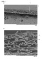
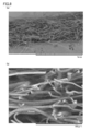
- FIG. 1 is a scanning electron microscope (SEM) photograph of a cross-section in the thickness direction of the nonwoven fabric of the present invention (Example 1 described later) (FIG. 1 (a) is enlarged 100 times, FIG. 1 (b). Is magnified 1000 times).
- the non-woven fabric of the present invention is a non-woven fabric 1 containing fibers mainly composed of a polymer having a Tg of 50 ° C. or higher, and the fibers 2 are partially fused (self-bonded). It has the fused part 3.
- the nonwoven fabric 1 of the present invention preferably has a fiber fusion rate of 15% or more, more preferably 20% or more, and further preferably 25% or more in the cross section in the thickness direction.
- the fiber fusion rate of the nonwoven fabric is preferably 60% or less, and 50% The following is more preferable.
- the fiber fusion rate of the nonwoven fabric described above can be calculated, for example, by the following procedure. First, using SEM, the photograph which expanded the cross section in the thickness direction of a nonwoven fabric 1000 times was image
- disconnection which fibers are fusing with respect to the number of fiber cut surfaces (fiber cross section) from this photograph visually. Find the ratio of the number of faces. Of the total number of fiber cross sections that can be found in each region, the ratio of the number of cross sections in which two or more fibers are fused is expressed by the following formula: Fiber fusion rate (%) (cross section of two or more fused fibers) Number) / (total number of fiber cross-sections) ⁇ 100.
- the average area of each part where the fibers are fused is preferably 70 ⁇ m 2 or less, more preferably 50 ⁇ m 2 or less.
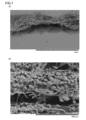
- FIGS. 6 to 8 show SEM photographs of cross sections in the thickness direction when a non-woven fabric produced by the melt blown method is post-processed.
- 6 shows a case where calendering is performed as post-processing (Comparative Example 3 to be described later) (FIG. 6A is enlarged 100 times, FIG. 6B is enlarged 1000 times), and FIG. 7 is embossed as post-processing.
- FIG. 7A is 100 times enlarged, FIG.
- FIG. 8 is a case where spunlace processing is performed as post-processing (described later). Comparative Example 4) (FIG. 8 (a) is enlarged 100 times, and FIG. 8 (b) is enlarged 1000 times).
- FIGS. 6B and 7B in the non-woven fabric subjected to calendering and embossing as post-processing, there are many portions where the fibers are fused to a state where it is difficult to determine the fiber diameter.
- the average area of each part formed and fused to the fiber is over 70 ⁇ m 2 .
- the average area of each part where the fibers are fused is 70 ⁇ m 2 or less, and as shown in FIG.
- the nonwoven fabric of the present invention preferably has an average fiber diameter in the range of 1 to 10 ⁇ m.
- the nonwoven fabric of the present invention preferably includes a fused portion where fibers are fused, but even in that case, when calendering is performed (see FIG. 6B), embossing is performed. Unlike the case where the processing is performed (see FIG. 7B), the fusion is such that the fiber diameter can be discriminated (FIG. 1B), and the average fiber diameter can be calculated.
- the average fiber diameter is less than 1 ⁇ m, it is necessary to reduce the discharge amount, the productivity is lowered, the discharge pressure becomes unstable, the yarn breakage, the polymer lump May occur frequently, making it difficult to form the web.
- the average fiber diameter of the nonwoven fabric of the present invention is more preferably in the range of 1.2 to 9.5 ⁇ m, for the reason of achieving both production stability and denseness, and preferably 1.5 to 9. A range of 0 ⁇ m is particularly preferable.
- the nonwoven fabric of this invention contains the fiber which has a polymer whose Tg is 50 degreeC or more as a main component.
- the fiber mainly composed of a polymer having a Tg of 50 ° C. or more is a fiber containing 50% by mass or more of a polymer having a Tg of 50 ° C. or more, and the content thereof is preferably 70% by mass or more. More preferably, it is 80 mass% or more, More preferably, it is 90 mass% or more, Most preferably, it is 100 mass%.
- the nonwoven fabric of the present invention may contain two or more different types of polymers having a Tg of 50 ° C. or more as long as the total of polymers having a Tg of 50 ° C. or more is 50% by mass or more.
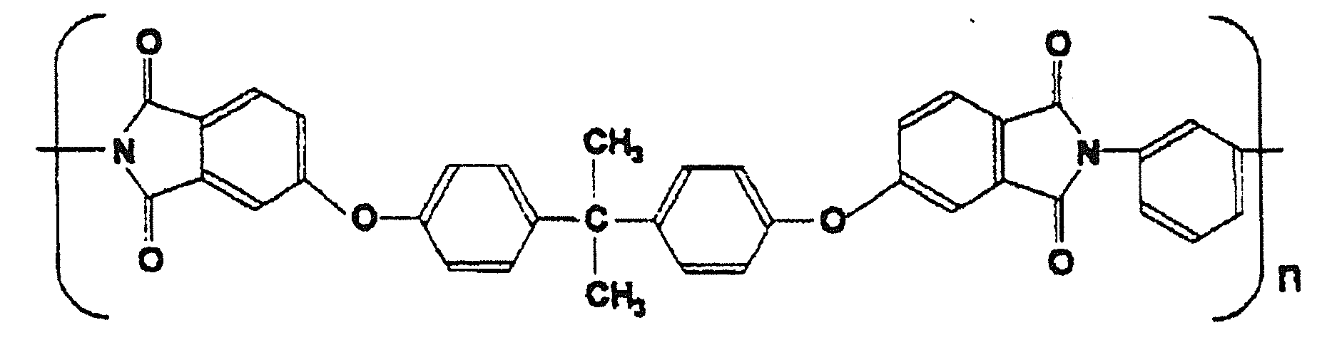
- polystyrene resin examples include polyamide, polyphenylene sulfide, polyethylene terephthalate, and polycarbonate. From the viewpoint of both flame retardancy and heat resistance, amorphous polyetherimide (PEI). Is particularly preferred.
- PEI amorphous polyetherimide
- Amorphous PEI used in the present invention is a polymer containing an aliphatic, alicyclic or aromatic ether unit and a cyclic imide as a repeating unit, and has an amorphous property and melt moldability. If it does not specifically limit.
- the main chain of amorphous PEI has a structural unit other than cyclic imide and ether bond, such as aliphatic, alicyclic or aromatic ester unit, oxycarbonyl unit, etc. It may be contained.
- a polymer represented by the following general formula is preferably used.
- R1 is a divalent aromatic residue having 6 to 30 carbon atoms
- R2 is a divalent aromatic residue having 6 to 30 carbon atoms, and 2 to 20 carbons.
- the amorphous PEI used in the present invention preferably has a melt viscosity at 330 ° C. of 100 to 3000 Pa ⁇ s.
- the melt viscosity at 330 ° C. is preferably 200 to 2700 Pa ⁇ s, and more preferably 300 to 2500 Pa ⁇ s.
- the amorphous PEI used in the present invention preferably has a glass transition temperature of 200 ° C. or higher.
- the glass transition temperature is less than 200 ° C.
- the resulting nonwoven fabric may have poor heat resistance.
- the higher the glass transition temperature of amorphous PEI the more preferable because a nonwoven fabric excellent in heat resistance can be obtained.
- the fusion temperature will be high when fused, and the polymer will be polymerized at the time of fusion. May cause decomposition.
- the glass transition temperature of amorphous PEI is more preferably 200 to 230 ° C, and further preferably 205 to 220 ° C.
- the molecular weight of the amorphous PEI used in the present invention is not particularly limited, but the weight average molecular weight (Mw) is 1000 considering the mechanical properties, dimensional stability, and process passability of the resulting fiber or nonwoven fabric. It is preferably ⁇ 80000.
- Mw weight average molecular weight
- the use of a polymer having a high molecular weight is preferable because it is excellent in terms of fiber strength, heat resistance and the like, but from the viewpoint of resin production cost, fiberization cost, etc., the weight average molecular weight is preferably 2000 to 50000, and 3000 to 40000. It is more preferable that
- amorphous PEI includes 2,2-bis [4- (2,3-dicarboxyl) mainly having a structural unit represented by the following formula.
- a condensate of phenoxy) phenyl] propane dianhydride with m-phenylenediamine or p-phenylenediamine is preferably used.
- This PEI is commercially available from Servic Innovative Plastics under the trademark “Ultem”.
- an antioxidant In the fiber mainly composed of a polymer having a Tg of 50 ° C. or more, which is contained in the nonwoven fabric of the present invention, an antioxidant, an antistatic agent, a radical inhibitor, a matting agent, and the like within a range not impairing the effects of the present invention.
- An ultraviolet absorber, a flame retardant, an inorganic substance, etc. may be included.
- inorganic substances include carbon nanotubes, fullerene, talc, wollastonite, zeolite, sericite, mica, kaolin, clay, pyrophyllite, silica, bentonite, alumina silicate and other silicates, silicon oxide, magnesium oxide, Metal oxides such as alumina, zirconium oxide, titanium oxide and iron oxide, carbonates such as calcium carbonate, magnesium carbonate and dolomite, sulfates such as calcium sulfate and barium sulfate, calcium hydroxide, magnesium hydroxide and aluminum hydroxide Hydroxides, glass beads, glass flakes, glass powders, ceramic beads, boron nitride, silicon carbide, carbon black, graphite and the like are used.
- an end group blocking agent such as a mono- or diepoxy compound, a mono- or polycarbodiimide compound, a mono- or dioxazoline compound, or a mono- or diazirine compound may be included.
- the nonwoven fabric of the present invention includes fibers other than fibers mainly composed of a polymer having a Tg of 50 ° C. or higher, for example, fibers made of polyethylene, polypropylene, ethylene vinyl acetate, and the like within a range not impairing the effects of the present invention. You may go out.
- the content of the fiber mainly composed of a polymer having a Tg of 50 ° C. or higher is not particularly limited, but is preferably 50% by mass or more, more preferably 70% by mass or more, and 90% by mass or more. More preferably, it is particularly preferably 100% by mass.
- the thickness of the nonwoven fabric of the present invention is not particularly limited, but is preferably in the range of 10 to 1000 ⁇ m, more preferably in the range of 15 to 500 ⁇ m, and in the range of 20 to 200 ⁇ m. It is particularly preferred. If the thickness of the nonwoven fabric is less than 10 ⁇ m, there is a risk that the strength will be low and it will break during processing, and if the thickness of the nonwoven fabric exceeds 1000 ⁇ m, it will be difficult to form a web. There is a fear.
- the nonwoven fabric of the present invention preferably has an air permeability of 10 cc / cm 2 / sec or more, more preferably 20 cc / cm 2 / sec or more, and 130 cc / cm 2 / sec or less. Preferably, it is 120 cc / cm 2 / sec or less. By being in the said range, it can use suitably also for uses, such as a filter.
- the basis weight of the nonwoven fabric of the present invention is not particularly limited, but is preferably in the range of 10 to 1000 g / m 2 , and more preferably in the range of 15 to 500 g / m 2 .
- the basis weight of the nonwoven fabric is less than 10 g / m 2 , there is a possibility that the strength becomes low and breaks during processing, and when the basis weight of the nonwoven fabric exceeds 1000 g / m 2 , productivity is increased. From the viewpoint of
- the present invention also provides a method for suitably producing the above-described nonwoven fabric of the present invention.
- the nonwoven fabric of the present invention described above is a nonwoven fabric including fibers mainly composed of a polymer having a Tg of 50 ° C. or higher and having a vertical strength per 1 g / m 2 of 1 N / 5 cm or more, and has a density of 0.00. 01 to 0.4 g / cm 3 , if the ratio of the portion where the density exceeds 0.4 g / cm 3 in the cross section in the thickness direction is 3% or less, the nonwoven fabric was produced by the method for producing a nonwoven fabric of the present invention.
- it is preferably manufactured by the method for manufacturing a nonwoven fabric of the present invention.
- the method for producing a nonwoven fabric of the present invention is carried out by performing the melt blown method while maintaining the temperature in at least one of the following (1) and (2) at a temperature higher by 10 ° C. or more than the Tg of the main polymer. It is characterized by.
- the polymer is held at a temperature that is 10 ° C. higher than the Tg of the polymer having the highest Tg.
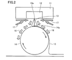
- FIG. 2 and FIG. 3 are schematic diagrams for explaining the principle of the method for producing a nonwoven fabric of the present invention.
- FIG. 2 shows a state where the meltblown method is performed using the meltblown device 11. After the polymer fiber 13 is discharged (spun) from the spinning nozzle 12 of the meltblown device 11, the meltblown device 11 captures it with a rotating roll 14. Collected to form a web (sheets made by overlapping fibers) 15. Hot air (primary air) 16 for spinning is discharged along with the polymer fiber 13 from the spinning nozzle 12 of the melt blown device 11 and flows along the curved surface of the roll 14.
- the inventors flow cold air as an accompanying flow 17 toward the spinning nozzle 12, so that the polymer fiber 13 discharged from the tip 12 a of the spinning nozzle 12 is on the surface of the roll 14 (spun). It was found that the web 15 having low strength and poor handleability was formed due to rapid cooling before reaching the fiber collection surface 14a. For this reason, conventionally, it has been necessary to perform post-processing such as calendering, embossing, and spunlace (hydraulic) processing to impart strength to the web to make a nonwoven fabric.
- the temperature of the primary air discharged from the tip of the spinning nozzle actually measured by the inventors was 420 ° C., but reached the collection surface of the spun fiber.
- the temperature of the primary air (measured using a contact-type temperature sensor) was 145 ° C.
- the radius x centered on the tip 12a of the spinning nozzle 12 is between the tip 12a of the spinning nozzle 12 and the collecting surface 14a of the spun fiber 13.
- the hemispherical space A of 0.5 ⁇ collection distance d around the nozzle tip and / or the tip 12a of the spinning nozzle 12 and the collection surface 14a of the spun fiber 13 are collected.
- the temperature at a point B (not shown) of 1 cm from the collection surface on the straight line is maintained at a temperature 10 ° C. higher than the Tg of the polymer.
- the temperature in either the space A or the point B may be maintained at a temperature higher by 10 ° C. or more than the Tg of the polymer. May be maintained at a temperature 15 ° C. or higher than the Tg of the polymer.
- a part of the space A and the point B may overlap.
- the nonwoven fabric of the present invention having a polymer as a main component and having fibers fused together and having sufficient strength can be produced without post-processing such as calendering, embossing, and spunlace processing (that is, The web 15 collected by the roll 14 can be used as a non-woven fabric as it is).
- 0.5 ⁇ collection distance d is a radius x.
- the radius x in the hemispherical space A centering on the tip 12a of the spinning nozzle 12 is preferably 3 to 12 cm, and particularly preferably 5 cm.
- the temperature in the space A can be measured by, for example, providing a thermocouple type thermometer as a thermometer at any position on the curved surface constituting the hemisphere assumed as the boundary of the space A, for example. .
- the temperature of the surrounding space is not particularly limited.
- the temperature in at least one of the space A and the point B is maintained at 10 ° C. or more (more preferably in the range of 15 to 60 ° C.) than the Tg of the polymer.
- the temperature in at least one of the space A and the point B is equal to or lower than the Tg of the polymer or less than 10 ° C. even if the temperature is higher than the Tg, the effect of preventing the spun fibers from being cooled by the accompanying flow Is insufficient, there is a risk of producing a nonwoven fabric with low strength and inferior handleability.
- FIG. 4 is a diagram schematically showing a preferred example of the method for producing a nonwoven fabric of the present invention.
- the tip 12a of the spinning nozzle 12 is blown toward the tip 12a of the spinning nozzle 12 so that hot air (this hot air is referred to as “secondary air”) 22 is blown toward the above-described primary air.
- a hot air jet device 21 is provided in the vicinity.
- the method of providing the hot air jetting device 21 is not particularly limited, the hot air jetting device 21 having a shape that continuously forms the circumference surrounding the tip 12a of the spinning nozzle 12 is used, and the blowing destination of the hot air jetting device 21 is that of the spinning nozzle 12.
- the melt blown method can be performed while maintaining the temperature in at least one of (1) and (2) at a temperature higher by 10 ° C. or more than the Tg of the polymer as described above. It becomes.
- a hot-air ejection apparatus 21 a conventionally well-known appropriate hot-air ejection apparatus can be especially used without a restriction
- the temperature of the secondary air 22 ejected by the hot air ejecting device 21 so as to blow into the tip 12a of the spinning nozzle 12 is the temperature in at least one of (1) and (2) (particularly, the space (1)). Is not particularly limited as long as it can be maintained at a temperature 30 ° C. or higher than the Tg of the polymer, but is preferably 35 to 70 ° C. higher than the polymer Tg, and 35 to 60 ° C. higher than the polymer Tg. It is more preferable. When the temperature of the secondary air 22 is less than 30 ° C. higher than the Tg of the polymer, the temperature is maintained in at least one of the above (1) and (2) (particularly the space (1)).
- the temperature in at least one of (1) and (2) can be maintained at a temperature higher by 10 ° C. or more than the Tg of the polymer. is not particularly limited if, in order not to disturb the flow of the primary air, preferably in the range of 3 ⁇ 12Nm 3 / m, and more preferably in a range of 4 ⁇ 10Nm 3 / m .
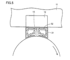
- FIG. 5 is a diagram schematically showing another preferred example of the method for producing a nonwoven fabric of the present invention.
- the cover 31 At least a part of the space between the tip 12 a of the spinning nozzle 12 and the collection surface 14 a of the spun fiber is covered with the cover 31.
- the primary air discharged from the tip 12a of the spinning nozzle 12 stays in the space covered by the cover 31 as the circulating air 32, and is not covered by such a cover 31,
- the primary air discharged from the tip 12a of the spinning nozzle 12 is not rapidly cooled by the accompanying flow.
- the melt blown method can be performed while maintaining the temperature in at least one of (1) and (2) at a temperature higher by 10 ° C.
- the cover 31 can be connected to the tip 12a of the spinning nozzle 12 and the spinning. It is not necessary to cover the entire area between the collected fibers 14a. As in the example shown in FIG. 5, the cover 31 is preferably provided so as to cover the entire area between the tip 12a of the spinning nozzle 12 and the collection surface 14a of the spun fiber.
- the material for forming such a cover 31 is not particularly limited as long as it has heat resistance that does not deteriorate due to the temperature of the primary air, and examples thereof include metals such as SUS, aluminum, and copper. However, SUS is preferable from the viewpoint of durability, workability, and heat resistance.
- the temperature in at least one of the above (1) and (2) is maintained at a temperature 10 ° C. or more higher than the Tg of the polymer, the melt blown method is performed, calendering, embossing, Except for not performing post-processing such as spunlace processing, the same processes and conditions as in the conventional meltblown method can be suitably employed.
- the spinning conditions include a spinning temperature of 300 to 500 ° C., a hot air temperature (primary air temperature) of 300 to 500 ° C., and an air amount of 5 to 25 Nm 3 per 1 m of the nozzle length. Of course not limited.
- Nonwoven fabric density (g / cm 3 )
- the volume of the nonwoven fabric was measured using [basis weight of nonwoven fabric] and [nonwoven fabric thickness], and the density of the nonwoven fabric was calculated from these results.
- the glass transition temperature was measured by measuring the temperature dependence of loss tangent (tan ⁇ ) at a frequency of 10 Hz and a heating rate of 10 ° C./min using a solid dynamic viscoelastic device “RheoSpectra DVE-V4” manufactured by Rheology. It was determined from the peak temperature.
- the peak temperature of tan ⁇ is a temperature at which the first derivative of the amount of change with respect to the temperature of the value of tan ⁇ becomes zero.
- Fiber fusion rate (%) (cross section of two or more fused fibers) Number) / (total number of fiber cross-sections) ⁇ 100.
- Fiber fusion rate (%) (cross section of two or more fused fibers) Number) / (total number of fiber cross-sections) ⁇ 100.
- each sample piece was measured at five locations with a digital thickness gauge (Toyo Seiki Seisakusho: B1 type) with a diameter of 16 mm and a load of 20 gf / cm 2. And the average value of 15 points
- a digital thickness gauge Toyo Seiki Seisakusho: B1 type
- Example 1 Amorphous polyetherimide having a melt viscosity of 500 Pa ⁇ s at 330 ° C. is used and extruded by an extruder.
- Nozzle hole diameter D (diameter) 0.3 mm, L (nozzle length) / D 10, nozzle hole Supplied to a melt blown device having nozzles with a pitch of 0.75 mm, sprayed at a single-hole discharge rate of 0.09 g / min, spinning temperature of 390 ° C., hot air (primary air) temperature of 420 ° C., nozzle width of 10 Nm 3 / min per 1 m of nozzle width, A nonwoven fabric having a basis weight of 25 g / m 2 was produced.
- a hot air blowing device such as the example shown in FIG. 4 is provided so that hot air (secondary air) is blown into the tip of the spinning nozzle of the melt blown device, and hot air (secondary air) at a temperature of 260 ° C. is 2 Nm 3 . Sprayed at the flow rate toward the tip of the spinning nozzle.
- thermometer The temperature measured by a thermometer (AD-5601A (manufactured by A & I Co.)) was 235 ° C. (that is, the space A was 20 ° C. higher than 215 ° C., which is the glass transition temperature of amorphous PEI). °C was kept high).
- a thermometer AD-5601A (A • 5A) provided so as to be located on the straight line 1 cm from the collection surface with respect to a linear distance d between the tip of the spinning nozzle and the collection surface of the spun fiber.
- i) was measured at 242 ° C. (ie, point B was held 27 ° C. higher than 215 ° C., the glass transition temperature of amorphous PEI). In this way, a nonwoven fabric was obtained without post-processing.
- FIG. 1 (a) shows an image magnified 100 times
- FIG. 1 (a) shows an image magnified 100 times
- the temperature measured by a thermometer located on the outer periphery of the shape is 253 ° C. (that is, the space A is kept 38 ° C.
- the temperature measured by a thermometer provided so as to be 1 cm from the collection surface on the straight line d with respect to the collection surface of the spun fiber is 261 ° C. (that is, the point B is The non-woven fabric was obtained in the same manner as in Example 1 except that the glass transition temperature of amorphous PEI was maintained at 46 ° C. higher than 215 ° C.
- Example 3 A nonwoven fabric was obtained in the same manner as in Example 2 except that the basis weight was 10 g / m 2 .
- Example 4 An amorphous polycarbonate having a melt viscosity at 300 ° C. of 100 Pa ⁇ s is used and extruded by an extruder.
- Nozzle hole diameter D (diameter) 0.3 mm, L (nozzle length) / D 10, nozzle hole pitch 0 Supplied to melt blown device with nozzle of .75mm, single hole discharge rate 0.09g / min, spinning temperature 340 ° C, hot air (primary air) temperature 370 ° C, sprayed at 10Nm 3 / min per 1m nozzle width, basis weight Produced a 25 g / m 2 nonwoven fabric.
- a hot air blowing device such as the example shown in FIG.
- hot air secondary air
- hot air secondary air
- the temperature measured by a thermometer (AD-5601A (manufactured by A & I Co., Ltd.)) was 185 ° C.
- thermometer (AD-5601A (A • 5A) provided so as to be located on the straight line 1 cm from the collection surface with respect to a linear distance d between the tip of the spinning nozzle and the collection surface of the spun fiber.
- the temperature measured by Andi Co. was 192 ° C. (that is, the point B was maintained 57 ° C. higher than the glass transition temperature of 135 ° C. of the amorphous polycarbonate).
- the nonwoven fabric of the present invention is excellent in handleability despite its low density, it can be used not only in combination with various substrates and other nonwoven fabrics, but also suitably used in filters that require air permeability.
Landscapes
- Engineering & Computer Science (AREA)
- Textile Engineering (AREA)
- Mechanical Engineering (AREA)
- Chemical & Material Sciences (AREA)
- Chemical Kinetics & Catalysis (AREA)
- Nonwoven Fabrics (AREA)
- General Chemical & Material Sciences (AREA)
Abstract
Description
(1)密度が0.01~0.4g/cm3であること。
(2)厚み方向の断面において密度が0.4g/cm3を超える部分の割合が3%以下であること。
本発明はまた、上述した本発明の不織布を製造する方法であって、(1)紡糸ノズルの先端と紡糸された繊維の捕集面との間の捕集距離dに対して、ノズル先端を中心として、0.5×捕集距離dの半球状の空間、ならびに、(2)紡糸ノズルの先端と紡糸された繊維の捕集面との間の捕集距離dに対して当該直線上で捕集面から1cmの点のうちの少なくともいずれかにおける温度をガラス転移温度より10℃以上高い温度に保持してメルトブローン法を行なう、不織布の製造方法についても提供する。
本発明の不織布は、1g/m2あたりのタテ強力(タテ方向(不織布製造における流れ方向)の強度)が1N/5cm以上である。本発明によれば、部分的に密度の高い箇所を生じてしまうカレンダー加工、エンボス加工、スパンレース加工などの後加工を施すことなく、単独で不織布として取り扱うことができる十分な強度を備えた不織布を得ることができる。本発明の不織布の強度は、1.2N/5cm以上であることがより好ましく、1.5N/5cmであることが更に好ましい。従来のメルトブローン法で不織布化し、カレンダー加工、エンボス加工、スパンレース加工などの後加工を行なわなかった場合(後述する比較例1)には、この1g/m2あたりのタテ強力が格段に劣ることになり、本発明の不織布は、このような場合と比較しても格段に取扱い性が優れる不織布である。
密度0.4g/cm3を超える箇所の割合(%)
=密度0.4g/cm3を超える箇所の長さ(mm)/10(mm)×100
でその割合を求める。なお、写真を観察して、密度が0.4g/cm3を超えているか否かは、SEMに付属している2点間距離測定の機能を使用し、密度が0.4g/cm3を超える箇所が占める長さを調べるというようにして判別する。
繊維融着率(%)=(2本以上融着した繊維の断面数)/(全繊維断面数)×100に基づいて百分率で表わす。ただし、各写真について、断面の見える繊維は全て計数し、繊維断面数100以下の場合は、観察する写真を追加して全繊維断面数が100を超えるようにする。また、繊維同士が接触する部分には、融着することなく単に接触している部分と、融着により接着している部分とがあるが、SEM写真撮影のために不織布を切断することにより、その断面においては各繊維が有する応力によって、単に接触している繊維同士は分離する。したがって、SEM写真において、接触している繊維同士が融着していると判断できる。
本発明において、Tgが50℃以上のポリマーを主成分とする繊維とは、Tgが50℃以上のポリマーを50質量%以上含む繊維であって、その含有量は好ましくは70質量%以上であり、より好ましくは80質量%以上であり、更に好ましくは90質量%以上であり、特に好ましくは100質量%である。

本発明は、上述した本発明の不織布を好適に製造する方法についても提供する。なお、上述した本発明の不織布は、Tgが50℃以上のポリマーを主成分とする繊維を含み、1g/m2あたりのタテ強力が1N/5cm以上である不織布であって、密度が0.01~0.4g/cm3、厚み方向の断面において密度が0.4g/cm3を超える部分の割合が3%以下であれば、本発明の不織布の製造方法によって製造されたものであっても本発明の不織布の製造方法によって製造されたものでなくともよいが、本発明の不織布の製造方法によって製造されたものであることが好ましい。
(2)紡糸ノズルの先端と紡糸された繊維の捕集面との間の捕集距離dに対して当該直線上で捕集面から1cmの点。
〔不織布の坪量〕と〔不織布厚み〕を用いて不織布の体積を測定し、これらの結果から不織布の密度を算出した。
走査型電子顕微鏡を用いて、不織布の厚み方向における断面を100倍に拡大した写真を撮影し、この写真を目視で幅方向に10mmの直線を観察し、この直線のうちに、密度0.4g/cm3を超える箇所が占める長さを測定し、以下の式
密度0.4g/cm3を超える箇所の割合(%)
=密度0.4g/cm3を超える箇所の長さ(mm)/10(mm)×100
でその割合を求める。なお、写真を観察して、密度が0.4g/cm3を超えているか否かはSEMに付属している2点間距離測定の機能を使用し、密度0.4g/cm3を超えている箇所の長さを調べる、というようにして判別する。
不織布を幅5cmにカットし、島津製作所製オートグラフを使用し、JIS L 1906に準じ、引張り速度10cm/分で伸長し、切断時の荷重値をタテ強力とした。
東洋精機キャピログラフ1B型を用いて、温度330℃、剪断速度r=1200sec-1の条件下で測定した。
ガラス転移温度は、レオロジ社製の固体動的粘弾性装置「レオスペクトラDVE-V4」を用い、周波数10Hz、昇温速度10℃/minで損失正接(tanδ)の温度依存性を測定し、そのピーク温度から求めた。ここで、tanδのピーク温度とは、tanδの値の温度に対する変化量の第一次微分値がゼロとなる温度のことである。
走査型電子顕微鏡を用いて、不織布の厚み方向における断面を1000倍に拡大した写真を撮影し、この写真から目視で繊維切断面(繊維断面)の数に対して繊維同士が融着している切断面の数の割合を求めた。各領域に見出せる全繊維断面数のうち、2本以上の繊維が融着した状態の断面の数の占める割合を以下の式
繊維融着率(%)=(2本以上融着した繊維の断面数)/(全繊維断面数)×100に基づいて百分率で表わした。ただし、各写真について、断面の見える繊維は全て計数し、繊維断面数100以下の場合は、観察する写真を追加して全繊維断面数が100を超えるようにした。
走査型電子顕微鏡を用いて、不織布の厚み方向における断面を1000倍に拡大した写真を撮影し、この写真から、繊維が融着した部分の面積を算出し、その総計を繊維が融着した部分の個数で除して、平均値を求めた。
不織布を走査型電子顕微鏡で拡大撮影し、任意の100本の繊維の径を測定し、平均値を算出し、平均繊維径とした。
JIS L 1913に準じ、縦20cm×横20cmの試料片を採取し、電子天秤にて質量を測定し、試験片面積400cm2で除して、単位面積当たりの質量を坪量とした。
JIS L 1913に準じ、目付け測定と同試料片を用い、各試料片において、直径16mm、荷重20gf/cm2のデジタル測厚計((株)東洋精機製作所製:B1型)で各5箇所測定し、15点の平均値をシートの厚みとした。
通気度JIS L1913「一般不織布試験方法」のフラジール形法に準拠して測定した。
330℃での溶融粘度が500Pa・sである非晶性ポリエーテルイミドを使用し、押し出し機により押し出し、ノズル孔径D(直径)0.3mm、L(ノズル長さ)/D=10、ノズル孔ピッチ0.75mmのノズルを有するメルトブローン装置に供給し、単孔吐出量0.09g/分、紡糸温度390℃、熱風(一次エアー)温度420℃、ノズル幅1mあたり10Nm3/分で吹き付けて、坪量が25g/m2の不織布を製造した。この際、図4に示す例のような熱風噴出装置をメルトブローン装置の紡糸ノズルの先端に熱風(二次エアー)が吹き込むように設け、260℃の温度の熱風(二次エアー)を2Nm3の流量で、紡糸ノズルの先端に向かって吹きつけた。紡糸ノズルの先端と紡糸された繊維を受け取るローラの受け面との間の直線距離dは10cmであり、紡糸ノズルの先端を中心とする半径x=5cmの半球状の外周に位置するように設けた温度計(AD-5601A(エー・アンド・アイ社製))により測定された温度は235℃であった(すなわち、空間Aは、非晶性PEIのガラス転移温度である215℃よりも20℃高く保持されていた)。また、紡糸ノズルの先端と紡糸された繊維の捕集面との間の直線距離dに対し当該直線上で捕集面から1cmに位置するように設けられた温度計(AD-5601A(エー・アンド・アイ社製))により測定された温度は242℃であった(すなわち、点Bは、非晶性PEIのガラス転移温度である215℃よりも27℃高く保持されていた)。このようにして後加工を行なうことなく、不織布を得た。得られた不織布の厚み方向の断面のSEM写真として、100倍拡大したものを図1(a)、1000倍拡大したものを図1(b)に示す。
330℃での溶融粘度が900Pa・sである非晶性ポリエーテルイミドを使用し、紡糸温度を420℃、平均繊維径を3.7μm、紡糸ノズルの先端を中心とする半径x=5cmの半球状の外周に位置する温度計により測定された温度が253℃であり(すなわち、空間Aは、非晶性PEIのガラス転移温度である215℃よりも38℃高く保持)、紡糸ノズルの先端と紡糸された繊維の捕集面との間の直線距離dに対し当該直線上で捕集面から1cmに位置するように設けられた温度計により測定された温度が261℃(すなわち、点Bは、非晶性PEIのガラス転移温度である215℃よりも46℃高く保持)であったこと以外は実施例1と同様に行ない、不織布を得た。
坪量を10g/m2としたこと以外は実施例2と同様にして不織布を得た。
300℃での溶融粘度が100Pa・sである非晶性ポリカーボネートを使用し、押し出し機により押し出し、ノズル孔径D(直径)0.3mm、L(ノズル長さ)/D=10、ノズル孔ピッチ0.75mmのノズルを有するメルトブローン装置に供給し、単孔吐出量0.09g/分、紡糸温度340℃、熱風(一次エアー)温度370℃、ノズル幅1mあたり10Nm3/分で吹き付けて、坪量が25g/m2の不織布を製造した。この際、図4に示す例のような熱風噴出装置をメルトブローン装置の紡糸ノズルの先端に熱風(二次エアー)が吹き込むように設け、210℃の温度の熱風(二次エアー)を2Nm3の流量で、紡糸ノズルの先端に向かって吹きつけた。紡糸ノズルの先端と紡糸された繊維を受け取るローラの受け面との間の直線距離dは10cmであり、紡糸ノズルの先端を中心とする半径x=5cmの半球状の外周に位置するように設けた温度計(AD-5601A(エー・アンド・アイ社製))により測定された温度は185℃であった(すなわち、空間Aは、非晶性ポリカーボネートのガラス転移温度である135℃よりも50℃高く保持されていた)。また、紡糸ノズルの先端と紡糸された繊維の捕集面との間の直線距離dに対し当該直線上で捕集面から1cmに位置するように設けられた温度計(AD-5601A(エー・アンド・アイ社製))により測定された温度は192℃であった(すなわち、点Bは、非晶性ポリカーボネートのガラス転移温度である135℃よりも57℃高く保持されていた)。
熱風噴出装置を設けなかったこと以外は実施例2と同様にして不織布を得た(紡糸ノズルの先端を中心とする半径x=5cmの半球状の外周に位置する温度計により測定された温度は41℃、紡糸ノズルの先端と紡糸された繊維の捕集面との間の直線距離dに対し当該直線上で捕集面から1cmに位置するように設けられた温度計により測定された温度は110℃)。
エンボス加工装置を用いて、比較例1で得られた不織布に、後加工としてエンボス加工を格子柄のエンボスロールにて、ロール温度180℃、線圧50kg/cm、速度1m/minという条件で行なった。得られた不織布の厚み方向の断面のSEM写真として、100倍拡大したものを図7(a)、1000倍拡大したものを図7(b)に示す。
カレンダー加工装置(鉄ロール)を用いて、比較例1で得られた不織布に、後加工としてカレンダー加工を、ロール温度180℃、線圧216kg/cm、速度3.2m/minという条件で行なった。得られた不織布の厚み方向の断面のSEM写真として、100倍拡大したものを図6(a)、1000倍拡大したものを図6(b)に示す。
水流絡合加工装置を用いて、比較例1で得られた不織布に、後加工として水流絡合加工を、速度5.0m/minで、孔径0.1mmφノズルを使用し、0.5MPa、2.0MPa、2.5MPaの3段階で水流絡合処理を行なった。得られた不織布の厚み方向の断面のSEM写真として、100倍拡大したものを図8(a)、1000倍拡大したものを図8(b)に示す。
熱風(二次エアー)の温度を240℃にしたこと以外は実施例2と同様の条件で不織布を得た。紡糸ノズルの先端を中心とする半径x=5cmの半球状の外周に位置する温度計により測定された温度は220℃、紡糸ノズルの先端と紡糸された繊維の捕集面との間の直線距離dに対し当該直線上で捕集面から1cmに位置するように設けられた温度計により測定された温度は217℃であった。


Claims (5)
- ガラス転移温度が50℃以上のポリマーを主成分とする繊維を含み、1g/m2あたりのタテ強力が1N/5cm以上である不織布であって、以下の(1)~(2)を全て満足する不織布。
(1)密度が0.01~0.4g/cm3であること。
(2)厚み方向の断面において密度が0.4g/cm3を超える部分の割合が3%以下であること。 - 厚み方向の断面において繊維融着率が15%以上、かつ、繊維が融着した各部分の面積の平均が70μm2以下である、請求項1に記載の不織布。
- 平均繊維径が1~10μmである、請求項1に記載の不織布。
- 非晶性ポリエーテルイミド系繊維を含有する、請求項1に記載の不織布。
- 請求項1~4のいずれか1項に記載の不織布を製造する方法であって、
(1)紡糸ノズルの先端と紡糸された繊維の捕集面との間の捕集距離dに対して、ノズル先端を中心として、0.5×捕集距離dの半球状の空間、ならびに、
(2)紡糸ノズルの先端と紡糸された繊維の捕集面との間の捕集距離dに対して当該直線上で捕集面から1cmの点
のうちの少なくともいずれかにおける温度をガラス転移温度より10℃以上高い温度に保持してメルトブローン法を行なう、不織布の製造方法。
Priority Applications (5)
| Application Number | Priority Date | Filing Date | Title |
|---|---|---|---|
| KR1020187002761A KR102403836B1 (ko) | 2015-06-30 | 2016-06-30 | 부직포 및 그 제조 방법 |
| CN201680038212.6A CN107709646B (zh) | 2015-06-30 | 2016-06-30 | 无纺布及其制造方法 |
| JP2017526434A JP6617148B2 (ja) | 2015-06-30 | 2016-06-30 | 不織布およびその製造方法 |
| EP16818032.1A EP3318667B1 (en) | 2015-06-30 | 2016-06-30 | Nonwoven fabric and production method for same |
| US15/739,920 US20180187353A1 (en) | 2015-06-30 | 2016-06-30 | Nonwoven fabric and method for producing the same |
Applications Claiming Priority (2)
| Application Number | Priority Date | Filing Date | Title |
|---|---|---|---|
| JP2015131693 | 2015-06-30 | ||
| JP2015-131693 | 2015-06-30 |
Publications (1)
| Publication Number | Publication Date |
|---|---|
| WO2017002924A1 true WO2017002924A1 (ja) | 2017-01-05 |
Family
ID=57608157
Family Applications (1)
| Application Number | Title | Priority Date | Filing Date |
|---|---|---|---|
| PCT/JP2016/069462 Ceased WO2017002924A1 (ja) | 2015-06-30 | 2016-06-30 | 不織布およびその製造方法 |
Country Status (7)
| Country | Link |
|---|---|
| US (1) | US20180187353A1 (ja) |
| EP (1) | EP3318667B1 (ja) |
| JP (1) | JP6617148B2 (ja) |
| KR (1) | KR102403836B1 (ja) |
| CN (1) | CN107709646B (ja) |
| TW (1) | TWI675947B (ja) |
| WO (1) | WO2017002924A1 (ja) |
Cited By (2)
| Publication number | Priority date | Publication date | Assignee | Title |
|---|---|---|---|---|
| WO2017170791A1 (ja) * | 2016-03-30 | 2017-10-05 | 株式会社クラレ | 耐熱性繊維構造体 |
| US12553095B2 (en) | 2020-11-23 | 2026-02-17 | Savanna Ingredients Gmbh | Dried allulose crystals |
Families Citing this family (4)
| Publication number | Priority date | Publication date | Assignee | Title |
|---|---|---|---|---|
| TWI621744B (zh) * | 2015-10-20 | 2018-04-21 | 聚泰環保材料科技股份有限公司 | 製備石墨烯摻混天然纖維素紡黏不織布的方法 |
| TWI588089B (zh) * | 2015-10-20 | 2017-06-21 | Acelon Chem & Fiber Corp | 製備石墨烯摻混天然纖維素熔噴不織布的方法 |
| CN113597482A (zh) * | 2019-03-19 | 2021-11-02 | 富士胶片株式会社 | 无纺布制造方法 |
| CN113950547A (zh) * | 2019-03-29 | 2022-01-18 | 株式会社钟化 | 熔喷无纺布的制造方法及熔喷无纺布 |
Citations (6)
| Publication number | Priority date | Publication date | Assignee | Title |
|---|---|---|---|---|
| JPS63315655A (ja) * | 1987-06-16 | 1988-12-23 | 東レ株式会社 | ポリフェニレンサルファイドメルトブロ−不織布およびその製法 |
| JPH05279947A (ja) * | 1992-03-25 | 1993-10-26 | Kuraray Co Ltd | ポリカーボネート極細繊維不織布 |
| JPH0860515A (ja) * | 1994-08-22 | 1996-03-05 | Toray Ind Inc | メルトブロー不織布およびその製造方法 |
| JP2004185860A (ja) * | 2002-11-29 | 2004-07-02 | Mitsubishi Paper Mills Ltd | 電池用セパレータ |
| JP2008081893A (ja) * | 2006-09-28 | 2008-04-10 | Tapyrus Co Ltd | ポリエーテルエーテルケトン製メルトブロー不織布、その製造方法及びそれからなる耐熱性電池セパレータ |
| JP2012041644A (ja) * | 2010-08-17 | 2012-03-01 | Kuraray Co Ltd | 難熱性不織布及びそれを加熱してなる成形体 |
Family Cites Families (11)
| Publication number | Priority date | Publication date | Assignee | Title |
|---|---|---|---|---|
| US4315965A (en) * | 1980-06-20 | 1982-02-16 | Scott Paper Company | Method of making nonwoven fabric and product made thereby having both stick bonds and molten bonds |
| JP3650505B2 (ja) * | 1997-02-27 | 2005-05-18 | 帝人テクノプロダクツ株式会社 | メルトブロー不織布 |
| US6613268B2 (en) * | 2000-12-21 | 2003-09-02 | Kimberly-Clark Worldwide, Inc. | Method of increasing the meltblown jet thermal core length via hot air entrainment |
| US8349232B2 (en) * | 2006-03-28 | 2013-01-08 | North Carolina State University | Micro and nanofiber nonwoven spunbonded fabric |
| JP4229293B2 (ja) * | 2006-06-12 | 2009-02-25 | 株式会社立花商店 | クリーニングウエッブの製造方法、クリーニングウエッブ、画像形成装置及び定着装置 |
| KR20100133834A (ko) * | 2009-06-12 | 2010-12-22 | 웅진케미칼 주식회사 | 저융점사를 포함하는 원단 |
| US20110076907A1 (en) * | 2009-09-25 | 2011-03-31 | Glew Charles A | Apparatus and method for melt spun production of non-woven fluoropolymers or perfluoropolymers |
| CN102505349B (zh) * | 2011-10-11 | 2014-04-09 | 宁波市瑞通新材料科技有限公司 | 一种超薄无纺布 |
| JP6049967B2 (ja) * | 2012-10-30 | 2016-12-21 | 株式会社化繊ノズル製作所 | 極細繊維不織布の製造装置 |
| US9963810B2 (en) * | 2013-06-28 | 2018-05-08 | Kuraray Co., Ltd. | Flame retardant nonwoven fabric, formed product, and composite stack |
| JP6542787B2 (ja) * | 2013-11-26 | 2019-07-10 | スリーエム イノベイティブ プロパティズ カンパニー | 寸法安定性メルトブローン不織布繊維構造とその製造方法及び製造装置 |
-
2016
- 2016-06-30 CN CN201680038212.6A patent/CN107709646B/zh active Active
- 2016-06-30 WO PCT/JP2016/069462 patent/WO2017002924A1/ja not_active Ceased
- 2016-06-30 US US15/739,920 patent/US20180187353A1/en not_active Abandoned
- 2016-06-30 EP EP16818032.1A patent/EP3318667B1/en active Active
- 2016-06-30 TW TW105120784A patent/TWI675947B/zh active
- 2016-06-30 JP JP2017526434A patent/JP6617148B2/ja active Active
- 2016-06-30 KR KR1020187002761A patent/KR102403836B1/ko active Active
Patent Citations (6)
| Publication number | Priority date | Publication date | Assignee | Title |
|---|---|---|---|---|
| JPS63315655A (ja) * | 1987-06-16 | 1988-12-23 | 東レ株式会社 | ポリフェニレンサルファイドメルトブロ−不織布およびその製法 |
| JPH05279947A (ja) * | 1992-03-25 | 1993-10-26 | Kuraray Co Ltd | ポリカーボネート極細繊維不織布 |
| JPH0860515A (ja) * | 1994-08-22 | 1996-03-05 | Toray Ind Inc | メルトブロー不織布およびその製造方法 |
| JP2004185860A (ja) * | 2002-11-29 | 2004-07-02 | Mitsubishi Paper Mills Ltd | 電池用セパレータ |
| JP2008081893A (ja) * | 2006-09-28 | 2008-04-10 | Tapyrus Co Ltd | ポリエーテルエーテルケトン製メルトブロー不織布、その製造方法及びそれからなる耐熱性電池セパレータ |
| JP2012041644A (ja) * | 2010-08-17 | 2012-03-01 | Kuraray Co Ltd | 難熱性不織布及びそれを加熱してなる成形体 |
Cited By (4)
| Publication number | Priority date | Publication date | Assignee | Title |
|---|---|---|---|---|
| WO2017170791A1 (ja) * | 2016-03-30 | 2017-10-05 | 株式会社クラレ | 耐熱性繊維構造体 |
| JPWO2017170791A1 (ja) * | 2016-03-30 | 2019-02-14 | 株式会社クラレ | 耐熱性繊維構造体 |
| JP7141334B2 (ja) | 2016-03-30 | 2022-09-22 | 株式会社クラレ | 耐熱性繊維構造体 |
| US12553095B2 (en) | 2020-11-23 | 2026-02-17 | Savanna Ingredients Gmbh | Dried allulose crystals |
Also Published As
| Publication number | Publication date |
|---|---|
| JP6617148B2 (ja) | 2019-12-11 |
| KR20180022911A (ko) | 2018-03-06 |
| CN107709646A (zh) | 2018-02-16 |
| US20180187353A1 (en) | 2018-07-05 |
| KR102403836B1 (ko) | 2022-05-30 |
| TW201713809A (zh) | 2017-04-16 |
| JPWO2017002924A1 (ja) | 2018-04-19 |
| TWI675947B (zh) | 2019-11-01 |
| EP3318667B1 (en) | 2020-05-06 |
| EP3318667A4 (en) | 2018-11-14 |
| EP3318667A1 (en) | 2018-05-09 |
| CN107709646B (zh) | 2021-07-16 |
Similar Documents
| Publication | Publication Date | Title |
|---|---|---|
| JP6617148B2 (ja) | 不織布およびその製造方法 | |
| KR102277601B1 (ko) | 대전 부직포 및 그것을 사용한 여과재, 대전 부직포의 제조 방법 | |
| US9963810B2 (en) | Flame retardant nonwoven fabric, formed product, and composite stack | |
| TWI759493B (zh) | 纖維構造體及其製造方法,以及成形體及吸音材料 | |
| JP5307776B2 (ja) | 難熱性不織布及びそれを加熱してなる成形体 | |
| JP6487904B2 (ja) | 絶縁性不織布およびその製造方法、絶縁材 | |
| JP6617058B2 (ja) | メルトブロー不織布及び吸音材 | |
| JP6113953B2 (ja) | フィルター材およびフィルター複合材 | |
| JP2013136856A (ja) | 吸油シートおよび吸油複合シート | |
| JP2009074196A (ja) | 不織布及びその製造方法 |
Legal Events
| Date | Code | Title | Description |
|---|---|---|---|
| 121 | Ep: the epo has been informed by wipo that ep was designated in this application |
Ref document number: 16818032 Country of ref document: EP Kind code of ref document: A1 |
|
| ENP | Entry into the national phase |
Ref document number: 2017526434 Country of ref document: JP Kind code of ref document: A |
|
| NENP | Non-entry into the national phase |
Ref country code: DE |
|
| ENP | Entry into the national phase |
Ref document number: 20187002761 Country of ref document: KR Kind code of ref document: A |
|
| WWE | Wipo information: entry into national phase |
Ref document number: 2016818032 Country of ref document: EP |