WO2017006466A1 - 空気調和機の室内機 - Google Patents
空気調和機の室内機 Download PDFInfo
- Publication number
- WO2017006466A1 WO2017006466A1 PCT/JP2015/069687 JP2015069687W WO2017006466A1 WO 2017006466 A1 WO2017006466 A1 WO 2017006466A1 JP 2015069687 W JP2015069687 W JP 2015069687W WO 2017006466 A1 WO2017006466 A1 WO 2017006466A1
- Authority
- WO
- WIPO (PCT)
- Prior art keywords
- unit
- heat exchanger
- drain pan
- drain
- antibacterial
- Prior art date
- Legal status (The legal status is an assumption and is not a legal conclusion. Google has not performed a legal analysis and makes no representation as to the accuracy of the status listed.)
- Ceased
Links
Images




Classifications
-
- F—MECHANICAL ENGINEERING; LIGHTING; HEATING; WEAPONS; BLASTING
- F25—REFRIGERATION OR COOLING; COMBINED HEATING AND REFRIGERATION SYSTEMS; HEAT PUMP SYSTEMS; MANUFACTURE OR STORAGE OF ICE; LIQUEFACTION SOLIDIFICATION OF GASES
- F25D—REFRIGERATORS; COLD ROOMS; ICE-BOXES; COOLING OR FREEZING APPARATUS NOT OTHERWISE PROVIDED FOR
- F25D21/00—Defrosting; Preventing frosting; Removing condensed or defrost water
- F25D21/14—Collecting or removing condensed and defrost water; Drip trays
-
- F—MECHANICAL ENGINEERING; LIGHTING; HEATING; WEAPONS; BLASTING
- F24—HEATING; RANGES; VENTILATING
- F24F—AIR-CONDITIONING; AIR-HUMIDIFICATION; VENTILATION; USE OF AIR CURRENTS FOR SCREENING
- F24F13/00—Details common to, or for air-conditioning, air-humidification, ventilation or use of air currents for screening
- F24F13/22—Means for preventing condensation or evacuating condensate
- F24F13/222—Means for preventing condensation or evacuating condensate for evacuating condensate
-
- B—PERFORMING OPERATIONS; TRANSPORTING
- B65—CONVEYING; PACKING; STORING; HANDLING THIN OR FILAMENTARY MATERIAL
- B65D—CONTAINERS FOR STORAGE OR TRANSPORT OF ARTICLES OR MATERIALS, e.g. BAGS, BARRELS, BOTTLES, BOXES, CANS, CARTONS, CRATES, DRUMS, JARS, TANKS, HOPPERS, FORWARDING CONTAINERS; ACCESSORIES, CLOSURES, OR FITTINGS THEREFOR; PACKAGING ELEMENTS; PACKAGES
- B65D1/00—Rigid or semi-rigid containers having bodies formed in one piece, e.g. by casting metallic material, by moulding plastics, by blowing vitreous material, by throwing ceramic material, by moulding pulped fibrous material or by deep-drawing operations performed on sheet material
- B65D1/40—Details of walls
-
- F—MECHANICAL ENGINEERING; LIGHTING; HEATING; WEAPONS; BLASTING
- F24—HEATING; RANGES; VENTILATING
- F24F—AIR-CONDITIONING; AIR-HUMIDIFICATION; VENTILATION; USE OF AIR CURRENTS FOR SCREENING
- F24F1/00—Room units for air-conditioning, e.g. separate or self-contained units or units receiving primary air from a central station
- F24F1/0007—Indoor units, e.g. fan coil units
-
- F—MECHANICAL ENGINEERING; LIGHTING; HEATING; WEAPONS; BLASTING
- F24—HEATING; RANGES; VENTILATING
- F24F—AIR-CONDITIONING; AIR-HUMIDIFICATION; VENTILATION; USE OF AIR CURRENTS FOR SCREENING
- F24F1/00—Room units for air-conditioning, e.g. separate or self-contained units or units receiving primary air from a central station
- F24F1/0007—Indoor units, e.g. fan coil units
- F24F1/0043—Indoor units, e.g. fan coil units characterised by mounting arrangements
- F24F1/0047—Indoor units, e.g. fan coil units characterised by mounting arrangements mounted in the ceiling or at the ceiling
-
- F—MECHANICAL ENGINEERING; LIGHTING; HEATING; WEAPONS; BLASTING
- F24—HEATING; RANGES; VENTILATING
- F24F—AIR-CONDITIONING; AIR-HUMIDIFICATION; VENTILATION; USE OF AIR CURRENTS FOR SCREENING
- F24F13/00—Details common to, or for air-conditioning, air-humidification, ventilation or use of air currents for screening
- F24F13/30—Arrangement or mounting of heat-exchangers
-
- F—MECHANICAL ENGINEERING; LIGHTING; HEATING; WEAPONS; BLASTING
- F24—HEATING; RANGES; VENTILATING
- F24F—AIR-CONDITIONING; AIR-HUMIDIFICATION; VENTILATION; USE OF AIR CURRENTS FOR SCREENING
- F24F13/00—Details common to, or for air-conditioning, air-humidification, ventilation or use of air currents for screening
- F24F13/22—Means for preventing condensation or evacuating condensate
- F24F2013/221—Means for preventing condensation or evacuating condensate to avoid the formation of condensate, e.g. dew
-
- F—MECHANICAL ENGINEERING; LIGHTING; HEATING; WEAPONS; BLASTING
- F24—HEATING; RANGES; VENTILATING
- F24F—AIR-CONDITIONING; AIR-HUMIDIFICATION; VENTILATION; USE OF AIR CURRENTS FOR SCREENING
- F24F13/00—Details common to, or for air-conditioning, air-humidification, ventilation or use of air currents for screening
- F24F13/22—Means for preventing condensation or evacuating condensate
- F24F2013/228—Treatment of condensate, e.g. sterilising
Definitions
- the present invention relates to an indoor unit of an air conditioner, and more particularly to an indoor unit of a ceiling-embedded air conditioner.
- an indoor unit of an air conditioner there is a type (ceiling recessed type) in which the indoor unit is embedded in the ceiling.
- the indoor unit of the ceiling-embedded air conditioner sucks the air in the room by rotating a centrifugal fan, cools the sucked air with a heat exchanger, and cools the room by blowing it out from the outlet.
- drain water is generated in the heat exchanger during the cooling operation, and the drain water is accumulated in the drain pan and discharged out of the indoor unit by the drain pump.
- the drain pump can not drain drain water below its suction limit height, a certain amount of drain water always remains in the drain pan after the operation is stopped. Bacteria may be propagated to the remaining drain water to generate slime in the muddy water, which may cause clogging of the drain pump.
- the antimicrobial agent is often installed near the drain pump where the drain water collects in the drain pan in order to efficiently disinfect the drain water.
- a float switch is installed near the drain pump to prevent overflow of the drain water from the drain pan. Therefore, a space for installing the antibacterial agent is newly required at the place on the drain pan where such various parts are installed.
- the drain pan widening (increasing) the drain pan to provide an installation space for the antimicrobial agent in the vicinity of the drain pump on the drain pan reduces the cross-sectional area of the air path of the cooling air formed between the drain pan and the main body case. It will be done. This leads to an increase in noise and an increase in fan power.
- the same drain pump, float switch, and antibacterial agent as in a standard indoor unit are generally used, so the ratio of the space occupied by these components to the entire drain pan increases, and disconnection of the blowoff air path The reduction of the area is further increased.
- the present invention has been made in view of the above-described circumstances, and it is an object of the present invention to provide an indoor unit of an air conditioner in which an antibacterial agent is installed on a drain pan while suppressing a reduction in the cross-sectional area of the air passage. Do.
- an indoor unit of an air conditioner includes a blower fan provided in a housing, a heat exchanger that encloses the discharge direction of air from the blower fan, and the heat exchanger
- a drain pan disposed below and an antimicrobial unit disposed on the drain pan and having an antimicrobial agent that disinfects drain water, at least a portion of the antimicrobial unit being disposed immediately below the heat exchanger .
- the indoor unit of the air conditioner which installed the antibacterial agent on the drain pan can be provided, suppressing reduction of the cross-sectional area of a blowing air path.
- FIG. 8 is a cross-sectional view taken along the line AA of FIG. 7;
- FIG. 8 is a cross-sectional view taken along the line BB of FIG. 7; It is a figure for demonstrating the modification of this embodiment.
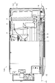
- FIG. 1 is a half cross-sectional view of an air conditioner indoor unit (hereinafter, also simply referred to as “indoor unit”) 100 according to an embodiment of the present invention.
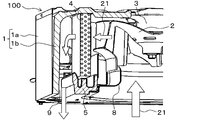
- FIG. 2 is a cross-sectional perspective view for explaining the flow of air in the indoor unit 100 shown in FIG. FIG. 2 shows a state in which the decorative panel 42 (see FIG. 1) is removed.
- the indoor unit 100 is an indoor unit of a type (ceiling-embedded type) embedded in a ceiling 41.
- the indoor unit 100 and the outdoor unit are connected by a refrigerant pipe (not shown) to form a refrigeration cycle to perform air conditioning.
- the indoor unit 100 has a main body case 1 and a decorative panel 42.
- the lower surface of the decorative panel 42 faces the room, and the main body case 1 is disposed to be embedded in the ceiling 41.
- the decorative panel 42 is attached below the main body case 1 so as to be substantially flush with the surface of the ceiling 41.
- the main body case 1 is installed and fixed on the ceiling back (above the surface of the ceiling 41) using a hanging bracket and a hanging bolt (not shown).
- the decorative panel 42 is fixed to the main body case 1 using a screw member (not shown) or the like.
- the main body case 1 includes a housing 1a and a heat insulating material 1b.
- the housing 1a has a rectangular shape in a plan view, and is formed in a bottomed box shape having an opening at the lower side using a metal plate.
- “rectangular” is a concept including “substantially rectangular” in which, for example, corners are chamfered or rounded in addition to “strict rectangular”.
- the housing 1a is formed by pressing two or more sheet metals into a predetermined shape and joining them by screws, rivets, and the like.
- a heat insulating material 1 b for heat insulation, condensation prevention, sound insulation, and the like is disposed in the inside of the housing 1 a with the opening facing downward.
- the indoor unit 100 includes a blower fan 2 provided in the housing 1 a, a heat exchanger 4 surrounding the discharge direction of air from the blower fan 2, and a drain pan 5 disposed below the heat exchanger 4.
- the blower fan 2 is, for example, a centrifugal fan, changes the direction of the air flow by approximately 90 degrees, and sends it to the heat exchanger 4.
- the blower fan 2 is rotationally driven by a fan motor 3 provided in the housing 1a.
- the fan motor 3 is fixed to the top plate of the housing 1a.
- the blower fan 2 and the fan motor 3 constitute a blower.
- the drain pan 5 receives and collects drain water that condenses and drips on the surface of the heat exchanger 4.
- the drain pan 5 is, for example, a foamed polystyrene molded product, and a resin layer made of a resin such as an ABS resin is formed on the inner surface side in contact with the drain water.
- an air inlet 6 is provided at the center of the lower surface of the indoor unit 100. Further, at the periphery of the lower surface of the indoor unit 100, air outlets 7 (here, four places) are provided.
- the blower fan 2 is provided in an air passage in a housing 1 a that connects the suction port 6 and the blowout port 7.
- the heat exchanger 4 is disposed between the blower fan 2 and the blower outlet 7.
- a bell mouth 8 is provided between the blower fan 2 and the suction port 6.
- the indoor air 21 is sucked from the suction port 6 (see FIG. 1) by the rotational operation of the blower fan 2, passes through the blower fan 2 and is blown out toward the heat exchanger 4.
- the air 21 is cooled by passing through the heat exchanger 4.
- the air 21 which has been cooled by leaving the heat exchanger 4 passes through the blowout air passage 9 formed between the drain pan 5 and the heat insulating material 1b of the main body case 1 and passes through the blowout port 7 (see FIG. 1)
- the air is blown out from the indoor unit 100 into the room.
- FIG. 3 is a cross-sectional perspective view showing the vicinity of the drain pump 14 of the indoor unit 100 shown in FIG.
- FIG. 4 is a perspective view for explaining the installation state of the antibacterial unit 15 on the drain pan 5.
- FIG. 5 is a plan view for explaining the installation state of the antibacterial unit 15 on the drain pan 5.
- the display of the heat exchanger 4 is abbreviate
- the drain pan 5 is a primary space and a downstream located on the upstream side (primary side) of the flow of the air 21 (see FIG. 2, hereinafter the same) of the heat exchanger 4 on the drain pan 5. It has the partition wall 12 which divides the secondary space located in the side (secondary side). Further, the partition wall 12 is formed with an opening groove portion 13 partially cut away so as to allow the primary space and the secondary space to communicate with each other.
- drain water is generated.
- the drain water is divided into drain water 10 flowing down to the primary space on the drain pan 5 and drain water 11 flowing down to the secondary space on the drain pan 5.
- the indoor unit 100 includes a drain pump 14 that discharges drain water accumulated in the drain pan 5.
- the drain water 10 flowing down into the primary space on the drain pan 5 is led to the drain pump 14 through the opening groove 13 of the partition wall 12.
- the drain water 10 and the drain water 11 join in the vicinity of the opening groove 13 of the partition wall 12, are sucked up by the drain pump 14, and are discharged to the outside of the machine.
- the drain pump 14 can not drain drain water below the suction limit height, so a fixed amount of drain water always remains in the drain pan 5 after the operation of the air conditioner is stopped. Bacteria may be propagated to the remaining drain water to generate slime in the drain, which may cause the drain pump 14 to be clogged.
- an antimicrobial unit 15 having an antimicrobial agent that disinfects drain water is installed on the drain pan 5.
- the antibacterial unit 15 is configured by housing a solid antibacterial agent in a resin case.
- the wall portion of the case is formed with a plurality of through holes that allow drain water to pass through the case.
- the antibacterial unit 15 is fixed on the drain pan 5 using, for example, a screw member 16.
- the antimicrobial unit 15 is preferably installed near the drain pump 14 on the drain pan 5.
- the bottom surface of the drain pan 5 at a position facing the suction port 14 a of the drain pump 14 is formed lower than the peripheral portion, and the drain water is collected toward the drain pump 14.
- the drain pan 5 has a square frame shape in plan view.
- the “square frame shape” is a concept including, in addition to the “strict square frame shape”, for example, a “substantially square frame shape” in which a corner is expanded or chamfered to the outside.
- the drain pump 14 is generally installed at the corner of the drain pan 5 together with the float switch 17.
- the blowout air passage 9 formed between the drain pan 5 and the heat insulating material 1b (see FIG. 2) of the main body case 1 in the radial direction of the rotational axis of the blower fan 2 has a rectangular shape in the circumferential direction. It is formed between five adjacent corner portions.
- the blowout air path 9 is formed in four places here.
- the symbols L1 to L4 shown in FIG. 5 indicate the circumferential length (hereinafter also referred to as “the circumferential dimension of the air passage cross section”) of the cross section perpendicular to the air flow direction in each of the blowout air passages 9.
- the float switch 17 detects that the amount of drain water accumulated in the drain pan 5 has reached a predetermined amount or more. When it is detected by the float switch 17 that the amount of drain water accumulated in the drain pan 5 has reached a predetermined amount or more, the operation of the air conditioner is stopped. Thereby, the overflow from drain pan 5 of drain water can be prevented now.
- the installation space of parts at the corner of the drain pan 5 is narrowed, and the drain pump 14, the float switch 17 and the antibacterial unit 15 are It is difficult to place in the same corner of the.
- FIG. 6 is a plan view showing the installation position of the antibacterial unit 15 as a comparative example.
- the comparative example shown in FIG. 6 is an example in which the installation space of the corner portion of the drain pan 5 is expanded (increased).
- the circumferential dimension L0 of the air passage cross section becomes shorter as the installation space of the corner portion of the drain pan 5 is expanded. For this reason, the cross-sectional area of the blowoff air passage 9 is reduced, which may cause an increase in noise and an increase in fan power.
- the amount of generated drain water is larger in the drain water 10 (see FIG. 3) than in the drain water 11 (see FIG. 3). This is because, in the heat exchanger 4, the amount of heat exchange is the highest in the vicinity of the refrigerant pipe in the first row from the primary side (the upstream side of the flow of air).
- drain water 10 and 11 collected toward the drain pump 14 flow as drain water 10a, 10b, 11a and 11b along the four paths, respectively.
- the drain water 10a, 10b, 11b flows far from the antibacterial unit 15, so that the antibacterial unit 15 is difficult to be antibacterial and there is a possibility that the antibacterial effect can not be sufficiently exhibited.
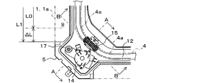
- FIG. 7 is a plan view showing the installation position of the antibacterial unit 15 in the present embodiment.
- the antibacterial unit 15 is disposed immediately below the heat exchanger 4 (see also FIG. 3).
- almost the entire antibacterial unit 15 is disposed immediately below the heat exchanger 4, but a part of the antibacterial unit 15 may be disposed immediately below the heat exchanger 4.
- the antibacterial unit 15 is installed in the opening groove portion 13 of the partition wall 12 in the drain pan 5.
- the opening groove portion 13 is formed to have a size corresponding to the size of the antibacterial unit 15 so that the antibacterial unit 15 is fitted into the opening groove portion 13.
- the circumferential dimension L1 of the air passage cross section in the present embodiment can ensure the same dimension as the dimension when the antibacterial unit 15 is not installed. That is, according to the present embodiment, it is not necessary to make ⁇ L shorter than the dimension L1 in the case where the antibacterial unit 15 is not installed as in the circumferential direction dimension L0 of the air passage cross section in the comparative example.
- the drain pump 14, the antibacterial unit 15, and the float switch 17 have the same corner of the drain pan 5 having a square frame shape in plan view, that is, a square shape in plan view. It is installed at the same one of four corners in the housing 1a.
- the heat exchanger 4 has two bent portions 4a at one corner in the housing 1a, specifically at the corner where the drain pump 14 is installed.
- the antimicrobial unit 15 is arrange
- the antibacterial unit 15 is installed such that the longitudinal direction of the antibacterial unit 15 in plan view is along the extending direction of the heat exchanger 4 in plan view.
- FIG. 8 is a cross-sectional view taken along the line AA of FIG.
- FIG. 9 is a cross-sectional view taken along the line BB in FIG.
- the bottom surface of the opening groove portion 13 is located on the bottom surface of the primary space (the space located upstream of the heat exchanger 4) of the drain pan 5 and the secondary space (downstream of the heat exchanger 4). It is set to the same height as the bottom of the space) side.
- the partition wall 12 has a function to prevent the air 21 (see FIG. 2, the same applies hereinafter) to the secondary side (downstream side) of the heat exchanger 4 without passing through the heat exchanger 4. .
- a resistor 30 of air is provided to fill the gap between the partition wall 12 and the heat exchanger 4.
- an air resistor 31 is provided on the antibacterial unit 15 so as to fill the gap between the antibacterial unit 15 and the heat exchanger 4 (and the resistor 30).
- materials of the resistors 30, 31 for example, materials such as foamed rubber may be used.
- the display of the resistors 30 and 31 is omitted for convenience of description.
- the indoor unit 100 of the air conditioner includes the heat exchanger 4 surrounding the discharge direction of the air from the blower fan 2, and the drain pan 5 disposed below the heat exchanger 4. And an antimicrobial unit 15 disposed on the drain pan 5 and having an antimicrobial agent that disinfects drain water, and at least a part of the antimicrobial unit 15 is disposed immediately below the heat exchanger 4.
- the indoor unit 100 of the air conditioner which installed the antibacterial agent on the drain pan 5 can be provided, suppressing the reduction of the cross-sectional area of the blowing air path 9. FIG. Therefore, the cross-sectional area of the outlet air passage is reduced, and the increase in noise and the increase in fan power are not caused.
- the antibacterial unit 15 is installed in the opening groove portion 13 of the partition wall 12 in the drain pan 5.
- the antibacterial unit 15 can be efficiently installed on the drain pan 5.
- the antibacterial unit 15 is installed in the opening groove part 13 used as the part which the drain water which flows on drain pan 5 passes or merges, it becomes possible to fully exhibit the antibacterial effect by the antibacterial unit 15.
- the drain pump 14, the antibacterial unit 15, and the float switch 17 are installed at the same corner in the housing 1a. Therefore, the antimicrobial unit 15 can be installed in a narrow space near the drain pump 14 or the float switch 17 on the drain pan 5. Further, since the drain water is collected toward the drain pump 14, the drain water around the drain pump 14 can be efficiently antibacterially prevented, and the generation of slime can be more effectively prevented.
- the bottom surface of the opening groove 13 since the bottom surface of the opening groove 13, the bottom surface on the primary space side of the drain pan 5 and the bottom surface on the secondary space side have the same depth, the flow of drain water is not hindered . Thereby, it can suppress that drain water stagnates and bacteria reproduces.
- the antibacterial unit 15 is arrange
- the longitudinal direction of the antibacterial unit 15 in plan view is generally along the extending direction of the heat exchanger 4 in plan view. For this reason, it is possible to position most of the antibacterial unit 15 immediately below the heat exchanger 4, and it is possible to further suppress the reduction in the cross-sectional area of the blowoff air passage 9.
- the resistor 31 of air is disposed on the antibacterial unit 15.
- the gap between the antibacterial unit 15 and the heat exchanger 4 in the opening groove portion 13 of the partition wall 12 is filled with the resistor 31, only drain water can be passed without passing the air 21. It becomes.
- the air 21 when there is drain water up to the height of the antibacterial unit 15 during the cooling operation of the indoor unit 100, it is possible to prevent the air 21 from leaking to the secondary side of the heat exchanger 4.
- FIG. 10 is a view for explaining a modification of the present embodiment.
- the antimicrobial unit 15 is installed in the opening groove part 13 of the partition wall 12 in the drain pan 5, this invention is not limited to this.
- the drain pan 5a may have a step composed of a first bottom surface 12a and a second bottom surface 12b lower than the first bottom surface 12a.
- a recess 13a may be formed in a portion of the first bottom surface 12a located below the heat exchanger 4, and the antibacterial unit 15 may be installed in the recess 13a.
Landscapes
- Engineering & Computer Science (AREA)
- Mechanical Engineering (AREA)
- Chemical & Material Sciences (AREA)
- Combustion & Propulsion (AREA)
- General Engineering & Computer Science (AREA)
- Physics & Mathematics (AREA)
- Thermal Sciences (AREA)
- Ceramic Engineering (AREA)
- Devices For Blowing Cold Air, Devices For Blowing Warm Air, And Means For Preventing Water Condensation In Air Conditioning Units (AREA)
Abstract
空気調和機の室内機は、送風ファンからの空気の吐出方向を囲う熱交換器(4)と、熱交換器(4)の下方に配置されるドレンパン(5)と、ドレンパン(5)上に設置され、ドレン水を抗菌する抗菌剤を有する抗菌ユニット(15)と、を備えている。そして、抗菌ユニット(15)の少なくとも一部が、熱交換器(4)の直下に配置されている。これにより、吹出風路の断面積の減少を抑制しつつ、抗菌剤をドレンパン(5)上に設置した空気調和機の室内機を提供する。
Description
本発明は、空気調和機の室内機に関し、特に、天井埋込み型の空気調和機の室内機に関する。
空気調和機の室内機として、室内機が天井に埋め込まれるタイプ(天井埋込み型)のものがある。天井埋込み型の空気調和機の室内機は、遠心ファンを回転させることによって、室内の空気を吸い込み、吸込んだ空気を熱交換器で冷却して、吹出口から吹き出すことで室内を冷房する。
このような空気調和機の室内機では、冷房運転時に、熱交換器においてドレン水が発生し、ドレン水はドレンパンに溜まり、ドレンポンプにて室内機の外に排出される。しかし、ドレンポンプはその吸出限度高さよりも下にあるドレン水を排出することができないため、運転停止後には必ず一定量のドレン水がドレンパンに残留する。この残留したドレン水に細菌が繁殖し、ドロドロのスライムが発生して、ドレンポンプを詰まらせる不具合が発生することがある。
かかる不具合を防止するために、ドレンパンの内側に抗菌剤を設置する対策が一般に行われている。
従来では、例えば、液体の抗菌剤をドレンパンの内面に塗ったり、ドレンパンの表面における樹脂のドレンパンシートに抗菌剤を練り込んだりして、抗菌剤が少しずつドレン水に溶け出すようにした方策がある。しかし、この方策では、比較的早く抗菌効果が弱くなってしまうので、抗菌効果を持続させるためにドレンパン自体を交換しなければならなかった。
そこで、最近では、固形の抗菌剤をケースに入れてドレンパンの底面に設置することが一般に行われている(特許文献1、2参照)。
従来では、例えば、液体の抗菌剤をドレンパンの内面に塗ったり、ドレンパンの表面における樹脂のドレンパンシートに抗菌剤を練り込んだりして、抗菌剤が少しずつドレン水に溶け出すようにした方策がある。しかし、この方策では、比較的早く抗菌効果が弱くなってしまうので、抗菌効果を持続させるためにドレンパン自体を交換しなければならなかった。
そこで、最近では、固形の抗菌剤をケースに入れてドレンパンの底面に設置することが一般に行われている(特許文献1、2参照)。
抗菌剤は、ドレン水を効率良く抗菌するために、ドレンパンにおけるドレン水が集まるドレンポンプの近くに設置されることが多い。また、ドレンポンプの近くには、ドレン水のドレンパンからのオーバーフローを防止するためのフロートスイッチが設置されている。したがって、ドレンパン上のこのような各種部品が設置される箇所に、抗菌剤を設置するスペースが新たに必要となる。
しかしながら、ドレンパン上のドレンポンプ付近に抗菌剤の設置スペースを設けるためにドレンパンを広げる(大きくする)ことは、ドレンパンと本体ケースとの間に形成される冷却空気の吹出風路の断面積を小さくすることになる。このため、騒音の増加や、ファン動力の増加を招いてしまう。特に、小型の室内機では、標準の室内機と同じドレンポンプ、フロートスイッチ、および抗菌剤が一般に利用されるため、これらの部品が占めるスペースのドレンパン全体に対する割合が大きくなり、吹出風路の断面積の減少度合いが一層大きくなる。
本発明は、前記した事情に鑑みてなされたものであり、吹出風路の断面積の減少を抑制しつつ、抗菌剤をドレンパン上に設置した空気調和機の室内機を提供することを課題とする。
上記課題を解決するために、本発明に係る空気調和機の室内機は、筐体内に設けられる送風ファンと、前記送風ファンからの空気の吐出方向を囲う熱交換器と、前記熱交換器の下方に配置されるドレンパンと、前記ドレンパン上に設置され、ドレン水を抗菌する抗菌剤を有する抗菌ユニットと、を備え、前記抗菌ユニットの少なくとも一部が、前記熱交換器の直下に配置される。
本発明によれば、吹出風路の断面積の減少を抑制しつつ、抗菌剤をドレンパン上に設置した空気調和機の室内機を提供することができる。
本発明の実施形態について、適宜図面を参照しながら詳細に説明する。
なお、以下に示す図面において、同一の部材には同一の参照符号を付している。
なお、以下に示す図面において、同一の部材には同一の参照符号を付している。
図1は、本発明の一実施形態に係る空気調和機の室内機(以下、単に「室内機」ともいう)100の半断面図である。図2は、図1に示される室内機100における空気の流れを説明するための断面斜視図である。図2は、化粧パネル42(図1参照)が取り外された状態を示している。
図1に示すように、本実施形態に係る室内機100は、天井41に埋め込まれるタイプ(天井埋込み型)の室内機である。本実施形態における空気調和装置は、室内機100と室外機(図示せず)とが冷媒配管(図示せず)によって接続されて冷凍サイクルを構成し、空気調和を行う。
室内機100は、本体ケース1と化粧パネル42とを有している。化粧パネル42の下面が室内に臨んでおり、本体ケース1が天井41の内部に埋め込まれて配置される。化粧パネル42は、天井41の表面とほぼ面一となるように、本体ケース1の下方に取り付けられる。本体ケース1は天井裏(天井41の表面よりも上)に吊金具と吊ボルト(図示せず)を用いて据え付けられ固定される。化粧パネル42は、本体ケース1にネジ部材(図示せず)などを使用して固定される。
本体ケース1は、筐体1aと断熱材1bとを備えている。筐体1aは、平面視して四角形状を呈しており、金属板を用いて下方に開口をもつ有底箱状に形成されている。ここで「四角形状」というのは「厳密な四角形状」のほか、例えば角部が面取りされたり丸くされたりした「略四角形状」をも含む概念である。筐体1aは、2枚以上の板金がプレスで所定形状に成形され、ネジ止め、リベットなどで接合されて形成される。本体ケース1には、断熱や結露防止、防音などのための断熱材1bが、筐体1aの内部に開口を下に向けて配置されている。
室内機100は、筐体1a内に設けられる送風ファン2と、送風ファン2からの空気の吐出方向を囲う熱交換器4と、熱交換器4の下方に配置されるドレンパン5と、を備えている。送風ファン2は、例えば遠心ファンであり、空気の流れの向きを略90度変えて熱交換器4に送る。送風ファン2は、筐体1a内に設けられるファンモータ3によって回転駆動される。ファンモータ3は、筐体1aの天板に固定されている。送風ファン2とファンモータ3とで送風機が構成されている。
ドレンパン5は、熱交換器4の表面で結露して滴下するドレン水を受けて回収する。ドレンパン5は、例えば発泡スチロール成形品であり、ドレン水が接する内面側に例えばABS樹脂などの樹脂からなる樹脂層が形成されている。
室内機100の下面中央には、空気の吸込口6が設けられている。また、室内機100の下面周縁には、空気の吹出口7(ここでは4箇所)が設けられている。送風ファン2は、吸込口6と吹出口7とを結ぶ筐体1a内の空気通路に設けられる。熱交換器4は、送風ファン2と吹出口7との間に配置される。そして、送風ファン2と吸込口6との間には、ベルマウス8が設けられている。
図2に示すように、室内の空気21は、送風ファン2の回転動作により、吸込口6(図1参照)から吸い込まれ、送風ファン2を抜けて熱交換器4に向けて吹き出される。冷房運転の場合には、熱交換器4を通過することによって空気21は冷却される。熱交換器4を抜けて冷却された空気21は、ドレンパン5と、本体ケース1の断熱材1bとの間に形成される吹出風路9を通り、吹出口7(図1参照)を経て、室内機100から室内へ吹き出される。
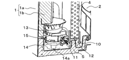
図3は、図1に示される室内機100のドレンポンプ14周辺を示す断面斜視図である。図4は、ドレンパン5上における抗菌ユニット15の設置状態を説明するための斜視図である。図5は、ドレンパン5上における抗菌ユニット15の設置状態を説明するための平面図である。図4では、説明の都合上、熱交換器4の表示を省略している。
図3~図4に示すように、ドレンパン5は、該ドレンパン5上における熱交換器4の空気21(図2参照、以下同様)の流れの上流側(一次側)に位置する一次空間と下流側(二次側)に位置する二次空間とを仕切る仕切壁12を有している。また、仕切壁12には、前記一次空間と前記二次空間とを連通させるように一部が切り欠かれた開口溝部13が形成されている。
室内の空気21が熱交換器4によって除湿されると、ドレン水が発生する。ドレン水は、ドレンパン5上における一次空間に流れ落ちるドレン水10と、ドレンパン5上における二次空間に流れ落ちるドレン水11とに分かれる。
室内機100(図1参照、以下同様)は、ドレンパン5に溜まるドレン水を排出するドレンポンプ14を備えている。ドレンパン5上における一次空間に流れ落ちるドレン水10は、仕切壁12の開口溝部13を通ってドレンポンプ14の方に導かれる。ドレン水10とドレン水11とは、仕切壁12の開口溝部13付近で合流し、ドレンポンプ14で吸い上げられて、機外へ排出される。ドレンポンプ14は、その吸出限度高さよりも下のドレン水を排出することができないため、空気調和機の運転停止後には、必ず一定量のドレン水がドレンパン5に残留する。この残留したドレン水に細菌が繁殖し、ドロドロのスライムが発生し、ドレンポンプ14を詰まらせる不具合が発生することがある。
これを防止するための方策として、ドレンパン5上には、ドレン水を抗菌する抗菌剤を有する抗菌ユニット15が設置されている。抗菌ユニット15は、固形の抗菌剤を樹脂製のケース内に収容して構成されている。ケースの壁部には、ドレン水をケース内に通過可能にする複数の通孔が形成されている。抗菌ユニット15は、例えばネジ部材16を用いて、ドレンパン5上に固定されている。
抗菌ユニット15は、ドレンパン5上におけるドレンポンプ14の近くに設置されることが好ましい。ドレンポンプ14の吸出口14aに対向する位置のドレンパン5の底面は、周辺部と比較してより低く形成されており、ドレンポンプ14に向けてドレン水が集まるようになっているからである。
図5に示すように、ドレンパン5は、平面視して四角枠形状を呈している。ここで「四角枠形状」というのは「厳密な四角枠形状」のほか、例えば角部が外側に拡張されたり面取りされたりした「略四角枠形状」をも含む概念である。ドレンポンプ14は、フロートスイッチ17とともに、ドレンパン5の角部に設置されるのが一般的である。
送風ファン2の回転軸心の半径方向においてドレンパン5と本体ケース1の断熱材1b(図2参照)との間に形成される吹出風路9は、周方向においては、四角枠形状を呈するドレンパン5の隣り合う角部同士の間に形成されている。吹出風路9は、ここでは4箇所形成されている。図5に示す符号L1~L4は、各吹出風路9における空気の流れ方向に垂直な断面の周方向の長さ(以下、「風路断面の周方向寸法)ともいう)を示している。
フロートスイッチ17は、ドレンパン5に溜まるドレン水が所定量以上となったことを検知する。フロートスイッチ17によってドレンパン5に溜まるドレン水が所定量以上となったことが検知されると、空気調和機の運転が停止される。これにより、ドレン水のドレンパン5からのオーバーフローを防止できるようになっている。
ところで、特に小型の天井埋込み型の空気調和機の室内機100では、ドレンパン5の角部における部品の設置スペースが狭小となっており、ドレンポンプ14とフロートスイッチ17と抗菌ユニット15とをドレンパン5の同じ角部に配置するのは難しい。
図6は、比較例としての抗菌ユニット15の設置位置を示す平面図である。図6に示す比較例は、ドレンパン5の角部の設置スペースを広げた(大きくした)例である。しかし、この比較例では、風路断面の周方向寸法L0は、ドレンパン5の角部の設置スペースを広げた分だけ短くなる。このため、吹出風路9の断面積が減少することになり、騒音の増加や、ファン動力の増加を引き起こすおそれがある。
ドレン水の発生量は、ドレン水11(図3参照)よりもドレン水10(図3参照)の方が多い。これは、熱交換器4においては一次側(空気の流れの上流側)から1列目の冷媒配管付近が最も熱交換量が高いためである。図6に示すように、ドレンポンプ14に向けて集まるドレン水10、11(図3参照)は、4つの経路にそれぞれ沿うドレン水10a、10b、11a、11bとなって流れる。しかし、図6に示す比較例では、ドレン水10a、10b、11bが抗菌ユニット15から遠い所を流れるために、抗菌ユニット15による抗菌がしにくくなり、抗菌効果が十分に発揮できないおそれがある。
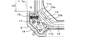
図7は、本実施形態における抗菌ユニット15の設置位置を示す平面図である。
図7に示すように、本実施形態では、抗菌ユニット15は、熱交換器4の直下に配置される(図3も参照)。ここでは、抗菌ユニット15の殆ど全体が熱交換器4の直下に配置されているが、抗菌ユニット15の一部が熱交換器4の直下に配置される構成であってもよい。
図7に示すように、本実施形態では、抗菌ユニット15は、熱交換器4の直下に配置される(図3も参照)。ここでは、抗菌ユニット15の殆ど全体が熱交換器4の直下に配置されているが、抗菌ユニット15の一部が熱交換器4の直下に配置される構成であってもよい。
具体的には、抗菌ユニット15は、ドレンパン5における仕切壁12の開口溝部13に設置されている。開口溝部13は、抗菌ユニット15の大きさに対応した大きさに形成されており、抗菌ユニット15が開口溝部13内に嵌着されるようになっている。これにより、本実施形態における風路断面の周方向寸法L1は、抗菌ユニット15を設置しない場合の寸法と同じ寸法を確保することができる。つまり、本実施形態によれば、比較例における風路断面の周方向寸法L0のように抗菌ユニット15を設置しない場合の寸法L1よりもΔL短くする必要がない。
図5、図7に示すように、ドレンポンプ14と抗菌ユニット15とフロートスイッチ17とは、平面視して四角枠形状を呈するドレンパン5の同じ角部、すなわち、平面視して四角形状を呈する筐体1a内の四つの隅部のうちの同じ一つの隅部に設置されている。
熱交換器4は、筐体1a内の一の隅部、具体的にはドレンポンプ14が設置される隅部において2箇所の屈曲部4aを有している。そして、抗菌ユニット15は、平面視して前記2箇所の屈曲部4a、4aの間に配置されている。また、抗菌ユニット15は、抗菌ユニット15の平面視した長手方向が、熱交換器4の平面視した延在方向に沿うように設置されている。
図8は、図7のA-A線に沿う断面図である。図9は、図7のB-B線に沿う断面図である。
図8に示すように、開口溝部13の底面は、ドレンパン5の一次空間(熱交換器4の上流側に位置する空間)側の底面および二次空間(熱交換器4の下流側に位置する空間)側の底面と同一の高さに設定されている。
図8に示すように、開口溝部13の底面は、ドレンパン5の一次空間(熱交換器4の上流側に位置する空間)側の底面および二次空間(熱交換器4の下流側に位置する空間)側の底面と同一の高さに設定されている。
仕切壁12は、空気21(図2参照、以下同様)が熱交換器4を通らないで熱交換器4の二次側(下流側)へ抜けてしまうのを防止する機能を有している。そして、仕切壁12の上に、該仕切壁12と熱交換器4との間の隙間を埋める空気の抵抗体30が設置されている。また、仕切壁12の開口溝部13は、空気21が通らず、ドレン水のみを通すことが望ましい。このため、図9に示すように、抗菌ユニット15の上に、該抗菌ユニット15と熱交換器4(および抵抗体30)との間の隙間を埋める空気の抵抗体31が設置されている。抵抗体30、31の材料としては、例えば発泡ゴムなどの材料が使用され得る。なお、図1などの他の図では、説明の都合上、抵抗体30、31の表示を省略している。
前記したように、本実施形態に係る空気調和機の室内機100は、送風ファン2からの空気の吐出方向を囲う熱交換器4と、熱交換器4の下方に配置されるドレンパン5と、ドレンパン5上に設置され、ドレン水を抗菌する抗菌剤を有する抗菌ユニット15と、を備え、抗菌ユニット15の少なくとも一部が、熱交換器4の直下に配置されている。
このような本実施形態によれば、吹出風路9の断面積の減少を抑制しつつ、抗菌剤をドレンパン5上に設置した空気調和機の室内機100を提供することができる。したがって、吹出風路の断面積が小さくなって、騒音の増加や、ファン動力の増加を引き起こすこともなくなる。
また、本実施形態では、抗菌ユニット15は、ドレンパン5における仕切壁12の開口溝部13に設置されている。この構成では、ドレンパン5上の仕切壁12に抗菌ユニット15に対応した開口溝部13を形成することによって、抗菌ユニット15を効率良くドレンパン5上に設置することができる。また、ドレンパン5上を流れるドレン水が通過、あるいは合流する部分となる開口溝部13に抗菌ユニット15が設置されているため、抗菌ユニット15による抗菌効果を十分に発揮させることが可能となる。
また、本実施形態では、ドレンポンプ14と抗菌ユニット15とフロートスイッチ17とが筐体1a内の同じ隅部に設置されている。したがって、抗菌ユニット15をドレンパン5上におけるドレンポンプ14やフロートスイッチ17の近くの狭小なスペースに設置することができる。また、ドレンポンプ14に向けてドレン水が集まるようになっているため、ドレンポンプ14の周りのドレン水を効率良く抗菌してスライムの発生をより効果的に防止することができる。
また、本実施形態では、開口溝部13の底面と、ドレンパン5の一次空間側の底面および二次空間側の底面とが同一の深さとなっているため、ドレン水の流れが妨げられることがない。これにより、ドレン水が滞留して細菌が繁殖することを抑制できる。
また、本実施形態では、抗菌ユニット15は、筐体1a内の一の隅部における熱交換器4の2箇所の屈曲部4a、4aの間に配置されている。このため、筐体1a内の隅部にドレンポンプ14が設置されるスペースを確保できるとともに、抗菌ユニット15をドレンポンプ14の近くに効率良く配置することができる。
また、本実施形態では、抗菌ユニット15の平面視した長手方向が、熱交換器4の平面視した延在方向に概ね沿うようになっている。このため、抗菌ユニット15の大部分を熱交換器4の直下に位置させることができ、吹出風路9の断面積の減少をより抑制することが可能となる。
また、本実施形態では、抗菌ユニット15の上に空気の抵抗体31が設置されている。この構成では、仕切壁12の開口溝部13における抗菌ユニット15と熱交換器4との間の隙間は、抵抗体31によって埋められるため、空気21を通さずに、ドレン水のみを通すことが可能となる。また、室内機100の冷房運転時において抗菌ユニット15の高さまでドレン水がある場合には、空気21が熱交換器4の二次側へ抜けてしまうのを防ぐことができる。
以上、本発明について実施形態に基づいて説明したが、本発明は前記した実施形態に限定されるものではなく、様々な変形例が含まれる。例えば、前記した実施形態は本発明を分かりやすく説明するために詳細に説明したものであり、必ずしも説明した全ての構成を備えるものに限定されるものではない。また、実施形態の構成の一部について、他の構成の追加・削除・置換をすることが可能である。
図10は、本実施形態の変形例を説明するための図である。
前記した実施形態では、抗菌ユニット15は、ドレンパン5における仕切壁12の開口溝部13に設置されているが、本発明はこれに限定されるものではない。例えば図10に示すように、ドレンパン5aが、第1底面12aとこれよりも低い第2底面12bとから構成される段差を有していてもよい。この場合、第1底面12aにおける熱交換器4の下方に位置する部分に凹部13aを形成して、この凹部13aに抗菌ユニット15を設置するとよい。
前記した実施形態では、抗菌ユニット15は、ドレンパン5における仕切壁12の開口溝部13に設置されているが、本発明はこれに限定されるものではない。例えば図10に示すように、ドレンパン5aが、第1底面12aとこれよりも低い第2底面12bとから構成される段差を有していてもよい。この場合、第1底面12aにおける熱交換器4の下方に位置する部分に凹部13aを形成して、この凹部13aに抗菌ユニット15を設置するとよい。
1 本体ケース
1a 筐体
2 送風ファン
3 ファンモータ
4 熱交換器
4a 屈曲部
5、5a ドレンパン
6 吸込口
7 吹出口
8 ベルマウス
9 吹出風路
10、11 ドレン水
12 仕切壁
13 開口溝部
14 ドレンポンプ
15 抗菌ユニット
17 フロートスイッチ
21 空気
30、31 抵抗体
100 空気調和機の空調機
1a 筐体
2 送風ファン
3 ファンモータ
4 熱交換器
4a 屈曲部
5、5a ドレンパン
6 吸込口
7 吹出口
8 ベルマウス
9 吹出風路
10、11 ドレン水
12 仕切壁
13 開口溝部
14 ドレンポンプ
15 抗菌ユニット
17 フロートスイッチ
21 空気
30、31 抵抗体
100 空気調和機の空調機
Claims (7)
- 筐体内に設けられる送風ファンと、
前記送風ファンからの空気の吐出方向を囲う熱交換器と、
前記熱交換器の下方に配置されるドレンパンと、
前記ドレンパン上に設置され、ドレン水を抗菌する抗菌剤を有する抗菌ユニットと、を備え、
前記抗菌ユニットの少なくとも一部が、前記熱交換器の直下に配置されることを特徴とする空気調和機の室内機。 - 前記ドレンパンは、該ドレンパン上における前記熱交換器の上流側に位置する一次空間と下流側に位置する二次空間とを仕切る仕切壁を有し、
前記仕切壁には、前記一次空間と前記二次空間とを連通させるように一部が切り欠かれた開口溝部が形成されており、
前記抗菌ユニットは、前記仕切壁の前記開口溝部に設置されることを特徴とする請求項1に記載の空気調和機の室内機。 - 前記ドレンパンに溜まるドレン水を排出するドレンポンプを備え、
前記ドレンポンプと前記抗菌ユニットとは、平面視して四角形状を呈する前記筐体内の同じ隅部に設置されることを特徴とする請求項1または請求項2に記載の空気調和機の室内機。 - 前記開口溝部の底面は、前記ドレンパンの前記一次空間側の底面および前記二次空間側の底面と同一の高さに設定されていることを特徴とする請求項2に記載の空気調和機の室内機。
- 前記熱交換器は、平面視して四角形状を呈する前記筐体内の一の隅部において2箇所の屈曲部を有し、
前記抗菌ユニットは、平面視して前記2箇所の屈曲部の間に配置されることを特徴とする請求項1または請求項2に記載の空気調和機の室内機。 - 前記抗菌ユニットは、該抗菌ユニットの平面視した長手方向が前記熱交換器の平面視した延在方向に沿うように設置されることを特徴とする請求項1または請求項2に記載の空気調和機の室内機。
- 前記抗菌ユニットの上に、該抗菌ユニットと前記熱交換器との間の隙間を埋める空気の抵抗体が設置されることを特徴とする請求項1または請求項2に記載の空気調和機の室内機。
Priority Applications (5)
| Application Number | Priority Date | Filing Date | Title |
|---|---|---|---|
| EP15897728.0A EP3321602B1 (en) | 2015-07-08 | 2015-07-08 | Indoor unit for air conditioner |
| CN201580081572.XA CN107850337A (zh) | 2015-07-08 | 2015-07-08 | 空气调节机的室内机 |
| PCT/JP2015/069687 WO2017006466A1 (ja) | 2015-07-08 | 2015-07-08 | 空気調和機の室内機 |
| JP2017527041A JP6488011B2 (ja) | 2015-07-08 | 2015-07-08 | 空気調和機の室内機 |
| US15/740,157 US20180195790A1 (en) | 2015-07-08 | 2015-07-08 | Indoor unit for air conditioner |
Applications Claiming Priority (1)
| Application Number | Priority Date | Filing Date | Title |
|---|---|---|---|
| PCT/JP2015/069687 WO2017006466A1 (ja) | 2015-07-08 | 2015-07-08 | 空気調和機の室内機 |
Publications (1)
| Publication Number | Publication Date |
|---|---|
| WO2017006466A1 true WO2017006466A1 (ja) | 2017-01-12 |
Family
ID=57685231
Family Applications (1)
| Application Number | Title | Priority Date | Filing Date |
|---|---|---|---|
| PCT/JP2015/069687 Ceased WO2017006466A1 (ja) | 2015-07-08 | 2015-07-08 | 空気調和機の室内機 |
Country Status (5)
| Country | Link |
|---|---|
| US (1) | US20180195790A1 (ja) |
| EP (1) | EP3321602B1 (ja) |
| JP (1) | JP6488011B2 (ja) |
| CN (1) | CN107850337A (ja) |
| WO (1) | WO2017006466A1 (ja) |
Cited By (4)
| Publication number | Priority date | Publication date | Assignee | Title |
|---|---|---|---|---|
| JP2019086240A (ja) * | 2017-11-08 | 2019-06-06 | 三菱電機株式会社 | 空気調和機 |
| JP2019124422A (ja) * | 2018-01-18 | 2019-07-25 | 三菱重工サーマルシステムズ株式会社 | 天井埋込み型空気調和機 |
| JP2019148354A (ja) * | 2018-02-26 | 2019-09-05 | パナソニックIpマネジメント株式会社 | 天井埋込型室内ユニット |
| JP2023049970A (ja) * | 2021-09-29 | 2023-04-10 | パナソニックIpマネジメント株式会社 | 室内ユニット |
Families Citing this family (5)
| Publication number | Priority date | Publication date | Assignee | Title |
|---|---|---|---|---|
| US10514196B2 (en) * | 2017-01-18 | 2019-12-24 | Carrier Corporation | Condensate drain pan port |
| US12123614B2 (en) * | 2019-10-31 | 2024-10-22 | Qingdao Hisense Hitachi Air-conditioning Systems Co., Ltd. | Ducted air conditioner and assembling method thereof |
| CN114646097B (zh) * | 2022-04-18 | 2025-09-19 | 珠海格力电器股份有限公司 | 换热器组件以及具有的空调器 |
| JP2025177807A (ja) * | 2024-05-24 | 2025-12-05 | 日本キヤリア株式会社 | 空気調和機の室内機 |
| EP4671629A1 (en) * | 2024-05-24 | 2025-12-31 | Carrier Japan Corporation | INDOOR AIR CONDITIONER UNIT |
Citations (4)
| Publication number | Priority date | Publication date | Assignee | Title |
|---|---|---|---|---|
| JP2007240113A (ja) * | 2006-03-10 | 2007-09-20 | Daikin Ind Ltd | 空気調和機 |
| JP2010065931A (ja) * | 2008-09-11 | 2010-03-25 | Mitsubishi Heavy Ind Ltd | 空気調和装置 |
| JP2011012850A (ja) * | 2009-06-30 | 2011-01-20 | Daikin Industries Ltd | 空気調和機 |
| JP2013076518A (ja) * | 2011-09-30 | 2013-04-25 | Mitsubishi Electric Corp | 空気調和機 |
Family Cites Families (3)
| Publication number | Priority date | Publication date | Assignee | Title |
|---|---|---|---|---|
| JP4252530B2 (ja) * | 2004-12-13 | 2009-04-08 | ダイキン工業株式会社 | 空気調和機のドレン水静菌構造 |
| JP4585377B2 (ja) * | 2005-06-02 | 2010-11-24 | 東芝キヤリア株式会社 | 空気調和装置 |
| CN101078557A (zh) * | 2006-05-25 | 2007-11-28 | 乐金电子(天津)电器有限公司 | 空调器室内机的排水盘 |
-
2015
- 2015-07-08 CN CN201580081572.XA patent/CN107850337A/zh active Pending
- 2015-07-08 JP JP2017527041A patent/JP6488011B2/ja active Active
- 2015-07-08 EP EP15897728.0A patent/EP3321602B1/en active Active
- 2015-07-08 WO PCT/JP2015/069687 patent/WO2017006466A1/ja not_active Ceased
- 2015-07-08 US US15/740,157 patent/US20180195790A1/en not_active Abandoned
Patent Citations (4)
| Publication number | Priority date | Publication date | Assignee | Title |
|---|---|---|---|---|
| JP2007240113A (ja) * | 2006-03-10 | 2007-09-20 | Daikin Ind Ltd | 空気調和機 |
| JP2010065931A (ja) * | 2008-09-11 | 2010-03-25 | Mitsubishi Heavy Ind Ltd | 空気調和装置 |
| JP2011012850A (ja) * | 2009-06-30 | 2011-01-20 | Daikin Industries Ltd | 空気調和機 |
| JP2013076518A (ja) * | 2011-09-30 | 2013-04-25 | Mitsubishi Electric Corp | 空気調和機 |
Cited By (8)
| Publication number | Priority date | Publication date | Assignee | Title |
|---|---|---|---|---|
| JP2019086240A (ja) * | 2017-11-08 | 2019-06-06 | 三菱電機株式会社 | 空気調和機 |
| JP7031236B2 (ja) | 2017-11-08 | 2022-03-08 | 三菱電機株式会社 | 空気調和機 |
| JP2019124422A (ja) * | 2018-01-18 | 2019-07-25 | 三菱重工サーマルシステムズ株式会社 | 天井埋込み型空気調和機 |
| JP7086615B2 (ja) | 2018-01-18 | 2022-06-20 | 三菱重工サーマルシステムズ株式会社 | 天井埋込み型空気調和機 |
| JP2019148354A (ja) * | 2018-02-26 | 2019-09-05 | パナソニックIpマネジメント株式会社 | 天井埋込型室内ユニット |
| JP7213475B2 (ja) | 2018-02-26 | 2023-01-27 | パナソニックIpマネジメント株式会社 | 天井埋込型室内ユニット |
| JP2023049970A (ja) * | 2021-09-29 | 2023-04-10 | パナソニックIpマネジメント株式会社 | 室内ユニット |
| JP7696105B2 (ja) | 2021-09-29 | 2025-06-20 | パナソニックIpマネジメント株式会社 | 室内ユニット |
Also Published As
| Publication number | Publication date |
|---|---|
| JP6488011B2 (ja) | 2019-03-20 |
| EP3321602A4 (en) | 2019-02-27 |
| US20180195790A1 (en) | 2018-07-12 |
| EP3321602A1 (en) | 2018-05-16 |
| CN107850337A (zh) | 2018-03-27 |
| EP3321602B1 (en) | 2021-05-26 |
| JPWO2017006466A1 (ja) | 2018-03-22 |
Similar Documents
| Publication | Publication Date | Title |
|---|---|---|
| JP6488011B2 (ja) | 空気調和機の室内機 | |
| JP2009270778A (ja) | 空気調和機 | |
| JPWO2015025342A1 (ja) | 空気調和装置の室内機 | |
| JP6498291B2 (ja) | 空気調和機の室内機 | |
| JP2015081692A (ja) | 空気調和機の室内機 | |
| JP2014005954A (ja) | 空気調和装置の室内機 | |
| JP6579517B2 (ja) | 天井埋込型室内ユニット | |
| WO2016084216A1 (ja) | 空気調和機の室内機 | |
| JP5860752B2 (ja) | 空気調和機 | |
| JP2023108474A (ja) | 室内機 | |
| EP1515095B1 (en) | Indoor unit for air conditioner | |
| JP2006336948A (ja) | 空気調和装置 | |
| JP2017053559A (ja) | 空気調和機の室内機 | |
| JPWO2018123111A1 (ja) | 空調装置 | |
| JP2013249994A (ja) | 天井埋込ダクト型室内ユニット | |
| JP5305782B2 (ja) | 空気調和機 | |
| JP6976072B2 (ja) | 空気調和機の室内機 | |
| JP2010117104A (ja) | 空調機 | |
| JP2008045780A (ja) | 空気調和装置の室内ユニット | |
| JP6020084B2 (ja) | 車両用空調装置 | |
| JP2013092304A (ja) | 空気調和機の室内機 | |
| JP2007263430A (ja) | 空気調和機 | |
| JP2010048470A (ja) | 空気調和機 | |
| JP6340694B2 (ja) | 送風装置 | |
| JP6583783B2 (ja) | 天井埋込型室内ユニット |
Legal Events
| Date | Code | Title | Description |
|---|---|---|---|
| 121 | Ep: the epo has been informed by wipo that ep was designated in this application |
Ref document number: 15897728 Country of ref document: EP Kind code of ref document: A1 |
|
| ENP | Entry into the national phase |
Ref document number: 2017527041 Country of ref document: JP Kind code of ref document: A |
|
| NENP | Non-entry into the national phase |
Ref country code: DE |
|
| WWE | Wipo information: entry into national phase |
Ref document number: 2015897728 Country of ref document: EP |