WO2017006903A1 - 水洗大便器 - Google Patents
水洗大便器 Download PDFInfo
- Publication number
- WO2017006903A1 WO2017006903A1 PCT/JP2016/069766 JP2016069766W WO2017006903A1 WO 2017006903 A1 WO2017006903 A1 WO 2017006903A1 JP 2016069766 W JP2016069766 W JP 2016069766W WO 2017006903 A1 WO2017006903 A1 WO 2017006903A1
- Authority
- WO
- WIPO (PCT)
- Prior art keywords
- water
- water discharge
- rim
- toilet bowl
- discharge port
- Prior art date
- Legal status (The legal status is an assumption and is not a legal conclusion. Google has not performed a legal analysis and makes no representation as to the accuracy of the status listed.)
- Ceased
Links
Images









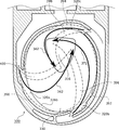
Classifications
-
- E—FIXED CONSTRUCTIONS
- E03—WATER SUPPLY; SEWERAGE
- E03D—WATER-CLOSETS OR URINALS WITH FLUSHING DEVICES; FLUSHING VALVES THEREFOR
- E03D11/00—Other component parts of water-closets, e.g. noise-reducing means in the flushing system, flushing pipes mounted in the bowl, seals for the bowl outlet, devices preventing overflow of the bowl contents; devices forming a water seal in the bowl after flushing, devices eliminating obstructions in the bowl outlet or preventing backflow of water and excrements from the waterpipe
- E03D11/02—Water-closet bowls ; Bowls with a double odour seal optionally with provisions for a good siphonic action; siphons as part of the bowl
- E03D11/08—Bowls with means producing a flushing water swirl
-
- E—FIXED CONSTRUCTIONS
- E03—WATER SUPPLY; SEWERAGE
- E03D—WATER-CLOSETS OR URINALS WITH FLUSHING DEVICES; FLUSHING VALVES THEREFOR
- E03D2201/00—Details and methods of use for water closets and urinals not otherwise provided for
- E03D2201/40—Devices for distribution of flush water inside the bowl
Definitions
- the present invention relates to a flush toilet.
- Patent Document 1 proposes a toilet cleaning device in which three water outlets are provided at the rear of the toilet bowl, and the discharge mode of the wash water discharged from the three water outlets can be changed by a switching valve.
- the discharge mode of the washing water a discharge mode using only one of the three water discharge ports and a mode using two water discharge ports in combination are disclosed.
- JP 2006-9382 A Japanese Patent No. 5553188 Japanese Patent Laying-Open No. 2015-67954
- the toilet bowl usually has a receiving surface for receiving filth and a rim connected to the upper edge of the receiving surface.
- a cleaning method of this toilet bowl there is a method of cleaning the toilet bowl by discharging the cleaning water from the water outlet formed in the rim to one side in the circumferential direction along the inner peripheral surface of the rim. known.
- this cleaning method a wider range in the stool portion including the inner peripheral surface of the rim portion can be cleaned with the cleaning water than a method of cleaning the stool portion by discharging the cleaning water downward from the water outlet of the rim portion. There is an advantage that good cleanliness can be obtained.
- the 1st invention is made in view of such a subject, and the object is to provide the flush toilet which can acquire the good rim washing ability.
- Patent Document 1 includes a concave portion formed below a bowl-shaped filth receiving surface, a rim portion, and two water discharge portions, and the main flow of cleaning water discharged from the two water discharge portions flows into the concave portion.
- a flush toilet is disclosed.
- flush toilets are required to be able to be washed with a smaller amount of water in order to effectively use water resources.
- FIG. 11 of Patent Document 2 shows an inflow path of cleaning water from two rim water spouting portions.
- the main stream from these rim water spouting portions flows in a biased manner toward the front side and the right side in the recess in plan view of the toilet bowl. For this reason, it is thought that the cleaning power of the filth adhering to the back side and the left side in the recess is insufficient in the toilet front view.
- the downward flow mainly toward the trap entrance is mainly formed in the mainstream, it is difficult to form a downward flow in the left back area of the recess in front view of the toilet, and stagnant filth remains It is also possible to do.
- when washing is performed with a small amount of water there is a concern that the influence of the deviation of the water flow in the recess and the downward flow becomes significant.
- the second invention is made in view of such a problem, and an object thereof is to provide a flush toilet capable of obtaining a good recess cleaning ability by suppressing the deviation of the water flow and the downward flow in the recess. .
- the flush toilet comprises a toilet bowl body having a toilet bowl portion and a water discharge section for discharging the wash water into the toilet bowl portion, and the toilet bowl portion has a receiving surface portion for receiving filth and an upper edge portion of the receiving surface portion.
- a rim portion connected to the rim portion, the water discharge portion has three water discharge ports formed in the rim portion, and from the three water discharge ports to one side in the circumferential direction along the inner peripheral surface of the rim portion.
- a toilet part for discharging the wash water and the toilet bowl part has a left and right center line that bisects the left and right dimension of the outer surface part of the toilet body in plan view, and the front and rear dimensions of the inner part of the toilet bowl part It has four divided areas that are divided by a front-rear center line that bisects in the front-rear direction, and the three spouts are individually formed in each of the three divided areas among the four divided areas. According to this aspect, individual spouts are formed in each of the three divided areas among the four divided areas.
- the inner peripheral length of the rim part from each water outlet to the other water outlet adjacent to one side in the circumferential direction is set. Can be shortened. For this reason, it becomes easy to make cleaning water reach the whole inner peripheral surface of a rim
- the first aspect of the second invention for solving the above problem is a flush toilet.
- the flush toilet includes a toilet body having a toilet bowl.
- the toilet bowl portion includes a receiving surface portion for receiving filth, a rim portion connected to the upper edge portion of the receiving surface portion, and a recessed portion formed to be recessed downward from the lower edge portion of the receiving surface portion.
- the concave portion is partitioned by three standing walls including a left standing wall and a right standing wall corresponding to the left and right sides of the triangle whose bottom side is located behind the left and right sides in plan view, and a rear standing wall corresponding to the bottom side.
- the rim portion includes a first water outlet provided on the side of the concave portion, a second water outlet provided in front of the concave portion, and a third water outlet provided behind the concave portion in plan view. Two water outlets are provided, and the three water outlets discharge cleaning water in one circumferential direction along the rim portion.
- FIG. 2 is a sectional view taken along line AA in FIG. 1. It is a figure for demonstrating the left-right centerline of the toilet body of 1st Embodiment, and the front-back centerline of a toilet bowl part. It is a figure which shows how the washing water flows in the initial stage in the toilet bowl part which concerns on 1st Embodiment. It is a figure which shows how the wash water flows in the middle stage in the toilet bowl part which concerns on 1st Embodiment.
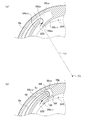
- FIG. 9 (a) is a figure which shows the toilet bowl main body which concerns on a 1st modification
- FIG.9 (b) is a figure which shows the toilet bowl main body which concerns on 1st Embodiment. . It is a figure for demonstrating the centrifugal force provided to washing water.
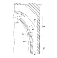
- FIG.11 (a) is a figure which shows the structure around the 2nd water discharge port which concerns on 1st Embodiment
- FIG.11 (b) is a figure which shows the structure around the 2nd water discharge port which concerns on a 2nd modification.
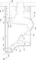
- It is a figure which shows the structure around the 3rd water discharge outlet of 1st Embodiment.
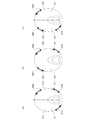
- It is a schematic diagram which shows the example of the arrangement pattern of the water outlet which can obtain an effect (2).
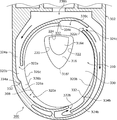
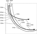
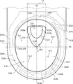
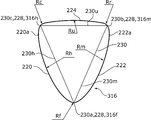
- 16 is a sectional view taken along line AA in FIG. It is a schematic diagram explaining the water flow around the turning part of 2nd Embodiment. It is a figure for demonstrating the central axis of the recessed part of 2nd Embodiment. It is a top view which expands and shows the inner edge of the recessed part of 2nd Embodiment. It is a figure which shows typically how the wash water flows in the toilet bowl part of 2nd Embodiment. It is a figure which shows typically the range through which the wash water flows in the toilet bowl part of 2nd Embodiment.
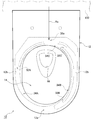
- FIG. 1 is a side sectional view of a flush toilet 10 according to the first embodiment
- FIG. 2 is a plan view of the flush toilet 10.
- the flush toilet 10 includes a toilet body 12 made of ceramic.
- the toilet body 12 is a wall-mounted toilet that is attached in a state of being hung on the side wall surface 100 of the toilet room.
- a box containing a hot water cleaning device such as a local cleaning device, a toilet lid and a toilet seat that are rotatably supported by the box are disposed above the toilet body 12.
- the toilet bowl body 12 has a toilet bowl portion through a toilet bowl portion 14 formed at the front portion of the toilet bowl body 12 and an entrance 16 (see also FIG. 2) formed at the bottom of the toilet bowl portion 14. 14 and a trap portion 18 communicating with the inside.
- the trap part 18 becomes a part of the drainage passage part 20 for discharging the filth in the toilet bowl part 14 to the sewer side water channel (not shown).
- the drainage passage portion 20 includes a connecting pipe 22 connected to the downstream end portion of the trap portion 18, and filth is discharged into the sewage side water channel through the inside thereof.
- the trap portion 18 stores a sealed water 24 that blocks the flow of air in the direction of water flow, and the backflow of odors from the sewage side water channel is prevented by the sealed water 24.
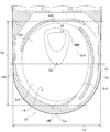
- FIG. 3 is a sectional view taken along line AA in FIG.
- the toilet bowl portion 14 is formed in an elliptical shape whose front and rear dimensions are larger than the left and right dimensions in plan view.
- the toilet bowl portion 14 includes a receiving surface portion 26 for receiving filth, a rim portion 28 that is connected to the upper edge portion of the receiving surface portion 26 and forms the upper edge portion of the toilet bowl portion 14, and a lower edge of the receiving surface portion 26. And a recess 30 formed to be recessed downward from the portion.
- the receiving surface portion 26 and the recessed portion 30 are provided continuously in an annular shape.
- the receiving surface portion 26 is formed so as to incline with a downward slope toward the ring center side.
- the recessed part 30 is formed in a bottomed shape, and the inlet 16 of the trap part 18 opens at the bottom. A part of the sealing water 24 is stored in the recess 30.
- the rim portion 28 has three rim conduits 34A to 34C formed so as to extend in the circumferential direction of the toilet bowl portion 14 from each of the three water outlets 32A to 32C.
- the water discharge ports 32A to 32C are collectively referred to as “water discharge port 32”
- the rim water conduits 34A to 34C are collectively referred to as “rim water conduit 34”.
- the rim water guide channel 34 is formed to guide the cleaning water discharged from the water discharge port 32 so as to turn.
- the rim conduit 34 has a shelf 34 a extending from the upper edge 26 a of the receiving surface 26 toward the outside of the toilet bowl 14, a standing wall 34 b rising from the outer peripheral end of the shelf 34 a, And an overhang portion 34c extending from the upper end portion of the standing wall portion 34b toward the inside of the toilet bowl portion 14.
- the radial dimension of the shelf 34 a is formed so as to become shorter from the spout 32 in the swirl flow turning direction Da (described later). The same applies to the overhang portion 34c.
- the wash water discharged from the water discharge port 32 gradually flows down to the receiving surface portion 26 as it leaves the water discharge port 32.
- the three rim conduits 34 include a first rim conduit 34A to a third rim conduit 34C corresponding to each of the three first outlets 32A to 32C.
- the first rim water conduit 34A is formed so as to extend in the swirl flow turning direction Da from the first water outlet 32A to the terminal position 34Aa with the end position 34Aa in the vicinity of the second water outlet 32B and the inner side in the plan view. Is done.
- the second rim conduit 34B is formed so as to extend in the swirl flow turning direction Da from the second water outlet 32B to the terminal position 34Ba, with the vicinity of the third water outlet 32C and the inside thereof as the terminal position 34Ba.
- the third rim conduit 34C is formed so as to extend from the third water outlet 32C to the terminal position 34Ca with the vicinity of the first water outlet 32A and the inside thereof as the terminal position 34Ca.
- Each of the rim conduits 34A to 34C is formed so as to extend over an angle range corresponding to at least 1/4 of an angular range around a center point Cp (described later) of the toilet bowl portion 14.
- FIG. 4 is a view for explaining the left-right center line La of the toilet body 12 and the front-rear center line Lb of the toilet bowl portion 14.
- the left-right center line La of the toilet main body 12 refers to a straight line extending in the front-rear direction by equally dividing the left-right dimension Lx of the outer surface portion of the toilet main body 12 in a plan view. Specifically, a straight line that bisects the left-right dimension Lx from the left end position 12L to the right end position 12R of the outer surface portion of the toilet body 12 is the left-right center line La.
- the front-rear center line Lb of the toilet bowl portion 14 bisects the front-rear dimension Ly of the inner surface portion of the toilet bowl portion 14 in a plan view of a horizontal section passing through the water discharge ports 32A to 32C of the toilet bowl portion 14.
- a straight line that bisects the front-rear dimension Ly from the front end position 14F to the rear end position 14R of the inner surface portion of the toilet bowl 14 is the front-rear center line Lb.
- the centerline Cp of the toilet bowl part 14 mentioned above refers to the intersection of the left-right centerline La and the front-rear centerline Lb.
- the toilet bowl 14 described above has four divided regions Sr1 to Sr4 that are divided by the left-right center line La and the front-rear center line Lb of the toilet bowl 14 in a plan view.
- a divided region on the rear side with respect to the front-rear center line Lb and on the right side with respect to the left-right center line La is referred to as a first divided region Sr1.
- the divided areas in the counterclockwise direction in plan view from the first divided area Sr1 are sequentially designated as a second divided area Sr2, a third divided area Sr3, and a fourth divided area Sr4.
- the second divided region Sr2 and the third divided region Sr3 are front divided regions
- the first divided region Sr1 and the fourth divided region Sr4 are rear divided regions.
- the toilet main body 12 further includes a water discharge section 36 having the three water discharge ports 32A to 32C described above.
- the water discharge unit 36 has a water flow unit 38 to be described later in addition to the three water discharge ports 32A to 32C.
- the water discharge portion 36 is for discharging wash water from the three water discharge ports 32A to 32C along the inner peripheral surface of the rim portion 28 in the swirl flow turning direction Da.
- the water discharger 36 discharges the wash water into the toilet bowl 14 from each of the water discharge ports 32A to 32C, thereby forming a swirling flow that swirls in the toilet bowl 14 in one direction.
- a swirl flow swirling around one side Da (counterclockwise direction) in the circumferential direction of the toilet bowl 14 is formed.
- one side Da in the circumferential direction is referred to as a swirl flow swirl direction Da.
- the three spouts 32A to 32C are individually formed in each of the three divided areas among the four divided areas Sr1 to Sr4 of the toilet bowl portion 14.
- the three water outlets 32A to 32C include a first water outlet 32A located in the first divided area Sr1, a second water outlet 32B located in the third divided area Sr3, and a position located in the fourth divided area Sr4. And a third water outlet 32C. Any of the water discharge ports 32A to 32C is formed so as to open in the swirl flow swirl direction Da.
- the water flow portion 38 is a hollow structure portion disposed on the back side of the rim portion 28 (outside in the radial direction of the toilet bowl portion 14).
- the water passing portion 38 communicates with each of the water discharge ports 32A to 32C and becomes a passage for the washing water supplied to each of the water discharge ports 32A to 32C.
- the water passage 38 includes an inflow passage 38a, a right water passage 38b (first water passage), and a left water passage 38c (second water passage).
- the inflow path 38 a is disposed behind and on the back side of the rim portion 28.
- the right-side water passage 38b is disposed on the back side of one right side portion 28R among the side portions on both the left and right sides of the rim portion 28.
- the left water passage 38c is disposed on the back side of the other left side portion 28L among the left and right side portions of the rim portion 28.
- the cleaning water supplied from the water supply pipe 102 which becomes a part of the cleaning water supply device flows into the inflow path 38a.
- 1 and 2 show a supply path Ra of the cleaning water from the water supply pipe 102 to the inflow path 38a.
- the cleaning water flows into the inflow path 38a through the introduction hole 38e formed in the rear wall 38d that is disposed behind the rim portion 28 and defines the inflow path 38a.
- the cleaning water supply device supplies cleaning water by a water supply direct pressure type water supply method using the tap water supply pressure.
- the inflow path 38 a is formed so as to expand in the left-right direction from the front of the introduction hole 38 e that becomes the inflow position Pa of the cleaning water from the cleaning water supply device.
- the right-hand water passage 38b communicates with one end of the inflow passage 38a in the left-right direction
- the left-hand water passage 38c communicates with the other end in the left-right direction.
- the right water passage 38b is formed on the back side of the right side portion 28R of the rim portion 28 so as to extend along the front-rear direction.
- a first water outlet 32A is formed at the downstream end of the right-side water passage 38b.
- the left water passage 38c includes a folded portion 38ca formed at the downstream end of the left water passage 38c, and a front / rear extending portion 38cb formed so as to communicate with the folded portion 38ca and extend in the front-rear direction. included.
- a second water discharge port 32B is formed at the downstream end of the folded portion 38ca that is the downstream end of the left water passage 38c.
- a branch portion 38cc is formed in the front-rear extending portion 38cb of the left water passage 38c so as to extend from the midway position in the front-rear direction to the swirl flow turning direction Da and radially inward.
- a third water discharge port 32 ⁇ / b> C is formed at the downstream end of the branch portion 38 cc, which is the midway position of the left water passage 38 c.
- the inner bottom surface 38cd in the range from the midway position of the front / rear extending portion 38cb to the branching portion 38cc is formed so as to rise as it approaches the third water discharge port 32C.
- the wash water supplied from the inflow passage 38a is guided to flow to the first water discharge port 32A (see direction Db).
- the front-rear extending portion 38cb of the left water passage 38c a part of the washing water supplied from the inflow passage 38a flows toward the folded portion 38ca (see direction Dc), and the remaining portion is guided toward the branch portion 38cc. It flows as it is (see direction Dd).
- the folded portion 38ca the washing water supplied from the upstream front / rear extending portion 38cb flows so as to be folded radially inward and guided to the second water discharge port 32B (see direction De).
- cleans the inside of the toilet bowl part 14 with the so-called washing-off type washing
- the operation members such as a switch and a lever for starting the supply of the cleaning water
- the cleaning water within a predetermined flow rate range is supplied from the cleaning water supply device into the water passing portion 38 of the flush toilet 10.
- the operation from the start to the end of the supply of cleaning water within a predetermined flow rate range will be described as a single cleaning operation.
- Wash water flows into the inflow passage 38a of the water flow section 38, and the wash water that has flowed in is discharged from the water outlets 32A to 32C while flowing through the right water passage 38b and the left water passage 38c.
- a water pressure corresponding to the water supply pressure is applied to the wash water in the water flow section 38 by the wash water supply device, and the wash water to which the water pressure is applied is supplied to each spout 32A. Exhaled from ⁇ 32C.
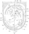
- FIG. 5 is a view showing how the washing water flows in the toilet bowl 14.
- This figure shows the initial stage (first stage) at which the wash water begins to flow into the toilet bowl 14.
- the flow of washing water in the toilet bowl 14 is shown with an arrow.
- the wash water is discharged from each of the first water discharge port 32A and the third water discharge port 32C, and the wash water is not discharged from the second water discharge port 32B.
- the wash water discharged from the first water discharge port 32A forms a flow Dwa that swirls along the first rim conduit 34A.
- the wash water discharged from the third water discharge port 32C forms a flow Dwb that swirls along the third rim conduit 34C.
- the wash water flowing along the rim water guide paths 34A and 34C gradually flows down from the shelves 34a of the rim water guide paths 34A and 34C to the receiving surface portion 26, and forms a flow Dwc that turns while moving downward to the receiving surface portion 26. .
- the water discharge unit 36 from the washing water inflow position Pa in the water flow unit 38 to each of the water discharge ports 32A to 32C.
- the length of the water passage is set so as to satisfy a predetermined condition.
- the length of the water flow path from the inflow position Pa of the wash water in the water flow section 38 to each of the first water discharge port 32A, the second water discharge port 32B, and the third water discharge port 32C is represented by lengths La1, La2, Let it be La3.
- the length La2 of the water flow path of the second water discharge port 32B is set to be longer than the lengths La1 and La3 of the water flow paths of the first water discharge port 32A and the third water discharge port 32C.
- the timing which starts discharge of the washing water of 32A of 1st spouts and 32C of 3rd spouts becomes an equivalent timing.
- “equivalent” includes both the case where the comparison targets are the same and the case where they are substantially the same. Here, it means that both the case where the timing of starting the discharge of the washing water is the same and the case where the timing is almost the same are included. The interpretation of “equivalent” is the same in the following.
- FIG. 6 and 7 are other views showing how the washing water flows in the toilet bowl 14.
- an intermediate stage (second stage) after a lapse of time from the initial stage is shown.
- 6 shows a cross-sectional view taken along the line AA of the flush toilet 10 as in FIG. 3
- FIG. 7 shows a side partial sectional view of the flush toilet 10.
- wash water is discharged into the toilet bowl 14 from the second water discharge port 32B in addition to the first water discharge port 32A and the third water discharge port 32C.
- the flow of the cleaning water discharged from the first water outlet 32A and the third water outlet 32C is the same as in the initial stage.
- Wash water discharged from the second water discharge port 32B forms a flow Dwd that swirls along the second rim conduit 34B.
- the wash water flowing along the second rim conduit 34B gradually falls from the shelves 34a of the second rim conduit 34B to the receiving surface portion 26, and forms a flow Dwe that turns while facing the lower portion of the receiving surface portion 26.
- Flows Dwa, Dwb, Dwc, Dwd, Dwe are formed as a swirl flow swirling in the swirl flow swirl direction Da by the wash water discharged from each of the water discharge ports 32A to 32C.
- the flows Dwc and Dwe turn while going downward from the receiving surface portion 26 of the toilet bowl portion 14, and flow into the recess 30 from the receiving surface portion 26.
- the flow Dwc includes a flow Dwc (1) formed by joining a part of the cleaning water discharged from the second water discharge port 32B and a part of the cleaning water discharged from the third water discharge port 32C.
- the flow Dwc (1) is mainly formed on the receiving surface portion 26 behind the concave portion 30.
- the flow Dwc includes a flow Dwc (2) formed by joining a part of the washing water discharged from the third water discharge port 32C and a part of the washing water discharged from the first water discharge port 32A. It is.
- the flow Dwc (2) is mainly formed on the receiving surface portion 26 of the second divided region Sr2, which is the upstream divided region of the two front divided regions Sr2 and Sr3.
- the main flow Fw is mainly adjacent to the third divided region Sr3 in the swirl flow swirl direction Da from the third divided region Sr3, which is the downstream divided region of the two front divided regions Sr2, Sr3. It is formed on the receiving surface portion 26 in a range extending to the four divided regions Sr4. More specifically, the mainstream Fw is the third divided region on the side (left side) and the front side of the third divided region Sr of the two front divided regions Sr2 and Sr3 when viewed from the recess 30 of the toilet bowl portion 14. It is formed on the receiving surface portion 26 of Sr3 and the fourth divided region Sr4 (see range Sa).
- the main flow Fw becomes a water flow having a strong water flow and a large flow rate when the wash water discharged from each of the first water discharge port 32A and the second water discharge port 32B joins.
- the main flow Fw flows from the receiving surface portion 26 toward the inlet 16 of the trap portion 18 through the recess 30. More specifically, the main flow Fw flows from the third divided region Sr3 to the fourth divided region Sr4 on the receiving surface portion 26, that is, from the front side to the rear side on the receiving surface portion 26, and then into the concave portion 30. On the other hand, it flows into the recess 30 obliquely from the front side (left side and front side).
- the filth in the recess 30 of the toilet bowl portion 14 is swept into the trap portion 18 through the inlet 16 using the above-described drop of the wash water flowing as the swirl flow, in particular, the drop of the wash water flowing as the main flow Fw.
- the head of the cleaning water flowing as the main flow Fw is the difference in height from the confluence position of the cleaning water discharged from each of the first water outlet 32A and the second water outlet 32B to the inlet 16 of the trap portion 18. Hd (see FIG. 7).
- the main flow Fw flows into the recess 30, so that it flows forward after colliding with the right side wall 30 a (first side wall) of the recess 30 in addition to the flow toward the inlet 16 of the trap portion 18.
- a heading flow Dwf is formed. This flow Dwf flows so as to collide with the left wall 30b after flowing along the right wall 30a of the recess 30. The flow Dwf tends to flow while being lifted up by the momentum when it collides with the right side wall 30a and the left side wall 30b of the recess 30.
- This increased flow Dwf merges with the flow Dwc (2) flowing into the recess 30 from the front side toward the rear side on the receiving surface portion 26 (see range Sb), and thereby flows toward the inlet 16 of the trap portion 18. Dwg is formed. Similarly to the flow Dwc (2), the flow Dwg also flows from the front side in the toilet bowl 14 toward the rear side.
- the inner peripheral length of the rim portion 28 from the water outlet to another water outlet becomes longer, it becomes difficult for a sufficient amount of washing water to reach a position away from the water outlet.
- the inner peripheral length of the rim portion 28 from the water outlet to another water outlet can be shortened in the entire rim portion 28, the cleaning water can reach the entire inner peripheral surface of the rim portion 28. It becomes easy to obtain a good rim cleaning ability.
- the main flow Fw toward the inlet 16 of the trap portion 18 is formed by joining the cleaning water discharged from the first water discharge port 32A and the cleaning water discharged from the second water discharge port 32B. Since the second water discharge port 32B is in the front third divided region Sr3, the path through which the wash water flows from the second water discharge port 32B to the inlet 16 of the trap portion 18 rather than being provided in the rear divided region. Can be shortened. As a result, the water flow of the main flow Fw formed by the wash water discharged from the second water discharge port 32B becomes stronger, and the sewage in the toilet bowl portion 14 is pushed to the inlet 16 of the trap portion 18 by the main flow Fw of the strong water flow. Good filth discharge performance can be obtained.
- the main flow Fw toward the inlet 16 of the trap portion 18 is such that the wash water discharged from the first water discharge port 32A and the wash water discharged from the second water discharge port 32B are on the receiving surface portion 26, that is, the toilet bowl portion 14. It is formed by merging on the inner peripheral surface. Therefore, the receiving surface part 26 can be washed by the main stream Fw of strong water, and good toilet bowl washing performance can be obtained.
- the inner peripheral length of the rim portion 28 from one water outlet to another water outlet can be shortened as compared with the case where two water outlets are formed in the rim portion 28.
- the amount of cleaning water discharged from the three water discharge ports 32A to 32C can be reduced, and the width of the shelf 34a of the rim conduit 34 can be reduced. Dimensions such as the height of the standing wall 34b can be reduced.
- the water discharger 36 is configured such that the wash water is discharged from the second water discharge port 32B after the wash water is discharged from the first water discharge port 32A and the third water discharge port 32C, the following advantages are obtained.
- Increasing the ratio of the main flow rate which is the flow rate of the main flow Fw to the total wash water amount used for a single cleaning operation, can increase the main flow rate without increasing the total wash water amount.
- the toilet bowl cleaning ability can be increased.
- the ratio of the main flow rate to the total amount of cleaning water can be increased. Therefore, the waste discharge capacity and the toilet bowl cleaning capacity can be enhanced by increasing the ratio of the main flow rate without increasing the total amount of cleaning water.
- the water discharger 36 has the largest amount of water discharged from the first water outlet 32A, the second largest amount of water discharged from the second water outlet 32B, and the smallest amount of water discharged from the third water outlet 32C. Composed. That is, the cleaning water discharge amount is configured to decrease in the order of the first water discharge port 32A, the second water discharge port 32B, and the third water discharge port 32C. From another viewpoint, the first water discharge port 32A is configured to have a larger discharge amount of the cleaning water than the other two second water discharge ports 32B and 32C.
- the washing water discharge amount here refers to the flow rate (L / s) of washing water per unit time passing through the water outlet.
- the water discharge unit 36 is configured as follows.
- the water flow path in the water flow part 38 from the washing water inflow position Pa (see FIG. 3) from the washing water supply device to each of the water discharge ports 32A to 32C is examined. It is assumed that there are water passages corresponding to each of the first water outlet 32A to the third water outlet 32C.
- the amount of washing water discharged from the water outlet is proportional to the passage cross-sectional area of a portion (hereinafter referred to as a flow rate setting unit) having the smallest passage cross-sectional area in the water flow path for supplying cleaning water to the water outlet.
- the flow rate setting unit of the first water outlet 32A is the first water outlet 32A itself at the downstream end of the water flow path of the first water outlet 32A.
- the flow rate setting unit of the second water discharge port 32B is also the second water discharge port 32B itself, and the flow rate setting unit of the third water discharge port 32C is also the third water discharge port 32C itself.
- the water discharge portion 36 is configured such that the opening area which is the passage cross-sectional area of the first water discharge port 32A is the largest, the opening area of the second water discharge port 32B is the next largest, and the third water discharge port 32C is the smallest. That is, it is configured such that the opening area decreases in the order of the first water outlet 32A, the second water outlet 32B, and the third water outlet 32C.
- the first water outlet 32A is configured to have a larger opening area than the second water outlet 32B and the third water outlet 32C.
- the opening area (passage cross-sectional area) refers to a cross-sectional area in a cross section orthogonal to the water flow direction.
- the magnitude relationship between the respective washing water discharge amounts of the water outlets 32A to 32C is configured to be the same as the magnitude relation of the respective opening areas of the water outlets 32A to 32C.
- FIG. 8 is a diagram showing the inner peripheral lengths Lb1 to Lb3 of the rim conduits 34A to 34C of the rim portion 28.
- the inner peripheral length here refers to the end positions 34Aa to 34Aa to 34C of the rim conduits 34A to 34C from the water discharge ports 32A to 32C at the start positions of the rim conduits 34A to 34C in the horizontal section passing through the rim portion 28.
- the inner peripheral length Lb1 of the first rim conduit 34A is the length of the inner peripheral surface in the range from the first water outlet 32A to the terminal position 34Aa of the first rim conduit 34A.
- the inner peripheral length Lb1 of the first rim conduit 34A is the longest
- the inner periphery Lb2 of the second rim conduit 34B is the second longest
- the inner periphery Lb3 of the third rim conduit 34C is the shortest.
- the inner circumferential length Lb1, the inner circumferential length Lb2, and the inner circumferential length Lb3 are formed so as to be shorter in this order.
- the water discharger 36 has a relationship in magnitude of the amount of wash water discharged from each of the three water discharge ports 32A to 32C, the first rim water conduit 34A to the third rim water conduit 34C connected to each of the three water discharge ports 32A to 32C.
- the circumferential lengths Lb1 to L3 are configured to have the same magnitude relationship.
- the first water discharge port 32A connected to the first rim conduit 34A having the longest inner circumferential length Lb1 has the largest washing water discharge amount.
- the third water discharge port 32C connected to the third rim conduit 34C having the shortest inner circumferential length Lb3 has the smallest amount of discharge of the cleaning water.
- the ratio of the wash water discharge amounts of the three water discharge ports 32A to 32C is connected to each of the three water discharge ports 32A to 32C. It is configured so as to satisfy a relationship that is equivalent to the ratio of the inner circumferential lengths Lb1 to Lb3 of 34C. For example, when the ratio of the inner peripheral lengths Lb1 to Lb3 is 5: 3: 2, the ratio of the cleaning water discharge amounts of the three water discharge ports 32A to 32C satisfies the same relationship as 5: 3: 2. Configured.
- the water discharger 36 is configured to satisfy a relationship in which the ratio of the cleaning water discharge amount of each of the three water discharge ports 32A to 32C is equivalent to the ratio of the opening area of each of the three water discharge ports 32A to 32C. Is done.
- the first water outlet 32A has a larger amount of washing water discharge than the other second water outlet 32B and the third water outlet 32C. Therefore, the toilet bowl portion 14 is washed by the water discharged from the first water outlet 32A. It becomes easy to form the mainstream Fw inside. For this reason, by adjusting the positions of the water discharge ports 32A to 32C, the discharge direction of the wash water, etc., it is possible to set various ways of flowing the main flow Fw in the toilet bowl 14, and the degree of freedom of the washing mode by the wash water Can be enhanced.
- the magnitude relation of the wash water discharge amount of the three water outlets 32A to 32C is the same as the magnitude relation of the inner peripheral lengths of the first rim water conduit 34A to the third rim water conduit 34C connected to the three water outlets 32A to 32C. Configured to be. Therefore, a large amount of cleaning water can be flowed through the first rim conduit 34A having a long inner peripheral length, and a sufficient amount of cleaning water can be easily distributed throughout the first rim conduit 34A.
- the amount of cleaning water used in the third rim conduit 34C can be suppressed by flowing a small amount of cleaning water in the third rim conduit 34C having a short inner peripheral length. For this reason, a sufficient amount of cleaning water is distributed over the entire inner peripheral surface of the rim portion 28 to obtain a good rim cleaning capability, and the amount of cleaning water used for cleaning the entire inner peripheral surface of the rim portion 28 is reduced. Easy to suppress.
- the right-side water passage 38b that supplies cleaning water to the first water outlet 32A has a larger passage cross-sectional area than the left-side water passage 38c in order to increase the amount of washing water discharged from the first water outlet 32A over the other water outlets 32B and 32C. It is necessary to ensure.
- the right side passage having a larger passage cross-sectional area than the first water discharge port 32A is provided in the front divided region.
- the front and rear dimensions of the water channel 38b can be suppressed, and the water discharge portion 36 can be easily downsized. Therefore, it is possible to easily reduce the size of the water discharger 36 as a whole while obtaining good rim cleaning ability, waste discharging ability, and toilet bowl cleaning ability.
- the total amount of cleaning water discharged from the first water outlet 32A and the second water outlet 32B (hereinafter also referred to as the total discharge amount) is larger than the amount of cleaning water discharged from the third water outlet 32C.
- the total discharge amount is larger than the amount of cleaning water discharged from the third water outlet 32C.
- the water discharger 36 has a ratio of the total discharge amount of the first water discharge port 32A and the second water discharge port 32B to the total amount of water used in one cleaning operation of 60% to 80%. It is preferable to be configured so that Here, the total amount of washing water is synonymous with the total amount of washing water discharged from each of the first water outlet 32A to the third water outlet 32C.
- the water discharger 36 is configured such that the ratio of the wash water discharge amount of the first water discharge port 32A to the total wash water amount used in one cleaning operation is 40% to 60%.
- the first water discharge port 32A to the third water discharge port 32C are the third downstream region Sr2 and the third divided region Sr3 on the downstream side of the swirl flow swirl direction Da.
- Each of the divided areas Sr3, the two rear first divided areas Sr1, and the fourth divided areas is formed individually.
- the first water discharge port 32A to the third water discharge port 32C are in the second divided region Sr2 upstream of the swirling flow turning direction Da in the two front divided second regions Sr2 and Sr3. Is not formed.
- Fig.9 (a) is the figure which shows the toilet bowl main body 12 which concerns on a 1st modification.
- the second water discharge port 32B is formed in the second divided region Sr2.
- the small water received by the receiving surface portion 26 of the toilet bowl 14 may be scattered around (see direction Df).
- the small water is transmitted to the inner peripheral surface region along the circumferential direction. There is a possibility of entering from 32B to the right water passage 38b.
- FIG. 10 is a view showing the toilet body 12 according to the first modification of FIG.
- Centrifugal force Fc directed radially outward is applied to the wash water flowing along the inner peripheral surface of the toilet bowl 14.
- the centrifugal force Fc increases as the radius of curvature of the portion through which the washing water flows, and the greater the centrifugal force, the weaker the water flow flowing toward the inlet 16 of the trap portion 18 becomes.
- the second water discharge port 32B is provided in the second divided region Sr2.
- the cleaning water discharged from the water discharge port 32 flows through the inner peripheral surface region at the left and right center position Pa on the front side of the rim portion 28.
- the inner peripheral surface region at the left and right center position Pa since the toilet bowl portion 14 is formed in an elliptical shape having a front-rear dimension larger than the left-right dimension, the radius of curvature is usually likely to be smaller than other positions. Therefore, when the second water discharge port is provided in the second divided region Sr2, the water flow of the cleaning water discharged from the second water discharge port 32B is likely to be weakened by the centrifugal force Fc.
- the wash water discharged from the second water discharge port 32B is used as the center of the left and right sides of the rim portion 28 having a small curvature radius. It is possible to flow toward the inlet 16 of the trap portion 18 without going through the inner peripheral surface area at Pa. Accordingly, the main flow Fw formed by the wash water discharged from the second water outlet 32B is less likely to weaken the water force due to the centrifugal force Fc, and is a better toilet bowl than the second water outlet 32B disposed in the second divided region Sr2. It is possible to obtain cleaning ability and waste discharge ability.
- the left water passage 38c that supplies the cleaning water to the second water discharge port 32B is formed to extend along the front-rear direction on the back side of the left side portion 28L.
- the left water passage 38c is formed on the back side of the left side portion 28L on the side where the third divided region Sr3 where the second water discharge port 32B is formed is located in the left side portion 28L and the right side portion 28R of the rim portion 28. Is done.
- the left water passage 38c is formed so as to straddle the front-rear center line Lb on the back side of the left side portion 28L in plan view. From another viewpoint, the left water passage 38c is not formed so as to straddle the front-rear center line Lb on the back side of the right side portion 28R of the rim portion 28. This advantage will be described.
- the left-side water passage 38c can be arranged with a layout that does not pass through the back side of the left and right center position Pb on the front side of the rim portion 28. Therefore, the water flow path from the washing water inflow position Pa can be made shorter than the water flow path arranged so as to pass through the back side of the right and left center position Pb of the rim portion 28, and the water flow from the second water discharge port 32B.
- the strong washing water can be discharged. As a result, better rim cleaning ability, toilet bowl cleaning ability, and waste discharging ability can be obtained. This effect is obtained more effectively as the position of the second water discharge port 32B approaches the rear side of the third divided region Sr3 of the toilet bowl portion 14.
- the water passage for the first water outlet 32A and the water passage for the second water outlet 32B are connected to the rim portion. It is necessary to arrange side by side in the left-right direction behind the right side portion 28R of 28.
- the right-side water passage 38b for the first water outlet 32A and the left-side water passage 38c for the second water outlet 32B are arranged in the left-right direction behind the right-side portion 28R of the rim portion 28. It will be better without placement. Therefore, the width dimension of the back side portion of the right side portion 28R of the rim portion 28 can be reduced. Thereby, as shown in FIG. 1, FIG. 2, the width dimension of the side part 12b extended to the side from the upper end edge of the toilet bowl part 14 among the upper surface parts 12a of the toilet bowl main body 12 can be made small.
- a straight section 34Bb that extends linearly at a position away from the second water discharge port 32B in the swirl flow swirl direction Da is formed on the inner peripheral surface of the second rim conduit 34B.
- a curvature decreasing section 34Bc formed so that the curvature decreases as the distance from the second water outlet 32B increases. Is formed.
- a straight section 34Cb that extends linearly at a position away from the third water discharge port 32C in the swirl flow swirl direction Da is also formed on the inner peripheral surface of the third rim conduit 34C.
- a curvature decreasing section 34Cc formed such that the curvature decreases as the distance from the third water outlet 32C increases in a continuous range from the third water outlet 32C to the straight section 34Cb. Is formed.
- curvature decreasing sections 34Bc and 34Cb continuous from the water outlets 32B and 32C are formed on the inner peripheral surfaces of the rim conduits 34B and 34C. Therefore, the strong wash water immediately after being discharged from each of the water outlets 32B and 32C flows through the section having a large radius of curvature in the range from the discharge from each of the water outlets 32B and 32C to passing through the straight sections 34Bb and 34Ca. Therefore, it becomes difficult to apply a large centrifugal force to the wash water flowing through the range. For this reason, the water flow toward the inlet 16 of the trap portion 18 after being discharged from the water outlets 32B and 32C is less likely to weaken from the strong water state immediately after being discharged from the water outlets 32B and 32C. As a result, the filth can be pushed in by the strong water flow, and a better filth discharge performance can be obtained.
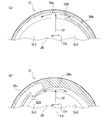
- Fig.11 (a) is a figure which shows the structure around the 2nd water discharge port 32B which concerns on embodiment.
- the second water discharge port 32B includes an inner standing wall 34b (hereinafter also referred to as an inner standing wall 34b (1)) and an outer standing wall 34b (hereinafter referred to as an outer standing wall 34b (2)) that are adjacent in the radial direction of the toilet bowl 14. (Also called).
- the circumferential end portion 34ba of the outer standing wall portion 34b (2) and the circumferential end portion 34bb of the inner standing wall portion 34b (1) are virtual extending from the center point Cp of the toilet bowl portion 14. It arrange
- alignment includes a case where the angle range where the two standing wall portions 34b overlap in the circumferential direction is 3 ° or less when viewed from the center point Cp of the toilet bowl portion 14. It can be said that the two standing wall portions 34b are arranged so that the angle range overlapping in the circumferential direction is 3 ° or less when viewed from the center point Cp of the toilet bowl portion 14. This advantage will be described.
- FIG. 11B is a diagram showing a structure around the second water discharge port 32B according to the second modification.
- the circumferential end portions 34ba and 34bb of the two standing wall portions 34b do not line up on the imaginary line Lc, and the angle range where the two standing wall portions 34b overlap in the circumferential direction becomes large.
- separate water channel portions 40 connected to the upstream end and the downstream end of the folded portion 38ca are formed side by side in the radial direction.
- the two inner wall surfaces 38f opposed in the radial direction at the folded-back portion 38ca are directed to the abutting position 38g of the folded-back portion 38ca because the rim conduit 34A is formed radially inward with respect to the folded-back portion 38ca. It becomes easy to form so that it may become narrow. Therefore, the width dimension of each water channel portion 40 is also easily formed so as to become narrower as it approaches the folded portion 38ca. For this reason, in the path Rb from the front-rear extending portion 38cb of the left water passage 38c to the second water discharge port 32B via the folded portion 38ca, the portion having a smaller passage cross-sectional area than the second water discharge port 32B is the inner vertical wall portion.
- the 2nd water discharge port 32B is formed in the division area Sr3 of the front side of the toilet bowl part 14, it exists in the position where it is hard to be visually recognized by the user at the time of normal use. Therefore, it arrange
- “during normal use” refers to a situation in which a user sits on a toilet seat and uses a toilet after approaching the flush toilet 10 from the front.
- FIG. 12 is a view showing a structure around the third water discharge port 32C.
- the width dimension of the left water passage 38c at the position where the left water passage 38c and the front-rear center line Lb overlap is defined as W1.
- a width change region 38h is formed so that the width dimension gradually increases toward the rear from the front-rear center line Lb.
- the third water discharge port 32C is formed behind the reference position 38i.
- the third water discharge port 32C is formed at a position ahead of the reference position 38i (for example, the range Sd), it is necessary to secure a wall portion for guiding the cleaning water to the third water discharge port 32C around the third water discharge port 32C.
- the water passage from the periphery to the second water discharge port 32B tends to become narrow.
- the third water outlet 32C is formed behind the reference position 38i, the water passage toward the second water outlet 32B is less likely to be narrowed by the wall portion for guiding the wash water to the third water outlet 32C. It becomes easy to supply a sufficient amount of washing water to the second water discharge port 32B.
- the flush toilet 10 has been described with an example of using the wash-off method as the cleaning method, the inside of the toilet bowl 14 may be cleaned by a cleaning method combined with another method such as a siphon type or a siphon-zette type.
- a cleaning method combined with another method such as a siphon type or a siphon-zette type.
- the flush toilet 10 has been described with respect to an example in which a water supply direct pressure system is used as a water supply system, a water supply system such as a gravity water supply system using gravity or a flash valve system may be used.
- the toilet body 12 has been described by taking a wall-mounted toilet as an example, it may be a floor-standing toilet installed on the floor surface of a toilet room.
- the toilet body 12 may be made of resin or the like in addition to pottery.
- the shelf 34 a of the rim conduit 34 is such that the gradient of the upper surface portion connected to the upper edge 26 a of the receiving surface portion 26 is gentler than the gradient of the inner surface portion of the receiving surface portion 26 connected to the upper edge 26 a of the receiving surface portion 26. It only has to be formed. As long as these conditions are satisfied, the upper surface portion of the shelf 34a may be formed in a flat shape as shown in FIG. 1 or the like, or may be formed in an arc shape. Further, the rim conduit 34 has a vertical cross-sectional shape orthogonal to the swirl flow swirl direction D formed into a curved surface that is continuous by the upper surface portion of the shelf portion 34a of the rim conduit 34 and the lower surface portion of the overhang portion 34c. May be.
- the rim conduit 34 may not have the overhang portion 34c. Further, the example has been described in which the three rim conduits 34A to 34C are formed so as to be separated from the end positions 34Aa, 34Ba, 34Ca without being continuous with other rim conduits. And may be formed continuously.
- the three water discharge ports 32A to 32C may be formed individually in each of the three divided regions among the four divided regions Sr1 to Sr4. From this viewpoint, the positions of the three water discharge ports 32A to 32C are not limited to the contents of the embodiment.
- FIG. 13 is a schematic diagram showing an example of an arrangement pattern of the water discharge ports 32A to 32C that can obtain the effect (1).
- the first water outlet 32A is provided in the first divided region Sr1
- the second water outlet 32B is provided in the second divided region Sr2, and the fourth division.
- the third water discharge port 32C may be formed in the region Sr4.
- a first water discharge port 32A is formed in the first divided region Sr1
- a second water discharge port 32B is formed in the second divided region Sr2
- a third water discharge port 32C is formed in the third divided region Sr3. May be.
- FIG. 13A a first water discharge port 32A is formed in the first divided region Sr1
- a second water discharge port 32B is formed in the second divided region Sr2
- a third water discharge port 32C is formed in the third divided region Sr3. May be. Further, as shown in FIG.
- a first water discharge port 32A is formed in the second divided region Sr2
- a second water discharge port 32B is formed in the third divided region Sr3
- a third water discharge port 32C is formed in the fourth divided region Sr4. May be.
- the first water discharge port 32A having the largest cleaning water discharge amount may be formed not in the rear divided region but in the front divided region. In any case, it can be said that, out of the four divided areas Sr1 to Sr4, the water outlet is not formed in one divided area, and the water outlet is individually formed in the other three divided areas.
- the three water discharge ports 32A to 32C may be formed so that at least one of the four divided regions Sr1 to Sr4 is included in each of the four divided regions Sr1 to Sr4, and straddles adjacent divided regions. It may be formed as follows. For example, while forming the second water discharge port 32B in the third divided region Sr3 and the third water discharge port 32C in the fourth divided region Sr4, the first water discharge port 32A straddles the first divided region Sr1 and the second divided region Sr2. You may form so that. In addition, the second water discharge port 32B may be formed so as to straddle the adjacent divided regions, or the third water discharge port 32C may be formed so as to straddle the adjacent divided regions. Good.
- the three water outlets 32A to 32C are arranged so that an angle range of 1/4 or more is separated from the center point Cp of the toilet bowl portion 14. It may be. Further, the washing water discharge amount and the opening area of the three water discharge ports 32A to 32C are not limited to the contents of the embodiment. For example, the wash water discharge amounts of the three water discharge ports 32A to 32C may be the same, or only the wash water discharge amounts of two of the three water discharge ports 32A to 32C may be the same.
- the toilet bowl portion 14 has two divided regions separated by the front-rear center line Lb.
- the two divided areas here are composed of a first divided area Sr1 and a fourth divided area Sr4, and the other is a second divided area Sr2 and a third divided area. It is composed of Sr3.
- the two water discharge ports include a first water discharge port 32A formed in one of the two divided regions Sr1 to Sr4 and a second water discharge port 32B formed in the front divided region. As long as it is included.
- the second water discharge port 32B may be formed in the same divided region as the divided region in which the first water discharge port 32A is formed, or may be formed in another divided region.
- the positions of these two water discharge ports 32A and 32B are not limited to the contents of the embodiment.
- FIG. 14 is a schematic diagram illustrating an example of an arrangement pattern of the water discharge ports 32A and 32B that can obtain the effect (2).
- the first water discharge port 32A is formed in the first divided region Sr1
- the second water discharge port 32B is formed in the third divided region Sr3. Also good.
- the first water discharge port 32A may be formed in the second divided region Sr2
- the second water discharge port 32B may be formed in the third divided region Sr3.
- a third water discharge port 32C may be further formed in the fourth divided region Sr4.
- each of the water discharge ports 32A to 32C of the rim portion 28 of the toilet bowl portion 14 is disposed so as to overlap in the vertical direction.
- each of the water discharge ports 32A to 32C of the rim portion 28 has any one of the water discharge ports 32A to 32C, or all the water discharge ports 32A to 32C do not overlap in the vertical direction.
- the front-rear center line Lb of the toilet bowl portion 14 is divided in the left-right direction by equally dividing the front-rear dimension of the inner surface portion of the toilet bowl portion 14 in a plan view of the horizontal section passing through the lowermost spout. It is defined by a straight line that extends.
- the water discharger 36 joins the wash water discharged from the first water discharge port 32A and the wash water discharged from the second water discharge port 32B to generate the main flow Fw toward the inlet 16 of the drainage passage unit. Configured to form.
- the water discharger 36 can be configured to form such a main flow Fw by adjusting the positions of the water discharge ports 32A and 32B, the cleaning water discharge amount, and the cleaning water discharge direction.
- discharge start timing the timing of starting the discharge of the wash water from the first water outlet 32A and the third water outlet 32C.
- the discharge start timing may be earlier than the discharge start timing of the wash water from the second water discharge port 32B, and the discharge start timing may be shifted between the first water discharge port 32A and the third water discharge port 32C.
- the water discharge unit 36 adjusts the passage cross-sectional area of the water flow path corresponding to the water discharge ports 32A to 32C in order to adjust the discharge amount of the cleaning water at each of the water discharge ports 32A to 32C has been described.
- the washing water discharge amount may be adjusted by a throttle valve or the like provided in the middle of the water flow path for each of the water discharge ports 32A to 32C.
- a valve mechanism such as an electrically driven valve may be used to adjust the timing for starting the discharge of the wash water from each of the water discharge ports 32A to 32C.
- the three water outlets may include a first water outlet having a larger amount of washing water discharged than the other two water outlets. According to this aspect, it becomes easy to form a mainstream in the toilet bowl by the wash water discharged from the first water outlet. For this reason, by adjusting the positions of the three water outlets, the discharge direction of the washing water, and the like, various ways of flowing the main flow in the toilet bowl can be set, and the degree of freedom of the washing mode by the washing water can be increased.
- the first spout may be provided in a rear divided area of the four divided areas.
- the water passage that supplies the cleaning water to the first water outlet has a larger passage cross-sectional area in order to increase the amount of cleaning water discharged from the first water outlet than the other water outlets.
- the front and rear dimensions of the water passage having a larger passage cross-sectional area than the first water outlet provided in the front divided area It becomes easy to make the water discharge part small. Therefore, the whole water discharge part can be easily miniaturized while obtaining good rim cleaning ability.
- the flush toilet of the 4th mode of the 1st invention is adjacent to one side of the peripheral direction to the divided field in which the 1st spout is formed among the four divided fields in the 2nd mode or the 3rd mode.
- the other two spouts need not be formed in the divided region.
- the flush toilet of the fifth aspect of the first invention is the flush toilet according to any one of the first to fourth aspects, wherein the rim portion is formed to extend from one of the three water outlets to one side in the circumferential direction. It has a rim waterway, and the water discharge part has the same size relationship of the amount of washing water discharged from each of the three water outlets as the size relationship of the inner peripheral lengths of the three rim water channels connected to each of the three water outlets. You may be comprised so that it may become. According to this aspect, it is possible to flow a large amount of washing water through the rim conduit having a long inner circumference, and it is easy to allow a sufficient amount of washing water to reach the entire rim conduit.
- the amount of cleaning water used in the rim conduit can be suppressed by flowing a small amount of cleaning water in the rim conduit having a short inner peripheral length. For this reason, it is easy to suppress the amount of cleaning water used for cleaning the entire inner peripheral surface of the rim part, while obtaining a sufficient amount of cleaning water to reach the entire inner peripheral surface of the rim part and obtaining a good rim cleaning ability. it can.
- the water discharger is configured so that the amount of the wash water discharged from each of the three water discharge ports is large and small. You may comprise so that the magnitude relationship of each opening area may become the same.
- a flush toilet according to a seventh aspect of the first invention is the flush toilet according to any one of the first to sixth aspects, wherein the three spouts are divided areas on one side in the circumferential direction of the two divided areas on the front side. Each of the two rear divided regions may be formed individually.
- the small water transmitted along the inner peripheral surface region is difficult to enter from the spout to the back side. . Therefore, the possibility that urine components remain on the back side of the spout can be suppressed, and the generation of dirt and odor can be prevented accordingly.
- the flush toilet of the eighth aspect of the first invention is the flush toilet according to any one of the first to seventh aspects, wherein one of the three water outlets is circumferential in the two divided areas on the front side.
- the water discharge portion has a water passage that supplies cleaning water to one water outlet, and the water passage is one of the side portions on the left and right sides of the rim portion in the circumferential direction. You may form so that it may extend along the front-back direction in the back side of the side part of the side with a side division area.
- the water passage can be arranged in a layout that does not pass through the back side of the left and right center position on the front side of the rim portion.
- the eighth aspect at the downstream end of the water passage, there is a folded portion that circulates the washing water supplied from the upstream side so as to be led to one outlet.
- One spout is formed partly by two wall portions adjacent in the radial direction of the toilet bowl portion, and the circumferential end portions of the two wall portions are on a virtual line extending from the center point of the toilet bowl portion. It may be arranged to line up.
- the flush toilet according to the tenth aspect of the first invention is the drainage apparatus according to any one of the first to ninth aspects, wherein the toilet body communicates with the inside of the toilet bowl through an inlet formed at the bottom of the toilet bowl.
- the three water outlets include a first water outlet formed in any one of the divided areas and a second water outlet formed in the front divided area;
- the cleaning water discharged from the first water outlet and the cleaning water discharged from the second water outlet may be joined to form a main flow toward the inlet.
- the main flow toward the inlet of the drainage passage portion is formed by joining the wash water discharged from the first water discharge port and the wash water discharged from the second water discharge port.
- the path through which the wash water flows from the second water discharge port to the inlet of the drainage passage can be made shorter than that provided in the rear divided region.
- the mainstream water formed by the wash water discharged from the second outlet becomes stronger, and the sewage in the toilet bowl is pushed to the entrance of the drainage passage by the mainstream of strong water, so that good filth discharge performance is achieved. It will be obtained.
- the flush toilet of the twelfth aspect of the first invention is the eleventh aspect, wherein the first water outlet, the second water outlet, and the third water outlet are sequentially disposed in one of the circumferential directions, and the water outlet is the first water outlet.
- the washing water discharge amount of the sum total of the 2nd spout may be comprised so that it may be larger than the wash water discharge amount of the 3rd spout. According to this aspect, it can be expected that the amount of cleaning water more than half of the total amount of cleaning water used in one cleaning operation is used for forming the mainstream. Therefore, the flow rate of the main stream of strong water can be increased, and particularly good waste discharge performance can be obtained by pushing the filth in the toilet bowl to the entrance of the drainage passage by the main stream of strong water and large flow rate.
- the flush toilet according to the thirteenth aspect of the first invention is characterized in that the water discharge portion is flushed from the second water outlet after the wash water is discharged from the first water outlet and the third water outlet. May be configured to be discharged.
- Increasing the ratio of the main flow rate to the total amount of cleaning water used for a single cleaning operation can increase the waste discharge capacity without increasing the total amount of cleaning water.
- the ratio of the main flow rate to the total amount of cleaning water can be increased. Therefore, the waste discharge performance can be enhanced by increasing the ratio of the main flow rate.
- the flush toilet of the fourteenth aspect of the first aspect of the invention is any one of the tenth to thirteenth aspects, wherein the toilet bowl portion is a left-right center line that bisects the left-right dimension of the outer surface portion of the toilet body in plan view And the four divided regions divided by the front and rear center lines, and the second water discharge port may be formed in a divided region on one side in the circumferential direction among the two divided regions on the front side. According to this aspect, the wash water discharged from the second water discharge port can flow toward the entrance of the drainage passage portion without passing through the inner peripheral surface region at the left and right center position of the toilet bowl portion having a small curvature radius. become.
- the main flow formed by the wash water discharged from the second water discharge port is less likely to weaken the water force due to the centrifugal force, and the second water discharge port is formed in the other divided region in the circumferential direction of the two front divided regions. Rather than doing so, it will be possible to obtain a better waste discharge capacity.
- the flush toilet according to the fifteenth aspect of the first invention is the flush toilet according to any one of the tenth to fourteenth aspects, wherein the water discharger is a wash water discharged from the first water discharge port, and a wash water discharged from the second water discharge port.
- the inner peripheral surface of the toilet bowl portion can be cleaned by the mainstream of strong water, and good toilet bowl cleaning performance can be obtained.
- a toilet bowl body having a toilet bowl, a drainage passage communicating with the toilet bowl through an inlet formed at the bottom of the toilet bowl, and a water discharger for discharging washing water into the toilet bowl
- the toilet bowl has a receiving surface for receiving filth, and a rim connected to the upper edge of the receiving surface
- the water discharge portion has two water discharge ports formed in the rim portion, and discharges wash water from the two water discharge ports into the toilet bowl portion on one side in the circumferential direction
- the toilet bowl portion has two divided regions that are divided by a front-rear center line that bisects the front-rear dimension of the inner surface portion of the toilet bowl portion in plan view,
- the two spouts include a first spout formed in one of the two divided regions, and a second spout formed in the front divided region
- the water discharge unit is configured to join the wash water discharged from the first water discharge port and the wash water discharged from the second water discharge port to form a main flow toward the inlet. Flush
- Patent Document 2 a first flushing port is provided in the rear side of the toilet bowl part and one of the left and right sides, and a second flushing port is provided in the rear side of the toilet bowl part and the left and right side areas.
- a toilet bowl has been proposed. In this flush toilet, the wash water discharged from each water outlet flows into the recess of the toilet bowl, and the accumulated water in the recess is stirred in the vertical direction. It is described that such agitation of the stored water in the recesses makes it possible to sink and discharge the filth in the recesses easily, and improve the filth discharge performance.
- Patent Document 2 As a result of studying the structure of Patent Document 2, the present inventor has recognized the following problems.
- the flush toilet of Patent Document 2 has a long path through which the wash water flows from each water outlet to the entrance of the drain pipe. Therefore, the wash water discharged from the water discharge port reaches the recessed portion in a state where the water force is relatively weakened. For this reason, there is a room for improvement in terms of filth discharge performance because the water flow for draining filth into the drainage pipe tends to be insufficient.
- the invention described in the first item has been made in view of such a problem, and an object thereof is to provide a flush toilet capable of obtaining a good waste discharge capability.
- FIG. 15 is a side sectional view of a flush toilet 300 according to the second embodiment
- FIG. 16 is a plan view of the flush toilet 300
- FIG. 17 is a top view of flush toilet 300 when cut along a horizontal plane along line AA in FIG.
- the lateral direction of the flush toilet 300 is defined as the X axis
- the longitudinal direction of the flush toilet 300 is defined as the Y axis
- the height direction is defined as the Z axis.
- the X axis positive direction is “right direction”
- the X axis negative direction is “left direction”.
- the left direction is the first direction
- the other direction on the left and right is referred to as the second direction.
- the left direction is the first direction and the right direction is the second direction.
- the flush toilet 300 includes a toilet body 302 made of ceramic.
- the toilet body 302 is a wall-mounted toilet that is attached in a state of being hung on the wall surface 210 of the toilet room.
- a box containing a hot water cleaning device such as a local cleaning device, a toilet lid and a toilet seat that are rotatably supported by the box are disposed above the toilet body 302.
- the toilet body 302 has a toilet bowl 310, a drainage pipe section 312, and a peripheral wall section 314.
- the drainage pipe part 312 is formed in the lower part of the toilet bowl part 310.
- the peripheral wall part 314 shields internal structures such as the toilet bowl part 310 and the drainage pipe part 312.
- the drainage pipe part 312 forms a U-shaped sealing part 316e at the connection part with the toilet bowl part 310.
- stagnant water is always stored, thereby blocking the odor of the drainage pipe portion 312.
- the filth falling on the sealed water portion 316e is pushed out together with the staying water by the washing water.
- the toilet bowl 310 is formed in an elliptical shape whose front-rear dimension is larger than the left-right dimension in plan view.
- the toilet bowl 310 includes a bowl-shaped receiving surface 330 for receiving filth, a rim portion 308 that is connected to the upper edge of the receiving surface 330 and forms the upper edge of the toilet bowl 310, and the receiving surface 330.
- a concave portion 316 formed to be depressed downward from the lower edge portion.
- the receiving surface portion 330 is formed to incline with a downward slope toward the center side.
- the concave portion 316 is formed in a bottomed shape, and an inlet of the sealing portion 316e is opened in the bottom portion 316k. A portion of the accumulated water is stored in the recess 316.
- the recess 316 will be described later.
- FIG. 19 is a diagram for explaining the central axis M1 of the recess 316 and the shape of the recess 316.
- the concave portion 316 has a front end portion 316f corresponding to a vertex shared by the left and right sides when seen in a plan view.
- a straight line extending in the front-rear direction by dividing the left-right range Lx of the recess 316 into two equal parts is denoted as a central axis M1.
- a straight line that passes through the front end 316f and extends in the left-right direction is denoted as a straight line N1.
- An intersection point of the central axis M1 and the straight line N1 is denoted as a point P.
- a left end 220 a is located on the left standing wall 220 of the recess 316, and a right end 222 a is located on the right standing wall 222.
- the front end portion 316f is located on the central axis M1.
- the toilet bowl portion 310 has four divided regions Sr1 to Sr4 divided by the central axis M1 and the straight line N1 in a plan view.
- the left divided region is the first divided region Sr1 and the right divided region is the fourth divided region Sr4 with respect to the central axis M1.
- the left divided region is the second divided region Sr2 and the right divided region is the third divided region Sr3, which is the front side with respect to the straight line N1 and the central axis M1.
- a first rim conduit 324a mainly provided on the left side, a second rim conduit 324b mainly provided on the right side, and mainly on the left rear are provided in the rim portion 308 .
- Three water conduits of the third rim water conduit 324c are formed.
- the three water conduits of the first rim water conduit 324a, the second rim water conduit 324b, and the third rim water conduit 324c are collectively referred to as “water conduit 324”.
- the rim portion 308 has three water discharge ports, a first water discharge port 322a, a second water discharge port 322b, and a third water discharge port 322c.
- the three water outlets of the first water outlet 322a, the second water outlet 322b, and the third water outlet 322c are collectively referred to as “water outlet 322”.
- the water outlet 322 will be described later.
- the water outlet 322 is formed in the water conduit 324 and opens toward the rim water passage 320 so as to be continuous with the rim water passage 320 described later.
- the first water outlet 322a is provided at the downstream end of the first rim water conduit 324a
- the second water outlet 322b is provided at the downstream end of the second rim water conduit 324b
- the third water outlet 322c is the third rim water conduit 324c. At the downstream end.
- the cleaning water supplied from the water supply pipe 304 that is a part of the cleaning water supply device is supplied to each of the rim water conduits 324 through the inflow passage 238a and the water conduit 238b.
- the cleaning water supplied to the rim water conduit 324 is discharged from the water outlet 322 toward the rim water passage 320 described later.
- the discharged wash water turns in the circumferential direction along the rim water passage 320.
- the direction of turning in the circumferential direction of the cleaning water is simply referred to as “turning direction”.
- a first rim water passage 320a, a second rim water passage 320b, and a third rim water passage 320c are formed in the rim portion 308 so as to extend from each of the three water outlets 322 in the circumferential direction of the toilet bowl portion 310. Is done.
- the three rim water passages 320a, 320b, and 320c are collectively referred to as “rim water passage 320”.
- the first rim water passage 320a extends in the circumferential direction from the first water outlet 322a to the vicinity of the second water outlet 322b on the downstream side in the turning direction.
- the second rim water passage 320b extends in the circumferential direction from the second water outlet 322b to the vicinity of the third water outlet 322c on the downstream side in the turning direction.
- the third rim water passage 320c extends in the circumferential direction from the third water outlet 322c to the vicinity of the first water outlet 322a on the downstream side in the turning direction.
- the first rim water passage 320a, the second rim water passage 320b, and the third rim water passage 320c may be partially connected.
- the rim water passage 320 is formed to swirl the cleaning water discharged from the water outlet 322.
- the rim water passage 320 includes a shelf portion 326b extending from the upper end edge 326c of the receiving surface portion 330 toward the outside of the toilet bowl portion 310, and a side wall portion rising from the outer peripheral end portion of the shelf portion 326b. 326a, an overhang portion 318 extending from the upper end portion of the side wall portion 326a toward the inside of the toilet bowl 310, and a turning portion 332 that bends a part of the flow of the washing water inward.
- the turning portion 332 will be described later.
- each shelf 326b in the rim water passage 320 is formed smaller toward the downstream side as shown in FIG. With this configuration, the cleaning water discharged from the water discharge port 322 gradually flows down to the receiving surface portion 330 as it flows downstream.
- An inner edge 318 a of the overhang portion 318 is formed so as to protrude inward from the upper end of the toilet bowl portion 310.
- the upper surface of the overhang portion 318 is flattened so as to be a support surface of the toilet seat.
- a rim water passage 320 serving as a path for the swirling water flow is formed.
- the shape of the recess in plan view will be described. From the viewpoint of efficiently cleaning the standing wall of the recess with a small amount of cleaning water, it is advantageous that the area of the standing wall to be cleaned is small. Since the area of the standing wall is determined by the length of the contour of the peripheral edge of the concave portion in plan view and the height dimension of the vertical wall, the area of the vertical wall can be reduced by reducing the length of the contour of the peripheral edge of the concave portion. In other words, it is advantageous to make the length of the contour of the peripheral edge of the recess small to efficiently clean the recess.
- the left and right dimensions and the front and rear dimensions of the recess be greater than a predetermined dimension.
- a rectangular shape, an elliptical shape, a shape obtained by combining these in the front-rear direction, and a shape obtained by deforming them can be considered.
- the contour length of the peripheral edge of the concave portion is shorter than that of a rectangle or an ellipse. Therefore, from the viewpoint of efficiently cleaning the standing wall of the concave portion, the outline of the peripheral edge of the concave portion is advantageous to be triangular.
- the shape of the concave portion of the toilet bowl portion being substantially triangular means that each side constituting the triangle is constituted by a curve or a straight line having a curvature radius of 100 mm or more in a plan view.
- the angles of the three corners can be formed as acute angles of 90 degrees or less in plan view.
- FIG. 20 is an enlarged plan view showing the inner edge of the recess 316.
- the recess 316 has a substantially triangular shape that is partitioned by three standing walls corresponding to the three sides of the triangle 230 with the bottom 230u positioned behind the left and right sides 230h and 230m in plan view.
- the left standing wall 220 and the right standing wall 222 correspond to the left and right sides 230h and 230m, and the rear standing wall 224 corresponds to the bottom 230u.
- the three standing walls of the left standing wall 220, the right standing wall 222, and the rear standing wall 224 are collectively referred to as “standing wall 226”.
- the recess 316 includes a front end 316f corresponding to the vertex 230a shared by the left and right sides 230h and 230m, a left corner 316h corresponding to the left rear vertex 230c, and a right corner 316m corresponding to the right rear vertex 230b.
- a front end 316f corresponding to the vertex 230a shared by the left and right sides 230h and 230m
- a left corner 316h corresponding to the left rear vertex 230c
- a right corner 316m corresponding to the right rear vertex 230b.
- three corners including a front end portion 316f, a left corner portion 316h, and a right corner portion 316m are formed so as to pass through the three vertices of the triangle 230, respectively.
- the three corners of the front end portion 316f, the left corner portion 316h, and the right corner portion 316m are collectively referred to as “corner portion 228”.
- the radius of curvature of the front end portion 316f is excessively large, the water area in the concave portion 316 may turn without lowering, and in this case, the downward flow cannot be sufficiently formed and the discharge performance may be lowered. .
- the radius of curvature of the front end portion 316f is excessively small, it may be difficult to release the material injected into the mold from the mold.
- the concave portion 316 is formed in a curved line or a straight line in which the curvature radii of the left standing wall 220, the right standing wall 222, and the rear standing wall 224 are 100 mm or more.
- the standing wall of the recess is a convex surface protruding inward in a plan view
- the flow along the standing wall hardly collides with the corner.
- the concave portion 316 is formed in a concave surface that bulges outward in a plan view.
- the concave portion 316 is formed such that the curvature radius of the left standing wall 220, the right standing wall 222, and the rear standing wall 224 is larger than the curvature radius of the front end portion 316f.
- the three water outlets 322 are individually formed in each of the three divided areas among the four divided areas Sr1 to Sr4.
- the first water outlet 322a may be arranged in the first divided area Sr1, the second water outlet 322b in the third divided area Sr3, and the third water outlet 322c in the fourth divided area Sr4.
- one of the first water outlet 322a and the second water outlet 322b may be disposed in the second divided region Sr2.
- the three water discharge ports 322 can be arrange
- the three water outlets 322 are formed such that the first water outlet 322a is formed on the left side of the concave portion 316 and the second water outlet 322b is formed in front of the concave portion 316.
- a water discharge port 322 c is formed on the right side of the recess 316 and behind the rear standing wall 224.
- the front end portion 316f of the recess 316 is located in a triangle connecting the three water outlets 322 in plan view. Further, the second water outlet 322b is located in the left-right range Lx of the recess 316, and the third water outlet 322c is located outside the left-right range Lx of the recess 316.
- the three water outlets 322 surround the recess 316 in the circumferential direction, and the cleaning water can efficiently clean the recess 316.
- each of the three water outlets discharges the cleaning water corresponding to each standing wall.
- the three water outlets discharge water corresponding to the next vertical wall of the vertical wall closest to each water outlet in the direction in which the cleaning water flows. That is, in the flush toilet 300, the first water outlet 322a is provided corresponding to the right standing wall 222, the second water outlet 322b is provided corresponding to the rear standing wall 224, and the third water outlet 322c is provided on the left standing wall 220. Correspondingly provided.
- the first main flow 362 of the first water discharge port 322a falls on the right standing wall 222
- the first main flow 372 of the second water discharge port 322b falls on the rear standing wall 224
- the third discharge The first main flow 382 of the water port 322c falls on the left standing wall 220.
- the first mainstreams 362, 372, and 382 are configured to fall around the receiving surface portion 330 about a half and fall into the recess 316.
- FIG. 21 is a diagram schematically illustrating how the wash water flows in the toilet bowl 310.
- the wash water supplied from the water supply pipe 304 is supplied to the three rim water conduits 324 through the water conduit 238b.
- the cleaning water 358, 368, and 378 supplied to the rim water conduit 324 is discharged from the water outlet 322 to the rim water passage 320, and the first main flow 362, 372, and 382 curved inward from the rim water passage 320, and the rim passage.
- a second main flow 364, 374, 384 that swirls along the water channel 320.
- the main flow of washing water means a main flow in which a large proportion of the washing water flows in the same manner, and a water discharge flow from one outlet may form a plurality of main flows.
- a side wall portion 326a that is curved in an arc shape in plan view is formed so as to surround the concave portion 316. Due to the curved action of the side wall portion 326a, a water flow that is bent along the side wall portion 326a and turns in the circumferential direction is formed in the cleaning water.
- the side wall portion 326a of the rim water passage 320 is provided with a turning portion 332 that bends inward a part of the flow of the washing water swirling in the circumferential direction along the side wall portion 326a.
- the turning portion 332 bends a part of the flow of the cleaning water inward, separately from the bending action of the side wall portion 326a.
- the turning portion 332 includes a first convex surface portion 334a, a second convex surface portion 334b, and a third convex surface portion 334c in which a part of the side wall portion 326a extends inward from both sides in the circumferential direction.
- the first convex surface portion 334a, the second convex surface portion 334b, and the third convex surface portion 334c are collectively referred to as “convex surface portion 334”.
- the convex surface portion 334 is provided in the rim water passage 320 on the downstream side of the water discharge port 322.
- the first convex surface portion 334a is provided near the first water outlet 322a between the first water outlet 322a and the second water outlet 322b.
- the second convex surface portion 334b is provided near the second water discharge port 322b between the second water discharge port 322b and the third water discharge port 322c.
- the third convex surface portion 334c is provided between the third water outlet 322c and the first water outlet 322a so as to approach the third water outlet 322c.
- FIG. 18 is a schematic diagram showing the periphery of the first convex surface portion 334a in an enlarged manner.
- the outline 354a of the side wall portion when there is no convex surface portion is indicated by a broken line.
- the guidance part 334as, the protrusion part 334at, and the downstream part 334au are formed in this order from the upstream.
- the protrusion 334at is a portion that protrudes inward from the leading portion 334as and the downstream portion 334au on both sides thereof.
- the washing water discharged from the first water discharge port 322a forms a first water flow 360.
- the water flow 360s in the outer portion of the first water flow 360 collides with the leading portion 334as and flows inward along the leading portion 334as.
- the water flow 360u in the inner portion of the first water flow 360 passes through the protrusion 334at without colliding with the leading portion 334as and swirls in the circumferential direction along the downstream portion 334au and the side wall portion 326a connected to the downstream portion 334au. .
- the water flow 360s is drawn so as to intersect with the water flow 360u.
- the water flow 360s and the water flow 360u are influenced by each other, and the desired first main flow 362 and the second main flow are obtained. 374.
- the first convex surface portion 334a can form a water flow 360s that swirls from the first water flow 360 and a water flow 360u that curves inward from the swirling water flow 360s.
- the shape of the first convex surface portion 334a to give the water flow 360s and the water flow 360u with a desired amount of water, water flow, and direction, the first main flow 362 and the second main flow 374 can be generated.
- action are the same as that of FIG. 18 used about the 1st convex surface part 334a, and description, The overlapping description is abbreviate
- the flow of the cleaning water can be precisely controlled by providing the turning portion 332.
- the position of the mainstream direction change can be determined, it is difficult to be influenced by the shape of the shelf portion 326b of the rim portion 308 and the shape of the toilet bowl portion 310, and it is easy to form a target washing water flow. Become.
- the first main flow 362 falls toward the right standing wall 222 while widely washing the receiving surface portion 330, flows along the right standing wall 222, and collides with the right corner portion 316m.
- the first main flow 362 that has collided forms an upward flow with the downward flow 362 a and changes its direction in the recess 316 to form a lateral flow that flows along the rear wall 224.
- the first main flow 362 flowing in the rear wall 224 joins a first main flow 372 described later to form a vortex 388 that turns counterclockwise.
- the water falling toward the right standing wall 222 may include a part of water discharged from another water outlet.
- the first main flow 362 flows along the right standing wall 222 to effectively clean the wall surface.
- the first main flow 362 effectively cleans the corner by colliding with the right corner 316m.
- the first main flow 362 flows along the rear wall 224 to effectively clean the wall surface.
- the first main flow 362 promotes the discharge of filth from the sealed water portion 316e to the drainage pipe portion 312 by forming a downward flow 362a.
- the washing water 368 supplied to the second rim water conduit 324b is discharged from the second water outlet 322b to the second rim water passage 320b to form a second water flow 370.
- the second water flow 370 forms a first main flow 372 that curves inward from the second rim water passage 320b and a second main flow 374 that swirls along the second rim water passage 320b.
- the first main flow 372 falls toward the rear wall 224 while washing the receiving surface 330 widely, flows along the rear wall 224, and collides with the left corner 316h.
- the first main flow 372 that has collided forms an upward flow with the downward flow 372a, and forms a lateral flow that flows along the left standing wall 220 while turning counterclockwise within the recess 316.
- the first main flow 372 flowing in the left standing wall 220 joins a first main flow 382 described later to form a vortex 388 that turns counterclockwise.
- the water falling toward the rear wall 224 may include a part of water discharged from another water outlet.
- the first main flow 372 flows along the rear wall 224 to effectively clean the wall surface.
- the first main flow 372 effectively cleans the corner by colliding with the left corner 316h.
- the first main flow 372 flows along the left standing wall 220 to effectively clean the wall surface.
- the first main flow 372 forms a downward flow 372a, thereby forming a vertical swirl in the vortex 388, and promoting the discharge of filth from the sealed water portion 316e to the drainage pipe portion 312.
- the washing water 378 supplied to the third rim water conduit 324c is discharged from the third water outlet 322c to the third rim water passage 320c to form a third water flow 380.
- the third water flow 380 forms a first main flow 382 that curves inward from the third rim water passage 320c and a second main flow 384 that swirls along the third rim water passage 320c.
- the first main flow 382 falls toward the left standing wall 220 while widely washing the receiving surface portion 330, flows along the left standing wall 220, and collides with the front end portion 316f.
- the first main flow 382 that has collided forms an upward flow with the downward flow 382 a, and also forms a lateral flow that flows along the right standing wall 222 by turning counterclockwise within the recess 316.
- the first main flow 382 flowing through the right standing wall 222 joins the first main flow 362 to form a vortex 388 that turns counterclockwise.
- the water falling toward the left standing wall 220 may include a part of water discharged from another water outlet.
- the first main flow 382 flows along the left standing wall 220 to effectively clean the wall surface.
- the first main flow 382 collides with the front end portion 316f to effectively clean the corner portion.
- the first main flow 382 flows along the right standing wall 222 to effectively clean the wall surface.
- the first main flow 382 forms a downward flow 382a, thereby forming a vertical swirl in the vortex 388 and promoting discharge of filth from the sealed water portion 316e to the drainage pipe portion 312.
- the filth is strongly collected at the center of the sealed portion 316e and discharged from the drain pipe portion 312 (see also FIG. 15).
- the first main flow 362, the first main flow 372, and the first main flow 382 flow downward in the left standing wall 220, the right standing wall 222, and the rear standing wall 224, thereby forming a vertical swirl in the vortex 388, and The discharge from the sealed water part 316e to the drainage pipe part 312 is promoted.
- FIG. 22 is a diagram schematically showing a main range in which the wash water flows in the toilet bowl 310.
- the second main flow 364 turns along the first rim water passage 320a and overlaps with the second water flow 370 discharged from the second water discharge port 322b.
- the second main flow 374 turns along the second rim water passage 320b and overlaps with the third water flow 380 discharged from the third water discharge port 322c.
- the second main flow 384 turns along the third rim water passage 320c and overlaps the first water flow 360 discharged from the first water outlet 322a.
- the second main flow 364, 374, 384 (see also FIG. 21). ) Gradually falls to the receiving surface 330 while turning, and forms sheet-like falling water streams 390, 392, 394 toward the recesses 316.
- the falling water flow 390, 392, 394 widely cleans the receiving surface portion 330 while flowing in the form of a film on the surface of the receiving surface portion 330.
- the falling water streams 390, 392, and 394 are separated from the first main streams 362, 372, and 382. However, the falling water streams 390, 392, and 394 are separated from the first main streams 362, 372, and 382. Some washed water is also included.
- the falling water stream 390 forms a region 396 that overlaps the falling water stream 392
- the falling water stream 392 forms a region 398 that overlaps the falling water stream 394
- the falling water stream 394 forms a region 400 that overlaps the falling water stream 390.
- the overlapping region 400 is formed with a water flow that rises in a streak shape and flows down the receiving surface 330.
- the shape of the toilet bowl 310 is configured such that each of the washing water discharged from the three water discharge ports 322 forms such first main flows 362, 372, and 382.
- the first main flows 362, 372, and 382 are those that fall toward the three standing walls 220, 222, and 224 and flow along the standing walls 220, 222, and 224.
- the shape of the toilet bowl 310 is configured such that the first mainstreams 362, 372, and 382 join in the region of the recess 316 (in the recess 316).
- the shape of the toilet bowl 310 is configured such that each of the wash water discharged from the three water discharge ports 322 forms such second main flows 364, 374, and 384.
- Such second main flows 364, 374, and 384 flow along the inner peripheral surface of the rim portion 308, and turn in the swiveling direction (counterclockwise direction in the drawing) with respect to each of the three water discharge ports 322. It overlaps with the wash water discharged from the other water discharge port 322 adjacent to the water discharge port 322.
- the shape of the toilet bowl 310 includes the rim 308, the receiving surface 330, the recess 316, and the water outlets 322.
- the shapes of the rim portion 308, the receiving surface portion 330, and the concave portion 316 include these curvatures and gradients.
- flush toilet 300 a predetermined amount of flush water is supplied from the water supply pipe 304 to the water conduit 324 through the inflow channel 238a and the water conduit 238b by operation of operation members such as a predetermined switch and lever.
- the supplied wash water is discharged from the water discharge port 322 toward the water passage 320, and the sewage in the toilet bowl 310 is pushed to the sealing part 316e below the recess 316 using a drop of the wash water, and the toilet bowl
- the inside of the part 310 is washed widely.
- the second mainstream can wash the rim portion 308 to the receiving surface portion 330 widely, and the toilet bowl portion 310 can be washed evenly.
- the concave portion is circular or has a polygonal shape having four or more sides, a strong swirl vortex can be formed in the concave portion, but the downward flow becomes weak, which is disadvantageous for waste discharge.
- the concave portion 316 is defined by three standing walls corresponding to each side of the triangle, the downward flow can be strengthened to effectively discharge filth. Further, the flow of lateral turning can be weakened to suppress the vortex 388.
- the flush toilet 300 is formed in a range in which the interval between the three water discharge ports 322 is not less than a quarter circumference and not more than a half circumference, the unevenness of the water flow is suppressed and a good washing ability can be obtained.
- the cleaning power of the standing wall of the recess may be biased.
- the first water outlet 322a is provided on the left side of the concave portion 316 and the second water outlet 322b is provided in front of the concave portion 316 so as to surround the concave portion 316. Since the 322c is provided behind the recess 316, the uneven cleaning power of the standing wall of the recess 316 can be suppressed.
- the water outlet 322 falls toward the vertical wall 226 and discharges the first main flows 362, 372, and 382 that flow along the vertical wall 226.
- the standing wall 226 can be cleaned effectively.
- the first main flow 362 is the first main flow 382
- the first main flow 382 is the first main flow 372
- the first main flow 372 is the first main flow 362. Since it merges, the influence on the water force and direction at the time of the fall to the recessed part 316 can be suppressed.
- the wash water may not flow sufficiently and the cleaning power may be insufficient.
- the second main flows 364, 374, and 384 flow in the circumferential direction along the side wall portion 326a of the rim water passage 320, respectively, and out of the three water outlets 322 on the swivel side. Since it is configured to overlap with the wash water discharged from the water port 322, the lack of water flow at the boundary portion of the mainstream is suppressed, and the toilet bowl 310 can be washed widely and satisfactorily.
- the overall shape of the toilet bowl is changed in order to realize a desired water flow in the washing water, other performance may be impaired, which is a restriction for realizing the desired water flow.
- the rim water passage 320 is provided with the turning portion 332 that bends a part of the flow of the washing water inward, the turning portion is separate from the bending action of the side wall portion 326a. By providing 332, the flow of washing water can be changed to approach the desired flow.
- the change-over portion 332 has a convex surface portion 334 in which a part of the side wall portion 326a projects inward from both sides in the circumferential direction, so that the change in the shape of the shelf portion 326b and the toilet bowl portion 310 is minimized. To the limit.
- the flush toilet 300 has been described with an example of using the wash-off method as the cleaning method, the inside of the toilet bowl 310 may be cleaned by a cleaning method combined with another method such as a siphon type or a siphon set type.
- the flush toilet 300 has been described as an example using a water supply direct pressure system as a water supply system, other water supply systems such as a gravity water supply system using gravity and a flash valve system may be used.
- the toilet main body 302 has been described by taking a wall-mounted toilet as an example, it may be a floor-standing toilet installed on the floor surface of a toilet room.
- the toilet body 302 may be made of resin or the like in addition to pottery.
- the present invention is not limited to this.
- it may be configured to generate a clockwise water flow by switching the left and right.
- SYMBOLS 10 Flush toilet bowl, 12 ... Toilet body, 14 ... Toilet bowl part, 16 ... Entrance, 20 ... Drainage passage part, 26 ... Receiving surface part, 28 ... Rim part, 28L ... Left side part, 28R ... Right side part, 32A ... 1st water outlet, 32B ... 2nd water outlet, 32C ... 3rd water outlet, 36 ... Water discharge part, 38b ... Right side water passage (first water passage) 38c ... Left side water passage (second water passage), Sr1 ⁇ Sr4: divided area, La: left-right center line, Lb: front-rear center line. 210 ... Wall surface, 220 ... Right standing wall, 222 ...
- the present invention relates to a flush toilet.
Landscapes
- Health & Medical Sciences (AREA)
- Life Sciences & Earth Sciences (AREA)
- Engineering & Computer Science (AREA)
- Hydrology & Water Resources (AREA)
- Public Health (AREA)
- Water Supply & Treatment (AREA)
- Sanitary Device For Flush Toilet (AREA)
Abstract
便鉢部14と、便鉢部14内に洗浄水を吐き出すための吐水部36と、を有する便器本体12を備え、便鉢部14は、汚物を受けるための受け面部26と、受け面部26の上端縁26aに接続されるリム部28と、を有し、吐水部36は、リム部28に形成される三つの吐水口32A~32Cを有し、三つの吐水口32A~32Cからリム部28の内周面に沿って周方向の一方に洗浄水を吐き出し、便鉢部14は、平面視において、便器本体12の外面部分の左右寸法を二等分する左右中心線と、便鉢部14の内面部分の前後寸法を二等分する前後中心線とで区分けされる四つの分割領域Sr1~Sr4を有し、三つの吐水口32A~32Cは、四つの分割領域Sr1~Sr4のうち、三つの分割領域のそれぞれに個別に形成される。
Description
本発明は、水洗大便器に関する。
1.従来より、大便器の便鉢部内を洗浄するための洗浄方式に関して種々の検討がなされている。特許文献1には、便鉢部の後方に三つの吐水口を設け、三つの吐水口から吐き出される洗浄水の吐き出しモードを切替弁により変更可能に構成した便器洗浄装置が提案されている。本文献では、洗浄水の吐き出しモードとして、三つの吐水口のうちの一つの吐水口のみを用いる吐き出しモードや、二つの吐水口を併用するモードが開示されている。
ところで、便鉢部は、通常、汚物を受けるための受け面部と、受け面部の上縁部に接続されるリム部とを有する。この便鉢部の洗浄方式としては、リム部に形成された吐水口から、リム部の内周面に沿って周方向の一方側に洗浄水を吐き出すことで、便鉢部内を洗浄する方式が知られる。この洗浄方式では、リム部の吐水口から下向きに洗浄水を吐き出すことで便鉢部内を洗浄する方式よりも、リム部の内周面を含む便鉢部内の広い範囲を洗浄水により洗浄できるため、良好な清潔性を得られるという利点がある。
本発明者は、このような洗浄方式に関して検討した結果、以下の課題を認識するに至った。この洗浄方式では、リム部の内周面に沿って洗浄水が流れる途中に、重力により洗浄水が下方に向けて流れ落ちる。よって、良好なリム洗浄能力を得るためには、リム部の内周面全体に洗浄水を届かせるための工夫が必要となる。このような観点のもとで検討すると、特許文献1の便器洗浄装置はリム部の内周面を洗浄するための特別な工夫がなされておらず、リム洗浄能力の面で改善の余地があった。
第1発明は、このような課題に鑑みてなされ、その目的は、良好なリム洗浄能力を得られる水洗大便器を提供することにある。
2.従来より、大便器の便鉢部内を洗浄するための洗浄方式に関して種々の検討がなされている。特許文献1には、ボウル状の汚物受け面の下方に形成された凹部と、リム部と、二つの吐水部と、を備え、二つの吐水部から吐水された洗浄水の主流が凹部に流入する水洗大便器が開示されている。一方で、このような水洗大便器には水資源の有効活用のためより少ない水量で洗浄できることが求められている。
ところで、特許文献2の図11には、二つのリム吐水部からの洗浄水の流入経路が示されている。この水洗大便器では、これらのリム吐水部からの主流は、便器平面視で凹部内の前側と右側とに偏って流れている。このため、便器正面視で凹部内の奥側や左側に付着した汚物の洗浄力が不足することが考えられる。また、主にトラップ入口方向への下方向の流れは主に主流で形成されているものの、便器正面視で凹部の左奥領域での下方向の流れが形成されにくく、浮遊性の汚物が滞留することも考えられる。特に、少ない水量で洗浄する場合に、凹部内の水流や下方向の流れの偏りの影響は顕著になることが懸念される。
つまり、このような水洗大便器では、凹部内の水流や下方向の流れの偏りを抑制して洗浄力を高める工夫が必要となる。このような観点のもとで検討すると、特許文献2の水洗大便器は凹部内の水流や下方向の流れの偏りを改善するための特別な工夫がなされておらず、水洗大便器の凹部洗浄能力の面で改善の余地があった。
第2発明は、このような課題に鑑みてなされ、その目的は、凹部内の水流や下方向の流れの偏りを抑制して良好な凹部洗浄能力を得られる水洗大便器を提供することにある。
上記課題を解決するための第1発明の第1態様の水洗大便器である。水洗大便器は、便鉢部と、便鉢部内に洗浄水を吐き出すための吐水部と、を有する便器本体を備え、便鉢部は、汚物を受けるための受け面部と受け面部の上縁部に接続されるリム部と、を有し、吐水部は、リム部に形成される三つの吐水口を有し、三つの吐水口からリム部の内周面に沿って周方向の一方側に洗浄水を吐き出すための吐水部と、を備え、便鉢部は、平面視において、便器本体の外面部分の左右寸法を二等分する左右中心線と、便鉢部の内面部分の前後寸法を前後方向に二等分する前後中心線とで区分けされる四つの分割領域を有し、三つの吐水口は、四つの分割領域のうち、三つの分割領域のそれぞれに個別に形成される。
この態様によれば、四つの分割領域のうち、三つの分割領域のそれぞれに個別の吐水口が形成される。よって、四つの分割領域のうちの二つの分割領域に個別の吐水口を形成するよりも、各吐水口それぞれから周方向の一方側に隣り合う他の吐水口までのリム部の内周長を短くできる。このため、リム部の内周面全体に洗浄水を届かせ易くなり、良好なリム洗浄能力を得られるようになる。
この態様によれば、四つの分割領域のうち、三つの分割領域のそれぞれに個別の吐水口が形成される。よって、四つの分割領域のうちの二つの分割領域に個別の吐水口を形成するよりも、各吐水口それぞれから周方向の一方側に隣り合う他の吐水口までのリム部の内周長を短くできる。このため、リム部の内周面全体に洗浄水を届かせ易くなり、良好なリム洗浄能力を得られるようになる。
上記課題を解決するための第2発明の第1態様は水洗大便器である。水洗大便器は、便鉢部を有する便器本体を備える。便鉢部は、汚物を受けるための受け面部と、受け面部の上縁部に接続されるリム部と、受け面部の下縁部から下方に窪んで形成される凹部と、を有する。凹部は、平面視において、底辺が左右の側辺の後方に位置する三角形の左右の側辺に対応する左立壁及び右立壁と、底辺に対応する後立壁と、からなる三つの立壁によって区画され、リム部には、平面視において、凹部の側方に設けられる第1吐水口と、凹部の前方に設けられる第2吐水口と、凹部の後方に設けられる第3吐水口と、からなる三つの吐水口が設けられ、三つの吐水口は、リム部に沿って周方向の一方向に洗浄水を吐水する。
この態様によれば、三つの吐水口からリム部の内周面に沿って周方向の一方向側に吐出された三つの洗浄水が、それぞれリム部の内周面を洗浄すると共に凹部を洗浄することができる。
以下、実施形態、変形例では、同一の構成要素に同一の符号を付し、重複する説明を省略する。また、各図面では、説明の便宜のため、構成要素の一部を、適宜、拡大、縮小、省略する。
1.第1発明の好ましい実施の形態を説明する。
図1は第1実施形態に係る水洗大便器10の側面断面図であり、図2は水洗大便器10の平面図である。
水洗大便器10は、陶器を素材とする便器本体12を備える。便器本体12は、トイレ室の側壁面100に掛けた状態で取り付けられる壁掛け型便器である。便器本体12の上方には、図示しないが、局部洗浄装置等の温水洗浄用装置を収めたボックスや、ボックスに上下に回動可能に支持される便蓋及び便座が配置される。
水洗大便器10は、陶器を素材とする便器本体12を備える。便器本体12は、トイレ室の側壁面100に掛けた状態で取り付けられる壁掛け型便器である。便器本体12の上方には、図示しないが、局部洗浄装置等の温水洗浄用装置を収めたボックスや、ボックスに上下に回動可能に支持される便蓋及び便座が配置される。
便器本体12は、図1に示すように、便器本体12の前部に形成される便鉢部14と、便鉢部14の底部に形成される入口16(図2も参照)を通して便鉢部14内に連通するトラップ部18とを備える。トラップ部18は、便鉢部14内の汚物を下水側水路(不図示)に排出するための排水通路部20の一部となる。排水通路部20は、トラップ部18の他に、トラップ部18の下流端部に接続される接続管22を備え、これらの内側を通して汚物が下水側水路に排出される。なお、トラップ部18には通水方向の空気の流れを遮断する封水24が貯留され、下水側水路からの臭気の逆流が封水24により防がれる。
図3は図1のA-A線断面図を示す。
便鉢部14は、図1、図3に示すように、平面視にて左右寸法より前後寸法が大きくなるような楕円状に形成される。便鉢部14は、汚物を受けるための受け面部26と、受け面部26の上縁部に接続されるとともに便鉢部14の上縁部を形成するリム部28と、受け面部26の下縁部から下方に窪んで形成される凹部30とを備える。
便鉢部14は、図1、図3に示すように、平面視にて左右寸法より前後寸法が大きくなるような楕円状に形成される。便鉢部14は、汚物を受けるための受け面部26と、受け面部26の上縁部に接続されるとともに便鉢部14の上縁部を形成するリム部28と、受け面部26の下縁部から下方に窪んで形成される凹部30とを備える。
受け面部26及び凹部30は環状に連続して設けられる。受け面部26は、環中心側に向けて下り勾配で傾斜するように形成される。凹部30は有底状に形成され、その底部にはトラップ部18の入口16が開口する。凹部30には封水24の一部が溜められる。
リム部28には三つの吐水口32A~32C(後述する)が形成される。リム部28は、三つの吐水口32A~32Cのそれぞれから便鉢部14の周方向に延びるように形成される三つのリム導水路34A~34Cを有する。以下、吐水口32A~32Cを総称するときは「吐水口32」といい、リム導水路34A~34Cを総称するときは「リム導水路34」という。
リム導水路34は吐水口32から吐き出される洗浄水を旋回させるように導くために形成される。リム導水路34は、図1に示すように、受け面部26の上端縁26aから便鉢部14の外側に向かって延びる棚部34aと、棚部34aの外周端部から立ち上がる立壁部34bと、立壁部34bの上端部から便鉢部14の内側に向かって延びるオーバーハング部34cとを備える。棚部34aの径方向寸法は、図3に示すように、吐水口32から旋回流旋回方向Da(後述する)に離れるにつれて短くなるように形成される。オーバーハング部34cも同様である。これにより、吐水口32から吐き出される洗浄水が、吐水口32から離れるにつれて、徐々に受け面部26に流れ落ちるようになる。
三つのリム導水路34には三つの第1吐水口32A~第3吐水口32Cのそれぞれに対応する第1リム導水路34A~第3リム導水路34Cが含まれる。第1リム導水路34Aは、平面視において、第2吐水口32Bの近傍、かつ、その内側を終端位置34Aaとして、第1吐水口32Aから終端位置34Aaまで旋回流旋回方向Daに延びるように形成される。第2リム導水路34Bは、第3吐水口32Cの近傍、かつ、その内側を終端位置34Baとして、第2吐水口32Bから終端位置34Baまで旋回流旋回方向Daに延びるように形成される。第3リム導水路34Cは、第1吐水口32Aの近傍、かつ、その内側を終端位置34Caとして、第3吐水口32Cから終端位置34Caまで延びるように形成される。各リム導水路34A~34Cは、便鉢部14の中心点Cp(後述する)周りの角度範囲のうち、少なくとも1/4周分の角度範囲に亘り延びるように形成される。
図4は、便器本体12の左右中心線Laと、便鉢部14の前後中心線Lbとを説明するための図である。
便器本体12の左右中心線Laとは、平面視において、便器本体12の外面部分の左右寸法Lxを二等分して前後方向に沿って延びる直線をいう。詳しくは、便器本体12の外面部分の左端位置12Lから右端位置12Rまでの左右寸法Lxを二等分する直線が左右中心線Laとなる。また、便鉢部14の前後中心線Lbとは、便鉢部14の各吐水口32A~32Cを通る水平断面の平面視において、便鉢部14の内面部分の前後寸法Lyを二等分して左右方向に沿って延びる直線をいう。詳しくは、便鉢部14の内面部分の前端位置14Fから後端位置14Rまでの前後寸法Lyを二等分する直線が前後中心線Lbとなる。なお、前述の便鉢部14の中心線Cpとは、左右中心線Laと前後中心線Lbとの交点をいう。
便器本体12の左右中心線Laとは、平面視において、便器本体12の外面部分の左右寸法Lxを二等分して前後方向に沿って延びる直線をいう。詳しくは、便器本体12の外面部分の左端位置12Lから右端位置12Rまでの左右寸法Lxを二等分する直線が左右中心線Laとなる。また、便鉢部14の前後中心線Lbとは、便鉢部14の各吐水口32A~32Cを通る水平断面の平面視において、便鉢部14の内面部分の前後寸法Lyを二等分して左右方向に沿って延びる直線をいう。詳しくは、便鉢部14の内面部分の前端位置14Fから後端位置14Rまでの前後寸法Lyを二等分する直線が前後中心線Lbとなる。なお、前述の便鉢部14の中心線Cpとは、左右中心線Laと前後中心線Lbとの交点をいう。
以上の便鉢部14は、平面視において、便鉢部14の左右中心線Laと前後中心線Lbとで区分けされる四つの分割領域Sr1~Sr4を有する。以下、四つの分割領域のうち、前後中心線Lbに対して後側の分割領域であって、左右中心線Laに対して右側の分割領域を第1分割領域Sr1とする。また、四つの分割領域のうち、第1分割領域Sr1から平面視で反時計回り方向にある分割領域を順に第2分割領域Sr2、第3分割領域Sr3、第4分割領域Sr4とする。第2分割領域Sr2、第3分割領域Sr3は前側の分割領域となり、第1分割領域Sr1、第4分割領域Sr4は後側の分割領域となる。
図3に戻り、便器本体12は、さらに、前述の三つの吐水口32A~32Cを有する吐水部36を備える。吐水部36は、三つの吐水口32A~32Cの他に、後述する通水部38を有する。吐水部36は、三つの吐水口32A~32Cからリム部28の内周面に沿って旋回流旋回方向Daに洗浄水を吐き出すためのものである。吐水部36は、各吐水口32A~32Cから便鉢部14内に洗浄水を吐き出すことにより、便鉢部14内を一方向に旋回する旋回流を形成する。本実施形態では、便鉢部14の周方向の一方側Da(反時計回り方向)に旋回する旋回流を形成する。以下、この周方向の一方側Daを旋回流旋回方向Daとする。
三つの吐水口32A~32Cは、便鉢部14の四つの分割領域Sr1~Sr4のうち、三つの分割領域のそれぞれに個別に形成される。詳しくは、三つの吐水口32A~32Cには、第1分割領域Sr1に位置する第1吐水口32Aと、第3分割領域Sr3に位置する第2吐水口32Bと、第4分割領域Sr4に位置する第3吐水口32Cとが含まれる。いずれの吐水口32A~32Cも旋回流旋回方向Daに開放するように形成される。
通水部38は、リム部28の裏側(便鉢部14の径方向外側)に配置される中空構造の部分である。通水部38は、各吐水口32A~32Cに連通し、各吐水口32A~32Cに供給される洗浄水の通り道となる。通水部38は、流入路38aと、右側通水路38b(第1通水路)と、左側通水路38c(第2通水路)と、を有する。流入路38aは、リム部28の後方かつ裏側に配置される。右側通水路38bは、リム部28の左右両側の側方部分のうち、一方の右側方部分28Rの裏側に配置される。左側通水路38cは、リム部28の左右両側の側方部分のうち、他方の左側方部分28Lの裏側に配置される。
流入路38aには、図1に示すように、洗浄水供給装置の一部となる給水管102から供給される洗浄水が流入する。図1、図2では、給水管102から流入路38aに対する洗浄水の供給経路Raを示す。洗浄水は、リム部28の後方に配置されるとともに流入路38aを区画する後壁部38dに形成される導入孔38eを通して流入路38a内に流入する。洗浄水供給装置は、本実施形態において、水道水の給水圧を用いた水道直圧式の給水方式により洗浄水を供給する。流入路38aは、図3に示すように、洗浄水供給装置からの洗浄水の流入位置Paとなる導入孔38eの前方より左右方向に広がるように形成される。流入路38aの左右方向の一端部には右側通水路38bが連通し、左右方向の他端部には左側通水路38cが連通する。
右側通水路38bは、リム部28の右側方部分28Rの裏側にて前後方向に沿って延びるように形成される。右側通水路38bの下流端には第1吐水口32Aが形成される。
左側通水路38cには、左側通水路38cの下流端部に形成される折り返し部分38caと、折り返し部分38caに連通するとともに前後方向に沿って延びるように形成される前後延在部分38cbと、が含まれる。左側通水路38cの下流端となる折り返し部分38caの下流端には第2吐水口32Bが形成される。左側通水路38cの前後延在部分38cbには、前後方向の途中位置から旋回流旋回方向Daかつ径方向内側に延びるように分岐部分38ccが形成される。左側通水路38cの途中位置となる分岐部分38ccの下流端には第3吐水口32Cが形成される。前後延在部分38cbの途中位置から分岐部分38ccに至る範囲の内底面38cdは第3吐水口32Cに近づくにつれて上昇するように形成される。
右側通水路38b内では流入路38aから供給される洗浄水が第1吐水口32Aに流れるように導かれる(方向Db参照)。左側通水路38cの前後延在部分38cb内では、流入路38aから供給される洗浄水の一部は折り返し部分38ca側に向かって流れ(方向Dc参照)、残部は分岐部分38cc側に向かって導かれるように流れる(方向Dd参照)。折り返し部分38ca内では、上流側の前後延在部分38cbから供給される洗浄水が径方向内側に折り返して第2吐水口32Bに導かれるように流れる(方向De参照)。
次に、以上の水洗大便器10を用いた便鉢部14の洗浄方法を説明する。
水洗大便器10は、便鉢部14内の汚物を水の落差を用いてトラップ部18内に押し流す、いわゆる洗い落し式の洗浄方式により便鉢部14内を洗浄する。洗浄水の供給を開始するためのスイッチ、レバー等の操作部材の操作により、水洗大便器10の通水部38内には洗浄水供給装置から所定の流量範囲内の洗浄水が供給される。以下、所定の流量範囲内の洗浄水の供給を開始してから終了するまでの動作を一回の洗浄動作として説明する。
水洗大便器10は、便鉢部14内の汚物を水の落差を用いてトラップ部18内に押し流す、いわゆる洗い落し式の洗浄方式により便鉢部14内を洗浄する。洗浄水の供給を開始するためのスイッチ、レバー等の操作部材の操作により、水洗大便器10の通水部38内には洗浄水供給装置から所定の流量範囲内の洗浄水が供給される。以下、所定の流量範囲内の洗浄水の供給を開始してから終了するまでの動作を一回の洗浄動作として説明する。
洗浄水は通水部38の流入路38a内に流入し、流入した洗浄水は右側通水路38b、左側通水路38cのそれぞれを通して流れつつ各吐水口32A~32Cから吐き出される。通水部38内が洗浄水で満たされると、洗浄水供給装置により通水部38内の洗浄水に給水圧に応じた水圧が付与され、その水圧が付与された洗浄水が各吐水口32A~32Cから吐き出される。
図5は便鉢部14内での洗浄水の流れ方を示す図である。本図では便鉢部14内に洗浄水が流れ始める初期段階(第1段階)を示す。本図では便鉢部14内での洗浄水の流れに矢印を付して示す。
初期段階において、便鉢部14内には、第1吐水口32A、第3吐水口32Cのそれぞれから洗浄水が吐き出され、第2吐水口32Bからは洗浄水が吐き出されない。第1吐水口32Aから吐き出される洗浄水は、第1リム導水路34Aに沿って旋回する流れDwaを形成する。また、第3吐水口32Cから吐き出される洗浄水は、第3リム導水路34Cに沿って旋回する流れDwbを形成する。各リム導水路34A、34Cに沿って流れる洗浄水は、各リム導水路34A、34Cの棚部34aから受け面部26に徐々に流れ落ち、受け面部26の下方に向かいながら旋回する流れDwcを形成する。
初期段階において、便鉢部14内には、第1吐水口32A、第3吐水口32Cのそれぞれから洗浄水が吐き出され、第2吐水口32Bからは洗浄水が吐き出されない。第1吐水口32Aから吐き出される洗浄水は、第1リム導水路34Aに沿って旋回する流れDwaを形成する。また、第3吐水口32Cから吐き出される洗浄水は、第3リム導水路34Cに沿って旋回する流れDwbを形成する。各リム導水路34A、34Cに沿って流れる洗浄水は、各リム導水路34A、34Cの棚部34aから受け面部26に徐々に流れ落ち、受け面部26の下方に向かいながら旋回する流れDwcを形成する。
このように、各吐水口32A~32Cの洗浄水の吐き出しを開始するタイミングを調整するため、吐水部36は、通水部38内の洗浄水の流入位置Paから各吐水口32A~32Cまでの通水経路の長さが予め定めた条件を満たすように設定されている。詳しくは、通水部38内の洗浄水の流入位置Paから第1吐水口32A、第2吐水口32B及び第3吐水口32Cのそれぞれまでの通水経路の長さを長さLa1、La2、La3とする。このとき、第2吐水口32Bの通水経路の長さLa2は、第1吐水口32A、第3吐水口32Cの通水経路の長さLa1、La3より長くなるように設定されている。
なお、第1吐水口32A、第3吐水口32Cの洗浄水の吐き出しを開始するタイミングは、本実施形態において、同等のタイミングとなる。ここでの「同等」とは、対比対象となる両者が同一の場合と、ほぼ同一の場合との両方が含まれる。ここでは、洗浄水の吐き出しを開始するタイミングが同じである場合と、ほぼ同じである場合との両方が含まれることを意味する。「同等」の解釈は以下も同様である。
図6、図7は便鉢部14内での洗浄水の流れ方を示す他の図である。本図では初期段階より時間が経過した後の途中段階(第2段階)を示す。図6は図3と同様に水洗大便器10のA-A線断面図を示し、図7は水洗大便器10の側面部分断面図を示す。まずは図6を参照にして説明する。
途中段階において、便鉢部14内には、第1吐水口32A、第3吐水口32Cの他に、第2吐水口32Bからも洗浄水が吐き出される。第1吐水口32A、第3吐水口32Cから吐き出される洗浄水の流れ方は初期段階と同様である。
途中段階において、便鉢部14内には、第1吐水口32A、第3吐水口32Cの他に、第2吐水口32Bからも洗浄水が吐き出される。第1吐水口32A、第3吐水口32Cから吐き出される洗浄水の流れ方は初期段階と同様である。
第2吐水口32Bから吐き出される洗浄水は第2リム導水路34Bに沿って旋回する流れDwdを形成する。第2リム導水路34Bに沿って流れる洗浄水は、第2リム導水路34Bの棚部34aから受け面部26に徐々に流れ落ち、受け面部26の下方に向かいながら旋回する流れDweを形成する。各吐水口32A~32Cから吐き出される洗浄水により、便鉢部14内を旋回流旋回方向Daに旋回する旋回流として、流れDwa、Dwb、Dwc、Dwd、Dweが形成される。このうち、流れDwc、Dweは、便鉢部14の受け面部26の下方に向かいながら旋回し、受け面部26上から凹部30内に流れ込む。
流れDwcには、第2吐水口32Bから吐き出される洗浄水の一部と、第3吐水口32Cから吐き出される洗浄水の一部とが合流して形成される流れDwc(1)が含まれる。流れDwc(1)は、主に、凹部30の後方の受け面部26上で形成される。また、流れDwcには、第3吐水口32Cから吐き出される洗浄水の一部と、第1吐水口32Aから吐き出される洗浄水の一部とが合流して形成される流れDwc(2)が含まれる。流れDwc(2)は、主に、二つの前側の分割領域Sr2、Sr3のうちの上流側の分割領域である第2分割領域Sr2の受け面部26上で形成される。
ここで、第2吐水口32Bから吐き出される洗浄水の一部は、第1吐水口32Aから吐き出される洗浄水の一部と合流してトラップ部18の入口16に向かう主流Fwを形成する。主流Fwは、主に、二つの前側の分割領域Sr2、Sr3のうちの下流側の分割領域である第3分割領域Sr3から、第3分割領域Sr3に対して旋回流旋回方向Daに隣接する第4分割領域Sr4にかけての範囲で受け面部26上で形成される。より詳しくは、主流Fwは、便鉢部14の凹部30から見て、二つの前側の分割領域Sr2、Sr3のうちの第3分割領域Srがある側(左側)かつ前側において、第3分割領域Sr3及び第4分割領域Sr4の受け面部26上で形成される(範囲Sa参照)。
主流Fwは、第1吐水口32A及び第2吐水口32Bのそれぞれから吐き出される洗浄水が合流することにより、水勢が強く、かつ、大流量の水流となる。この主流Fwは、図6、図7に示すように、受け面部26上から凹部30内を経由してトラップ部18の入口16に向かって流れ込む。より詳しくは、主流Fwは、受け面部26上において第3分割領域Sr3から第4分割領域Sr4に向けて、つまり、受け面部26上の前方側から後方側に向けて流れた後、凹部30に対して斜め前側(左側かつ前側)より凹部30内に流れ込む。このとき、便鉢部14の凹部30内の汚物は、前述の旋回流として流れる洗浄水の落差、特に、主流Fwとして流れる洗浄水の落差を用いて、入口16を通してトラップ部18内に押し流される。ここでの「主流Fwとして流れる洗浄水の落差」とは、第1吐水口32A、第2吐水口32Bのそれぞれから吐き出される洗浄水の合流位置からトラップ部18の入口16までの高さの差Hd(図7参照)をいう。
凹部30内では、凹部30内に主流Fwが流れ込むことにより、トラップ部18の入口16に向かうような流れの他に、凹部30の右側壁部30a(第1側壁部)に衝突した後に前方に向かうような流れDwfが形成される。この流れDwfは、凹部30の右側壁部30aに沿って流れた後に、左側壁部30bに衝突するように流れる。この流れDwfは、凹部30の右側壁部30aや左側壁部30bに衝突するときの勢いにより、押し上げられるように上昇しつつ流れようとする。この上昇した流れDwfは、受け面部26上の前方側から後方側に向けて凹部30内に流れ込む流れDwc(2)と合流することにより(範囲Sb参照)、トラップ部18の入口16に向かう流れDwgを形成する。この流れDwgも、流れDwc(2)と同様に、便鉢部14内の前方側から後方側に向かうように流れる。
以上の水洗大便器10の作用効果を説明する。
(1)以上の水洗大便器10によれば、四つの分割領域Sr1~Sr4のうち、三つの分割領域のそれぞれに個別の吐水口32A~32Cが形成される。よって、四つの分割領域Sr1~Sr4のうちの二つの分割領域に個別の吐水口を形成するよりも、各吐水口32A~32Cそれぞれから旋回流旋回方向Daに隣り合う他の吐水口までのリム部28の内周長を短くできる。仮に、二つの分割領域に個別に吐水口を形成した場合を考える。リム部28の内周面に沿って流れる洗浄水は重力により下方に向けて流れ落ちる。よって、この場合、吐水口から他の吐水口までのリム部28の内周長が長くなることで、吐水口から離れた位置には十分量の洗浄水が届き難くなる。この点、本実施形態によれば、リム部28全体で吐水口から他の吐水口までのリム部28の内周長を短くできるため、リム部28の内周面全体に洗浄水を届かせ易くなり、良好なリム洗浄能力を得られるようになる。
(1)以上の水洗大便器10によれば、四つの分割領域Sr1~Sr4のうち、三つの分割領域のそれぞれに個別の吐水口32A~32Cが形成される。よって、四つの分割領域Sr1~Sr4のうちの二つの分割領域に個別の吐水口を形成するよりも、各吐水口32A~32Cそれぞれから旋回流旋回方向Daに隣り合う他の吐水口までのリム部28の内周長を短くできる。仮に、二つの分割領域に個別に吐水口を形成した場合を考える。リム部28の内周面に沿って流れる洗浄水は重力により下方に向けて流れ落ちる。よって、この場合、吐水口から他の吐水口までのリム部28の内周長が長くなることで、吐水口から離れた位置には十分量の洗浄水が届き難くなる。この点、本実施形態によれば、リム部28全体で吐水口から他の吐水口までのリム部28の内周長を短くできるため、リム部28の内周面全体に洗浄水を届かせ易くなり、良好なリム洗浄能力を得られるようになる。
(2)また、トラップ部18の入口16に向かう主流Fwは、第1吐水口32Aから吐き出される洗浄水と、第2吐水口32Bから吐き出される洗浄水とが合流して形成される。この第2吐水口32Bは前側の第3分割領域Sr3にあるため、後側の分割領域に設けられるよりも、第2吐水口32Bからトラップ部18の入口16までの間で洗浄水が流れる経路を短くできる。この結果、第2吐水口32Bから吐き出される洗浄水により形成される主流Fwの水勢が強くなり、強水勢の主流Fwにより便鉢部14内の汚物をトラップ部18の入口16に押し流すことで、良好な汚物排出性能が得られるようになる。
また、トラップ部18の入口16に向かう主流Fwは、第1吐水口32Aから吐き出される洗浄水と、第2吐水口32Bから吐き出される洗浄水とが受け面部26上、つまり、便鉢部14の内周面上において合流して形成される。よって、強水勢の主流Fwにより受け面部26を洗浄でき、良好な便鉢洗浄性能を得られるようになる。
また、良好なリム洗浄能力、汚物排出性能、便鉢洗浄性能を得るうえでは、一回の便器洗浄に用いられる全洗浄水量を増やしたり、吐水口の開口面積を大きくして洗浄水吐出量を増やす手法も考えられる。この点、本実施形態によれば、一回の便器洗浄に用いられる全洗浄水量を増大させなくともよいため、全洗浄水量の増大を防止しつつ良好なリム洗浄能力、汚物排出性能、便鉢洗浄性能を得られるようになる。また、吐水口の開口面積を大きくしなくともよいため、吐水口の開口面積の増大を防止しつつ良好なリム洗浄能力、汚物排出性能、便鉢洗浄性能を得られるようになる。特に、吐水口の開口面積の増大を防止できるため、吐水口の寸法を小さくすることで、良好な見栄えを得つつ良好なリム洗浄能力、汚物排出性能、便鉢洗浄性能を得られるようになる。
また、リム部28の内周面全体に洗浄水を届かせるうえでは、一の吐水口から他の吐水口までのリム部28の内周長が長くなるほど、一の吐水口の洗浄水吐出量を多くしなければならないうえ、一の吐水口に連なるリム導水路34の寸法も大きくする必要がある。この点、本実施形態によれば、リム部28に二つの吐水口を形成する場合よりも、一の吐水口から他の吐水口までのリム部28の内周長を短くできる。よって、リム部28の内周面全体に洗浄水を届かせるうえで、三つの吐水口32A~32Cの洗浄水吐出量を少なくすることができるうえ、リム導水路34の棚部34aの幅や立壁部34bの高さ等の寸法を小さくできる。
また、吐水部36は、第1吐水口32A及び第3吐水口32Cから洗浄水が吐き出された後に第2吐水口32Bから洗浄水が吐き出されるように構成されるため、以下の利点がある。一回の洗浄動作に用いられる全洗浄水量に対する主流Fwの流量である主流流量の割合を増やせると、全洗浄水量を増やさずに主流流量を増大させることができ、主流流量の増大により汚物排出能力、便鉢洗浄能力を高められる。本実施形態によれば、第2吐水口32Bから吐き出されて合流せずに入口16に流れ込む洗浄水量を減らせるため、全洗浄水量に対する主流流量の割合を増やすことができる。よって、全洗浄水量を増やすことなく、主流流量の割合の増大により汚物排出能力、便鉢洗浄能力を高められる。
次に、第1吐水口32A~第3吐水口32Cに関する他の特徴を説明する。
吐水部36は、第1吐水口32Aの洗浄水吐出量が最も多く、第2吐水口32Bの洗浄水吐出量が次に多く、第3吐水口32Cの洗浄水吐出量が最も少なくなるように構成される。つまり、第1吐水口32A、第2吐水口32B及び第3吐水口32Cの順で洗浄水吐出量が少なくなるように構成される。別の観点からいうと、他の二つの第2吐水口32B、第3吐水口32Cより第1吐水口32Aの方が洗浄水吐出量が多くなるように構成される。ここでの洗浄水吐出量とは吐水口を通る単位時間当たりの洗浄水の流量(L/s)をいう。
吐水部36は、第1吐水口32Aの洗浄水吐出量が最も多く、第2吐水口32Bの洗浄水吐出量が次に多く、第3吐水口32Cの洗浄水吐出量が最も少なくなるように構成される。つまり、第1吐水口32A、第2吐水口32B及び第3吐水口32Cの順で洗浄水吐出量が少なくなるように構成される。別の観点からいうと、他の二つの第2吐水口32B、第3吐水口32Cより第1吐水口32Aの方が洗浄水吐出量が多くなるように構成される。ここでの洗浄水吐出量とは吐水口を通る単位時間当たりの洗浄水の流量(L/s)をいう。
このような各吐水口32A~32Cの洗浄水吐出量の大小関係を満たすため、吐水部36は、次のように構成される。洗浄水供給装置からの洗浄水の流入位置Pa(図3参照)から各吐水口32A~32Cまでの通水部38内での通水経路を検討する。通水経路は、第1吐水口32A~第3吐水口32Cのそれぞれに対応する通水経路があるとする。吐水口の洗浄水吐出量は、吐水口に洗浄水を供給する通水経路の中で最も通路断面積が小さい部位(以下、流量設定部という)の通路断面積に比例した大きさとなる。本実施形態において、第1吐水口32Aの流量設定部は、第1吐水口32Aの通水経路の下流端にある第1吐水口32Aそのものとなる。第2吐水口32Bの流量設定部も第2吐水口32Bそのものとなり、第3吐水口32Cの流量設定部も第3吐水口32Cそのものとなる。
吐水部36は、第1吐水口32Aの通路断面積である開口面積が最も大きく、第2吐水口32Bの開口面積が次に大きく、第3吐水口32Cが最も小さくなるように構成される。つまり、第1吐水口32A、第2吐水口32B及び第3吐水口32Cの順で開口面積が小さくなるように構成される。別の観点からいうと、第2吐水口32B、第3吐水口32Cより第1吐水口32Aの方が開口面積が大きくなるように構成される。ここでの開口面積(通路断面積)とは、通水方向に直交する断面での断面積をいう。これにより、各吐水口32A~32Cのそれぞれの洗浄水吐出量の大小関係は、各吐水口32A~32Cのそれぞれの開口面積の大小関係と同じとなるように構成される。
図8は、リム部28の各リム導水路34A~34Cの内周長Lb1~Lb3を示す図である。
ここでの内周長とは、リム部28を通る水平断面において、各リム導水路34A~34Cの始端位置にある各吐水口32A~32Cから、各リム導水路34A~34Cの終端位置34Aa~34Caまでの範囲の内周面の長さをいう。たとえば、第1リム導水路34Aの内周長Lb1は、第1吐水口32Aから第1リム導水路34Aの終端位置34Aaまでの範囲の内周面の長さとなる。
ここでの内周長とは、リム部28を通る水平断面において、各リム導水路34A~34Cの始端位置にある各吐水口32A~32Cから、各リム導水路34A~34Cの終端位置34Aa~34Caまでの範囲の内周面の長さをいう。たとえば、第1リム導水路34Aの内周長Lb1は、第1吐水口32Aから第1リム導水路34Aの終端位置34Aaまでの範囲の内周面の長さとなる。
リム部28は、第1リム導水路34Aの内周長Lb1が最も長く、第2リム導水路34Bの内周長Lb2が次に長く、第3リム導水路34Cの内周長Lb3が最も短くなるように形成される。つまり、内周長Lb1、内周長Lb2、内周長Lb3の順で短くなるように形成される。これらの内周長Lb1、Lb2、Lb3の比は、たとえば、Lb1:Lb2:Lb3=5:3:2となる。
吐水部36は、三つの吐水口32A~32Cのそれぞれの洗浄水吐出量の大小関係が、三つの吐水口32A~32Cのそれぞれに連なる第1リム導水路34A~第3リム導水路34Cの内周長Lb1~L3の大小関係と同じになるように構成される。たとえば、最も内周長Lb1が長い第1リム導水路34Aに連なる第1吐水口32Aは、最も洗浄水吐出量が多くなる。また、最も内周長Lb3が短い第3リム導水路34Cに連なる第3吐水口32Cは、最も洗浄水吐出量が少なくなる。
より詳しくは、吐水部36は、三つの吐水口32A~32Cのそれぞれの洗浄水吐出量の比が、三つの吐水口32A~32Cのそれぞれに連なる第1リム導水路34A~第3リム導水路34Cの内周長Lb1~Lb3の比と、同等になる関係を満たすように構成される。たとえば、内周長Lb1~Lb3の比が5:3:2である場合、三つの吐水口32A~32Cのそれぞれの洗浄水吐出量の比は、5:3:2と同等の関係を満たすように構成される。なお、吐水部36は、三つの吐水口32A~32Cのそれぞれの洗浄水吐出量の比が、三つの吐水口32A~32Cのそれぞれの開口面積の比と、同等になる関係を満たすように構成される。
前述の特徴によれば、第1吐水口32Aは他の第2吐水口32B、第3吐水口32Cより洗浄水吐出量が多いため、第1吐水口32Aから吐き出される洗浄水により便鉢部14内に主流Fwを形成し易くなる。このため、各吐水口32A~32Cの位置、洗浄水の吐出方向等を調整することで、便鉢部14内での主流Fwの流れ方を様々に設定でき、洗浄水による洗浄態様の自由度を高められる。
また、三つの吐水口32A~32Cの洗浄水吐出量の大小関係が、三つの吐水口32A~32Cに連なる第1リム導水路34A~第3リム導水路34Cの内周長の大小関係と同じになるように構成される。よって、内周長が長い第1リム導水路34Aには多くの洗浄水量を流すことができ、第1リム導水路34A全体に十分量の洗浄水を行き届かせ易くできる。また、内周長が短い第3リム導水路34Cでは少ない洗浄水量を流すことで、第3リム導水路34Cでの洗浄水使用量を抑えることができる。このため、リム部28の内周面全体に十分量の洗浄水を行き届かせて良好なリム洗浄能力を得つつ、リム部28の内周面全体の洗浄に用いられる洗浄水の使用量を抑えやすくできる。
また、他の二つの吐水口32B、32Cより洗浄水吐出量が多い第1吐水口32Aは後側の第1分割領域に設けられるため、以下の利点がある。第1吐水口32Aに洗浄水を供給する右側通水路38bは、他の吐水口32B、32Cより第1吐水口32Aの洗浄水吐出量を多くするため、左側通水路38cよりも大きい通路断面積を確保する必要がある。本実施形態によれば、洗浄水吐出量の多い第1吐水口32Aを後側の分割領域に設けるため、第1吐水口32Aを前側の分割領域に設けるよりも、通路断面積が大きい右側通水路38bの前後寸法を抑えられ、吐水部36を小型化し易くなる。よって、良好なリム洗浄能力、汚物排出能力、便鉢洗浄能力を得つつ、吐水部36全体を小型化し易くできる。
なお、吐水部36は、第1吐水口32A及び第2吐水口32Bの洗浄水吐出量の合計量(以下、合計吐出量ともいう)が、第3吐水口32Cの洗浄水吐出量より多くなるように構成される。これにより、一回の洗浄動作で用いられる全洗浄水量に対して半分以上の洗浄水量を主流Fwの形成に用いることを期待できる。よって、強水勢の主流Fwの流量を多くでき、強水勢、大流量の主流Fwにより便鉢部14の受け面部26を洗浄することで、さらに良好な便鉢洗浄能力を得られるようになる。また、強水勢、大流量の主流Fwにより、便鉢部14内の汚物をトラップ部18の入口16に押し流すことで、特に良好な汚物排出性能を得られるようになる。このような作用効果を得る観点から、吐水部36は、一回の洗浄動作で用いられる全洗浄水量に対する第1吐水口32A及び第2吐水口32Bの合計吐出量の割合が60%~80%となるように構成されると好ましい。ここでの全洗浄水量とは、第1吐水口32A~第3吐水口32Cのそれぞれの洗浄水吐出量の合計量と同義である。
また、吐水部36は、一回の洗浄動作で用いられる全洗浄水量に対する、第1吐水口32Aの洗浄水吐出量の割合が40%~60%となるように構成されると好ましい。
第1吐水口32A~第3吐水口32Cに関する更に他の特徴を説明する。
第1吐水口32A~第3吐水口32Cは、図3に示すように、二つの前側の第2分割領域Sr2、第3分割領域Sr3のうちの旋回流旋回方向Daの下流側にある第3分割領域Sr3と、二つの後側の第1分割領域Sr1、第4分割領域とのそれぞれに個別に形成される。言い換えると、第1吐水口32A~第3吐水口32Cは、二つの前側の第2分割領域Sr2、第3分割領域Sr3のうちの旋回流旋回方向Daの上流側にある第2分割領域Sr2には形成されない。
第1吐水口32A~第3吐水口32Cは、図3に示すように、二つの前側の第2分割領域Sr2、第3分割領域Sr3のうちの旋回流旋回方向Daの下流側にある第3分割領域Sr3と、二つの後側の第1分割領域Sr1、第4分割領域とのそれぞれに個別に形成される。言い換えると、第1吐水口32A~第3吐水口32Cは、二つの前側の第2分割領域Sr2、第3分割領域Sr3のうちの旋回流旋回方向Daの上流側にある第2分割領域Sr2には形成されない。
この利点を説明する。図9(a)は第1変形例に係る便器本体12を示す図である。本例では、第2分割領域Sr2に第2吐水口32Bが形成される。
水洗大便器10の便座に着座した状態で使用者が小用をする場合、便鉢部14の受け面部26で受けた小水が周囲に飛び散ることがある(方向Df参照)。このとき、リム部28の前側の左右中心位置28aを含む内周面領域に飛び散った小水が当たると、この内周面領域に周方向に沿って小水が伝わることで、第2吐水口32Bから右側通水路38b内にまで進入する可能性がある。
水洗大便器10の便座に着座した状態で使用者が小用をする場合、便鉢部14の受け面部26で受けた小水が周囲に飛び散ることがある(方向Df参照)。このとき、リム部28の前側の左右中心位置28aを含む内周面領域に飛び散った小水が当たると、この内周面領域に周方向に沿って小水が伝わることで、第2吐水口32Bから右側通水路38b内にまで進入する可能性がある。
この点、本実施形態によれば、図9(b)に示すように、リム部28の前側の左右中心位置28aを含む内周面領域に小水が当たったとき、この内周面領域に周方向に沿って伝わる小水が第2吐水口32Bから左側通水路38c内の奥側に進入し難くなる。よって、第2吐水口32Bの奥側(吐水部36の通水部38内)に尿成分が残存する可能性を抑えられ、それだけ汚れや臭いの発生を防止できる。従って、良好なリム洗浄能力を得つつ良好な清潔性を得られるようになる。
前述の構成によれば、以下の利点もある。図10は図9(a)の第1変形例に係る便器本体12を示す図である。
便鉢部14の内周面に沿って流れる洗浄水には径方向外側に向かう遠心力Fcが付与される。この遠心力Fcは洗浄水が流れる箇所の曲率半径が小さくなるほど大きくなり、この遠心力が大きくなるほど、トラップ部18の入口16に向かって流れる水流の水勢が弱まりやすくなる。
便鉢部14の内周面に沿って流れる洗浄水には径方向外側に向かう遠心力Fcが付与される。この遠心力Fcは洗浄水が流れる箇所の曲率半径が小さくなるほど大きくなり、この遠心力が大きくなるほど、トラップ部18の入口16に向かって流れる水流の水勢が弱まりやすくなる。
仮に、第2分割領域Sr2に第2吐水口32Bが設けられる場合を考える。この場合、吐水口32から吐き出される洗浄水はリム部28の前側の左右中心位置Paにある内周面領域を経由して流れるようになる。この左右中心位置Paにある内周面領域は、便鉢部14が左右寸法より前後寸法の方が大きい楕円状に形成されることから、通常、他の位置より曲率半径が小さくなり易い。従って、第2分割領域Sr2に第2吐水口が設けられると、第2吐水口32Bから吐き出される洗浄水の水勢が遠心力Fcにより弱まりやすくなる。
この点、本実施形態によれば、第2吐水口32Bは第3分割領域Sr3に配置されるため、第2吐水口32Bから吐き出される洗浄水を、曲率半径が小さいリム部28の左右中心位置Paにある内周面領域を経由せずに、トラップ部18の入口16に向けて流せるようになる。従って、第2吐水口32Bから吐き出される洗浄水により形成される主流Fwは遠心力Fcにより水勢が弱まりにくくなり、第2吐水口32Bを第2分割領域Sr2に配置するよりも、良好な便鉢洗浄能力、汚物排出能力を得られるようになる。
水洗大便器10の他の特徴を説明する。
図3を参照する。第2吐水口32Bに洗浄水を供給する左側通水路38cは、左側方部分28Lの裏側にて前後方向に沿って延びるように形成される。この左側通水路38cは、リム部28の左側方部分28L、右側方部分28Rのうち、第2吐水口32Bが形成される第3分割領域Sr3がある側の左側方部分28Lの裏側にて形成される。この左側通水路38cは、平面視において、左側方部分28Lの裏側にて前後中心線Lbを跨ぐように形成される。別の観点からは、左側通水路38cは、リム部28の右側方部分28Rの裏側にて前後中心線Lbを跨ぐようには形成されていない。この利点を説明する。
図3を参照する。第2吐水口32Bに洗浄水を供給する左側通水路38cは、左側方部分28Lの裏側にて前後方向に沿って延びるように形成される。この左側通水路38cは、リム部28の左側方部分28L、右側方部分28Rのうち、第2吐水口32Bが形成される第3分割領域Sr3がある側の左側方部分28Lの裏側にて形成される。この左側通水路38cは、平面視において、左側方部分28Lの裏側にて前後中心線Lbを跨ぐように形成される。別の観点からは、左側通水路38cは、リム部28の右側方部分28Rの裏側にて前後中心線Lbを跨ぐようには形成されていない。この利点を説明する。
前述の構成によれば、リム部28の前側の左右中心位置Pb裏側を経由しないようなレイアウトで左側通水路38cを配置できる。よって、リム部28の左右中心位置Pbの裏側を経由するように通水路を配置するよりも、洗浄水の流入位置Paからの通水経路を短くすることができ、第2吐水口32Bから水勢の強い洗浄水を吐き出せるようになる。この結果、更に良好なリム洗浄能力、便鉢洗浄能力、汚物排出能力を得られるようになる。この効果は、第2吐水口32Bの位置が便鉢部14の第3分割領域Sr3の後側に近づくほど効果的に得られる。
また、仮に、リム部28の前側の左右中心位置Pb裏側を経由するように通水路を配置する場合、第1吐水口32A用の通水路と第2吐水口32B用の通水路とをリム部28の右側方部分28Rの裏側にて左右方向に並べて配置する必要がある。この点、前述の構成によれば、第1吐水口32A用の右側通水路38bと第2吐水口32B用の左側通水路38cとをリム部28の右側方部分28Rの裏側に左右方向に並べて配置せずともよくなる。よって、リム部28の右側方部分28Rの裏側部分の幅寸法を小さくできる。これにより、図1、図2に示すように、便器本体12の上面部12aのうちの、便鉢部14の上端縁から側方に延びる側方部分12bの幅寸法を小さくできる。
第2リム導水路34Bの内周面には、第2吐水口32Bから旋回流旋回方向Daに離れた位置に直線状に延びる直線区間34Bbが形成される。第2リム導水路34Bの内周面には、第2吐水口32Bから直線区間34Bbまでの連続する範囲において、第2吐水口32Bから離れるにつれて曲率が小さくなるように形成される曲率減少区間34Bcが形成される。また、第3リム導水路34Cの内周面にも、第3吐水口32Cから旋回流旋回方向Daに離れた位置に直線状に延びる直線区間34Cbが形成される。第3リム導水路34Cの内周面にも、第3吐水口32Cから直線区間34Cbまでの連続する範囲において、第3吐水口32Cから離れるにつれて曲率が小さくなるように形成される曲率減少区間34Ccが形成される。
このように、各リム導水路34B、34Cの内周面には、各吐水口32B、32Cから連続する曲率減少区間34Bc、34Cbが形成される。よって、各吐水口32B、32Cから吐き出されてから直線区間34Bb、34Caを通るまでの範囲で、各吐水口32B、32Cから吐き出された直後の水勢の強い洗浄水は曲率半径が大きい区間を流れるため、その範囲を流れる洗浄水には大きい遠心力が付与され難くなる。このため、各吐水口32B、32Cから吐き出された後にトラップ部18の入口16に向かう水流が、各吐水口32B、32Cから吐き出された直後の水勢の強い状態から弱まり難くなる。この結果、それだけ強い水勢の水流により汚物を押し込めるようになり、更に良好な汚物排出性能を得られるようになる。
図11(a)は実施形態に係る第2吐水口32B周りの構造を示す図である。
第2吐水口32Bは便鉢部14の径方向に隣り合う内側の立壁部34b(以下、内側立壁部34b(1)ともいう)と外側の立壁部34b(以下、外側立壁部34b(2)ともいう)とにより部分的に形成される。二つの立壁部34bのうち、外側立壁部34b(2)の周方向端部34baと、内側立壁部34b(1)の周方向端部34bbとは、便鉢部14の中心点Cpから延びる仮想線Lc上に並ぶように配置される。ここでの「並ぶ」には、便鉢部14の中心点Cpから見て、二つの立壁部34bが周方向に重なる角度範囲が3°以下となるように並ぶ場合が含まれる。二つの立壁部34bは、便鉢部14の中心点Cpから見て、周方向に重なる角度範囲が3°以下となるように配置されるともいえる。この利点を説明する。
第2吐水口32Bは便鉢部14の径方向に隣り合う内側の立壁部34b(以下、内側立壁部34b(1)ともいう)と外側の立壁部34b(以下、外側立壁部34b(2)ともいう)とにより部分的に形成される。二つの立壁部34bのうち、外側立壁部34b(2)の周方向端部34baと、内側立壁部34b(1)の周方向端部34bbとは、便鉢部14の中心点Cpから延びる仮想線Lc上に並ぶように配置される。ここでの「並ぶ」には、便鉢部14の中心点Cpから見て、二つの立壁部34bが周方向に重なる角度範囲が3°以下となるように並ぶ場合が含まれる。二つの立壁部34bは、便鉢部14の中心点Cpから見て、周方向に重なる角度範囲が3°以下となるように配置されるともいえる。この利点を説明する。
図11(b)は第2変形例に係る第2吐水口32B周りの構造を示す図である。仮に、図11(b)に示すように、二つの立壁部34bの周方向端部34ba、34bbが仮想線Lc上に並ばずに、二つの立壁部34bの周方向に重なる角度範囲が大きくなる場合を考える。この場合、折り返し部分38caの上流端と下流端とのそれぞれに連なる別々の水路部分40が径方向に並んで形成される。ここで、折り返し部分38caにて径方向に対向する二つの内壁面38fは、折り返し部分38caに対して径方向内側にリム導水路34Aを形成等する関係上、折り返し部分38caの突き当たり位置38gに向かうにつれて幅狭となるように形成され易くなる。よって、各水路部分40の幅寸法も、折り返し部分38caに近づくほど狭くなるように形成され易くなる。このため、左側通水路38cの前後延在部分38cbから折り返し部分38caを経由して第2吐水口32Bに至る経路Rbの中で、第2吐水口32Bより通路断面積が小さい箇所が内側立壁部34bの径方向両側に形成され易くなる(範囲Sc参照)。この結果、第2吐水口38Bに連なる通水経路の中で最も通路断面積が小さい部位、つまり、前述の流量設定部が、第2吐水口32Bとなるような設計をし難くなる。
一方、前述のように、二つの立壁部34bの周方向端部34ba、34bbが仮想線Lc上に並ぶように形成されていれば、折り返し部分38caの上流端と下流端とのそれぞれに連なる別々の水路部分40が径方向に並んで形成され難くなる。これにより、前述の経路Rbの中で、第2吐水口32Bより通路断面積が小さい箇所が形成され難くなり、第2吐水口32Bが流量設定部となるような設計をし易くなる。
なお、第2吐水口32Bは、便鉢部14の前側の分割領域Sr3に形成されるため、通常使用時、使用者により視認され難い位置にある。よって、第2吐水口32Bを形成する二つの立壁部34bの周方向端部34ba、34bbが並ぶように配置されており、場合によっては第2吐水口32Bから奥側を覗き込めるような構造であっても、第2吐水口32Bそのものを視認し難くすることで意匠性の低下を防止できる。なお、ここでの「通常使用時」とは、水洗大便器10に前方より近づいてから便座に座って用便するような状況をいう。
図12は第3吐水口32C周りの構造を示す図である。
平面視において、左側通水路38cと前後中心線Lbとが重なる位置での左側通水路38cの幅寸法をW1とする。左側通水路38cには、前後中心線Lbより後方に向かうにつれて幅寸法が徐々に大きく幅変化領域38hが形成される。この幅変化領域38hにおいて、幅寸法W1の二倍の幅寸法W2となる位置38iを基準位置38iとしたとき、第3吐水口32Cは、この基準位置38iより後方に形成される。仮に、基準位置38iより前方位置(たとえば、範囲Sd)に第3吐水口32Cが形成される場合、その周囲に第3吐水口32Cに洗浄水を導くための壁部分を確保する必要があるため、その周囲から第2吐水口32Bに向かう通水路が狭くなり易くなる。一方、基準位置38iより後方に第3吐水口32Cが形成されていれば、第3吐水口32Cに洗浄水を導くための壁部分により、第2吐水口32Bに向かう通水路が狭くなり難くなり、第2吐水口32Bに十分量の洗浄水を供給し易くなる。
平面視において、左側通水路38cと前後中心線Lbとが重なる位置での左側通水路38cの幅寸法をW1とする。左側通水路38cには、前後中心線Lbより後方に向かうにつれて幅寸法が徐々に大きく幅変化領域38hが形成される。この幅変化領域38hにおいて、幅寸法W1の二倍の幅寸法W2となる位置38iを基準位置38iとしたとき、第3吐水口32Cは、この基準位置38iより後方に形成される。仮に、基準位置38iより前方位置(たとえば、範囲Sd)に第3吐水口32Cが形成される場合、その周囲に第3吐水口32Cに洗浄水を導くための壁部分を確保する必要があるため、その周囲から第2吐水口32Bに向かう通水路が狭くなり易くなる。一方、基準位置38iより後方に第3吐水口32Cが形成されていれば、第3吐水口32Cに洗浄水を導くための壁部分により、第2吐水口32Bに向かう通水路が狭くなり難くなり、第2吐水口32Bに十分量の洗浄水を供給し易くなる。
以上、実施の形態に基づき第1発明を説明したが、実施の形態は、第1発明の原理、応用を示すにすぎない。また、実施の形態には、請求の範囲に規定された第1発明の思想を逸脱しない範囲において、多くの変形例や配置の変更が可能である。
水洗大便器10は、洗浄方式として洗い落し式を用いる例を説明したが、サイホン式、サイホンゼット式等の他方式と組み合わせた洗浄方式により便鉢部14内を洗浄してもよい。水洗大便器10は、給水方式として水道直圧式を用いる例を説明したが、この他にも重力を用いた重力給水式、フラッシュバルブ式等の給水方式が用いられてもよい。便器本体12は壁掛け式便器を例に説明したが、トイレ室の床面上に設置される床置き式便器でもよい。また、便器本体12は陶器の他に樹脂等を素材としてもよい。
また、リム導水路34の棚部34aは、受け面部26の上端縁26aに連なる上面部分の勾配が、受け面部26の上端縁26aに連なる受け面部26の内面部分の勾配より緩やかになるように形成されていればよい。このような条件を満たしていれば、棚部34aの上面部分は、図1等に示すように平面状に形成されていてもよいし、円弧状に形成されていてもよい。また、リム導水路34は、旋回流旋回方向Dに直交する鉛直断面の形状が、リム導水路34の棚部34aの上面部分と、オーバーハング部34cの下面部分とにより連続する曲面状に形成されてもよい。また、リム導水路34はオーバーハング部34cがなくともよい。また、三つのリム導水路34A~34Cは、終端位置34Aa、34Ba、34Caにおいて、他のリム導水路と連続せずに分断されるように形成される例を説明したが、他のリム導水路と連続するように形成されてもよい。
また、前述の作用効果(1)を得る観点からは、三つの吐水口32A~32Cは、四つの分割領域Sr1~Sr4のうち、三つの分割領域のそれぞれに個別に形成されていればよい。この観点からは、三つの吐水口32A~32Cの位置は実施形態の内容に限られない。
図13は、作用効果(1)を得られる吐水口32A~32Cの配置パターンの例を示す模式図である。
作用効果(1)を得る観点からは、たとえば、図13(a)に示すように、第1分割領域Sr1に第1吐水口32A、第2分割領域Sr2に第2吐水口32B、第4分割領域Sr4に第3吐水口32Cを形成してもよい。また、図13(b)に示すように、第1分割領域Sr1に第1吐水口32A、第2分割領域Sr2に第2吐水口32B、第3分割領域Sr3に第3吐水口32Cを形成してもよい。また、図13(c)に示すように、第2分割領域Sr2に第1吐水口32A、第3分割領域Sr3に第2吐水口32B、第4分割領域Sr4に第3吐水口32Cを形成してもよい。このように、最も洗浄水吐出量が多い第1吐水口32Aは後側の分割領域ではなく前側の分割領域に形成してもよい。いずれの場合においても、四つの分割領域Sr1~Sr4のうち、一つの分割領域には吐水口を形成せず、他の三つの分割領域には個別に吐水口を形成するともいえる。
作用効果(1)を得る観点からは、たとえば、図13(a)に示すように、第1分割領域Sr1に第1吐水口32A、第2分割領域Sr2に第2吐水口32B、第4分割領域Sr4に第3吐水口32Cを形成してもよい。また、図13(b)に示すように、第1分割領域Sr1に第1吐水口32A、第2分割領域Sr2に第2吐水口32B、第3分割領域Sr3に第3吐水口32Cを形成してもよい。また、図13(c)に示すように、第2分割領域Sr2に第1吐水口32A、第3分割領域Sr3に第2吐水口32B、第4分割領域Sr4に第3吐水口32Cを形成してもよい。このように、最も洗浄水吐出量が多い第1吐水口32Aは後側の分割領域ではなく前側の分割領域に形成してもよい。いずれの場合においても、四つの分割領域Sr1~Sr4のうち、一つの分割領域には吐水口を形成せず、他の三つの分割領域には個別に吐水口を形成するともいえる。
また、三つの吐水口32A~32Cは、四つの分割領域Sr1~Sr4のうち、三つの分割領域のそれぞれに少なくとも一つが含まれるように形成されていればよく、隣接する分割領域に跨がるように形成されてもよい。たとえば、第2吐水口32Bを第3分割領域Sr3、第3吐水口32Cを第4分割領域Sr4に形成しつつ、第1吐水口32Aを第1分割領域Sr1、第2分割領域Sr2に跨がるように形成してもよい。また、この他にも、第2吐水口32Bを隣接する分割領域に跨がるように形成してもよいし、第3吐水口32Cを隣接する分割領域に跨がるように形成してもよい。また、前述の作用効果(1)を得る観点から、三つの吐水口32A~32Cは、便鉢部14の中心点Cpから見て、1/4周分以上の角度範囲が離れるように配置されていてもよい。また、三つの吐水口32A~32Cの洗浄水吐出量、開口面積は実施形態の内容に限られない。たとえば、三つの吐水口32A~32Cの洗浄水吐出量を同じにしてもよいし、三つの吐水口32A~32Cのうちの二つの吐水口の洗浄水吐出量のみを同じにしてもよい。
また、前述の作用効果(2)を得る観点からは、三つの吐水口32A~32Cを形成することは必須にならず、少なくとも二つの吐水口が形成されていればよい。ここで、便鉢部14が前後中心線Lbで区分けされる二つの分割領域を有するとする。ここでの二つの分割領域とは、図3の例でいえば、一つは第1分割領域Sr1、第4分割領域Sr4から構成され、もう一つは第2分割領域Sr2、第3分割領域Sr3から構成される。この場合に、二つの吐水口には、二つの分割領域Sr1~Sr4のうち、いずれかの分割領域に形成される第1吐水口32Aと、前側の分割領域に形成される第2吐水口32Bとが含まれていればよい。この場合に、第2吐水口32Bは第1吐水口32Aが形成される分割領域と同じ分割領域に形成されてもよいし、他の分割領域に形成されてもよい。これら二つの吐水口32A、32Bの位置は実施形態の内容に限られない。
図14は、作用効果(2)を得ることができる吐水口32A、32Bの配置パターンの例を示す模式図である。
作用効果(2)を得る観点からは、たとえば、図14(a)に示すように、第1分割領域Sr1に第1吐水口32A、第3分割領域Sr3に第2吐水口32Bを形成してもよい。また、図14(b)に示すように、第2分割領域Sr2に第1吐水口32A、第3分割領域Sr3に第2吐水口32Bを形成してもよい。また、この他にも、図14(c)に示すように、第4分割領域Sr4に第3吐水口32Cを更に形成してもよい。
作用効果(2)を得る観点からは、たとえば、図14(a)に示すように、第1分割領域Sr1に第1吐水口32A、第3分割領域Sr3に第2吐水口32Bを形成してもよい。また、図14(b)に示すように、第2分割領域Sr2に第1吐水口32A、第3分割領域Sr3に第2吐水口32Bを形成してもよい。また、この他にも、図14(c)に示すように、第4分割領域Sr4に第3吐水口32Cを更に形成してもよい。
また、便鉢部14のリム部28の各吐水口32A~32Cは上下方向に位置が重なるように配置される例を説明した。この他にも、リム部28の各吐水口32A~32Cは、各吐水口32A~32Cのうちのいずれか一つ、又は、すべての吐水口32A~32Cが上下方向に位置が重ならず、上下方向にずれた位置に配置されてもよい。この場合、便鉢部14の前後中心線Lbは、最も下側の吐水口を通る水平断面の平面視において、便鉢部14の内面部分の前後寸法を二等分して左右方向に沿って延びる直線により定められる。
また、前述のように、吐水部36は、第1吐水口32Aから吐き出される洗浄水と、第2吐水口32Bから吐き出される洗浄水とを合流させて排水通路部の入口16に向かう主流Fwを形成するように構成される。吐水部36は、各吐水口32A、32Bの位置、洗浄水吐出量及び洗浄水吐出方向を調整することで、このような主流Fwを形成するように構成できる。
また、第1吐水口32A、第3吐水口32Cの洗浄水の吐き出しを開始するタイミング(以下、吐き出し開始タイミングという)は同等である例を説明した。この吐き出し開始タイミングは、第2吐水口32Bの洗浄水の吐き出し開始タイミングより早ければよく、第1吐水口32Aと第3吐水口32Cとの間で吐き出し開始タイミングがずれていてもよい。
また、吐水部36は、各吐水口32A~32Cの洗浄水吐出量を調整するため、吐水口32A~32Cに対応する通水経路の通路断面積を調整する例を説明した。この他にも、各吐水口32A~32Cに対する通水経路の途中に設けた絞り弁等により洗浄水吐出量を調整してもよい。また、各吐水口32A~32Cの洗浄水の吐き出しを開始するタイミングを調整するために電気駆動弁等の弁機構を用いてもよい。
以上の実施形態、変形例により具体化される第1発明を一般化すると、以下の技術的思想が導かれる。
第1発明の第2態様の水洗大便器は、第1態様において、三つの吐水口には、他の二つの吐水口より洗浄水吐出量が多い第1吐水口が含まれてもよい。
この態様によれば、第1吐水口から吐き出される洗浄水により便鉢部内に主流を形成し易くなる。このため、三つの吐水口の位置、洗浄水の吐出方向等を調整することで、便鉢部内での主流の流れ方を様々に設定でき、洗浄水による洗浄態様の自由度を高められる。
この態様によれば、第1吐水口から吐き出される洗浄水により便鉢部内に主流を形成し易くなる。このため、三つの吐水口の位置、洗浄水の吐出方向等を調整することで、便鉢部内での主流の流れ方を様々に設定でき、洗浄水による洗浄態様の自由度を高められる。
第1発明の第3態様の水洗大便器は、第2態様において、第1吐水口は、四つの分割領域のうちの後側の分割領域に設けられてもよい。
第1吐水口に洗浄水を供給する通水路は、他の吐水口より第1吐水口の洗浄水吐出量を多くするため、大きい通路断面積を確保する必要がある。この態様によれば、洗浄水吐出量の多い第1吐水口を後側の分割領域に設けるため、第1吐水口を前側の分割領域に設けるよりも、通路断面積が大きい通水路の前後寸法を抑えられ、吐水部を小型化し易くなる。よって、良好なリム洗浄能力を得つつ、吐水部全体を小型化し易くできる。
第1吐水口に洗浄水を供給する通水路は、他の吐水口より第1吐水口の洗浄水吐出量を多くするため、大きい通路断面積を確保する必要がある。この態様によれば、洗浄水吐出量の多い第1吐水口を後側の分割領域に設けるため、第1吐水口を前側の分割領域に設けるよりも、通路断面積が大きい通水路の前後寸法を抑えられ、吐水部を小型化し易くなる。よって、良好なリム洗浄能力を得つつ、吐水部全体を小型化し易くできる。
第1発明の第4態様の水洗大便器は、第2態様又は第3態様において、四つの分割領域のうち、第1吐水口が形成される分割領域に対して周方向の一方側に隣接する分割領域には、他の二つの吐水口が形成されなくともよい。
第1発明の第5態様の水洗大便器は、第1態様から第4態様のいずれかにおいて、リム部は、三つの吐水口のそれぞれから周方向の一方側に延びるように形成される三つのリム導水路を有し、吐水部は、三つの吐水口のそれぞれの洗浄水吐出量の大小関係が、三つの吐水口のそれぞれに連なる三つのリム導水路の内周長の大小関係と同じになるように構成されてもよい。
この態様によれば、内周長が長いリム導水路には多くの洗浄水量を流すことができ、そのリム導水路全体に十分量の洗浄水を行き届かせ易くできる。また、内周長が短いリム導水路では少ない洗浄水量を流すことで、そのリム導水路での洗浄水使用量を抑えることができる。このため、リム部の内周面全体に十分量の洗浄水を行き届かせて良好なリム洗浄能力を得つつ、リム部の内周面全体の洗浄に用いられる洗浄水の使用量を抑えやすくできる。
この態様によれば、内周長が長いリム導水路には多くの洗浄水量を流すことができ、そのリム導水路全体に十分量の洗浄水を行き届かせ易くできる。また、内周長が短いリム導水路では少ない洗浄水量を流すことで、そのリム導水路での洗浄水使用量を抑えることができる。このため、リム部の内周面全体に十分量の洗浄水を行き届かせて良好なリム洗浄能力を得つつ、リム部の内周面全体の洗浄に用いられる洗浄水の使用量を抑えやすくできる。
第1発明の第6態様の水洗大便器は、第1態様から第5態様のいずれかにおいて、吐水部は、三つの吐水口のそれぞれの洗浄水吐出量の大小関係と、三つの吐水口のそれぞれの開口面積の大小関係とが同じとなるように構成されてもよい。
第1発明の第7態様の水洗大便器は、第1態様から第6態様のいずれかにおいて、三つの吐水口は、二つの前側の分割領域のうちの周方向の一方側にある分割領域と、二つの後側の分割領域とのそれぞれに個別に形成されてもよい。
この態様によれば、リム部の前側の左右中心位置を含む内周面領域に小水が当たったとき、この内周面領域に沿って伝わる小水が吐水口から奥側に進入し難くなる。よって、吐水口の奥側に尿成分が残存する可能性を抑えられ、それだけ汚れや臭いの発生を防止できる。
この態様によれば、リム部の前側の左右中心位置を含む内周面領域に小水が当たったとき、この内周面領域に沿って伝わる小水が吐水口から奥側に進入し難くなる。よって、吐水口の奥側に尿成分が残存する可能性を抑えられ、それだけ汚れや臭いの発生を防止できる。
第1発明の第8態様の水洗大便器は、第1態様から第7態様のいずれかにおいて、三つの吐水口のうちの一つの吐水口は、二つの前側の分割領域のうちの周方向の一方側にある分割領域に設けられ、吐水部は、一つの吐水口に洗浄水を供給する通水路を有し、通水路は、リム部の左右両側の側方部分のうち、周方向の一方側の分割領域がある側の側方部分の裏側にて前後方向に沿って延びるように形成されてもよい。
この態様によれば、リム部の前側の左右中心位置の裏側を経由しないようなレイアウトで通水路を配置できる。よって、リム部の前側の左右中心位置の裏側を経由するように通水路を配置するより、一つの吐水口に洗浄水を供給するための通水経路を短くすることができ、一つの吐水口から水勢の強い洗浄水を吐き出せるようになる。この結果、更に良好なリム洗浄能力を得られるようになる。
この態様によれば、リム部の前側の左右中心位置の裏側を経由しないようなレイアウトで通水路を配置できる。よって、リム部の前側の左右中心位置の裏側を経由するように通水路を配置するより、一つの吐水口に洗浄水を供給するための通水経路を短くすることができ、一つの吐水口から水勢の強い洗浄水を吐き出せるようになる。この結果、更に良好なリム洗浄能力を得られるようになる。
第1発明の第9態様の水洗大便器は、第8態様において、通水路の下流端部には、上流側から供給される洗浄水を折り返して一つの吐水口に導くように流す折り返し部分が形成され、一つの吐水口は、便鉢部の径方向に隣り合う二つの壁部により部分的に形成され、二つの壁部の周方向端部は、便鉢部の中心点から延びる仮想線上に並ぶように配置されてもよい。
この態様によれば、一つの吐水口より奥側にて折り返し部分の上流端と下流端とのそれぞれに連なる別々の水路部分が、便鉢部の径方向に並んで形成され難くなる。これにより、吐水口に洗浄水を供給する通水経路の中で最も通路断面積が小さい部位が、一つの吐水口となるような設計をし易くなる。
この態様によれば、一つの吐水口より奥側にて折り返し部分の上流端と下流端とのそれぞれに連なる別々の水路部分が、便鉢部の径方向に並んで形成され難くなる。これにより、吐水口に洗浄水を供給する通水経路の中で最も通路断面積が小さい部位が、一つの吐水口となるような設計をし易くなる。
第1発明の第10態様の水洗大便器は、第1態様から第9態様のいずれかにおいて、前記便器本体は、前記便鉢部の底部に形成される入口を通して該便鉢部内に連通する排水通路部を有し、前記三つの吐水口には、いずれかの分割領域に形成される第1吐水口と、前側の分割領域に形成される第2吐水口とが含まれ、前記吐水部は、前記第1吐水口から吐き出される洗浄水と、前記第2吐水口から吐き出される洗浄水とを合流させて前記入口に向かう主流を形成するように構成されてもよい。
この態様によれば、排水通路部の入口に向かう主流は、第1吐水口から吐き出される洗浄水と、第2吐水口から吐き出される洗浄水とが合流して形成される。この第2吐水口は前側の分割領域にあるため、後側の分割領域に設けられるよりも、第2吐水口から排水通路部の入口までの間で洗浄水が流れる経路を短くできる。この結果、第2吐水口から吐き出される洗浄水により形成される主流の水勢が強くなり、強水勢の主流により便鉢部内の汚物を排水通路部の入口に押し流すことで、良好な汚物排出性能が得られるようになる。
この態様によれば、排水通路部の入口に向かう主流は、第1吐水口から吐き出される洗浄水と、第2吐水口から吐き出される洗浄水とが合流して形成される。この第2吐水口は前側の分割領域にあるため、後側の分割領域に設けられるよりも、第2吐水口から排水通路部の入口までの間で洗浄水が流れる経路を短くできる。この結果、第2吐水口から吐き出される洗浄水により形成される主流の水勢が強くなり、強水勢の主流により便鉢部内の汚物を排水通路部の入口に押し流すことで、良好な汚物排出性能が得られるようになる。
第1発明の第11態様の水洗大便器は、第10態様において、吐水部は、二つの分割領域のうちの後側の分割領域にてリム部に形成される第3吐水口を有してもよい。
第1発明の第12態様の水洗大便器は、第11態様において、第1吐水口、第2吐水口及び第3吐水口は周方向の一方に順に配置され、吐水部は、第1吐水口及び第2吐水口の合計の洗浄水吐出量が、第3吐水口の洗浄水吐出量より多くなるように構成されてもよい。
この態様によれば、一回の洗浄動作で用いられる全洗浄水量に対して半分以上の洗浄水量を主流の形成に用いることを期待できる。よって、強水勢の主流の流量を多くでき、強水勢、大流量の主流により、便鉢部内の汚物を排水通路部の入口に押し流すことで、特に良好な汚物排出性能を得られるようになる。
この態様によれば、一回の洗浄動作で用いられる全洗浄水量に対して半分以上の洗浄水量を主流の形成に用いることを期待できる。よって、強水勢の主流の流量を多くでき、強水勢、大流量の主流により、便鉢部内の汚物を排水通路部の入口に押し流すことで、特に良好な汚物排出性能を得られるようになる。
第1発明の第13態様の水洗大便器は、第11態様又は第12態様において、吐水部は、第1吐水口及び第3吐水口から洗浄水が吐き出された後に第2吐水口から洗浄水が吐き出されるように構成されてもよい。
一回の洗浄動作に用いられる全洗浄水量に対する主流流量の割合を増やせると、全洗浄水量を増やさずに汚物排出能力を高められる。本態様によれば、第2吐水口から吐き出されて合流せずに入口に流れ込む洗浄水量を減らせるため、全洗浄水量に対する主流流量の割合を増やすことができる。よって、主流流量の割合の増大により汚物排出性能を高められる。
一回の洗浄動作に用いられる全洗浄水量に対する主流流量の割合を増やせると、全洗浄水量を増やさずに汚物排出能力を高められる。本態様によれば、第2吐水口から吐き出されて合流せずに入口に流れ込む洗浄水量を減らせるため、全洗浄水量に対する主流流量の割合を増やすことができる。よって、主流流量の割合の増大により汚物排出性能を高められる。
第1発明の第14態様の水洗大便器は、第10態様から第13態様のいずれかにおいて、便鉢部は、平面視において、便器本体の外面部分の左右寸法を二等分する左右中心線と、前後中心線とで区分けされる四つの分割領域を有し、第2吐水口は、二つの前側の分割領域のうちの周方向の一方側にある分割領域に形成されてもよい。
本態様によれば、第2吐水口から吐き出される洗浄水を、曲率半径が小さい便鉢部の左右中心位置にある内周面領域を経由せずに、排水通路部の入口に向けて流せるようになる。従って、第2吐水口から吐き出される洗浄水により形成される主流は遠心力により水勢が弱まりにくくなり、二つの前側の分割領域のうちの周方向の他方にある分割領域に第2吐水口を形成するよりも、良好な汚物排出能力を得られるようになる。
本態様によれば、第2吐水口から吐き出される洗浄水を、曲率半径が小さい便鉢部の左右中心位置にある内周面領域を経由せずに、排水通路部の入口に向けて流せるようになる。従って、第2吐水口から吐き出される洗浄水により形成される主流は遠心力により水勢が弱まりにくくなり、二つの前側の分割領域のうちの周方向の他方にある分割領域に第2吐水口を形成するよりも、良好な汚物排出能力を得られるようになる。
第1発明の第15態様の水洗大便器は、第10態様から第14態様のいずれかにおいて、吐水部は、第1吐水口から吐き出される洗浄水と、第2吐水口から吐き出される洗浄水とが、便鉢部の内周面上において合流して入口に向かう主流を形成するように構成されてもよい。
本態様によれば、強水勢の主流により便鉢部の内周面を洗浄でき、良好な便鉢洗浄性能を得られるようになる。
本態様によれば、強水勢の主流により便鉢部の内周面を洗浄でき、良好な便鉢洗浄性能を得られるようになる。
また、以上の実施形態、変形例により具体化される発明を一般化すると、以下の項目に記載の発明が含まれているともいえる。
(第1項目)
便鉢部と、前記便鉢部の底部に形成される入口を通して該便鉢部内に連通する排水通路部と、前記便鉢部内に洗浄水を吐き出すための吐水部と、を有する便器本体を備え、
前記便鉢部は、汚物を受けるための受け面部と、前記受け面部の上縁部に接続されるリム部と、を有し、
前記吐水部は、前記リム部に形成される二つの吐水口を有し、前記二つの吐水口から前記便鉢部内に周方向の一方側に洗浄水を吐き出し、
前記便鉢部は、平面視において、該便鉢部の内面部分の前後寸法を二等分する前後中心線で区分けされる二つの分割領域を有し、
前記二つの吐水口には、前記二つの分割領域のうち、いずれかの分割領域に形成される第1吐水口と、前側の分割領域に形成される第2吐水口とが含まれ、
前記吐水部は、前記第1吐水口から吐き出される洗浄水と、前記第2吐水口から吐き出される洗浄水とを合流させて前記入口に向かう主流を形成するように構成されることを特徴とする水洗大便器。
便鉢部と、前記便鉢部の底部に形成される入口を通して該便鉢部内に連通する排水通路部と、前記便鉢部内に洗浄水を吐き出すための吐水部と、を有する便器本体を備え、
前記便鉢部は、汚物を受けるための受け面部と、前記受け面部の上縁部に接続されるリム部と、を有し、
前記吐水部は、前記リム部に形成される二つの吐水口を有し、前記二つの吐水口から前記便鉢部内に周方向の一方側に洗浄水を吐き出し、
前記便鉢部は、平面視において、該便鉢部の内面部分の前後寸法を二等分する前後中心線で区分けされる二つの分割領域を有し、
前記二つの吐水口には、前記二つの分割領域のうち、いずれかの分割領域に形成される第1吐水口と、前側の分割領域に形成される第2吐水口とが含まれ、
前記吐水部は、前記第1吐水口から吐き出される洗浄水と、前記第2吐水口から吐き出される洗浄水とを合流させて前記入口に向かう主流を形成するように構成されることを特徴とする水洗大便器。
第1項目に記載の発明に関する課題は下記の通りである。
従来より、大便器の便鉢部内を洗浄するための洗浄方式に関して種々の検討がなされている。特許文献2には、便鉢部の後側、かつ、左右片側の領域に第1吐水口を設け、便鉢部の後側、かつ、左右他側の領域に第2吐水口を設けた水洗大便器が提案されている。この水洗大便器では、各吐水口から吐き出される洗浄水が便鉢部の凹部内に流入し、凹部内の溜水を上下方向に攪拌される。このような凹部内での溜水の攪拌により、凹部内の汚物を沈めて排出し易くでき、汚物排出性能を高められると記載されている。
本発明者は、特許文献2の構造に関して検討した結果、以下の課題を認識するに至った。特許文献2の水洗大便器では、各吐水口から排水管路の入口に到達するまでの間に洗浄水が流れる経路が長い構造となっている。よって、吐水口から吐き出された洗浄水は、比較的、水勢が弱められた状態で凹部内に到達する。このため、汚物を排水管路に押し流すための水勢が不十分となり易く、汚物排出性能の面で改善の余地があった。
第1項目に記載の発明は、このような課題に鑑みてなされ、その目的は、良好な汚物排出能力を得られる水洗大便器を提供することにある。
2.第2発明の好ましい実施の形態を説明する。
(第2実施形態)
図15は第2実施形態に係る水洗大便器300の側面断面図であり、図16は水洗大便器300の平面図である。図17は図15のA-A線に沿った水平面で切断したときの水洗大便器300の上面図である。
以下、図16に示す様に、水洗大便器300の左右方向をX軸と、水洗大便器300の前後方向をY軸、高さ方向をZ軸と定める。X軸正方向を「右方向」、X軸負方向を「左方向」とする。また、左右の一方向を第1方向というとき、左右の他方向を第2方向という。実施の形態では、左方向を第1方向、右方向を第2方向としている。
図15は第2実施形態に係る水洗大便器300の側面断面図であり、図16は水洗大便器300の平面図である。図17は図15のA-A線に沿った水平面で切断したときの水洗大便器300の上面図である。
以下、図16に示す様に、水洗大便器300の左右方向をX軸と、水洗大便器300の前後方向をY軸、高さ方向をZ軸と定める。X軸正方向を「右方向」、X軸負方向を「左方向」とする。また、左右の一方向を第1方向というとき、左右の他方向を第2方向という。実施の形態では、左方向を第1方向、右方向を第2方向としている。
(水洗大便器)
水洗大便器300は、陶器を素材とする便器本体302を備える。便器本体302は、トイレ室の壁面210に掛けた状態で取り付けられる壁掛け型便器である。便器本体302の上方には、図示しないが、局部洗浄装置等の温水洗浄用装置を収めたボックスや、ボックスに上下に回動可能に支持される便蓋及び便座が配置される。
水洗大便器300は、陶器を素材とする便器本体302を備える。便器本体302は、トイレ室の壁面210に掛けた状態で取り付けられる壁掛け型便器である。便器本体302の上方には、図示しないが、局部洗浄装置等の温水洗浄用装置を収めたボックスや、ボックスに上下に回動可能に支持される便蓋及び便座が配置される。
(便器本体)
便器本体302は、便鉢部310、排水路管部312、周壁部314を有する。排水路管部312は、便鉢部310の下部に形成される。周壁部314は、便鉢部310や排水路管部312などの内部構造を遮蔽する。
便器本体302は、便鉢部310、排水路管部312、周壁部314を有する。排水路管部312は、便鉢部310の下部に形成される。周壁部314は、便鉢部310や排水路管部312などの内部構造を遮蔽する。
排水路管部312は、便鉢部310との接続部分においてU字状の封水部316eを形成する。封水部316eには、常時、滞留水が溜められており、これにより排水路管部312の臭いを遮断する。封水部316eに落ちた汚物は、滞留水とともに洗浄水によって外部に押し出される。
(便鉢部)
便鉢部310は、平面視にて左右寸法より前後寸法が大きくなるような楕円状に形成される。便鉢部310は、汚物を受けるための鉢状の受け面部330と、受け面部330の上縁部に接続されるとともに便鉢部310の上縁部を形成するリム部308と、受け面部330の下縁部から下方に窪んで形成される凹部316とを備える。受け面部330は、中心側に向けて下り勾配で傾斜するように形成される。凹部316は有底状に形成され、その底部316kには封水部316eの入口が開口する。凹部316には滞留水の一部が溜められる。凹部316については後述する。
便鉢部310は、平面視にて左右寸法より前後寸法が大きくなるような楕円状に形成される。便鉢部310は、汚物を受けるための鉢状の受け面部330と、受け面部330の上縁部に接続されるとともに便鉢部310の上縁部を形成するリム部308と、受け面部330の下縁部から下方に窪んで形成される凹部316とを備える。受け面部330は、中心側に向けて下り勾配で傾斜するように形成される。凹部316は有底状に形成され、その底部316kには封水部316eの入口が開口する。凹部316には滞留水の一部が溜められる。凹部316については後述する。
図19は凹部316の中心軸M1と、凹部316の形状とを説明する図である。凹部316は、平面視において、左右の側辺が共有する頂点に対応する前端部316fを有する。凹部316の左右範囲Lxを左右に二等分して前後方向に延伸する直線を中心軸M1と表記する。また、前端部316fを通り左右方向に延伸する直線を直線N1と表記する。中心軸M1と直線N1との交点を点Pと表記する。凹部316の左立壁220には左端220aが位置し、右立壁222には右端222aが位置する。図19では、前端部316fが中心軸M1に位置する。
便鉢部310は、平面視において、中心軸M1と直線N1とで区分けされる四つの分割領域Sr1~Sr4を有する。以下、四つの分割領域のうち、直線N1に対して後側であって、中心軸M1に対して、左側の分割領域を第1分割領域Sr1、右側の分割領域を第4分割領域Sr4とする。直線N1に対して前側であって、中心軸M1に対して、左側の分割領域を第2分割領域Sr2、右側の分割領域を第3分割領域Sr3とする。
(リム導水路)
図17に示すように、リム部308には、主に左方に設けられる第1リム導水路324aと、主に右方に設けられる第2リム導水路324bと、主に左後方に設けられる第3リム導水路324cの三つの導水路が形成される。第1リム導水路324aと、第2リム導水路324bと、第3リム導水路324cの三つの導水路を総称するときは「導水路324」という。
図17に示すように、リム部308には、主に左方に設けられる第1リム導水路324aと、主に右方に設けられる第2リム導水路324bと、主に左後方に設けられる第3リム導水路324cの三つの導水路が形成される。第1リム導水路324aと、第2リム導水路324bと、第3リム導水路324cの三つの導水路を総称するときは「導水路324」という。
(吐水口)
リム部308には、第1吐水口322aと、第2吐水口322bと、第3吐水口322cの三つの吐水口が形成される。第1吐水口322aと、第2吐水口322bと、第3吐水口322cの三つの吐水口を総称するときは「吐水口322」という。吐水口322については後述する。吐水口322は導水路324に形成され後述するリム通水路320に連続するようにリム通水路320に向けて開口している。
リム部308には、第1吐水口322aと、第2吐水口322bと、第3吐水口322cの三つの吐水口が形成される。第1吐水口322aと、第2吐水口322bと、第3吐水口322cの三つの吐水口を総称するときは「吐水口322」という。吐水口322については後述する。吐水口322は導水路324に形成され後述するリム通水路320に連続するようにリム通水路320に向けて開口している。
第1吐水口322aは第1リム導水路324aの下流端に設けられ、第2吐水口322bは第2リム導水路324bの下流端に設けられ、第3吐水口322cは第3リム導水路324cの下流端に設けられる。
図15に示すように、洗浄水供給装置の一部となる給水管304から供給される洗浄水は、流入路238aと導水路238bとを通じてリム導水路324のそれぞれに供給される。リム導水路324に供給された洗浄水は、吐水口322から後述するリム通水路320に向けて吐水される。吐水された洗浄水はリム通水路320に沿って周方向に旋回する。以下、洗浄水の周方向に旋回する方向を単に「旋回方向」と表記する。
(リム通水路)
リム部308には、三つの吐水口322のそれぞれから便鉢部310の周方向に延びるように形成される第1リム通水路320a、第2リム通水路320b及び第3リム通水路320cが形成される。三つのリム通水路320a、320b及び320cを総称するときは「リム通水路320」という。
リム部308には、三つの吐水口322のそれぞれから便鉢部310の周方向に延びるように形成される第1リム通水路320a、第2リム通水路320b及び第3リム通水路320cが形成される。三つのリム通水路320a、320b及び320cを総称するときは「リム通水路320」という。
第1リム通水路320aは、第1吐水口322aから旋回方向下流側に第2吐水口322bの近傍まで周方向に延設される。第2リム通水路320bは、第2吐水口322bから旋回方向下流側に第3吐水口322cの近傍まで周方向に延設される。第3リム通水路320cは、第3吐水口322cから旋回方向下流側に第1吐水口322aの近傍まで周方向に延設される。第1リム通水路320aと第2リム通水路320bと第3リム通水路320cとは一部がつながっていてもよい。
リム通水路320は吐水口322から吐出される洗浄水を旋回させるように形成される。リム通水路320は、図15、図17に示すように、受け面部330の上端縁326cから便鉢部310の外側に向かって延びる棚部326bと、棚部326bの外周端部から立ち上がる側壁部326aと、側壁部326aの上端部から便鉢部310の内側に向かって延びるオーバーハング部318と、洗浄水の流れの一部を内向きに曲げる変向部332と、を備える。変向部332については後述する。
リム通水路320におけるそれぞれの棚部326bの径方向の幅は、図17に示すように、下流側ほど小さく形成される。この構成により、吐水口322から吐出される洗浄水は、下流側に流れるにつれて、徐々に受け面部330に流れ落ちる。
(オーバーハング部)
オーバーハング部318の内縁318aは、便鉢部310の上端に内側にせり出すように形成される。オーバーハング部318の上面は、便座の支持面となるように平坦化されている。オーバーハング部318の下面には、旋回水流の通り道となるリム通水路320が形成される。
オーバーハング部318の内縁318aは、便鉢部310の上端に内側にせり出すように形成される。オーバーハング部318の上面は、便座の支持面となるように平坦化されている。オーバーハング部318の下面には、旋回水流の通り道となるリム通水路320が形成される。
(凹部の形状)
次に、凹部の平面視の形状について説明する。
少ない洗浄水で凹部の立壁を効率的に洗浄する観点では、洗浄すべき立壁の面積が小さい方が有利である。立壁の面積は、平面視の凹部の周縁の輪郭の長さと立壁の高さ寸法によって定まるから、凹部の周縁の輪郭の長さを小さくすることで立壁の面積を減らすことが可能である。つまり、凹部の周縁の輪郭の長さを小さく形成することが、凹部を効率的に洗浄する意味で有利である。
次に、凹部の平面視の形状について説明する。
少ない洗浄水で凹部の立壁を効率的に洗浄する観点では、洗浄すべき立壁の面積が小さい方が有利である。立壁の面積は、平面視の凹部の周縁の輪郭の長さと立壁の高さ寸法によって定まるから、凹部の周縁の輪郭の長さを小さくすることで立壁の面積を減らすことが可能である。つまり、凹部の周縁の輪郭の長さを小さく形成することが、凹部を効率的に洗浄する意味で有利である。
汚物の排出を円滑にするためには、凹部の左右寸法及び前後寸法は所定寸法以上に形成することが望ましい。凹部の平面視の形状は主に矩形、楕円形、これらを前後に組み合わせた形状及びそれらを変形した形状が考えられる。研究の結果、左右寸法及び前後寸法を一定として、凹部が平面視で三角形状である場合に、矩形や楕円形の場合より、凹部の周縁の輪郭の長さが短い。したがって、凹部の立壁を効率的に洗浄する観点で、凹部の周縁の輪郭は三角形状が有利である。
便鉢部の凹部の形状を略三角形とは、三角形を構成する各辺が平面視で曲率半径が100mm以上の曲線または直線で構成されることを意味する。この結果、三つの角部の角度は平面視で90度以下の鋭角に形成できる。
前述の観点に基づき、実施の形態の水洗大便器300の凹部316の形状について説明する。図20は、凹部316の内縁を拡大して示す平面図である。凹部316は、平面視において、底辺230uが左右の側辺230h、230mの後方に位置する三角形230の三辺に対応する三つの立壁によって区画される略三角形状を有する。左立壁220及び右立壁222は左右の側辺230h、230mに対応し、後立壁224は底辺230uに対応する。左立壁220と、右立壁222と、後立壁224と、の三つの立壁を総称するときは「立壁226」という。
凹部316は、左右の側辺230h、230mが共有する頂点230aに対応する前端部316fと、左後方の頂点230cに対応する左角部316hと、右後方の頂点230bに対応する右角部316mとを有する。特に、前端部316fと、左角部316hと、右角部316mとからなる三つの角部が、それぞれ三角形230の三つの頂点を通るように形成される。前端部316fと、左角部316hと、右角部316mと、の三つの角部を総称するときは「角部228」という。
前端部316fの曲率半径が過度に大きいと、凹部316での水域が低下せずに旋回することがあり、この場合下方向への流れが十分に形成できず排出性能が低下する可能性がある。また、前端部316fの曲率半径が過度に小さいと、型に注入した素材を型から外す離型作業が困難になることがある。
凹部の各立壁に落下した水流は、その立壁に沿って流れ凹部の角部に衝突することによって角部を効果的に洗浄する。したがって、凹部の立壁の曲率半径が過度に小さいと、凹部の角部に衝突する水勢が低下して、凹部の角部で洗い残しが生じる可能性がある。この観点に対応して、凹部316は左立壁220、右立壁222及び後立壁224の曲率半径が100mm以上の曲線または直線状に形成される。また、凹部の立壁が平面視で内側に突出する凸面である場合は、立壁に沿った流れは角部に衝突し難くなる。この観点に対応して、凹部316は平面視で外側に膨らむ凹面に形成される。
なお、凹部316は、左立壁220、右立壁222及び後立壁224の曲率半径が前端部316fの曲率半径より大きく形成される。
(吐水口の配置)
次に、吐水口の配置を説明する。
三つの吐水口を有する場合に、少ない洗浄水で便鉢内を効果的に洗浄する観点では、三つの吐水口から吐水される洗浄水のそれぞれが便鉢内で広い範囲に拡散する方が、洗浄水が狭い範囲に集中する場合より有利である。それぞれの洗浄水が広く拡散するためには、三つの吐水口が、凹部を囲んで等間隔に配置される構成が望ましい。前述の観点によれば、点Pを中心とする周方向において、三つの吐水口の間隔が四半周以上で半周以下の範囲で形成される構成が効果的である。
次に、吐水口の配置を説明する。
三つの吐水口を有する場合に、少ない洗浄水で便鉢内を効果的に洗浄する観点では、三つの吐水口から吐水される洗浄水のそれぞれが便鉢内で広い範囲に拡散する方が、洗浄水が狭い範囲に集中する場合より有利である。それぞれの洗浄水が広く拡散するためには、三つの吐水口が、凹部を囲んで等間隔に配置される構成が望ましい。前述の観点によれば、点Pを中心とする周方向において、三つの吐水口の間隔が四半周以上で半周以下の範囲で形成される構成が効果的である。
実施の形態の水洗大便器300では、三つの吐水口322は、四つの分割領域Sr1~Sr4のうち、三つの分割領域のそれぞれに個別に形成される。例えば、第1吐水口322aは第1分割領域Sr1に、第2吐水口322bは第3分割領域Sr3に、第3吐水口322cは第4分割領域Sr4に配置されてもよい。別の例によれば、第1吐水口322aと第2吐水口322bの一方が第2分割領域Sr2に配置されてもよい。このように構成することによって、三つの吐水口322は、四半周以上で半周以下の範囲の間隔で配置できる。
特に、水洗大便器300では、平面視において、三つの吐水口322は、第1吐水口322aが凹部316の左方に形成され、第2吐水口322bが凹部316の前方に形成され、第3吐水口322cが凹部316の右方であって後方立壁224の後方に形成される。
なお、水洗大便器300では、平面視において、凹部316の前端部316fが三つの吐水口322を結んだ三角形の中に位置する。また、第2吐水口322bは凹部316の左右範囲Lx内に位置し、第3吐水口322cは凹部316の左右範囲Lxの外側に位置する。このように配置することによって、三つの吐水口322が凹部316を周方向に囲み、洗浄水が効率的に凹部316を洗浄しうる。
凹部の三つの立壁を効果的に洗浄する観点では、三つの吐水口のそれぞれが各立壁に対応して洗浄水を吐水することが望ましい。本実施形態の水洗大便器300では、三つの吐水口は、洗浄水の流れる方向において、それぞれの吐水口から一番近い立壁の次の立壁に対応して吐水する。つまり、水洗大便器300では、第1吐水口322aが右立壁222に対応して設けられ、第2吐水口322bが後立壁224に対応して設けられ、第3吐水口322cが左立壁220に対応して設けられる。
図21を参照して後述するように、第1吐水口322aの第1主流362は右立壁222に落下し、第2吐水口322bの第1主流372は後立壁224に落下し、第3吐水口322cの第1主流382は左立壁220に落下する。第1主流362、372、382はそれぞれ受け面部330を約半周して凹部316に落下するように構成される。
(水流)
次に図21を参照して、洗浄水の水流を説明する。図21は、便鉢部310の中における洗浄水の流れ方を模式的に示す図である。前述したように、給水管304から供給された洗浄水は、導水路238bを通じて三つのリム導水路324に供給される。リム導水路324に供給された洗浄水358、368,378は、吐水口322からリム通水路320に吐水され、リム通水路320から内側に湾曲する第1主流362、372,382と、リム通水路320に沿って旋回する第2主流364、374,384と、を形成する。なお、洗浄水の主流とは、洗浄水の多くの割合が同様に流れる主な流れを意味し,一つの吐水口の吐水流が複数の主流を形成することがある。
次に図21を参照して、洗浄水の水流を説明する。図21は、便鉢部310の中における洗浄水の流れ方を模式的に示す図である。前述したように、給水管304から供給された洗浄水は、導水路238bを通じて三つのリム導水路324に供給される。リム導水路324に供給された洗浄水358、368,378は、吐水口322からリム通水路320に吐水され、リム通水路320から内側に湾曲する第1主流362、372,382と、リム通水路320に沿って旋回する第2主流364、374,384と、を形成する。なお、洗浄水の主流とは、洗浄水の多くの割合が同様に流れる主な流れを意味し,一つの吐水口の吐水流が複数の主流を形成することがある。
(変向部)
ここで、洗浄水の流れはリム部308の形状や便鉢部310の形状に影響されるから、狙いとする第1主流と第2主流を形成することは容易ではない。まず先に、図17,図18を参照して、第1主流と第2主流とをコントロールする変向部332について説明する。
ここで、洗浄水の流れはリム部308の形状や便鉢部310の形状に影響されるから、狙いとする第1主流と第2主流を形成することは容易ではない。まず先に、図17,図18を参照して、第1主流と第2主流とをコントロールする変向部332について説明する。
リム通水路320には平面視で円弧状に湾曲する側壁部326aが凹部316を囲むように形成される。このような側壁部326aの湾曲の作用によって、洗浄水には側壁部326aに沿って曲げられて周方向に旋回する水流が形成される。
水洗大便器300では、リム通水路320の側壁部326aには、側壁部326aに沿って周方向に旋回する洗浄水の流れの一部を内向きに曲げる変向部332が設けられる。変向部332は、側壁部326aの湾曲の作用とは別に、洗浄水の流れの一部を内向きに曲げる。変向部332を設けることによって、主流の方向転換の位置を決め、洗浄水の流れを変更して第1主流と第2主流とを緻密にコントロールすることができる。
図17に示すように、変向部332は、側壁部326aの一部が周方向の両側より内側に張出す第1凸面部334a、第2凸面部334b及び第3凸面部334cとを有する。なお、第1凸面部334a、第2凸面部334b及び第3凸面部334cを総称するときは「凸面部334」という。凸面部334は吐水口322の下流側のリム通水路320に設けられる。
第1凸面部334aは第1吐水口322aと第2吐水口322bの間に第1吐水口322aに寄って設けられる。第2凸面部334bは第2吐水口322bと第3吐水口322cの間に第2吐水口322bに寄って設けられる。第3凸面部334cは第3吐水口322cと第1吐水口322aの間に第3吐水口322cに寄って設けられる。
図18は、第1凸面部334aの周囲を拡大して示す模式図である。なお比較のため、凸面部を有しない場合の側壁部の輪郭354aを破線で示す。第1凸面部334aは、上流側から先導部334asと、突部334atと、下流部334auとがこの順で形成される。突部334atは、その両側の先導部334as及び下流部334auより内側に張出す部分である。
第1吐水口322aから吐き出された洗浄水は第1水流360を形成する。第1水流360の外側の部分の水流360sは先導部334asに衝突し、先導部334asに沿って内向きに流れる。第1水流360の内側の部分の水流360uは、先導部334asに衝突せずに突部334atを通過し、下流部334au及びその下流側につながる側壁部326aに沿って周方向に旋回して流れる。図18では、理解を容易にするために、水流360sが水流360uと交差するように描いているが、水流360sと水流360uは相互に影響を受けながら、所望の第1主流362と第2主流374とを形成する。
このように、第1凸面部334aは、第1水流360から旋回する水流360sと、旋回する水流360sから内側に湾曲する水流360uとを形成することができる。第1凸面部334aの形状を調整して水流360sと水流360uに所望の水量、水勢及び方向を与えることによって、狙いに沿った第1主流362と第2主流374とを生成できる。なお、第2凸面部334b及び第3凸面部334cの形状とその作用は、第1凸面部334aについて用いた図18及び説明と同様であり、重複する説明は省略する。
以上説明したように、変向部332を設けることによって、洗浄水の流れを緻密にコントロールできる。特に、主流の方向転換の位置を決めることができるから、リム部308の棚部326bの形状や便鉢部310の形状に影響され難く、狙いとする洗浄水の流れを形成することが容易になる。
図21に戻る。第1主流362は、受け面部330を広く洗浄しながら右立壁222に向かって落下して、右立壁222に沿って流れ、右角部316mに衝突する。衝突した第1主流362は、下向きの流れ362aと上向きの流れを形成すると共に、凹部316内で向きを変えて後立壁224に沿って流れる横向きの流れを形成する。後立壁224に流れる第1主流362は、後述する第1主流372と合流して反時計回りに横旋回する渦388を形成する。なお、右立壁222に向かって落下する水には、別の吐水口の吐水が一部含まれてもよい。
第1主流362は右立壁222に沿って流れることによってその壁面を効果的に洗浄する。第1主流362は右角部316mに衝突することによってその角部を効果的に洗浄する。第1主流362は後立壁224に沿って流れることによってその壁面を効果的に洗浄する。第1主流362は下向きの流れ362a形成することによって汚物の封水部316eから排水路管部312への排出を促進する。
第2リム導水路324bに供給された洗浄水368は、第2吐水口322bから第2リム通水路320bに吐水され、第2水流370を形成する。第2水流370は第2リム通水路320bから内側に湾曲する第1主流372と、第2リム通水路320bに沿って旋回する第2主流374と、を形成する。
第1主流372は、受け面部330を広く洗浄しながら後立壁224に向かって落下して、後立壁224に沿って流れ、左角部316hに衝突する。衝突した第1主流372は、下向きの流れ372aと上向きの流れを形成すると共に、凹部316内で反時計回りに向きを変えて左立壁220に沿って流れる横向きの流れを形成する。左立壁220に流れる第1主流372は、後述する第1主流382と合流して反時計回りに横旋回する渦388を形成する。なお、後立壁224に向かって落下する水には、別の吐水口の吐水が一部含まれてもよい。
第1主流372は後立壁224に沿って流れることによってその壁面を効果的に洗浄する。第1主流372は左角部316hに衝突することによってその角部を効果的に洗浄する。第1主流372は左立壁220に沿って流れることによってその壁面を効果的に洗浄する。第1主流372は下向きの流れ372a形成することによって、渦388に縦旋回を形成し、汚物の封水部316eから排水路管部312への排出を促進する。
第3リム導水路324cに供給された洗浄水378は、第3吐水口322cから第3リム通水路320cに吐水され、第3水流380を形成する。第3水流380は第3リム通水路320cから内側に湾曲する第1主流382と、第3リム通水路320cに沿って旋回する第2主流384と、を形成する。
第1主流382は、受け面部330を広く洗浄しながら左立壁220に向かって落下して、左立壁220に沿って流れ、前端部316fに衝突する。衝突した第1主流382は、下向きの流れ382aと上向きの流れを形成すると共に、凹部316内で反時計回りに向きを変えて右立壁222に沿って流れる横向きの流れを形成する。右立壁222に流れる第1主流382は、第1主流362と合流して反時計回りに横旋回する渦388を形成する。なお、左立壁220に向かって落下する水には、別の吐水口の吐水が一部含まれてもよい。
第1主流382は左立壁220に沿って流れることによってその壁面を効果的に洗浄する。第1主流382は前端部316fに衝突することによってその角部を効果的に洗浄する。第1主流382は右立壁222に沿って流れることによってその壁面を効果的に洗浄する。第1主流382は下向きの流れ382a形成することによって、渦388に縦旋回を形成し、汚物の封水部316eから排水路管部312への排出を促進する。
第1主流362と第1主流372と第1主流382とで渦388を形成することによって強力に汚物を封水部316eの中央に集めて排水路管部312から排出する(図15も参照)。また、第1主流362と第1主流372と第1主流382とは、左立壁220と右立壁222と後立壁224とを下向きにも流れることによって、渦388に縦旋回を形成して汚物の封水部316eから排水路管部312への排出を促進する。
図22も参照する。図22は、便鉢部310の中における洗浄水の流れる主な範囲を模式的に示す図である。第2主流364は、第1リム通水路320aに沿って旋回して、第2吐水口322bから吐き出される第2水流370と重なり合う。第2主流374は第2リム通水路320bに沿って旋回して第3吐水口322cから吐き出される第3水流380と重なり合う。第2主流384は第3リム通水路320cに沿って旋回して第1吐水口322aから吐き出される第1水流360と重なり合う。
図17に示すように、リム通水路320の棚部326bの径方向の幅は旋回方向に向かって徐々に狭くなるように形成されるから、第2主流364、374,384(図21も参照)は旋回しながら徐々に受け面部330に落下し、凹部316に向かってシート状の落下水流390、392、394を形成する。落下水流390、392、394は受け面部330の表面に膜状に流れながら受け面部330を広く洗浄する。
なお、図22では、落下水流390、392、394と第1主流362、372、382とを分離し示しているが、落下水流390、392、394には第1主流362、372、382から分流した洗浄水も一部含まれている。
図22に示すように、落下水流390は落下水流392と重なり合う領域396を形成し、落下水流392は落下水流394と重なり合う領域398を形成し、落下水流394は落下水流390と重なり合う領域400を形成する。例えば、重なり合う領域400には筋状に隆起して受け面部330を流れ落ちる水流が形成される。
以上のように、便鉢部310の形状は、三つの吐水口322から吐き出される洗浄水のそれぞれが、このような第1主流362、372、382を形成するように構成される。このような第1主流362、372、382とは、三つの立壁220、222、224に向かって落下して、その立壁220、222、224に沿って流れるものをいう。また、前述のように、便鉢部310の形状は、このような第1主流362,372、382が、凹部316の領域(凹部316内)で合流するように構成される。
また、便鉢部310の形状は、三つの吐水口322から吐き出される洗浄水のそれぞれが、このような第2主流364、374、384を形成するように構成される。このような第2主流364、374、384とは、リム部308の内周面に沿って流れるものであって、三つの吐水口322のそれぞれに対して旋回方向(図中反時計回り方向)に隣り合う他の吐水口322が吐き出す洗浄水に重なり合うものをいう。
以上のように構成するうえで、便鉢部310の形状として、リム部308、受け面部330、凹部316、各吐水口322の形状が構成される。リム部308、受け面部330及び凹部316の形状としては、たとえば、これらの曲率、勾配等が挙げられる。これらの形状を前述の条件を満たすように構成することで、便鉢部310内での水の流れ方が主に調整される。また、各吐水口322の形状としては、たとえば、これらの位置、大きさ、向き等が挙げられる。これらの形状を前述の条件を満たすように構成することで、洗浄水の吐出方向や吐出量が主に調整される。
次に、水洗大便器300の動作を説明する。
水洗大便器300は、所定のスイッチ、レバー等の操作部材の操作により、給水管304から所定量の洗浄水が流入路238aと導水路238bとを通じて導水路324に供給される。供給された洗浄水は、吐水口322から通水路320に向けて吐水され、便鉢部310内の汚物を洗浄水の落差を用いて凹部316の下部の封水部316eに押し流すと共に、便鉢部310内を広く洗浄する。
水洗大便器300は、所定のスイッチ、レバー等の操作部材の操作により、給水管304から所定量の洗浄水が流入路238aと導水路238bとを通じて導水路324に供給される。供給された洗浄水は、吐水口322から通水路320に向けて吐水され、便鉢部310内の汚物を洗浄水の落差を用いて凹部316の下部の封水部316eに押し流すと共に、便鉢部310内を広く洗浄する。
次に、本実施の形態の水洗大便器300の特徴を説明する。
吐水口322から吐出されたそれぞれの洗浄水の第1主流362,372、374は、凹部316の立壁226の壁面を沿うように流れることで、当該壁面に付着した汚物を強力に洗い流すことができる。また、当該第1主流は各角部228(図20も参照)に向かって流れて、角部228の壁面にぶつかり、主に横旋回方向と下方向と上方向とに分散される。角部228が鋭角であることから、横旋回方向の流れは抑制され、また重力および便器上部から下部への第1主流の流れに従い上方向の流れも抑制され、相対的に下方向の強い流れが形成される。
吐水口322から吐出されたそれぞれの洗浄水の第1主流362,372、374は、凹部316の立壁226の壁面を沿うように流れることで、当該壁面に付着した汚物を強力に洗い流すことができる。また、当該第1主流は各角部228(図20も参照)に向かって流れて、角部228の壁面にぶつかり、主に横旋回方向と下方向と上方向とに分散される。角部228が鋭角であることから、横旋回方向の流れは抑制され、また重力および便器上部から下部への第1主流の流れに従い上方向の流れも抑制され、相対的に下方向の強い流れが形成される。
渦388の流れと共に、これら下方向の強力な流れが各角部228に対応する3方向から形成されることによって、汚物を封水部316eから排水路管部312に強力に流し出すことができる。
また、第2主流によってリム部308から受け面部330にかけても広くも洗浄することができ、便鉢部310をまんべんなく洗浄できる。
例えば、凹部が円形状または4辺以上の多角形の構成では、凹部に強い横旋回の渦は形成できるが、下方向の流れは弱くなってしまい、汚物排出に不利である。これに対して水洗大便器300は、凹部316が三角形の各辺に対応する三つの立壁によって区画されるから、下方向の流れを強くして効果的に汚物を排出できる。また、横旋回の流れを弱くして渦388を抑制できる。
三つの吐水口が一方の側に集中すると、水流の偏りが大きくなり便鉢内に洗浄が不足する領域を生じることがある。これに対して水洗大便器300は、三つの吐水口322の間隔が四半周以上で半周以下の範囲で形成されるから、水流の偏りが抑制され、良好な洗浄能力を得られるようになる。
凹部に対して三つの吐水口が偏って配置されると、凹部の立壁の洗浄力に偏りを生じることがある。これに対して水洗大便器300は、凹部316を囲むように、第1吐水口322aが凹部316の左方に設けられ、第2吐水口322bが凹部316の前方に設けられ、第3吐水口322cが凹部316の後方に設けられるから、凹部316の立壁の洗浄力の偏りを抑制できる。
主な洗浄水が旋回しながら落下する主流のみを形成する構成では、凹部への落下時の水勢が低下して凹部の立壁の洗浄力が低下することが考えられる。これに対して水洗大便器300は、吐水口322が、それぞれ立壁226に向かって落下して当該立壁226に沿って流れる第1主流362,372,382を吐出するから、水勢の低下が抑えられ立壁226を効果的に洗浄しうる。
吐水口322から吐出された第1主流362,372,382が、主に受け面部330で合流すると、凹部316への落下時の水勢や方向に影響を生じることが考えられる。これに対して水洗大便器300は、第1主流362が第1主流382と、第1主流382が第1主流372と、第1主流372が第1主流362と、それぞれが凹部316の領域で合流するから、凹部316への落下時の水勢や方向への影響を抑制できる。
第1主流362,372,382のそれぞれが合流することで、さらに強い横方向の渦流および下方向の流れを形成することができ、汚物を強力に流し出すことができる。
三つの吐水口から吐水されるそれぞれの洗浄水の主流の境界部分では洗浄水が十分に流れず洗浄力が不足することがある。これに対して水洗大便器300は、第2主流364,374、384が、それぞれ、リム通水路320の側壁部326aに沿って周方向に流れ、三つの吐水口322のうち旋回方向側の吐水口322から吐出された洗浄水に重なり合うように構成されるから、主流の境界部分の水流の不足が抑制され、便鉢部310を広く良好に洗浄することができる。
洗浄水に所望の水流を実現するために、便鉢部の全体形状を変更すると他の性能を損なうことがあり、所望の水流を実現することの制約になっている。これに対して水洗大便器300では、リム通水路320に洗浄水の流れの一部を内向きに曲げる変向部332が設けられるから、側壁部326aの湾曲の作用とは別に、変向部332を設けることによって、洗浄水の流れを変更して所望の流れに近づけることができる。
水洗大便器300では、前記変向部332に、側壁部326aの一部が周方向の両側より内側に張出す凸面部334を有するから、棚部326bや便鉢部310の形状の変更を最小限に抑えることができる。
以上、第2発明を実施の形態をもとに説明した。これらの実施の形態は例示であり、いろいろな変形および変更が第2発明の特許請求範囲内で可能なこと、またそうした変形例および変更も第2発明の特許請求の範囲にあることは当業者に理解されるところである。従って、本明細書での記述および図面は限定的ではなく例証的に扱われるべきものである。
水洗大便器300は、洗浄方式として洗い落し式を用いる例を説明したが、サイホン式、サイホンゼット式等の他方式と組み合わせた洗浄方式により便鉢部310内を洗浄してもよい。水洗大便器300は、給水方式として水道直圧式を用いる例を説明したが、この他にも重力を用いた重力給水式、フラッシュバルブ式等の給水方式が用いられてもよい。便器本体302は壁掛け式便器を例に説明したが、トイレ室の床面上に設置される床置き式便器でもよい。また、便器本体302は陶器の他に樹脂等を素材としてもよい。
第2発明の実施の形態では、吐水口が反時計回りの旋回水流を生成する例について説明したが、これに限られない。例えば左右を入れ替えて時計回りの水流を生成するように構成してもよい。
第2発明の実施の形態では、リム部に吐水口が三つである例について説明したが、三つ吐水口の他に補助的に別の吐水手段を設けてもよい。
10…水洗大便器、12…便器本体、14…便鉢部、16…入口、20…排水通路部、26…受け面部、28…リム部、28L…左側方部分、28R…右側方部分、32A…第1吐水口、32B…第2吐水口、32C…第3吐水口、36…吐水部、38b…右側通水路(第1通水路)38c…左側通水路(第2通水路)、Sr1~Sr4…分割領域、La…左右中心線、Lb…前後中心線。
210…壁面、220…右立壁、222…右立壁、224…後立壁、226…立壁、228…角部、230…三角形、300…水洗大便器、302…便器本体、308…リム部、310…便鉢部、316…凹部、322…吐水口、330…受け面部、332…変向部、334…凸面部、。
210…壁面、220…右立壁、222…右立壁、224…後立壁、226…立壁、228…角部、230…三角形、300…水洗大便器、302…便器本体、308…リム部、310…便鉢部、316…凹部、322…吐水口、330…受け面部、332…変向部、334…凸面部、。
本発明は、水洗大便器に関する。
Claims (21)
- 便鉢部と、前記便鉢部内に洗浄水を吐き出すための吐水部と、を有する便器本体を備え、
前記便鉢部は、汚物を受けるための受け面部と、前記受け面部の上縁部に接続されるリム部と、を有し、
前記吐水部は、前記リム部に形成される三つの吐水口を有し、前記三つの吐水口から前記リム部の内周面に沿って周方向の一方側に洗浄水を吐き出し、
前記便鉢部は、平面視において、前記便器本体の外面部分の左右寸法を二等分する左右中心線と、該便鉢部の内面部分の前後寸法を二等分する前後中心線とで区分けされる四つの分割領域を有し、
前記三つの吐水口は、前記四つの分割領域のうち、三つの分割領域のそれぞれに個別に形成されることを特徴とする水洗大便器。 - 前記三つの吐水口には、他の二つの吐水口より洗浄水吐出量が多い第1吐水口が含まれることを特徴とする請求項1に記載の水洗大便器。
- 前記第1吐水口は、前記四つの分割領域のうちの後側の分割領域に設けられることを特徴とする請求項2に記載の水洗大便器。
- 前記四つの分割領域のうち、前記第1吐水口が形成される分割領域に対して前記周方向の一方側に隣接する分割領域には、前記他の二つの吐水口が形成されないことを特徴とする請求項2または3に記載の水洗大便器。
- 前記リム部は、前記三つの吐水口のそれぞれから前記周方向の一方側に延びるように形成される三つのリム導水路を有し、
前記吐水部は、前記三つの吐水口のそれぞれの洗浄水吐出量の大小関係が、該三つの吐水口のそれぞれに連なる前記三つのリム導水路の内周長の大小関係と同じになるように構成されることを特徴とする請求項1から4のいずれかに記載の水洗大便器。 - 前記吐水部は、前記三つの吐水口のそれぞれの洗浄水吐出量の大小関係と、該三つの吐水口のそれぞれの開口面積の大小関係とが同じとなるように構成されることを特徴とする請求項1から5のいずれかに記載の水洗大便器。
- 前記三つの吐水口は、二つの前側の前記分割領域のうちの前記周方向の一方側にある分割領域と、二つの後側の前記分割領域とのそれぞれに個別に形成されることを特徴とする請求項1から6のいずれかに記載の水洗大便器。
- 前記三つの吐水口のうちの一つの吐水口は、二つの前側の前記分割領域のうちの前記周方向の一方側にある分割領域に形成され、
前記吐水部は、前記一つの吐水口に洗浄水を供給する通水路を有し、
前記通水路は、前記リム部の左右両側の側方部分のうち、前記周方向の一方側の分割領域がある側の側方部分の裏側にて前後方向に沿って延びるように形成されることを特徴とする請求項1から7のいずれかに記載の水洗大便器。 - 前記通水路の下流端部には、上流側から供給される洗浄水を折り返して前記一つの吐水口に導くように流す折り返し部分が形成され、
前記一つの吐水口は、前記便鉢部の径方向に隣り合う二つの壁部により部分的に形成され、
前記二つの壁部の周方向端部は、前記便鉢部の中心点から延びる仮想線上に並ぶように配置されることを特徴とする請求項8に記載の水洗大便器。 - 前記便器本体は、前記便鉢部の底部に形成される入口を通して該便鉢部内に連通する排水通路部を有し、
前記三つの吐水口には、いずれかの分割領域に形成される第1吐水口と、前側の分割領域に形成される第2吐水口とが含まれ、
前記吐水部は、前記第1吐水口から吐き出される洗浄水と、前記第2吐水口から吐き出される洗浄水とを合流させて前記入口に向かう主流を形成するように構成されることを特徴とする請求項1から9のいずれかに記載の水洗大便器。 - 前記三つの吐水口には、後側の分割領域に形成される第3吐水口が含まれることを特徴とする請求項10に記載の水洗大便器。
- 前記第1吐水口、前記第2吐水口及び前記第3吐水口は前記周方向の一方側に順に配置され、
前記吐水部は、前記第1吐水口及び前記第2吐水口の洗浄水吐出量の合計量が、前記第3吐水口の洗浄水吐出量より多くなるように構成されることを特徴とする請求項11に記載の水洗大便器。 - 前記吐水部は、前記第1吐水口及び前記第3吐水口から洗浄水が吐き出された後に前記第2吐水口から洗浄水が吐き出されるように構成されることを特徴とする請求項11または12に記載の水洗大便器。
- 前記第2吐水口は、二つの前側の前記分割領域のうちの前記周方向の一方側にある分割領域に形成されることを特徴とする請求項10から13のいずれかに記載の水洗大便器。
- 前記吐水部は、前記第1吐水口から吐き出される洗浄水と、前記第2吐水口から吐き出される洗浄水とが、前記便鉢部の内周面上において合流して前記入口に向かう主流を形成するように構成されることを特徴とする請求項10から14のいずれかに記載の水洗大便器。
- 便鉢部を有する便器本体を備え、
前記便鉢部は、汚物を受けるための受け面部と、前記受け面部の上縁部に接続されるリム部と、前記受け面部の下縁部から下方に窪んで形成される凹部と、を有し、
前記凹部は、平面視において、底辺が左右の側辺の後方に位置する三角形の前記左右の側辺に対応する左立壁及び右立壁と、前記底辺に対応する後立壁と、からなる三つの立壁によって区画され、
前記リム部には、平面視において、前記凹部の側方に設けられる第1吐水口と、前記凹部の前方に設けられる第2吐水口と、前記凹部の後方に設けられる第3吐水口と、からなる三つの吐水口が設けられ、
前記三つの吐水口は、前記リム部に沿って周方向の一方向に洗浄水を吐水することを特徴とする水洗大便器。 - 前記三つの吐水口から吐出される洗浄水は、それぞれ前記三つの立壁に向かって落下して当該立壁に沿って流れる第1主流を形成するように、前記便鉢部の形状が構成されていることを特徴とする請求項16に記載の水洗大便器。
- 前記三つの吐水口から吐出される洗浄水は、それぞれ前記リム部の内周面に沿って周方向に流れる第2主流を形成し、前記第2主流は、前記三つの吐水口のうち一方向側の吐水口から吐出された洗浄水に重なり合うように、前記便鉢部の形状が構成されていることを特徴とする請求項17に記載の水洗大便器。
- 前記第1吐水口から吐出された洗浄水の前記第1主流は前記第3吐水口から吐出された洗浄水の前記第1主流と、前記第3吐水口から吐出された洗浄水の前記第1主流は前記第2吐水口から吐出された洗浄水の前記第1主流と、前記第2吐水口から吐出された洗浄水の前記第1主流は前記第1吐水口から吐出された洗浄水の前記第1主流と、それぞれ前記凹部の領域で合流するように、前記便鉢部の形状が構成されていることを特徴とする請求項17または18に記載の水洗大便器。
- 前記リム部の内周面には、当該内周面に沿って周方向に旋回する洗浄水の流れの一部を内向きに曲げる変向部が設けられることを特徴とする請求項16から19のいずれかに記載の水洗大便器。
- 前記変向部は、前記リム部の内周面の一部が周方向の両側より内側に張出す凸面部を有することを特徴とする請求項20に記載の水洗大便器。
Priority Applications (2)
| Application Number | Priority Date | Filing Date | Title |
|---|---|---|---|
| EP16821372.6A EP3321438B1 (en) | 2015-07-08 | 2016-07-04 | Flush toilet device |
| CN201680036606.8A CN107709676B (zh) | 2015-07-08 | 2016-07-04 | 抽水马桶 |
Applications Claiming Priority (6)
| Application Number | Priority Date | Filing Date | Title |
|---|---|---|---|
| JP2015-137258 | 2015-07-08 | ||
| JP2015137259A JP2017020213A (ja) | 2015-07-08 | 2015-07-08 | 水洗大便器 |
| JP2015137258A JP6548487B2 (ja) | 2015-07-08 | 2015-07-08 | 水洗大便器 |
| JP2015-137259 | 2015-07-08 | ||
| JP2015-179523 | 2015-09-11 | ||
| JP2015179523A JP6495146B2 (ja) | 2015-09-11 | 2015-09-11 | 水洗大便器 |
Publications (1)
| Publication Number | Publication Date |
|---|---|
| WO2017006903A1 true WO2017006903A1 (ja) | 2017-01-12 |
Family
ID=57685277
Family Applications (1)
| Application Number | Title | Priority Date | Filing Date |
|---|---|---|---|
| PCT/JP2016/069766 Ceased WO2017006903A1 (ja) | 2015-07-08 | 2016-07-04 | 水洗大便器 |
Country Status (3)
| Country | Link |
|---|---|
| EP (1) | EP3321438B1 (ja) |
| CN (1) | CN107709676B (ja) |
| WO (1) | WO2017006903A1 (ja) |
Cited By (6)
| Publication number | Priority date | Publication date | Assignee | Title |
|---|---|---|---|---|
| EP3216929A1 (en) * | 2016-03-09 | 2017-09-13 | Toto Ltd. | Flush toilet |
| JP2017160670A (ja) * | 2016-03-09 | 2017-09-14 | Toto株式会社 | 水洗大便器 |
| EP3486384A1 (de) | 2017-11-17 | 2019-05-22 | Villeroy & Boch AG | Spültoilette |
| RU2740155C1 (ru) * | 2019-03-07 | 2021-01-12 | Дуравит Акциенгезелльшафт | Санитарный объект в виде унитаза |
| JP2021036130A (ja) * | 2020-12-03 | 2021-03-04 | Toto株式会社 | 水洗大便器 |
| JP2022174250A (ja) * | 2019-12-02 | 2022-11-22 | Toto株式会社 | 水洗大便器 |
Families Citing this family (6)
| Publication number | Priority date | Publication date | Assignee | Title |
|---|---|---|---|---|
| JP7151685B2 (ja) * | 2019-09-30 | 2022-10-12 | Toto株式会社 | 水洗大便器 |
| JP7176580B2 (ja) | 2021-02-26 | 2022-11-22 | Toto株式会社 | 水洗大便器 |
| ES3033960T3 (en) * | 2021-08-04 | 2025-08-11 | Geberit Int Ag | Wc with a specific shape of inner bowl |
| CN116657723B (zh) | 2022-02-28 | 2026-04-07 | Toto株式会社 | 水洗大便器 |
| JP7345740B1 (ja) * | 2022-03-31 | 2023-09-19 | Toto株式会社 | 水洗大便器装置 |
| TWI830487B (zh) * | 2022-11-08 | 2024-01-21 | 全球旺科技股份有限公司 | 智慧型螺旋沖水馬桶 |
Citations (6)
| Publication number | Priority date | Publication date | Assignee | Title |
|---|---|---|---|---|
| JPH06299587A (ja) * | 1993-04-16 | 1994-10-25 | Inax Corp | 水洗式便器 |
| JPH094028A (ja) * | 1995-06-22 | 1997-01-07 | Inax Corp | 水洗便器 |
| JP2000355967A (ja) * | 1999-06-17 | 2000-12-26 | Toto Ltd | 防汚性水洗式便器 |
| JP2005213881A (ja) * | 2004-01-29 | 2005-08-11 | Toto Ltd | 水洗便器 |
| JP2013170396A (ja) * | 2012-02-21 | 2013-09-02 | Toto Ltd | 水洗大便器 |
| JP2015074876A (ja) * | 2013-10-04 | 2015-04-20 | 株式会社Lixil | 汚物排出装置 |
Family Cites Families (6)
| Publication number | Priority date | Publication date | Assignee | Title |
|---|---|---|---|---|
| JP5483314B2 (ja) * | 2009-07-06 | 2014-05-07 | 株式会社Lixil | 便器本体 |
| JP5930509B2 (ja) * | 2011-08-24 | 2016-06-08 | Toto株式会社 | 水洗大便器 |
| JP6006037B2 (ja) * | 2012-08-17 | 2016-10-12 | 株式会社Lixil | 水洗式便器 |
| JP5553188B1 (ja) * | 2013-09-26 | 2014-07-16 | Toto株式会社 | 水洗大便器 |
| CN106545066A (zh) * | 2013-12-15 | 2017-03-29 | 湘潭智联技术转移促进有限责任公司 | 一种节水型坐便器 |
| CN203626026U (zh) * | 2013-12-15 | 2014-06-04 | 湖南国维洁具股份有限公司 | 一种用于坐便器的节水冲洗机构 |
-
2016
- 2016-07-04 EP EP16821372.6A patent/EP3321438B1/en active Active
- 2016-07-04 WO PCT/JP2016/069766 patent/WO2017006903A1/ja not_active Ceased
- 2016-07-04 CN CN201680036606.8A patent/CN107709676B/zh active Active
Patent Citations (6)
| Publication number | Priority date | Publication date | Assignee | Title |
|---|---|---|---|---|
| JPH06299587A (ja) * | 1993-04-16 | 1994-10-25 | Inax Corp | 水洗式便器 |
| JPH094028A (ja) * | 1995-06-22 | 1997-01-07 | Inax Corp | 水洗便器 |
| JP2000355967A (ja) * | 1999-06-17 | 2000-12-26 | Toto Ltd | 防汚性水洗式便器 |
| JP2005213881A (ja) * | 2004-01-29 | 2005-08-11 | Toto Ltd | 水洗便器 |
| JP2013170396A (ja) * | 2012-02-21 | 2013-09-02 | Toto Ltd | 水洗大便器 |
| JP2015074876A (ja) * | 2013-10-04 | 2015-04-20 | 株式会社Lixil | 汚物排出装置 |
Cited By (12)
| Publication number | Priority date | Publication date | Assignee | Title |
|---|---|---|---|---|
| EP3216929A1 (en) * | 2016-03-09 | 2017-09-13 | Toto Ltd. | Flush toilet |
| JP2017160670A (ja) * | 2016-03-09 | 2017-09-14 | Toto株式会社 | 水洗大便器 |
| US10151094B2 (en) | 2016-03-09 | 2018-12-11 | Toto Ltd. | Flush toilet having a rim spout with a rim water passageway |
| EP3486384A1 (de) | 2017-11-17 | 2019-05-22 | Villeroy & Boch AG | Spültoilette |
| DE102018121465A1 (de) | 2017-11-17 | 2019-05-23 | Villeroy & Boch Ag | Spültoilette |
| EP3951110A1 (de) | 2017-11-17 | 2022-02-09 | Villeroy & Boch AG | Spültoilette |
| DE202018006705U1 (de) | 2017-11-17 | 2022-03-29 | Villeroy & Boch Aktiengesellschaft | Spültoilette |
| RU2740155C1 (ru) * | 2019-03-07 | 2021-01-12 | Дуравит Акциенгезелльшафт | Санитарный объект в виде унитаза |
| JP2022174250A (ja) * | 2019-12-02 | 2022-11-22 | Toto株式会社 | 水洗大便器 |
| JP7393727B2 (ja) | 2019-12-02 | 2023-12-07 | Toto株式会社 | 水洗大便器 |
| JP2021036130A (ja) * | 2020-12-03 | 2021-03-04 | Toto株式会社 | 水洗大便器 |
| JP7109745B2 (ja) | 2020-12-03 | 2022-08-01 | Toto株式会社 | 水洗大便器 |
Also Published As
| Publication number | Publication date |
|---|---|
| CN107709676A (zh) | 2018-02-16 |
| CN107709676B (zh) | 2020-02-21 |
| EP3321438A1 (en) | 2018-05-16 |
| EP3321438A4 (en) | 2019-03-27 |
| EP3321438B1 (en) | 2020-11-11 |
Similar Documents
| Publication | Publication Date | Title |
|---|---|---|
| WO2017006903A1 (ja) | 水洗大便器 | |
| JP6495146B2 (ja) | 水洗大便器 | |
| JP2017020213A (ja) | 水洗大便器 | |
| CN111663622B (zh) | 马桶形式的卫生设备 | |
| JP6956944B2 (ja) | 水洗大便器 | |
| WO2017051593A1 (ja) | 水洗大便器 | |
| JP6693789B2 (ja) | 水洗大便器 | |
| JP6548487B2 (ja) | 水洗大便器 | |
| JP6071112B2 (ja) | 水洗大便器 | |
| JP2021025225A (ja) | 水洗大便器 | |
| JP7174567B2 (ja) | 水洗大便器 | |
| JP2017066828A (ja) | 水洗大便器 | |
| JP2023054276A (ja) | 水洗大便器 | |
| JP7201561B2 (ja) | 水洗大便器 | |
| JP6891598B2 (ja) | 水洗大便器 | |
| JP7205796B2 (ja) | 水洗大便器 | |
| JP6588611B2 (ja) | 水洗大便器 | |
| JP7082312B2 (ja) | 水洗大便器 | |
| JP7212303B2 (ja) | 水洗大便器 | |
| JP2019206914A (ja) | 水洗大便器 | |
| JP7092100B2 (ja) | 水洗大便器 | |
| JP7300249B2 (ja) | 水洗大便器 | |
| JP7240837B2 (ja) | 水洗大便器 | |
| JP7137132B2 (ja) | 水洗大便器 | |
| JP2022048336A (ja) | 水洗大便器 |
Legal Events
| Date | Code | Title | Description |
|---|---|---|---|
| 121 | Ep: the epo has been informed by wipo that ep was designated in this application |
Ref document number: 16821372 Country of ref document: EP Kind code of ref document: A1 |
|
| NENP | Non-entry into the national phase |
Ref country code: DE |
|
| WWE | Wipo information: entry into national phase |
Ref document number: 2016821372 Country of ref document: EP |