WO2017006991A1 - 電動パワーステアリング装置 - Google Patents
電動パワーステアリング装置 Download PDFInfo
- Publication number
- WO2017006991A1 WO2017006991A1 PCT/JP2016/070124 JP2016070124W WO2017006991A1 WO 2017006991 A1 WO2017006991 A1 WO 2017006991A1 JP 2016070124 W JP2016070124 W JP 2016070124W WO 2017006991 A1 WO2017006991 A1 WO 2017006991A1
- Authority
- WO
- WIPO (PCT)
- Prior art keywords
- angle
- motor
- learning
- unit
- electric power
- Prior art date
- Legal status (The legal status is an assumption and is not a legal conclusion. Google has not performed a legal analysis and makes no representation as to the accuracy of the status listed.)
- Ceased
Links
Images







Classifications
-
- B—PERFORMING OPERATIONS; TRANSPORTING
- B62—LAND VEHICLES FOR TRAVELLING OTHERWISE THAN ON RAILS
- B62D—MOTOR VEHICLES; TRAILERS
- B62D5/00—Power-assisted or power-driven steering
- B62D5/04—Power-assisted or power-driven steering electrical, e.g. using an electric servo-motor connected to, or forming part of, the steering gear
- B62D5/0457—Power-assisted or power-driven steering electrical, e.g. using an electric servo-motor connected to, or forming part of, the steering gear characterised by control features of the drive means as such
- B62D5/046—Controlling the motor
-
- B—PERFORMING OPERATIONS; TRANSPORTING
- B62—LAND VEHICLES FOR TRAVELLING OTHERWISE THAN ON RAILS
- B62D—MOTOR VEHICLES; TRAILERS
- B62D5/00—Power-assisted or power-driven steering
- B62D5/04—Power-assisted or power-driven steering electrical, e.g. using an electric servo-motor connected to, or forming part of, the steering gear
- B62D5/0457—Power-assisted or power-driven steering electrical, e.g. using an electric servo-motor connected to, or forming part of, the steering gear characterised by control features of the drive means as such
- B62D5/0481—Power-assisted or power-driven steering electrical, e.g. using an electric servo-motor connected to, or forming part of, the steering gear characterised by control features of the drive means as such monitoring the steering system, e.g. failures
- B62D5/049—Power-assisted or power-driven steering electrical, e.g. using an electric servo-motor connected to, or forming part of, the steering gear characterised by control features of the drive means as such monitoring the steering system, e.g. failures detecting sensor failures
-
- B—PERFORMING OPERATIONS; TRANSPORTING
- B62—LAND VEHICLES FOR TRAVELLING OTHERWISE THAN ON RAILS
- B62D—MOTOR VEHICLES; TRAILERS
- B62D15/00—Steering not otherwise provided for
- B62D15/02—Steering position indicators ; Steering position determination; Steering aids
- B62D15/021—Determination of steering angle
- B62D15/0215—Determination of steering angle by measuring on the steering column
-
- B—PERFORMING OPERATIONS; TRANSPORTING
- B62—LAND VEHICLES FOR TRAVELLING OTHERWISE THAN ON RAILS
- B62D—MOTOR VEHICLES; TRAILERS
- B62D15/00—Steering not otherwise provided for
- B62D15/02—Steering position indicators ; Steering position determination; Steering aids
- B62D15/021—Determination of steering angle
- B62D15/0235—Determination of steering angle by measuring or deriving directly at the electric power steering motor
-
- B—PERFORMING OPERATIONS; TRANSPORTING
- B62—LAND VEHICLES FOR TRAVELLING OTHERWISE THAN ON RAILS
- B62D—MOTOR VEHICLES; TRAILERS
- B62D5/00—Power-assisted or power-driven steering
- B62D5/04—Power-assisted or power-driven steering electrical, e.g. using an electric servo-motor connected to, or forming part of, the steering gear
- B62D5/0457—Power-assisted or power-driven steering electrical, e.g. using an electric servo-motor connected to, or forming part of, the steering gear characterised by control features of the drive means as such
- B62D5/046—Controlling the motor
- B62D5/0463—Controlling the motor calculating assisting torque from the motor based on driver input
-
- G—PHYSICS
- G07—CHECKING-DEVICES
- G07C—TIME OR ATTENDANCE REGISTERS; REGISTERING OR INDICATING THE WORKING OF MACHINES; GENERATING RANDOM NUMBERS; VOTING OR LOTTERY APPARATUS; ARRANGEMENTS, SYSTEMS OR APPARATUS FOR CHECKING NOT PROVIDED FOR ELSEWHERE
- G07C5/00—Registering or indicating the working of vehicles
- G07C5/08—Registering or indicating performance data other than driving, working, idle, or waiting time, with or without registering driving, working, idle or waiting time
- G07C5/0808—Diagnosing performance data
-
- H—ELECTRICITY
- H02—GENERATION; CONVERSION OR DISTRIBUTION OF ELECTRIC POWER
- H02P—CONTROL OR REGULATION OF ELECTRIC MOTORS, ELECTRIC GENERATORS OR DYNAMO-ELECTRIC CONVERTERS; CONTROLLING TRANSFORMERS, REACTORS OR CHOKE COILS
- H02P23/00—Arrangements or methods for the control of AC motors characterised by a control method other than vector control
- H02P23/0004—Control strategies in general, e.g. linear type, e.g. P, PI, PID, using robust control
-
- H—ELECTRICITY
- H02—GENERATION; CONVERSION OR DISTRIBUTION OF ELECTRIC POWER
- H02P—CONTROL OR REGULATION OF ELECTRIC MOTORS, ELECTRIC GENERATORS OR DYNAMO-ELECTRIC CONVERTERS; CONTROLLING TRANSFORMERS, REACTORS OR CHOKE COILS
- H02P6/00—Arrangements for controlling synchronous motors or other dynamo-electric motors using electronic commutation dependent on the rotor position; Electronic commutators therefor
- H02P6/14—Electronic commutators
- H02P6/16—Circuit arrangements for detecting position
Definitions
- the present invention relates to an electric power steering device that controls driving of a motor by a current command value and assists a steering system of a vehicle by driving control of the motor, and more particularly, one angle sensor for each of a steering shaft (pinion side) and a motor shaft.
- the motor shaft angle and the steering shaft angle are estimated with high accuracy while learning the nonlinear elements of the mechanism system and the steering system including the speed reduction mechanism as needed, and the measured value and the estimated value are compared.
- the present invention relates to an electric power steering apparatus capable of determining a failure (including an abnormality) and backing up the other angle sensor by using the detected angle of one angle sensor when one angle sensor fails.
- nonlinear elements are divided into static characteristics (angle errors), dynamic characteristics (angle errors), and delays (phase errors), and learning is performed by combining them alone or appropriately, based on the learning results.
- the present invention relates to an electric power steering apparatus that can determine a failure (including an abnormality) in a steering system or a sensor system and can cope with a wide range from steering or slow steering to high-speed steering.
- An electric power steering device that applies a steering assist force (assist torque) to a vehicle steering system by a rotational force of a motor, a steering shaft or a rack shaft by a transmission mechanism such as a gear or a belt via a reduction mechanism.
- a steering assist force is applied to the vehicle to assist control.
- Such a conventional electric power steering device (EPS) performs feedback control of motor current in order to accurately generate assist torque.
- the motor applied voltage is adjusted so that the difference between the steering assist command value (current command value) and the motor current detection value is small.
- the adjustment of the motor applied voltage is generally performed by PWM (pulse width). This is done by adjusting the duty of modulation) control.
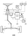
- a steering shaft (column shaft, handle shaft) 2 of a handle (steering wheel) 1 is a reduction gear (worm gear and worm) 3 constituting a reduction mechanism
- the universal joints 4a and 4b, the pinion rack mechanism 5, the tie rods 6a and 6b are connected to the steering wheels 8L and 8R via the hub units 7a and 7b.
- a torsion bar is inserted in the steering shaft 2, and a steering angle sensor 14 for detecting the steering angle ⁇ of the steering wheel 1 by a twist angle of the torsion bar and a torque sensor 10 for detecting the steering torque Th are provided.
- a motor 20 that assists the steering force of the handle 1 is connected to the steering shaft 2 via the reduction gear 3.
- the control unit (ECU) 30 that controls the electric power steering apparatus is supplied with electric power from the battery 13 and also receives an ignition key signal via the ignition key 11.
- the control unit 30 calculates a current command value for assist control based on the steering torque Th detected by the torque sensor 10 and the vehicle speed Vel detected by the vehicle speed sensor 12, and a voltage obtained by compensating the current command value.
- the current supplied to the motor 20 is controlled by the control value Vref.
- the vehicle speed Vel can also be received from a CAN (Controller Area Network) or the like.
- the control unit 30 is connected to a CAN (Controller Area Network) 40 that transmits and receives various types of vehicle information, and the vehicle speed Vel can also be received from the CAN 40.
- the control unit 30 can be connected to a non-CAN 41 that exchanges communications, analog / digital signals, radio waves, and the like other than the CAN 40.
- the control unit 30 is mainly composed of a CPU (including an MPU, MCU, etc.).
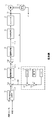
- FIG. 2 shows general functions executed by a program inside the CPU.
- the steering torque Th detected by the torque sensor 10 and the vehicle speed Vel detected by the vehicle speed sensor 12 are a current command for calculating a current command value Iref1.
- the value is input to the value calculation unit 31.
- the current command value calculation unit 31 calculates a current command value Iref1, which is a control target value of the current supplied to the motor 20, using an assist map or the like based on the input steering torque Th and vehicle speed Vel.
- the inverter 37 is composed of an FET bridge circuit as a semiconductor switching element.
- a rotation sensor 21 such as a resolver is connected to the motor 20, and a motor rotation angle ⁇ is output from the rotation sensor 21.
- the compensation signal CM from the compensation signal generation unit 34 is added to the addition unit 32A, and the compensation of the steering system system is performed by the addition of the compensation signal CM, thereby improving the convergence and inertia characteristics.
- the compensation signal generation unit 34 adds the self-aligning torque (SAT) 343 and the inertia 342 by the addition unit 344, and further adds the convergence 341 to the addition result by the addition unit 345, and compensates the addition result of the addition unit 345.
- the signal CM is used.
- torque sensors and angle sensors may be multiplexed and mounted in recent years due to demands for improved reliability and functional redundancy.
- the steering shaft and the motor shaft of the electric power steering device are connected via a speed reduction mechanism such as a worm gear.
- angle sensors are multiplexed, that is, two angle sensors are mounted on the steering shaft and the motor shaft, respectively, and if one system fails, it is conceivable to back up with the remaining one system.
- the mechanism system and the steering system including the speed reduction mechanism are nonlinear elements such as friction and backlash, elastic coupling of the motor output shaft, preload on the gear surface of the worm wheel and worm, and lubrication grease of the speed reduction mechanism. Therefore, the angle between the steering shaft and the motor shaft is different, and an angle error occurs. For this reason, even if one of the angle sensors fails, the other angle sensor cannot be immediately backed up (substitute for failure).
- Patent Document 1 discloses a method for measuring torque for a vehicle having an electromechanical steering system and is considered as a backup for a torque sensor.
- the overall configuration is an electromechanical steering apparatus including an input shaft portion and an output shaft portion connected to a drive steering mechanism, and steering means connected via a torsion bar having a servo motor.
- the configuration is an electromechanical steering device (digital circuit or analog circuit) that detects torque from the relative rotational displacement between the input shaft portion and the output shaft portion of the drive steering mechanism, but the steering angle ( ⁇ ) sensor
- the sensor for detecting the virtual torque is formed by the two inputs of the output and the rotation angle of the servo motor, and the steering torque is determined from the virtual torque.
- Patent Document 2 Japanese Patent Laid-Open No. 2005-274484
- a redundant system is configured by mounting a plurality (three) of steering angle sensors.
- Patent Document 1 as a backup system, a backup of a steering angle sensor can be backed up by rotor rotation information of a servo motor, but mutual failure diagnosis and backup for both sensors are possible. Is impossible. Further, in the example of Patent Document 2, since the periphery of the steering system is enlarged, there is a problem that the vehicle mountability of the apparatus is deteriorated and the cost is generally increased.
- the present invention has been made under the circumstances described above, and the object of the present invention is to determine the motor shaft angle and the steering shaft angle (pinion side) while learning the nonlinear elements of the mechanism system including the speed reduction mechanism and the steering system.
- An object of the present invention is to provide an inexpensive and high-performance electric power steering apparatus capable of performing high-precision estimation and backing up both angle sensors by using estimated angles of both angle sensors.
- learning of nonlinear elements of the mechanical system and steering system is divided into static characteristics, dynamic characteristics, and delay factors.
- static characteristics only, static characteristics + dynamic characteristics, static characteristics + dynamic characteristics.
- static characteristics + delay Provides a learning form that takes into account the case of characteristics + delay, can handle steering, can handle a wide range from slow to slow steering to high-speed steering, and further to environmental changes such as temperature and aging An electric power steering device that can also be used.
- a motor for assisting control of a steering system of a vehicle and a steering shaft are connected by a speed reduction mechanism, a first angle sensor for detecting a steering shaft angle of the steering shaft, and a first angle sensor for detecting a motor shaft angle of the motor.
- the electric power steering apparatus comprising a two-angle sensor, wherein the object of the present invention is to provide the reduction mechanism based on the measured angle of the first angle sensor, the measured angle of the second angle sensor, the motor torque, and the motor angular velocity.
- the compensation value map is obtained by repeatedly learning the characteristics of the non-linear elements, and the steering shaft angle and the motor shaft angle are estimated using the compensation value map.
- a motor for assisting control of a vehicle steering system and a steering shaft are connected by a speed reduction mechanism, a first angle sensor for detecting a steering shaft angle on the pinion side of the steering shaft, and a motor shaft of the motor.
- the present invention relates to an electric power steering apparatus including a second angle sensor that detects an angle and a current detection unit that detects a motor current of the motor.
- the object of the present invention is to provide a motor torque based on the motor current, and a steering shaft angle.
- Stearin used to estimate the steering shaft estimated angle It is accomplished by equipped with a shaft angle estimator, and a motor shaft angle estimator for estimating the motor shaft estimated angle by using the compensation value map and the steering shaft angle.
- a compensation value map is obtained while learning a non-linear element of a mechanism system and a steering system including a speed reduction mechanism as necessary, and a motor shaft angle and a steering shaft are calculated based on the compensation value map.
- the angle (pinion side) is estimated with high accuracy, and when one of the angle sensors malfunctions (including abnormality), both angle sensors can be backed up with each other.
- the number of sensors can be reduced by one.
- the angle sensor needs to be a triple system as disclosed in Patent Document 2, but it can be configured by a double system by using an estimated angle. It is.
- the present invention relates to friction and backlash of a mechanical system including a speed reduction mechanism and a steering system, elastic coupling of a motor output shaft, preload on a gear surface of a worm wheel and a worm, lubrication grease of a gear portion, contact condition of a gear surface ( While learning non-linear elements such as flexure as necessary, the angle of the motor shaft and the angle of the steering shaft (pinion side) are estimated with high accuracy, and the angle of one of the angles is estimated using the estimated angles of both angle sensors. When the sensor is faulty (hereinafter, including “abnormal”), the other angle sensor is backed up and the assist control is continued.
- the backup logic of both angle sensors is common, and the compensation value map of nonlinear compensation identified by learning is stored in a non-volatile memory such as EEPROM, so that the angle sensor is backed up immediately even after engine restart. Is possible.
- a nominal value based on experience is stored as an initial value in a nonvolatile memory such as EEPROM at the time of product shipment, and the actual compensation value when the ignition key is turned on exceeds the approximate value range of the nominal value
- static characteristic learning, dynamic characteristic learning, and delay characteristic learning are performed.
- the nominal value is preliminarily tuned so as to adapt to the environment of the vehicle destination (exporting country, region, etc.) (mainly temperature and humidity data depending on the local climate).
- accurate synchronization may be obtained by giving a time stamp each time a detection signal is received from each sensor, the angle error may be suppressed, and the steering speed at which steering angle detection is established may be increased (for example, special No. 2014-210471).
- the time stamp is synchronized when the detection cycle (for example, 500 ⁇ s) of the angle sensor attached to the steering shaft is different from the detection cycle (for example, 250 ⁇ s) of the resolver or MR sensor attached to the motor shaft. This is particularly effective in increasing the detection accuracy.
- the steering side angle sensor 63 on the steering wheel side of the steering shaft 61 and the pinion of the steering shaft 61.
- a pinion side angle sensor 64 is provided on the side, and a steering shaft angle Ap is output from the pinion side angle sensor 64.
- the steering shaft 61 is connected to a motor 66 via a speed reduction mechanism 65 such as a worm gear.
- the motor 66 detects a motor shaft angle sensor 67 (for example, a resolver or MR sensor) that detects a motor shaft angle Am and a motor current Im.
- a motor current detector (not shown) is provided.
- an elastic coupling (not shown) is provided at a connecting portion between the motor shaft and the speed reduction mechanism 65.
- one angle sensor (64, 67) is mounted on each of the steering shaft (pinion side) 61 and the motor shaft, and when one of the angle sensors fails, the detection angle of one of the angle sensors is used. Let us consider backing up the other angle sensor and continuing the assist control.
- the steering shaft angle Ap from the pinion side angle sensor 64, the motor shaft angle Am from the motor shaft angle sensor 67, and the motor current Im from the motor current detector are input to a control unit (ECU) 100.
- ECU control unit
- the detection angle is also output from the handle side angle sensor 63, but the description is omitted because it is not directly related to the present invention.
- the rotating shafts of the steering shaft 61 and the motor 66 are connected via a speed reduction mechanism 65 composed of a worm and a worm gear, but the mechanism system and the steering system including the speed reduction mechanism 65 include many nonlinear elements. That is, the mechanism system and the steering system include friction and backlash, elastic coupling of the motor output shaft, preload on the gear surface of the worm wheel and worm, lubrication grease of the gear portion, contact condition of the gear surface (deflection) Therefore, when one angle sensor fails, it cannot be backed up simply by replacing the detected value of the other angle sensor. Therefore, in the present invention, the output angle of the other angle sensor is estimated by repeatedly learning the nonlinear elements of the mechanism system and the steering system including the speed reduction mechanism 65.
- a configuration example of a control unit (ECU) 100 that performs such a function is shown in FIG.
- the motor current Im is input to the motor torque calculation unit 110, the calculated motor torque Tm is input to the nonlinear learning logic unit 130 of the nonlinear element, the motor shaft angle Am is input to the motor angular velocity calculation unit 120, and the calculated motor The angular velocity ⁇ m is input to the nonlinear learning logic unit 130 of the nonlinear element.
- the angle compensation value MP calculated by the nonlinear learning logic unit 130 of the nonlinear element is input to the steering shaft angle estimation unit 180 and the motor shaft angle estimation unit 190.
- the pinion side steering shaft angle Ap is input to the nonlinear learning logic unit 130 of the nonlinear element and also input to the motor shaft angle estimation unit 190.
- the motor shaft angle Am is input to the motor angular velocity calculation unit 120 and also input to the nonlinear learning logic unit 130 of the nonlinear element and the steering shaft angle estimation unit 180.
- the steering shaft angle estimation unit 180 outputs a steering shaft estimation angle SSe
- the motor shaft angle estimation unit 190 outputs a motor shaft estimation angle MSe.
- the angle sensor is a double system, and the estimated angle estimated is necessary. (1-1).
- the sensor configuration is such that the steering shaft angle sensor is a dual system (pinion side angle sensor 64-1 (steering shaft angle Ap1), 64-2 (steering shaft angle Ap2)) and the steering shaft estimated angle SSe. Is used.
- the failure diagnosis is performed by majority using the steering shaft angles Ap1 and Ap2 and the estimated steering shaft angle SSe.
- the pinion side angle sensor 64-1 (steering shaft angle Ap1) fails, the pinion side angle sensor 64-2 Is backed up (assist control is continued) using the steering shaft angle Ap2. (1-2).
- the motor shaft angle sensor is a dual system (motor shaft angle sensor 67-1 (motor shaft angle Am1), 67-2 (motor shaft angle Am2)), and motor shaft estimated angle MSe. Is used.
- the failure diagnosis is performed by a majority decision based on the motor shaft angles Am1 and Am2 and the motor shaft estimated angle MSe.
- the motor shaft angle sensor 67-1 (motor shaft angle Am1) fails, the motor shaft angle sensor 67-2 Is backed up (continues assist control) using the motor shaft angle Am2.
- the sensor configuration is the steering shaft angle sensor 64 (steering shaft angle Ap) of the steering shaft and the estimated steering shaft angle SSe, and the failure diagnosis is performed by comparing the steering shaft angle Ap and the estimated steering shaft angle SSe. If the steering shaft angle sensor 64 fails, the assist control is stopped.
- the sensor configuration is the motor shaft angle sensor 67 (motor shaft angle Am) of the motor shaft and the motor shaft estimated angle MSe, and the failure diagnosis is performed by comparing the motor shaft angle Am and the motor shaft estimated angle MSe. If the motor shaft angle sensor 67 fails, the assist control is stopped.
- the angle estimation in the steering shaft angle estimator 180 and the motor shaft angle estimator 190 can be broadly divided into two types: static characteristic compensation and dynamic characteristic compensation.
- Static characteristic compensation includes static angle compensation when the steering wheel is held, and when driving a car, temporarily stopping at an intersection, slowly checking safety and turning right or left.
- [Deg / s] Static characteristic map that is an angle compensation of dynamic characteristics during slow steering by slowly turning the steering wheel and that receives motor torque Tm (or noise-removed motor torque Tma that has passed through a low-pass filter (LPF)) as an input.
- LPF low-pass filter
- the dynamic characteristic compensation is angle compensation when the steering wheel is steered at a certain speed (50 [deg / s]) or more, such as when a person jumps out and suddenly turns the steering wheel, and the motor angular velocity ⁇ m.
- the compensation value CMd of the entire dynamic characteristic is calculated in consideration of the delay time corresponding to the motor torque Tm (noise-removed motor torque Tma) to the dynamic characteristic compensation value CMy based on the dynamic characteristic map.
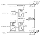
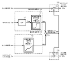
- FIG. 5 shows a configuration example (first embodiment) of a nonlinear learning logic unit 130 for nonlinear elements, a steering shaft angle estimation unit 180, and a motor shaft angle estimation unit 190.
- the nonlinear learning logic unit 130 for nonlinear elements includes: The static characteristic compensation unit 140 that calculates the compensation value CMs, the dynamic characteristic compensation unit 150 that calculates the compensation value CMd, and the addition unit 131 that adds the compensation values CMs and CMd and outputs the angle compensation value MP. ing.
- the static characteristic compensation unit 140 receives a low-pass filter (LPF) 141 that receives a motor torque Tm, and a noise-removed motor torque Tma from which high-frequency noise from the LPF 141 has been removed, and outputs a compensation value CMs. And a static characteristic map (learning completion) 142.
- the LPF 141 is necessary for preventing erroneous learning.
- the motor torque Tm is the current flowing through the motor itself.
- the motor current is mixed with ripple current, white noise, harmonics, etc. If the LPF process is not performed, the noisy part (peak) Sampling (for example, every 250 ⁇ s) may cause the static characteristic map 142 to be distorted. Therefore, an LPF with a cutoff frequency of 20 to 30 Hz is used.
- the dynamic characteristic compensator 150 receives a motor angular velocity ⁇ m and outputs a compensation value CMy, and a nonlinear element dynamic characteristic map 151 and noise from the compensation values CMy and LPF 141 output from the nonlinear element dynamic characteristic map 151. It comprises a non-linear element delay characteristic map (learning completion) 152 for inputting the removed motor torque Tma and outputting a compensation value CMd.
- the compensation values CMs and CMd are added by the adding unit 131, and the added value is output as a final angle compensation value MP (a compensation value map during learning).
- the angle compensation value MP is subtracted and input to the subtractor 181 of the steering shaft angle estimator 180 and added to the adder 191 of the motor shaft angle estimator 190.
- the subtraction unit 181 subtracts the angle compensation value MP from the motor shaft angle Am and outputs the steering shaft estimated angle SSe, and the addition unit 191 adds the steering shaft angle Ap and the angle compensation value MP to calculate the motor shaft estimated angle MSe. Is output.
- the angle compensation value MP is an angle difference between the static characteristic compensator 140 and the dynamic characteristic compensator 150.
- the static characteristic compensator 140 and the dynamic characteristic compensator 150 include a motor torque Tm and a motor angular velocity ⁇ m as a motor reference. Therefore, the angle compensation value MP is subtracted and input to the steering shaft angle estimator 180 and added to the motor shaft angle estimator 190.
- the diagnosis is performed according to the following formula 1, and if the formula 1 is satisfied, the learning is terminated. If the formula 1 is not satisfied, the learning is repeated a predetermined number of times (for example, twice).
- Equation 1 it is determined whether the absolute value of the difference between the steering shaft estimated angle SSe and the steering shaft angle Ap is within the allowable range ⁇ 1, and the absolute value of the difference between the motor shaft estimated angle MSe and the motor shaft angle Am is It is determined whether it is within the allowable range ⁇ 2.
- Equation 1 SSe-Ap
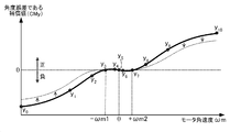
- the non-linear element dynamic characteristic map 151 is a characteristic in which the compensation value (CMy), which is an angular error, gradually increases nonlinearly as the motor angular velocity ⁇ m increases from 0 to the positive and negative directions.
- the angular velocity is in the range of ⁇ m1 to + ⁇ m2 (for example, 50 [deg / s]), that is, substantially flat characteristics in the vicinity of 0, and the flat portion can be covered with static characteristics. Since the viscosity decreases as the temperature increases, the compensation value also decreases as shown by the broken line.
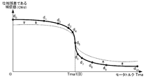
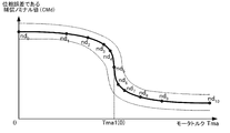
- the delay characteristic map 152 of the nonlinear element is a characteristic in which the compensation value (CMd) as a phase error gradually decreases nonlinearly as the motor torque Tma from the LPF 141 increases. In the vicinity of Tma1 (0), it decreases rapidly and finally converges to almost zero. Since the viscosity of the temperature characteristic of the delay characteristic map 152 also decreases as the temperature increases, the compensation value also decreases as shown by the broken line.
- each characteristic map corresponds to creation of the map.
- the map should be learned in a wide range (for example, from the vicinity of one (positive side) rack end to the vicinity of the other (negative side) rack end) with respect to the horizontal axis (motor torque Tm, motor angular velocity ⁇ m, motor torque Tma).
- the number of points on the map depends on the capacity of the RAM and ROM of the microcomputer and the calculation speed of the CPU, but cannot be determined, but learning is completed when a certain range is covered with respect to the horizontal axis.
- the horizontal axis is divided into 10 parts, and when 11 points are learned, the process is completed.
- FIGS. 9 to 11 Since learning data cannot be acquired at the time of product shipment, nominal values based on experience as shown in FIGS. 9 to 11 are stored in advance in a nonvolatile memory such as an EEPROM, and approximate to the nominal values indicated by broken lines. Each learning is performed when out of the value range.
- a nonvolatile memory such as an EEPROM
- FIG. 9 is a diagram showing a setting example of the nominal values (ns 0 to ns 10 ) of the static characteristic map of the nonlinear element, and the broken line shows an approximate value range for determining whether or not learning is necessary.
- FIG. 9 is a diagram showing a setting example of the nominal values (ns 0 to ns 10 ) of the static characteristic map of the nonlinear element, and the broken line shows an approximate value range for determining whether or not learning is necessary.
- FIG. 10 is a diagram showing a setting example of nominal values (ny 0 to ny 10 ) of the dynamic characteristic map of the nonlinear element, and the broken line shows an approximate value range for determining whether or not learning is necessary.
- FIG. 11 is a diagram showing an example of setting the nominal values (nd 0 to nd 10 ) of the delay characteristic map of the nonlinear element, and the broken line shows an approximate value range for determining whether or not learning is necessary.
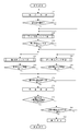
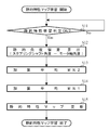
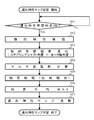
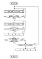
- FIG. 12 shows an overall operation example (first embodiment) in which dynamic characteristics are learned after learning of static characteristics, delay learning is further performed, and angle estimation is performed based on these learning results. Will be described with reference to FIG.
- step S1 when the ignition key is turned on, an angle is detected (step S1), and it is determined whether or not the calculated compensation value is within the approximate value range of the nominal value shown in FIG. 9 (step S2).
- the compensation values A1 and A2 are outside the range, and the compensation values B1 and B2 are within the range.
- step S10 the static characteristic map 142 of the nonlinear element is learned (step S10), and the learning is continued until the learning is completed (step S20).
- the static characteristic map is sufficiently learned for the motor torque region of the electric power steering device (for example, FIG. 6), the learning is completed.
- step S30 the learning of the dynamic characteristic map 151 of the nonlinear element
- step S50 the learning of the delay characteristic map 152 of the nonlinear element
- step S30 For the learning of the dynamic characteristic map 151 of the nonlinear element (step S30) and the learning of the delay characteristic map 152 of the nonlinear element (step S50), the inside and outside of the approximate value range of the nominal value shown in FIGS. Learning is performed when the compensation value is outside the approximate value range, but learning may be performed without this determination. In FIG. 12, the determination operation is omitted.
- the delay characteristic map 152 of the nonlinear element is learned. Learning of the nonlinear element dynamic characteristic map 151 (step S30) is continued until learning is completed (for example, FIG. 7) (step S40), and learning of the nonlinear element delay characteristic map 152 is completed (step S50). For example, it is continued until FIG. 8) (step S60).
- the dynamic characteristic map is sufficiently learned for the motor angular velocity ⁇ region of the electric power steering apparatus, the learning is completed.
- the delay characteristic map is sufficiently learned for the motor torque Tma region, the learning is completed.
- the compensation value map is created.
- Compensation value CMs from unit 140 and compensation value CMd from dynamic characteristic compensation unit 150 are added by addition unit 131 to calculate angle compensation value MP, and an estimated angle is estimated based on angle compensation value MP (step S71).
- the steering shaft estimated angle SSe is obtained by subtracting the angle compensation value MP from the motor shaft angle Am, and the motor shaft estimated angle MSe is obtained by adding the steering shaft angle Ap and the angle compensation value MP.
- step S72 whether or not the error (absolute value) between the estimated angle and the actually measured value is within the allowable range ⁇ is diagnosed according to the above equation 1 (step S72). If it is greater than N, it is determined whether or not it is the Nth time (for example, the third time) (step S80), and if it is less than the Nth time, the process returns to step S10 and the above operation is repeated.
- the Nth time for example, the third time
- step S80 when it is determined as the Nth time, it is determined that the steering system or the sensor system is broken (step S81). Note that the setting of the number N of repetitions of step S80 can be changed as appropriate.
- the accuracy of the steering shaft estimated angle SSe and the motor shaft estimated angle MSe can be improved, and it is possible to cope with changes in the surrounding environment such as temperature and aging deterioration of mechanical parts.
- a temperature sensor may be provided separately to correct the value of each map according to the detected temperature.
- the input signals necessary for each learning are a motor torque Tm, a motor angular acceleration ⁇ m, a motor angular velocity ⁇ m, a motor shaft angle Am, and a steering shaft angle Ap.
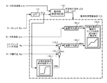
- step S10 learning of the static characteristic map 142 of the nonlinear element in step S10 will be described.
- the static characteristic map 142 of the nonlinear element is a compensation value CMs in which the horizontal axis represents the motor torque Tm and the vertical axis represents the angular deviation between the motor shaft angle Am and the steering shaft angle Ap.
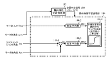
- the configuration of the static characteristic map 142 of the non-linear element includes, for example, a static characteristic learning determination unit 143 and a static characteristic learning logic unit 144 as shown in FIG.
- the motor angular velocity ⁇ m is input to the static characteristic learning determination unit 143, and the static characteristic learning determination unit 143 outputs a learning determination signal LD1 according to the determination described later (ON / OFF).
- the static characteristic learning logic unit 144 includes a subtraction unit 144-1, addition averaging units 144-1 and 144-2, and a nonlinear element staticity map creation unit 144-4.
- the noise-removed motor torque Tma from which noise has been removed from the LPF 141 is input to the averaging unit 144-2, and the steering shaft angle Ap and the motor shaft angle Am are input to the subtracting unit 144-1. Is input to the unit 144-3.
- the learning determination signal LD1 is input to the static characteristic learning logic unit 144, and the addition average values MN1 and MN2 obtained by the addition average units 144-1 and 144-2 are input to the nonlinear element static characteristic map generation unit 144-4. Entered.
- Static characteristic learning of the static characteristic learning logic unit 144 is performed when the steering wheel is in the steering state or when the steering is slowed down to 5 [deg / s] or less (the motor angular velocity ⁇ m is almost zero), that is, static characteristic learning.
- the determination unit 143 determines that the motor angular velocity ⁇ m has become substantially zero and turns on the learning determination signal LD1
- learning is performed when ON of the learning determination signal LD1 is input to the static characteristic learning logic unit 144.
- Starts step S11).
- the deviation Dp between the steering shaft angle Ap and the motor shaft angle Am is calculated by the subtraction unit 144-1 (step S 12), and the deviation Dp is input to the addition averaging unit 144-3.
- the addition average value MN2 is calculated at -3 (step S13). Further, the noise-removed motor torque Tma from the LPF 141 is also input to the addition averaging unit 144-2, and the addition average unit 144-2 calculates the addition average value MN1 (step S14). The calculation order of the addition average values MN1 and MN2 may be reversed.
- the addition average values MN1 and MN2 are input to the nonlinear element static characteristic map creating unit 144-4 (corresponding to the nonlinear element static characteristic map 142 of FIG. 5), and the nonlinear element is calculated using a calculation such as a sequential least square method.
- the static characteristic map 142 is updated (step S15).
- the static characteristic map 142 of the nonlinear element is updated by using the calculation such as the sequential least square method, and the motor torque region of the electric power steering device is updated.
- the learning is completed when the static characteristic map is sufficiently learned.
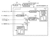
- step S30 learning of the dynamic characteristic map in step S30 will be described.
- the horizontal axis represents the motor angular velocity ⁇ m
- the vertical axis represents the compensation value CMy which is the angular deviation of the motor shaft angle Ams (after static characteristic compensation) and the steering shaft angle Ap.
- the configuration of the dynamic characteristic map 151 of the nonlinear element is, for example, FIG.
- the motor angular acceleration ⁇ m is input to the dynamic characteristic learning determining unit 145, and the motor torque Tm is input to the dynamic characteristic learning determining unit 145 via the LPF 141 and also input to the static characteristic map 146-1 of the nonlinear element.
- the dynamic characteristic learning determination unit 145 outputs the learning determination signal LD2 under a predetermined condition (a state where the motor angular acceleration ⁇ m is substantially zero and the motor torque Tm (Tma) is large to some extent) (ON / OFF).
- the dynamic characteristic learning logic unit 146 also includes a non-linear element static characteristic map 146-1, an addition unit 146-2, a subtraction unit 146-3, addition averaging units 146-4 and 144-5, and a non-linear element dynamic characteristic map.
- the generation unit 146-6 (corresponding to the dynamic characteristic map 151 of the nonlinear element in FIG. 5) is configured.
- the motor angular velocity ⁇ m is input to the addition averaging unit 146-4
- the steering shaft angle Ap is input to the subtraction unit 146-3
- the motor shaft angle Am is input to the addition unit 146-2.
- Compensation value CMs from the static characteristic map 146-1 of the nonlinear element is input to the addition unit 146-2, and the addition value (motor shaft angle after static characteristic compensation) Ams is subtracted and input to the subtraction unit 146-3. Is done.
- the learning determination signal LD2 is input to the dynamic characteristic learning logic unit 146, and the addition average values MN3 and MN4 obtained by the addition average units 146-4 and 146-5 are input to the dynamic characteristic map generation unit 146-6 of the nonlinear element. Is done.
- the dynamic characteristic learning of the dynamic characteristic learning logic unit 146 is learned when the motor angular acceleration ⁇ m is almost zero and the worm gear and the motor gear are firmly meshed (the noise-removed motor torque Tma from the LPF 141 is large to some extent).
- the determination signal LD2 is turned on and input to the dynamic characteristic learning logic unit 146, and learning starts from this time (step S31).
- the noise-removed motor torque Tma from the LPF 141 is input to the static characteristic map 146-1 of the nonlinear element, and static characteristic compensation is performed (step S32).
- the compensation value CMs for static characteristic compensation is input to the adder 146-2, the added value Ams with the motor shaft angle Am after static characteristic compensation is obtained, and the added value Ams is subtracted and input to the subtractor 146-3.
- An average value MN4 is calculated (step S34).
- the motor angular velocity ⁇ m is also input to the addition averaging unit 146-4, and the addition average value MN3 is calculated by the addition averaging unit 146-4 (step S35).
- the calculation order of the addition average values MN3 and MN4 may be reversed.
- the addition average values MN3 and MN4 are input to the nonlinear element dynamic characteristic map creation unit 146-6, and when the learning condition is continued for a certain period of time, the nonlinear element dynamic characteristic map 151 is updated by using a calculation such as a sequential least square method. (Step S36).
- step S50 the learning of the delay characteristic map in step S50 will be described.
- the horizontal axis represents the motor torque Tma
- the vertical axis represents the compensation value CMd which is the phase deviation between the motor shaft angle Ams (after static characteristic compensation) and the steering shaft angle Ap.
- the configuration of the delay characteristic map is, for example, FIG.
- the noise-removed motor torque Tma having passed through the LPF 141 is input to the delay characteristic learning determination unit 147 and also to the nonlinear element static characteristic map 148-1.
- the delay characteristic learning determination unit 147 outputs a learning determination signal LD3 (ON / OFF) under a predetermined condition (when the motor torque Tm (Tma) becomes smaller than a predetermined value), and the learning determination signal LD3 is a delay characteristic learning logic. Is input to the unit 148.
- the delay characteristic learning logic unit 148 includes a non-linear element static characteristic map 148-1 (146-1 in FIG. 15), an adder 148-2, a subtractor 148-3, an addition averaging unit 148-5, and a multi delay unit 148.
- the motor torque Tm is input to the addition averaging unit 148-5, the motor angular velocity ⁇ m is input to the multi delay unit 148-4, and the multi delay output MD is input to the cross correlation unit 148-6.
- the steering shaft angle Ap is added to the subtraction unit 148-3, and the motor shaft angle Am is input to the addition unit 148-2.
- Compensation value CMs from the static characteristic map 148-1 of the nonlinear element is input to the addition unit 148-2, and the addition value (motor shaft angle after static characteristic compensation) Ams is subtracted into the subtraction unit 148-3. Is done.
- the deviation Dd calculated by the subtraction unit 148-3 is input to the cross-correlation unit 148-6.
- the cross-correlation unit 148-6 performs cross-correlation processing based on the multi-delay output MD and the deviation Dd from the multi-delay unit 148-4 and searches for a delay time with the highest correlation. Since cross-correlation analyzes the similarity between two input signals, a certain analysis time is required.
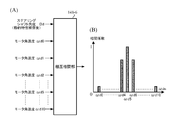
- FIG. 18 shows an operation example of the multi-delay unit 148-4.
- the multi-delay unit 148-4 is delayed by a predetermined delay time by each delay unit (Z ⁇ 1 ) with respect to the input of the motor angular velocity ⁇ m.
- Motor angular velocities ⁇ d0, ⁇ d1,... ⁇ d10 are output.
- the multi-delay motor angular velocity MD ( ⁇ d0 to ⁇ d10) output from the multi-delay unit 148-4 is input to the cross-correlation unit 148-6 together with the steering shaft angle (after static characteristic compensation) Dd, and the cross-correlation unit 148-6 19 calculates a correlation function of the steering shaft angle Dd as a reference signal and the multi-delay motor angular velocity MD ( ⁇ d0 to ⁇ d10) from the multi-delay unit 148-4 as shown in FIG. Reflect the delay time on the map.
- the learning determination signal LD3 is input to the delay characteristic learning logic unit 148, and the addition average value MN5 obtained by the addition average unit 148-5 and the cross correlation value ML output from the cross correlation unit 148-6 are also nonlinear element delay characteristics.
- the data is input to the map creation unit 148-7.
- the delay characteristic learning logic unit 148 performs delay characteristic learning according to the above conditions, when the motor torque Tma (or Tm) is reduced to a predetermined value or less, and turns on the learning determination signal LD3 to the delay characteristic learning logic unit 148. The learning is started from this time (step S51).
- the noise-removed motor torque Tma from the LPF 141 is input to the non-linear element static characteristic map 148-1, and the static characteristic compensation by the non-linear element static characteristic map 148-1 is performed.
- the compensation value CMs for static characteristic compensation is input to the addition unit 148-2, and the addition value (motor shaft angle after static characteristic compensation) Ams with the motor shaft angle Am is subtracted and input to the subtraction unit 148-3.
- the deviation Dd from the steering shaft Ap is calculated by the section 148-3 (step S53), and the deviation Dd is input to the cross-correlation section 148-6.
- the motor angular velocity ⁇ m is input to the multi-delay unit 148-4, and a plurality of multi-delay motor angular velocities MD ( ⁇ d0 to ⁇ d10) having different delay times are calculated (step S54).
- 148-6 is input to perform cross-correlation processing (step S55).
- the cross-correlation unit 148-6 searches for a delay time having the largest correlation from a plurality of multi-delay motor angular velocities having different delay amounts, and outputs a correlation coefficient ML.
- the motor torque Tma is input to the addition average unit 148-5, and the addition average value MN5 is calculated (step S56).
- the calculation order of the addition average value MN5 and the correlation coefficient ML may be reversed.
- the addition average value MN5 and the correlation coefficient ML are input to the delay characteristic map creation unit 148-7 of the nonlinear element, and when the learning condition is continued for a certain period of time, the delay characteristic map 152 is updated using a calculation such as a sequential least square method. (Step S57).
- the delay characteristic map is sufficiently learned with respect to the motor torque region of the electric power steering apparatus, the learning is completed.
- the static characteristic map 142 in FIG. 5 corresponds to the static characteristic map creating unit 144-4 in FIG. 13, and the dynamic characteristic map 151 in FIG. 5 is added to the dynamic characteristic map creating unit 146-6 in FIG.
- the delay characteristic map 152 in FIG. 5 corresponds to the delay characteristic map creation unit 148-7 in FIG.
- FIG. 5 is a map that has been learned, and FIGS. 13, 15, and 17 are maps that are being learned, and are given different reference numerals in this sense.
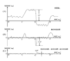
- the horizontal axis represents time
- the vertical axis represents the angle error (difference between motor shaft angle and steering shaft angle).
- the section from the time point t0 to the time point t1 shows a state of steering left and right at the center of the steering wheel.
- the section from the time point t1 to the time point t2 shows a state in which the steering wheel is turned to the vicinity of the left end and steered to the left and right.
- the section from time t2 to time t3 shows a state in which the steering wheel is turned to the vicinity of the right end and steered to the left and right, and after time t3, the steering wheel is returned to the center.
- the angular difference is large (2.5 °).
- the angle difference decreases (0.75 °). Furthermore, by adding dynamic characteristic compensation, as shown in FIG. 21 (C), the angular difference can be reduced (0.25 °) even for a fast-moving handle.
- the static characteristic, the dynamic characteristic, and the delay characteristic are compensated as shown in FIG. 5, but only the static characteristic compensation may be performed with the configuration shown in FIG. Second embodiment).
- the static characteristic compensator 140 that calculates the compensation value CMs inputs the low-pass filter (LPF) 141 that receives the motor torque Tm and the noise-removed motor torque Tma from which the high-frequency noise from the LPF 141 has been removed. And a static characteristic map (learning completion) 142 of a nonlinear element that outputs CMs (a compensation value map during learning).
- LPF low-pass filter
- the compensation value CMs is subtracted and input to the subtractor 181 and input to the adder 191.
- the subtractor 181 outputs the steering shaft estimated angle SSe
- the adder 191 outputs the motor shaft estimated angle MSe.
- the error absolute value
- learning is performed until the error is within the allowable range ⁇ . Is repeated and learning ends when it falls within the allowable range ⁇ .
- the number of points on the map depends on the capacity of the RAM and ROM of the microcomputer and the calculation speed of the CPU, but cannot be determined, but learning is completed when a certain range is covered with respect to the horizontal axis.
- the learning may be started by determining that the compensation value is outside the approximate value range of the nominal value shown in FIG.
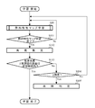
- the static characteristic map 142 of the nonlinear element is learned (step S10), and the learning is continued until the learning is completed (step S101).
- the static characteristic map is sufficiently learned for the motor torque region of the electric power steering device (for example, FIG. 6)
- the learning is completed.
- the compensation value map is created upon completion of learning of the static characteristic map 142 of the nonlinear element
- the estimated angle is estimated based on the compensation value CMs from the static characteristic compensation unit 140 (step S102).
- the steering shaft estimated angle SSe is obtained by subtracting the compensation value CMs from the motor shaft angle Am
- the motor shaft estimated angle MSe is obtained by adding the steering shaft angle Ap and the compensation value CMs.
- step S103 whether or not the error (absolute value) between the estimated angle and the actually measured value is within the allowable range ⁇ is diagnosed according to the above equation 1 (step S103). If it is greater than, for example, it is determined whether or not it is the third time (step S104), and if it is within the second time, the process returns to step S10 and the above operation is repeated.
- step S104 when it is determined as the third time, it is determined that the steering system or the sensor system is broken (step S105). Note that the setting of the number of repetitions of step S104 can be changed as appropriate.
- the accuracy of the steering shaft estimated angle SSe and the motor shaft estimated angle MSe can be improved, and it is possible to cope with changes in the surrounding environment such as temperature and aging deterioration of mechanical parts.
- a temperature sensor may be provided separately to correct the value of each map according to the detected temperature.
- the learning operation of the static characteristic map 142 of the nonlinear element in step S10 is the same as in FIG.
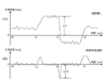
- the section from time t0 to time t1 shows a state of steering left and right at the center of the steering wheel.
- the section from the time point t1 to the time point t2 shows a state in which the steering wheel is turned to the vicinity of the left end and steered to the left and right.
- the section from time t2 to time t3 shows a state in which the steering wheel is turned to the vicinity of the right end and steered to the left and right, and after time t3, the steering wheel is returned to the center.
- the angular error is large when there is no compensation (2.5 °). However, as shown in FIG. On the other hand, the angle error decreases (0.75 °).
- FIG. 25 shows a configuration example of the third embodiment that performs compensation for static characteristics and dynamic characteristics (no delay characteristics), and the nonlinear learning logic unit 130 for nonlinear elements calculates the static characteristics for calculating the compensation value CMs.
- the compensation unit 140 includes a dynamic characteristic compensation unit 150 that calculates the compensation value CMy, and an addition unit 131 that adds the compensation values CMs and CMy to output the angle compensation value MP.
- the static characteristic compensation unit 140 receives a low-pass filter (LPF) 141 that receives a motor torque Tm, and a noise-removed motor torque Tma from which high-frequency noise from the LPF 141 has been removed, and outputs a compensation value CMs.
- LPF low-pass filter
- the dynamic characteristic compensation unit 150 includes a dynamic characteristic map 151 of a nonlinear element that inputs a motor angular velocity ⁇ m and outputs a compensation value CMy.
- the compensation values CMs and CMy are added by the adding unit 131, and the added value is output as a final angle compensation value MP (a compensation value map during learning).
- the angle compensation value MP is subtracted and input to the subtracting unit 181 and input to the adding unit 191 of the motor shaft angle estimating unit 190.
- the subtractor 181 outputs the steering shaft estimated angle SSe
- the adder 191 outputs the motor shaft estimated angle MSe. Diagnose whether the error (absolute value) between the estimated steering shaft angle SSe and the estimated motor shaft angle MSe and each measured value is within the allowable range ⁇ or not, and repeat learning until the error is within the allowable range ⁇ . The learning ends when it falls within the allowable range ⁇ .
- the static characteristic map 142 of the nonlinear element is the characteristic shown in FIG. 6, and the dynamic characteristic map 151 of the nonlinear element is the characteristic shown in FIG.
- each characteristic map (142, 151) corresponds to the creation of the map, and for estimating the angle of each part of the electric power steering apparatus, nonlinear factors such as friction and backlash of the mechanical system including the speed reduction mechanism 65 and the steering system It is desirable to compensate at least static characteristics for compensation, and to learn dynamic characteristics after learning static characteristics.
- each learning may be started by determining that the compensation value is outside the approximate value range of each nominal value shown in FIG. 9 and FIG.
- the static characteristic map 142 of the nonlinear element is learned (step S10), and is continued until the learning is completed (step S20).
- the learning is completed.
- the non-linear element characteristic map 151 is learned (step S30). Learning of the dynamic characteristic map 151 of the nonlinear element (step S30) is continued until learning is completed (for example, FIG. 7) (step S40).
- the dynamic characteristic map is sufficiently learned for the motor angular velocity region of the electric power steering apparatus, the learning is completed.
- step S110 The angle compensation value MP is calculated by adding in 131, and the estimated angle is estimated based on the angle compensation value MP (step S110).
- the steering shaft estimated angle SSe is obtained by subtracting the angle compensation value MP from the motor shaft angle Am, and the motor shaft estimated angle MSe is obtained by adding the steering shaft angle Ap and the angle compensation value MP.
- step S111 whether or not the error (absolute value) between the estimated angle and the actually measured value is within the allowable range ⁇ is diagnosed according to the above equation 1 (step S111). If it is greater than, for example, it is determined whether or not it is the third time (step S112), and if it is within the second time, the process returns to step S10 and the above operation is repeated.
- step S112 when it is determined as the third time, it is determined that the steering system or the sensor system is broken (step S113).
- the setting of the number of repetitions of step S112 can be changed as appropriate.
- the accuracy of the steering shaft estimated angle SSe and the motor shaft estimated angle MSe can be improved, and it is possible to cope with changes in the surrounding environment such as temperature and aging deterioration of mechanical parts.
- a temperature sensor may be provided separately to correct the value of each map according to the detected temperature.
- step S10 The learning operation of the non-linear element static characteristic map 142 in step S10 is the same as in FIG. 14, and the learning operation of the non-linear element dynamic characteristic map 151 in step S30 is the same as in FIG.
- the column type electric power steering apparatus has been described.
- the present invention can be similarly applied to a downstream type electric power steering apparatus.
Landscapes
- Engineering & Computer Science (AREA)
- Chemical & Material Sciences (AREA)
- Combustion & Propulsion (AREA)
- Transportation (AREA)
- Mechanical Engineering (AREA)
- Power Engineering (AREA)
- Physics & Mathematics (AREA)
- General Physics & Mathematics (AREA)
- Steering Control In Accordance With Driving Conditions (AREA)
- Power Steering Mechanism (AREA)
Abstract
Description
(1)故障診断及びバックアップを行う場合:
この場合には、角度センサを2重系とし、推定した推定角度が必要である。
(1-1).ステアリングシャフト角度の場合
センサ構成は、ステアリングシャフトの角度センサを2重系(ピニオン側角度センサ64-1(ステアリングシャフト角度Ap1),64-2(ステアリングシャフト角度Ap2))とし、ステアリングシャフト推定角度SSeを用いる。故障診断は、ステアリングシャフト角度Ap1及びAp2、ステアリングシャフト推定角度SSeの3つで多数決により行い、例えばピニオン側角度センサ64-1(ステアリングシャフト角度Ap1)が故障した場合、ピニオン側角度センサ64-2のステアリングシャフト角度Ap2を用いてバックアップ(アシスト制御継続)する。
(1-2).モータ軸角度の場合
センサ構成は、モータ軸の角度センサを2重系(モータ軸角度センサ67-1(モータ軸角度Am1),67-2(モータ軸角度Am2))とし、モータ軸推定角度MSeを用いる。故障診断は、モータ軸角度Am1及びAm2、モータ軸推定角度MSeの3つで多数決により行い、例えばモータ軸角度センサ67-1(モータ軸角度Am1)が故障した場合、モータ軸角度センサ67-2のモータ軸角度Am2を用いてバックアップ(アシスト制御継続)する。
(2)故障診断のみの場合:
この場合にはバックアップはなく、1つの角度センサと推定した推定角度が必要である。
(2-1).ステアリングシャフト角度の場合
センサ構成は、ステアリングシャフトのステアリングシャフト角度センサ64(ステアリングシャフト角度Ap)とステアリングシャフト推定角度SSeであり、故障診断は、ステアリングシャフト角度Apとステアリングシャフト推定角度SSeを比較して行い、ステアリングシャフト角度センサ64が故障した場合には、アシスト制御を停止する。
(2-2).モータ軸角度の場合
センサ構成は、モータ軸のモータ軸角度センサ67(モータ軸角度Am)とモータ軸推定角度MSeであり、故障診断は、モータ軸角度Amとモータ軸推定角度MSeを比較して行い、モータ軸角度センサ67が故障した場合には、アシスト制御を停止する。
(数1)
|SSe-Ap|≦ε1
|MSe-Am|≦ε2
なお、学習を繰り返しても、数1の両方又は一方が成立しない場合には、操舵系若しくはセンサ系のいずれか一方が故障乃至異常であると判定する。
2、61 ステアリングシャフト(コラム軸、ハンドル軸)
10 トルクセンサ
12 車速センサ
13 バッテリ
20、66 モータ
21 回転センサ
30、100 コントロールユニット(ECU)
62 トーションバー
63 ハンドル側角度センサ
64 ピニオン側角度センサ
65 減速機構
67 モータ軸角度センサ
110 モータトルク演算部
120 モータ角速度演算部
130 非線形要素の非線形学習論理部
140 静的特性補償部
141 ローパスフィルタ(LPF)
142 非線形要素の静的特性マップ
150 動特性補償部
151 非線形要素の動特性マップ
152 非線形要素の遅れ特性マップ
180 ステアリングシャフト角度推定部
190 モータ軸角度推定部
Claims (25)
- 車両の操舵系をアシスト制御するモータとステアリングシャフトとが減速機構により接続され、前記ステアリングシャフトのステアリングシャフト角度を検出する第1角度センサと、前記モータのモータ軸角度を検出する第2角度センサとを具備する電動パワーステアリング装置において、
前記第1角度センサの実測角度、前記第2角度センサの実測角度、モータトルク及びモータ角速度に基づき、前記減速機構を含む非線形要素の特性の学習を繰り返し行って補償値マップを求め、前記補償値マップを用いて前記ステアリングシャフト角度及び前記モータ軸角度を推定することを特徴とする電動パワーステアリング装置。 - 前記ステアリングシャフト角度の推定角度及び前記モータ軸の推定角度と、前記第1角度センサの実測角度及び前記第2角度センサの実測角度とを比較することにより、前記第1角度センサ及び前記第2角度センサの故障を相互に診断する診断機能を有する請求項1に記載の電動パワーステアリング装置。
- 前記診断機能により、前記第1角度センサ又は前記第2角度センサが故障であると判定された場合、前記モータ軸の推定角度又は前記ステアリングシャフト角度の推定角度に基づいて前記アシスト制御を継続するようになっている請求項2に記載の電動パワーステアリング装置。
- 前記学習は、ハンドルを保舵又は所定速度以下で緩慢操舵した場合の静的特性学習及び前記ハンドルを所定速度以上で操舵した場合の動特性学習で実施される請求項1乃至3のいずれかに記載の電動パワーステアリング装置。
- 前記第1角度センサの実測角度、前記第2角度センサの実測角度、前記モータトルク及び前記モータ角速度に基づく初期値が、予め格納されている各特性ノミナル値の近似値範囲外であるときに前記静的特性学習及び前記動特性学習を実施する請求項4に記載の電動パワーステアリング装置。
- 前記学習は、ハンドルを保舵又は所定速度以下で緩慢操舵した場合の静的特性学習で実施される請求項1乃至3のいずれかに記載の電動パワーステアリング装置。
- 前記第1角度センサの実測角度、前記第2角度センサの実測角度、前記モータトルク及び前記モータ角速度に基づく初期値が、予め格納されている静的特性ノミナル値の近似値範囲外であるときに前記静的特性学習を実施する請求項6に記載の電動パワーステアリング装置。
- 前記学習は、ハンドルを保舵又は所定速度以下で緩慢操舵した場合の静的特性学習、前記ハンドルを所定速度以上で操舵した場合の動特性学習及び遅れ特性学習で実施される請求項1乃至3のいずれかに記載の電動パワーステアリング装置。
- 前記第1角度センサの実測角度、前記第2角度センサの実測角度、前記モータトルク及び前記モータ角速度に基づく初期値が、予め格納されている各特性ノミナル値の近似値範囲外であるときに前記静的特性学習、前記動特性学習及び前記遅れ特性学習を実施する請求項8に記載の電動パワーステアリング装置。
- 前記ステアリングシャフト角度が、前記ステアリングシャフトのトーションバーに対してピニオン側の角度である請求項1乃至9のいずれかに記載の電動パワーステアリング装置。
- 前記比較を、前記ステアリングシャフト角度の推定角度及び前記モータ軸の推定角度と、前記第1角度センサの実測角度及び前記第2角度センサの実測角度との偏差が許容範囲内であるかによって行い、前記許容範囲外である動作を所定回数繰り返したときに、前記操舵系若しくはセンサ系の故障を判定する請求項2乃至10のいずれかに記載の電動パワーステアリング装置。
- 車両の操舵系をアシスト制御するモータとステアリングシャフトとが減速機構により接続され、前記ステアリングシャフトのピニオン側のステアリングシャフト角度を検出する第1角度センサと、前記モータのモータ軸角度を検出する第2角度センサと、前記モータのモータ電流を検出する電流検出部とを具備する電動パワーステアリング装置において、
前記モータ電流に基づくモータトルク、前記ステアリングシャフト角度、前記モータ軸角度に基づくモータ角速度により、前記減速機構を含む非線形要素の特性の学習を繰り返し行い、補償値マップを演算する非線形要素の非線形論理部と、
前記補償値マップ及び前記モータ軸角度を用いて前記ステアリングシャフト推定角度を推定するステアリングシャフト角度推定部と、
前記補償値マップ及び前記ステアリングシャフト角度を用いて前記モータ軸推定角度を推定するモータ軸角度推定部と、
を具備したことを特徴とする電動パワーステアリング装置。 - 前記非線形要素の非線形論理部が、
前記モータトルクに対する静的特性補償部と、前記モータ角速度に対する動特性補償部とで構成されている請求項12に記載の電動パワーステアリング装置。 - 前記静的特性補償部が第1補償値を出力し、前記動特性補償部が第2補償値を出力し、第1補償値及び第2補償値を加算して角度補償値を生成する請求項13に記載の電動パワーステアリング装置。
- 前記静的特性補償部が、
前記モータトルクを入力するLPFと、前記LPFからのノイズ除去済みモータトルクを入力する非線形要素の静的特性マップとで構成されている請求項13又は14に記載の電動パワーステアリング装置。 - 前記動特性補償部が、
前記モータ角速度を入力する非線形要素の動特性マップと、前記ノイズ除去済みモータトルク及び前記非線形要素の動特性マップからの第1補償値を入力する非線形要素の遅れ特性マップとで構成されている請求項13乃至15のいずれかに記載の電動パワーステアリング装置。 - 前記非線形要素の静的特性マップが、
前記モータ角速度に基づいて第1学習判定信号を出力する静的特性学習判定部と、前記第1学習判定信号、前記モータトルク、前記ステアリングシャフト角度及び前記モータ軸角度を入力する静的特性学習論理部とで構成されている請求項15に記載の電動パワーステアリング装置。 - 前記静的特性学習論理部が、
前記モータトルクを入力する第1加算平均部と、前記ステアリングシャフト角度及び前記モータ軸角度の偏差を入力する第2加算平均部と、前記第1加算平均部及び前記第2加算平均部からの第1加算平均値及び第2加算平均値を入力する非線形要素の静的特性マップ作成部とで構成されている請求項17に記載の電動パワーステアリング装置。 - 前記非線形要素の動特性マップが、
前記LPFと、モータ角加速度及び前記LPFからのモータトルクに基づいて第2学習判定信号を出力する動特性学習判定部と、前記第2学習判定信号、前記モータ角度、前記ステアリングシャフト角度及び前記モータ軸角度を入力する動特性学習論理部とで構成されている請求項16に記載の電動パワーステアリング装置。 - 前記動特性学習論理部が、
前記非線形要素の静的特性マップと、前記モータ角速度を入力する第3加算平均部と、前記モータ軸角度及び前記非線形要素の静的特性マップからの第3補償値の加算値と前記ステアリングシャフト角度の偏差を入力する第4加算平均部と、前記第3加算平均部及び前記第4加算平均部からの第3加算平均値及び第4加算平均値を入力する非線形要素の動特性マップ作成部とで構成されている請求項19に記載の電動パワーステアリング装置。 - 前記非線形要素の遅れ特性マップが、
前記ノイズ除去済みモータトルクに基づいて第3学習判定信号を出力する遅れ特性学習判定部と、前記第3学習判定信号、前記モータトルク、前記モータ角速度、前記ステアリングシャフト角度及び前記モータ軸角度を入力する遅れ特性学習論理部とで構成されている請求項16に記載の電動パワーステアリング装置。 - 前記遅れ特性学習論理部が、
前記非線形要素の静的特性マップと、
前記モータトルクを入力する第5加算平均部と、
前記モータ角速度を入力するマルチ遅延部と、
前記マルチ遅延部からのマルチ遅延モータ角速度を入力すると共に、前記モータ軸角度及び前記第3補償値の加算値と前記ステアリングシャフト角度の偏差を入力する相互相関部と、
前記第5加算平均部からの第5加算平均値、前記相互相関部からの相互相関値を入力する非線形要素の遅れ特性マップ作成部と、
で構成されている請求項21に記載の電動パワーステアリング装置。 - 前記マルチ遅延部が複数の遅延器で構成されており、前記モータ角速度を所定遅延時間ずる遅延させたマルチ遅延モータ角速度を出力するようになっている請求項22に記載の電動パワーステアリング装置。
- 前記相互相関部が、前記ステアリングシャフト角度を参照として、前記マルチ遅延モータ角速度の相関関数を計算し、相関の一番大きい前記マルチ遅延モータ角速度の遅延時間を前記非線形要素の遅れ特性マップ作成部に反映させるようになっている請求項23に記載の電動パワーステアリング装置。
- 前記学習を推定角度と実測角度の誤差が許容範囲内となるように行い、前記誤差が前記許容範囲外である動作を所定回数繰り返したときに、前記操舵系若しくはセンサ系の故障を判定する請求項12乃至24のいずれかに記載の電動パワーステアリング装置。
Priority Applications (6)
| Application Number | Priority Date | Filing Date | Title |
|---|---|---|---|
| EP16821459.1A EP3321148B1 (en) | 2015-07-07 | 2016-07-07 | Electric power steering device |
| CN201680037517.5A CN107848572B (zh) | 2015-07-07 | 2016-07-07 | 电动助力转向装置 |
| BR112017028104-0A BR112017028104A2 (ja) | 2015-07-07 | 2016-07-07 | Electric power steering device |
| JP2017527492A JP6265305B2 (ja) | 2015-07-07 | 2016-07-07 | 電動パワーステアリング装置 |
| KR1020177037250A KR101885841B1 (ko) | 2015-07-07 | 2016-07-07 | 전동 파워 스티어링 장치 |
| US15/738,964 US10086866B2 (en) | 2015-07-07 | 2016-07-07 | Electric power steering apparatus |
Applications Claiming Priority (6)
| Application Number | Priority Date | Filing Date | Title |
|---|---|---|---|
| JP2015136479 | 2015-07-07 | ||
| JP2015-136479 | 2015-07-07 | ||
| JP2015200388 | 2015-10-08 | ||
| JP2015-200388 | 2015-10-08 | ||
| JP2015210753 | 2015-10-27 | ||
| JP2015-210753 | 2015-10-27 |
Publications (1)
| Publication Number | Publication Date |
|---|---|
| WO2017006991A1 true WO2017006991A1 (ja) | 2017-01-12 |
Family
ID=57685114
Family Applications (1)
| Application Number | Title | Priority Date | Filing Date |
|---|---|---|---|
| PCT/JP2016/070124 Ceased WO2017006991A1 (ja) | 2015-07-07 | 2016-07-07 | 電動パワーステアリング装置 |
Country Status (7)
| Country | Link |
|---|---|
| US (1) | US10086866B2 (ja) |
| EP (1) | EP3321148B1 (ja) |
| JP (6) | JP6265305B2 (ja) |
| KR (1) | KR101885841B1 (ja) |
| CN (1) | CN107848572B (ja) |
| BR (1) | BR112017028104A2 (ja) |
| WO (1) | WO2017006991A1 (ja) |
Cited By (1)
| Publication number | Priority date | Publication date | Assignee | Title |
|---|---|---|---|---|
| CN112580152A (zh) * | 2020-12-29 | 2021-03-30 | 稳力(广东)科技有限公司 | 电机的工作角度的获取方法、装置、设备及可读存储介质 |
Families Citing this family (17)
| Publication number | Priority date | Publication date | Assignee | Title |
|---|---|---|---|---|
| US10919567B2 (en) * | 2017-10-24 | 2021-02-16 | Nsk Ltd. | Electric power steering apparatus |
| JP7141893B2 (ja) * | 2018-09-04 | 2022-09-26 | 日立Astemo株式会社 | ステアリング装置 |
| DE102019201101A1 (de) | 2019-01-29 | 2020-07-30 | Ford Global Technologies, Llc | Verfahren zum Bestimmen eines Absolutwertes einer Stellgröße einer Lenkung, insbesondere einer Steer-by-Wire-Lenkung eines Kraftfahrzeugs, insbesondere eines selbstfahrenden Kraftfahrzeugs |
| JP7234777B2 (ja) * | 2019-04-26 | 2023-03-08 | 株式会社ジェイテクト | 転舵制御装置 |
| CN110654455B (zh) * | 2019-10-09 | 2020-10-27 | 重庆鹤姿汽车科技有限公司 | 一种电动助力转向器控制工作电路 |
| CN111186482A (zh) * | 2020-01-23 | 2020-05-22 | 中国公路车辆机械有限公司 | 基于三系统tas的eps数据安全获取方法 |
| JP7314811B2 (ja) | 2020-01-28 | 2023-07-26 | 株式会社ジェイテクト | 操舵系装置の制御装置 |
| KR102733378B1 (ko) * | 2020-06-19 | 2024-11-25 | 현대모비스 주식회사 | 전동식 조향시스템의 제어 장치 및 방법 |
| KR102374336B1 (ko) * | 2020-12-01 | 2022-03-15 | 현대모비스 주식회사 | 전동식 조향 시스템의 조향 제어 장치 및 방법 |
| KR102875038B1 (ko) * | 2021-04-28 | 2025-10-22 | 에이치엘만도 주식회사 | 전동식 파워 스티어링 시스템 및 그 제어 방법 |
| JP7223306B1 (ja) * | 2021-06-03 | 2023-02-16 | 日本精工株式会社 | 車両用操向システムの制御装置 |
| CN117561196A (zh) * | 2021-06-28 | 2024-02-13 | 三菱电机株式会社 | 自动驾驶辅助装置 |
| CN113972860B (zh) * | 2021-10-08 | 2024-03-22 | 东风汽车集团股份有限公司 | 一种电机转子位置的补偿方法及电子设备 |
| DE102021132621A1 (de) | 2021-12-10 | 2022-10-13 | Schaeffler Technologies AG & Co. KG | Sensoranordnung, Lenkungsaktuator und Verfahren zum Betrieb einer Sensoranordnung |
| CN115416748B (zh) * | 2022-09-29 | 2023-10-20 | 大陆软件系统开发中心(重庆)有限公司 | 车辆转向角的补偿方法、装置、设备和存储介质 |
| KR102755860B1 (ko) * | 2023-05-08 | 2025-01-21 | 서강대학교산학협력단 | 동축 자석기어 기반 구동모듈의 제어 시스템 및 그 제어 방법 |
| KR20250032482A (ko) * | 2023-08-31 | 2025-03-07 | 현대모비스 주식회사 | 전동식 조향 시스템의 제어 장치 및 방법 |
Citations (3)
| Publication number | Priority date | Publication date | Assignee | Title |
|---|---|---|---|---|
| JP2007008299A (ja) * | 2005-06-30 | 2007-01-18 | Toyota Motor Corp | 車両の操舵アシスト装置 |
| JP2010179848A (ja) * | 2009-02-06 | 2010-08-19 | Honda Motor Co Ltd | 電動パワーステアリング装置 |
| JP2012158321A (ja) * | 2011-02-01 | 2012-08-23 | Zf Lenksysteme Gmbh | 測定された操舵角度に対して、決定された操舵角度を調整する方法およびデバイス |
Family Cites Families (15)
| Publication number | Priority date | Publication date | Assignee | Title |
|---|---|---|---|---|
| JPH0696049A (ja) * | 1992-09-10 | 1994-04-08 | Hitachi Ltd | ニューラルネットワーク入力データ作成方法及び装置 |
| JP2002104211A (ja) * | 2000-09-28 | 2002-04-10 | Toyoda Mach Works Ltd | 操舵角の異常検出装置 |
| DE10244068A1 (de) | 2002-09-06 | 2004-03-11 | Volkswagen Ag | Vorrichtung und Verfahren zur Drehmomentmessung für eine elektromechanische Lenkung |
| JP4281595B2 (ja) | 2004-03-26 | 2009-06-17 | トヨタ自動車株式会社 | 角度検出装置 |
| JP5181548B2 (ja) * | 2007-07-02 | 2013-04-10 | 日本精工株式会社 | 電動パワーステアリング装置 |
| CN101734135A (zh) * | 2009-12-29 | 2010-06-16 | 东莞市精航达电动转向系统有限公司 | 一种车辆电动助力转向控制方法及其控制装置 |
| US9327762B2 (en) * | 2010-12-14 | 2016-05-03 | GM Global Technology Operations LLC | Electric power steering systems with improved road feel |
| JP2013023002A (ja) * | 2011-07-19 | 2013-02-04 | Jtekt Corp | 電動パワーステアリング装置 |
| GB201118619D0 (en) * | 2011-10-27 | 2011-12-07 | Jaguar Cars | Improvements in electric power assisted steering (EPAS) systems |
| JP5835091B2 (ja) * | 2012-05-11 | 2015-12-24 | 日本精工株式会社 | 電動パワーステアリング装置 |
| FR2991960B1 (fr) * | 2012-06-14 | 2015-10-16 | Renault Sas | Procede de securisation du pilotage des roues arriere d'un vehicule automobile equipe d'une direction assistee electrique |
| JP5780229B2 (ja) * | 2012-11-13 | 2015-09-16 | トヨタ自動車株式会社 | 電動パワーステアリング装置 |
| JP6107928B2 (ja) * | 2013-03-08 | 2017-04-05 | 日本精工株式会社 | 電動パワーステアリング装置 |
| WO2014162769A1 (ja) * | 2013-04-04 | 2014-10-09 | 日本精工株式会社 | 電動パワーステアリング装置 |
| JP6053651B2 (ja) * | 2013-09-20 | 2016-12-27 | 日立オートモティブシステムズ株式会社 | パワーステアリング装置および車両搭載機器の制御装置 |
-
2016
- 2016-07-07 EP EP16821459.1A patent/EP3321148B1/en active Active
- 2016-07-07 JP JP2017527492A patent/JP6265305B2/ja active Active
- 2016-07-07 BR BR112017028104-0A patent/BR112017028104A2/ja not_active Application Discontinuation
- 2016-07-07 WO PCT/JP2016/070124 patent/WO2017006991A1/ja not_active Ceased
- 2016-07-07 CN CN201680037517.5A patent/CN107848572B/zh active Active
- 2016-07-07 US US15/738,964 patent/US10086866B2/en active Active
- 2016-07-07 KR KR1020177037250A patent/KR101885841B1/ko not_active Expired - Fee Related
-
2017
- 2017-12-20 JP JP2017243735A patent/JP6421869B2/ja active Active
- 2017-12-20 JP JP2017243734A patent/JP6515989B2/ja active Active
- 2017-12-20 JP JP2017243733A patent/JP6421868B2/ja active Active
-
2018
- 2018-10-17 JP JP2018196120A patent/JP2019038537A/ja not_active Ceased
- 2018-10-17 JP JP2018196119A patent/JP2019038536A/ja not_active Ceased
Patent Citations (3)
| Publication number | Priority date | Publication date | Assignee | Title |
|---|---|---|---|---|
| JP2007008299A (ja) * | 2005-06-30 | 2007-01-18 | Toyota Motor Corp | 車両の操舵アシスト装置 |
| JP2010179848A (ja) * | 2009-02-06 | 2010-08-19 | Honda Motor Co Ltd | 電動パワーステアリング装置 |
| JP2012158321A (ja) * | 2011-02-01 | 2012-08-23 | Zf Lenksysteme Gmbh | 測定された操舵角度に対して、決定された操舵角度を調整する方法およびデバイス |
Cited By (1)
| Publication number | Priority date | Publication date | Assignee | Title |
|---|---|---|---|---|
| CN112580152A (zh) * | 2020-12-29 | 2021-03-30 | 稳力(广东)科技有限公司 | 电机的工作角度的获取方法、装置、设备及可读存储介质 |
Also Published As
| Publication number | Publication date |
|---|---|
| JP6421868B2 (ja) | 2018-11-14 |
| JP2019038537A (ja) | 2019-03-14 |
| JP2018065564A (ja) | 2018-04-26 |
| CN107848572A (zh) | 2018-03-27 |
| CN107848572B (zh) | 2020-01-14 |
| JP2018065565A (ja) | 2018-04-26 |
| US10086866B2 (en) | 2018-10-02 |
| JP2018065566A (ja) | 2018-04-26 |
| JPWO2017006991A1 (ja) | 2017-12-21 |
| EP3321148A4 (en) | 2018-12-05 |
| BR112017028104A2 (ja) | 2018-08-28 |
| KR20180009360A (ko) | 2018-01-26 |
| JP6421869B2 (ja) | 2018-11-14 |
| JP6265305B2 (ja) | 2018-01-24 |
| JP2019038536A (ja) | 2019-03-14 |
| KR101885841B1 (ko) | 2018-08-06 |
| EP3321148B1 (en) | 2020-02-26 |
| JP6515989B2 (ja) | 2019-05-22 |
| EP3321148A1 (en) | 2018-05-16 |
| US20180178832A1 (en) | 2018-06-28 |
Similar Documents
| Publication | Publication Date | Title |
|---|---|---|
| JP6421868B2 (ja) | 電動パワーステアリング装置 | |
| JP6376270B2 (ja) | 車両用舵角検出装置及びそれを搭載した電動パワーステアリング装置 | |
| JP5967338B1 (ja) | 電動パワーステアリング装置 | |
| CN108290606B (zh) | 电动助力转向装置 | |
| JP4984598B2 (ja) | 電動パワーステアリング装置 | |
| US8731779B2 (en) | Method and device for aligning a determined steer angle with a measured steer angle | |
| JP5994962B1 (ja) | 車両用舵角検出装置及びそれを搭載した電動パワーステアリング装置 | |
| CN113998001B (zh) | 一种无人驾驶车辆线控转向的容错控制器及其设计方法 |
Legal Events
| Date | Code | Title | Description |
|---|---|---|---|
| 121 | Ep: the epo has been informed by wipo that ep was designated in this application |
Ref document number: 16821459 Country of ref document: EP Kind code of ref document: A1 |
|
| ENP | Entry into the national phase |
Ref document number: 2017527492 Country of ref document: JP Kind code of ref document: A |
|
| WWE | Wipo information: entry into national phase |
Ref document number: 15738964 Country of ref document: US |
|
| ENP | Entry into the national phase |
Ref document number: 20177037250 Country of ref document: KR Kind code of ref document: A |
|
| NENP | Non-entry into the national phase |
Ref country code: DE |
|
| WWE | Wipo information: entry into national phase |
Ref document number: 2016821459 Country of ref document: EP |
|
| REG | Reference to national code |
Ref country code: BR Ref legal event code: B01A Ref document number: 112017028104 Country of ref document: BR |
|
| ENP | Entry into the national phase |
Ref document number: 112017028104 Country of ref document: BR Kind code of ref document: A2 Effective date: 20171226 |