WO2017007166A1 - 투영 이미지 생성 방법 및 그 장치, 이미지 픽셀과 깊이값간의 매핑 방법 - Google Patents
투영 이미지 생성 방법 및 그 장치, 이미지 픽셀과 깊이값간의 매핑 방법 Download PDFInfo
- Publication number
- WO2017007166A1 WO2017007166A1 PCT/KR2016/006961 KR2016006961W WO2017007166A1 WO 2017007166 A1 WO2017007166 A1 WO 2017007166A1 KR 2016006961 W KR2016006961 W KR 2016006961W WO 2017007166 A1 WO2017007166 A1 WO 2017007166A1
- Authority
- WO
- WIPO (PCT)
- Prior art keywords
- image
- acquisition
- depth
- pose
- acquired
- Prior art date
- Legal status (The legal status is an assumption and is not a legal conclusion. Google has not performed a legal analysis and makes no representation as to the accuracy of the status listed.)
- Ceased
Links
Images


Classifications
-
- G—PHYSICS
- G06—COMPUTING OR CALCULATING; COUNTING
- G06T—IMAGE DATA PROCESSING OR GENERATION, IN GENERAL
- G06T3/00—Geometric image transformations in the plane of the image
-
- G—PHYSICS
- G06—COMPUTING OR CALCULATING; COUNTING
- G06T—IMAGE DATA PROCESSING OR GENERATION, IN GENERAL
- G06T17/00—Three-dimensional [3D] modelling for computer graphics
- G06T17/05—Geographic models
-
- G—PHYSICS
- G06—COMPUTING OR CALCULATING; COUNTING
- G06T—IMAGE DATA PROCESSING OR GENERATION, IN GENERAL
- G06T17/00—Three-dimensional [3D] modelling for computer graphics
- G06T17/20—Finite element generation, e.g. wire-frame surface description, tesselation
-
- G—PHYSICS
- G06—COMPUTING OR CALCULATING; COUNTING
- G06T—IMAGE DATA PROCESSING OR GENERATION, IN GENERAL
- G06T19/00—Manipulating three-dimensional [3D] models or images for computer graphics
-
- G—PHYSICS
- G06—COMPUTING OR CALCULATING; COUNTING
- G06T—IMAGE DATA PROCESSING OR GENERATION, IN GENERAL
- G06T7/00—Image analysis
Definitions
- the present invention relates to image generation, and more particularly, to a method and apparatus for generating a projection image in three-dimensional space, and a mapping method between image pixels and depth values.
- a 3D image can be displayed naturally according to a user's movement through a method of acquiring an image and a depth value for a plurality of continuous poses.
- the binocular image is created by moving the field of view in the left and right directions based on the center point of the image, and displaying the image through the HMD (Head Mount Display) device. Due to the nature of the 360-degree rotation of the captured video can be viewed in 3D, but there is a limit that can not be observed outside the shooting path.
- HMD Head Mount Display
- Projection image generation method for achieving the above object is a plurality of images including a plurality of acquisition images acquired with respect to the actual three-dimensional space and the acquisition position and acquisition angle of each of the plurality of acquisition depth values Estimating the acquisition pose and the plurality of depth acquisition poses based on a reference coordinate system; Acquiring a user pose including a position and an angle of a user in a virtual three-dimensional space corresponding to the actual three-dimensional space based on a reference coordinate system; And generating a projection image in which the plurality of acquisition depth values are projected onto at least one of the plurality of acquired images based on the corresponding image acquisition pose corresponding to the user pose and at least one corresponding depth acquisition pose.
- At least one of the plurality of acquisition images used for generating the projection image is an acquisition image acquired by the corresponding image acquisition pose and is set as an image representing an acquisition coordinate system which is a coordinate system whose origin is the corresponding image acquisition pose.
- the plurality of acquisition depth values which are representative images and are used for generating the projection image, are a plurality of depth values obtained by the corresponding depth acquisition poses, or a plurality of depth values based on the origin of the reference coordinate system or the origin of the acquisition coordinate system. It may include a plurality of depth corresponding to the depth value included in the angle of view of the representative image from among a plurality of depth values based on.
- the generating of the projection image may be performed by projecting the plurality of corresponding depth values to a plurality of corresponding pixels which are pixels included in the representative image corresponding to each of the plurality of corresponding depth values.
- the user's pose is different from the corresponding image acquisition pose, and there is a play field area not included in the representative image among the virtual three-dimensional space regions corresponding to the viewing angle of the user in the user pose.
- the generating of the projection image may include generating the projection image by using the reinforcement image and the representative image, the acquisition image including a plurality of missing pixels, which are pixels corresponding to the u-field area, among the plurality of acquisition images except for the representative image. Generating the projection image.
- generating the projection image by using the reinforcement image and the representative image comprises: determining whether the idle field area exists; If it is determined that the idle field region exists, the plurality of acquisition images based on depth-image linkage information corresponding to the plurality of acquisition depth values corresponding to the plurality of pixels included in the plurality of acquisition images is matched. Selecting the reinforcement image; Generating a combined image by mutually combining the reinforcement image with a weight lower than the representative image; And generating a projection image in which the plurality of acquisition depth values are projected onto the combination image.
- the step of selecting the reinforcement image from the plurality of acquired images is to perform a raycasting around the user pose to detect a plurality of user field depth values which are depth values included in the viewing angle of the user. Doing; Detecting a plurality of playing field depth values, which are depth values corresponding to the lost field of view, among the plurality of user field depth values; Detecting the plurality of missing pixels corresponding to the plurality of lost field depth values based on the depth-image linkage information; And selecting the reinforcement image from the plurality of acquired images based on the detected plurality of missing pixels.
- the depth-image linkage calculating a plurality of first depth value distances which are distances from the plurality of acquisition depth values acquired in the depth acquisition pose to the depth acquisition pose; Using the image acquisition pose and the depth acquisition pose, the first depth value distances are a plurality of second depth values which are distances from the plurality of acquisition depth values acquired in the depth acquisition pose to the image acquisition pose Converting to distance; And mapping the plurality of acquisition depth values to a plurality of pixels included in the acquired image by using a camera matrix corresponding to the image sensor used to acquire the acquired image and the plurality of second depth value distances. Can be calculated.
- the step of calculating a plurality of first depth value distances, which are distances from the plurality of acquisition depth values acquired by the depth acquisition pose, to the depth acquisition pose, is such that the acquisition time of each of the plurality of acquisition depth values is a predetermined time. It can be performed using only the plurality of acquisition depth values within the interval.
- the user's pose is the same as the corresponding image acquisition pose, and a depth map in which the angle of view of the acquired image acquired in the corresponding image acquisition pose consists of the plurality of acquisition depth values acquired in the corresponding depth acquisition pose.
- generating the projection image may include the plurality of depth maps and the representative image acquired from the plurality of corresponding depth acquisition poses falling within a predetermined distance from the corresponding image acquisition pose from which the representative image is acquired. It can be performed using.
- the user's pose is the same as the corresponding image acquisition pose, and a depth map in which the angle of view of the acquired image acquired in the corresponding image acquisition pose consists of the plurality of acquisition depth values acquired in the corresponding depth acquisition pose.
- generating the projection image may be performed by grouping the plurality of depth maps acquired from a plurality of corresponding depth acquisition poses within a predetermined distance from the corresponding image acquisition pose from which the representative image is acquired. The grouping depth map and the representative image may be performed.
- the depth map composed of the plurality of acquisition depth values may be configured as an acquisition depth value of the mesh structure based on a preset parameter.
- the generating of the projection image is performed using only the acquisition depth values acquired within a predetermined time from a time point at which each of the plurality of acquisition images to be used for generating the projection image among the plurality of acquisition depth values is acquired.
- the acquisition angle included in each of the plurality of image acquisition poses is an omni-directional angle when the acquired image included in each of the plurality of image acquisition poses is acquired by an omni-directional camera. Can be.
- the projection image generating apparatus for achieving the above object includes a plurality of acquisition images and the acquisition position and the acquisition angle of each of the plurality of acquisition images and a plurality of acquisition depth values acquired with respect to the actual three-dimensional space
- a data pose estimator for estimating an image acquisition pose and a plurality of depth acquisition poses based on a reference coordinate system
- a user pose acquisition unit for acquiring a user pose including a position and an angle of a user in a virtual three-dimensional space corresponding to the actual three-dimensional space based on a reference coordinate system
- an image generation unit configured to generate a projection image in which the plurality of acquisition depth values are projected onto at least one of the plurality of acquired images based on a corresponding image acquisition pose corresponding to the user pose and at least one corresponding depth acquisition pose. can do.
- At least one of the plurality of acquisition images used for generating the projection image is an acquisition image acquired by the corresponding image acquisition pose and is set as an image representing an acquisition coordinate system which is a coordinate system whose origin is the corresponding image acquisition pose.
- the plurality of acquisition depth values which are representative images and are used for generating the projection image, are a plurality of depth values obtained by the corresponding depth acquisition poses, or a plurality of depth values based on the origin of the reference coordinate system or the origin of the acquisition coordinate system. It may include a plurality of depth corresponding to the depth value included in the angle of view of the representative image from among a plurality of depth values based on.
- the corresponding field acquisition pose is different from the user pose, and there is a play field area not included in the representative image among the regions of the virtual three-dimensional space corresponding to the viewing angle of the user in the user pose.
- the image generation unit may generate the projection image using the reinforcement image and the representative image, which is an acquisition image including a plurality of missing pixels, which are pixels corresponding to the u-field area, among the plurality of acquisition images excluding the representative image. Can be generated.
- the image generating unit comprises a user field of view determining unit for determining whether or not the idle field area exists; If it is determined that the idle field region exists, the plurality of acquisition images based on depth-image linkage information corresponding to the plurality of acquisition depth values corresponding to the plurality of pixels included in the plurality of acquisition images is matched.
- a reinforcement image selecting unit selecting the reinforcement image;
- a combination image generator for combining the reinforcement image with a weight lower than the representative image to thereby combine the combined image;
- a projection image generating unit projecting the projection image projecting the plurality of acquisition depth values onto the combination image.
- the user's pose is the same as the corresponding image acquisition pose, and a depth map in which the angle of view of the acquired image acquired in the corresponding image acquisition pose consists of the plurality of acquisition depth values acquired in the corresponding depth acquisition pose.
- the image generation unit uses the plurality of depth maps obtained from the plurality of corresponding depth acquisition poses within a predetermined distance from the corresponding image acquisition pose from which the representative image is acquired, and the projection by using the representative image. You can create an image.
- the projection image generating apparatus for achieving the above object is a reference coordinate system a plurality of image acquisition poses including the acquisition position and the acquisition angle of the plurality of acquired images with respect to the actual three-dimensional space
- a data pose estimator estimating a plurality of depth acquisition poses corresponding to a plurality of acquisition depth values based on an acquisition coordinate system based on each of the plurality of image acquisition poses
- a user pose acquisition unit for acquiring a user pose including a position and an angle of the user in a virtual three-dimensional space based on a reference coordinate system
- an image generation unit configured to generate a projection image in which the plurality of acquisition depth values are projected onto at least one of the plurality of acquired images based on a corresponding image acquisition pose corresponding to the user pose and at least one corresponding depth acquisition pose. do.
- the mapping method between the image pixel and the depth value for achieving the above object is based on the image acquisition pose and the depth acquisition pose including the acquisition position and the acquisition angle of each of the acquired image and the acquired depth value for the actual three-dimensional space. Estimating based on a coordinate system; Calculating a plurality of first depth value distances which are distances from the plurality of acquisition depth values acquired in the depth acquisition pose to the depth acquisition pose; Using the image acquisition pose and the depth acquisition pose, the first depth value distances are a plurality of second depth values which are distances from the plurality of acquisition depth values acquired in the depth acquisition pose to the image acquisition pose Converting to distance; And mapping the plurality of acquisition depth values to a plurality of pixels included in the acquired image by using a camera matrix corresponding to the image sensor used to acquire the acquired image and the plurality of second depth value distances. do.
- the step of converting the plurality of second depth value distances is performed by multiplying each of an inverse matrix of the matrix representing the image acquisition pose, the matrix representing the depth acquisition pose, and the first depth value distances.
- an inverse matrix of the matrix representing the image acquisition pose the matrix representing the depth acquisition pose, and the first depth value distances.
- mapping the plurality of acquisition depth values to a plurality of pixels included in the acquired image by selecting three or more initial connection depth values from among initial connection depth values which are a plurality of acquisition depth values mapped to the image pixel.
- Constructing the mesh Calculating a number and positions of a plurality of unmapped pixels to be included in the polygon mesh from among a plurality of unmapped pixels that are image pixels having no corresponding acquisition depth value based on the resolution of the image sensor; Estimating a plurality of depth values corresponding to the plurality of unmapped pixels based on the calculated number and positions of the plurality of unmapped pixels; And mapping the estimated plurality of depth values to the plurality of unmapped pixels.
- estimating a plurality of depth values corresponding to the plurality of unmapped pixels may be performed using interpolation.
- image distortion generated in the process of converting the acquired image acquired on the basis of the acquisition coordinate system to the reference coordinate system reference can be removed.
- image distortion generated in the process of converting the acquired image acquired on the basis of the acquisition coordinate system to the reference coordinate system reference can be removed.
- the projection image is generated using only one representative image linked to each acquisition coordinate system of the image acquisition pose, the effect of generating a projection image with a much smaller amount of data than in the related art have.
- the projection image is generated using a representative image linked to each acquisition coordinate system of the image acquisition pose, when the image corresponding to the actual three-dimensional space is changed, the image acquisition pose such as a signboard replacement. Only by acquiring a new acquired image and setting it as a representative image, it is possible to easily upgrade the entire image data to the latest image data.
- the depth-image linkage information through the depth-image linkage information, it is possible to determine which pixels of the acquired image are included in the user's field of view through the depth value, and through this, it is possible to identify which acquired image should fall within the user's field of view. Therefore, even when the user is located in the user pose outside the image acquisition path, there is an effect of generating a projection image corresponding to an arbitrary view of the user in the user pose.
- a distance sensor having an angle of view narrower than the angle of view of the image sensor while using it, there is an effect of generating a projection image having a wide angle of view corresponding to the wide angle of view of the image sensor.
- the acquisition depth value to be used for generating the projection image of the plurality of acquisition depth values based on the acquisition time and the acquisition depth value of each of the acquired image, the image due to the ring closure situation, etc. This has the effect of minimizing distortion.
- FIG. 1 is a flowchart illustrating a method of generating a projected image according to an embodiment of the present invention.
- FIG. 2 is a diagram showing an example in which the depth value of the present invention is expressed as a basis vector.
- FIG. 3 is a diagram illustrating an example of an integrated sensor for simultaneously acquiring an image and a depth value.
- FIG. 4 is a diagram illustrating a 3D image generated based on a conventional reference coordinate system.
- 5 is a diagram for explaining image distortion according to a position estimation error.
- FIG. 6 is a diagram illustrating a depth acquisition pose according to a reference coordinate system.
- FIG. 7 is a diagram for explaining terrain distortion and image distortion according to a position estimation error.
- FIG. 8 is a view illustrating an angle of view of an image sensor.
- FIG. 9 is a diagram illustrating an angle of view of a distance sensor.
- FIG. 10 is a diagram for describing a method of generating a projection image by using one image acquisition pose and a plurality of depth acquisition poses.
- FIG. 11 is a diagram illustrating an example in which depth values are grouped.
- FIG. 12 is a view illustrating a ring closing situation.
- FIG. 13 is a diagram for explaining the distortion of the depth grouping in the ring closing situation.
- FIG. 14 is a flowchart illustrating a method of generating depth-associated image information according to an embodiment of the present invention.
- 15A is a diagram illustrating depth-image linkage according to an embodiment of the present invention.
- 15B is a diagram illustrating depth-image linkage according to another embodiment of the present invention.
- 15C is a diagram illustrating depth-image linkage according to another embodiment of the present invention.
- 16 is a flowchart illustrating a method of generating a projection image according to another exemplary embodiment of the present invention.
- 17 is a flowchart illustrating a method of generating a projected image when there is an active field area according to an embodiment of the present invention.
- 18 is a diagram illustrating an environment in which an angle of view of an image sensor includes a user's field of view.
- 19 is a diagram illustrating an environment in which an angle of view of an image sensor does not include a user's field of view.
- 20 is a flowchart illustrating a reinforcement image selection method according to an embodiment of the present invention.
- 21 is a view illustrating a difference between the present invention and the prior art according to a user's movement.
- FIG. 22 is a diagram illustrating a parameter-based depth mesh structure according to an embodiment of the present invention.
- FIG. 23 is a diagram for describing a projection image generating device according to an embodiment of the present invention.
- 24 is a diagram for explaining an image generating unit according to an embodiment of the present invention.
- 25 is a view illustrating a polygon mesh structure of a depth value according to an embodiment of the present invention.
- first, second, A, and B may be used to describe various components, but the components should not be limited by the terms. The terms are used only for the purpose of distinguishing one component from another.
- the first component may be referred to as the second component, and similarly, the second component may also be referred to as the first component.
- FIG. 1 is a flowchart illustrating a method of generating a projected image according to an embodiment of the present invention.
- the projection image generating apparatus references the plurality of image acquisition poses and the plurality of depth acquisition poses including the acquisition positions and acquisition angles of each of the plurality of acquired images and the plurality of acquired depth values with respect to the actual three-dimensional space. Estimate based on the coordinate system.
- the projection image generating apparatus includes a plurality of image acquisition poses and a plurality of acquisition depth values each including a position where each of the plurality of acquired images is acquired and an angle (including yaw, pitch, and rolling angle) from which the image is acquired.
- the acquired image and image acquisition time Information on absolute acquisition time, relative acquisition time, and the posterior relationship of the acquired image, etc., the acquisition depth value and depth value acquisition time (absolute acquisition time, relative acquisition time, and acquisition depth value acquired at each depth acquisition pose) And so on).
- the image acquisition pose may include only the position where the image is acquired, and the depth acquisition pose may include only the position where the depth value is obtained.
- the acquisition angle included in the image acquisition pose may be an omnidirectional angle.
- the acquired image may have a form that can be expressed as a basis vector of two degrees of freedom as a two-dimensional image of a three-dimensional space, and a form that expresses three-dimensional color values in two dimensions, such as a camera, or infrared rays to the camera. It may be a form in which the three-dimensional thermal information is expressed in two dimensions by mounting a filter.
- the acquired image may be a panoramic image or a wide-angle image generated by using a plurality of cameras. Since the image in the present invention is defined as a form capable of representing two degrees of freedom as a basis vector, not only a general rectangular shape but also a camera characteristic It may have a geometric shape other than square.
- the acquisition depth value has a point shape that can be expressed as a basis vector of three degrees of freedom, may be acquired using a distance sensor, or may be estimated by using two or more images photographed at different places.
- the former include depth values obtained through LIDAR, SONAR, InfraRed, and Time of Flight (TOF) range detectors.
- the latter include stereo cameras, multi-cameras, and omnidirectional stereos.
- a device such as Kinect, JUMP, PrimeSense, Project Beyond or the like is used, the acquired image and the acquired depth value can be acquired simultaneously.
- FIG. 2 is a diagram illustrating an example in which a depth value of the present invention is expressed as a basis vector, and a depth value is a polar coordinate system represented by ⁇ , ⁇ , or ⁇ as shown on the left side, or X, Y, Z as the right side.
- the Cartesian Coordinate represented by the axis may be used as the basis vector of three degrees of freedom.
- the depth value may be composed of a single point form or a plurality of point forms, and may also include a depth value set of a triangle-based mesh structure composed of points, and a depth value set of a specific geometry.
- the depth value may be newly estimated and used through interpolation as well as the acquisition depth value acquired through the distance sensor. More specifically, three or more depth values may be selected from among a plurality of acquired depth values to form a polygonal (including triangle) mesh, and the new depth value may be estimated and added through interpolation within the polygon mesh. have.
- the acquired image and the acquired depth value according to the exemplary embodiment of the present invention may be simultaneously acquired using the integrated sensor as shown in FIG. 3.
- FIG. 3 is a diagram illustrating an example of an integrated sensor for simultaneously acquiring an image and a depth value
- FIG. 3 illustrates an integrated sensor in which a wide-angle image sensor at the top and a distance sensor Lidar at the bottom are combined.
- the wide-angle image sensor may have an omnidirectional angle of view vertically or horizontally, but a distance sensor such as Lidar generally has a narrow angle of view of a predetermined angle.
- the pose in three-dimensional space may be estimated by further using an inertial sensor, an acceleration sensor, a geomagnetic sensor, and a wireless communication signal.
- the projection image generating apparatus estimates a plurality of image acquisition poses and a plurality of depth acquisition poses previously stored based on the reference coordinate system based on the reference coordinate system, which may be referred to as an absolute coordinate system (W), All poses are displayed based on one origin.
- a concept opposite to the reference coordinate system is an acquisition coordinate system, which may be referred to as a local coordinate system and has a plurality of origins, and displays a pose based on each of the plurality of origins.
- an image acquisition pose from which an image is acquired is displayed based on a reference coordinate system
- the pose of each of the plurality of cameras is displayed based on one specific origin, but the image acquisition pose Is displayed based on the acquisition coordinate system, the plurality of points where each of the plurality of cameras is located become the origin of the individual acquisition coordinate system.
- the reference coordinate system when the reference coordinate system is applied to a building composed of a plurality of floors, the reference coordinate system may be set for each floor, and the origin may be set for each floor.
- the projection image generating apparatus acquires a user pose including a position and an angle of the user in the virtual three-dimensional space corresponding to the actual three-dimensional space based on the reference coordinate system.
- the user pose may be an angle indicating the position of the user's avatar displayed in the virtual three-dimensional space and the direction in which the user's view is directed.
- the projection image generating apparatus generates a projection image in which the plurality of acquisition depth values are projected onto at least one of the plurality of acquired images based on the corresponding image acquisition pose corresponding to the user pose and the at least one corresponding depth acquisition pose. do.
- the corresponding image acquisition pose refers to an image acquisition pose corresponding to the user pose
- the corresponding depth acquisition pose refers to a depth acquisition pose corresponding to the user pose.
- one image acquisition pose and at least one depth acquisition pose existing within a predetermined distance from the user pose are determined as the corresponding image acquisition pose and the corresponding depth acquisition pose, or one image acquisition pose located at the closest distance from the user pose.
- one depth acquisition pose may be determined as a corresponding image acquisition pose and a corresponding depth acquisition pose.
- the corresponding image acquisition pose may be determined as an image acquisition pose from which an acquired image having the highest overlap with the user's field of view in the user pose is acquired.
- the user pose may be determined to be the same as the corresponding image acquisition pose or the depth acquisition pose, or may be determined to be different. For example, if the difference value between the user pose and the corresponding image acquisition pose and the difference value between the user pose and the depth acquisition pose are each within a predetermined threshold, it is determined that the user pose is the same as each of the corresponding image acquisition pose and the depth acquisition pose, otherwise The user pose may be determined to be different from the corresponding image acquisition pose and the depth acquisition pose, respectively.
- the acquired image used for generating the projected image is a representative image set as an image representing the acquired coordinate system, which is a coordinate system having the corresponding image acquisition pose as the origin as the acquired image acquired from the corresponding image acquisition pose.
- the plurality of acquisition depth values used for generating the projected image may be a plurality of depth values obtained by the corresponding depth acquisition poses, or a plurality of depth values based on the origin of the reference coordinate system or a plurality of reference values based on the origin of the acquisition coordinate system.
- the depth value may be a plurality of corresponding depth values which are depth values included in the angle of view of the representative image.
- a representative image for each corresponding image acquisition pose may be set based on the acquisition coordinate system. Accordingly, when the user enters a specific acquisition coordinate system, only one representative image is displayed in the acquisition coordinate system. . As a result, as shown in FIG. 4 to be described later, a natural image with minimal distortion is displayed to the user as compared to a conventional method of generating a projection image based on a reference coordinate system by combining a plurality of images having a predetermined size to generate a projection image corresponding to a user pose. You can do it.
- the projection image generating apparatus may correspond to a plurality of corresponding pixels that are pixels included in the representative image corresponding to each of the plurality of corresponding depth values that are depth values included in the angle of view of the representative image. Project the depth value to generate the projected image.
- the corresponding pixel corresponding to the corresponding depth value may be determined based on the depth-image linkage information.
- a detailed operation of generating the depth-image linkage information will be described later with reference to FIGS. 14 and 15.
- a projection image may be generated by projecting a plurality of acquisition depth values acquired in a plurality of corresponding depth acquisition poses onto one representative image acquired in one corresponding image acquisition pose, which is This is due to the difference in the angle of view of the depth map composed of the angle of view of the image and the plurality of depth values. This will be described later with reference to FIGS. 8 to 10.
- the projection image when the user pose is different from the corresponding image acquisition pose and there is a non-field view area in the virtual three-dimensional space corresponding to the viewing angle of the user in the user pose that is not included in the representative image, the projection image
- the generating apparatus may generate the projection image by using the representative image and the reinforcement image, which is an acquisition image including a plurality of missing pixels, which are pixels corresponding to the u-field area, among the plurality of acquisition images except for the representative image. It will be described later with reference to FIG.
- FIG. 4 is a diagram illustrating a 3D image generated based on a conventional reference coordinate system.
- a separate acquired image exists for each of a plurality of image acquisition poses based on a reference coordinate system, and a depth value is projected onto a combined image generated by combining a plurality of images existing for each image acquisition pose.
- a projection image To generate a projection image, and finally generate a 3D image using two projection images corresponding to each of the left eye and the right eye.
- the unnatural combined image is displayed to the user as shown in FIG. 4.
- image distortion may occur due to a position estimation error of each of the image acquisition pose and the depth acquisition pose, which will be described with reference to FIG. 5.
- 5 is a diagram for explaining image distortion according to a position estimation error.
- an image distortion in which an image of a pillar is formed on a floor is illustrated.
- the reason for such distortion may be caused by a data (image or depth value) acquisition point in a computer-implemented virtual 3D environment. While it is possible to know the absolute pose of, it is necessary to estimate the absolute coordinate values of the various poses obtained when the data is acquired in the real 3D environment, and an estimation error inevitably occurs in this estimation process.
- FIG. 6 is a diagram illustrating a depth acquisition pose according to a reference coordinate system.
- FIG. 6A ideal depth acquisition pose without error , , Is estimated based on W
- FIG. 6B an estimated depth acquisition pose in which an error exists.
- , 6 is indicated based on W. Referring to FIG. 6B, the farther from W, the larger the error of the estimated depth acquisition pose. That is, in FIG. 6B , , It can be seen that the error becomes larger as.
- W represents the origin of the reference coordinate system
- Li (L1, L2, L3) represents the point where the depth value is obtained
- the estimated depth acquisition pose The process of estimating the ideal depth acquisition pose Is the sum of the errors , which is the square of the absolute sum of errors For example, this method is performed by minimizing indices such as Nearest Estimated Error Square considering the probability distribution.
- Equation 1 represents a depth acquisition pose in a 3D environment and can be described in the 2D environment by lowering the dimension by one level, and the depth acquisition pose in the present invention can be defined in both a 3D environment and a 2D environment.
- the depth acquisition pose is displayed using the H matrix, but the present invention is not limited thereto, but the combination of the position vector and the angle vector, Euler, Quaternion, and Dual for the angular part may be used. It is also possible to display them using quaternion and Rodriguez representations.
- the image acquisition pose based on the reference coordinate system is for Ci which is the point where the image is acquired. , Which represents the 3D angle from the W to the Ci point. , Representing the 3D travel distance to the Ci point relative to W It can be configured by fusing.
- the present invention is not limited thereto, and the image acquisition pose may be displayed using various expression methods other than the H matrix.
- the pose relation between the image sensor and the distance sensor is generally known, the pose relation between the two Can be seen as a given constant value, according to which the depth acquisition And image acquisition If one value is estimated, the other value can be estimated without any measurement.
- FIG. 7 is a diagram for explaining terrain distortion and image distortion according to a position estimation error.
- FIG. 7A shows an ideal m-th data (image or depth value) pose of an error-free reference coordinate system.
- the acquired image Im and the acquired depth value Dm are shown in the figure, and the ideal nth data pose is shown.
- the acquired image In and the acquired depth value Dn acquired at are shown.
- the portion corresponding to O represents a pillar and the portion corresponding to X represents a bottom.
- FIG. 7B is an m-th estimated data pose of a reference coordinate system with an error present And nth estimated data poses Is shown, the mth estimated data pose Is the ideal m-th data pose of FIG. 7A Little error with, but with nth estimated data pose Is the ideal nth data pose of FIG. It can be seen from the right that the error biased to the right occurred.
- the conventional method for generating a projected image based on a reference coordinate system has a problem in that image distortion occurs as shown in FIGS. 5 and 7B due to a position error.
- a method of generating a projected image based on an acquired coordinate system but in this case, there is an advantage that there is no image distortion due to a position estimation error, but due to a difference between an angle of view of an image sensor and an angle of view of a distance sensor,
- the projection image can be generated only for a narrow field of view where the angle of view and the angle of view of the distance sensor overlap.
- FIG. 8 is a view illustrating an angle of view of an image sensor.
- FIG. 9 is a diagram illustrating an angle of view of a distance sensor.
- a person acquiring a depth value using the distance sensor looks at an obstacle indicated in gray at an Lj point, which is a depth value acquisition point, and shows a depth value.
- Lj point which is a depth value acquisition point
- only a part of the area indicated by the hatched line having a narrow range in the front and rear directions around Lj becomes the angle of view of the distance sensor. Therefore, only the projection image of the area where the angle of view of the image sensor of FIG. 8 and the distance sensor of FIG. 9 overlap may be manufactured.
- This implementation uses the combination of two cameras to produce the same image angle and the corresponding depth map, but the accuracy of the depth value is significantly lowered, resulting in a large error in pose estimation based on the reference coordinate system of the image acquisition pose or depth acquisition pose. Will occur. In this case, not only distortion as shown in FIG. 4 or FIG. 7, but also in the space where the user is photographed in the order of A, B, C, D, ..., X, Y, and Z as shown in FIG. When the shift from C to X occurs, a sudden unnaturalness occurs at the moment of transition between the two points due to the pose estimation error at C and the pose estimation error at X.
- the present invention generates a projection image using one image acquisition pose and a plurality of depth acquisition poses when the angle of view of the distance sensor is smaller than the angle of view of the image sensor, so that the projection image corresponding to the user may move out of the image acquisition path. It can be provided, which will be described with reference to FIG.
- FIG. 10 is a diagram for describing a method of generating a projection image by using one image acquisition pose and a plurality of depth acquisition poses.
- an angle of view of a wide-angle image sensor at a specific image acquisition pose is shown at the top, and an angle of view of a distance sensor at different depth acquisition poses is shown at the bottom.
- the lower left side represents an angle of view of the distance sensor at the depth value acquisition point Lj-1
- the lower center of the center represents an angle of view of the distance sensor at the depth value acquisition point Lj
- the lower right side is at the depth value acquisition point Lj + 1.
- the user pose is the same as the corresponding image acquisition pose
- the angle of view of the acquired image acquired in the corresponding image acquisition pose consists of a plurality of acquisition depth values acquired in the corresponding depth acquisition pose. If the depth map is larger than the angle of view (different pose-angle of view), a plurality of depth maps and one representative image acquired from a plurality of corresponding depth acquisition poses within a predetermined distance from the corresponding image acquisition pose from which the representative image is acquired are used. To generate the projection image.
- the projection image is generated using a distance sensor having an angle of view narrower than that of the image sensor as in the conventional technique, only a projection image having a narrow angle of view corresponding to the narrow angle of view of the distance sensor may be generated. Since a plurality of depth maps corresponding to all angles of view of the acquired image can be used as shown in 10, even through a distance sensor having an angle of view narrower than that of the image sensor, a projection image having a wide angle of view corresponding to a wide angle of view of the image sensor can be obtained. It can be created.
- the image acquisition pose is represented based on the reference coordinate system, and the depth values acquired in the depth acquisition pose are also expressed based on the reference coordinate system, so that the image pixels acquired in the specific image acquisition pose have a certain depth. This is because it can be determined using a reference coordinate system. A more detailed description thereof will be described later with reference to FIG. 15B.
- the same effect can be obtained by expressing a depth value based on an acquisition coordinate system having an image acquisition pose as a reference point, which will be described later with reference to FIG. 15C.
- the depth values corresponding to all image pixels may not be found.
- the depth values may not be mapped using the image pixels mapped to the depth values. Since the depth value of the image pixels can be easily estimated through interpolation or the like, there is no problem in implementing the present invention.
- the representative image set in the corresponding image acquisition pose corresponding to the current user pose may be used, and corresponding to the current user pose. Even if the angle of view of the depth map acquired in one corresponding depth acquisition pose is narrower than the angle of view of the representative image, a depth map having the same angle of view as the representative image can be provided using the depth map acquired in a plurality of different depth acquisition poses. Even if the user is out of the image acquisition path, it is possible to produce a naturally realistic projection image.
- all depth maps included in an angle of view of a representative image corresponding to a specific image acquisition pose must be found. Can be used. That is, when the corresponding image acquisition pose corresponding to the current user pose is determined, a plurality of depth maps included in the angle of view of the representative image acquired in the corresponding image acquisition pose are detected using the depth-image linkage information, and the detected The projection image may be generated using the plurality of depth maps and one representative image.
- the depth values corresponding to the corresponding image acquisition pose are grouped only once in advance and then grouped.
- the depth value may be used to generate a projection image. This will be described later with reference to FIG. 11.
- FIG. 11 is a diagram illustrating an example in which depth values are grouped.
- the depth values grouped in correspondence with the image acquisition pose are mapped, it is not necessary to calculate a new depth value each time, thereby increasing the computational efficiency.
- FIG. 12 is a view illustrating a ring closing situation.
- FIG. 12 illustrates a closed position situation.
- a user visits a user's pose that is close to each other over two times (t1 and t100) with a long time interval, different shooting conditions due to the long time interval ( Lighting, exposure time, lens focal length, etc.) and the proximity of the distances, due to the proximity of the distances, despite the cumulative pose estimation errors during the second visit.
- FIG. 13 is a diagram for explaining the distortion of the depth grouping in the ring closing situation.
- the grouped depth values for Lj + 100 which are the j + 100th depth acquisition points, are displayed at an inclination by a predetermined angle due to a position error according to the ring closing situation, which is displayed on the acquired image acquired at Ci. Projection will result in severe image distortion
- FIG. 14 is a flowchart illustrating a method of generating depth-associated image information according to an embodiment of the present invention.
- the projection image generating apparatus estimates an image acquisition pose and a depth acquisition pose including an acquisition position and an acquisition angle of each of the acquired image and the acquired depth value with respect to the actual three-dimensional space, based on the reference coordinate system.
- step 1420 the projection image generating apparatus calculates a plurality of first depth value distances which are distances from the plurality of acquisition depth values acquired in the depth acquisition pose to the depth acquisition pose.
- the projection image generating apparatus includes a j-th depth acquisition pose. For the kth depth value obtained from, the jth depth acquisition pose from the kth depth value First depth value distance to Can be calculated.
- the projection image generating apparatus uses the image acquisition pose and the depth acquisition pose to determine a plurality of first depth value distances, the plurality of which are distances from each of the plurality of acquisition depth values acquired at the depth acquisition pose to the image acquisition pose. Convert to the second depth value distance of.
- the projection image generating apparatus may calculate the second depth value distance by Equation 2.
- the second depth value distance I is a matrix representing the i-th image acquisition pose Inverse of , the matrix representing the jth depth acquisition pose And first depth value distance Can be calculated by multiplying each other.
- the projection image generating apparatus maps the plurality of acquisition depth values to the plurality of pixels included in the acquired image by using a camera matrix corresponding to the image sensor used to acquire the acquired image and the plurality of second depth value distances. do.
- the projection image generating apparatus may map a plurality of acquisition depth values to a plurality of image pixels included in the acquired image by Equation 3.
- Equation 4 the camera matrix is a matrix for rotating and moving a pixel included in an image disposed on an actual three-dimensional space based on the position of the image sensor. Since the concept is obvious to those skilled in the art, a detailed description thereof will be omitted.
- an unmapped pixel may occur in which no corresponding depth value exists among the image pixels.
- the projection image generating apparatus estimates the unmapped pixel using interpolation. Mapped depth values.
- the projection image generating apparatus selects three or more initial connection depth values from among initial connection depth values, which are a plurality of acquisition depth values mapped to the image pixels, to form a polygon mesh. And the number and positions of the plurality of unmapped pixels to be included in the polygon mesh among the plurality of unmapped pixels that are image pixels having no corresponding acquisition depth value based on the resolution of the image sensor. Calculate a plurality of depth values corresponding to the plurality of unmapped pixels based on the calculated number and positions of the unmapped pixels, and then map the estimated depth values to the plurality of unmapped pixels. Can be further performed.
- FIG. 25 is a diagram illustrating a polygon mesh structure of a depth value according to an embodiment of the present invention.
- a number of triangle meshes are displayed on an acquired image.
- the vertices are shown in black as the acquisition depth, and there is no depth value mapped to the image pixels included in the triangle mesh.
- the projection image generating apparatus may calculate the number and positions of the image pixels included in the triangle mesh and estimate and map depth values corresponding to the image pixels by using interpolation.
- the depth value mapped to the plurality of unmapped pixels may be referred to as an additional connection depth value.
- the projection image generating device finally generates the depth-image association information.
- the depth-image linkage account thus generated may be used to estimate a depth value included in the acquired image.
- the projection image generating apparatus performs raycasting around each of the plurality of image acquisition poses to obtain a plurality of connection depth values (initial depths) which are acquisition depth values included in the acquired images acquired in each of the plurality of image acquisition poses.
- the linkage depth value and the additional linking depth value can be detected based on the reference coordinate system. do.
- the projection image generating apparatus may detect a plurality of connection depth values by performing ray casting around each of the plurality of image acquisition poses.
- depth acquisition pose are all displayed based on the reference coordinate system
- the projection image generating apparatus Depth acquisition based on depth-image association information Depth acquisition by performing ray casting toward K depth values in Image acquisition pose It can be confirmed that it is included in the angle of view of the acquired image acquired from.
- the linking depth value when detecting a plurality of linking depth values, may be detected only for a plurality of acquisition depth values for which the acquisition time of each of the plurality of acquisition depth values is within a predetermined time interval.
- the projection image generating apparatus may detect the associated depth value using only the acquired depth value from the time t1 to t10.
- the information matching the plurality of linking depth values based on the acquired coordinate system with the plurality of pixels included in the acquired image is depth-image linkage information, and the depth-image linked account is generated in each of the plurality of image acquisition poses. Can be.
- the depth-image linkage information may be information obtained by matching a plurality of linking depth values based on the reference coordinate system with a plurality of pixels included in the acquired image.
- the projection image generating apparatus performs the operation based on the reference coordinate system, but may perform the operation based on the acquisition coordinate system based on the origin of the image acquisition pose.
- 15A is a diagram illustrating depth-image linkage according to an embodiment of the present invention.
- Image acquisition pose And depth value acquisition points Depth acquisition pose at Means that it is estimated based on the reference coordinate system.
- the axes indicated by are connected with the point representing the depth value and the arrow, It is indicated by the jth depth acquisition pose.
- the jth depth acquisition pose For the kth depth value obtained from, the jth depth acquisition pose from the kth depth value First depth value distance to It is shown.
- an image acquisition point is located at the top of FIG. 15A.
- the image plane is mapped to The origin of the coordinate axis denoted by represents the center point of the image sensor (camera) and the image plane represents the two-dimensional image plane formed when the three-dimensional space is viewed from the CMOS sensor mounted on the image sensor.
- the image acquisition point Distance to the depth value is the second depth value distance
- Image acquisition point The image pixel p is displayed at the point where the straight line connected to the depth value from the image plane intersects the pixel p and the second depth value distance. Means that they are mapped to each other.
- the image acquisition point Lines connected in a straight line to the depth value may be out of the image plane and there may not be an intersection point.
- an unmapped pixel which is an image pixel having no corresponding depth value, is generated.
- 15B is a diagram illustrating depth-image linkage according to another embodiment of the present invention.
- Fig. 15B estimated i-th image acquisition point And the estimated j-1, j, j + 1th depth value acquisition points , , Is connected by an arrow to the axes labeled W, which is the image acquisition point.
- Image acquisition pose and depth value acquisition point , , Depth acquisition poses at are estimated based on the reference coordinate system.
- the points scattered and distributed at the bottom of FIG. 15B represent acquired depth values acquired in each of the depth acquisition poses.
- a coordinate axis denoted by W is connected to a point and an arrow to indicate that the depth value is expressed based on a reference coordinate system. it means.
- the acquisition depth value is the image acquisition point. It may be displayed based on the acquisition coordinate system whose origin is.
- the image acquisition point A representative image is mapped to, which is the image acquisition point Indicates that the image is set to an image representing the acquisition coordinate system whose origin is.
- the image acquisition pose and the depth acquisition pose are estimated based on a reference coordinate system, and in the image acquisition pose, one representative image is obtained from a plurality of acquired images acquired in the image acquisition pose.
- the image acquisition pose is selected and linked as an image representing the acquisition coordinate system with the origin, and the acquisition depth value is estimated based on the reference coordinate system.
- the angle of view of the image sensor in the embodiment of Figure 15b is larger than the angle of view of the distance sensor, the depth value acquisition point , , All the depth maps acquired from the depth acquisition poses If included in the angle of view of the representative image linked to the acquisition coordinate system of the projection image generating apparatus, the image acquisition point A representative image and a depth value acquisition point linked to the acquisition coordinate system of , ,
- the projection image may be generated using the plurality of depth maps acquired from the depth acquisition poses in.
- 15C is a diagram illustrating depth-image linkage according to another embodiment of the present invention.
- Fig. 15C estimated i-th image acquisition point Is connected by an arrow to the axes labeled W, which is the image acquisition point. It means that the image acquisition pose at is estimated based on the reference coordinate system.
- the estimated j-1, j, j + 1th depth value acquisition points , , Image acquisition point It is connected with the coordinate axis indicated by the arrow, which is the estimated j-1, j, j + 1th depth value acquisition point.
- the depth acquisition pose of the image acquisition point It means that it is estimated on the basis of the acquired coordinate system with.
- the image acquisition point in Fig. 15c The coordinate axis indicated by is connected to one of a plurality of points representing the depth value at the bottom with an arrow. It is displayed based on the acquisition coordinate system whose origin is. However, in another embodiment, the acquisition depth value may be displayed based on the reference coordinate system.
- an image acquisition point A representative image is mapped to, which is the image acquisition point Indicates that the image is set to an image representing the acquisition coordinate system whose origin is.
- the image acquisition pose is estimated based on a reference coordinate system, and the depth acquisition pose is estimated based on an acquisition coordinate system having the image acquisition pose as an origin, and the image acquisition pose is obtained by the image acquisition pose.
- One representative image among a plurality of acquired images acquired in the pose is selected and linked as an image representing the acquisition coordinate system whose image acquisition pose is the origin, and the acquisition depth value is based on the acquisition coordinate system whose image acquisition pose is the origin. It is estimated.
- 16 is a flowchart illustrating a method of generating a projection image according to another exemplary embodiment of the present invention.
- the projection image generating apparatus estimates a plurality of image acquisition poses corresponding to a plurality of acquired images acquired in the actual three-dimensional space based on a reference coordinate system, and acquires a plurality of depths corresponding to the plurality of acquisition depth values.
- the pose is estimated on the basis of an acquired coordinate system having each of a plurality of image acquisition poses as the origin.
- the projection image generating apparatus acquires a user pose including a position and an angle of the user in the virtual three-dimensional space corresponding to the actual three-dimensional space based on the reference coordinate system.
- the projection image generating apparatus generates a projection image in which the plurality of acquisition depth values are projected onto at least one of the plurality of acquired images based on the corresponding image acquisition pose corresponding to the user pose and the at least one corresponding depth acquisition pose. do.
- the projection image generating apparatus generates a projection image by projecting onto the representative image using only the acquisition depth values acquired within a predetermined time from the time when each of the plurality of acquisition images to be used for generating the projection image among the plurality of acquisition depth values is acquired. It may be. This is to minimize distortion of the projected image due to occurrence of a ring closure situation or the like.
- the projection image generating apparatus generates a projection image using the representative image linked to the corresponding depth acquisition pose, and may use depth-image association information when selecting the representative image to be linked to the corresponding depth acquisition pose.
- the projection image generating apparatus may detect an overlapping region between the acquired image and the user's field of view through the depth-image linkage information, and then set the acquired image having the largest overlapping region as the representative image.
- Such an embodiment may be easily implemented as a method of selecting an image linked to an image acquisition pose closest to a user pose as a representative image.
- FIG. 17 is a flowchart illustrating a method of generating a projected image when there is an active field area according to an embodiment of the present invention
- FIG. 18 is a view illustrating an environment in which an angle of view of an image sensor includes a user's field of view
- FIG. 19 is a diagram for explaining an environment in which an angle of view of an image sensor does not include a user's field of view.
- step 17 is an embodiment defining step 130 of FIG. 1 or step 1630 of FIG. 16, which is performed after steps 110 and 120 of the embodiment of FIG. 1, and after steps 1610 and 1620 of FIG. 16. It is a step.
- the projection image generating apparatus determines whether there is an idle field region not included in the representative image among regions on the virtual three-dimensional space corresponding to the viewing angle of the user.
- an obstacle having a gray square shape exists at the bottom of the i th image acquisition point Ci and the user's location point u, thereby limiting the angle of view of the image sensor located at the i th image acquisition point Ci, thereby preventing the image sensor.
- a missing field of view represented by an x mark occurs.
- the user looks at the lost viewing area in the virtual three-dimensional space, since the pixel corresponding to the missing viewing area does not exist in the representative image, it may be displayed in black or white.
- the depth-image linkage information it is possible to determine which pixels of the acquired image are included in the user's field of view through the depth value, and through this, it is possible to identify which acquired image should fall within the user's field of view.
- the displayed projection image can be generated such that the pixels corresponding to the lost field of view have the same color as in the actual three-dimensional space. That is, according to an embodiment of the present invention, even when there is an obstacle as shown in FIG. 19 or when the image acquisition pose and the user pose are different, it is possible to generate a natural projection image corresponding to an arbitrary field of view of the user at the corresponding position. It is effective.
- the projection image generating apparatus is based on the depth-image linkage information, which is information on which a plurality of acquisition depth values corresponding to a plurality of pixels included in the plurality of acquired images are matched.
- a reinforcement image is selected from a plurality of acquired images.
- the projection image generating apparatus generates a combination image by combining the reinforcement image and the representative image with each other.
- the projection image generating apparatus may generate the combined image by combining the reinforcement image with the same weight as the representative image or by combining the reinforcement image with the weight lower than the representative image.
- step 1742 the projection image generating apparatus generates a projection image in which the plurality of acquired depth values are projected onto the combined image.
- step 1744 if it is determined in step 1742 that the non-field-of-field area does not exist, the projection image generating apparatus generates a projection image in which a plurality of acquisition depth values are projected onto the representative image.
- 20 is a flowchart illustrating a reinforcement image selection method according to an embodiment of the present invention.
- the projection image generating apparatus detects a plurality of user view depth values, which are depth values included in the viewing angle of the user, based on the user pose.
- the projection image generating apparatus may detect a plurality of user field depth values by performing ray casting or the like around the user pose.
- the projection image generating apparatus detects a plurality of u-field depth values, which are depth values corresponding to the lost field of view, from the plurality of user-field depth values.
- the lost field depth value when a user looks at the three-dimensional space while turning around in a specific user pose, there are a plurality of user field depth values corresponding to 360 degrees, but among them, a missing field of view exists at a specific angle.
- the depth value corresponding to the lost field of view area is detected as the lost field depth value.
- the projection image generating apparatus detects a plurality of missing pixels corresponding to the plurality of lost field depth values based on the depth-image linkage information.
- the projection image generating apparatus may know what pixels correspond to each of the plurality of u-field depth values by using the depth-image linkage information, and thus, the pixels corresponding to each of the plurality of u-field depth values are lost. Detection as a pixel.
- the projection image generating apparatus selects a reinforcement image which is an acquired image including the plurality of missing pixels from the plurality of acquired images, based on the detected plurality of missing pixels.
- 21 is a view illustrating a difference between the present invention and the prior art according to a user's movement.
- the image acquisition path is shown as ABCD ...- XYZ.
- the projection image can be provided only when the user follows the path where such an image is acquired.
- the present invention even when the user moves from C to X out of the image acquisition path, there is an advantage of providing a natural projection image.
- FIG. 22 is a diagram illustrating a parameter-based depth mesh structure according to an embodiment of the present invention.
- FIG. 22 illustrates a case in which a depth map is composed of acquired depth values of a mesh structure based on preset parameters, and the mesh on the left is a mesh structure approximated by a parameterized pattern defined by a box with a tilted ceiling.
- the mesh structure is approximated by a bounding box containing all depth values, and the right side shows the geometric mesh structure approximated to include a large number of depth values while reducing the number of meshes.
- Using a depth value of the mesh structure of this type has an advantage that a projection image can be generated in mesh units even when depth-image association is not performed for all image pixels.
- FIG. 23 is a diagram for describing a projection image generating device according to an embodiment of the present invention.
- a projection image generating apparatus includes a data pose estimating unit 2310, a user pose obtaining unit 2320, and an image generating unit 2330.
- the data pose estimating unit 2310 uses a plurality of image acquisition poses and a plurality of depth acquisition poses including acquisition positions and acquisition angles of a plurality of acquired images and a plurality of acquired depth values for an actual three-dimensional space as a reference coordinate system. Estimates based on
- the data pose estimator 2310 may estimate the image acquisition pose based on a reference coordinate system, and the depth acquisition pose may estimate based on an acquisition coordinate system based on each of the image acquisition poses.
- the projection image generating apparatus Preferably, the projection image generating apparatus according to an embodiment of the present invention, the plurality of acquisition images, the acquisition time information from which the plurality of acquisition images were acquired, the acquisition depth values, and the acquisition time information from which the plurality of acquisition depth values were obtained
- Receiving environmental sensing information from a plurality of sensors such as a plurality of image acquisition poses corresponding to a plurality of acquired images, depth acquisition poses corresponding to the plurality of acquisition depth values, inertia change information, marker observation information, and light wave information. It may further include a storage unit (not shown) for storing.
- the sensor for sensing the environmental sensing information may be an integrated sensor in which the image sensor and the distance sensor are integrated as shown in FIG. 3, or may be an integrated sensor in which all other sensors are integrated.
- the image sensor and the distance sensor are rigidly fastened.
- the relative pose between the two sensors may be given in advance as a constant value.
- the environmental sensing information may be information obtained when the integrated sensor mounted on the robot or the integrated sensor worn on the shoulder of a person is stopped or moved while moving the indoor or outdoor environment.
- the data pose estimator 2310 reads the environmental sensing information stored in the storage unit and estimates all image acquisition poses and depth acquisition poses based on the reference coordinate system. However, in another embodiment, the data pose estimator 2310 estimates the depth acquisition pose based on the acquired coordinate system, and then estimates the depth acquisition pose based on the reference coordinate system using the relative pose between the depth acquisition pose and the image acquisition pose. It may be.
- the data pose estimator 2310 sets a representative image representative of the acquired coordinate system whose image acquisition pose is the origin among a plurality of acquired images acquired by the image acquisition pose, stores the image in the storage unit after interworking with the acquired coordinate system. It may be. Accordingly, when the user enters the acquisition coordinate system of a specific image acquisition pose in a virtual three-dimensional space, even if the user moves within a distance within a predetermined threshold of the acquisition coordinate system, only the representative image representing the acquisition coordinate system is present to the user. Will be displayed.
- the user pose acquisition unit 2320 acquires a user pose including a position and an angle of the user in the virtual three-dimensional space corresponding to the actual three-dimensional space based on the reference coordinate system.
- the projection image generating apparatus may further include a user input unit (not shown) for moving the user in a virtual three-dimensional space, and can set the viewing angle of the user.
- a user input unit (not shown) for moving the user in a virtual three-dimensional space, and can set the viewing angle of the user.
- the user input unit may be in the form of a keyboard, a joystick, an input means based on an angular velocity sensor, an acceleration sensor, a geomagnetic sensor, etc. provided in a head mount display (HMD), or an input means through an optical flow of a camera image. It may be.
- HMD head mount display
- the image generator 2330 generates a projection image in which the plurality of acquisition depth values are projected onto at least one of the plurality of acquired images based on the corresponding image acquisition pose corresponding to the user pose and the at least one corresponding depth acquisition pose.
- the image generating unit 2330 generates a projection image by projecting a plurality of depth values acquired by a plurality of corresponding depth acquisition poses onto one representative image (or combination image).
- the projection image generating apparatus samples an image according to distance, movement time, and shape feature criteria of the acquired image from among the plurality of acquired images, thereby obtaining the acquired image used for generating the projected image.
- It may further include an image management unit (not shown) for reducing the number. That is, the image manager may perform post-processing on the acquired image having a dynamic part of the acquired image among the acquired images stored in the storage unit or parts corresponding to personal information such as a human face.
- the image manager performs correction to minimize the difference for the acquired images if a plurality of acquired images are acquired under different shooting conditions (lighting, exposure time, lens focal length, etc.) at the point where the ring closure condition occurs. You may.
- the image manager can reduce the difference between the number of acquired images and the number of acquired images used when generating the projection image by storing the acquired images which have been subjected to such processing again in the storage unit.
- an alarm may be generated, and then correction or deletion of the corresponding image may be reduced.
- the projection image generating apparatus may further include a depth value management unit (not shown) that performs an operation of removing noise included in the acquired depth value acquired through the distance sensor.
- a depth value management unit (not shown) that performs an operation of removing noise included in the acquired depth value acquired through the distance sensor.
- the operation of removing the noise included in the acquisition depth value may be performed by referring to Korean Patent Application No. 10-2015-0062890 "Outer Space Feature Information Extraction Method" filed on May 6, 2015.
- the acquisition depth value can contain a lot of noise for glass, mirrors or reflective objects.
- one object may be observed many times, and a large number of depth values may be formed in a specific area. Since such noise or an unbalanced depth value distribution may significantly impair the realism of the projected image in the future, the depth value manager may perform an operation of removing noise included in the acquired depth value stored in the storage in advance. .
- the image generator 2330 may generate a projection image by using the acquired image and the acquired depth value that have passed through the image manager and the depth value manager.
- 24 is a diagram for explaining an image generating unit according to an embodiment of the present invention.
- an image generator 2330 may include a user field determining unit 2332, a reinforcement image selecting unit 2334, a combination image generating unit 2336, and a projection image generating unit ( 2338).
- the reinforcement image selecting unit 2334 and the combination image generating unit 2336 may be omitted.
- the user visual field determination unit 2332 determines whether there is an idle field region not included in the representative image among the virtual three-dimensional space regions corresponding to the user's viewing angle in the user pose.
- the user visual field determination unit 2332 may determine whether the user pose is the same as or different from the image acquisition pose and the depth acquisition pose.
- the user pose and the image acquisition pose are the same when the field of view of the acquired image acquired by the image acquisition pose includes the user's field of view in the user pose more than a predetermined threshold, otherwise the user pose and the image acquisition pose are different. You might decide that your poses are different. For example, when the angle of view of the acquired image acquired by the image acquisition pose and the user's field of view in the user pose overlap by 90% or more, it may be determined that the user pose and the image acquisition pose are the same.
- the reinforcement image selecting unit 2334 determines that the idle field region exists, a plurality of acquisition depth values corresponding to the plurality of pixels included in the plurality of acquired images are matched based on depth-image linkage information that is matched information.
- the reinforcement image is selected from the acquired images.
- the combined image generator 2336 may generate a combined image by combining the reinforcement image with the representative image.
- the combination image generator 2336 may generate a combination image by combining the reinforcement image with the same weight as the representative image or by combining the reinforcement image with a weight lower than the representative image.
- the combination image generator 2336 may generate a combination image having a low weight of the reinforcement image by combining the reinforcement image having a very high transparency with the representative image in the form of a layer.
- the projection image generator 2338 generates a projection image in which a plurality of acquired depth values are projected onto the combined image.
- the projection image generator 2338 may generate the projection image using the combination image, or generate the projection image using only the representative image.
- the user image and the corresponding image acquisition pose corresponding to the user pose are provided. Depending on whether is the same or different, the operation is performed as follows.
- the projection image generating unit 2338 When the user pose and the corresponding image acquisition pose are the same, and the angle of view of the depth map composed of a plurality of acquisition depth values acquired by the angle of view of the acquired image acquired in the corresponding image acquisition pose and the corresponding depth acquisition pose is the same.
- the projection image generating unit 2338 In the same pose angle-of-view angle, the projection image generating unit 2338 generates the projection image using the acquired acquired image and the acquired depth value.
- the projection image generator 2338 selects one representative image from among the plurality of acquired images acquired by the corresponding image acquisition pose, and generates a projection image by projecting an acquisition depth value to the selected representative image.
- the projection image generator 2338 generates a projection image by projecting the plurality of depth maps acquired from the plurality of corresponding depth acquisition poses onto one representative image linked to the acquisition coordinate system of one corresponding image acquisition pose.
- the projection image generator 2338 may combine a combination image and a plurality of combination images that combine the reinforcement image with one representative image linked to the acquisition coordinate system of one corresponding image acquisition pose.
- the projection image is generated by using the plurality of depth maps acquired in the corresponding depth acquisition poses.
- the weight of the representative image and the weight of the reinforcement image are the same when generating the combined image, a position estimate of at least a few pixels that is inevitably generated by representing one point in the actual three-dimensional space using a plurality of acquired images Because the error may significantly reduce the sensibility of the projected image, the weight of the representative image at the time of generating the combined image should be set higher than the weight of the reinforcement image. However, if the weight of the reinforcement image is very small, such as the weight of the representative image is 99.9 and the weight of the reinforcement image is 0.1, the reinforcement image has a minimal effect on the realisticity of the projection image. May not be used.
- the representative image linked to the acquisition coordinate system of the image acquisition pose detects an overlapping region between the acquired image and the user's field of view through depth-image linkage information, and sets the acquired image having the largest overlapping region as the representative image,
- the acquired image of the closest distance from the image acquisition pose may be set as a representative image.
- the distance from the image acquisition pose to the acquired image is a value calculated based on the Euclidean metric. For example, an absolute difference value, a 2-norm of a vector, and the like may be used.
- the present invention can be used in rooms, homes, shopping malls, hotels, terminals, airports of the indoor environment, the cultural heritage of the outdoor environment, the preservation of city-terrain information, and can be used in apartment complexes, school campuses, etc. However, by applying the present invention to such places, it is possible to create a 3D virtual map.
- this 3D map information serves as a platform for creating various services, real estate linkage service, facility promotion service, game contents production service, historical site-tourist experience experience service, O2O service linking goods information in map, etc. Can be carried out.
- key feature points are extracted from pre-fabricated 3D map information and stored in a database.
- a user acquires data using camera or inertial sensor information in a corresponding real space
- the feature points of the database and the feature points provided by the user are displayed.
- the user's location can be found immediately, which enables the user to display the projection device by using the display device of the user device as the user's field of view, and provide a continuous projection image corresponding to the user's device operation.
- the user can also check the details of a store's atmosphere or a particular item without having to enter the store.
- the present invention can also be used for disaster safety management, in the case of a dangerous area such as a nuclear power plant where humans need to come in and out urgently, after simply acquiring data through a robot or the like in advance and constructing a virtual space according to the present invention, It is possible to make emergency response possible in the event of a disaster by allowing infiltration personnel to experience the space sufficiently through HMD.
Landscapes
- Engineering & Computer Science (AREA)
- Physics & Mathematics (AREA)
- General Physics & Mathematics (AREA)
- Theoretical Computer Science (AREA)
- Software Systems (AREA)
- Computer Graphics (AREA)
- Geometry (AREA)
- Computer Vision & Pattern Recognition (AREA)
- Computer Hardware Design (AREA)
- General Engineering & Computer Science (AREA)
- Remote Sensing (AREA)
- Processing Or Creating Images (AREA)
Abstract
3차원 공간에 대한 투영 이미지 생성 방법이 개시된다. 본 발명의 일 실시예에 따른 투영 이미지 생성 방법은 실제 3차원 공간에 대하여 취득된 복수의 취득 이미지 및 복수의 취득 깊이값 각각의 취득 위치 및 취득 각도를 포함하는 복수의 이미지취득포즈 및 복수의 깊이취득포즈를 기준 좌표계를 기준으로 추정하는 단계;상기 실제 3차원 공간에 대응되는 가상의 3차원 공간에서의 사용자의 위치 및 각도를 포함하는 사용자포즈를 기준 좌표계를 기준으로 취득하는 단계; 및 상기 사용자 포즈에 대응되는 대응이미지취득포즈 및 적어도 하나의 대응깊이취득포즈에 기초하여, 상기 복수의 취득 깊이값을 상기 복수의 취득 이미지 중 적어도 하나에 투영한 투영 이미지를 생성하는 단계를 포함한다.
Description
본 발명은 이미지 생성에 관한 것으로, 특히 3차원 공간에 대한 투영 이미지를 생성하는 방법 및 장치, 이미지 픽셀과 깊이값간의 매핑 방법에 관한 것이다.
100여년 전부터 실내 및 실외 환경을 디지털 정보로 표현하기 위한 여러 가지 방법들이 도입되었다. 환경의 영상 정보를 취득하기 위해서 카메라가 도입되었고, 환경의 깊이 정보를 취득하기 위해서 각종 거리측정기들이 도입되었다. 그리고 최근 구글의 JUMP나 삼성의 Project Beyond 등을 통해서, 이미지와 깊이값을 동시에 취득하여 3D 이미지를 제작하고 이를 사용자에게 HMD(Head Mount Display)를 통해 제공하기 위한 센서 시스템도 출시되었다.
그러나 상기 시스템들은 한 장소에서만 데이터 취득이 가능하기 때문에 특정 포즈(2차원 혹은 3차원 공간상의 위치 및 각도)에서 특정 시야(Field of View)에 대한 정보만을 기록할 수 있다는 한계가 있다.
이를 극복하기 위해 보다 촘촘한 간격을 두고 여러 장의 이미지 및 깊이값을 취득할 수 있다. 이의 예로 인터넷 포털의 Street View 지도서비스에서는 이미지를 촘촘한 간격으로 촬영하고 있고, JUMP나 Project Beyond 등에서도 동일한 구현이 가능하다.
그러나 이와 같은 종래 기술에서는 가상의 사용자가 이미지가 획득되지 않은 포즈에 위치하는 경우에는 해당 위치에 대응되는 3D 이미지를 생성할 수 없다는 한계가 있다. 종래 기술은 이미지가 획득되지 않은 가상의 3차원 공간상의 포즈에 가상의 사용자가 위치하게 되면 해당 포즈의 전-후에 해당하는 포즈에서 취득된 이미지를 혼합하여 3D 이미지를 표시하고, 사용자가 이동함에 따라 다음번 포즈에서 취득된 이미지를 이용하여 3D 이미지를 표시하는 방식을 활용하고 있기에, 사용자 입장에서는 부자연스러움을 느끼게 된다.
이를 극복하기 위해서, 복수의 연속적인 포즈들에 대하여 이미지 및 깊이값을 취득하는 방식을 통해 사용자 이동에 따라 자연스러운 3D 이미지 표시가 가능하게 할 수 있으나, 이 경우는 사용자가 이미지 및 깊이값이 취득된 경로와 동일한 경로로 이동할 경우에 한해서 자연스러운 3D 이미지 표시가 가능하다는 한계가 있다. 즉, 사용자가 이미지가 취득된 경로를 벗어나 이동을 할 수 없기 때문에, 이는 주로 롤러코스터 등의 놀이기구를 체험하는 형태의 컨텐츠 제작 등에만 사용 가능하다는 한계가 있다.
또한, 전방향 카메라로 이미지를 촬영한 경우, 해당 이미지의 중심점을 기준으로 좌우 각각의 방향으로 시야를 이동시켜 양안 이미지를 만들어, 이를 HMD(Head Mount Display) 장치를 통해 디스플레이하는 방법 역시 전방향 카메라의 특성으로 인해 360도 회전을 하여 촬영 영상을 3D로 감상할 수는 있으나 촬영 경로를 벗어나서는 관찰이 불가능하다는 한계가 있다.
이상에서 살펴본 바와 같이, 종래에는 실내 및 실외 환경에 대하여 사용자의 임의 이동 및 임의 회전에 대응되는 실감나는 3D 이미지를 제공할 수 없었다는 문제점이 있었다.
본 발명의 목적은 사용자의 임의 이동 및 임의 회전에 대응되는 실감나는 3D 이미지를 제공하기 위한 투영 이미지 생성 방법 및 그 장치를 제공하는 것이다.
상기 목적을 달성하기 위한 본 발명의 일 실시예에 따른 투영 이미지 생성 방법은 실제 3차원 공간에 대하여 취득된 복수의 취득 이미지 및 복수의 취득 깊이값 각각의 취득 위치 및 취득 각도를 포함하는 복수의 이미지취득포즈 및 복수의 깊이취득포즈를 기준 좌표계를 기준으로 추정하는 단계; 상기 실제 3차원 공간에 대응되는 가상의 3차원 공간에서의 사용자의 위치 및 각도를 포함하는 사용자포즈를 기준 좌표계를 기준으로 취득하는 단계; 및 상기 사용자 포즈에 대응되는 대응이미지취득포즈 및 적어도 하나의 대응깊이취득포즈에 기초하여, 상기 복수의 취득 깊이값을 상기 복수의 취득 이미지 중 적어도 하나에 투영한 투영 이미지를 생성하는 단계를 포함한다.
바람직하게는, 상기 투영 이미지 생성에 이용되는 상기 복수의 취득 이미지 중 적어도 하나는 상기 대응이미지취득포즈에서 취득된 취득 이미지로서 상기 대응이미지취득포즈를 원점으로 하는 좌표계인 취득좌표계를 대표하는 이미지로 설정된 대표 이미지이고, 상기 투영 이미지 생성에 이용되는 상기 복수의 취득 깊이값은 상기 대응깊이취득포즈에서 취득된 복수의 깊이값으로서 상기 기준 좌표계의 원점을 기준으로 하는 복수의 깊이값 또는 상기 취득좌표계의 원점을 기준으로 하는 복수의 깊이값 중에서 상기 대표 이미지의 화각에 포함되는 깊이값인 복수의 대응깊이값을 포함할 수 있다.
바람직하게는, 상기 투영 이미지를 생성하는 단계는 상기 복수의 대응깊이값 각각에 대응되는 상기 대표 이미지에 포함된 픽셀인 복수의 대응픽셀에 상기 복수의 대응깊이값을 투영하여 생성할 수 있다.
바람직하게는, 상기 사용자포즈가 상기 대응이미지취득포즈와 상이하고, 상기 사용자포즈에서의 상기 사용자의 시야각에 대응되는 상기 가상의 3차원 공간상의 영역 중에서 상기 대표 이미지에 포함되지 않은 유실시야영역이 존재하는 경우, 상기 투영 이미지를 생성하는 단계는 상기 대표 이미지를 제외한 상기 복수의 취득 이미지 중에서 상기 유실시야영역에 해당하는 픽셀인 복수의 유실픽셀을 포함하는 취득 이미지인 보강 이미지 및 상기 대표 이미지를 이용하여 상기 투영 이미지를 생성하는 단계를 포함할 수 있다.
바람직하게는, 상기 보강 이미지 및 상기 대표 이미지를 이용하여 상기 투영 이미지를 생성하는 단계는 상기 유실시야영역이 존재하는지 여부를 판단하는 단계; 상기 유실시야영역이 존재한다고 판단되면, 상기 복수의 취득 이미지에 포함된 복수의 픽셀들에 대응되는 상기 복수의 취득 깊이값이 매칭된 정보인 깊이-이미지연계정보에 기초하여 상기 복수의 취득 이미지 중에서 상기 보강 이미지를 선정하는 단계; 상기 보강 이미지를 상기 대표 이미지보다 낮은 가중치로 상호 조합함으로써 조합 이미지를 생성하는 단계; 및 상기 복수의 취득 깊이값을 상기 조합 이미지에 투영한 투영 이미지를 생성하는 단계를 포함할 수 있다.
바람직하게는, 상기 복수의 취득 이미지 중에서 상기 보강 이미지를 선정하는 단계는 상기 사용자포즈를 중심으로 레이캐스팅(raycasting)을 수행하여 상기 사용자의 시야각 내에 포함되는 깊이값인 복수의 사용자시야깊이값을 검출하는 단계; 상기 복수의 사용자시야깊이값 중에서 상기 유실 시야 영역에 해당하는 깊이값인 복수의 유실시야깊이값을 검출하는 단계; 상기 깊이-이미지연계정보에 기초하여, 상기 복수의 유실시야깊이값에 대응되는 상기 복수의 유실픽셀을 검출하는 단계; 및 상기 검출된 복수의 유실픽셀에 기초하여, 상기 복수의 취득 이미지 중에서 상기 보강 이미지를 선정하는 단계를 포함할 수 있다.
바람직하게는, 상기 깊이-이미지연계정보는 상기 깊이취득포즈에서 취득된 복수의 취득 깊이값으로부터 상기 깊이취득포즈까지의 거리인 복수의 제1깊이값거리를 산출하는 단계; 상기 이미지취득포즈 및 상기 깊이취득포즈를 이용하여, 상기 제1깊이값거리를 상기 깊이취득포즈에서 취득된 상기 각각의 복수의 취득 깊이값으로부터 상기 이미지취득포즈까지의 거리인 복수의 제2깊이값거리로 변환하는 단계; 및 상기 취득 이미지 취득에 이용된 이미지 센서에 대응되는 카메라 행렬 및 상기 복수의 제2깊이값거리를 이용하여, 상기 취득 이미지에 포함된 복수의 픽셀에 상기 복수의 취득 깊이값을 매핑하는 단계를 통해 산출될 수 있다.
바람직하게는, 상기 깊이취득포즈에서 취득된 복수의 취득 깊이값으로부터 상기 깊이취득포즈까지의 거리인 복수의 제1깊이값거리를 산출하는 단계는 상기 복수의 취득 깊이값 각각의 취득 시간이 소정 시간 간격 이내인 상기 복수의 취득 깊이값만을 이용하여 수행될 수 있다.
바람직하게는, 상기 사용자포즈가 상기 대응이미지취득포즈와 동일하고, 상기 대응이미지취득포즈에서 취득된 상기 취득 이미지의 화각이 상기 대응깊이취득포즈에서 취득된 상기 복수의 취득 깊이값으로 구성되는 깊이 지도의 화각보다 큰 경우, 상기 투영 이미지를 생성하는 단계는 상기 대표 이미지가 취득된 상기 대응이미지취득포즈로부터 소정 거리 이내에 속하는 복수의 상기 대응깊이취득포즈로부터 취득된 복수의 상기 깊이 지도와 상기 대표 이미지를 이용하여 수행될 수 있다.
바람직하게는, 상기 사용자포즈가 상기 대응이미지취득포즈와 동일하고, 상기 대응이미지취득포즈에서 취득된 상기 취득 이미지의 화각이 상기 대응깊이취득포즈에서 취득된 상기 복수의 취득 깊이값으로 구성되는 깊이 지도의 화각보다 큰 경우, 상기 투영 이미지를 생성하는 단계는 상기 대표 이미지가 취득된 상기 대응이미지취득포즈로부터 소정 거리 이내에 속하는 복수의 상기 대응깊이취득포즈로부터 취득된 복수의 상기 깊이 지도를 미리 그룹핑하여 생성한 그룹핑깊이지도와 상기 대표 이미지를 이용하여 수행될 수 있다.
바람직하게는, 상기 복수의 취득 깊이값으로 구성되는 깊이 지도는 미리 설정된 파라미터를 기반으로 하는 메쉬 구조의 취득 깊이값으로 구성될 수 있다.
바람직하게는, 상기 투영 이미지를 생성하는 단계는 상기 복수의 취득 깊이값 중에서 상기 투영 이미지 생성에 이용될 상기 복수의 취득 이미지 각각이 취득된 시점으로부터 소정 시간 이내에 취득된 상기 취득 깊이값만을 이용하여 수행될 수 있다.
바람직하게는, 상기 복수의 이미지취득포즈 각각에 포함된 상기 취득 각도는 상기 복수의 이미지취득포즈 각각에 포함된 상기 취득 이미지가 전방향(omni-directional) 카메라에 의해 취득된 경우에는 전방향 각도일 수 있다.
또한, 상기 목적을 달성하기 위한 본 발명의 다른 실시예에 따른 투영 이미지 생성 방법은 실제 3차원 공간에 대하여 취득된 복수의 취득 이미지의 취득 위치 및 취득 각도를 포함하는 복수의 이미지취득포즈를 기준 좌표계를 기준으로 추정하고, 복수의 취득 깊이값에 대응되는 복수의 깊이취득포즈를 상기 복수의 이미지취득포즈 각각을 원점으로 하는 취득 좌표계 기준으로 추정하는 단계; 상기 실제 3차원 공간에 대응되는 가상의 3차원 공간에서의 사용자의 위치 및 각도를 포함하는 사용자포즈를 기준 좌표계를 기준으로 취득하는 단계; 및 상기 사용자 포즈에 대응되는 대응이미지취득포즈 및 적어도 하나의 대응깊이취득포즈에 기초하여, 상기 복수의 취득 깊이값을 상기 복수의 취득 이미지 중 적어도 하나에 투영한 투영 이미지를 생성하는 단계를 포함한다.
또한, 상기 목적을 달성하기 위한 본 발명의 일 실시예에 따른 투영 이미지 생성 장치는 실제 3차원 공간에 대하여 취득된 복수의 취득 이미지 및 복수의 취득 깊이값 각각의 취득 위치 및 취득 각도를 포함하는 복수의 이미지취득포즈 및 복수의 깊이취득포즈를 기준 좌표계를 기준으로 추정하는 데이터 포즈 추정부; 상기 실제 3차원 공간에 대응되는 가상의 3차원 공간에서의 사용자의 위치 및 각도를 포함하는 사용자포즈를 기준 좌표계를 기준으로 취득하는 사용자 포즈 취득부; 및 상기 사용자 포즈에 대응되는 대응이미지취득포즈 및 적어도 하나의 대응깊이취득포즈에 기초하여, 상기 복수의 취득 깊이값을 상기 복수의 취득 이미지 중 적어도 하나에 투영한 투영 이미지를 생성하는 이미지 생성부를 포함할 수 있다.
바람직하게는, 상기 투영 이미지 생성에 이용되는 상기 복수의 취득 이미지 중 적어도 하나는 상기 대응이미지취득포즈에서 취득된 취득 이미지로서 상기 대응이미지취득포즈를 원점으로 하는 좌표계인 취득좌표계를 대표하는 이미지로 설정된 대표 이미지이고, 상기 투영 이미지 생성에 이용되는 상기 복수의 취득 깊이값은 상기 대응깊이취득포즈에서 취득된 복수의 깊이값으로서 상기 기준 좌표계의 원점을 기준으로 하는 복수의 깊이값 또는 상기 취득좌표계의 원점을 기준으로 하는 복수의 깊이값 중에서 상기 대표 이미지의 화각에 포함되는 깊이값인 복수의 대응깊이값을 포함할 수 있다.
바람직하게는, 상기 대응이미지취득포즈가 상기 사용자포즈와 상이하고, 상기 사용자포즈에서의 상기 사용자의 시야각에 대응되는 상기 가상의 3차원 공간상의 영역 중에서 상기 대표 이미지에 포함되지 않은 유실시야영역이 존재하는 경우, 상기 이미지 생성부는 상기 대표 이미지를 제외한 상기 복수의 취득 이미지 중에서 상기 유실시야영역에 해당하는 픽셀인 복수의 유실픽셀을 포함하는 취득 이미지인 보강 이미지 및 상기 대표 이미지를 이용하여 상기 투영 이미지를 생성할 수 있다.
바람직하게는, 상기 이미지 생성부는 상기 유실시야영역이 존재하는지 여부를 판단하는 사용자 시야 판단부; 상기 유실시야영역이 존재한다고 판단되면, 상기 복수의 취득 이미지에 포함된 복수의 픽셀들에 대응되는 상기 복수의 취득 깊이값이 매칭된 정보인 깊이-이미지연계정보에 기초하여 상기 복수의 취득 이미지 중에서 상기 보강 이미지를 선정하는 보강 이미지 선정부; 상기 보강 이미지를 상기 대표 이미지보다 낮은 가중치로 상호 조합함으로써 조합 이미지를 조합 이미지 생성부; 및 상기 복수의 취득 깊이값을 상기 조합 이미지에 투영한 투영 이미지를 투영 이미지 생성부를 포함할 수 있다.
바람직하게는, 상기 사용자포즈가 상기 대응이미지취득포즈와 동일하고, 상기 대응이미지취득포즈에서 취득된 상기 취득 이미지의 화각이 상기 대응깊이취득포즈에서 취득된 상기 복수의 취득 깊이값으로 구성되는 깊이 지도의 화각보다 큰 경우, 상기 이미지 생성부는 상기 대표 이미지가 취득된 상기 대응이미지취득포즈로부터 소정 거리 이내에 속하는 복수의 상기 대응깊이취득포즈로부터 취득된 복수의 상기 깊이 지도와 상기 대표 이미지를 이용하여 상기 투영 이미지를 생성할 수 있다.
또한, 상기 목적을 달성하기 위한 본 발명의 다른 실시예에 따른 투영 이미지 생성 장치는 실제 3차원 공간에 대하여 취득된 복수의 취득 이미지의 취득 위치 및 취득 각도를 포함하는 복수의 이미지취득포즈를 기준 좌표계를 기준으로 추정하고, 복수의 취득 깊이값에 대응되는 복수의 깊이취득포즈를 상기 복수의 이미지취득포즈 각각을 원점으로 하는 취득 좌표계 기준으로 추정하는 데이터 포즈 추정부;상기 실제 3차원 공간에 대응되는 가상의 3차원 공간에서의 사용자의 위치 및 각도를 포함하는 사용자포즈를 기준 좌표계를 기준으로 취득하는 사용자 포즈 취득부; 및 상기 사용자 포즈에 대응되는 대응이미지취득포즈 및 적어도 하나의 대응깊이취득포즈에 기초하여, 상기 복수의 취득 깊이값을 상기 복수의 취득 이미지 중 적어도 하나에 투영한 투영 이미지를 생성하는 이미지 생성부를 포함한다.
또한, 상기 목적을 달성하기 위한 이미지 픽셀과 깊이값간의 매핑 방법은 실제 3차원 공간에 대하여 취득된 취득 이미지 및 취득 깊이값 각각의 취득 위치 및 취득 각도를 포함하는 이미지취득포즈 및 깊이취득포즈를 기준 좌표계를 기준으로 추정하는 단계; 상기 깊이취득포즈에서 취득된 복수의 취득 깊이값으로부터 상기 깊이취득포즈까지의 거리인 복수의 제1깊이값거리를 산출하는 단계; 상기 이미지취득포즈 및 상기 깊이취득포즈를 이용하여, 상기 제1깊이값거리를 상기 깊이취득포즈에서 취득된 상기 각각의 복수의 취득 깊이값으로부터 상기 이미지취득포즈까지의 거리인 복수의 제2깊이값거리로 변환하는 단계; 및 상기 취득 이미지 취득에 이용된 이미지 센서에 대응되는 카메라 행렬 및 상기 복수의 제2깊이값거리를 이용하여, 상기 취득 이미지에 포함된 복수의 픽셀에 상기 복수의 취득 깊이값을 매핑하는 단계를 포함한다.
바람직하게는, 상기 복수의 제2깊이값거리로 변환하는 단계는 상기 이미지취득포즈를 나타내는 행렬의 역행렬, 상기 깊이취득포즈를 나타내는 행렬 및 상기 제1깊이값거리 각각을 상호간에 곱셈 연산함으로써 수행될 수 있다.
바람직하게는, 본 발명의 일 실시예에 따른 이미지 픽셀과 깊이값간의 매핑 방법은 상기 취득 이미지의 취득에 이용된 이미지 센서의 해상도가 상기 취득 깊이값의 취득에 이용된 거리 센서의 해상도보다 높은 경우, 상기 취득 이미지에 포함된 복수의 픽셀에 상기 복수의 취득 깊이값을 매핑하는 단계는 상기 이미지 픽셀과 매핑된 복수의 취득 깊이값인 초기연계깊이값 중에서 3개 이상의 초기연계깊이값을 선별하여 다각형 메쉬를 구성하는 단계; 상기 이미지 센서의 해상도에 기초하여, 대응되는 취득 깊이값이 존재하지 않는 이미지 픽셀인 복수의 미매핑 픽셀 중에서 상기 다각형 메쉬 내부에 포함될 복수의 미매핑픽셀의 개수 및 위치를 산출하는 단계; 상기 산출된 복수의 미매핑픽셀의 개수 및 위치에 기초하여 상기 복수의 미매핑픽셀에 대응되는 복수의 깊이값을 추정하는 단계; 및 상기 추정된 복수의 깊이값을 상기 복수의 미매핑픽셀에 매핑하는 단계를 더 포할 수 있다.
바람직하게는, 상기 복수의 미매핑픽셀에 대응되는 복수의 깊이값을 추정하는 단계는 내삽법(interpolation)을 이용하여 수행될 수 있다.
본 발명의 일 실시예에 따르면, 이미지를 그 이미지가 취득된 이미지취득포즈의 취득 좌표계에 연동하여 표시함으로써, 취득 좌표계 기준으로 취득된 취득 이미지를 기준 좌표계 기준으로 변환하는 과정에서 발생하는 이미지 왜곡을 제거할 수 있다. 특히, 이미지를 사용자 시야보다 넓은 화각을 가진 광각 이미지 센서를 활용하여 취득함으로써, 사용자가 하나의 고정된 위치에서 주변을 둘러볼 경우 동일한 조건에서 촬영된 하나의 광각 이미지를 볼 수 있게 되어 사용자에게 자연스럽고 실감나는 이미지를 제공해줄 수 있는 효과가 있다.
본 발명의 다른 실시예에 따르면, 이미지취득포즈의 취득 좌표계별로 연동된 한 개의 대표 이미지만을 이용하여 투영 이미지를 생성하므로, 종래에 비해 훨씬 더 적은 데이터양으로 투영 이미지를 생성할 수 있게 되는 효과가 있다.
본 발명의 또 다른 실시예에 따르면, 이미지취득포즈의 취득 좌표계별로 연동되는 대표 이미지를 이용하여 투영 이미지를 생성하므로, 실제 3차원 공간에 해당하는 이미지가 변경된 경우 간판 교체와 같이 해당 이미지취득포즈에 대해서만 새로운 취득 이미지를 취득하여 대표 이미지로 설정하는 것만으로도 전체 이미지 데이터를 최신 이미지 데이터로 손쉽게 판올림(up-grade)을 할 수 있게 되는 효과가 있다.
본 발명의 또 다른 실시예에 따르면, 깊이-이미지 연계 정보를 통해 깊이값을 매개로 취득 이미지의 어떤 픽셀이 사용자 시야안에 포함되는지 확인할 수 있고, 이를 통해 어떤 취득 이미지가 사용자 시야 안에 들어와야 하는지 확인할 수 있게 되므로, 사용자가 이미지 취득 경로를 벗어난 사용자 포즈에 위치하는 경우에도 해당 사용자 포즈에서의 사용자의 임의의 시야에 대응되는 투영 이미지를 생성할 수 있게 되는 효과가 있다.
본 발명의 또 다른 실시예에 따르면, 깊이-이미지 연계 정보를 이용하여 취득 이미지의 화각에 대응되는 복수의 깊이 지도를 이용하여 투영 이미지를 생성함으로써, 이미지 센서의 화각보다 좁은 화각을 가지는 거리 센서를 이용하면서도 이미지 센서의 넓은 화각에 대응되는 넓은 화각을 가진 투영 이미지를 생성할 수 있게 되는 효과가 있다.
본 발명의 또 다른 실시예에 따르면, 대표 이미지와 보강 이미지를 조합한 조합 이미지를 이용하여 투영 이미지를 생성하는 경우에, 가중치를 달리하여 조합하는 방법 등을 통하여 복수의 이미지를 이용하여 생성되는 투영 이미지의 이미지 왜곡을 최소화할 수 있게 되는 효과가 있다.
본 발명의 또 다른 실시예에 따르면, 취득 이미지 및 취득 깊이값 각각이 취득된 시간을 기반으로 복수의 취득 깊이값 중 투영 이미지 생성에 이용될 취득 깊이값을 선별함으로써, 고리 닫힘 상황 등으로 인한 이미지 왜곡을 최소화할 수 있게 되는 효과가 있다.
도 1은 본 발명의 일 실시예에 따른 투영 이미지 생성 방법을 설명하기 위하여 도시한 흐름도이다.
도 2는 본 발명의 깊이값을 기저 벡터로 표시한 예시를 도시한 도면이다.
도 3은 이미지와 깊이값을 동시에 취득하기 위한 통합센서의 예시를 도시한 도면이다.
도 4는 종래의 기준 좌표계 기준으로 생성된 3D 이미지를 설명하기 위하여 도시한 도면이다.
도 5는 위치 추정 오차에 따른 이미지 왜곡을 설명하기 위하여 도시한 도면이다.
도 6은 기준 좌표계에 따른 깊이취득포즈를 설명하기 위하여 도시한 도면이다.
도 7은 위치 추정 오차에 따른 지형 왜곡 및 이미지 왜곡을 설명하기 위하여 도시한 도면이다.
도 8은 이미지 센서의 화각을 설명하기 위하여 도시한 도면이다.
도 9는 거리 센서의 화각을 설명하기 위하여 도시한 도면이다.
도 10은 하나의 이미지취득포즈와 복수의 깊이취득포즈를 이용하여 투영 이미지를 생성하는 방법을 설명하기 위하여 도시한 도면이다.
도 11은 깊이값이 그룹화된 예시를 설명하기 위하여 도시한 도면이다.
도 12는 고리 닫힘 상황을 설명하기 위하여 도시한 도면이다.
도 13은 고리 닫힘 상황에서의 깊이값 그룹화의 왜곡을 설명하기 위하여 도시한 도면이다.
도 14는 본 발명의 일 실시예에 따른 깊이-이미지연계정보 생성 방법을 설명하기 위하여 도시한 흐름도이다.
도 15a는 본 발명의 일 실시예에 따른 깊이-이미지 연계를 설명하기 위하여 도시한 도면이다.
도 15b는 본 발명의 다른 실시예에 따른 깊이-이미지 연계를 설명하기 위하여 도시한 도면이다.
도 15c는 본 발명의 또 다른 실시예에 따른 깊이-이미지 연계를 설명하기 위하여 도시한 도면이다.
도 16은 본 발명의 다른 실시예에 따른 투영 이미지 생성 방법을 설명하기 위하여 도시한 흐름도이다.
도 17은 본 발명의 일 실시예에 따라 유실시야영역이 존재하는 경우의 투영 이미지 생성 방법을 설명하기 위하여 도시한 흐름도이다.
도 18은 이미지 센서의 화각이 사용자 시야를 포함하는 환경을 설명하기 위하여 도시한 도면이다.
도 19는 이미지 센서의 화각이 사용자 시야를 포함하지 못하는 환경을 설명하기 위하여 도시한 도면이다.
도 20은 본 발명의 일 실시예에 따른 보강 이미지 선정 방법을 설명하기 위하여 도시한 흐름도이다.
도 21은 사용자 이동에 따른 본 발명과 종래 기술의 차이점을 설명하기 위하여 도시한 도면이다.
도 22는 본 발명의 일 실시예에 따른 파라미터 기반의 깊이값 메쉬 구조를 설명하기 위하여 도시한 도면이다.
도 23은 본 발명의 일 실시예에 따른 투영 이미지 생성 장치를 설명하기 위하여 도시한 도면이다.
도 24는 본 발명의 일 실시예에 따른 이미지 생성부를 설명하기 위하여 도시한 도면이다.
도 25는 본 발명의 일 실시예에 따른 깊이값의 다각형 메쉬 구조를 설명하기 위하여 도시한 도면이다.
본 발명은 다양한 변경을 가할 수 있고 여러 가지 실시예를 가질 수 있는 바, 특정 실시예들을 도면에 예시하고 상세하게 설명하고자 한다. 그러나 이는 본 발명을 특정한 실시 형태에 한정하려는 것이 아니며, 본 발명의 사상 및 기술 범위에 포함되는 모든 변경, 균등물 내지 대체물을 포함하는 것으로 이해되어야 한다. 각 도면을 설명하면서 유사한 참조부호를 유사한 구성요소에 대해 사용하였다.
제1, 제2, A, B 등의 용어는 다양한 구성요소들을 설명하는데 사용될 수 있지만, 상기 구성요소들은 상기 용어들에 의해 한정되어서는 안 된다. 상기 용어들은 하나의 구성요소를 다른 구성요소로부터 구별하는 목적으로만 사용된다. 예를 들어, 본 발명의 권리 범위를 벗어나지 않으면서 제1 구성요소는 제2 구성요소로 명명될 수 있고, 유사하게 제2 구성요소도 제1 구성요소로 명명될 수 있다. 및/또는 이라는 용어는 복수의 관련된 기재된 항목들의 조합 또는 복수의 관련된 기재된 항목들 중의 어느 항목을 포함한다.
어떤 구성요소가 다른 구성요소에 "연결되어" 있다거나 "접속되어" 있다고 언급된 때에는, 그 다른 구성요소에 직접적으로 연결되어 있거나 또는 접속되어 있을 수도 있지만, 중간에 다른 구성요소가 존재할 수도 있다고 이해되어야 할 것이다. 반면에, 어떤 구성요소가 다른 구성요소에 "직접 연결되어" 있다거나 "직접 접속되어" 있다고 언급된 때에는, 중간에 다른 구성요소가 존재하지 않는 것으로 이해되어야 할 것이다.
본 출원에서 사용한 용어는 단지 특정한 실시예를 설명하기 위해 사용된 것으로, 본 발명을 한정하려는 의도가 아니다. 단수의 표현은 문맥상 명백하게 다르게 뜻하지 않는 한, 복수의 표현을 포함한다. 본 출원에서, "포함하다" 또는 "가지다" 등의 용어는 명세서상에 기재된 특징, 숫자, 단계, 동작, 구성요소, 부품 또는 이들을 조합한 것이 존재함을 지정하려는 것이지, 하나 또는 그 이상의 다른 특징들이나 숫자, 단계, 동작, 구성요소, 부품 또는 이들을 조합한 것들의 존재 또는 부가 가능성을 미리 배제하지 않는 것으로 이해되어야 한다.
다르게 정의되지 않는 한, 기술적이거나 과학적인 용어를 포함해서 여기서 사용되는 모든 용어들은 본 발명이 속하는 기술분야에서 통상의 지식을 가진 자에 의해 일반적으로 이해되는 것과 동일한 의미를 가지고 있다. 일반적으로 사용되는 사전에 정의되어 있는 것과 같은 용어들은 관련 기술의 문맥상 가지는 의미와 일치하는 의미를 가지는 것으로 해석되어야 하며, 본 출원에서 명백하게 정의하지 않는 한, 이상적이거나 과도하게 형식적인 의미로 해석되지 않는다.
이하에서는 본 발명에 따른 바람직한 실시예를 첨부된 도면을 참조하여 상세하게 설명한다.
도 1은 본 발명의 일 실시예에 따른 투영 이미지 생성 방법을 설명하기 위하여 도시한 흐름도이다.
단계 110에서는, 투영 이미지 생성 장치가 실제 3차원 공간에 대하여 취득된 복수의 취득 이미지 및 복수의 취득 깊이값 각각의 취득 위치 및 취득 각도를 포함하는 복수의 이미지취득포즈 및 복수의 깊이취득포즈를 기준 좌표계를 기준으로 추정한다.
이때, 투영 이미지 생성 장치는 복수의 취득 이미지 각각이 취득된 위치 및 해당 이미지가 취득된 각도(요, 피치, 롤링에 대한 각도를 포함)를 포함하는 복수의 이미지취득포즈 및 복수의 취득 깊이값 각각이 취득된 위치 및 해당 깊이값이 취득된 각도(요, 피치, 롤링에 대한 각도를 포함)를 포함하는 복수의 깊이취득포즈 뿐만 아니라, 각각의 이미지취득포즈에서 취득된 취득 이미지 및 이미지 취득 시간(절대적인 취득 시간, 상대적인 취득 시간, 취득 이미지의 선후 관계 등)에 대한 정보, 각각의 깊이취득포즈에서 취득된 취득 깊이값 및 깊이값 취득 시간(절대적인 취득 시간, 상대적인 취득 시간, 취득 깊이값의 선후 관계 등)에 대한 정보를 저장하고 있다고 가정할 수 있다. 다만, 다른 실시예에서는 이미지취득포즈가 이미지가 취득된 위치만을 포함하고, 깊이취득포즈가 깊이값이 취득된 위치만을 포함할 수도 있다. 또한, 복수의 이미지취득포즈 각각에 포함된 취득 이미지가 전방향(omni-directional) 카메라에 의해 취득된 경우에는 이미지취득포즈에 포함된 취득 각도는 전방향 각도일 수 있다.
여기서, 취득 이미지는 3차원 공간에 대한 2차원 이미지로서 2자유도의 기저벡터(basis vector)로 표현 가능한 형태를 가질 수 있으며, 카메라와 같이 3차원 컬러값을 2차원으로 표현하는 형태 또는 카메라에 적외선필터를 장착하여 3차원 열정보를 2차원으로 표현한 형태일 수 있다.
또한, 취득 이미지는 다수의 카메라를 사용하여 생성된 파노라마 이미지 또는 광각이미지일 수 있으며, 본 발명에서의 이미지는 2자유도 기저벡터로 표현 가능한 형태로서 정의되기 때문에 일반적인 사각형 형태 뿐만 아니라 카메라 특성에 따라 사각형 이외의 기하학적 형태를 가질 수도 있다.
또한, 취득 깊이값은 3자유도의 기저 벡터로 표현 가능한 점 형태를 가지며, 거리센서를 사용하여 취득될 수도 있고, 서로 다른 곳에서 촬영된 두개 이상의 이미지를 활용하여 추정될 수도 있다. 전자의 예로는 라이다(LIDAR), 소나(SONAR), 적외선(InfraRed), TOF(Time Of Flight) 거리탐지기를 통해 취득된 깊이값이 있고, 후자의 예로는 스테레오카메라, 다중카메라, 전방향 스테레오카메라 등을 통해 취득된 깊이값이 있다. 한편, Kinect, JUMP, PrimeSense, Project Beyond 등의 디바이스를 이용하게 되면 취득 이미지 및 취득 깊이값을 동시에 취득할 수도 있다.
도 2는 본 발명의 깊이값을 기저 벡터로 표시한 예시를 도시한 도면으로서, 깊이값은 좌측과 같이 α,β,γ로 표현되는 폴라 좌표계(Polar Coordinate) 또는 우측과 같이 X, Y, Z 축을 이용하여 표현되는 카르테시언 좌표계(Cartesian Coordinate)를 이용하여 3자유도의 기저벡터로 표시될 수 있다. 여기서, 깊이값은 단수의 점형태 혹은 복수의 점형태로 구성될 수 있으며, 점으로 구성된 삼각형 기반의 메쉬(Mesh) 구조의 깊이값 집합, 특정 기하형태의 깊이값 집합도 포함할 수 있다.
예컨대, 본 발명의 일 실시예에서는 거리 센서를 통해 취득한 취득 깊이값 뿐만 아니라 내삽법(interpolation)을 통해 깊이값을 새롭게 추정하여 사용할 수도 있다. 보다 구체적으로는, 복수의 취득 깊이값 중에서 3개 이상의 깊이값을 선별하여 다각형(삼각형 포함) 메쉬를 구성한 후, 그 다각형 메쉬 내부에 내삽법(interpolation)을 통해 새로운 깊이값을 추정하여 추가할 수 있다.
한편, 본 발명의 일 실시예에 따른 취득 이미지 및 취득 깊이값은 도 3과 같은 통합 센서를 이용하여 동시에 취득될 수도 있다.
도 3은 이미지와 깊이값을 동시에 취득하기 위한 통합센서의 예시를 도시한 도면으로, 도 3에서는 상단의 광각 이미지 센서와 하단의 거리센서(Lidar)가 결합된 통합센서가 도시되어 있다. 이때, 광각 이미지 센서는 수직/수평으로 전방향 화각을 가질 수 있으나, Lidar와 같은 거리 센서는 소정 각도의 좁은 화각을 가지는 것이 일반적이다. 한편, 다른 실시예에서는 3차원 공간상의 포즈는 관성센서, 가속센서, 지자기센서, 무선통신신호 등을 더 이용하여 추정될 수 있다.
본 발명에서 투영 이미지 생성 장치는 기존에 기준 좌표계를 기준으로 저장된 복수의 이미지취득포즈 및 복수의 깊이취득포즈를 기준 좌표계를 기준으로 추정하게 되는데, 기준 좌표계는 절대 좌표계(W)라고 명명하기도 하며 특정한 하나의 원점을 기준으로 하여 모든 포즈를 표시하는 방식이다. 한편, 기준 좌표계와 반대되는 개념은 취득 좌표계인데, 지역 좌표계라고 명명하기도 하며 원점이 다수개 존재하고, 다수개의 원점 각각을 기준으로 하여 포즈를 표시하는 방식이다.
예컨대, 복수의 카메라를 이용하여 이미지를 취득하는 경우에, 이미지가 취득된 이미지취득포즈를 기준 좌표계를 기준으로 표시하면 복수의 카메라 각각의 포즈가 하나의 특정한 원점을 기준으로 표시되지만, 이미지취득포즈를 취득 좌표계 기준으로 표시하면 복수의 카메라 각각이 위치하는 복수의 지점이 모두 개별 취득 좌표계의 원점이 된다.
다만, 원칙적으로는 기준 좌표계는 원점을 하나만 설정하여야 하지만 복수개의 층으로 구성되는 건물 등에 기준 좌표계를 적용하는 경우에는 개별 층별로 기준 좌표계가 설정되어 개별 층별로 원점이 설정될 수도 있다.
단계 120에서는, 투영 이미지 생성 장치가 실제 3차원 공간에 대응되는 가상의 3차원 공간에서의 사용자의 위치 및 각도를 포함하는 사용자포즈를 기준 좌표계를 기준으로 취득한다.
여기서, 사용자포즈는 가상의 3차원 공간에 표시되는 사용자의 아바타의 위치 및 사용자의 시야가 향하는 방향을 나타내는 각도일 수 있다.
단계 130에서는, 투영 이미지 생성 장치가 사용자 포즈에 대응되는 대응이미지취득포즈 및 적어도 하나의 대응깊이취득포즈에 기초하여, 복수의 취득 깊이값을 복수의 취득 이미지 중 적어도 하나에 투영한 투영 이미지를 생성한다.
여기서, 대응이미지취득포즈는 사용자 포즈에 대응되는 이미지취득포즈를 나타내고, 대응깊이취득포즈는 사용자 포즈에 대응되는 깊이취득포즈를 의미한다. 예컨대, 사용자 포즈로부터 소정 거리 이내에 존재하는 하나의 이미지취득포즈 및 적어도 하나의 깊이취득포즈가 대응이미지취득포즈 및 대응깊이취득포즈로 결정되거나, 사용자 포즈로부터 가장 가까운 거리에 위치하는 하나의 이미지취득포즈 및 하나의 깊이취득포즈가 대응이미지취득포즈 및 대응깊이취득포즈로 결정될 수 있다. 또한, 대응이미지취득포즈는 사용자포즈에서의 사용자의 시야와의 중첩도가 가장 높은 취득 이미지가 취득된 이미지취득포즈로 결정될 수도 있다.
한편, 사용자 포즈는 대응이미지취득포즈, 깊이취득포즈와 동일하다고 판단될 수도 있고, 상이하다고 판단될 수도 있다. 예컨대, 사용자 포즈와 대응이미지취득포즈간의 차이 값 및 사용자 포즈와 깊이취득포즈간의 차이 값 각각이 소정 임계치 이내이면, 사용자 포즈는 대응이미지취득포즈 및 깊이취득포즈 각각과 동일하다고 판단되고, 그 외의 경우에는 사용자 포즈는 대응이미지취득포즈 및 깊이취득포즈 각각과 상이하다고 판단될 수 있다.
한편, 본 발명의 일 실시예에 따르면 투영 이미지 생성에 이용되는 취득 이미지는 대응이미지취득포즈에서 취득된 취득 이미지로서 대응이미지취득포즈를 원점으로 하는 좌표계인 취득좌표계를 대표하는 이미지로 설정된 대표 이미지일 수 있고, 투영 이미지 생성에 이용되는 복수의 취득 깊이값은 대응깊이취득포즈에서 취득된 복수의 깊이값으로서 기준 좌표계의 원점을 기준으로 하는 복수의 깊이값 또는 취득좌표계의 원점을 기준으로 하는 복수의 깊이값 중에서 대표 이미지의 화각에 포함되는 깊이값인 복수의 대응깊이값일 수 있다.
즉, 본 발명의 일 실시예에서는 취득 좌표계 기준으로 대응이미지취득포즈별 대표 이미지를 설정할 수 있는데, 이에 따라 사용자가 특정 취득 좌표계에 진입하게 되면 해당 취득 좌표계 내에서는 하나의 대표 이미지만이 표시되게 된다. 이를 통해, 후술할 도 4에서와 같이 소정 크기의 수많은 이미지를 조합하여 사용자 포즈에 대응되는 투영 이미지를 생성하는 종래의 기준 좌표계 기준의 투영 이미지 생성 방법에 비하여 왜곡이 최소화된 자연스러운 이미지를 사용자에게 표시할 수 있게 된다. 또한, 이와 같이 복수의 대응이미지취득포즈 각각의 취득 좌표계별로 연동되는 대표 이미지를 설정함으로써, 실제 3차원 공간의 주변 환경이 바뀌는 경우 등 실제 3차원 공간에 해당하는 이미지가 변경된 경우 간판 교체와 같이 해당 대응이미지취득포즈에 대해서만 새로운 취득 이미지를 취득하여 대표 이미지로 설정하면 되므로, 전체 이미지 데이터를 최신 이미지 데이터로 손쉽게 판올림(up-grade)을 할 수 있게되는 효과가 있다.
보다 구체적으로, 본 발명의 일실시예에서는 투영 이미지 생성 장치가 대표 이미지의 화각에 포함되는 깊이값인 복수의 대응깊이값 각각에 대응되는 대표 이미지에 포함된 픽셀인 복수의 대응픽셀에 복수의 대응깊이값을 투영하여 투영 이미지를 생성하게 된다.
이때, 대응깊이값에 대응되는 대응픽셀은 깊이-이미지연계정보에 기초하여 결정될 수 있는데, 깊이-이미지연계정보를 생성하는 구체적인 동작에 대해서는 도 14 및 도 15를 참조하여 후술한다.
한편, 본 발명의 다른 실시예에 따르면 하나의 대응이미지취득포즈에서 취득된 하나의 대표 이미지에 복수의 대응깊이취득포즈에서 취득된 복수의 취득 깊이값을 투영하여 투영 이미지를 생성할 수도 있는데, 이는 이미지의 화각과 복수의 깊이값으로 구성되는 깊이지도의 화각의 차이로 인한 것이다. 이에 대해서는 도 8 내지 도 10을 참조하여 후술한다.
다른 실시예에서는, 사용자포즈가 대응이미지취득포즈와 상이하고 사용자포즈에서의 사용자의 시야각에 대응되는 가상의 3차원 공간상의 영역 중에서 대표 이미지에 포함되지 않은 유실시야영역이 존재하는 경우에는, 투영 이미지 생성 장치가 대표 이미지를 제외한 복수의 취득 이미지 중에서 유실시야영역에 해당하는 픽셀인 복수의 유실픽셀을 포함하는 취득 이미지인 보강 이미지 및 대표 이미지를 이용하여 투영 이미지를 생성할 수 있는데, 이에 대해서는 도 17 내지 도 20을 참조하여 후술한다.
이하에서는 도 4 내지 도 7을 참조하여, 종래의 3D 이미지 생성 방법에서 발생할 수 있는 이미지 왜곡에 대하여 설명한다.
도 4는 종래의 기준 좌표계 기준으로 생성된 3D 이미지를 설명하기 위하여 도시한 도면이다.
도 4를 참조하면, 기준 좌표계를 기준으로 복수의 이미지취득포즈별로 별도의 취득 이미지가 존재하게 되고, 그와 같이 이미지취득포즈별로 존재하는 복수의 이미지를 결합하여 생성된 결합이미지에 깊이값을 투영하여 투영 이미지를 생성하고, 최종적으로 왼쪽 눈과 오른쪽 눈 각각에 대응되는 2개의 투영 이미지를 이용하여 3D 이미지를 생성하게 된다. 이와 같이, 조도 차이, 셔터스피드 차이 등이 존재하는 복수의 취득 이미지 각각을 결합하여 사용자에게 표시할 하나의 이미지를 생성하기 때문에 도 4에서와 같이 부자연스러운 결합이미지를 사용자에게 표시하게 된다.
한편, 종래에는 이미지취득포즈와 깊이취득포즈 각각의 위치 추정 오차로 인해 이미지 왜곡이 발생할 수 있는데, 이에 대해서는 도 5를 참조하여 설명한다.
도 5는 위치 추정 오차에 따른 이미지 왜곡을 설명하기 위하여 도시한 도면이다.
도 5를 참조하면, 기둥의 이미지가 바닥에 맺히는 이미지 왜곡이 발생한 도면이 도시되어 있는데, 이와 같은 왜곡이 발생하는 이유는 컴퓨터를 통해 구현된 가상 3D 환경에서는 데이터(이미지 또는 깊이값) 취득 지점에서의 절대적인 포즈를 확실히 알 수 있는 반면, 실제 3D 환경에서 데이터를 취득할 경우에는 데이터를 취득한 다양한 포즈들의 절대 좌표값을 추정할 수 밖에 없고, 이러한 추정 과정에서 필연적으로 추정오차가 발생하기 때문이다.
이하에서는 이와 같은 왜곡이 발생하는 이유를 도 6 및 도 7을 참조하여 구체적으로 설명한다.
도 6은 기준 좌표계에 따른 깊이취득포즈를 설명하기 위하여 도시한 도면이다.
도 6a에서는 오차가 없는 이상적인 깊이취득포즈  ,
,  ,
,  가 W를 기준으로 표시되어 있고, 도 6b에서는 오차가 존재하는 추정 깊이취득포즈
  ,
,  ,
,  가 W를 기준으로 표시되어 있는데, 도 6b를 참조하면 W로부터 먼 지점일수록 추정 깊이취득포즈의 오차가 커지는 것을 알수 있다. 즉, 도 6b에서는
  ,
,  ,
,  로 갈수록 오차가 커지는 것을 알 수 있다.
도 6에서 W는 기준 좌표계의 원점을 나타내고, Li(L1, L2, L3)는 깊이값이 취득된 지점을 나타내고,  는 기준 좌표계 W를 기준으로 하는 Li 각각의 지점에서의 깊이취득포즈를 나타내고, 수학식 1과 같이 정의될 수 있다.
[수학식 1]

여기서,  는 W를 기준으로 Li 지점까지의 3D 각도를 나타내는 회전 행렬(Rotation Matrix)을 의미하고,
  는 W를 기준으로 Li 지점까지의 3D 이동 거리를 나타내고,
  는[0 0 0] 행렬을 나타내며, 깊이취득포즈
  는 이와 같은 값들을 융합하여 생성된다.
한편, 추정 깊이취득포즈  를 추정하는 과정은 이상적인 깊이취득포즈
  과의 오차의 합인
  , 절대 오차합의 제곱인
  , 확률분포를 고려한 Nearest Estimated Error Square 등의 지표를 최소화하는 방식으로 수행된다.
다만, 수학식 1은 3D 환경에서의 깊이취득포즈를 나타낸 것으로 2D 환경에서는 차원을 한 단계 낮추어 동일하게 기술될 수 있으며, 본 발명에서의 깊이취득포즈는 3D 환경과 2D 환경에서 모두 정의될 수 있다. 한편, 수학식 1에서는 깊이취득포즈를 H 행렬을 이용하여 표시하였으나, 본 발명은 이에 한정되지 않고 위치벡터 및 각도벡터의 조합, 각도 부분에 대한 오일러(Euler), 쿼터니언(Quaternion), 이중(Dual) 쿼터니언, 로드리게스 표현법들을 이용하여 표시하는 것도 가능하다.
한편, 기준 좌표계 기준의 이미지취득포즈는 이미지가 취득된 지점인 Ci에 대하여  로 표시되고, W를 기준으로 Ci 지점까지의 3D 각도를 나타내는
  , W를 기준으로 Ci 지점까지의 3D 이동 거리를 나타내는
  를 융합하여 구성될 수 있다. 다만, 본 발명은 이에 한정되지 않고 이미지취득포즈는 H 행렬 이외의 다양한 표현법을 이용하여 표시될 수 있다.
또한, 일반적으로 이미지 센서와 거리 센서간의 포즈 관계는 알려져 있다고 가정할 수 있으므로 둘 사이의 포즈 관계인  는 주어진 상수 값으로 볼 수 있고, 이에 따르면 깊이취득포즈
  과 이미지취득포즈
  중 어느 하나의 값을 추정하게 되면 별도의 측정 없이도 다른 하나의 값을 추정할 수 있게 된다.
도 6b에서와 같이 모든 깊이값 취득 지점 Li에 대해 추정 깊이취득포즈  가 산출되고, 모든 이미지 취득 지점 Ci에 대해 추정 이미지취득포즈
  가 산출되면, 투영 이미지를 생성하게 되는데 전술한바와 같이 오차가 존재하는 추정 깊이취득포즈
  에서 취득된 깊이값과 오차가 존재하는 추정 이미지취득포즈
  에서 취득된 이미지를 이용하여 투영 이미지를 생성하게 되므로, 투영 이미지에 왜곡이 발생하게 된다. 이에 대해서는 도 7을 이용하여 보다 구체적으로 설명한다.
도 7은 위치 추정 오차에 따른 지형 왜곡 및 이미지 왜곡을 설명하기 위하여 도시한 도면이다.
도 7a는 오차가 없는 기준 좌표계 기준의 이상적인 m번째 데이터(이미지 또는 깊이값) 포즈  에서 취득된 취득 이미지 Im 및 취득 깊이값 Dm이 도시되어 있고, 이상적인 n번째 데이터 포즈
  에서 취득된 취득 이미지 In 및 취득 깊이값 Dn이 도시되어 있다. 이때, O에 해당하는 부분은 기둥을 나타내고 X에 해당하는 부분은 바닥을 나타낸다.
도 7b는 오차가 존재하는 기준 좌표계 기준의 m번째 추정 데이터 포즈  과 n번째 추정 데이터 포즈
  이 도시되어 있는데, m번째 추정 데이터 포즈
 은 도 7a의 이상적인 m번째 데이터 포즈
  와 거의 오차가 없으나, n번째 추정 데이터 포즈
 은 도 7a의 이상적인 n번째 데이터 포즈
  으로부터 오른쪽으로 치우친 오차가 발생한 것을 알 수 있다.
하지만, 실제로는 이와 같은 오차를 탐지하는 것이 불가능하기 때문에 오차가 있는 그대로 해당하는 데이터 포즈에서 투영 이미지를 생성하게 되고, 이에 따르면 도 5 및 도 7b에서와 같이 위치 오차로 인하여 기둥의 영상이 바닥에 투영되는 이미지 왜곡이 발생하게 된다.
이와 같이, 종래의 기준 좌표계 기준의 투영 이미지 생성 방법은 위치 오차로 인한 도 5 및 도 7b와 같은 이미지 왜곡이 발생하는 문제가 있었다. 이와 같은 문제점을 해결할 수 있는 방안으로서 취득 좌표계 기준의 투영 이미지 생성 방법이 있으나, 이 경우에는 위치추정오차로 인한 이미지 왜곡이 없다는 장점이 있으나 이미지 센서의 화각과 거리 센서의 화각의 차이로 인해 이미지 센서의 화각과 거리 센서의 화각이 중첩되는 좁은 시야에 대해서만 투영 이미지를 생성할 수 있다는 문제가 있다. 예컨대, 이미지는 전방향 카메라 등 전방향에 대해 이미지를 한번에 취득할 수 있는 다양한 디바이스들이 있으나, 깊이값의 경우 전방향을 동시에 탐지할 수 있는 디바이스가 없기 때문에, 하나의 취득 좌표계에서 취득된 깊이값과 이미지를 이용하여 투영이미지를 생성하려고 할 경우, 중첩된 좁은 시야에 대해서만 투영이미지를 생성할 수 있게 되므로, 이를 감상하는 사용자의 시야가 제한되어 버릴 수 있는 것이다. 이에 대해서는 도 8 및 도 9를 참조하여 설명한다.
도 8은 이미지 센서의 화각을 설명하기 위하여 도시한 도면이다.
도 8을 참조하면, 이미지 센서를 이용하여 이미지를 촬영하는 사람이 이미지 취득 지점인 Ci 지점에서 회색으로 표시된 장애물을 바라보고 이미지를 촬영하는 경우에 발밑의 일부 영역(하얀색 부분)과 회색 장애물 때문에 촬영이 제한되는 장애물 오른쪽 영역(하얀색 부분)을 제외한 모든 영역(빗금 표시된 영역)이 이미지 센서의 화각이 된다.
반면, 도 9는 거리 센서의 화각을 설명하기 위하여 도시한 도면인데, 도 9에서 거리 센서를 이용하여 깊이값을 취득하는 사람이 깊이값 취득 지점인 Lj 지점에서 회색으로 표시된 장애물을 바라보고 깊이값을 취득하는 경우에, Lj를 중심으로 앞뒤의 방향으로 좁은 범위를 가진 빗금으로 표시된 일부 영역만이 거리 센서의 화각이 된다. 따라서, 도 8의 이미지 센서의 화각과 도 9의 거리 센서의 화각이 겹치는 영역에 대한 투영 이미지만이 제작 가능하게 되는 것이다.
이와 같은 문제를 해결하기 위해 하나의 전방향(omni-directional) 센서로 이미지를 취득하고 해당 영상의 중심점에서 좌우 각 방향으로 이동한 시점에서의 이미지를 취득하여 3D 이미지를 제작하는 방법이 있고, 전방향 이미지의 특성상 이미지 취득 지점에서 자유로운 회전이 가능하다는 장점이 있다. 그러나 취득 이미지에 연계된 깊이값의 부재로 인해 상하좌우로의 이동이 불가능하다는 한계가 있다. 이를 극복하기 위해 한 지점을 두대의 카메라를 통해 촬영하고, 이러한 카메라에서 촬영된 이미지를 조합하여 전방향으로 구현한 project beyond 혹은 jump와 같은 기술이 구현된 바 있다. 이러한 구현은 두 대의 카메라 조합을 활용하여 이미지 화각과 이에 대응되는 깊이 지도의 화각이 동일하나, 깊이값의 정확도가 현저히 낮아져서 이미지취득포즈 또는 깊이취득포즈의 기준좌표계를 기준으로 하는 포즈 추정에 큰 오차가 발생하게 된다. 이 경우 도 4 또는 도 7과 같은 왜곡이 발생할 뿐 아니라, 도 21과 같이 사용자가 A, B, C, D, ..., X, Y, Z 순서로 촬영된 공간에서, 촬영 시간의 도약이 일어나는 C에서 X로의 이동이 발생하게 되면 C 지점에서의 포즈 추정 오차와 X 지점에서의 포즈 추정 오차로 인해 두 지점간의 전환 순간에 급격한 부자연스러움이 발생한다. 또한, 이미지가 촬영된 순서대로 사용자가 감상을 하는 경우에도 부정확한 깊이값으로 인해 3D 영상의 일부분들이 순간적으로 돌출되거나 함몰되는 등의 부자연스러움을 겪게 되며, 상기 기술된 모든 현상들은 이미지 정보가 불충분한 곳에서 증폭된다는 문제들을 내포하고 있다.
본 발명은 이미지 센서의 화각보다 거리 센서의 화각이 좁은 경우에 하나의 이미지취득포즈와 복수의 깊이취득포즈를 이용하여 투영 이미지를 생성함으로써, 사용자가 이미지 취득 경로를 벗어나 이동하더라도 그에 대응되는 투영 이미지를 제공할 수 있게 되는데, 이에 대해서는 도 10을 참조하여 설명한다.
도 10은 하나의 이미지취득포즈와 복수의 깊이취득포즈를 이용하여 투영 이미지를 생성하는 방법을 설명하기 위하여 도시한 도면이다.
도 10을 참조하면, 상단에는 특정한 이미지취득포즈에서의 광각 이미지 센서의 화각이 도시되어 있고, 하단에는 서로 다른 깊이취득포즈에서의 거리 센서의 화각이 도시되어 있다. 도 10에서 좌측 하단은 깊이값 취득 지점 Lj-1에서의 거리 센서의 화각을 나타내고, 가운데 하단은 깊이값 취득 지점 Lj에서의 거리 센서의 화각을 나타내고, 우측 하단은 깊이값 취득 지점 Lj+1에서의 거리 센서의 화각을 나타내는데, 거리 센서의 화각은 그 거리 센서를 통해 취득되는 깊이값으로 구성되는 깊이 지도의 화각과 동일하다.
본 발명의 일 실시예에 따른 투영 이미지 생성 장치는 사용자포즈가 대응이미지취득포즈와 동일하고, 대응이미지취득포즈에서 취득된 취득 이미지의 화각이 대응깊이취득포즈에서 취득된 복수의 취득 깊이값으로 구성되는 깊이 지도의 화각보다 큰 경우(포즈 동일- 화각 상이)에는 대표 이미지가 취득된 대응이미지취득포즈로부터 소정 거리 이내에 속하는 복수의 대응깊이취득포즈로부터 취득된 복수의 깊이 지도와 하나의 대표 이미지를 이용하여 투영 이미지를 생성하게 된다.
기존 기법과 같이 이미지 센서의 화각보다 좁은 화각을 가지는 거리 센서를 이용하여 투영 이미지를 생성하게 되면, 거리 센서의 좁은 화각에 대응되는 좁은 화각을 가진 투영 이미지만을 생성할 수 있었던 반면, 본 발명은 도 10에서와 같이 취득 이미지의 모든 화각에 대응되는 복수의 깊이 지도를 이용할 수 있게 되므로, 이미지 센서의 화각보다 좁은 화각을 가지는 거리 센서를 통해서도 이미지 센서의 넓은 화각에 대응되는 넓은 화각을 가진 투영 이미지를 생성할 수 있게 된다.
이는, 본 발명에서 이미지 취득 포즈가 기준 좌표계를 기준으로 표현되고, 깊이취득포즈에서 취득된 깊이값들도 동일하게 기준 좌표계를 기준으로 표현되기 때문에, 특정 이미지 취득 포즈에서 취득된 이미지 픽셀이 어떤 깊이값을 가지는 지를 기준 좌표계를 활용하여 판별할 수 있기 때문이다. 이에 대한 보다 구체적인 설명은 도 15b를 참조하여 후술한다.
또한, 다른 실시예에서는 깊이값을 이미지 취득 포즈를 원점으로 하는 취득 좌표계를 기준으로 표현하여 동일한 효과를 얻을 수 있으며, 이에 대해서는 도 15c를 참조하여 후술한다.
한편, 이미지 센서의 해상도와 거리 센서의 해상도가 상이한 경우에는 모든 이미지 픽셀에 대응되는 깊이 값을 찾을 수 있는 것이 아니기 때문에, 이 경우에는 깊이값에 매핑된 이미지 픽셀을 활용하여 깊이값이 매핑되지 않은 이미지 픽셀들의 깊이값을 내삽법 등을 통하여 용이하게 추정할 수 있으므로 본 발명을 실시하는데 문제가 발생하지는 않는다.
한편, 본 발명에서는 사용자가 이미지 취득 경로를 벗어난 경우여서 현재 사용자 포즈에 대응되는 취득 이미지가 없더라도 현재 사용자의 포즈에 대응되는 대응이미지취득포즈에 설정된 대표 이미지를 사용할 수 있고, 현재 사용자 포즈에 대응되는 하나의 대응깊이취득포즈에서 취득한 깊이 지도의 화각이 대표 이미지의 화각보다 좁은 경우라도 복수의 다른 깊이취득포즈에서 취득된 깊이 지도를 이용하여 대표 이미지와 동일한 화각을 가지는 깊이 지도를 제공할 수 있으므로, 사용자가 이미지 취득 경로를 벗어난 경우라도 자연스럽게 실감나는 투영 이미지를 제작할 수 있게 된다.
또한, 하나의 이미지취득포즈와 복수의 깊이취득포즈를 이용하여 투영 이미지를 생성하기 위해서는 특정한 이미지취득포즈에 대응되는 대표 이미지의 화각에 포함되는 모든 깊이 지도를 찾아야 하는데, 이때 깊이-이미지연계정보가 이용될 수 있다. 즉, 현재 사용자 포즈에 대응되는 대응이미지취득포즈가 결정되면, 깊이-이미지연계정보를 이용하여 그 대응이미지취득포즈에서 취득된 대표 이미지의 화각에 포함되는 복수의 깊이 지도를 검출하고, 그 검출된 복수의 깊이 지도와 하나의 대표 이미지를 이용하여 투영 이미지를 생성할 수 있다.
다만, 다른 실시예에서는 대응이미지취득포즈가 결정될 때마다 매번 대응이미지취득포즈에 대응되는 깊이 지도를 검출하는 대신, 그 대응이미지취득포즈에 대응되는 깊이값을 미리 한번만 그룹화해두고 차후에는 그 그룹화된 깊이값을 이용하여 투영 이미지를 생성할 수도 있다. 이에 대해서는 도 11을 참조하여 후술한다.
도 11은 깊이값이 그룹화된 예시를 설명하기 위하여 도시한 도면이다.
도 11을 참조하면, 기준 좌표계의 원점 W를 기준으로 하는 이미지 취득 지점 Ci에 대한 이미지취득포즈  가 도시되어 있고, 그 이미지 취득 지점을 중심으로 매칭된 그룹화된 깊이값이 도시되어 있다. 이와 같이, 이미지취득포즈에 대응하여 그룹화된 깊이값을 매핑해두게 되면 매번 새롭게 대응되는 깊이값을 산출할 필요가 없어져 연산 효율성이 높아진다.
다만, 이와 같은 그룹화된 깊이값을 이용하는 과정에서 고리 닫힘 상황과 같은 심각한 위치 오차가 발생하게 되면 이미지 왜곡이 보다 크게 발생할 수 있는데, 이에 대해서는 도 12 및 도 13을 참조하여 설명한다.
도 12는 고리 닫힘 상황을 설명하기 위하여 도시한 도면이다.
도 12는 고림 닫힘 상황을 도시하고 있는데, 사용자가 장시간의 시간 간격을 두고 두 번(t1과 t100)에 걸쳐 상호간에 거의 근접한 사용자 포즈를 방문할 경우, 장시간의 시간 간격으로 인해 서로 다른 촬영 조건(조명, 노출시간, 렌즈초점거리등)과 두번째 방문시 누적된 포즈 추정 오차에도 불구하고 거리의 근접성으로 인해 취득 이미지 및 취득 깊이값을 함께 사용하게 되는 경우를 말한다.
도 13은 고리 닫힘 상황에서의 깊이값 그룹화의 왜곡을 설명하기 위하여 도시한 도면이다.
도 13을 참조하면, j+100번째 깊이 취득 지점인 Lj+100에 대한 그룹화된 깊이값이 고리 닫힘 상황에 따른 위치 오차로 인해 소정 각도만큼 기울어져서 표시되어 있는데, 이를 Ci에서 취득된 취득 이미지에 투영하게 될 경우 심각한 이미지 왜곡이 발생하게 된다
도 14는 본 발명의 일 실시예에 따른 깊이-이미지연계정보 생성 방법을 설명하기 위하여 도시한 흐름도이다.
단계 1410에서는, 투영 이미지 생성 장치가 실제 3차원 공간에 대하여 취득된 취득 이미지 및 취득 깊이값 각각의 취득 위치 및 취득 각도를 포함하는 이미지취득포즈 및 깊이취득포즈를 기준 좌표계를 기준으로 추정한다.
단계 1420에서는, 투영 이미지 생성 장치가 깊이취득포즈에서 취득된 복수의 취득 깊이값으로부터 깊이취득포즈까지의 거리인 복수의 제1깊이값거리를 산출한다.
예컨대, 투영 이미지 생성 장치는 j번째 깊이취득포즈  에서 취득된 k번째 깊이값에 대하여 그 k번째 깊이값으로부터 j번째 깊이취득포즈
  까지의 거리인 제1깊이값거리
  를 산출할 수 있다.
단계 1430에서는, 투영 이미지 생성 장치가 이미지취득포즈 및 깊이취득포즈를 이용하여, 복수의 제1깊이값거리를 깊이취득포즈에서 취득된 각각의 복수의 취득 깊이값으로부터 이미지취득포즈까지의 거리인 복수의 제2깊이값거리로 변환한다.
보다 구체적으로, 투영 이미지 생성 장치는 수학식 2에 의해 제2깊이값거리를 산출할 수 있다.
[수학식 2]

수학식 2를 참조하면, 제2깊이값거리  는 i번째 이미지취득포즈를 나타내는 행렬
  의 역행렬
의 역행렬  , j번째 깊이취득포즈를 나타내는 행렬
  및 제1깊이값거리
  각각을 상호간에 곱셈 연산함으로써 산출될 수 있다.
단계 1440에서는, 투영 이미지 생성 장치가 취득 이미지 취득에 이용된 이미지 센서에 대응되는 카메라 행렬 및 복수의 제2깊이값거리를 이용하여, 취득 이미지에 포함된 복수의 픽셀에 복수의 취득 깊이값을 매핑한다.
보다 구체적으로, 투영 이미지 생성 장치는 수학식 3에 의해 취득 이미지에 포함된 복수의 이미지 픽셀에 복수의 취득 깊이값을 매핑할 수 있다.
[수학식 3]

여기서, p는 특정한 이미지 픽셀의 위치를 나타내고, K는 카메라 행렬을 나타내고, I3는 1과 0으로 구성된 3x3 행렬을 나타내고,  는 3x1의 0 행렬을 나타내는데, 수학식 3을 통해 특정한 이미지 픽셀 위치 p에게 대응되는 깊이값이 매핑된다. 한편, I3는 수학식 4와 같이 표시되고, 카메라 행렬은 실제 3차원 공간상에 배치된 이미지에 포함된 픽셀을 이미지 센서의 위치를 기준으로 표시하기 위하여 회전하고 이동하기 위한 행렬로서, 카메라 행렬은 당업자에게 자명한 개념이므로 자세한 설명은 생략한다.
[수학식 4]

이와 같이, 이미지 픽셀과 깊이값간의 매핑을 모든 이미지취득포즈에 대해 반복하게 되면 특정 깊이 값이 어떤 이미지 취득 포즈의 이미지 화각에 대응되는지를 알 수 있게 된다.
한편, 이미지 센서의 해상도가 거리 센서의 해상도보다 높은 경우에는 이미지 픽셀 중에서 대응되는 깊이값이 존재하지 않는 미매핑픽셀이 발생할 수 있는데, 투영 이미지 생성 장치는 미매핑픽셀에 대해서는 내삽법을 이용하여 추정된 깊이값을 매핑할 수 있다.
보다 구체적으로, 이미지 센서의 해상도가 거리 센서의 해상도보다 높을때, 투영 이미지 생성 장치는 이미지 픽셀과 매핑된 복수의 취득 깊이값인 초기연계깊이값 중에서 3개 이상의 초기연계깊이값을 선별하여 다각형 메쉬(삼각형 메쉬 포함)를 구성하고, 이미지 센서의 해상도에 기초하여 대응되는 취득 깊이값이 존재하지 않는 이미지 픽셀인 복수의 미매핑 픽셀 중에서 그 다각형 메쉬 내부에 포함될 복수의 미매핑픽셀의 개수 및 위치를 산출하고, 그 산출된 복수의 미매핑픽셀의 개수 및 위치에 기초하여 복수의 미매핑픽셀에 대응되는 복수의 깊이값을 추정한 후, 그 추정된 복수의 깊이값을 복수의 미매핑픽셀에 매핑하는 단계를 더 수행할 수 있다.
예컨대, 도 25는 본 발명의 일 실시예에 따른 깊이값의 다각형 메쉬 구조를 설명하기 위하여 도시한 도면으로, 도 25를 참조하면 취득 이미지 위에 수많은 삼각형 메쉬가 표시되어 있는데, 삼각형 메쉬를 구성하는 3개 꼭지점은 취득 깊이값으로서 검정색으로 표시되어 있으며, 삼각형 메쉬 내부에 포함되는 이미지 픽셀들에는 매핑되는 깊이값이 없는 상태이다. 이와 같은 경우에, 투영 이미지 생성 장치는 삼각형 메쉬 내부에 포함되는 이미지 픽셀 개수 및 위치를 산출하여 내삽법 등을 이용하여 각각의 이미지 픽셀에 대응되는 깊이값을 추정하여 매핑할 수 있다. 한편, 복수의 미매핑픽셀에 매핑되는 깊이값은 추가연계깊이값이라고 명명할 수 있다.
이와 같은 과정을 통해, 취득 이미지의 모든 픽셀에 대해 깊이값이 매핑되면, 최종적으로 투영 이미지 생성 장치는 깊이-이미지연계정보를 생성하게 된다.
또한, 이와 같이 생성된 깊이-이미지연계정보는 취득 이미지에 포함되는 깊이값을 추정하는데 이용될 수 있다. 예컨대, 단계 1410에서는, 투영 이미지 생성 장치는가 복수의 이미지취득포즈 각각을 중심으로 레이캐스팅을 수행하여 복수의 이미지취득포즈 각각에서 취득된 취득 이미지에 포함되는 취득 깊이값인 복수의 연계깊이값(초기연계깊이값 및 추가연계깊이값)을 기준좌표계 기준으로 검출할 수 있다. 한다.
이때, 투영 이미지 생성 장치는 복수의 이미지취득포즈 각각을 중심으로 레이캐스팅을 수행하여 복수의 연계깊이값을 검출할 수도 있다.
보다 구체적으로는, 본 발명에서 i번째 이미지 취득 지점 Ci와 j번째 깊이값 취득 지점 Lj 각각에서의 이미지취득포즈  와 깊이취득포즈
  가 모두 기준 좌표계를 기준으로하여 표시되기 때문에, 투영 이미지 생성 장치는 이미지취득포즈
  에서 깊이-이미지연계정보에 기초하여 깊이취득포즈
  를 향하여 레이캐스팅을 수행함으로써 깊이취득포즈
  에서의 k번째 깊이값
  가 이미지취득포즈
  에서 취득된 취득 이미지의 화각에 포함되는 것을 확인할 수 있게 된다. 이때, 이미지취득포즈
  에서 취득된 취득 이미지의 화각에 포함되는 깊이취득포즈
  에서의 k번째 깊이값
  가 연계깊이값으로서 검출될 수 있다.
다른 실시예에서는, 복수의 연계깊이값을 검출할 때, 복수의 취득 깊이값 각각의 취득 시간이 소정 시간 간격 이내인 복수의 취득 깊이값만을 대상으로 연계깊이값을 검출할 수도 있다.
예컨대, 도 12에서와 같은 고리 닫힘 상황에서 시간 t1에서 취득된 취득 깊이값과 t100에서 취득된 취득 깊이값을 모두 이용하여 취득 이미지에 포함되는 취득 깊이값인 연계깊이값을 검출하게 되면, 도 13에서와 같은 이미지 왜곡이 발생할 수 있으므로, 투영 이미지 생성 장치는 시간 t1~t10까지의 취득 깊이값만을 이용하여 연계 깊이값을 검출할 수 있다.
종래에는 취득 깊이값을 취득하여 저장할때 취득 시간 정보를 별도로 저장하지 않고, 복수의 취득 깊이값 각각의 선후 관계만을 표시하였기 때문에 취득 깊이값 상호간에 얼마나 시간 간격이 존재하는지 알수 없었지만, 본 발명에서는 복수의 취득 깊이값 각각이 취득될때 취득 시간도 함께 저장하여 취득 깊이값 선별에 활용함으로써, 고리 닫힘 상황 등으로 인한 이미지 왜곡을 최소화할 수 있게 되는 장점이 있다.
이와 같이, 취득 좌표계를 기준으로 하는 복수의 연계깊이값을 취득 이미지에 포함된 복수의 픽셀과 매칭한 정보가 깊이-이미지연계정보이고, 깊이-이미지연계정보는 복수의 이미지취득포즈 각각에서 생성될 수 있다.
다른 실시예에서는 깊이-이미지연계정보가 기준 좌표계를 기준으로 하는 복수의 연계깊이값을 취득 이미지에 포함된 복수의 픽셀과 매칭한 정보일 수 있다.
한편, 도 14의 실시예는 투영 이미지 생성 장치가 기준좌표계를 기준으로 동작을 수행하였지만, 이미지 취득 포즈의 원점을 기준으로 하는 취득 좌표계를 기준으로 동작을 수행할 수도 있다.
도 15a는 본 발명의 일 실시예에 따른 깊이-이미지 연계를 설명하기 위하여 도시한 도면이다.
도 15a를 참조하면, 추정된 i번째 이미지 취득 지점  와 추정된 j번째 깊이값 취득 지점
  가 W로 표시된 좌표축과 화살표로 연결되어 있는데, 이는 이미지 취득 지점
  에서의 이미지취득포즈
  와 깊이값 취득 지점
  에서의 깊이취득포즈
  은 기준 좌표계를 기준으로 추정된다는 것을 의미한다.
또한,  로 표시된 좌표축이 깊이값을 나타내는 점과 화살표로 연결되어 있고,
  로 표시되어 있는데 이는 j번째 깊이취득포즈
  에서 취득된 k번째 깊이값에 대하여 그 k번째 깊이값으로부터 j번째 깊이취득포즈
  까지의 거리인 제1깊이값거리
 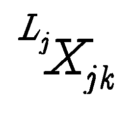 를 나타낸 것이다.
또한, 도 15a 상단에는 이미지 취득 지점  에 이미지 평면이 매핑되어 있는데,
  로 표시된 좌표축의 원점은 이미지 센서(카메라)의 중심점을 나타내고 이미지 평면은 이미지 센서에 탑재된 CMOS 센서에서 3차원 공간을 바라보았을때 형성되는 2차원 이미지 평면을 나타낸다.
이때, 이미지 취득 지점  로부터 깊이값까지의 거리는 제2깊이값거리
  이고, 이미지 취득 지점
  로부터 깊이값까지 일직선으로 연결한 선과 이미지 평면이 교차되는 지점에 이미지 픽셀 p가 표시되어 있는데, 그 픽셀 p와 제2깊이값거리
  가 서로 매핑이 된다는 것을 의미한다.
다만, 어떤 깊이값의 경우에는 이미지 취득 지점  로부터 깊이값까지 일직선으로 연결한 선이 이미지 평면을 벗어나 교차 지점이 존재하지 않을 수 있는데, 이 경우에는 대응되는 깊이값이 존재하지 않는 이미지 픽셀인 미매핑 픽셀이 발생하게 된다.
도 15b는 본 발명의 다른 실시예에 따른 깊이-이미지 연계를 설명하기 위하여 도시한 도면이다.
도 15b에서, 추정된 i번째 이미지 취득 지점  와 추정된 j-1, j, j+1번째 깊이값 취득 지점
  ,
,  ,
,  가 W로 표시된 좌표축과 화살표로 연결되어 있는데, 이는 이미지 취득 지점
  에서의 이미지취득포즈와 깊이값 취득 지점
  ,
,  ,
,  에서의 깊이취득포즈들은 기준 좌표계를 기준으로 추정된다는 것을 의미한다.
또한, 도 15b 하단에 산재되어 분포되어 있는 점들은 깊이취득포즈들 각각에서 취득된 취득 깊이값들을 나타내는데, W로 표시된 좌표축이 점과 화살표로 연결되어 있는 것은 깊이값이 기준 좌표계 기준으로 표시된다는 것을 의미한다. 다만, 다른 실시예에서는 취득 깊이값이 이미지 취득 지점  를 원점으로 하는 취득 좌표계를 기준으로 표시될 수도 있다.
또한, 도 15b 상단에는 이미지 취득 지점  에 대표 이미지가 매핑되어 있는데, 이는 대표 이미지가 이미지 취득 지점
  를 원점으로 하는 취득좌표계를 대표하는 이미지로 설정되어 있음을 나타낸다.
즉, 도 15b의 깊이-이미지 연계에 따르면, 이미지취득포즈와 깊이취득포즈는 기준 좌표계를 기준으로 추정되고, 이미지취득포즈에는 그 이미지취득포즈에서 취득된 복수의 취득 이미지 중에서 한개의 대표 이미지가 그 이미지취득포즈를 원점으로 취득좌표계를 대표하는 이미지로서 선정되어 연동되고, 취득 깊이값은 기준 좌표계를 기준으로 추정된다.
한편, 도 15b의 실시예에서의 이미지 센서의 화각이 거리 센서의 화각보다 크고, 깊이값 취득 지점  ,
,  ,
,  에서의 깊이취득포즈들에서 취득된 깊이지도가 모두 이미지 취득 지점
  의 취득 좌표계에 연동된 대표 이미지의 화각 내에 포함된다면, 투영 이미지 생성 장치는 이미지 취득 지점
  의 취득 좌표계에 연동된 하나의 대표 이미지와 깊이값 취득 지점
  ,
,  ,
,  에서의 깊이취득포즈들에서 취득된 복수의 깊이지도를 이용하여 투영 이미지를 생성할 수 있다.
도 15c는 본 발명의 또 다른 실시예에 따른 깊이-이미지 연계를 설명하기 위하여 도시한 도면이다.
도 15c에서, 추정된 i번째 이미지 취득 지점  가 W로 표시된 좌표축과 화살표로 연결되어 있는데, 이는 이미지 취득 지점
  에서의 이미지취득포즈가 기준 좌표계를 기준으로 추정된다는 것을 의미한다.
또한, 추정된 j-1, j, j+1번째 깊이값 취득 지점  ,
,  ,
,  가 이미지 취득 지점
  로 표시된 좌표축과 화살표로 연결되어 있는데, 이는 추정된 j-1, j, j+1번째 깊이값 취득 지점
  ,
,  ,
, 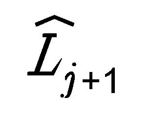 의 깊이취득포즈가 이미지 취득 지점
  를 원점으로 하는 취득 좌표계 기준으로 추정된다는 것을 의미한다.
또한, 도 15c에서 이미지 취득 지점  로 표시된 좌표축이 하단의 깊이값을 나타내는 복수의 점들 중 하나와 화살표로 연결되어 있는 것은 취득 깊이값이 이미지 취득 지점
  를 원점으로 하는 취득 좌표계를 기준으로 표시된다는 것을 나타낸다. 다만, 다른 실시예에서는 취득 깊이값이 기준 좌표계를 기준으로 표시될 수도 있다.
또한, 도 15c 상단에는 이미지 취득 지점  에 대표 이미지가 매핑되어 있는데, 이는 대표 이미지가 이미지 취득 지점
  를 원점으로 하는 취득좌표계를 대표하는 이미지로 설정되어 있음을 나타낸다.
즉, 도 15c의 깊이-이미지 연계에 따르면, 이미지취득포즈는 기준 좌표계를 기준으로 추정되고, 깊이취득포즈는 이미지취득포즈를 원점으로 하는 취득좌표계를기준으로 추정되고, 이미지취득포즈에는 그 이미지취득포즈에서 취득된 복수의 취득 이미지 중에서 한개의 대표 이미지가 그 이미지취득포즈를 원점으로 하는 취득좌표계를 대표하는 이미지로서 선정되어 연동되고, 취득 깊이값은 이미지취득포즈를 원점으로 하는 취득좌표계를 기준으로 추정된다.
도 15c에 따른 투영 이미지 생성 방법은 도 16을 참조하여 설명한다.
도 16은 본 발명의 다른 실시예에 따른 투영 이미지 생성 방법을 설명하기 위하여 도시한 흐름도이다.
단계 1610에서는, 투영 이미지 생성 장치가 실제 3차원 공간에 대하여 취득된 복수의 취득 이미지에 대응되는 복수의 이미지취득포즈를 기준 좌표계를 기준으로 추정하고, 복수의 취득 깊이값에 대응되는 복수의 깊이취득포즈를 복수의 이미지취득포즈 각각을 원점으로 하는 취득 좌표계 기준으로 추정한다.
단계 1620에서는, 투영 이미지 생성 장치가 실제 3차원 공간에 대응되는 가상의 3차원 공간에서의 사용자의 위치 및 각도를 포함하는 사용자포즈를 기준 좌표계를 기준으로 취득한다.
단계 1630에서는, 투영 이미지 생성 장치가 사용자 포즈에 대응되는 대응이미지취득포즈 및 적어도 하나의 대응깊이취득포즈에 기초하여, 복수의 취득 깊이값을 복수의 취득 이미지 중 적어도 하나에 투영한 투영 이미지를 생성한다.
이때, 투영 이미지 생성 장치는 복수의 취득 깊이값 중에서 투영 이미지 생성에 이용될 복수의 취득 이미지 각각이 취득된 시점으로부터 소정 시간 이내에 취득된 취득 깊이값만을 이용하여 대표 이미지에 투영함으로써 투영 이미지를 생성할 수도 있다. 이는, 고리 닫힘 상황 등의 발생으로 인한 투영 이미지의 왜곡을 최소화하기 위한 것이다.
또한, 투영 이미지 생성 장치는 대응깊이취득포즈에 연동된 대표 이미지를 이용하여 투영 이미지를 생성하게 되는데, 대응깊이취득포즈에 연동할 대표 이미지를 선정할때 깊이-이미지연계정보를 이용할 수도 있다.
예컨대, 투영 이미지 생성 장치는 깊이-이미지연계정보를 통해 취득 이미지와 사용자 시야와의 중첩 영역을 검출한 후, 그 중첩 영역이 가장 넓은 취득 이미지를 대표 이미지로 설정할 수 있다. 이와 같은 실시예는, 사용자포즈와 가장 가까운 이미지취득포즈에 연계된 이미지를 대표이미지로 선정하는 방법 등으로도 용이하게 구현될 수 있다.
도 17은 본 발명의 일 실시예에 따라 유실시야영역이 존재하는 경우의 투영 이미지 생성 방법을 설명하기 위하여 도시한 흐름도이고, 도 18은 이미지 센서의 화각이 사용자 시야를 포함하는 환경을 설명하기 위하여 도시한 도면이고, 도 19는 이미지 센서의 화각이 사용자 시야를 포함하지 못하는 환경을 설명하기 위하여 도시한 도면이다.
도 17의 실시예는 도 1의 단계 130 또는 도 16의 단계 1630을 한정하는 실시예로서, 도 1의 실시예의 단계 110 및 단계 120 이후에 수행되고, 도 16의 단계 1610 및 단계 1620 이후에 수행되는 단계이다.
단계 1710에서는, 투영 이미지 생성 장치가 사용자의 시야각에 대응되는 가상의 3차원 공간상의 영역 중에서 대표 이미지에 포함되지 않은 유실시야영역이 존재하는지 여부를 판단한다.
도 18을 참조하면, i번째 이미지 취득 지점 Ci에서의 이미지 센서의 화각이 사용자의 위치 지점 u에서의 사용자의 시야를 모두 포함하므로, 유실 시야 영역은 존재하지 않는다.
하지만, 도 19를 참조하면, i번째 이미지 취득 지점 Ci와 사용자의 위치 지점 u의 하단에 회색 정사각형 형태의 장애물이 존재하여, i번째 이미지 취득 지점 Ci에 위치한 이미지 센서의 화각을 제한시킴으로써, 이미지 센서의 시야 한계가 사용자의 시야한계보다 좁아지면서 x표로 표시된 유실 시야 영역이 발생하게 된다. 가상의 3차원 공간상에서 사용자가 유실 시야 영역을 바라보게 되면, 대표 이미지에는 그 유실 시야 영역에 해당하는 픽셀이 존재하지 않으므로 까만색 또는 흰색으로 표시될 수 있다.
한편, 종래의 취득 좌표계 기준 투영 이미지 생성 방법에 따르면 어느 취득 이미지가 사용자 시야에 포함되는지 알 수 없어, 유실 시야 영역에 대응되는 픽셀이 까만색 또는 흰색을 가지도록 표시된 투영 이미지를 생성하였다.
하지만, 본 발명의 일 실시예에 따르면 깊이-이미지 연계 정보를 통해 깊이값을 매개로 취득 이미지의 어떤 픽셀이 사용자 시야안에 포함되는지 확인할 수 있고, 이를 통해 어떤 취득 이미지가 사용자 시야 안에 들어와야 하는지 확인할 수 있게 되어, 유실 시야 영역에 대응되는 픽셀이 실제 3차원 공간에서와 동일한 색깔을 가지도록 표시된 투영 이미지를 생성할 수 있게 된다. 즉, 본 발명의 일 실시예에 따르면, 도 19와 같이 장애물이 존재하거나, 이미지취득포즈와 사용자 포즈가 상이한 경우에도 해당 위치에서의 사용자의 임의의 시야에 대응되는 자연스러운 투영 이미지를 생성할 수 있게 되는 효과가 있다.
단계 1720에서는, 유실시야영역이 존재한다고 판단되면, 투영 이미지 생성 장치가 복수의 취득 이미지에 포함된 복수의 픽셀들에 대응되는 복수의 취득 깊이값이 매칭된 정보인 깊이-이미지연계정보에 기초하여 복수의 취득 이미지 중에서 보강 이미지를 선정한다.
이때, 보강 이미지를 선정하는 동작에 대한 구체적인 설명은 도 20을 참조하여 후술한다.
단계 1730에서는, 투영 이미지 생성 장치가 보강 이미지와 대표 이미지를 상호 조합함으로써 조합 이미지를 생성한다.
이때, 투영 이미지 생성 장치는 보강 이미지를 대표 이미지와 동일한 가중치로 상호 조합하거나, 보강 이미지를 대표이미지보다 낮은 가중치로 상호 조합하여 조합 이미지를 생성할 수 있다.
단계 1742에서는, 투영 이미지 생성 장치가 복수의 취득 깊이값을 조합 이미지에 투영한 투영 이미지를 생성한다.
단계 1744에서는, 1742 단계에서 유실시야영역이 존재하지 않는다고 판단되면, 투영 이미지 생성 장치가 복수의 취득 깊이값을 대표 이미지에 투영한 투영 이미지를 생성한다.
도 20은 본 발명의 일 실시예에 따른 보강 이미지 선정 방법을 설명하기 위하여 도시한 흐름도이다.
단계 2010에서는, 투영 이미지 생성 장치가 사용자포즈를 중심으로 사용자의 시야각 내에 포함되는 깊이값인 복수의 사용자시야깊이값을 검출한다.
전술한 바와 같이, 투영 이미지 생성 장치는 사용자포즈를 중심으로 레이캐스팅 등을 수행하여 복수의 사용자시야깊이값을 검출할 수도 있다.
단계 2020에서는, 투영 이미지 생성 장치가 복수의 사용자시야깊이값 중에서 유실 시야 영역에 해당하는 깊이값인 복수의 유실시야깊이값을 검출한다.
예컨대, 사용자가 특정한 사용자 포즈에서 한바퀴 돌면서 3차원 공간을 바라보는 경우 360도에 해당하는 복수의 사용자시야깊이값이 존재하지만, 그 중에서도 특정한 각도에 유실 시야 영역이 존재하게 되고, 투영 이미지 생성 장치는 그 유실 시야 영역에 해당하는 깊이값을 유실시야깊이값으로서 검출하게 된다.
단계 2030에서는, 투영 이미지 생성 장치가 깊이-이미지연계정보에 기초하여, 복수의 유실시야깊이값에 대응되는 복수의 유실픽셀을 검출한다.
예컨대, 투영 이미지 생성 장치는 깊이-이미지연계정보를 이용하면 복수의 유실시야깊이값 각각에 대응되는 픽셀이 무엇인지를 알 수 있고, 그와 같이 복수의 유실시야깊이값 각각에 대응되는 픽셀을 유실픽셀로서 검출하게 된다.
단계 2040에서는, 투영 이미지 생성 장치가 그 검출된 복수의 유실픽셀에 기초하여, 복수의 취득 이미지 중에서 복수의 유실픽셀을 포함하는 취득 이미지인 보강 이미지를 선정한다.
도 21은 사용자 이동에 따른 본 발명과 종래 기술의 차이점을 설명하기 위하여 도시한 도면이다.
도 21에는 이미지 취득 경로가 A-B-C-D...-X-Y-Z와 같이 도시되어 있는데, W전술한 바와 같이 종래에는 사용자가 이와 같은 이미지가 취득된 경로를 그대로 따라 가는 경우에 한해서만 투영 이미지를 제공해줄 수 있었으나, 본 발명에서는 사용자가 이미지 취득 경로를 벗어나 C에서 X로 이동하는 경우에도 자연스러운 투영 이미지를 제공해줄 수 있는 장점이 있다.
도 22는 본 발명의 일 실시예에 따른 파라미터 기반의 깊이값 메쉬 구조를 설명하기 위하여 도시한 도면이다.
도 22는 깊이 지도가 미리 설정된 파라미터를 기반으로 하는 메쉬 구조의 취득 깊이값으로 구성되는 경우를 도시한 것으로, 좌측의 메쉬는 천정이 기울어진 박스로 정의된 파라미터화된 패턴으로 근사화된 메쉬 구조이고, 가운데는 모든 깊이값을 내포하는 바운딩박스로 근사화된 메쉬 구조이고, 우측은 메쉬수를 줄이면서도 많은 수의 깊이값을 포함하도록 근사화된 기하형태의 메쉬 구조를 나타낸다. 이와 같은 형태의 메쉬 구조의 깊이값을 이용하게 되면 모든 이미지 픽셀에 대해 깊이-이미지 연계가 수행되지 않은 경우에도 메쉬 단위로 투영 이미지를 생성할 수 있게되는 장점이 있다.
도 23은 본 발명의 일 실시예에 따른 투영 이미지 생성 장치를 설명하기 위하여 도시한 도면이다.
도 23을 참조하면, 본 발명의 일 실시예에 따른 투영 이미지 생성 장치는 데이터 포즈추정부(2310), 사용자 포즈 취득부(2320) 및 이미지 생성부(2330)를 포함한다.
데이터 포즈 추정부(2310)는 실제 3차원 공간에 대하여 취득된 복수의 취득 이미지 및 복수의 취득 깊이값 각각의 취득 위치 및 취득 각도를 포함하는 복수의 이미지취득포즈 및 복수의 깊이취득포즈를 기준 좌표계를 기준으로 추정한다.
다른 실시예에서, 데이터 포즈 추정부(2310)는 이미지취득포즈는 기준 좌표계를 기준으로 추정하고, 깊이취득포즈는 이미지취득포즈 각각을 원점으로 하는 취득 좌표계 기준으로 추정할 수도 있다.
바람직하게는, 본 발명의 일 실시예에 따른 투영 이미지 생성 장치는 복수의 취득 이미지, 복수의 취득 이미지가 취득된 취득 시간 정보, 복수의 취득 깊이값, 복수의 취득 깊이값이 취득된 취득 시간 정보, 복수의 취득 이미지에 대응되는 복수의 이미지 취득 포즈, 상기 복수의 취득 깊이값에 대응되는 깊이취득 포즈, 관성 변화 정보, 표식관측 정보, 광파계 정보 등의 환경 센싱 정보를 복수의 센서들로부터 수신하여 저장하는 저장부(미도시)를 더 포함할 수 있다.
이때, 환경 센싱 정보를 센싱하는 센서는 도 3에서와 같이 이미지 센서와 거리 센서가 통합된 통합 센서일 수도 있고, 그 밖에 다른 센서까지 모두 통합된 형태의 통합 센서일 수도 있다. 도 3의 통합 센서에서는 이미지 센서와 거리 센서가 강성체결되어 있는데, 이와 같은 경우에는 두 센서간의 상대적 포즈는 상수값으로 사전에 주어질 수 있다. 또한, 환경 센싱 정보는 로봇에 탑재된 통합 센서 또는 사람의 어깨 등에 착용된 통합 센서가 실내 혹은 실외 환경을 이동하면서 정지된 상태 또는 이동하는 상태에서 취득한 정보일 수 있다.
데이터 포즈 추정부(2310)는 저장부에 저장된 환경 센싱 정보를 읽어와 기준 좌표계를 기준으로 모든 이미지취득포즈 및 깊이취득포즈를 추정하게 된다. 다만, 다른 실시예에서는 데이터 포즈 추정부(2310)가 깊이취득포즈를 취득 좌표계를 기준으로 추정한 후, 깊이취득포즈와 이미지취득포즈간의 상대 포즈를 이용하여 기준 좌표계 기준으로 깊이취득포즈를 추정할 수도 있다.
또한, 데이터 포즈 추정부(2310)는 이미지취득포즈에서 취득된 복수의 취득 이미지 중에서 그 이미지취득포즈를 원점으로 하는 취득 좌표계를 대표하는 대표 이미지를 설정하여 그 취득 좌표계에 연동시킨 후 저장부에 저장할 수도 있다. 이에 따라, 사용자가 가상의 3차원 공간에서 특정한 이미지취득포즈의 취득 좌표계 내에 진입하게 되면, 해당 취득 좌표계에서 소정 임계치 이내의 거리 내에서는 사용자가 이동하더라도 사용자에게는 그 취득 좌표계를 대표하는 대표 이미지만이 표시되게 된다.
사용자 포즈 취득부(2320)는 실제 3차원 공간에 대응되는 가상의 3차원 공간에서의 사용자의 위치 및 각도를 포함하는 사용자포즈를 기준 좌표계를 기준으로 취득한다.
바람직하게는, 본 발명의 일 실시예에 따른 투영 이미지 생성 장치는 가상의 3차원 공간에서 사용자를 이동시키고, 사용자의 시야각 등을 설정할 수 있는 사용자 입력부(미도시)를 더 포함할 수 있다.
사용자 입력부는 키보드, 조이스틱 형태일 수도 있고, HMD(Head Mount Display)에 구비된 각속도 센서, 가속도 센서, 지자기 센서 등에 기초한 입력 수단일 수 있고, 카메라 영상의 옵티컬플로우(optical flow)를 통한 입력 수단일 수도 있다.
이미지 생성부(2330)는 사용자 포즈에 대응되는 대응이미지취득포즈 및 적어도 하나의 대응깊이취득포즈에 기초하여, 복수의 취득 깊이값을 복수의 취득 이미지 중 적어도 하나에 투영한 투영 이미지를 생성한다.
보다 구체적으로는, 이미지 생성부(2330)는 하나의 대표 이미지(또는 조합 이미지)에 복수의 대응깊이취득포즈에서 취득된 복수의 깊이값을 투영함으로써 투영 이미지를 생성하게 된다.
이미지 생성부(2330)의 구체적인 구성에 대해서는 도 24를 참조하여 후술한다.
바람직하게는, 본 발명의 일 실시예에 따른 투영 이미지 생성 장치는 복수의 취득 이미지 중에서 취득 이미지의 거리별, 이동시간별, 형상특징별 기준에 따라 이미지를 샘플링하여, 투영 이미지 생성에 이용되는 취득 이미지 개수를 줄여주는 이미지 관리부(미도시)를 더 포함할 수 있다. 즉, 이미지 관리부는 저장부에 저장된 취득 이미지들 중에서 취득 이미지에 동적인 부분이 있거나, 사람얼굴 등 개인정보에 해당하는 부분들이 존재하는 취득 이미지에 대해서는 후가공을 수행할 수 있다. 또한, 이미지 관리부는 고리 닫힘 상황이 발생한 지점에서 복수의 취득 이미지들이 다른 촬영조건(조명, 노출시간, 렌즈초점거리등)에서 취득되어 있다면 그와 같은 취득 이미지에 대해서는 그 차이를 최소화하는 보정을 수행할 수도 있다.
한편, 이미지 관리부는 이와 같은 처리를 마친 취득 이미지를 다시 저장부에 저장함으로써, 투영 이미지 생성시에 이용되는 취득 이미지 개수 및 취득 이미지간의 차이를 줄여줄 수 있다. 또한, 취득 이미지간 촬영 조건의 차이가 소정 임계값 이상인 경우에는 경보를 발생시킨 후, 해당 이미지의 차이를 줄이는 보정을 하거나 해당 이미지를 삭제할 수 있다.
바람직하게는, 본 발명의 일 실시예에 따른 투영 이미지 생성 장치는 거리 센서를 통해 취득된 취득 깊이값에 포함된 노이즈를 제거하는 동작을 수행하는 깊이값 관리부(미도시)를 더 포함할 수 있다. 이때, 취득 깊이값에 포함된 노이즈를 제거하는 동작은 2015.05.06에 출원된 한국특허출원 10-2015-0062890 " 외곽 공간 특징 정보 추출 방법 "을 참조하여 수행될 수 있다.
취득 이미지와는 달리 취득 깊이값에는 유리나 거울 또는 반사재질 물체에 대해 많은 노이즈들이 포함될 수 있다. 또한, 거리 센서의 넓은 탐침거리로 인해 한 물체가 여러번 관찰되기도 하고, 특정 영역에 많은 개수의 깊이값이 맺히기도 한다. 이러한 노이즈나 불균형적인 깊이값 분포등이 향후 투영이미지의 실감성을 현격히 저해할 수 있기 때문에, 깊이값 관리부는 저장부에 저장된 취득 깊이값에 포함된 노이즈를 사전에 제거하는 동작을 수행할 수 있다.
다른 실시예에서는, 이미지 생성부(2330)는 이미지 관리부 및 깊이값 관리부를 거친 취득 이미지 및 취득 깊이값을 이용하여 투영 이미지를 생성할 수 있다.
도 24는 본 발명의 일 실시예에 따른 이미지 생성부를 설명하기 위하여 도시한 도면이다.
도 24를 참조하면, 본 발명의 일 실시예에 따른 이미지 생성부(2330)는 사용자 시야 판단부(2332), 보강 이미지 선정부(2334), 조합 이미지 생성부(2336) 및 투영 이미지 생성부(2338)를 포함한다. 다만, 다른 실시예에서는 보강 이미지 선정부(2334) 및 조합 이미지 생성부(2336)는 생략될 수 있다.
사용자 시야 판단부(2332)는 사용자포즈에서의 사용자의 시야각에 대응되는 가상의 3차원 공간상의 영역 중에서 대표 이미지에 포함되지 않은 유실시야영역이 존재하는지 여부를 판단한다.
다른 실시예에서, 사용자 시야 판단부(2332)는 사용자 포즈가 이미지취득포즈, 깊이취득포즈와 동일한지 상이한지를 판단할 수도 있다.
또 다른 실시예에서는, 이미지취득포즈에서 취득된 취득 이미지의 화각 내에 사용자 포즈에서의 사용자의 시야가 소정 임계치 이상 포함되는 경우 사용자 포즈와 이미지 취득 포즈가 동일하고, 그 외의 경우에는 사용자 포즈와 이미지 취득 포즈가 상이하다고 판단할 수도 있다. 예컨대, 이미지취득포즈에서 취득된 취득 이미지의 화각과 사용자 포즈에서의 사용자의 시야가 90% 이상 중첩되는 경우에는 사용자 포즈와 이미지 취득 포즈가 동일하다고 판단할 수 있다.
보강 이미지 선정부(2334)는 유실시야영역이 존재한다고 판단되면, 복수의 취득 이미지에 포함된 복수의 픽셀들에 대응되는 복수의 취득 깊이값이 매칭된 정보인 깊이-이미지연계정보에 기초하여 복수의 취득 이미지 중에서 보강 이미지를 선정한다.
조합 이미지 생성부(2336)는 보강 이미지를 대표 이미지와 상호 조합함으로써 조합 이미지를 생성할 수 있다.
이때, 조합 이미지 생성부(2336)는 보강 이미지를 대표 이미지와 동일한 가중치로 상호 조합하거나, 보강 이미지를 대표이미지보다 낮은 가중치로 상호 조합하여 조합 이미지를 생성할 수 있다.
예컨대, 조합 이미지 생성부(2336)는 투명도를 매우 높인 보강 이미지를 레이어 형태로 대표 이미지와 조합함으로써, 보강 이미지의 가중치가 낮은 조합 이미지를 생성할 수도 있다.
투영 이미지 생성부(2338)는 복수의 취득 깊이값을 조합 이미지에 투영한 투영 이미지를 생성한다.
이와 같이, 투영 이미지 생성부(2338)는 조합 이미지를 이용하여 투영 이미지를 생성할 수도 있고, 대표 이미지만을 이용하여 투영 이미지를 생성할 수 있는데, 사용자 포즈와 그 사용자 포즈에 대응되는 대응이미지취득포즈가 동일한지 상이한지에 따라 다음과 같이 동작을 수행하게 된다.
첫 번째로, 사용자 포즈와 대응이미지취득포즈가 동일하고, 그 대응이미지취득포즈에서 취득된 취득 이미지의 화각과 대응깊이취득포즈에서 취득된 복수의 취득 깊이값으로 구성되는 깊이 지도의 화각이 동일한 경우(포즈 동일-화각 동일)에는 투영 이미지 생성부(2338)는 그 취득된 취득 이미지와 취득 깊이값을 이용하여 투영 이미지를 생성한다. 이때, 투영 이미지 생성부(2338)는 대응이미지취득포즈에서 취득된 복수의 취득 이미지 중에서 하나의 대표 이미지를 선정하고, 그 선정된 대표 이미지에 취득 깊이값을 투영하여 투영 이미지를 생성하게 된다.
두 번째로, 사용자 포즈와 대응이미지취득포즈가 동일하지만, 그 대응이미지취득포즈에서 취득된 취득 이미지의 화각이 대응깊이취득포즈에서 취득된 깊이 지도의 화각보다 큰 경우(포즈 동일-화각 상이)에는, 투영 이미지 생성부(2338)는 하나의 대응이미지취득포즈의 취득 좌표계에 연동된 하나의 대표이미지에 복수의 대응깊이취득포즈에서 취득된 복수의 깊이 지도를 투영하여 투영 이미지를 생성한다.
세 번째로, 사용자 포즈와 대응이미지취득포즈가 상이하면, 투영 이미지 생성부(2338)는 하나의 대응이미지취득포즈의 취득 좌표계에 연동된 하나의 대표이미지에 보강 이미지를 조합한 조합 이미지와 복수의 대응깊이취득포즈에서 취득된 복수의 깊이 지도를 이용하여 투영 이미지를 생성한다.
전술한 바와 같이, 조합 이미지 생성시의 대표 이미지의 가중치와 보강 이미지의 가중치가 동일할 경우에는 실제 3차원 공간상의 한점이 다수의 취득 이미지를 이용하여 표현됨으로써 불가피하게 발생하는 최소 수픽셀 이상의 위치추정오차로 인해 투영 이미지의 실감성이 현저히 저하될 수 있으므로, 조합 이미지 생성시의 대표 이미지의 가중치는 보강 이미지의 가중치보다 높게 설정되어야 한다. 다만, 대표 이미지의 가중치가 99.9이고 보강 이미지의 가중치 0.1인 경우과 같이 보강 이미지의 가중치가 매우 작은 경우에는 해당 보강 이미지가 투영 이미지의 실감성에 미치는 영향이 미미하므로, 해당 보강 이미지는 조합 이미지 생성시에 이용되지 않을 수 있다.
한편, 이미지취득포즈의 취득 좌표계에 연동되는 대표 이미지는 깊이-이미지연계정보를 통해 취득 이미지와 사용자 시야와의 중첩 영역을 검출한 후 그 중첩 영역이 가장 넓은 취득 이미지를 대표 이미지로 설정하는 방식, 이미지취득포즈로부터 가장 가까운 거리의 취득 이미지를 대표 이미지로 설정하는 방식 등에 의해 설정될 수 있다. 이때, 이미지취득포즈부터 취득 이미지까지의 거리는 유클리디언 메트릭을 기반으로 계산되는 값이며, 예컨대 절대 차이값, 벡터의 2차놈 (2-norm)등이 이용될 수 있다.
본 발명은 실내환경의 방, 집, 쇼핑몰, 호텔, 터미널, 공항 등에 사용될수 있고, 실외환경의 문화유산, 도시-지형정보의 보존 등에 사용될 수 있으며, 실내외 환경의 아파트 단지, 학교 캠퍼스 등에 사용될 수 있는데, 이와 같은 장소들에 본 발명을 적용함으로써 3차원 가상지도를 만들 수 있다.
이와 같은 3차원 지도정보는 다양한 서비스를 창출할 수 있는 플랫폼 역할을 하므로 이를 활용하여 부동산연계서비스, 시설홍보 서비스, 게임컨텐츠 제작서비스, 유적지-관광지 실감체험 서비스, 지도내 물품정보를 연계한 O2O서비스등을 실시할 수 있다.
또한, 사전 제작된 3차원 지도정보에서 핵심 특징점들을 추출하여 데이터베이스에 보관하고 있고, 사용자가 해당 실제공간에서 카메라 혹은 관성센서정보를 활용하여 데이터를 취득한 경우, 데이터베이스의 특징점과 사용자가 제공한 특징점을 비교하여 사용자 위치를 즉시 찾을 수 있으며, 이를 통해 사용자 디바이스의 디스플레이 장치를 사용자 시야로 하여 투영이미지를 생성시킬 수 있고, 사용자의 디바이스 조작에 대응하여 연속된 투영이미지를 제공하여, 사용자가 디스플레이를 통해 3차원 지도를 경험토록 할 수 있다.
예컨대, 사용자는 상점에 들어가 보지 않고도 상점의 분위기나 특정 물건에 대한 세부정보도 확인하도록 할 수 있다. 또한, 본 발명은 재난안전관리를 위해서도 사용가능한데, 원자력 발전소와 같이 사람이 긴급히 출입하여야 하는 위험지역의 경우, 사전에 로봇등을 통하여 데이터를 간단히 취득하고 본 발명에 따라 가상공간으로 구축한 이후, 침투 요원에게 HMD등을 통해 공간을 충분히 경험하게 함으로써 재난 시 긴급대처가 가능하도록 할 수 있다.
이제까지 본 발명에 대하여 그 바람직한 실시예들을 중심으로 살펴보았다. 본 발명이 속하는 기술 분야에서 통상의 지식을 가진 자는 본 발명이 본 발명의 본질적인 특성에서 벗어나지 않는 범위에서 변형된 형태로 구현될 수 있음을 이해할 수 있을 것이다. 그러므로 개시된 실시예들은 한정적인 관점이 아니라 설명적인 관점에서 고려되어야 한다. 본 발명의 범위는 전술한 설명이 아니라 특허청구범위에 나타나 있으며, 그와 동등한 범위 내에 있는 모든 차이점은 본 발명에 포함된 것으로 해석되어야 할 것이다.
Claims (24)
- 실제 3차원 공간에 대하여 취득된 복수의 취득 이미지 및 복수의 취득 깊이값 각각의 취득 위치 및 취득 각도를 포함하는 복수의 이미지취득포즈 및 복수의 깊이취득포즈를 기준 좌표계를 기준으로 추정하는 단계;상기 실제 3차원 공간에 대응되는 가상의 3차원 공간에서의 사용자의 위치 및 각도를 포함하는 사용자포즈를 기준 좌표계를 기준으로 취득하는 단계; 및상기 사용자 포즈에 대응되는 대응이미지취득포즈 및 적어도 하나의 대응깊이취득포즈에 기초하여, 상기 복수의 취득 깊이값을 상기 복수의 취득 이미지 중 적어도 하나에 투영한 투영 이미지를 생성하는 단계를 포함하는 것을 특징으로 하는 투영 이미지 생성 방법.
- 제1항에 있어서,상기 투영 이미지 생성에 이용되는 상기 복수의 취득 이미지 중 적어도 하나는상기 대응이미지취득포즈에서 취득된 취득 이미지로서 상기 대응이미지취득포즈를 원점으로 하는 좌표계인 취득좌표계를 대표하는 이미지로 설정된 대표 이미지이고,상기 투영 이미지 생성에 이용되는 상기 복수의 취득 깊이값은상기 대응깊이취득포즈에서 취득된 복수의 깊이값으로서 상기 기준 좌표계의 원점을 기준으로 하는 복수의 깊이값 또는 상기 취득좌표계의 원점을 기준으로 하는 복수의 깊이값 중에서 상기 대표 이미지의 화각에 포함되는 깊이값인 복수의 대응깊이값을 포함하는 것을 특징으로 하는 투영 이미지 생성 방법.
- 제2항에 있어서,상기 투영 이미지를 생성하는 단계는상기 복수의 대응깊이값 각각에 대응되는 상기 대표 이미지에 포함된 픽셀인 복수의 대응픽셀에 상기 복수의 대응깊이값을 투영하여 생성하는 것을 특징으로 하는 투영 이미지 생성 방법.
- 제2항에 있어서,상기 사용자포즈가 상기 대응이미지취득포즈와 상이하고, 상기 사용자포즈에서의 상기 사용자의 시야각에 대응되는 상기 가상의 3차원 공간상의 영역 중에서 상기 대표 이미지에 포함되지 않은 유실시야영역이 존재하는 경우,상기 투영 이미지를 생성하는 단계는상기 대표 이미지를 제외한 상기 복수의 취득 이미지 중에서 상기 유실시야영역에 해당하는 픽셀인 복수의 유실픽셀을 포함하는 취득 이미지인 보강 이미지 및 상기 대표 이미지를 이용하여 상기 투영 이미지를 생성하는 단계를 포함하는 것을 특징으로 하는 투영 이미지 생성 방법.
- 제4항에 있어서,상기 보강 이미지 및 상기 대표 이미지를 이용하여 상기 투영 이미지를 생성하는 단계는상기 유실시야영역이 존재하는지 여부를 판단하는 단계;상기 유실시야영역이 존재한다고 판단되면, 상기 복수의 취득 이미지에 포함된 복수의 픽셀들에 대응되는 상기 복수의 취득 깊이값이 매칭된 정보인 깊이-이미지연계정보에 기초하여 상기 복수의 취득 이미지 중에서 상기 보강 이미지를 선정하는 단계;상기 보강 이미지를 상기 대표 이미지보다 낮은 가중치로 상호 조합함으로써 조합 이미지를 생성하는 단계; 및상기 복수의 취득 깊이값을 상기 조합 이미지에 투영한 투영 이미지를 생성하는 단계를 포함하는 것을 특징으로 하는 투영 이미지 생성 방법.
- 제5항에 있어서,상기 복수의 취득 이미지 중에서 상기 보강 이미지를 선정하는 단계는상기 사용자포즈를 중심으로 레이캐스팅(raycasting)을 수행하여 상기 사용자의 시야각 내에 포함되는 깊이값인 복수의 사용자시야깊이값을 검출하는 단계;상기 복수의 사용자시야깊이값 중에서 상기 유실 시야 영역에 해당하는 깊이값인 복수의 유실시야깊이값을 검출하는 단계;상기 깊이-이미지연계정보에 기초하여, 상기 복수의 유실시야깊이값에 대응되는 상기 복수의 유실픽셀을 검출하는 단계; 및상기 검출된 복수의 유실픽셀에 기초하여, 상기 복수의 취득 이미지 중에서 상기 보강 이미지를 선정하는 단계를 포함하는 것을 특징으로 하는 투영 이미지 생성 방법.
- 제5항에 있어서,상기 깊이-이미지연계정보는상기 깊이취득포즈에서 취득된 복수의 취득 깊이값으로부터 상기 깊이취득포즈까지의 거리인 복수의 제1깊이값거리를 산출하는 단계;상기 이미지취득포즈 및 상기 깊이취득포즈를 이용하여, 상기 제1깊이값거리를 상기 깊이취득포즈에서 취득된 상기 각각의 복수의 취득 깊이값으로부터 상기 이미지취득포즈까지의 거리인 복수의 제2깊이값거리로 변환하는 단계; 및상기 취득 이미지 취득에 이용된 이미지 센서에 대응되는 카메라 행렬 및 상기 복수의 제2깊이값거리를 이용하여, 상기 취득 이미지에 포함된 복수의 픽셀에 상기 복수의 취득 깊이값을 매핑하는 단계를 통해 산출되는 것을 특징으로 하는 투영 이미지 생성 방법.
- 제7항에 있어서,상기 깊이취득포즈에서 취득된 복수의 취득 깊이값으로부터 상기 깊이취득포즈까지의 거리인 복수의 제1깊이값거리를 산출하는 단계는상기 복수의 취득 깊이값 각각의 취득 시간이 소정 시간 간격 이내인 상기 복수의 취득 깊이값만을 이용하여 수행되는 것을 특징으로 하는 투영 이미지 생성 방법.
- 제2항에 있어서,상기 사용자포즈가 상기 대응이미지취득포즈와 동일하고, 상기 대응이미지취득포즈에서 취득된 상기 취득 이미지의 화각이 상기 대응깊이취득포즈에서 취득된 상기 복수의 취득 깊이값으로 구성되는 깊이 지도의 화각보다 큰 경우,상기 투영 이미지를 생성하는 단계는상기 대표 이미지가 취득된 상기 대응이미지취득포즈로부터 소정 거리 이내에 속하는 복수의 상기 대응깊이취득포즈로부터 취득된 복수의 상기 깊이 지도와 상기 대표 이미지를 이용하여 수행되는 것을 특징으로 하는 투영 이미지 생성 방법.
- 제9항에 있어서,상기 사용자포즈가 상기 대응이미지취득포즈와 동일하고, 상기 대응이미지취득포즈에서 취득된 상기 취득 이미지의 화각이 상기 대응깊이취득포즈에서 취득된 상기 복수의 취득 깊이값으로 구성되는 깊이 지도의 화각보다 큰 경우,상기 투영 이미지를 생성하는 단계는상기 대표 이미지가 취득된 상기 대응이미지취득포즈로부터 소정 거리 이내에 속하는 복수의 상기 대응깊이취득포즈로부터 취득된 복수의 상기 깊이 지도를 미리 그룹핑하여 생성한 그룹핑깊이지도와 상기 대표 이미지를 이용하여 수행되는 것을 특징으로 하는 투영 이미지 생성 방법.
- 제2항에 있어서,상기 복수의 취득 깊이값으로 구성되는 깊이 지도는미리 설정된 파라미터를 기반으로 하는 메쉬 구조의 취득 깊이값으로 구성되는 것을 특징으로 하는 투영 이미지 생성 방법.
- 제1항에 있어서,상기 투영 이미지를 생성하는 단계는상기 복수의 취득 깊이값 중에서 상기 투영 이미지 생성에 이용될 상기 복수의 취득 이미지 각각이 취득된 시점으로부터 소정 시간 이내에 취득된 상기 취득 깊이값만을 이용하여 수행되는 것을 특징으로 하는 투영 이미지 생성 방법.
- 제1항에 있어서,상기 복수의 이미지취득포즈 각각에 포함된 상기 취득 각도는상기 복수의 이미지취득포즈 각각에 포함된 상기 취득 이미지가 전방향(omni-directional) 카메라에 의해 취득된 경우에는 전방향 각도인 것을 특징으로 하는 투영 이미지 생성 방법.
- 실제 3차원 공간에 대하여 취득된 복수의 취득 이미지의 취득 위치 및 취득 각도를 포함하는 복수의 이미지취득포즈를 기준 좌표계를 기준으로 추정하고, 복수의 취득 깊이값에 대응되는 복수의 깊이취득포즈를 상기 복수의 이미지취득포즈 각각을 원점으로 하는 취득 좌표계 기준으로 추정하는 단계;상기 실제 3차원 공간에 대응되는 가상의 3차원 공간에서의 사용자의 위치 및 각도를 포함하는 사용자포즈를 기준 좌표계를 기준으로 취득하는 단계; 및상기 사용자 포즈에 대응되는 대응이미지취득포즈 및 적어도 하나의 대응깊이취득포즈에 기초하여, 상기 복수의 취득 깊이값을 상기 복수의 취득 이미지 중 적어도 하나에 투영한 투영 이미지를 생성하는 단계를 포함하는 것을 특징으로 하는 투영 이미지 생성 방법.
- 실제 3차원 공간에 대하여 취득된 복수의 취득 이미지 및 복수의 취득 깊이값 각각의 취득 위치 및 취득 각도를 포함하는 복수의 이미지취득포즈 및 복수의 깊이취득포즈를 기준 좌표계를 기준으로 추정하는 데이터 포즈 추정부;상기 실제 3차원 공간에 대응되는 가상의 3차원 공간에서의 사용자의 위치 및 각도를 포함하는 사용자포즈를 기준 좌표계를 기준으로 취득하는 사용자 포즈 취득부; 및상기 사용자 포즈에 대응되는 대응이미지취득포즈 및 적어도 하나의 대응깊이취득포즈에 기초하여, 상기 복수의 취득 깊이값을 상기 복수의 취득 이미지 중 적어도 하나에 투영한 투영 이미지를 생성하는 이미지 생성부를 포함하는 것을 특징으로 하는 투영 이미지 생성 장치.
- 제15항에 있어서,상기 투영 이미지 생성에 이용되는 상기 복수의 취득 이미지 중 적어도 하나는상기 대응이미지취득포즈에서 취득된 취득 이미지로서 상기 대응이미지취득포즈를 원점으로 하는 좌표계인 취득좌표계를 대표하는 이미지로 설정된 대표 이미지이고,상기 투영 이미지 생성에 이용되는 상기 복수의 취득 깊이값은상기 대응깊이취득포즈에서 취득된 복수의 깊이값으로서 상기 기준 좌표계의 원점을 기준으로 하는 복수의 깊이값 또는 상기 취득좌표계의 원점을 기준으로 하는 복수의 깊이값 중에서 상기 대표 이미지의 화각에 포함되는 깊이값인 복수의 대응깊이값을 포함하는 것을 특징으로 하는 투영 이미지 생성 장치.
- 제16항에 있어서,상기 대응이미지취득포즈가 상기 사용자포즈와 상이하고, 상기 사용자포즈에서의 상기 사용자의 시야각에 대응되는 상기 가상의 3차원 공간상의 영역 중에서 상기 대표 이미지에 포함되지 않은 유실시야영역이 존재하는 경우,상기 이미지 생성부는상기 대표 이미지를 제외한 상기 복수의 취득 이미지 중에서 상기 유실시야영역에 해당하는 픽셀인 복수의 유실픽셀을 포함하는 취득 이미지인 보강 이미지 및 상기 대표 이미지를 이용하여 상기 투영 이미지를 생성하는것을 특징으로 하는 투영 이미지 생성 장치.
- 제17항에 있어서,상기 이미지 생성부는상기 유실시야영역이 존재하는지 여부를 판단하는 사용자 시야 판단부;상기 유실시야영역이 존재한다고 판단되면, 상기 복수의 취득 이미지에 포함된 복수의 픽셀들에 대응되는 상기 복수의 취득 깊이값이 매칭된 정보인 깊이-이미지연계정보에 기초하여 상기 복수의 취득 이미지 중에서 상기 보강 이미지를 선정하는 보강 이미지 선정부;상기 보강 이미지를 상기 대표 이미지보다 낮은 가중치로 상호 조합함으로써 조합 이미지를 조합 이미지 생성부; 및상기 복수의 취득 깊이값을 상기 조합 이미지에 투영한 투영 이미지를 투영 이미지 생성부를 포함하는 것을 특징으로 하는 투영 이미지 생성 장치.
- 제16항에 있어서,상기 사용자포즈가 상기 대응이미지취득포즈와 동일하고, 상기 대응이미지취득포즈에서 취득된 상기 취득 이미지의 화각이 상기 대응깊이취득포즈에서 취득된 상기 복수의 취득 깊이값으로 구성되는 깊이 지도의 화각보다 큰 경우,상기 이미지 생성부는상기 대표 이미지가 취득된 상기 대응이미지취득포즈로부터 소정 거리 이내에 속하는 복수의 상기 대응깊이취득포즈로부터 취득된 복수의 상기 깊이 지도와 상기 대표 이미지를 이용하여 상기 투영 이미지를 생성하는 것을 특징으로 하는 투영 이미지 생성 장치.
- 실제 3차원 공간에 대하여 취득된 복수의 취득 이미지의 취득 위치 및 취득 각도를 포함하는 복수의 이미지취득포즈를 기준 좌표계를 기준으로 추정하고, 복수의 취득 깊이값에 대응되는 복수의 깊이취득포즈를 상기 복수의 이미지취득포즈 각각을 원점으로 하는 취득 좌표계 기준으로 추정하는 데이터 포즈 추정부;상기 실제 3차원 공간에 대응되는 가상의 3차원 공간에서의 사용자의 위치 및 각도를 포함하는 사용자포즈를 기준 좌표계를 기준으로 취득하는 사용자 포즈 취득부; 및상기 사용자 포즈에 대응되는 대응이미지취득포즈 및 적어도 하나의 대응깊이취득포즈에 기초하여, 상기 복수의 취득 깊이값을 상기 복수의 취득 이미지 중 적어도 하나에 투영한 투영 이미지를 생성하는 이미지 생성부를 포함하는 것을 특징으로 하는 투영 이미지 생성 장치.
- 실제 3차원 공간에 대하여 취득된 취득 이미지 및 취득 깊이값 각각의 취득 위치 및 취득 각도를 포함하는 이미지취득포즈 및 깊이취득포즈를 기준 좌표계를 기준으로 추정하는 단계;상기 깊이취득포즈에서 취득된 복수의 취득 깊이값으로부터 상기 깊이취득포즈까지의 거리인 복수의 제1깊이값거리를 산출하는 단계;상기 이미지취득포즈 및 상기 깊이취득포즈를 이용하여, 상기 제1깊이값거리를 상기 깊이취득포즈에서 취득된 상기 각각의 복수의 취득 깊이값으로부터 상기 이미지취득포즈까지의 거리인 복수의 제2깊이값거리로 변환하는 단계; 및상기 취득 이미지 취득에 이용된 이미지 센서에 대응되는 카메라 행렬 및 상기 복수의 제2깊이값거리를 이용하여, 상기 취득 이미지에 포함된 복수의 픽셀에 상기 복수의 취득 깊이값을 매핑하는 단계를 포함하는 것을 특징으로 하는 이미지 픽셀과 깊이값간의 매핑 방법.
- 제21항에 있어서,상기 복수의 제2깊이값거리로 변환하는 단계는상기 이미지취득포즈를 나타내는 행렬의 역행렬, 상기 깊이취득포즈를 나타내는 행렬 및 상기 제1깊이값거리 각각을 상호간에 곱셈 연산함으로써 수행되는 것을 특징으로 하는 이미지 픽셀과 깊이값간의 매핑 방법.
- 제21항에 있어서,상기 취득 이미지의 취득에 이용된 이미지 센서의 해상도가 상기 취득 깊이값의 취득에 이용된 거리 센서의 해상도보다 높은 경우,상기 취득 이미지에 포함된 복수의 픽셀에 상기 복수의 취득 깊이값을 매핑하는 단계는상기 이미지 픽셀과 매핑된 복수의 취득 깊이값인 초기연계깊이값 중에서 3개 이상의 초기연계깊이값을 선별하여 다각형 메쉬를 구성하는 단계;상기 이미지 센서의 해상도에 기초하여, 대응되는 취득 깊이값이 존재하지 않는 이미지 픽셀인 복수의 미매핑 픽셀 중에서 상기 다각형 메쉬 내부에 포함될 복수의 미매핑픽셀의 개수 및 위치를 산출하는 단계;상기 산출된 복수의 미매핑픽셀의 개수 및 위치에 기초하여 상기 복수의 미매핑픽셀에 대응되는 복수의 깊이값을 추정하는 단계; 및상기 추정된 복수의 깊이값을 상기 복수의 미매핑픽셀에 매핑하는 단계를 더 포함하는 것을 특징으로 하는 이미지 픽셀과 깊이값간의 매핑 방법.
- 제23항에 있어서,상기 복수의 미매핑픽셀에 대응되는 복수의 깊이값을 추정하는 단계는내삽법(interpolation)을 이용하여 수행되는 것을 특징으로 하는 이미지 픽셀과 깊이값간의 매핑 방법.
Priority Applications (4)
| Application Number | Priority Date | Filing Date | Title |
|---|---|---|---|
| EP16821572.1A EP3321888B1 (en) | 2015-07-08 | 2016-06-29 | Projected image generation method and device, and method for mapping image pixels and depth values |
| CN201680040327.9A CN107836012B (zh) | 2015-07-08 | 2016-06-29 | 投影图像生成方法及其装置、图像像素与深度值之间的映射方法 |
| US15/515,315 US10602115B2 (en) | 2015-07-08 | 2016-06-29 | Method and apparatus for generating projection image, method for mapping between image pixel and depth value |
| JP2018500685A JP6687204B2 (ja) | 2015-07-08 | 2016-06-29 | 投影イメージ生成方法およびその装置、イメージピクセルと深度値との間のマッピング方法 |
Applications Claiming Priority (4)
| Application Number | Priority Date | Filing Date | Title |
|---|---|---|---|
| KR20150097442 | 2015-07-08 | ||
| KR10-2015-0097442 | 2015-07-08 | ||
| KR10-2016-0056447 | 2016-05-09 | ||
| KR1020160056447A KR101835434B1 (ko) | 2015-07-08 | 2016-05-09 | 투영 이미지 생성 방법 및 그 장치, 이미지 픽셀과 깊이값간의 매핑 방법 |
Publications (1)
| Publication Number | Publication Date |
|---|---|
| WO2017007166A1 true WO2017007166A1 (ko) | 2017-01-12 |
Family
ID=57685744
Family Applications (1)
| Application Number | Title | Priority Date | Filing Date |
|---|---|---|---|
| PCT/KR2016/006961 Ceased WO2017007166A1 (ko) | 2015-07-08 | 2016-06-29 | 투영 이미지 생성 방법 및 그 장치, 이미지 픽셀과 깊이값간의 매핑 방법 |
Country Status (1)
| Country | Link |
|---|---|
| WO (1) | WO2017007166A1 (ko) |
Cited By (8)
| Publication number | Priority date | Publication date | Assignee | Title |
|---|---|---|---|---|
| CN107704106A (zh) * | 2017-10-17 | 2018-02-16 | 宁波视睿迪光电有限公司 | 姿态定位方法、装置及电子设备 |
| CN109559271A (zh) * | 2017-09-26 | 2019-04-02 | 富士通株式会社 | 对深度图像进行优化的方法和装置 |
| CN111435535A (zh) * | 2019-01-14 | 2020-07-21 | 株式会社日立制作所 | 一种关节点信息的获取方法及装置 |
| CN111694429A (zh) * | 2020-06-08 | 2020-09-22 | 北京百度网讯科技有限公司 | 虚拟对象驱动方法、装置、电子设备及可读存储 |
| WO2020230921A1 (ko) * | 2019-05-14 | 2020-11-19 | 엘지전자 주식회사 | 레이저 패턴을 이용하여 이미지 내의 특징을 추출하는 방법 및 이를 적용한 식별장치와 로봇 |
| CN112913230A (zh) * | 2018-10-23 | 2021-06-04 | 皇家飞利浦有限公司 | 图像生成装置及其方法 |
| CN113965721A (zh) * | 2020-07-21 | 2022-01-21 | 佐臻股份有限公司 | 图像与深度传输监视系统的对齐方法 |
| CN118612392A (zh) * | 2024-04-30 | 2024-09-06 | 中国海洋大学 | 投影装置及其图像处理方法 |
Citations (4)
| Publication number | Priority date | Publication date | Assignee | Title |
|---|---|---|---|---|
| KR20080085655A (ko) * | 2007-03-20 | 2008-09-24 | 인천대학교 산학협력단 | 카메라 자세 추정 장치 및 방법 |
| KR20140000315A (ko) * | 2011-01-31 | 2014-01-02 | 마이크로소프트 코포레이션 | 깊이 맵을 이용하는 모바일 카메라 로컬라이제이션 |
| KR20140001167A (ko) * | 2012-06-26 | 2014-01-06 | 한국과학기술원 | 웨어러블 증강현실 환경에서 증강현실 서비스 제공 방법 및 장치 |
| US20150145985A1 (en) * | 2013-11-26 | 2015-05-28 | Michael Jason Gourlay | Large-Scale Surface Reconstruction That Is Robust Against Tracking And Mapping Errors |
-
2016
- 2016-06-29 WO PCT/KR2016/006961 patent/WO2017007166A1/ko not_active Ceased
Patent Citations (4)
| Publication number | Priority date | Publication date | Assignee | Title |
|---|---|---|---|---|
| KR20080085655A (ko) * | 2007-03-20 | 2008-09-24 | 인천대학교 산학협력단 | 카메라 자세 추정 장치 및 방법 |
| KR20140000315A (ko) * | 2011-01-31 | 2014-01-02 | 마이크로소프트 코포레이션 | 깊이 맵을 이용하는 모바일 카메라 로컬라이제이션 |
| KR20140001167A (ko) * | 2012-06-26 | 2014-01-06 | 한국과학기술원 | 웨어러블 증강현실 환경에서 증강현실 서비스 제공 방법 및 장치 |
| US20150145985A1 (en) * | 2013-11-26 | 2015-05-28 | Michael Jason Gourlay | Large-Scale Surface Reconstruction That Is Robust Against Tracking And Mapping Errors |
Non-Patent Citations (2)
| Title |
|---|
| See also references of EP3321888A4 * |
| YEON, SUYONG ET AL.: "Observability Analysis of 2D Geometric Features using the Condition Number for SLAM Applications", 13TH INTERNATIONAL CONFERENCE ON CONTROL, AUTOMATION AND SYSTEMS (ICCAS 2013, 23 October 2013 (2013-10-23), pages 1540 - 1543, XP032540056 * |
Cited By (15)
| Publication number | Priority date | Publication date | Assignee | Title |
|---|---|---|---|---|
| CN109559271A (zh) * | 2017-09-26 | 2019-04-02 | 富士通株式会社 | 对深度图像进行优化的方法和装置 |
| CN109559271B (zh) * | 2017-09-26 | 2023-02-28 | 富士通株式会社 | 对深度图像进行优化的方法和装置 |
| CN107704106A (zh) * | 2017-10-17 | 2018-02-16 | 宁波视睿迪光电有限公司 | 姿态定位方法、装置及电子设备 |
| CN112913230A (zh) * | 2018-10-23 | 2021-06-04 | 皇家飞利浦有限公司 | 图像生成装置及其方法 |
| CN112913230B (zh) * | 2018-10-23 | 2023-09-12 | 皇家飞利浦有限公司 | 图像生成装置及其方法 |
| CN111435535A (zh) * | 2019-01-14 | 2020-07-21 | 株式会社日立制作所 | 一种关节点信息的获取方法及装置 |
| CN111435535B (zh) * | 2019-01-14 | 2024-03-08 | 株式会社日立制作所 | 一种关节点信息的获取方法及装置 |
| WO2020230921A1 (ko) * | 2019-05-14 | 2020-11-19 | 엘지전자 주식회사 | 레이저 패턴을 이용하여 이미지 내의 특징을 추출하는 방법 및 이를 적용한 식별장치와 로봇 |
| US11493931B2 (en) | 2019-05-14 | 2022-11-08 | Lg Electronics Inc. | Method of extracting feature from image using laser pattern and device and robot of extracting feature thereof |
| CN111694429B (zh) * | 2020-06-08 | 2023-06-02 | 北京百度网讯科技有限公司 | 虚拟对象驱动方法、装置、电子设备及可读存储 |
| CN111694429A (zh) * | 2020-06-08 | 2020-09-22 | 北京百度网讯科技有限公司 | 虚拟对象驱动方法、装置、电子设备及可读存储 |
| CN113965721A (zh) * | 2020-07-21 | 2022-01-21 | 佐臻股份有限公司 | 图像与深度传输监视系统的对齐方法 |
| CN113965721B (zh) * | 2020-07-21 | 2024-02-23 | 佐臻股份有限公司 | 图像与深度传输监视系统的对齐方法 |
| CN118612392A (zh) * | 2024-04-30 | 2024-09-06 | 中国海洋大学 | 投影装置及其图像处理方法 |
| CN118612392B (zh) * | 2024-04-30 | 2025-09-30 | 中国海洋大学 | 投影装置及其图像处理方法 |
Similar Documents
| Publication | Publication Date | Title |
|---|---|---|
| WO2017007166A1 (ko) | 투영 이미지 생성 방법 및 그 장치, 이미지 픽셀과 깊이값간의 매핑 방법 | |
| WO2019132518A1 (en) | Image acquisition device and method of controlling the same | |
| WO2020071839A1 (ko) | 선박 및 항만 모니터링 장치 및 방법 | |
| WO2018124662A1 (en) | Method and electronic device for controlling unmanned aerial vehicle | |
| WO2018182192A1 (en) | Method and apparatus for displaying image based on user motion information | |
| WO2015194867A1 (ko) | 다이렉트 트래킹을 이용하여 이동 로봇의 위치를 인식하기 위한 장치 및 그 방법 | |
| WO2015194864A1 (ko) | 이동 로봇의 맵을 업데이트하기 위한 장치 및 그 방법 | |
| WO2015194866A1 (ko) | 에지 기반 재조정을 이용하여 이동 로봇의 위치를 인식하기 위한 장치 및 그 방법 | |
| WO2021125395A1 (ko) | 인공 신경망 기반으로 광학적 항법을 위하여 특이 영역을 결정하는 방법, 온보드 맵 생성 장치, 및 착륙선의 방향을 결정하는 방법 | |
| WO2020101420A1 (ko) | 증강현실 기기의 광학 특성 측정 방법 및 장치 | |
| EP3632119A1 (en) | Display apparatus and server, and control methods thereof | |
| WO2023055033A1 (en) | Method and apparatus for enhancing texture details of images | |
| WO2024029794A1 (en) | Method of object registration in video see-through augmented-reality system | |
| WO2015199502A1 (ko) | 증강현실 상호 작용 서비스 제공 장치 및 방법 | |
| WO2016126083A1 (ko) | 주변 상황 정보를 통지하기 위한 방법, 전자 장치 및 저장 매체 | |
| WO2023048380A1 (ko) | 카메라뷰 뎁스맵을 활용하여 이동체의 전방향에 위치한 적어도 하나의 물체에 대한 거리를 획득하는 방법 및 이를 이용한 이미지 처리 장치 | |
| WO2020091347A1 (ko) | 3차원 깊이 측정 장치 및 방법 | |
| WO2023128100A1 (ko) | 3차원 가상모델 제공 방법 및 그를 위한 3차원 가상모델 제공 시스템 | |
| WO2020189909A2 (ko) | 3d-vr 멀티센서 시스템 기반의 도로 시설물 관리 솔루션을 구현하는 시스템 및 그 방법 | |
| WO2020251151A1 (ko) | 3차원 가상 공간 모델을 이용한 사용자 포즈 추정 방법 및 장치 | |
| WO2025116593A1 (ko) | Gps 기반 소실 문화재 증강현실 표시방법 및 시스템 | |
| WO2023224326A1 (ko) | 깊이 정보를 획득하는 증강 현실 디바이스 및 그 동작 방법 | |
| WO2024147486A1 (ko) | 손 관절의 3차원 위치 정보를 획득하는 증강 현실 디바이스 및 그 동작 방법 | |
| WO2024043507A1 (ko) | 비주얼 로컬라이제이션을 이용하여 전술 훈련을 지원하기 위한 방법 및 장치 | |
| WO2025105877A1 (ko) | 라이다를 이용한 카메라 트래킹 시스템 |
Legal Events
| Date | Code | Title | Description |
|---|---|---|---|
| 121 | Ep: the epo has been informed by wipo that ep was designated in this application |
Ref document number: 16821572 Country of ref document: EP Kind code of ref document: A1 |
|
| REEP | Request for entry into the european phase |
Ref document number: 2016821572 Country of ref document: EP |
|
| ENP | Entry into the national phase |
Ref document number: 2018500685 Country of ref document: JP Kind code of ref document: A |
|
| NENP | Non-entry into the national phase |
Ref country code: DE |