WO2017010246A1 - ストレーニング機構及びそのストレーニング機構を備えたスクリュー押出機 - Google Patents
ストレーニング機構及びそのストレーニング機構を備えたスクリュー押出機 Download PDFInfo
- Publication number
- WO2017010246A1 WO2017010246A1 PCT/JP2016/068468 JP2016068468W WO2017010246A1 WO 2017010246 A1 WO2017010246 A1 WO 2017010246A1 JP 2016068468 W JP2016068468 W JP 2016068468W WO 2017010246 A1 WO2017010246 A1 WO 2017010246A1
- Authority
- WO
- WIPO (PCT)
- Prior art keywords
- breaker plate
- plate
- screw extruder
- breaker
- straining mechanism
- Prior art date
- Legal status (The legal status is an assumption and is not a legal conclusion. Google has not performed a legal analysis and makes no representation as to the accuracy of the status listed.)
- Ceased
Links
Images


Classifications
-
- B—PERFORMING OPERATIONS; TRANSPORTING
- B29—WORKING OF PLASTICS; WORKING OF SUBSTANCES IN A PLASTIC STATE IN GENERAL
- B29C—SHAPING OR JOINING OF PLASTICS; SHAPING OF MATERIAL IN A PLASTIC STATE, NOT OTHERWISE PROVIDED FOR; AFTER-TREATMENT OF THE SHAPED PRODUCTS, e.g. REPAIRING
- B29C48/00—Extrusion moulding, i.e. expressing the moulding material through a die or nozzle which imparts the desired form; Apparatus therefor
- B29C48/25—Component parts, details or accessories; Auxiliary operations
- B29C48/36—Means for plasticising or homogenising the moulding material or forcing it through the nozzle or die
- B29C48/50—Details of extruders
- B29C48/69—Filters or screens for the moulding material
- B29C48/693—Substantially flat filters mounted at the end of an extruder screw perpendicular to the feed axis
-
- B—PERFORMING OPERATIONS; TRANSPORTING
- B01—PHYSICAL OR CHEMICAL PROCESSES OR APPARATUS IN GENERAL
- B01F—MIXING, e.g. DISSOLVING, EMULSIFYING OR DISPERSING
- B01F27/00—Mixers with rotary stirring devices in fixed receptacles; Kneaders
- B01F27/60—Mixers with rotary stirring devices in fixed receptacles; Kneaders with stirrers rotating about a horizontal or inclined axis
- B01F27/72—Mixers with rotary stirring devices in fixed receptacles; Kneaders with stirrers rotating about a horizontal or inclined axis with helices or sections of helices
- B01F27/721—Mixers with rotary stirring devices in fixed receptacles; Kneaders with stirrers rotating about a horizontal or inclined axis with helices or sections of helices with two or more helices in the same receptacle
- B01F27/722—Mixers with rotary stirring devices in fixed receptacles; Kneaders with stirrers rotating about a horizontal or inclined axis with helices or sections of helices with two or more helices in the same receptacle the helices closely surrounded by a casing
-
- B—PERFORMING OPERATIONS; TRANSPORTING
- B01—PHYSICAL OR CHEMICAL PROCESSES OR APPARATUS IN GENERAL
- B01F—MIXING, e.g. DISSOLVING, EMULSIFYING OR DISPERSING
- B01F27/00—Mixers with rotary stirring devices in fixed receptacles; Kneaders
- B01F27/60—Mixers with rotary stirring devices in fixed receptacles; Kneaders with stirrers rotating about a horizontal or inclined axis
- B01F27/72—Mixers with rotary stirring devices in fixed receptacles; Kneaders with stirrers rotating about a horizontal or inclined axis with helices or sections of helices
- B01F27/721—Mixers with rotary stirring devices in fixed receptacles; Kneaders with stirrers rotating about a horizontal or inclined axis with helices or sections of helices with two or more helices in the same receptacle
- B01F27/723—Mixers with rotary stirring devices in fixed receptacles; Kneaders with stirrers rotating about a horizontal or inclined axis with helices or sections of helices with two or more helices in the same receptacle the helices intermeshing to knead the mixture
-
- B—PERFORMING OPERATIONS; TRANSPORTING
- B01—PHYSICAL OR CHEMICAL PROCESSES OR APPARATUS IN GENERAL
- B01F—MIXING, e.g. DISSOLVING, EMULSIFYING OR DISPERSING
- B01F35/00—Accessories for mixers; Auxiliary operations or auxiliary devices; Parts or details of general application
- B01F35/181—Preventing generation of dust or dirt; Sieves; Filters
- B01F35/188—Preventing generation of dust or dirt; Sieves; Filters using sieves in mixers for purposes other than mixing, e.g. eliminating dust during venting
-
- B—PERFORMING OPERATIONS; TRANSPORTING
- B01—PHYSICAL OR CHEMICAL PROCESSES OR APPARATUS IN GENERAL
- B01F—MIXING, e.g. DISSOLVING, EMULSIFYING OR DISPERSING
- B01F35/00—Accessories for mixers; Auxiliary operations or auxiliary devices; Parts or details of general application
- B01F35/55—Baffles; Flow breakers
-
- B—PERFORMING OPERATIONS; TRANSPORTING
- B29—WORKING OF PLASTICS; WORKING OF SUBSTANCES IN A PLASTIC STATE IN GENERAL
- B29B—PREPARATION OR PRETREATMENT OF THE MATERIAL TO BE SHAPED; MAKING GRANULES OR PREFORMS; RECOVERY OF PLASTICS OR OTHER CONSTITUENTS OF WASTE MATERIAL CONTAINING PLASTICS
- B29B7/00—Mixing; Kneading
- B29B7/30—Mixing; Kneading continuous, with mechanical mixing or kneading devices
- B29B7/34—Mixing; Kneading continuous, with mechanical mixing or kneading devices with movable mixing or kneading devices
- B29B7/38—Mixing; Kneading continuous, with mechanical mixing or kneading devices with movable mixing or kneading devices rotary
- B29B7/46—Mixing; Kneading continuous, with mechanical mixing or kneading devices with movable mixing or kneading devices rotary with more than one shaft
- B29B7/48—Mixing; Kneading continuous, with mechanical mixing or kneading devices with movable mixing or kneading devices rotary with more than one shaft with intermeshing devices, e.g. screws
- B29B7/484—Mixing; Kneading continuous, with mechanical mixing or kneading devices with movable mixing or kneading devices rotary with more than one shaft with intermeshing devices, e.g. screws with two shafts provided with screws, e.g. one screw being shorter than the other
-
- B—PERFORMING OPERATIONS; TRANSPORTING
- B29—WORKING OF PLASTICS; WORKING OF SUBSTANCES IN A PLASTIC STATE IN GENERAL
- B29B—PREPARATION OR PRETREATMENT OF THE MATERIAL TO BE SHAPED; MAKING GRANULES OR PREFORMS; RECOVERY OF PLASTICS OR OTHER CONSTITUENTS OF WASTE MATERIAL CONTAINING PLASTICS
- B29B7/00—Mixing; Kneading
- B29B7/30—Mixing; Kneading continuous, with mechanical mixing or kneading devices
- B29B7/34—Mixing; Kneading continuous, with mechanical mixing or kneading devices with movable mixing or kneading devices
- B29B7/38—Mixing; Kneading continuous, with mechanical mixing or kneading devices with movable mixing or kneading devices rotary
- B29B7/46—Mixing; Kneading continuous, with mechanical mixing or kneading devices with movable mixing or kneading devices rotary with more than one shaft
- B29B7/48—Mixing; Kneading continuous, with mechanical mixing or kneading devices with movable mixing or kneading devices rotary with more than one shaft with intermeshing devices, e.g. screws
- B29B7/488—Parts, e.g. casings, sealings; Accessories, e.g. flow controlling or throttling devices
-
- B—PERFORMING OPERATIONS; TRANSPORTING
- B29—WORKING OF PLASTICS; WORKING OF SUBSTANCES IN A PLASTIC STATE IN GENERAL
- B29B—PREPARATION OR PRETREATMENT OF THE MATERIAL TO BE SHAPED; MAKING GRANULES OR PREFORMS; RECOVERY OF PLASTICS OR OTHER CONSTITUENTS OF WASTE MATERIAL CONTAINING PLASTICS
- B29B7/00—Mixing; Kneading
- B29B7/30—Mixing; Kneading continuous, with mechanical mixing or kneading devices
- B29B7/34—Mixing; Kneading continuous, with mechanical mixing or kneading devices with movable mixing or kneading devices
- B29B7/38—Mixing; Kneading continuous, with mechanical mixing or kneading devices with movable mixing or kneading devices rotary
- B29B7/46—Mixing; Kneading continuous, with mechanical mixing or kneading devices with movable mixing or kneading devices rotary with more than one shaft
- B29B7/48—Mixing; Kneading continuous, with mechanical mixing or kneading devices with movable mixing or kneading devices rotary with more than one shaft with intermeshing devices, e.g. screws
- B29B7/488—Parts, e.g. casings, sealings; Accessories, e.g. flow controlling or throttling devices
- B29B7/489—Screws
-
- B—PERFORMING OPERATIONS; TRANSPORTING
- B29—WORKING OF PLASTICS; WORKING OF SUBSTANCES IN A PLASTIC STATE IN GENERAL
- B29C—SHAPING OR JOINING OF PLASTICS; SHAPING OF MATERIAL IN A PLASTIC STATE, NOT OTHERWISE PROVIDED FOR; AFTER-TREATMENT OF THE SHAPED PRODUCTS, e.g. REPAIRING
- B29C48/00—Extrusion moulding, i.e. expressing the moulding material through a die or nozzle which imparts the desired form; Apparatus therefor
- B29C48/25—Component parts, details or accessories; Auxiliary operations
- B29C48/265—Support structures or bases for apparatus, e.g. frames
-
- B—PERFORMING OPERATIONS; TRANSPORTING
- B29—WORKING OF PLASTICS; WORKING OF SUBSTANCES IN A PLASTIC STATE IN GENERAL
- B29C—SHAPING OR JOINING OF PLASTICS; SHAPING OF MATERIAL IN A PLASTIC STATE, NOT OTHERWISE PROVIDED FOR; AFTER-TREATMENT OF THE SHAPED PRODUCTS, e.g. REPAIRING
- B29C48/00—Extrusion moulding, i.e. expressing the moulding material through a die or nozzle which imparts the desired form; Apparatus therefor
- B29C48/25—Component parts, details or accessories; Auxiliary operations
- B29C48/36—Means for plasticising or homogenising the moulding material or forcing it through the nozzle or die
- B29C48/50—Details of extruders
- B29C48/505—Screws
- B29C48/52—Screws with an outer diameter varying along the longitudinal axis, e.g. for obtaining different thread clearance
- B29C48/525—Conical screws
-
- B—PERFORMING OPERATIONS; TRANSPORTING
- B29—WORKING OF PLASTICS; WORKING OF SUBSTANCES IN A PLASTIC STATE IN GENERAL
- B29C—SHAPING OR JOINING OF PLASTICS; SHAPING OF MATERIAL IN A PLASTIC STATE, NOT OTHERWISE PROVIDED FOR; AFTER-TREATMENT OF THE SHAPED PRODUCTS, e.g. REPAIRING
- B29C48/00—Extrusion moulding, i.e. expressing the moulding material through a die or nozzle which imparts the desired form; Apparatus therefor
- B29C48/25—Component parts, details or accessories; Auxiliary operations
- B29C48/36—Means for plasticising or homogenising the moulding material or forcing it through the nozzle or die
- B29C48/50—Details of extruders
- B29C48/69—Filters or screens for the moulding material
-
- B—PERFORMING OPERATIONS; TRANSPORTING
- B29—WORKING OF PLASTICS; WORKING OF SUBSTANCES IN A PLASTIC STATE IN GENERAL
- B29C—SHAPING OR JOINING OF PLASTICS; SHAPING OF MATERIAL IN A PLASTIC STATE, NOT OTHERWISE PROVIDED FOR; AFTER-TREATMENT OF THE SHAPED PRODUCTS, e.g. REPAIRING
- B29C48/00—Extrusion moulding, i.e. expressing the moulding material through a die or nozzle which imparts the desired form; Apparatus therefor
- B29C48/25—Component parts, details or accessories; Auxiliary operations
- B29C48/36—Means for plasticising or homogenising the moulding material or forcing it through the nozzle or die
- B29C48/50—Details of extruders
- B29C48/695—Flow dividers, e.g. breaker plates
-
- B—PERFORMING OPERATIONS; TRANSPORTING
- B01—PHYSICAL OR CHEMICAL PROCESSES OR APPARATUS IN GENERAL
- B01F—MIXING, e.g. DISSOLVING, EMULSIFYING OR DISPERSING
- B01F2101/00—Mixing characterised by the nature of the mixed materials or by the application field
- B01F2101/2805—Mixing plastics, polymer material ingredients, monomers or oligomers
-
- B—PERFORMING OPERATIONS; TRANSPORTING
- B29—WORKING OF PLASTICS; WORKING OF SUBSTANCES IN A PLASTIC STATE IN GENERAL
- B29B—PREPARATION OR PRETREATMENT OF THE MATERIAL TO BE SHAPED; MAKING GRANULES OR PREFORMS; RECOVERY OF PLASTICS OR OTHER CONSTITUENTS OF WASTE MATERIAL CONTAINING PLASTICS
- B29B7/00—Mixing; Kneading
- B29B7/74—Mixing; Kneading using other mixers or combinations of mixers, e.g. of dissimilar mixers ; Plant
- B29B7/7476—Systems, i.e. flow charts or diagrams; Plants
- B29B7/7495—Systems, i.e. flow charts or diagrams; Plants for mixing rubber
Definitions
- the present invention relates to a straining mechanism and a screw extruder equipped with the straining mechanism, and in particular, impurities and undispersed matters mixed in a high-viscosity substance (hereinafter referred to as “material”) such as rubber and resin material.
- material such as rubber and resin material.
- the present invention relates to a straining mechanism that can remove foreign matter (hereinafter simply referred to as “foreign matter”) and a screw extruder equipped with the straining mechanism.
- a foreign substance contained in the material by the screen mesh is provided by arranging and extruding a straining mechanism having a screen mesh attached to the material discharge port.
- a screw extruder that removes water is used (see, for example, Patent Documents 1 and 2).
- a breaker plate 34 having openings 34a formed of a large number of small holes through which a material can pass is disposed on the back surface of the screen mesh 33, and the screen mesh 33 is supported by the breaker plate 34.
- the straining mechanism 3 of the conventional screw extruder has a resistance (hereinafter referred to as “material passage resistance”) when the material passes through the breaker plate 34 as the processing capacity increases (the apparatus becomes larger). Therefore, there is a problem that the pressure required for extruding the material is increased, the load power of the apparatus is increased, and the heat generation of the material is increased.
- the present invention makes it possible to reduce the material passage resistance in the breaker plate even in a large apparatus having a large throughput. It is an object of the present invention to provide a straining mechanism capable of suppressing load power and heat generation of a material and improving processing capacity, and a screw extruder provided with the straining mechanism.
- the straining mechanism of the present invention is a straining mechanism in which a screen mesh is disposed at a material discharge port.
- An opening of the breaker plate is provided on the back side of the breaker plate that supports the screen mesh.
- a backup plate supporting the breaker plate having an opening ratio larger than the ratio is provided.
- the breaker plate and the backup plate can be configured as separate members.
- the breaker plate and the backup plate can be configured with a single member.
- the opening ratio of the breaker plate relative to the area of the material flow path immediately before the screen mesh can be set to 30 to 60%, and the opening ratio of the backup plate can be set to 60 to 85%.
- all of the openings formed in the breaker plate can pass through the openings formed in the backup plate.
- the screw extruder of the present invention is characterized in that it is provided with the above-described straining mechanism.
- the breaker plate having an opening ratio larger than the opening ratio of the breaker plate is supported on the back side of the breaker plate supporting the screen mesh.
- the breaker plate opening is arranged on the back side of the breaker plate so that the passage resistance of the material increases as the processing capacity increases (the apparatus becomes larger). It can be supported by a backup plate having an aperture ratio larger than the ratio, thereby eliminating the need to increase the thickness of the breaker plate to ensure strength.
- the breaker plate and the backup plate as separate members, the breaker plate and the backup plate can be easily and independently manufactured.
- the overall strength of the breaker plate and the backup plate can be increased.
- the material in the breaker plate is set.
- the overall strength of the breaker plate and the back-up plate can be increased while keeping the passage resistance of the substrate low.
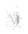
- FIG. 1 shows a first embodiment of a straining mechanism of the screw extruder, wherein (a) is a cross-sectional view corresponding to the AA cross-sectional view of FIG. 2, and (b) is a cross-sectional view corresponding to the BB cross-sectional view of FIG.
- FIG. 2C is a cross-sectional view corresponding to the CC cross-sectional view of FIG.
- FIG. 2 shows a second embodiment of the straining mechanism of the screw extruder, wherein (a) is a cross-sectional view corresponding to the AA cross-sectional view of FIG. 2, and (b) is a cross-sectional view corresponding to the BB cross-sectional view of FIG.
- FIG. 2C is a cross-sectional view corresponding to the CC cross-sectional view of FIG. 3 shows a third embodiment of the straining mechanism of the screw extruder, wherein (a) is a sectional view corresponding to the AA sectional view of FIG. 2, and (b) is a sectional view corresponding to the BB sectional view of FIG.
- FIG. 2C is a cross-sectional view corresponding to the CC cross-sectional view of FIG.
- FIG. 1 to 3 show an embodiment of a screw extruder equipped with the straining mechanism of the present invention.
- This screw extruder includes, as a feeder portion, a tapered cylindrical hopper portion 11 in which a material inlet 11a is formed, and a tapered cylindrical compression portion in which a material outlet 12a is formed at the tip following the hopper portion 11.
- the biaxial screw 2 in which the taper-shaped screw blades 21 are disposed is rotatably provided in the casing 1 having the structure 12. And this screw extruder arrange
- the straining mechanism 3 is slidable in the vertical direction along the discharge port 12a by the connecting member 31 that forms the material flow path 31a connected to the discharge port 12a of the casing 1 and the slide mechanism 32 including a cylinder.
- the screen includes a screen mesh 33, a breaker plate 34, and a backup plate 35 that are disposed so as to cut the material flow path 31a connected to the discharge port 12a.
- the screen mesh 33 is for removing foreign substances contained in the material, and can be used according to the properties of the material and the foreign substances to be removed.
- the breaker plate 34 is arranged on the back surface of the screen mesh 33 to support the screen mesh 33, and is formed with an opening 34a composed of a large number of small holes through which the material can pass.
- the openings 34a made of small holes have a hole diameter of about ⁇ 5 to 15 and each opening 34a is staggered in accordance with the shape of the oval discharge port 12a for a screw extruder equipped with a biaxial screw 2. It is preferable to form so that it may become a position.
- the thickness t 34 of the breaker plate 34 is set to about 5 to 20 mm.
- the backup plate 35 is for supporting the breaker plate 34 by being arranged on the back surface of the breaker plate 34.
- the backup plate 35 is larger than the opening ratio of the breaker plate 34. It has an aperture ratio.
- the large opening 35a is partitioned and formed by a lattice 35b in accordance with the shape of the oval discharge port 12a for the screw extruder provided with the biaxial screw 2.
- the thickness t 35 of the backup plate 35 is set to 20 to 80 mm, preferably about 30 to 70 mm, depending on the required strength.
- the lattice 35b that partitions and forms the opening 35a of the backup plate 35 has a rectangular (rectangular) lattice shape as shown in the first embodiment of FIG. 3, as shown in the second embodiment of FIG. , A rhombus lattice shape.
- the lattice 35b has a rhombic lattice shape.
- the lattice 35b is divided so that the sides of the lattice 35b that partitions and forms the adjacent openings 35a are not positioned on a straight line.
- the support strength of the backup plate 35 can be increased.
- the lattice 35b that partitions and forms the opening 35a of the backup plate 35 can be formed in a lattice shape in which circular openings 35a are arranged in a staggered position as shown in the third embodiment of FIG. Even with this lattice shape, the stress is distributed and supported without concentrating on the lattice points, so that the support strength of the backup plate 35 can be increased.
- the area of the material flow path immediately before the screen mesh 33 (the material flow path 31a formed in the connecting member 31 connected to the discharge port 12a of the casing 1 is formed of a material flow path having a constant straight area. In the example, the same area as the discharge port 12a of the casing 1.
- the opening ratio of the breaker plate 34 is set to about 30 to 60%, and the opening ratio of the backup plate 35 is set to about 60 to 85%. As a result, the overall strength of the breaker plate 34 and the backup plate 35 can be increased while keeping the passage resistance of the material in the breaker plate 34 low.
- Table 1 shows the opening ratio of the breaker plate 34 and the opening ratio of the backup plate 35 with respect to the area of the material flow path immediately before the screen mesh 33 of the first to third embodiments.
- the screen mesh 33 and the breaker plate 34 are fitted into a recess formed in the backup plate 35, and are attached to the backup plate 35 by using any fixing means such as a pressing ring and a screw. Accordingly, it is possible to prevent the screen mesh 33 from being damaged or being displaced together with the breaker plate 34 during operation or when the screen mesh 33 is replaced.
- a seal member 36 is provided. ing.
- the breaker plate 34 and the backup plate 35 are formed of separate members so that the breaker plate 34 and the backup plate 35 can be easily and independently manufactured.
- the breaker plate 34 and the backup plate 35 may be formed of a single member. Thereby, the whole intensity
- all of the openings 34 a formed in the breaker plate 34 can pass through the opening 35 a formed in the backup plate 35.
- the material remaining on the breaker plate 34 can be prevented from being mixed into the next extruded material, and the maintenance of the apparatus can be simplified.
- the screen mesh 33 and the breaker plate 34 can be easily replaced by arranging the backup plate 35 on which the screen mesh 33 and the breaker plate 34 are mounted so as to be slidable in the vertical direction along the discharge port 12a.
- the sliding direction of the backup plate 35 by the slide mechanism 32 can be the horizontal direction, or the sliding operation can be performed manually.
- the strain training mechanism configured as described above and the screw extruder provided with the strain training mechanism have the following effects. (1) Since the strength against the extrusion pressure of the material is ensured by the backup plate 35, to reduce the thickness t 34 of the breaker plate 34 can be reduced passage resistance of the material, to reduce the pressure required for extrusion of the material, While reducing the load power of the apparatus and suppressing the heat generation of the material, it is possible to contribute to quality improvement by preventing the material from being altered due to a temperature rise. (2) Since the openings 34a and 35a are not provided at locations where the backup plate 35 contacts and supports the breaker plate 34, the opening area (opening ratio) decreases, but the throughput increases due to the reduction of the material passage resistance. .
- apparatus becomes large in size, if further ensure strength is required, without changing the thickness t 34 of the breaker plate 34, to ensure increased to strength the thickness of the small backup plate 35 of flow resistance of the material As a result, the decrease in the processing amount can be reduced.
- the difference in the passage resistance of the material due to the size of the apparatus becomes small, and it is easy to assume the processing capacity by scaling up from a small apparatus.
- the straining mechanism of the present invention and the screw extruder including the straining mechanism have been described based on the embodiment of the screw extruder including the biaxial screw 2 provided with the tapered screw blades 21.
- the present invention is not limited to the configuration described in the above-described embodiment.
- a screw extruder provided with a biaxial screw provided with straight screw blades or a screw provided with a uniaxial screw The configuration can be appropriately changed within a range not departing from the gist of the present invention, such as an extruder and an extruder other than a screw extruder.
- the strain extruder of the present invention and the screw extruder equipped with the strain mechanism are capable of reducing the material resistance in the breaker plate even in a large apparatus having a large processing capacity, thereby reducing the load on the apparatus. Since it is possible to suppress power generation and heat generation of the material and improve the processing capacity, it is suitable for the use of a straining mechanism used for removing foreign substances contained in the material and a screw extruder equipped with the straining mechanism. It can be used, and can also be applied to an extruder other than a screw extruder.
Landscapes
- Engineering & Computer Science (AREA)
- Mechanical Engineering (AREA)
- Chemical & Material Sciences (AREA)
- Chemical Kinetics & Catalysis (AREA)
- Extrusion Moulding Of Plastics Or The Like (AREA)
Abstract
処理能力が大きな大型の装置においても、ブレーカープレートにおける材料の通過抵抗を低く抑えることを可能にすることによって、装置の負荷電力及び材料の発熱を抑制し、処理能力を向上することができるようにしたストレーニング機構及びそのストレーニング機構を備えたスクリュー押出機を提供するため、スクリーンメッシュ33を支持するブレーカープレート34の背面側に、ブレーカープレート34の開口率よりも大きな開口率を有する、ブレーカープレート34を支持するバックアッププレート35を配設する。
Description
本発明は、ストレーニング機構及びそのストレーニング機構を備えたスクリュー押出機に関し、特に、ゴムや樹脂材料等の高粘度物質(以下、「材料」という。)中に混在する不純物や未分散物等の異物(以下、単に、「異物」という。)を除去することができるようにしたストレーニング機構及びそのストレーニング機構を備えたスクリュー押出機に関するものである。
従来、材料に含まれる異物を除去するストレーニング工程を実施するために、材料の排出口にスクリーンメッシュを装着したストレーニング機構を配設して押し出しを行うことによりスクリーンメッシュで材料に含まれる異物を除去するスクリュー押出機が使用されている(例えば、特許文献1~2参照。)。
ところで、このスクリュー押出機のストレーニング機構においては、例えば、図7に示すように、材料を押し出す際に材料を介して作用する大きな圧力によってスクリーンメッシュ33に目開きや損傷が生じることを防止するために、スクリーンメッシュ33の背面に、材料が通過できる多数の小孔からなる開口34aを形成したブレーカープレート34を配置し、このブレーカープレート34によってスクリーンメッシュ33を支持するようにしている。
しかしながら、従来のスクリュー押出機のストレーニング機構3は、処理能力が大きくなる(装置が大型化する)のに合わせて、材料がブレーカープレート34を通過する際の抵抗(以下、「材料の通過抵抗」という。)が大きくなり、このため、材料の押し出しに要する圧力が高くなり、装置の負荷電力が大きくなるとともに、材料の発熱が大きくなるという問題があった。
また、材料の押し出しに要する圧力が高くなれば、スクリュー押出機のスクリュー2とケーシング1のクリアランスからの材料の漏れ量が多くなり処理能力が低下する。特に、2軸スクリュー押出機では、スクリュー2とケーシング1のクリアランスに加えてスクリュー2間でも漏れが生じる。さらに、両スクリュー2の噛合わせによりケーシング1内に圧力分布を生じることにより、スクリュー2に曲げ力が作用して撓みを生じるため、スクリュー2とケーシング1のクリアランスを大きくする必要があり処理能力の低下が大きくなるという問題があった。
そして、処理能力が大きくなる(装置が大型化する)のに合わせて大きくなる材料の通過抵抗に対する強度確保のためにブレーカープレート34の厚みt34を大きくする必要があるが、ブレーカープレート34の厚みt34を大きくすると、材料の通過抵抗が大きくなり処理能力が低下するという問題がある。
また、装置のサイズによりブレーカープレート34の厚みt34を異ならせると、材料の押出量の効率が異なることとなり、小型の装置からのスケールアップによる処理能力の想定を行いにくいという問題がある。
本発明は、従来のスクリュー押出機のストレーニング機構の有する問題点に鑑み、処理能力が大きな大型の装置においても、ブレーカープレートにおける材料の通過抵抗を低く抑えることを可能にすることによって、装置の負荷電力及び材料の発熱を抑制し、処理能力を向上することができるようにしたストレーニング機構及びそのストレーニング機構を備えたスクリュー押出機を提供することを目的とする。
上記目的を達成するため、本発明のストレーニング機構は、材料の排出口にスクリーンメッシュを配設するようにしたストレーニング機構において、スクリーンメッシュを支持するブレーカープレートの背面側に、ブレーカープレートの開口率よりも大きな開口率を有する、ブレーカープレートを支持するバックアッププレートを配設するようにしたことを特徴とする。
この場合において、ブレーカープレートとバックアッププレートとを別部材で構成するようにすることができる。
また、ブレーカープレートとバックアッププレートとを1つの部材で構成するようにすることができる。
また、スクリーンメッシュの直前の材料流路の面積に対するブレーカープレートの開口率を30~60%に、バックアッププレートの開口率を60~85%に、それぞれ設定するようにすることができる。
また、ブレーカープレートに形成された開口のすべてが、バックアッププレートに形成された開口側に貫通するようにすることができる。
また、本発明のスクリュー押出機は、上記ストレーニング機構を備えるようにしたことを特徴とする。
本発明のストレーニング機構及びそのストレーニング機構を備えたスクリュー押出機によれば、スクリーンメッシュを支持するブレーカープレートの背面側に、ブレーカープレートの開口率よりも大きな開口率を有する、ブレーカープレートを支持するバックアッププレートを配設するようにすることにより、処理能力が大きくなる(装置が大型化する)のに合わせて大きくなる材料の通過抵抗を、ブレーカープレートの背面側に配設したブレーカープレートの開口率よりも大きな開口率を有するバックアッププレートにより支持することができ、これにより、強度確保のためにブレーカープレートの厚みを大きくする必要がなくすことができる。
これにより、処理能力が大きな大型の装置においても、ブレーカープレートにおける材料の通過抵抗を低く抑えることを可能にすることによって、装置の負荷電力及び材料の発熱を抑制し、処理能力を向上することができる。
これにより、処理能力が大きな大型の装置においても、ブレーカープレートにおける材料の通過抵抗を低く抑えることを可能にすることによって、装置の負荷電力及び材料の発熱を抑制し、処理能力を向上することができる。
また、ブレーカープレートとバックアッププレートとを別部材で構成するようにすることにより、ブレーカープレート及びバックアッププレートの製造を独立して簡易に行うことができる。
また、ブレーカープレートとバックアッププレートとを1つの部材で構成するようにすることにより、ブレーカープレート及びバックアッププレートの全体の強度を高めることができる。
また、スクリーンメッシュの直前の材料流路の面積に対するブレーカープレートの開口率を30~60%に、バックアッププレートの開口率を60~85%に、それぞれ設定するようにすることにより、ブレーカープレートにおける材料の通過抵抗を低く抑えるようにしながら、ブレーカープレート及びバックアッププレートの全体の強度を高めることができる。
また、ブレーカープレートに形成された開口のすべてが、バックアッププレートに形成された開口側に貫通するようにすることにより、ブレーカープレートの目詰まりをなくし、装置のメンテナンスを簡易化することができる。
以下、本発明のストレーニング機構及びそのストレーニング機構を備えたスクリュー押出機の実施の形態を、図面に基づいて説明する。
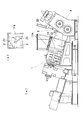
図1~図3に、本発明のストレーニング機構を備えたスクリュー押出機の一実施例を示す。
このスクリュー押出機は、フィーダ部として、材料の投入口11aを形成したテーパ筒状のホッパ部11と、このホッパ部11に続いて先端に材料の排出口12aを形成したテーパ筒状の圧縮部12とを備えたケーシング1内に、テーパ状のスクリュー羽根21を配設した2軸のスクリュー2を回転可能に設けるようにしている。
そして、このスクリュー押出機は、フィーダ部の材料の流れ方向下流側に、ストレーニング機構3を、その下流側に、2軸ロール4を、それぞれ配置することにより、材料のストレーニング及びシート状成形を連続して行うことができるようにしている。
このスクリュー押出機は、フィーダ部として、材料の投入口11aを形成したテーパ筒状のホッパ部11と、このホッパ部11に続いて先端に材料の排出口12aを形成したテーパ筒状の圧縮部12とを備えたケーシング1内に、テーパ状のスクリュー羽根21を配設した2軸のスクリュー2を回転可能に設けるようにしている。
そして、このスクリュー押出機は、フィーダ部の材料の流れ方向下流側に、ストレーニング機構3を、その下流側に、2軸ロール4を、それぞれ配置することにより、材料のストレーニング及びシート状成形を連続して行うことができるようにしている。
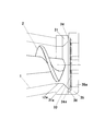
ところで、ストレーニング機構3は、ケーシング1の排出口12aに接続される材料流路31aを形成した接続部材31と、シリンダからなるスライド機構32によって排出口12aに沿って鉛直方向に摺動可能に配設した、より具体的には、排出口12aに接続される材料流路31aを縦断するように配設したスクリーンメッシュ33、ブレーカープレート34及びバックアッププレート35とから構成するようにしている。
ここで、スクリーンメッシュ33は、材料に含まれる異物を除去するためのもので、材料の性状、除去対象の異物に応じたものを用いることができる。
また、ブレーカープレート34は、スクリーンメッシュ33の背面に配置することによって、スクリーンメッシュ33を支持するためのもので、材料が通過できる多数の小孔からなる開口34aを形成するようにしている。
この小孔からなる開口34aは、孔径をφ5~15程度とし、2軸のスクリュー2を備えたスクリュー押出機のため長円形をしている排出口12aの形状に合わせて、各開口34aが千鳥位置となるように形成することが好ましい。
ブレーカープレート34の厚みt34は、5~20mm程度に設定するようにする。
この小孔からなる開口34aは、孔径をφ5~15程度とし、2軸のスクリュー2を備えたスクリュー押出機のため長円形をしている排出口12aの形状に合わせて、各開口34aが千鳥位置となるように形成することが好ましい。
ブレーカープレート34の厚みt34は、5~20mm程度に設定するようにする。
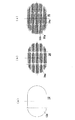
また、バックアッププレート35は、ブレーカープレート34の背面に配置することによってブレーカープレート34を支持するためのもので、材料が通過できる大きな開口35aを形成することにより、ブレーカープレート34の開口率よりも大きな開口率を有するようにしている。
この大きな開口35aは、2軸のスクリュー2を備えたスクリュー押出機のため長円形をしている排出口12aの形状に合わせて、格子35bによって区画、形成するようにしている。
バックアッププレート35の厚みt35は、必要される強度に応じて20~80mm、好ましくは、30~70mm程度に設定するようにする。
この大きな開口35aは、2軸のスクリュー2を備えたスクリュー押出機のため長円形をしている排出口12aの形状に合わせて、格子35bによって区画、形成するようにしている。
バックアッププレート35の厚みt35は、必要される強度に応じて20~80mm、好ましくは、30~70mm程度に設定するようにする。
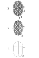
ところで、バックアッププレート35の開口35aを区画、形成する格子35bは、図3の第1実施例に示すような、方形(長方形)の格子形状のほか、図4の第2実施例に示すような、菱形の格子形状とすることができる。
このように、格子35bを、菱形の格子形状とすることにより、特に、隣接する開口35aを区画、形成する格子35bの辺が、一直線上に位置しないようにずらして配置することにより、応力が格子点に集中せずに分散して支持されることとなり、バックアッププレート35の支持耐力を高めることができる。
このように、格子35bを、菱形の格子形状とすることにより、特に、隣接する開口35aを区画、形成する格子35bの辺が、一直線上に位置しないようにずらして配置することにより、応力が格子点に集中せずに分散して支持されることとなり、バックアッププレート35の支持耐力を高めることができる。
また、バックアッププレート35の開口35aを区画、形成する格子35bは、図5の第3実施例に示すような、円形の開口35aを千鳥位置に配置した格子形状とすることができる。
この格子形状によっても、応力が格子点に集中せずに分散して支持されることとなり、バックアッププレート35の支持耐力を高めることができる。
この格子形状によっても、応力が格子点に集中せずに分散して支持されることとなり、バックアッププレート35の支持耐力を高めることができる。
ここで、スクリーンメッシュ33の直前の材料流路の面積(ケーシング1の排出口12aに接続される接続部材31に形成した材料流路31aがストレート状の面積が一定の材料流路からなる本実施例においては、ケーシング1の排出口12aと同面積。図6に示す第4実施例のように、材料流路31aがテーパ状の面積が拡大する材料流路からなる場合は、拡大部の面積。)に対するブレーカープレート34の開口率は、30~60%程度に、バックアッププレート35の開口率は、60~85%程度に、それぞれ設定するようにする。
これにより、ブレーカープレート34における材料の通過抵抗を低く抑えるようにしながら、ブレーカープレート34及びバックアッププレート35の全体の強度を高めることができる。
これにより、ブレーカープレート34における材料の通過抵抗を低く抑えるようにしながら、ブレーカープレート34及びバックアッププレート35の全体の強度を高めることができる。
表1に、第1~第3実施例のスクリーンメッシュ33の直前の材料流路の面積に対するブレーカープレート34の開口率及びバックアッププレート35の開口率を示す。

また、スクリーンメッシュ33及びブレーカープレート34は、バックアッププレート35に形成した窪み部に嵌め込まれ、押さえリング、ビス等の任意の固着手段を用いて、バックアッププレート35に装着されるようにしている。
これにより、運転時やスクリーンメッシュ33を交換する際に、スクリーンメッシュ33が損傷したり、ブレーカープレート34と共に位置ずれを起こすことを防止することができる。
これにより、運転時やスクリーンメッシュ33を交換する際に、スクリーンメッシュ33が損傷したり、ブレーカープレート34と共に位置ずれを起こすことを防止することができる。
また、ストレーニング機構3、具体的には、ケーシング1の排出口12aに接続される接続部材31とバックアッププレート35との隙間から材料が漏出しないようにするために、シール部材36を設けるようにしている。
ところで、本実施例においては、ブレーカープレート34とバックアッププレート35とを、別部材で構成するようにすることにより、ブレーカープレート34及びバックアッププレート35の製造を独立して簡易に行うことができるようにしているが、例えば、ブレーカープレート34とバックアッププレート35とを1つの部材で構成するようにすることもできる。
これにより、ブレーカープレート34及びバックアッププレート35の全体の強度を高めることができる。
これにより、ブレーカープレート34及びバックアッププレート35の全体の強度を高めることができる。
また、ブレーカープレート34に形成された開口34aのすべてが、バックアッププレート35に形成された開口35a側に貫通するようにすることができる。
これにより、ブレーカープレート34に残存した材料が、次の押出材料に混入することを防ぐとともに、装置のメンテナンスを簡易化することができる。
これにより、ブレーカープレート34に残存した材料が、次の押出材料に混入することを防ぐとともに、装置のメンテナンスを簡易化することができる。
また、スクリーンメッシュ33及びブレーカープレート34を装着したバックアッププレート35を、シリンダからなるスライド機構32によって排出口12aに沿って垂直方向に摺動可能に配設することにより、スクリーンメッシュ33の取り替えを容易に行うことができるようにしているが、スライド機構32によるバックアッププレート35の摺動方向は、水平方向とすることもでき、また、摺動動作を手動で行うようにすることもできる。
上記構成からなるストレーニング機構及びそのストレーニング機構を備えたスクリュー押出機は、以下の作用効果を奏する。
(1)材料の押し出し圧力に対する強度はバックアッププレート35により確保するため、ブレーカープレート34の厚みt34を小さくして材料の通過抵抗を低減することができ、材料の押し出しに要する圧力を小さくし、装置の負荷電力を小さくするとともに、材料の発熱を抑えることで温度上昇による材料に変質を生じさせない等、品質向上にも寄与できる。
(2)バックアッププレート35がブレーカープレート34に接触して支持する箇所には開口34a、35aを設けないため開口面積(開口率)は減少するが、材料の通過抵抗の低減により処理量は増加する。
(3)装置が大型化し、さらに強度確保が必要な場合は、ブレーカープレート34の厚みt34を変化させることなく、材料の通過抵抗の小さいバックアッププレート35の厚みを大きくして強度を確保することにより、処理量の低下を小さくできる。
(4)装置のサイズによる材料の通過抵抗の差異が小さくなり、小型の装置からのスケールアップによる処理能力の想定を行いやすい。
(1)材料の押し出し圧力に対する強度はバックアッププレート35により確保するため、ブレーカープレート34の厚みt34を小さくして材料の通過抵抗を低減することができ、材料の押し出しに要する圧力を小さくし、装置の負荷電力を小さくするとともに、材料の発熱を抑えることで温度上昇による材料に変質を生じさせない等、品質向上にも寄与できる。
(2)バックアッププレート35がブレーカープレート34に接触して支持する箇所には開口34a、35aを設けないため開口面積(開口率)は減少するが、材料の通過抵抗の低減により処理量は増加する。
(3)装置が大型化し、さらに強度確保が必要な場合は、ブレーカープレート34の厚みt34を変化させることなく、材料の通過抵抗の小さいバックアッププレート35の厚みを大きくして強度を確保することにより、処理量の低下を小さくできる。
(4)装置のサイズによる材料の通過抵抗の差異が小さくなり、小型の装置からのスケールアップによる処理能力の想定を行いやすい。
以上、本発明のストレーニング機構及びそのストレーニング機構を備えたスクリュー押出機について、テーパ状のスクリュー羽根21を配設した2軸のスクリュー2を備えたスクリュー押出機の実施例に基づいて説明したが、本発明は上記実施例に記載した構成に限定されるものではなく、例えば、ストレート状のスクリュー羽根を配設した2軸のスクリューを備えたスクリュー押出機や1軸のスクリューを備えたスクリュー押出機、さらには、スクリュー押出機以外の押出機にも適用することができる等、その趣旨を逸脱しない範囲において適宜その構成を変更することができるものである。
本発明のストレーニング機構及びそのストレーニング機構を備えたスクリュー押出機は、処理能力が大きな大型の装置においても、ブレーカープレートにおける材料の通過抵抗を低く抑えることを可能にすることによって、装置の負荷電力及び材料の発熱を抑制し、処理能力を向上することができることから、材料に含まれる異物を除去するために用いられるストレーニング機構及びそのストレーニング機構を備えたスクリュー押出機の用途に好適に用いることができるほか、スクリュー押出機以外の押出機にも適用することができる。
1 ケーシング
11 ホッパ部
11a 投入口
12 圧縮部
12a 排出口
2 スクリュー
21 スクリュー羽根
3 ストレーニング機構
31 接続部材
31a 材料流路
32 スライド機構
33 スクリーンメッシュ
34 ブレーカープレート
34a 開口
35 バックアッププレート
35a 開口
36 シール部材
4 2軸ロール
11 ホッパ部
11a 投入口
12 圧縮部
12a 排出口
2 スクリュー
21 スクリュー羽根
3 ストレーニング機構
31 接続部材
31a 材料流路
32 スライド機構
33 スクリーンメッシュ
34 ブレーカープレート
34a 開口
35 バックアッププレート
35a 開口
36 シール部材
4 2軸ロール
Claims (6)
- 材料の排出口にスクリーンメッシュを配設するようにしたストレーニング機構において、スクリーンメッシュを支持するブレーカープレートの背面側に、ブレーカープレートの開口率よりも大きな開口率を有する、ブレーカープレートを支持するバックアッププレートを配設するようにしたことを特徴とするストレーニング機構。
- ブレーカープレートとバックアッププレートとを別部材で構成するようにしたことを特徴とする請求項1に記載のストレーニング機構。
- ブレーカープレートとバックアッププレートとを1つの部材で構成するようにしたことを特徴とする請求項1に記載のストレーニング機構。
- スクリーンメッシュの直前の材料流路の面積に対するブレーカープレートの開口率を30~60%に、バックアッププレートの開口率を60~85%に、それぞれ設定してなることを特徴とする請求項1、2又は3に記載のストレーニング機構。
- ブレーカープレートに形成された開口のすべてが、バックアッププレートに形成された開口側に貫通するようにしてなることを特徴とする請求項1、2、3又は4に記載のストレーニング機構。
- 請求項1、2、3、4又は5に記載のストレーニング機構を備えたスクリュー押出機。
Priority Applications (4)
| Application Number | Priority Date | Filing Date | Title |
|---|---|---|---|
| CN201680038224.9A CN108025479B (zh) | 2015-07-16 | 2016-06-22 | 过滤机构及具备该过滤机构的螺杆挤出机 |
| EP16824226.1A EP3323589B1 (en) | 2015-07-16 | 2016-06-22 | Straining mechanism and screw extruder equipped with straining mechanism |
| KR1020187003897A KR102062359B1 (ko) | 2015-07-16 | 2016-06-22 | 스트레이닝 기구 및 그 스트레이닝 기구를 구비한 스크루 압출기 |
| US15/868,554 US11602882B2 (en) | 2015-07-16 | 2018-01-11 | Straining mechanism and screw extruder including straining mechanism |
Applications Claiming Priority (2)
| Application Number | Priority Date | Filing Date | Title |
|---|---|---|---|
| JP2015-142249 | 2015-07-16 | ||
| JP2015142249A JP6562504B2 (ja) | 2015-07-16 | 2015-07-16 | ストレーニング機構及びそのストレーニング機構を備えたスクリュー押出機 |
Related Child Applications (1)
| Application Number | Title | Priority Date | Filing Date |
|---|---|---|---|
| US15/868,554 Continuation US11602882B2 (en) | 2015-07-16 | 2018-01-11 | Straining mechanism and screw extruder including straining mechanism |
Publications (1)
| Publication Number | Publication Date |
|---|---|
| WO2017010246A1 true WO2017010246A1 (ja) | 2017-01-19 |
Family
ID=57758086
Family Applications (1)
| Application Number | Title | Priority Date | Filing Date |
|---|---|---|---|
| PCT/JP2016/068468 Ceased WO2017010246A1 (ja) | 2015-07-16 | 2016-06-22 | ストレーニング機構及びそのストレーニング機構を備えたスクリュー押出機 |
Country Status (6)
| Country | Link |
|---|---|
| US (1) | US11602882B2 (ja) |
| EP (1) | EP3323589B1 (ja) |
| JP (1) | JP6562504B2 (ja) |
| KR (1) | KR102062359B1 (ja) |
| CN (1) | CN108025479B (ja) |
| WO (1) | WO2017010246A1 (ja) |
Cited By (1)
| Publication number | Priority date | Publication date | Assignee | Title |
|---|---|---|---|---|
| WO2022202096A1 (ja) * | 2021-03-26 | 2022-09-29 | ポリプラスチックス株式会社 | 熱可塑性樹脂組成物の製造方法 |
Families Citing this family (4)
| Publication number | Priority date | Publication date | Assignee | Title |
|---|---|---|---|---|
| US10933572B2 (en) * | 2015-07-29 | 2021-03-02 | The Boeing Company | 2-stage extrusion apparatus and method of extrusion |
| US11260570B2 (en) * | 2018-05-07 | 2022-03-01 | PSI-Polymer Systems, Inc. | Filtration apparatuses and screen changer devices for polymer processing and related methods |
| US20200238568A1 (en) * | 2019-01-30 | 2020-07-30 | Corning Incorporated | Homogenizer and screen support for extrusion |
| KR102693125B1 (ko) * | 2024-01-24 | 2024-08-08 | (주) 미라이후손관거 | 압출기용 브레이커 플레이트 |
Citations (4)
| Publication number | Priority date | Publication date | Assignee | Title |
|---|---|---|---|---|
| JPS54117560A (en) * | 1978-02-09 | 1979-09-12 | Dart Ind Inc | Plastics injection molding method and apparatus for increasing dispersion of color and carbide in products |
| JPS57151111A (en) * | 1981-03-14 | 1982-09-18 | Fujikura Ltd | Method of producing plastic insulating cable |
| JP2000355042A (ja) * | 1999-06-15 | 2000-12-26 | Toagosei Co Ltd | 木目模様を有する物品の成形方法 |
| JP2011148188A (ja) * | 2010-01-21 | 2011-08-04 | Sumitomo Chemical Co Ltd | 溶融樹脂整流用ユニット |
Family Cites Families (13)
| Publication number | Priority date | Publication date | Assignee | Title |
|---|---|---|---|---|
| US3863001A (en) * | 1972-10-05 | 1975-01-28 | Jr Mario F Thumudo | Extrusion method for equalizing frictional material drag |
| US3856277A (en) * | 1973-09-28 | 1974-12-24 | Gloucester Eng Co Inc | Screen assembly for processing plastic |
| US4257901A (en) * | 1979-08-13 | 1981-03-24 | Western Electric Co., Inc. | Cleanable filter and method of cleaning same |
| JPS5837634Y2 (ja) * | 1980-05-19 | 1983-08-25 | 株式会社日本製鋼所 | 押出機の濾網受板 |
| JPS606050B2 (ja) * | 1981-03-14 | 1985-02-15 | 株式会社フジクラ | プラスチツク絶縁電線の製造方法 |
| US4918017A (en) * | 1989-02-03 | 1990-04-17 | Bridgestone/Firestone, Inc. | Screen assembly for screening elastomeric material |
| JPH05245906A (ja) | 1992-03-02 | 1993-09-24 | Sumitomo Electric Ind Ltd | プラスチック押出機 |
| US5507498A (en) * | 1993-10-13 | 1996-04-16 | Synergy Extrusion Technologies, Inc. | Sealing device for polymer filtration apparatus |
| WO1996001178A1 (en) * | 1994-07-01 | 1996-01-18 | Kabushiki Kaisha Kobe Seiko Sho | Filter medium for resin extruders and screen exchanger for resin extruders |
| US7276194B2 (en) * | 2003-08-29 | 2007-10-02 | Corning Incorporated | Method and apparatus for extruding a ceramic material |
| KR100929775B1 (ko) * | 2008-02-28 | 2009-12-03 | 엘에스전선 주식회사 | 수지 흐름이 개선된 압출 헤드부를 가지는 압출기 |
| JP5928209B2 (ja) | 2012-07-12 | 2016-06-01 | 日産自動車株式会社 | プラスチック組成物の押出造粒装置 |
| JP5594501B1 (ja) * | 2013-04-11 | 2014-09-24 | 株式会社昇竜建設 | ゲルプレートの小片化・分注装置及び小片化・分注方法 |
-
2015
- 2015-07-16 JP JP2015142249A patent/JP6562504B2/ja active Active
-
2016
- 2016-06-22 EP EP16824226.1A patent/EP3323589B1/en active Active
- 2016-06-22 KR KR1020187003897A patent/KR102062359B1/ko active Active
- 2016-06-22 WO PCT/JP2016/068468 patent/WO2017010246A1/ja not_active Ceased
- 2016-06-22 CN CN201680038224.9A patent/CN108025479B/zh active Active
-
2018
- 2018-01-11 US US15/868,554 patent/US11602882B2/en active Active
Patent Citations (4)
| Publication number | Priority date | Publication date | Assignee | Title |
|---|---|---|---|---|
| JPS54117560A (en) * | 1978-02-09 | 1979-09-12 | Dart Ind Inc | Plastics injection molding method and apparatus for increasing dispersion of color and carbide in products |
| JPS57151111A (en) * | 1981-03-14 | 1982-09-18 | Fujikura Ltd | Method of producing plastic insulating cable |
| JP2000355042A (ja) * | 1999-06-15 | 2000-12-26 | Toagosei Co Ltd | 木目模様を有する物品の成形方法 |
| JP2011148188A (ja) * | 2010-01-21 | 2011-08-04 | Sumitomo Chemical Co Ltd | 溶融樹脂整流用ユニット |
Non-Patent Citations (1)
| Title |
|---|
| See also references of EP3323589A4 * |
Cited By (1)
| Publication number | Priority date | Publication date | Assignee | Title |
|---|---|---|---|---|
| WO2022202096A1 (ja) * | 2021-03-26 | 2022-09-29 | ポリプラスチックス株式会社 | 熱可塑性樹脂組成物の製造方法 |
Also Published As
| Publication number | Publication date |
|---|---|
| EP3323589A4 (en) | 2019-05-08 |
| US11602882B2 (en) | 2023-03-14 |
| EP3323589B1 (en) | 2021-11-10 |
| JP6562504B2 (ja) | 2019-08-21 |
| KR102062359B1 (ko) | 2020-01-03 |
| CN108025479A (zh) | 2018-05-11 |
| US20180133947A1 (en) | 2018-05-17 |
| JP2017024194A (ja) | 2017-02-02 |
| CN108025479B (zh) | 2021-05-25 |
| EP3323589A1 (en) | 2018-05-23 |
| KR20180028494A (ko) | 2018-03-16 |
Similar Documents
| Publication | Publication Date | Title |
|---|---|---|
| JP6562504B2 (ja) | ストレーニング機構及びそのストレーニング機構を備えたスクリュー押出機 | |
| JP5905453B2 (ja) | 高粘性の媒体用の濾過装置 | |
| CN105682875A (zh) | 校正挤压件弓曲的装置和方法 | |
| JP6312203B2 (ja) | 2軸押出機 | |
| JP5984186B2 (ja) | 2軸押出機 | |
| US20210046425A1 (en) | Ceramic filter membrane module | |
| CN106457644A (zh) | 双螺杆挤出机 | |
| JP2010284832A (ja) | 濾過装置 | |
| CN108621398A (zh) | 一种模头可更换的挤出机模具 | |
| EP2930004B1 (en) | Vent assembly device for twin-screw extruder | |
| CN109278227A (zh) | 增强型全氟离子交换膜的二次流延机构 | |
| JP2009160935A (ja) | 特にプラスチック処理設備用のフルイド濾過装置 | |
| CN111298498B (zh) | 一种多孔隔筛及其设计方法 | |
| CN104085098A (zh) | 一种排气式挤出机排气段螺杆 | |
| US20160001485A1 (en) | Extruder filter replacement and backwash structure | |
| CN206344328U (zh) | 一种造粒机的模头装置 | |
| JP6759707B2 (ja) | スクリュー、押出機およびミキシングデバイス | |
| JP5188588B2 (ja) | ゲル低減方法 | |
| CN218795162U (zh) | 一种静态混合器 | |
| JP4785737B2 (ja) | 合成エラストマーの乾燥に使用する可変ダイ | |
| CN111330333B (zh) | 一种圆弧形多孔隔筛 | |
| CN215943631U (zh) | 一种挤塑机冷却水槽用阻水装置 | |
| CN204414353U (zh) | 一种真空练泥机 | |
| CN204339986U (zh) | 真空练泥机初练仓孔板 | |
| JP5601444B2 (ja) | ガラス薄片の製造方法とその製造装置 |
Legal Events
| Date | Code | Title | Description |
|---|---|---|---|
| 121 | Ep: the epo has been informed by wipo that ep was designated in this application |
Ref document number: 16824226 Country of ref document: EP Kind code of ref document: A1 |
|
| DPE1 | Request for preliminary examination filed after expiration of 19th month from priority date (pct application filed from 20040101) | ||
| NENP | Non-entry into the national phase |
Ref country code: DE |
|
| ENP | Entry into the national phase |
Ref document number: 20187003897 Country of ref document: KR Kind code of ref document: A |
|
| WWE | Wipo information: entry into national phase |
Ref document number: 2016824226 Country of ref document: EP |