WO2017010416A1 - 圧力センサ - Google Patents
圧力センサ Download PDFInfo
- Publication number
- WO2017010416A1 WO2017010416A1 PCT/JP2016/070237 JP2016070237W WO2017010416A1 WO 2017010416 A1 WO2017010416 A1 WO 2017010416A1 JP 2016070237 W JP2016070237 W JP 2016070237W WO 2017010416 A1 WO2017010416 A1 WO 2017010416A1
- Authority
- WO
- WIPO (PCT)
- Prior art keywords
- diaphragm
- heat receiving
- pressure sensor
- axis
- area
- Prior art date
- Legal status (The legal status is an assumption and is not a legal conclusion. Google has not performed a legal analysis and makes no representation as to the accuracy of the status listed.)
- Ceased
Links
Images






Classifications
-
- G—PHYSICS
- G01—MEASURING; TESTING
- G01L—MEASURING FORCE, STRESS, TORQUE, WORK, MECHANICAL POWER, MECHANICAL EFFICIENCY, OR FLUID PRESSURE
- G01L23/00—Devices or apparatus for measuring or indicating or recording rapid changes, such as oscillations, in the pressure of steam, gas, or liquid; Indicators for determining work or energy of steam, internal-combustion, or other fluid-pressure engines from the condition of the working fluid
- G01L23/08—Devices or apparatus for measuring or indicating or recording rapid changes, such as oscillations, in the pressure of steam, gas, or liquid; Indicators for determining work or energy of steam, internal-combustion, or other fluid-pressure engines from the condition of the working fluid operated electrically
- G01L23/18—Devices or apparatus for measuring or indicating or recording rapid changes, such as oscillations, in the pressure of steam, gas, or liquid; Indicators for determining work or energy of steam, internal-combustion, or other fluid-pressure engines from the condition of the working fluid operated electrically by resistance strain gauges
-
- F—MECHANICAL ENGINEERING; LIGHTING; HEATING; WEAPONS; BLASTING
- F02—COMBUSTION ENGINES; HOT-GAS OR COMBUSTION-PRODUCT ENGINE PLANTS
- F02B—INTERNAL-COMBUSTION PISTON ENGINES; COMBUSTION ENGINES IN GENERAL
- F02B77/00—Component parts, details or accessories, not otherwise provided for
- F02B77/08—Safety, indicating, or supervising devices
- F02B77/085—Safety, indicating, or supervising devices with sensors measuring combustion processes, e.g. knocking, pressure, ionization, combustion flame
-
- G—PHYSICS
- G01—MEASURING; TESTING
- G01L—MEASURING FORCE, STRESS, TORQUE, WORK, MECHANICAL POWER, MECHANICAL EFFICIENCY, OR FLUID PRESSURE
- G01L19/00—Details of, or accessories for, apparatus for measuring steady or quasi-steady pressure of a fluent medium insofar as such details or accessories are not special to particular types of pressure gauges
- G01L19/06—Means for preventing overload or deleterious influence of the measured medium on the measuring device or vice versa
- G01L19/0681—Protection against excessive heat
-
- G—PHYSICS
- G01—MEASURING; TESTING
- G01L—MEASURING FORCE, STRESS, TORQUE, WORK, MECHANICAL POWER, MECHANICAL EFFICIENCY, OR FLUID PRESSURE
- G01L23/00—Devices or apparatus for measuring or indicating or recording rapid changes, such as oscillations, in the pressure of steam, gas, or liquid; Indicators for determining work or energy of steam, internal-combustion, or other fluid-pressure engines from the condition of the working fluid
- G01L23/08—Devices or apparatus for measuring or indicating or recording rapid changes, such as oscillations, in the pressure of steam, gas, or liquid; Indicators for determining work or energy of steam, internal-combustion, or other fluid-pressure engines from the condition of the working fluid operated electrically
-
- G—PHYSICS
- G01—MEASURING; TESTING
- G01L—MEASURING FORCE, STRESS, TORQUE, WORK, MECHANICAL POWER, MECHANICAL EFFICIENCY, OR FLUID PRESSURE
- G01L23/00—Devices or apparatus for measuring or indicating or recording rapid changes, such as oscillations, in the pressure of steam, gas, or liquid; Indicators for determining work or energy of steam, internal-combustion, or other fluid-pressure engines from the condition of the working fluid
- G01L23/08—Devices or apparatus for measuring or indicating or recording rapid changes, such as oscillations, in the pressure of steam, gas, or liquid; Indicators for determining work or energy of steam, internal-combustion, or other fluid-pressure engines from the condition of the working fluid operated electrically
- G01L23/10—Devices or apparatus for measuring or indicating or recording rapid changes, such as oscillations, in the pressure of steam, gas, or liquid; Indicators for determining work or energy of steam, internal-combustion, or other fluid-pressure engines from the condition of the working fluid operated electrically by pressure-sensitive members of the piezoelectric type
-
- F—MECHANICAL ENGINEERING; LIGHTING; HEATING; WEAPONS; BLASTING
- F02—COMBUSTION ENGINES; HOT-GAS OR COMBUSTION-PRODUCT ENGINE PLANTS
- F02F—CYLINDERS, PISTONS OR CASINGS, FOR COMBUSTION ENGINES; ARRANGEMENTS OF SEALINGS IN COMBUSTION ENGINES
- F02F1/00—Cylinders; Cylinder heads
- F02F1/24—Cylinder heads
Definitions
- the present disclosure relates to a pressure sensor that measures a pressure in a combustion chamber of an internal combustion engine.
- a pressure sensor As a pressure sensor, a metal shell attached to the engine head, a pressure receiving member having a diaphragm and a pressure receiving rod, a press screw screwed into the pressure receiving rod, and a piezoelectric element sandwiched between the head of the press screw and the metal shell.
- a sensor having a sensor has been proposed. When the diaphragm receives the combustion pressure, the diaphragm is pushed rearward, whereby a load is transmitted to the piezoelectric sensor through the pressure receiving rod. The piezoelectric sensor converts a change in load into a change in electrical output.
- a heat shielding plate is disposed on the front surface of the diaphragm.
- This disclosure discloses a technique that can reduce a measurement error by using a member for receiving heat.
- Application Example 1 A cylindrical casing, a diaphragm that is bonded to the distal end side of the casing via a bonding portion, expands in a direction intersecting the axis of the casing, and bends according to pressure received, and the casing
- a sensor unit disposed in the body and having an electrical characteristic that varies depending on the pressure, a connection unit that connects the diaphragm and the sensor unit, and a direct connection or indirect connection to the diaphragm that is disposed on the distal end side of the diaphragm
- a pressure sensor comprising: a heat receiving portion for receiving heat, On the cross section perpendicular to the axis, connect the minimum value of the area of the minimum inclusion area that is a virtual area that includes the cross section of the portion from the heat receiving portion to the diaphragm and has the minimum overall length of the contour.
- the measurement error can be reduced using the heat receiving portion.
- the measurement error can be reduced using the heat receiving portion.
- the measurement error can be further reduced using the heat receiving portion.
- the measurement error can be further reduced using the heat receiving portion.
- the measurement error can be further reduced using the heat receiving portion.
- the pressure sensor according to Application Example 1 includes a plate-shaped heat receiving plate, When the thickness of the heat receiving plate is t, A pressure sensor satisfying t ⁇ 0.21 mm.
- the measurement error can be reduced by using the heat receiving plate.
- the measurement error can be further reduced.
- the pressure sensor according to Application Example 1 The heat receiving part is A plate portion extending in a direction intersecting the axis; A side wall portion protruding from the edge of the plate portion toward the tip side; With The side wall portion is formed over the entire circumference of the edge of the plate portion, In the side wall portion, a plurality of through holes arranged along the edge of the plate portion are formed, The maximum value of the length in the direction parallel to the axis of the plurality of through holes is 0.3 mm or more, In the cross section of the side wall portion that is perpendicular to the axis and does not pass through the plurality of through holes, the outer peripheral length of the side wall portion is defined as an outer peripheral length C1, In the cross section of the side wall portion perpendicular to the axis and passing through the plurality of through holes, when the total length of the portions corresponding to the outer peripheral surface of the side wall portion is the wall length C2, (C2 / C1) ⁇ 0.6 is satisfied, Pressure sensor.
- the gas flows from the inner peripheral side of the side wall portion to the outer peripheral side through the plurality of through holes in the side wall portion.
- the gas flows from the through hole in the side wall portion toward the outer peripheral side, it is possible to suppress the carbon generated in the combustion chamber from flowing on the outer peripheral side of the side wall portion and flowing between the heat receiving portion and the diaphragm.
- the gas easily flows from the surface on the front end side of the plate portion to the through hole in the side wall portion, so that a decrease in the flow velocity of the gas flowing from the through hole to the outer peripheral side can be suppressed. Therefore, it can suppress that carbon flows in the outer peripheral side of a side wall part, and flows in between a heat receiving part and a diaphragm.
- the gas flow from the through hole toward the outer peripheral side is part of the entire circumference of the side wall portion. It is suppressed to be biased. Therefore, it can suppress appropriately that carbon flows on the outer peripheral side of a side wall part, and flows in between a heat receiving part and a diaphragm.
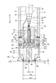
- FIG. 3 is an enlarged cross-sectional view of a tip portion of the pressure sensor 10.
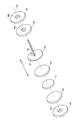
- FIG. 3 is an exploded perspective view of an element unit 50.
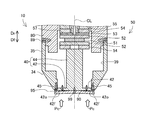
- FIG. It is explanatory drawing of operation
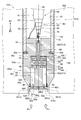
- FIG. 1 is an explanatory diagram showing a pressure sensor 10 as a first embodiment.
- the pressure sensor 10 of this embodiment is attached to an internal combustion engine and used to detect the pressure in the combustion chamber of the internal combustion engine.
- the pressure sensor 10 includes a cylindrical first metal fitting 20, a second metal fitting 80, a third metal fitting 35, a pressure receiving part 40, a heat receiving part 90, and an element part as main components. 50 and a cable 60.
- the central axis CL is the central axis of the pressure sensor 10.
- the central axis CL is also referred to as an axis line CL
- a direction parallel to the axis line CL is also referred to as an “axis direction”.
- the radial direction of the circle centered on the axis CL is also simply referred to as “radial direction”, and the circumferential direction of the circle centered on the axis CL is also simply referred to as “circumferential direction”.
- a direction from the first metal fitting 20 toward the pressure receiving portion 40 along the axis CL is referred to as a “front end direction Df”, and a direction opposite to the front end direction Df is referred to as a “rear end direction Dr”.
- the front end direction Df side is referred to as “front end side”
- the rear end direction Dr side is also referred to as “rear end side”.
- FIG. 1 shows a cross-sectional configuration on the left side of the axis CL of the portion on the distal end side of the pressure sensor 10.
- This cross section is a flat cross section (cross section cut along a plane) including the axis CL.
- FIG. 1 shows an external configuration of another part of the pressure sensor 10.
- the axis CL of the pressure sensor 10 is also the central axis of each of the first metal fitting 20, the second metal fitting 80, the third metal fitting 35, the pressure receiving part 40, the heat receiving part 90, and the element part 50.
- the first metal fitting 20, the second metal fitting 80, and the third metal fitting 35 have a cylindrical shape in which a cross section perpendicular to the axis CL (hereinafter also referred to as a transverse cross section) has an annular shape and extends in the axial direction.
- the 1st metal fitting 20, the 2nd metal fitting 80, and the 3rd metal fitting 35 are formed with stainless steel.
- other materials for example, steel such as low carbon steel, various metal materials may be adopted.
- the first metal fitting 20 is formed with a shaft hole 21 that is a through-hole centered on the axis CL.
- a screw portion 22 and a tool engagement portion 24 are provided on the outer peripheral surface of the first metal fitting 20 on the rear end side.
- the screw portion 22 includes a screw groove for fixing the pressure sensor 10 to the cylinder head of the internal combustion engine.
- the tool engaging portion 24 has an outer peripheral shape (for example, a hexagonal cross section) that engages with a tool (not shown) used for attaching and detaching the pressure sensor 10.
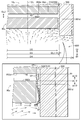
- FIG. 2 is an enlarged cross-sectional view of the distal end portion of the pressure sensor 10, specifically, the portion indicated as the region X in FIG.
- This cross section is a flat cross section including the axis CL.
- the second metal fitting 80 is disposed on the front end side of the first metal fitting 20, and is joined to the front end of the first metal fitting 20 via the joining portion 26.
- the joint portion 26 is a melted portion when the first metal fitting 20 and the second metal fitting 80 are welded (for example, laser welding) (hereinafter, the joint portion 26 is referred to as “welded portion 26” or “weld trace 26”). Also called).
- the joint portion 26 is a portion where the first metal fitting 20 and the second metal fitting 80 are integrated.
- the joint portion 26 includes a component of the first metal fitting 20 and a component of the second metal fitting 80.
- the third metal fitting 35 is disposed on the distal end side of the second metal fitting 80, and is joined to the second metal fitting 80 via a joining portion 89.
- the joint portion 89 is a melted portion when the second metal fitting 80 and the third metal fitting 35 are welded (for example, laser welding) (hereinafter, the joint portion 89 is referred to as “welded portion 89” or “weld trace 89”). Also called).
- the joint portion 89 is a portion where the second metal fitting 80 and the third metal fitting 35 are integrated.
- the joint portion 89 includes the component of the second metal fitting 80 and the component of the third metal fitting 35.
- a diameter-expanded portion 34 that increases in diameter from the front end side toward the rear end side is formed at the front end portion of the third metal fitting 35.
- the second metal fitting 80 is formed with a shaft hole 81 that is a through hole centered on the axis CL.
- the third metal fitting 35 is formed with a shaft hole 39 that is a through-hole centered on the axis CL.
- the shaft hole 21 of the first metal fitting 20, the shaft hole 81 of the second metal fitting 80, and the shaft hole 39 of the third metal fitting 35 form a continuous through hole communicating with the shaft hole 21 of the first metal fitting 20. Yes.
- the element portion 50 and the holding screw 32 are arranged in order from the front end side to the rear end side.
- a pressure receiving portion 40 is disposed in the shaft hole 39 of the third metal fitting 35.
- the pressure receiving unit 40 includes a diaphragm 42 and a rod 44.
- the diaphragm 42 is a substantially circular film centered on the axis line CL.
- the outer edge 42o of the diaphragm 42 is welded to the tip of the second metal fitting 80 over the entire circumference (for example, laser welding).
- a rod 44 is connected to the center of the surface on the rear end side of the diaphragm 42.
- the rod 44 is a cylindrical portion centering on the axis CL, and extends from the diaphragm 42 toward the rear end direction Dr.
- the element portion 50 is connected to the rear end portion 49 of the rod 44.
- the diaphragm 42 and the rod 44 are integrally formed using stainless steel (for example, forging or shaving).
- the diaphragm 42 and the rod 44 may be integrated by welding or the like.
- you may employ adopt other materials (For example, steel, such as low carbon steel, various metal materials).
- the heat receiving part 90 is joined to the surface on the front end side of the diaphragm 42 (for example, laser welding).
- the heat receiving unit 90 is a disk-shaped plate member centered on the axis CL (also referred to as a heat receiving plate).
- the heat receiving part 90 is joined to the diaphragm 42 (and thus the pressure receiving part 40) via the joining part 99.
- the joint portion 99 is a portion where the heat receiving portion 90 and the diaphragm 42 (and thus the pressure receiving portion 40) are melted during welding (hereinafter, the joint portion 99 is also referred to as “welded portion 99” or “weld mark 99”).
- Such a joint portion 99 is a portion where the heat receiving portion 90 and the diaphragm 42 are integrated. Further, the joint portion 99 includes a component of the heat receiving portion 90 and a component of the diaphragm 42. The joint 99 is formed at the center of the heat receiving part 90.
- the heat receiving portion 90 is formed using stainless steel in the present embodiment, but may be formed using other metals.
- the diaphragm 42 closes the shaft hole 39 at the tip of the third metal fitting 35.
- the diaphragm 42 is exposed in the combustion chamber of the internal combustion engine, and the surface 42f on the tip end direction Df side of the diaphragm 42 forms a pressure receiving surface.
- the pressure receiving surface 42 f can receive the pressure in the combustion chamber through the gap 95 between the diaphragm 42 and the heat receiving portion 90.
- the diaphragm 42 can receive a load corresponding to the pressure in the combustion chamber through the heat receiving portion 90.
- the rod 44 is displaced along the axis CL according to the deformation of the diaphragm 42, thereby transmitting a load corresponding to the pressure received by the diaphragm 42 to the element portion 50 on the rear end side.
- the diaphragm 42 is made thinner, the diaphragm 42 is more easily deformed, so that the sensitivity of the pressure sensor 10 can be increased.
- the holding screw 32 is attached to the rear end side of the shaft hole 81 of the second metal fitting 80.
- the holding screw 32 is formed with a shaft hole 36 that is a through-hole centered on the axis CL.
- a male screw 37 is formed on the outer peripheral surface of the holding screw 32.
- a female screw 88 corresponding to the male screw 37 of the holding screw 32 is formed on the inner peripheral surface of the rear end side portion of the shaft hole 81 of the second metal fitting 80.
- the holding screw 32 is screwed into the shaft hole 81 from the rear end side of the second metal fitting 80.
- the element unit 50 is sandwiched between the holding screw 32 and the rod 44 of the pressure receiving unit 40.
- the holding screw 32 applies a preload to the element unit 50.
- the holding screw 32 is made of stainless steel. However, other materials (for example, steel such as low carbon steel, various metal materials) may be adopted.
- the element unit 50 includes two electrodes 52, a piezoelectric element 51 sandwiched between the two electrodes 52, a pressing plate 54 disposed on the front end side of the front end electrode 52, and an electrode 52 on the rear end side.
- a lead portion 53, a pressing plate 54, and an insulating plate 55 are arranged in order in the rear end direction Dr.
- the pressing plate 54, the electrode 52, the piezoelectric element 51, the electrode 52, the lead portion 53, the pressing plate 54, and the insulating plate 55 are laminated in this order from the front end side to the rear end side. Yes.
- the surface on the rear end side of the insulating plate 55 is supported by the surface on the front end side of the press screw 32.
- the rear end portion 49 of the rod 44 is in contact with the front end surface of the front end holding plate 54.
- the piezoelectric element 51 is connected to the rod 44 via a tip-side electrode 52 and a pressing plate 54.
- the whole of the rod 44, the holding plate 54 on the distal end side, and the electrode 52 forms a connection portion 100 that connects the diaphragm 42 and the piezoelectric element 51.
- FIG. 3 is an exploded perspective view of the element unit 50.
- the piezoelectric element 51 and the electrode 52 are disk-shaped plate members centered on the axis CL.
- the holding plate 54 and the insulating plate 55 are annular plate-like members centered on the axis line CL.
- the piezoelectric element 51 is formed using quartz in the present embodiment, but a piezoelectric element formed of another material may be adopted.
- an electric charge is generated according to the load transmitted through the rod 44 from the pressure receiving portion 40 (FIG. 2).
- the piezoelectric element 51 outputs an electric charge (for example, an electric signal) corresponding to the load through the two electrodes 52.
- the piezoelectric element 51 has an electrical characteristic that varies depending on the pressure received by the pressure receiving unit 40.
- the electrode 52 and the pressing plate 54 are formed using stainless steel in the present embodiment, but may be formed using other metals.
- the insulating plate 55 is a member for insulating between the lead portion 53 and the holding screw 32 (FIG. 2). In this embodiment, the insulating plate 55 is formed of alumina, but may be formed of other types of insulating materials.
- the lead part 53 includes a disk part 57 that is a substantially disk-shaped plate member, and a terminal part 56 that extends from the center part of the disk part 57 toward the rear end direction Dr.
- the terminal portion 56 passes through the through hole 54h of the pressing plate 54 and the through hole 55h of the insulating plate 55 and protrudes toward the rear end direction Dr (FIG. 2).
- the lead portion 53 is formed using stainless steel in the present embodiment, but may be formed using other metals.
- the lead part 53 can be produced by punching out the shape of the disk part 57 and the terminal part 56 from a stainless steel flat plate, and then bending the part to be the terminal part 56.
- the lead part 53 is arranged so that the disk part 57 comes into surface contact with the electrode 52 and the terminal part 56 extends to the rear end side.
- the terminal portion 56 passes through the through hole 54 h at the center of the pressing plate 54 and the through hole 55 h at the center of the insulating plate 55.
- the rear end portion of the terminal portion 56 is disposed in the shaft hole 36 in a state of being separated from the inner wall surface of the shaft hole 36 of the presser screw 32.
- Each member (excluding the insulating plate 55) constituting the element unit 50 is disposed in the shaft hole 81 of the second metal fitting 80 so as to be separated from the inner wall surface of the second metal fitting 80.
- the electrode 52 on the rear end side of the piezoelectric element 51 is electrically connected to a lead portion 53 (in this embodiment, further a holding plate 54), and the first metal fitting 20, the second metal fitting 80, and the third metal fitting 35 are connected. It is electrically separated from.
- the electrode 52 on the distal end side of the piezoelectric element 51 is electrically connected to the third metal fitting 35 through the holding plate 54 on the distal end side, the rod 44, and the diaphragm 42.
- the pressing plate 54 is disposed not only on the rear end side but also on the front end side of the piezoelectric element 51.
- a cable 60 is arranged in the shaft hole 21 of the first metal fitting 20.
- the cable 60 is a member for transmitting the electric charge of the piezoelectric element 51 to an electric circuit (not shown) for detecting the combustion pressure of the internal combustion engine based on the electric charge of the piezoelectric element 51.
- noise is reduced by using a so-called shielded wire having a multilayer structure as the cable 60.
- the cable 60 includes an inner conductor 65, an insulator 64, a conductive coating 63, an outer conductor 62, and a jacket 61 arranged from the center toward the outer peripheral side.
- the inner conductor 65 is composed of a plurality of conductive wires.
- the outer side of the inner conductor 65 in the radial direction is surrounded by an insulator 64.
- a conductive coating 63 is provided on the outer peripheral surface of the insulator 64.
- An outer conductor 62 that is a mesh shield is provided on the outer side in the radial direction of the conductive coating 63.
- the outer peripheral surface of the outer conductor 62 is covered with a jacket 61.
- a cable including a plurality of members arranged coaxially in this way is also called a coaxial cable.
- the outer conductor 62 that is not covered by the jacket 61 is exposed from the portion covered by the jacket 61 toward the tip side at the tip portion of the cable 60.
- the insulator 64 that is not covered by the external conductor 62 is exposed from the portion where the external conductor 62 is exposed toward the tip side.
- the inner conductor 65 that is not covered by the insulator 64 is exposed from the portion where the insulator 64 is exposed toward the tip side.
- the internal conductor 65 exposed at the tip of the cable 60 is connected to the terminal portion 56 of the element portion 50 via a flat plate conductor 75 and a thin conductor 74.
- the flat conductor 75 is welded to the tip of the inner conductor 65, and the rear end of the thin conductor 74 wound in a coil shape is welded to the tip of the flat conductor 75,
- the distal end of the small diameter conductive wire 74 is welded to the rear end portion of the terminal portion 56.
- the flat conductive wire 75 and the thin conductive wire 74 can transmit the electric charge of the piezoelectric element 51 from the terminal portion 56 to the internal conductor 65.
- it replaces with the structure using the flat conducting wire 75 and the thin diameter conducting wire 74, and can employ
- the range including the entire terminal portion 56 and the tip of the thin wire 74 is Covered by a heat-shrinkable tube 72. Thereby, the reliability of the electrical insulation between the terminal part 56 and the holding screw 32 is improved.
- the integration of the lead portion 53 having the terminal portion 56 and the thin lead wire 74 by welding and the covering with the heat shrinkable tube 72 may be performed prior to the entire assembly.
- the ground conductor 76 extending from the distal end of the external conductor 62 to the distal end side is connected to the distal end portion of the external conductor 62.
- the grounding conductor 76 is composed of a stranded wire formed continuously from the outer conductor 62.
- the front end portion of the grounding conductor 76 is welded to the rear end portion of the holding screw 32.
- the outer conductor 62 is grounded through the grounding conductor 76, the holding screw 32, the second metal fitting 80, the third metal fitting 35, and the cylinder head of the internal combustion engine.
- the rod 44 is inserted into the shaft hole 39 from the distal end side of the third metal fitting 35.
- the diaphragm 42 and the third metal fitting 35 are welded (for example, laser welding) to form the joint portion 45.
- the joint portion 45 is a portion where the diaphragm 42 and the third metal fitting 35 are melted during welding (hereinafter, the joint portion 45 is also referred to as “welded portion 45” or “weld mark 45”).
- Such a joint portion 45 is a portion where the diaphragm 42 and the third metal fitting 35 are integrated. Further, the joint portion 45 includes a component of the diaphragm 42 and a component of the third metal fitting 35.
- the joint portion 45 joins the diaphragm 42 and the third metal fitting 35.
- the holding screw 32 is screwed into the shaft hole 81 from the rear end side of the second metal fitting 80.
- the holding screw 32 is temporarily fixed to the second metal fitting 80.
- the element unit 50 is inserted into the shaft hole 81 from the distal end side of the second metal fitting 80.
- the terminal portion 56 of the lead portion 53 of the element portion 50 is integrated with the small-diameter conductive wire 74 and the heat shrinkable tube 72 in advance.
- the thin diameter conducting wire 74 is inserted from the front end side of the shaft hole 36 of the holding screw 32, and the small diameter conducting wire 74 is drawn out from the rear end side of the shaft hole 36.
- the rear end surface of the insulating plate 55 is supported by the front end surface of the cap screw 32.
- the third metal fitting 35 is disposed on the distal end side of the second metal fitting 80.
- the element unit 50 is sandwiched between the holding screw 32 and the rod 44.
- the 3rd metal fitting 35 and the 2nd metal fitting 80 are welded, and the joined part 89 is formed.
- a preload is applied to the element portion 50 by rotating the holding screw 32 with respect to the second metal fitting 80. By adjusting the number of rotations of the holding screw 32, the preload can be adjusted.
- the rear end of the small-diameter conducting wire 74 drawn from the rear end side of the holding screw 32 (specifically, the shaft hole 36) and the tip of the internal conductor 65 are welded to the flat plate conducting wire 75. Further, the front end portion of the grounding conductor 76 and the rear end portion of the holding screw 32 are welded. Further, the cable 60 is passed through the shaft hole 21 of the first metal fitting 20, and the tip of the first metal fitting 20 and the second metal fitting 80 are welded to form the joint portion 26. Thereafter, molten rubber is injected into the shaft hole 21 of the first metal fitting 20 to fill the shaft hole 21 with a rubber layer (not shown), and the pressure sensor 10 is completed. By forming the rubber layer, the waterproof property in the pressure sensor 10 is improved and the vibration proof property is also improved. Note that molten resin may be injected into the shaft hole 21 instead of the molten rubber.
- the assembly order of the second metal fitting 80, the third metal fitting 35, the element portion 50, and the holding screw 32 other various orders can be adopted instead of the above order.
- the diaphragm 42 is welded to the third metal fitting 35
- the second metal fitting 80 is welded to the third metal fitting 35
- the element portion 50 is inserted into the shaft hole 81 from the rear end side of the second metal fitting 80
- the second metal fitting 35 is inserted.
- An order in which the holding screw 32 is screwed into the shaft hole 81 from the rear end side of 80 may be adopted.
- FIG. 4 is an explanatory diagram of the operation of the pressure sensor 10.
- the pressure receiving surface 42 f of the diaphragm 42 can receive the pressure Pc in the combustion chamber through the gap 95 between the diaphragm 42 and the heat receiving portion 90. Further, the diaphragm 42 can receive a load corresponding to the pressure Pc through the heat receiving portion 90.
- the diaphragm 42 bends (deforms) according to the pressure Pc in the combustion chamber. In the embodiment of FIG. 4, the diaphragm 42 bends in the axial direction.
- the rod 44 is displaced approximately parallel to the axis CL in accordance with the bending (deformation) of the diaphragm 42. As a result, the rod 44 transmits a load corresponding to the pressure Pc to the element unit 50.
- the heat receiving unit 90 is disposed on the tip side of the diaphragm 42, that is, on the combustion chamber side.
- the heat receiving unit 90 can receive heat from the combustion chamber instead of the diaphragm 42.
- the heat generated by the combustion of the fuel can be conducted to the surface on the front end side of the heat receiving unit 90 through the gas in the combustion chamber.
- high-temperature combustion gas can come into contact with the surface on the front end side of the heat receiving unit 90.
- the temperature of the heat receiving unit 90 (particularly, the tip side surface) can be increased. Since the diaphragm 42 is disposed on the rear end side of the heat receiving unit 90, it is less likely to receive heat from the combustion chamber than the heat receiving unit 90. Therefore, the thermal expansion of the diaphragm 42 is suppressed.
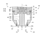
- FIG. 5 is an explanatory diagram of the operation of the pressure sensor 10x of the reference example.
- a plane cross section including an axis CL of a part of the tip side of the pressure sensor 10x is shown.
- the only difference from the pressure sensor 10 of the embodiment of FIG. 4 is that the heat receiving portion 90 is omitted.
- the configuration of the other part of the pressure sensor 10x is the same as the configuration of the corresponding part of the pressure sensor 10 of the embodiment.
- the pressure receiving surface 42f of the diaphragm 42 receives the pressure Pc in the combustion chamber, similarly to the pressure receiving surface 42f of the embodiment of FIG. Further, in the reference example of FIG. 5, unlike the embodiment of FIG. 4, the heat receiving portion 90 is omitted, so that the portion (for example, the pressure receiving surface 42 f) on the tip end direction Df side of the diaphragm 42 is from the combustion chamber. Receive heat. Thereby, the part by the side of the front-end
- the diaphragm 42 tends to extend toward the inner peripheral side (axis line CL side) due to thermal expansion.
- the thermal expansion of the diaphragm 42 can apply a force parallel to the axis CL to the rod 44.
- the thermal expansion of the pressure receiving surface 42 f of the diaphragm 42 applies a force F in the distal direction Df to the rod 44.
- the load applied to the element part 50 becomes small.
- the load applied to the element unit 50 can fluctuate greatly depending on the temperature of the combustion gas, so that the error of the signal from the element unit 50 increases.
- thermal expansion of the diaphragm 42 is suppressed by the heat receiving unit 90. Therefore, as compared with the reference example of FIG. 5, in the first embodiment, the error of the signal from the element unit 50 can be reduced.
- the thickness (plate thickness) of the heat-receiving unit 90 that is a plate-like member is t.
- the volume of the heat receiving unit 90 is larger than when the thickness t is small, and thus the amount of heat (heat capacity) that can be absorbed by the heat receiving unit 90 is large.
- the greater the thickness of the heat receiving portion 90 the more difficult the heat from the combustion chamber is transmitted to the diaphragm 42, so that the thermal expansion of the diaphragm 42 can be further suppressed. Signal error can be reduced.
- d be the minimum distance in the axial direction between the heat receiving portion 90 and the diaphragm 42. It can be said that the minimum distance d is the minimum distance in a direction parallel to the axis CL of the gap 95 between the heat receiving unit 90 and the diaphragm 42.
- the pressure receiving surface 42 f of the diaphragm 42 and the surface on the rear end side of the heat receiving unit 90 are directly joined. Therefore, the minimum distance d is zero.
- the minimum distance d is small, the high-temperature combustion gas is less likely to flow into the gaps 95 and 95a than when the minimum distance d is large.
- the minimum distance d is preferably 0.5 mm or less, and particularly preferably 0.3 mm or less.
- the surface 90f on the rear end side of the heat receiving portion 90 (that is, the surface facing the pressure receiving surface 42f of the diaphragm 42) and the direction perpendicular to the axis line are The angle formed is ⁇ .
- the rear end surface 90 f of the heat receiving portion 90 is slightly curved. For this reason, the angle ⁇ is 0 degrees at the position intersecting the axis CL, and increases as it goes radially outward from the axis CL.
- the angle ⁇ is small, high-temperature combustion gas is less likely to flow into the gap 95 than when the angle ⁇ is large.
- the absolute value of the angle ⁇ is preferably within 20 degrees.
- the absolute value of the angle ⁇ is within 20 degrees, the amount of heat transferred to the diaphragm can be further reduced by suppressing high-temperature combustion gas from flowing into the gap 95.
- the thermal expansion of the diaphragm 42 can be further suppressed, and as a result, the error of the signal from the element unit 50 can be reduced.
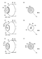
- FIG. 6 is an explanatory diagram of parameters Sn2, Sn, and Sd of the pressure sensor 10 of the first embodiment.
- 6 (A), 6 (C), and 6 (E) are perspective views of the distal end portion of the pressure sensor 10, and FIGS. 6 (B) and 6 (D) show the heat receiving portion 90 along the axis CL.
- FIG. 6F shows a projection view obtained by projecting the diaphragm 42 onto the projection plane perpendicular to the axis line CL.
- FIGS. 6C and 6E show a state where the heat receiving portion 90 is removed from the pressure receiving portion 40.
- FIG. 6 (A) and FIG. 6 (B) show the heat receiving area Sn2.
- the heat receiving area Sn2 is the entire area of the heat receiving unit 90 in the projection view of FIG.
- the area of the surface on the tip direction Df side of the heat receiving portion 90 corresponds to the heat receiving area Sn2.
- the heat receiving area Sn ⁇ b> 2 indicates an area of a region where heat from the combustion chamber can be received instead of the diaphragm 42.
- connection area Sn shows the connection area Sn.
- the connection area Sn includes a cross section of a portion from the heat receiving portion 90 to the diaphragm 42 (hereinafter also referred to as a target portion) on a cross section perpendicular to the axis CL, and a virtual region where the total length of the contour is minimized. Is the minimum value of the area of the minimum inclusion region.
- the connection area Sn is the area of the minimum inclusion region at a specific axial position.
- the position in the specific axial direction is a position where the minimum inclusion region in the cross section perpendicular to the axis CL is the smallest among the positions in the axial direction in the range from the heat receiving unit 90 to the diaphragm 42.
- region in a specific cross section is a virtual area
- the minimum inclusion region is also called a convex hull.
- the minimum inclusion area is one continuous area. The area of such a minimum inclusion region can vary depending on the position of the cross section in the axial direction.
- the connection area Sn is the minimum value of the area of the minimum inclusion region that can change according to the position of the cross section.
- the part from the heat receiving part 90 to the diaphragm 42 includes the heat receiving part 90, the diaphragm 42, and a part connecting the heat receiving part 90 and the diaphragm 42.
- the heat receiving portion 90 is directly connected to the diaphragm 42 by the joint portion 99, and therefore the portion connecting the heat receiving portion 90 and the diaphragm 42 is the heat receiving portion 90 of the joint portion 99.
- This is a portion between the rear end surface and the front end surface of the diaphragm 42.
- the connection area Sn that is, the minimum area of the minimum inclusion region is the connection surface between the heat receiving unit 90 and the diaphragm 42 (that is, the heat receiving unit 90) in the cross section from the heat receiving unit 90 to the diaphragm 42.
- connection portion 93 shows a connection portion 93 joined to the diaphragm 42 on the surface on the rear end side of the heat receiving portion 90.
- FIG. The connection portion 93 corresponds to a cross section of a joint portion 99 (FIG. 2) that joins the heat receiving portion 90 and the diaphragm 42.
- the area of the minimum inclusion region 94 including the connection portion 93 is the connection area Sn.
- the connection portion 43 in FIG. 6C is a portion corresponding to the connection portion 93 in the diaphragm 42.
- the heat receiving unit 90 can be thermally expanded by receiving heat from the combustion chamber (that is, can be deformed).
- the connection part 93 with the diaphragm 42 is large in the heat receiving unit 90, that is, when the connection area Sn is large, the deformation of the heat receiving unit 90 is easily transmitted to the diaphragm 42.
- the diaphragm 42 is deformed due to the deformation of the heat receiving unit 90, an unintended load can be applied to the element unit 50 due to the deformation of the diaphragm 42. Therefore, the smaller the connection area Sn, the smaller the error of the signal from the element unit 50.
- FIGS. 6E and 6F show the diaphragm effective area Sd (hereinafter also simply referred to as “effective area Sd”).
- the effective area Sd is an area of a region 46 surrounded by the joint 45 in the projection view of FIG.
- the inner peripheral side contour 45i of the joint portion 45 (that is, the contour 45i of the region 46) is the inner peripheral side of the joint portion 45 on the surface of the diaphragm 42 connected to the third metal fitting 35.
- a contour is employed.
- the contour on the inner peripheral side of the joint 45 on the rear end surface of the diaphragm 42 corresponds to the contour 45i of the region 46.
- the joint 45 that joins the diaphragm 42 and the third metal fitting 35 is annular in the projection view of FIG. Therefore, the part in the area
- the ratio (Sn2 / Sd) is, for example, preferably 0.8 or more, more preferably 0.9 or more, and particularly preferably 1 or more.
- the upper limit of the ratio Sn2 / Sd is preferably determined so that the heat receiving portion 90 does not contact the mounting hole of the cylinder head.
- the ratio Sn2 / Sd is preferably 1.2 or less.
- a sample sensor and a target pressure sensor (also referred to as a “target sensor”) were attached to the same cylinder (ie, combustion chamber) of the internal combustion engine. Then, by operating the internal combustion engine, a pressure waveform was obtained from each of the sample sensor and the target sensor.
- a target sensor also referred to as a “target sensor”
- an in-line four-cylinder engine with a displacement of 1.3 L and a natural intake air was used.
- the internal combustion engine was operated under the condition that the maximum pressure in the combustion chamber was 20 MPa.
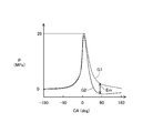
- FIG. 7 is a graph showing an example of a pressure waveform measured by the pressure sensor in the first evaluation test.
- the horizontal axis represents the crank angle CA, and the vertical axis represents the pressure (unit: kPa).
- a crank angle CA of zero degrees indicates a top dead center.
- a reference graph G1 and a sample graph G2 are shown.
- the reference graph G1 shows the pressure measured by the target sensor.
- the sample graph G2 shows the pressure measured by the pressure sensor sample.
- the pressure G2 measured by the pressure sensor sample may be different from the pressure G1 measured by the target pressure sensor (in the example of FIG. 7, the crank angle CA is zero to 180 degrees). Within range).
- the target pressure sensor is adjusted in advance so that the pressure can be measured with sufficiently good accuracy.
- the sample pressure G2 and the target pressure G1 were measured over five cycles. The difference between the two pressures G1 and G2 at the same timing was calculated. The maximum difference Em (FIG. 7) was specified for each cycle. The average value of the five maximum differences Em was calculated as the pressure error Ep of the pressure sensor of the sample.
- Evaluation results are as shown in Table 1.
- the evaluation of the sample with the heat receiving portion 90 having a thickness t of 0.1 mm is “B”, and the thickness t of the heat receiving portion 90 is
- the evaluation of samples of 0.2 mm or more, that is, 0.2 mm, 0.21 mm, and 0.3 mm was “A”.
- the evaluation of the samples having a thickness t of the heat receiving portion 90 of 0.2 mm or less, that is, 0.1 mm or 0.2 mm is “B”.
- the evaluation of the samples with the heat receiving portion 90 having a thickness t of 0.21 mm or more, that is, 0.21 mm and 0.3 mm was “A”.
- the thickness t of the heat receiving portion 90 is 0.21 mm or more (t ⁇ 0.21 mm), and the ratio (Sn / Sd) is 0.25 or less ((Sn / Sd) ⁇ 0.25), that is, in the range surrounded by the dotted line in Table 1, it was found that the pressure error Ep can be made sufficiently small.
- the reason for this is as follows. As described above, since the thermal expansion of the diaphragm 42 is suppressed as the thickness t of the heat receiving unit 90 is increased, the pressure error Ep is reduced. The smaller the ratio of the connection area Sn to the effective area Sd of the diaphragm 42a, that is, the smaller the ratio (Sn / Sd), the smaller the influence of the deformation of the heat receiving portion 90 on the deformation of the diaphragm 42. Ep becomes small. Therefore, a range in which the thickness t of the heat receiving unit 90 is relatively large and the ratio (Sn / Sd) is relatively small, specifically, t ⁇ 0.21 mm and (Sn / Sd) ⁇ 0.
- the pressure error Ep can be sufficiently reduced within a range satisfying .25. It is considered that the thickness t is more preferably in a larger range, for example, t ⁇ 0.3 mm. Further, it is considered that the ratio (Sn / Sd) is more preferably in a smaller range, for example, (Sn / Sd) ⁇ 0.24.
- FIG. 8 is an explanatory diagram of the pressure sensor 10a of the second embodiment.
- a plane cross section including an axis CL of the tip side portion of the pressure sensor 10 a is shown.
- the only difference from the first embodiment of FIG. 4 is that the rod 44a extends to the tip direction Df side from the diaphragm 42a and that the heat receiving portion 90 is joined to the tip portion of the rod 44a. It is.
- the structure of the other part of the pressure sensor 10a is the same as the structure of the corresponding part of the pressure sensor 10 of the first embodiment.
- the pressure receiving portion 40a includes a rod 44a, a diaphragm 42a, and a fixing portion 41a.
- the diaphragm 42a is an annular film centered on the axis CL.
- the outer peripheral edge 42ao of the diaphragm 42a is welded to the tip of the third metal fitting 35 over the entire circumference (for example, laser welding).
- the joint portion 45 that joins the diaphragm 42a and the third metal fitting 35 is a portion melted during welding.
- a fixed portion 41a is connected to the inner peripheral edge 42ai of the diaphragm 42a.
- the fixed portion 41a is a cylindrical portion centered on the axis CL, and extends from the edge 42ai of the diaphragm 42a toward the distal direction Df.
- the fixed portion 41a and the diaphragm 42a are integrally formed using stainless steel (for example, forging or shaving).
- the fixing portion 41a and the diaphragm 42a may be integrated by welding or the like.
- a rod 44a is inserted in the through hole on the inner peripheral side of the fixed portion 41a and the diaphragm 42a.
- the rod 44a is a columnar member centered on the axis CL.
- the rear end surface of the rod 44 a is in contact with the surface on the front end side of the pressing plate 54 on the front end side of the element unit 50.
- the distal end portion of the rod 44a protrudes from the fixed portion 41a toward the distal end side.
- the rod 44a is formed using stainless steel in the present embodiment, but may be formed using other metals.
- the fixing portion 41a and the rod 44a are welded over the entire circumference (for example, laser welding).
- the diaphragm 42a is connected to the rod 44a through the fixing portion 41a.
- the piezoelectric element 51 is connected to the rod 44 a via the tip-side electrode 52 and the pressing plate 54.
- the whole of the fixing portion 41 a, the rod 44 a, the holding plate 54 on the distal end side, and the electrode 52 forms a connection portion 100 a that connects the diaphragm 42 a and the piezoelectric element 51.
- the heat receiving portion 90 is joined to the tip surface of the rod 44a (for example, laser welding).
- the heat receiving part 90 is joined to the rod 44a via the joint 99a.
- the joint portion 99a is a portion where the heat receiving portion 90 and the rod 44a are melted during welding (hereinafter, the joint portion 99a is also referred to as “welded portion 99a” or “weld mark 99a”).
- Such a joint portion 99a is a portion where the heat receiving portion 90 and the rod 44a are integrated.
- the joint portion 99a includes a component of the heat receiving portion 90 and a component of the rod 44a.
- the heat receiving part 90 is connected to the diaphragm 42a via the rod 44a and the fixing
- the joint portion 99a is formed at the center of the heat receiving portion 90.
- the junction part 99a is formed over the whole end surface at the front end side of the rod 44a.
- the heat receiving portion 90 is formed using stainless steel in the present embodiment, but may be formed using other metals.
- the heat receiving unit 90 can receive heat from the combustion chamber instead of the diaphragm 42a. Since the diaphragm 42 a is disposed on the rear end side of the heat receiving unit 90, it is less likely to receive heat from the combustion chamber than the heat receiving unit 90. Therefore, the thermal expansion of the diaphragm 42a is suppressed. Compared to the reference example of FIG. 5, in the second embodiment, the error of the signal from the element unit 50 can be reduced.
- the thickness (plate thickness) of the heat receiving unit 90 which is a plate-like member, is t.
- the minimum distance in the axial direction between the heat receiving portion 90 and the diaphragm 42a is defined as d.
- the heat receiving portion 90 is disposed at a position away from the pressure receiving surface 42af, which is the surface of the diaphragm 42a on the tip direction Df side, in the tip direction Df. ing.
- the minimum distance d in the direction parallel to the axis CL of the gap 95a between the pressure receiving surface 42af and the heat receiving portion 90 is the surface on the rear end direction Dr side of the heat receiving portion 90 and the pressure receiving surface of the diaphragm 42a. It is the distance between 42af. Similar to the first embodiment, for example, the minimum distance d is preferably 0.5 mm or less, and particularly preferably 0.3 mm or less.
- the surface 90f on the rear end side of the heat receiving portion 90 (that is, the surface facing the pressure receiving surface 42af of the diaphragm 42a) and the direction perpendicular to the axis line are The angle formed is ⁇ .
- the surface 90f on the rear end side of the heat receiving unit 90 is a surface perpendicular to the axis CL, and thus the angle ⁇ is zero.
- the absolute value of the angle ⁇ is preferably within 20 degrees. In this way, it is possible to suppress the high-temperature combustion gas from flowing into the gap 95a, and to further suppress the thermal expansion of the diaphragm 42a, and to reduce the error of the signal from the element unit 50.
- FIG. 9 is an explanatory diagram of parameters Sn2, Sn, Sd of the pressure sensor 10a (FIG. 6) of the second embodiment.
- 9A, 9C, and 9E are perspective views of the tip of the pressure sensor 10a, and FIGS. 9B and 9D illustrate the heat receiving portion 90 with the axis CL.
- FIG. 9F shows a projection view obtained by projecting the diaphragm 42a onto the projection plane perpendicular to the axis line CL.
- FIG. 9C and FIG. 9E show a state where the heat receiving portion 90 is removed from the rod 44a.
- FIG. 9 (A) and FIG. 9 (B) show the heat receiving area Sn2.
- the heat receiving area Sn2 is the entire area of the heat receiving unit 90 in the projection view of FIG. 9B.
- the area of the surface on the tip direction Df side of the heat receiving portion 90 corresponds to the heat receiving area Sn2.
- the larger the heat receiving area Sn2 the more the thermal expansion of the diaphragm 42a is suppressed, that is, the error of the signal from the element unit 50 is reduced.
- connection area Sn shows the connection area Sn.
- the heat receiving portion 90 (FIG. 8) is indirectly connected to the diaphragm 42a via the rod 44a and the fixing portion 41a (the heat receiving portion 90 and the rod 44a are directly connected by the joint portion 99a. Connected).
- the part from the heat receiving part 90 to the diaphragm 42a includes the heat receiving part 90, the diaphragm 42a, and a part connecting the heat receiving part 90 and the diaphragm 42a.
- the portion connecting the heat receiving portion 90 and the diaphragm 42a is a portion between the rear end surface of the heat receiving portion 90 and the front end surface of the rod 44a in the joint portion 99a, and the fixed portion 41a of the rod 44a.
- fixed part 41a are included.
- the connection area Sn that is, the minimum area of the minimum inclusion region is the smallest in the cross-section perpendicular to the axis CL in the axial direction range from the heat receiving unit 90 to the diaphragm 42a. It is the area of the minimum inclusion region in a specific cross section.
- connection portion 93a connected to the rod 44a on the surface on the rear end side of the heat receiving portion 90.
- FIG. This connection portion 93a corresponds to a cross section of a joint portion 99a (FIG. 6) that joins the heat receiving portion 90 and the rod 44a.
- the shape of the connection portion 93a is the same as the cross-sectional shape of the rod 44a, the area of the minimum inclusion region 94a including the connection portion 93a is the connection area Sn.
- connection portion 93a that is, the cross-sectional shape of the rod 44a
- the shape of the minimum inclusion region 94a is approximately the same as the shape of the connection portion 93a
- the connection area Sn Is approximately the same as the area of the connecting portion 93a (that is, the cross-sectional area of the joint 99a and hence the cross-sectional area of the rod 44a).
- the connection portion 43a in FIG. 9C is a portion corresponding to the connection portion 93a in the rod 44a.
- the heat receiving portion 90 receives the heat from the combustion chamber and can be thermally expanded (that is, can be deformed).
- the connection portion 93a of the heat receiving unit 90 is large, that is, when the connection area Sn is large, the deformation of the heat receiving unit 90 is easily transmitted to the diaphragm 42a. Therefore, the smaller the connection area Sn, the smaller the error of the signal from the element unit 50.
- the effective area Sd is an area of a region 46a surrounded by the joint 45 in the projection view of FIG.
- the inner peripheral side contour 45i of the joint portion 45 that is, the contour 45i of the region 46a
- the contour on the inner peripheral side of the joint 45 on the rear end surface of the diaphragm 42a corresponds to the contour 45i of the region 46a.
- the joint portion 45 that joins the diaphragm 42a and the third metal fitting 35 is annular in the projection view of FIG. Accordingly, a portion of the pressure receiving portion 40a (that is, the diaphragm 42a, the fixed portion 41a, and the rod 44a) in the region 46 surrounded by the joint portion 45 can be deformed according to the pressure in the combustion chamber.
- the effective area Sd is the entire area of the region 46 a surrounded by the joint portion 45.
- the thickness t of the heat receiving unit 90 is 0.21 mm or more (t ⁇ 0.21 mm) and the ratio (Sn / Sd) is 0. It is preferably 25 or less ((Sn / Sd) ⁇ 0.25). In this way, the pressure error Ep can be made sufficiently small.
- Evaluation test An evaluation test using samples of the pressure sensor 10 of FIG. 2 and the pressure sensor 10a of FIG. 8 will be described. In the evaluation test, an error in the pressure measurement result by the pressure sensors 10, 10a was evaluated. Samples of the pressure sensors 10 and 10a include the minimum distance d between the heat receiving unit 90 and the diaphragms 42 and 42a, the effective area Sd of the diaphragms 42 and 42a, the connection area Sn, and the heat receiving area Sn2 of the heat receiving unit 90. Multiple types of samples with different combinations were evaluated.
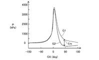
- FIG. 10 is a graph showing an example of a pressure waveform measured by the pressure sensor in the second evaluation test.
- the horizontal axis represents the crank angle CA, and the vertical axis represents the pressure (unit: kPa).
- a crank angle CA of zero degrees indicates a top dead center.
- a reference graph G1 and a sample graph G2 are shown.
- the reference graph G1 indicates the pressure measured by the target pressure sensor (also referred to as “target sensor”).
- the sample graph G2 shows the pressure measured by the pressure sensor sample.
- the sample sensor and the target sensor are attached to the same cylinder (ie, the combustion chamber) of the internal combustion engine, and the internal combustion engine is operated, so that the pressure from each of the sample sensor and the target sensor is measured.
- the waveform was acquired.
- the internal combustion engine an in-line four-cylinder engine with a displacement of 1.3 L and a natural intake air was used.
- the internal combustion engine was operated under conditions where the rotational speed was 1500 rpm and the shaft torque was 40 Nm.
- the pressure G2 measured by the pressure sensor sample may be different from the pressure G1 measured by the target pressure sensor (in the example of FIG. 10, the crank angle CA is from zero degrees to 180 degrees). Within range).
- the pressure G2 of any sample tended to be smaller than the target pressure G1.
- the target pressure sensor is adjusted in advance so that the pressure can be measured with sufficiently good accuracy.
- the sample pressure G2 and the target pressure G1 were measured over five cycles. The difference between the two pressures G1 and G2 at the same timing was calculated. The maximum difference Em (FIG. 10) was specified for each cycle. The average value of the five maximum differences Em was calculated as the pressure error Ep of the pressure sensor of the sample.
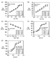
- FIG. 11A is a graph showing the results of the second evaluation test.
- the horizontal axis represents the ratio Sn / Sd, and the vertical axis represents the pressure error Ep (unit: kPa).
- One data point in each graph represents the pressure error Ep for one sample.
- the plurality of samples in FIG. 11A are samples of the pressure sensor 10a (for example, FIG. 6) of the second embodiment.
- the ratio Sn / Sd was distributed within a range of 0.05 to 0.35.
- the effective area Sd was any of 12 mm 2 , 16 mm 2 , and 20 mm 2 .
- the effective area Sd was adjusted by adjusting the inner diameter of the tip of the third metal fitting 35 and the outer diameter of the diaphragm 42a (the same applies to a plurality of samples in other graphs described later).
- the ratio Sn2 / Sd was 0.8 and the minimum distance d was 1 mm.
- the ratio Sn / Sd when the ratio Sn / Sd is 0.25 or less, a good pressure error Ep of 200 kPa or less can be realized.
- the ratio Sn / Sd that realized the pressure error Ep of 200 kPa or less was 0.05, 0.1, 0.15, 0.2, and 0.25.
- a preferred range (range between the lower limit and the upper limit) of the ratio Sn / Sd may be determined using the above five values. Specifically, any value of the above five values may be adopted as the upper limit of the preferable range of the ratio Sn / Sd.
- the ratio Sn / Sd is preferably 0.25 or less, and particularly preferably 0.1 or less.
- the ratio Sn / Sd may be 0.05 or more.
- the ratio Sn / Sd the smaller the influence of the deformation of the heat receiving portion 90 on the deformation of the diaphragm 42a, so the ratio Sn / Sd is less than 0.05, which is the minimum value among the above five values. It may be small. However, when the ratio Sn / Sd is small, the heat receiving unit 90 is easily detached from the pressure sensor. Therefore, the ratio Sn / Sd is preferably larger than zero, and is preferably determined so as to realize a connection strength such that the heat receiving unit 90 does not come off from the pressure sensor 10.
- FIG. 11B is a graph showing the results of the second evaluation test of another plurality of samples.
- the horizontal axis represents the ratio Sn / Sd, and the vertical axis represents the pressure error Ep (unit: kPa).
- the plurality of samples in FIG. 11B are samples of the pressure sensor 10a (for example, FIG. 6) of the second embodiment.
- the ratio Sn / Sd was distributed within a range of 0.05 to 0.35.
- the effective area Sd was any of 12 mm 2 , 16 mm 2 , and 20 mm 2 .
- the ratio Sn2 / Sd was 1, and the minimum distance d was 0.5 mm.
- the pressure error Ep was 60 kPa or less regardless of the ratio Sn / Sd.
- the plurality of samples in FIG. 11B can realize a better pressure error Ep than the plurality of samples in FIG. This is because the ratio Sn2 / Sd and the minimum distance d are adjusted to more preferable values (details will be described later).
- FIG. 11C is a graph showing the results of the second evaluation test of another plurality of samples.
- the horizontal axis indicates the ratio Sn2 / Sd, and the vertical axis indicates the pressure error Ep (unit is kPa).
- the plurality of samples in FIG. 11C are samples of the pressure sensor 10a (for example, FIG. 6) of the second embodiment.
- the ratio Sn2 / Sd was distributed within the range of 0.7 to 1.1.
- the effective area Sd was any of 12 mm 2 , 16 mm 2 , and 20 mm 2 .
- the ratio Sn / Sd was 0.25 and the minimum distance d was 1 mm.
- the ratio Sn / Sd was within the above preferred range.
- the minimum distance d is common to the plurality of samples in FIG.
- the outer diameter of the heat receiving portion 90 (FIG. 6) was the same as the outer diameter of the diaphragm 42a.
- the reason why the ratio Sn2 / Sd is larger than 1 is that the area of the joint 45 is excluded from the diaphragm effective area Sd.
- the outer diameter of the heat receiving portion 90 was smaller than the outer diameter of the diaphragm 42a.
- the larger the ratio Sn2 / Sd the smaller the pressure error Ep.
- the reason for this is as follows.
- the ratio Sn2 / Sd is large, the ratio of the portion hidden behind the heat receiving portion 90 in the diaphragm 42a is large, so that heat from the combustion chamber is difficult to be transmitted to the diaphragm 42a. Therefore, the larger the ratio Sn2 / Sd, the more the thermal expansion of the diaphragm 42a is suppressed, and hence the pressure error Ep can be reduced.
- the ratio Sn2 / Sd when the ratio Sn2 / Sd is 0.8 or more, a good pressure error Ep of 200 kPa or less can be realized.
- the ratio Sn2 / Sd that realized the pressure error Ep of 200 kPa or less was 0.8, 0.9, 1, 1.1.
- a preferable range (range between the lower limit and the upper limit) of the ratio Sn2 / Sd may be determined using the above four values. Specifically, any value of the above four values may be adopted as the lower limit of the preferable range of the ratio Sn2 / Sd.
- the ratio Sn2 / Sd is preferably 0.8 or more, and particularly preferably 1 or more.
- the ratio Sn2 / Sd may be 1.1 or less.
- the ratio Sn2 / Sd the more difficult the diaphragm 42a receives the heat from the combustion chamber. Therefore, even if the ratio Sn2 / Sd is larger than 1.1, which is the maximum value among the above four values. good.
- the upper limit of the ratio Sn2 / Sd is preferably determined so that the heat receiving portion 90 does not contact the mounting hole of the cylinder head.
- the ratio Sn2 / Sd is preferably 1.2 or less.
- FIG. 11D and FIG. 11E are graphs showing the results of the second evaluation test of another plurality of samples.
- the horizontal axis indicates the minimum distance d
- the vertical axis indicates the pressure error Ep (unit: kPa).
- the minimum distance d is 0.0, 0.3, 0.4, 0.5, 0.6, 0.7, 0.8. 1.0 or 1.2 (mm).
- the effective area Sd was any of 12 mm 2 , 16 mm 2 , and 20 mm 2 .
- the plurality of samples whose minimum distance d is 0.0 mm is the sample of the pressure sensor 10 (for example, FIG. 2) of the first embodiment.
- the plurality of samples whose minimum distance d is larger than 0.0 mm are samples of the pressure sensor 10a (for example, FIG. 6) of the second embodiment.
- the ratio Sn / Sd was common to the plurality of samples in FIGS. 11D and 11E and was 0.25. This ratio Sn / Sd was within the above preferred range.
- the ratio Sn2 / Sd was 1 in FIG. 11D and 0.8 in FIG. These ratios Sn2 / Sd were within the above preferred range.
- the pressure error Ep changes greatly between the range of d ⁇ 0.7 mm and the range of d ⁇ 0.5 mm.
- the pressure error Ep can be greatly improved.
- the minimum distance d may exceed 0.5 mm.
- the preferred ranges of the ratio Sn2 / Sd, the ratio Sn / Sd, and the minimum distance d have been described above.
- the preferred ranges of these three parameters can coexist with each other. Therefore, it is preferable to adopt a configuration in which one or more parameters arbitrarily selected from the three types of parameters are within a preferable range of each parameter as the configuration of the pressure sensor.
- a configuration in which (Sn2 / Sd) ⁇ 0.8 and (Sn / Sd) ⁇ 0.25 is adopted as in some of the samples in FIGS. 11 (A) and 11 (B). May be.
- one or more arbitrary conditions selected from the following three conditions may be satisfied.
- the effective areas Sd of the diaphragms 42 and 42a that achieved a good pressure error Ep were 12 mm 2 , 16 mm 2 , and 20 mm 2 .
- a preferable range (a range from the lower limit to the upper limit) of the effective area Sd may be determined using the above three values. Specifically, any value of the above three values may be employed as the lower limit of the preferable range of the effective area Sd.
- the effective area Sd may be 12 mm 2 or more.
- the effective area Sd may be 20 mm 2 or less. As shown in FIGS.
- the difference in the pressure error Ep is small between a plurality of samples having different effective areas Sd and the same other conditions. That is, the dependency of the pressure error Ep on the effective area Sd is small. Accordingly, the effective area Sd may be smaller than 12 mm 2, or may be greater than 20 mm 2.
- FIG. 12 is an explanatory diagram of the pressure sensor 10b according to the third embodiment.
- 12A shows a flat cross section including a part of the axis CL on the tip side of the pressure sensor 10b.
- FIGS. 12B and 12C show the heat receiving portion 90 on the projection plane perpendicular to the axis CL. The projection figure obtained by projecting is shown.
- the difference from the first embodiment shown in FIG. 4 is only that the joining portion 99b that joins the heat receiving portion 90 and the diaphragm 42 is annular when viewed in the axial direction.
- the joint portion 99b is a portion where the heat receiving portion 90 and the diaphragm 42 (and thus the pressure receiving portion 40) are melted during welding (hereinafter, the joint portion 99b is also referred to as “welded portion 99b” or “weld mark 99b”). Such a joint portion 99b is a portion where the heat receiving portion 90 and the diaphragm 42 are integrated. Further, the joint 99b includes the component of the heat receiving unit 90 and the component of the diaphragm 42.
- the configuration of the other part of the pressure sensor 10b is the same as the configuration of the corresponding part of the pressure sensor 10 of the first embodiment.
- FIG. 12B shows the connection portion 93b and the outline of the minimum inclusion region 94b including the connection portion 93b.
- the connection part 93 b is a part joined to the diaphragm 42 on the surface on the rear end side of the heat receiving part 90.
- the connecting portion 93b is hatched.
- the connection portion 93 b corresponds to a cross section of the joint portion 99 b on the surface on the rear end side of the heat receiving portion 90.
- the part (here junction part 99b) connected to the diaphragm 42 among the heat receiving parts 90 may be an annular part having a hole.
- connection area Sn indicates the minimum area of the portion where the deformation of the heat receiving portion is easily transmitted.
- the area of the minimum inclusion region 94b including the connection portion 93b is preferable to employ the area of the minimum inclusion region 94b including the connection portion 93b as the connection area Sn.
- the shape of the contour on the outer peripheral side of the connection portion 93b is substantially circular, so the shape of the contour of the minimum inclusion region 94b is approximately the same as the shape of the contour on the outer peripheral side of the connection portion 93b.
- the specific The minimum inclusion region in the cross section at the position of is a region surrounded by the outer contour (outer edge) of the annular cross section.
- a region corresponding to the connection area Sn is hatched.
- ratio Sn / Sd calculated using such connection area Sn exists in said preferable range.
- the thickness t of the heat receiving unit 90, the angle ⁇ of the heat receiving unit 90, the ratio Sn2 / Sd, the ratio Sn / Sd, and one or more parameters selected arbitrarily from the minimum distance d it is estimated that a favorable pressure error Ep can be realized by adopting a configuration in which each parameter is within the above preferable range.
- the thickness t of the heat receiving unit 90 is 0.21 mm or more (t ⁇ 0.21 mm) and the ratio (Sn / Sd ) Is preferably 0.25 or less ((Sn / Sd) ⁇ 0.25). In this way, the pressure error Ep can be made sufficiently small.
- the heat receiving portion 90 is directly connected to the diaphragm 42 by the joint portion 99b. Therefore, the minimum distance d is zero. Further, the rear end surface 90f of the heat receiving portion 90 is perpendicular to the axis line CL. Therefore, the angle ⁇ formed by the surface 90f on the rear end side of the heat receiving portion 90 and the direction perpendicular to the axis line CL is zero.
- FIG. 13 is an explanatory diagram of a pressure sensor 10c according to the fourth embodiment.
- a flat cross section including a part of the axis CL on the tip side of the pressure sensor 10c is shown.
- the difference from the second embodiment shown in FIG. 8 is that the heat receiving portion 90 and the rod 44c are formed by one member 120 (referred to as “heat receiving rod 120”).
- the structure of the other part of the pressure sensor 10c is the same as the structure of the corresponding part of the pressure sensor 10a of the second embodiment.
- the heat receiving rod 120 includes a heat receiving portion 90 and a rod 44c connected to the rear end side of the heat receiving portion 90.
- the shape of the heat receiving part 90 is the same as the shape of the heat receiving part 90 of FIG.
- the shape of the rod 44c is a shape in which a small diameter portion 48 having a small outer diameter is locally formed on a cylinder centering on the axis CL.
- the rod 44c is inserted into a through-hole on the inner peripheral side of the fixed portion 41a and the diaphragm 42a, and is welded to the fixed portion 41a.
- the small diameter part 48 is located between the heat receiving part 90 and the fixed part 41a.
- the heat receiving rod 120 is integrally formed as one member (for example, forging or shaving).
- the heat receiving rod 120 is formed using stainless steel in the present embodiment, it may be formed using other metals.
- the piezoelectric element 51 is connected to the rod 44c through the tip-side electrode 52 and the pressing plate 54.
- the whole of the fixing portion 41a, the rod 44c, the holding plate 54 on the distal end side, and the electrode 52 forms a connection portion 100c that connects the diaphragm 42a and the piezoelectric element 51.
- the heat receiving portion 90 is indirectly connected to the diaphragm 42a via the rod 44c and the fixing portion 41a.
- the part from the heat receiving part 90 to the diaphragm 42a includes the heat receiving part 90, the diaphragm 42a, and a part connecting the heat receiving part 90 and the diaphragm 42a.
- a portion connecting the heat receiving portion 90 and the diaphragm 42a includes a portion from a portion connected to the fixed portion 41a to a portion connected to the heat receiving portion 90 in the rod 44c, and the fixed portion 41a.
- the cross section in which the area of the minimum inclusion region in the cross section perpendicular to the axis CL at the position in the axial direction from the heat receiving portion 90 to the diaphragm 42a is the portion with the smallest outer diameter of the small diameter portion 48. It is a section which passes through.
- the connection area Sn that is, the minimum area of the minimum inclusion region is the area of the minimum inclusion region in the cross section of the minimum outer diameter portion of the small diameter portion 48 of the rod 44c (not shown).
- the heat receiving area Sn2, the effective area Sd, and the minimum distance d are calculated in the same manner as in the second embodiment of FIG.
- the thickness t of the heat receiving portion 90 is 0.21 mm or more (t ⁇ 0.21 mm) and the ratio (Sn / Sd ) Is preferably 0.25 or less ((Sn / Sd) ⁇ 0.25). In this way, the pressure error Ep can be made sufficiently small.
- connection area Sn is an area of a minimum inclusion region including a cross section of a portion between the surface on the rear end side of the heat receiving portion 90 and the end on the front end side of the fixing portion 41a in the rod 44c.
- the rear end surface 90f of the heat receiving unit 90 is perpendicular to the axis CL. Therefore, the angle ⁇ formed by the surface 90f on the rear end side of the heat receiving portion 90 and the direction perpendicular to the axis line CL is zero.
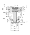
- FIG. 14 is an explanatory diagram of the pressure sensor 10d according to the fifth embodiment.
- This cross section is a flat cross section including the axis CL.
- the member composed of the second metal fitting 80, the third metal fitting 35, and the holding screw 32 in the pressure sensor 10 of FIG. 14 is formed by one tip metal fitting 30d.
- the tip metal fitting 30d is disposed on the tip end side of the first metal fitting 20, and is joined to the tip of the first metal fitting 20 via a joint portion 26d.
- the joint portion 26d is a melted portion during welding (for example, laser welding) between the first metal fitting 20 and the tip metal fitting 30d.
- a diameter-expanded portion 34d that increases in diameter from the front end side toward the rear end side is formed at the front end portion of the front end fitting 30d.
- the enlarged diameter portion 34d is in close contact with the seal surface 520 of the attachment hole 510 of the cylinder head 500 of the internal combustion engine.
- the end fitting 30d is formed with a shaft hole 31d which is a through-hole centered on the central axis CL.
- the shaft hole 31d includes a large inner diameter portion 35d and a small inner diameter portion 36d connected to the rear end side of the large inner diameter portion 35d and having an inner diameter smaller than the inner diameter of the large inner diameter portion 35d.
- a step portion 39d is provided between the large inner diameter portion 35d and the small inner diameter portion 36d.
- the step portion 39d forms a surface facing the tip direction Df side.
- a pressure receiving portion 40 and an element portion 50 similar to the pressure receiving portion 40 and the element portion 50 in FIG. 14 are arranged in order from the front end side to the rear end side.
- the pressure receiving part 40 is welded to the tip of the tip fitting 30d (for example, laser welding), and closes the shaft hole 31 at the tip of the tip fitting 30d.
- connection part 100 d that connects the diaphragm 42 and the piezoelectric element 51.
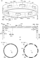
- FIG. 15 is an explanatory diagram of the heat receiving portion 90d.
- FIG. 15A shows a perspective view of the heat receiving portion 90d
- FIG. 15B shows a flat cross section including the axis CL of the heat receiving portion 90d.
- the heat receiving portion 90d includes a disc-shaped plate portion 93d centered on the axis CL, a cylindrical side wall portion 92d protruding from the outer peripheral edge 93do of the plate portion 93d toward the distal direction Df, and a central portion of the plate portion 93d.
- Column-shaped leg part 98d which protrudes in the rear end direction Dr side.
- the entire side wall portion 92d and plate portion 93d are also referred to as “main portion 91d”.
- the outer diameter of the leg portion 98d is smaller than the outer diameter of the main portion 91d.
- the side wall portion 92d is formed over the entire periphery of the edge 93do of the plate portion 93d.
- the side wall portion 92d is formed with a plurality of through holes 97d arranged along the edge 93do of the plate portion 93d (that is, arranged along the circumferential direction).
- the through hole 97d is a substantially rectangular hole surrounded by two inner surfaces perpendicular to the axis CL and two inner surfaces parallel to the axis CL.
- the size H1 in FIG. 15B is the size in the axial direction of the through hole 97d, and is the maximum value of the length (ie, size) in the direction parallel to the axial line CL of the plurality of through holes 97d.
- the size in the axial direction of one through hole 97d is the maximum value of the length of the line segment connecting the two points when a straight line parallel to the axis CL passes through two points on the inner surface of one through hole 97d. is there.
- the size H1 is the maximum value among the sizes in the axial direction of the plurality of through holes 97d. In the embodiment of FIG. 15B, the through hole 97d extends along the radial direction. Therefore, the size H1 is the same as the length of the through hole 97d in the direction parallel to the axis CL.
- FIGS. 15C and 15D show a cross section perpendicular to the axis CL of the side wall portion 92d.
- FIG. 15C shows the first cross section CS1 that does not pass through the plurality of through holes 97d
- FIG. 15D shows the second cross section CS2 that passes through the plurality of through holes 97d.
- the outer peripheral length C1 shown in FIG. 15C is the outer peripheral length of the side wall portion 92d in the first cross section CS1.
- the outer peripheral length C1 is the same as the peripheral length of the circle calculated from the outer diameter D2 of the heat receiving portion 90d.
- the wall length C2 shown in FIG. 15D is the total length of portions corresponding to the outer peripheral surface of the side wall portion 92d in the second cross section CS2.
- the wall length C2 is the sum of the lengths of the portions indicated by bold lines.
- the wall length C2 is the remainder obtained by subtracting the circumferential length of the through hole 97d from the outer peripheral length C1.
- the plurality of through holes 97d are arranged so as to be evenly distributed along the circumferential direction.
- the side wall portion 92d, the plate portion 93d, and the leg portion 98d are integrally formed using stainless steel (for example, forging or shaving). After forming two parts of the side wall part 92d, the plate part 93d, and the leg part 98d, or three parts separately, these parts may be integrated by welding or the like. Moreover, you may employ
- the heat receiving portion 90d is joined to the diaphragm 42 (and thus the pressure receiving portion 40) via the joining portion 99d.
- the joint part 99d is a part melted during welding of the heat receiving part 90d and the diaphragm 42 (and thus the pressure receiving part 40) (for example, laser welding).
- the joining part 99d is formed in the center part of the heat receiving part 90d.
- the heat receiving portion 90d is disposed in the mounting hole 510 of the cylinder head 500. Specifically, the heat receiving portion 90d is located inside the portion 530 on the tip end direction Df side of the attachment hole 510 (also referred to as “tip portion 530”). The outer peripheral surface 922d of the side wall portion 92d faces the inner peripheral surface of the tip portion 530 of the attachment hole 510.
- the element unit 50 includes two electrodes 52, a piezoelectric element 51 sandwiched between the two electrodes 52, a pressing plate 54 disposed on the front end side of the front end electrode 52, and an electrode 52 on the rear end side.
- a lead portion 53, a pressing plate 54, and an insulating plate 55 are arranged in order in the rear end direction Dr.
- the pressing plate 54, the electrode 52, the piezoelectric element 51, the electrode 52, the lead portion 53, the pressing plate 54, and the insulating plate 55 are laminated in this order from the front end side to the rear end side. Yes.
- the surface on the rear end side of the insulating plate 55 is supported by the step portion 39d of the tip fitting 30d.
- the rear end portion 49 of the rod 44 is in contact with the front end surface of the front end holding plate 54.
- the pressing plate 54 has a through-hole 54h centered on the axis CL.
- the rear end portion 49 of the rod 44 has a protruding portion that is inserted into the through hole 54h.
- the rear end surface of the projecting portion is in contact with the front surface of the front electrode 52.
- the piezoelectric element 51 is connected to the rod 44 via a tip-side electrode 52 and a pressing plate 54.
- the entirety of the rod 44, the pressing plate 54 on the distal end side, and the electrode 52 forms a connection portion 100d that connects the diaphragm 42 and the piezoelectric element 51.
- the element portion 50 When manufacturing the pressure sensor 10d, the element portion 50 is inserted into the shaft hole 31d (specifically, the large inner diameter portion 35d) from the distal end side of the distal end fitting 30d.
- the terminal portion 56 of the lead portion 53 of the element portion 50 is integrated with the small-diameter conductive wire 74 and the heat shrinkable tube 72 in advance.
- the thin diameter conducting wire 74 is inserted from the tip end side of the small inner diameter portion 36d of the tip fitting 30d, and the small diameter conducting wire 74 is drawn out from the rear end side of the small inner diameter portion 36d.
- the pressure receiving part 40 is disposed on the tip side of the element part 50.
- the edge 42o of the diaphragm 42 and the end fitting 30d are welded to form the joint portion 45.
- the length of the rod 44 is determined in advance so that an appropriate preload is applied to the element unit 50.
- the heat receiving portion 90d is welded to the diaphragm 42 to form 99d.
- the rear end of the small-diameter conductive wire 74 drawn from the rear end side of the front end fitting 30d (specifically, the small inner diameter portion 36d) and the front end of the internal conductor 65 are welded to the flat plate conductive wire 75. Further, the tip end portion of the grounding conductor 76 and the rear end portion of the tip fitting 30d are welded. Further, the cable 60 is passed through the shaft hole 21 of the first metal fitting 20, and the front end of the first metal fitting 20 and the rear end of the front end fitting 30d are welded to form the melting portion 26d. Thereafter, molten rubber is injected into the shaft hole 21 of the first metal fitting 20 to fill the shaft hole 21 with a rubber layer (not shown), and the pressure sensor 10 is completed. By forming the rubber layer, the waterproof property in the pressure sensor 10d is improved and the vibration proof property is also improved. Note that molten resin may be injected into the shaft hole 21 instead of the molten rubber.
- the thermal expansion of the diaphragm 42 is suppressed by the heat receiving portion 90d. Therefore, compared with the reference example of FIG. 5, in the fifth embodiment, the error of the signal from the element unit 50 can be reduced.
- FIG. 16 shows a model of the pressure sensor 10d of the fifth embodiment
- FIG. 17 shows a model of the pressure sensor 10z of the reference example.
- a part of a flat cross section including the axis CL is shown.
- the flat cross section of FIG. 16 shows a flat cross section passing through the through hole 97d.
- the small arrows in the figure indicate the direction of gas flow.
- the gas flow shown shows the result of simulation by the finite element method.
- the illustration of the gas flowing direction in the gap 952d between the heat receiving portion 90d and the diaphragm 42 is omitted.
- FIG. 16 shows a plane cross section including the axis CL of a part of each of the tip end portion 530 of the mounting hole 510 of the cylinder head 500, the tip fitting 30d of the pressure sensor 10, the diaphragm 42, and the heat receiving portion 90d. .
- the diaphragm 42 and the tip metal fitting 30d are simplified to one member filled with contents. In the simulation, the dimensions shown were set to the following values.
- the first clearance CL1 is the radial distance of the gap 951d between the side wall portion 92d of the heat receiving portion 90d and the tip portion 530.
- the second clearance CL2 is a distance in a direction parallel to the axis CL of the gap 952d between the plate portion 93d of the heat receiving portion 90d and the diaphragm 42.
- the heat receiving portion 90d of FIG. 16 is replaced with the heat receiving portion 90z of the reference example.
- the configuration of the other part of the model of the reference example is the same as the configuration of the corresponding part of the model of the embodiment of FIG.
- the heat receiving part 90z is a disk-shaped plate part centering on the axis line CL, and is different from the heat receiving part 90d in that the side wall part 92d is not provided.
- the outer diameter D2 of the heat receiving portion 90z is the same as the outer diameter D2 of the heat receiving portion 90d in FIG.
- the thickness of the heat receiving portion 90z in the direction parallel to the axis CL is the same as the thickness of the main portion 91d in FIG.
- the tip side of the cylinder head 500 is the combustion chamber 600.
- the gaps between the members 500, 90d, 90z, 42, and 30d and the combustion chamber 600 are filled with standard air. It was assumed that there was no gas movement through the outer surface of each member 500, 90d, 90z, 42, 30d.
- a maximum pressure of 16 MPa was applied from the combustion chamber 600 toward the rear end direction Dr. The time-dependent change of the air flow by the application of this pressure was simulated.
- the direction of gas flow changes to the outside in the radial direction.
- the gas flows toward the outer side in the radial direction along the surface 931d on the tip end direction Df side of the plate portion 93d on the inner peripheral side of the side wall portion 92d. Then, the gas flows out from the through hole 97d into the gap 951d between the side wall portion 92d and the cylinder head 500.
- carbon can be generated in the combustion chamber by the combustion of fuel.
- a problem may occur.
- carbon may adhere to the diaphragm and the characteristics of the diaphragm may change.
- a position CP in the figure shows an example of a passing position of carbon particles (hereinafter, the carbon particles are also simply referred to as “particles”).
- the position SP indicates the start position of the carbon particles.
- carbon particles were arranged at four start positions SP.
- the particles arranged at the start position SP moved to another position by the gas flow.
- the arrangement of the particles at the start position SP was repeated a plurality of times, and the change with time of the position of each particle was calculated.
- the particle size of the carbon particles was set to 1 ⁇ 10 ⁇ 9 m, and the density of the carbon particles was set to 2 kg / m 3 .
- the four start positions SP are arranged in the vicinity of the end portion on the tip direction Df side of the side wall portion 92d of the heat receiving portion 90d.
- the four start positions SP are arranged at intervals of 0.1 mm along the radial direction.
- Two start positions SP on the inner peripheral side are located on the tip direction Df side of the side wall portion 92d, and two start positions SP on the outer periphery side are located on the tip direction Df side of the gap 951d.
- These four start positions SP are located in the front end portion 530 of the mounting hole 510 of the cylinder head 500.
- 100 particles are evenly distributed at such four start positions SP within a time of 0.1 ms from the start of pressure application (in this simulation, every 0.001 ms). 1 particle was placed). 100 particles were evenly distributed at the four starting positions SP.
- the innermost position CPm in the figure is the position on the most rear end direction Dr side among the plurality of positions through which the particles have passed.
- the inflow distance dx is a distance parallel to the axis CL up to a position in the direction parallel to the axis CL of the innermost position CPm with respect to the surface 932d on the rear end direction Dr side of the plate portion 93d of the heat receiving portion 90d.
- “Dx> 0” indicates that the innermost position CPm of the carbon particles is located on the rear end direction Dr side of the surface 932d, and “dx ⁇ 0” indicates that the innermost position CPm of the carbon particles is from the surface 932d. Is also located at the tip direction Df side.
- the gas flowing out from the through hole 97d into the gap 951d functions as an air curtain that suppresses carbon particles from passing through the gap 951d.
- the gas flowing through the through hole 97d suppresses the carbon particles from flowing into the gap 952d through the gap 951d.
- the gas flows from the combustion chamber 600 toward the rear end direction Dr. Then, in the vicinity of the heat receiving portion 90z, the direction of gas flow changes to the outside in the radial direction. Unlike the model of the embodiment of FIG. 16, the gas flows through the gap 951d between the outer peripheral surface of the heat receiving portion 90z and the cylinder head 500 toward the rear end direction Dr.
- the carbon particles were arranged at the four start positions SP under the same conditions as the simulation of the embodiment of FIG. Unlike the model of FIG. 16, in the model of the reference example, the carbon particles reach the gap 952d between the heat receiving portion 90z and the diaphragm 42 through the gap 951d from the start position SP.
- the innermost position CPm is located closer to the rear end direction Dr than the surface 932z on the rear end direction Dr side of the heat receiving portion 90z (dx> 0).
- the shape and position of the surface 932z of the heat receiving portion 90z are the same as the shape and position of the surface 932d on the rear end direction Dr side of the plate portion 93d in FIG.
- the inflow distance dx indicates the inflow distance of carbon particles with respect to the surface 932z.
- the error of the signal from the element unit 50 may increase.
- the carbon particles that have reached the gap 952 d can adhere to the diaphragm 42.
- the physical characteristics of the diaphragm 42 may change. For example, as in the case where the thickness of the diaphragm 42 is increased, the deformation amount of the diaphragm 42 with respect to the pressure in the combustion chamber can be reduced. As a result, the error of the signal from the element unit 50 can increase.
- the carbon particles do not reach the gap 952d.
- the inflow distance dx in FIGS. 16 and 17 is preferably zero or less.
- FIG. 18 is a graph showing simulation results of the inflow distance dx of the pressure sensor 10 of the embodiment of FIG. 16 and the pressure sensor 10z of the reference example of FIG. As illustrated, the inflow distance dx of the pressure sensor 10 of the embodiment was smaller than zero. On the other hand, the inflow distance dx of the pressure sensor 10z of the reference example was larger than zero.
- the heat receiving portion 90d includes the plate portion 93d and the side wall portion 92d protruding from the edge of the plate portion 93d toward the distal direction Df, and the side wall portion 92d is provided along the edge of the plate portion 93d.
- the plurality of side-by-side through holes 97d carbon can be prevented from flowing into the rear end direction Dr side of the heat receiving portion 90d (the gap 952d between the heat receiving portion 90d and the diaphragm 42).
- FIG. 19 is a graph showing inflow distances dx of a plurality of models having different combinations of the ratio of the wall length C2 to the outer peripheral length C1 and the size H1 of the through hole 97d.
- the horizontal axis indicates the ratio (C2 / C1), and the vertical axis indicates the inflow distance dx.
- One data point represents the simulation result of one type of model.
- the size H1 was either 0.2 mm, 0.3 mm, or 0.5 mm.
- the ratio C2 / C1 was either 0.4, 0.5, 0.6, or 0.7.
- the ratio C2 / C1 was adjusted by adjusting the wall length C2 (that is, the circumferential length of the through hole 97d).
- the values of the parameters D1, D2, D3, D4, CL1, and CL2 (FIG. 16) were the same as the values of the model described in FIG. In the model of the pressure sensor 10 in FIG. 18, the size H1 was 0.3 mm, and the ratio C2 / C1 was 0.6.
- the smaller the ratio C2 / C1 the smaller the inflow distance dx.
- the reason is estimated as follows.
- the inflow of carbon is suppressed by the gas flowing out from the through hole 97d. Therefore, the smaller the ratio C2 / C1, the more difficult it is for the carbon particles to pass through the gap 951d and reach the gap 952d.
- the larger the size H1 the smaller the inflow distance dx.
- the reason is estimated as follows. Since the through hole 97d is larger as the size H1 is larger, the amount of gas flowing from the through hole 97d to the gap 951d per unit time is increased. This increase in the amount of gas suppresses the inflow of carbon. Therefore, the larger the size H1, the more difficult it is for the carbon particles to pass through the gap 951d and reach the gap 952d.
- a preferable range between the size H1 and the ratio C2 / C1 may be determined using the values of the above eight models. For example, a range in which the size H1 is 0.3 mm or more and the ratio C2 / C1 is 0.6 or less may be adopted. Moreover, you may employ
- the larger the size H1 the larger the amount of gas flowing from the through hole 97d to the gap 951d. Therefore, the larger the size H1, the more the carbon particles are suppressed from flowing into the gap 952d through the gap 951d. . Therefore, it is estimated that an arbitrary value smaller than the length in the direction parallel to the axis CL of the side wall portion 92d of the heat receiving portion 90d can be adopted as the upper limit of the size H1.
- the lower limit of the ratio C2 / C1 In general, the smaller the ratio C2 / C1, the lower the strength of the side wall portion 92d. Therefore, the lower limit of the ratio C2 / C1 should be a value that can realize the practical strength of the side wall portion 92d. Is preferred.
- the preferable range of size H1 and ratio C2 / C1 is applicable not only to the structure of said model but to other various structures.
- the values of parameters such as the inner diameter D1 and outer diameter D2 of the heat receiving portion 90d, the inner diameter D3 of the tip portion 530 of the mounting hole 510, and the first clearance CL1 may be different from the values of the above model.
- the size H1 and the ratio C2 / C1 are within the above preferable range, it is estimated that the inflow distance dx can be made smaller than when the size H1 is outside the preferable range.
- FIG. 20 is an explanatory diagram of a heat receiving unit according to the sixth embodiment. In the drawing, a part of a flat cross section including the axis CL of the heat receiving portion 90d2 is shown. The difference from the heat receiving portion 90d of the fifth embodiment shown in FIG. 15 is that the connecting portion 940d2 between the inner peripheral surface 921d of the side wall portion 92d and the surface 931d of the plate portion 93d on the tip direction Df side is rounded. (In the embodiment of FIG.
- the connecting portion 940d between the inner peripheral surface 921d of the side wall portion 92d and the surface 931d of the plate portion 93d on the tip end direction Df side forms a right-angled corner. ing).
- the configuration of the other part of the heat receiving unit 90d2 is the same as the configuration of the corresponding part of the heat receiving unit 90d in FIG.
- the radius R is a radius of an arc that forms the connecting portion 940d2 (that is, the inner corner 940d2) of the surfaces 921d and 931d in the plane cross section including the axis CL.
- the rounded corner 940d2 can smoothly guide the gas GS flowing toward the outside in the radial direction along the surface 931d on the tip end direction Df side of the plate portion 93d to the through hole 97d.
- the rounded corner 940d2 can suppress a decrease in the flow rate of the gas flowing out from the through hole 97d to the outer peripheral side.
- the data point Db in the graph of FIG. 19 shows the simulation result of the model using the heat receiving portion 90d2 of FIG.
- the inflow distance dx is small.
- the rounded connection part 940d2 was able to suppress the inflow of carbon particles compared to the right-angled connection part 940d. The reason for this is presumed to be that a decrease in the flow velocity of the gas flowing out from the through hole 97d to the outer peripheral side can be suppressed.
- the rounded connection portion 940d2 is a plate portion regardless of the configuration of each portion of the heat receiving portion such as the values of parameters D1, D2, D3, D4, CL1, CL2, C1, and C2 (FIGS. 15 and 16).
- the gas flowing toward the outside in the radial direction along the surface 931d on the tip end direction Df side of 93d can be smoothly guided to the through hole 97d. Therefore, it is presumed that by using the rounded connection portion 940d2, the inflow of carbon particles can be suppressed regardless of the configuration of each portion of the heat receiving portion. In any case, it is estimated that the larger the radius R, the higher the effect of suppressing the inflow of carbon particles.
- the radius R of the rounded connection portion is preferably 0.2 mm or more.
- various values can be adopted. For example, a distance dd or less in a direction parallel to the axis CL between the end 97dE on the rear end direction Dr side of the through hole 97d of the side wall 92d (FIG. 20) and the surface 931d on the front end direction Df side of the plate portion 93d. The value of may be adopted.
- FIG. 21 is an explanatory diagram of another embodiment of the heat receiving portion of the seventh and eighth embodiments.
- 21A and 21B show a part of a flat cross section including the axis CL of the heat receiving portions 90d3 and 90d4 and passing through the through holes 97d3 and 97d4.
- An angle Ah in the figure indicates an angle in a direction from the inner peripheral side to the outer peripheral side with respect to a direction perpendicular to the axis CL.
- “Ah ⁇ 0” indicates a direction obliquely toward the rear end direction Dr (FIG. 21A).
- Dr FIG. 21B
- Dr rear end direction Dr
- the through hole 97d3 is provided in the side wall portion 92d3 of the heat receiving portion 90d3.
- An angle Ah in the extending direction of the through hole 97d3 is smaller than zero.
- the angle Ah in the extending direction of the inner surface US1 on the rear end direction Dr side of the through hole 97d3 is smaller than zero.
- the angle Ah in the extending direction of the inner surface BS1 on the front end direction Df side of the through hole 97d3 is the same as the angle Ah of the inner surface US1 on the rear end direction Dr side.
- the structure of the other part of the heat receiving part 90d3 is the same as the structure of the corresponding part of the heat receiving part 90d shown in FIG.
- the through hole 97d4 is provided in the side wall portion 92d4 of the heat receiving portion 90d4.
- An angle Ah in the extending direction of the through hole 97d4 is larger than zero.
- the angle Ah in the extending direction of the inner surface US2 on the rear end direction Dr side of the through hole 97d4 is larger than zero.
- the angle Ah in the extending direction of the inner surface BS2 on the front end direction Df side of the through hole 97d4 is also the same as the angle Ah of the inner surface US2 on the rear end direction Dr side.
- the structure of the other part of heat receiving part 90d4 is the same as the structure of the corresponding part of heat receiving part 90d shown in FIG.
- FIG. 22 is a graph showing a simulation result using the model of the embodiment of FIG. 21A and the model of the embodiment of FIG.
- the horizontal axis indicates the angle Ah of the inner surfaces US1 and US2 on the rear end direction Dr side of the through holes 97d3 and 97d4, and the vertical axis indicates the inflow distance dx.
- the angle Ah five values of ⁇ 50, ⁇ 40, ⁇ 20, 0, and +20 (degrees) were evaluated.
- the size H1 of the through holes 97d3 and 97d4 (the maximum value of the length (ie, size) in the direction parallel to the axis CL of the plurality of through holes 97d3 and 97d4) is 0.5 mm.
- the ratio C2 / C1 was 0.6.
- the configuration of other parts (for example, parameters D1, D2, D3, D4, CL1, and CL2) was the same as the configuration of the corresponding part of the model described in FIG.
- the inflow distance dx was smaller when the angle Ah was larger than when the angle Ah was small.
- the reason is estimated as follows.
- the gas flowing out from the through holes 97d3, 97d4 to the outer peripheral side tends to flow in the direction of the angle Ah. Therefore, when the angle Ah is large, compared with the case where the angle Ah is small, the gas tends to flow toward the tip end direction Df side on the outer peripheral side of the side wall portions 92d3 and 92d4.
- the gas easily flows from the through holes 97d3 and 97d4 in the gap 951d (FIG. 16) toward the distal direction Df.
- the carbon particles move on the outer peripheral side of the side wall portions 92d3 and 92d4 (for example, the gap 951d (FIG. 16)) toward the rear end direction Dr compared to when the angle Ah is small. Can be suppressed. As a result, the carbon particles can be prevented from flowing into the gap 952d between the plate portion 93d and the diaphragm 42.
- the angle Ah that achieved an inflow distance dx of zero or less was ⁇ 40, ⁇ 20, 0, +20 (degrees).
- a preferable range (range between the lower limit and the upper limit) of the angle Ah may be determined using the above four values. Specifically, any value of the above four values may be adopted as the lower limit of the preferable range of the angle Ah.
- the angle Ah is preferably ⁇ 40 degrees or more, particularly preferably ⁇ 20 degrees or more, and most preferably zero degrees or more. Moreover, you may employ
- the angle Ah is preferably +20 degrees or less.
- the angle Ah may be larger than +20 degrees which is the maximum value among the above four values.
- the upper limit of the angle Ah is preferably determined so that the heat receiving part can be easily manufactured.
- the angle Ah is preferably 45 degrees or less.
- the preferable range of the angle Ah is applicable not only to the configuration of the above model but also to various other configurations.
- the configuration of the parameters D1, D2, D3, D4, CL1, CL2, C1, C2, and H1 may be different from the values of the model.
- the angle Ah is within the above preferable range, it is estimated that the inflow distance dx can be made smaller than when the angle Ah is outside the preferable range.
- FIG. 23 shows a part of a cross section perpendicular to the axis CL of the side wall portion 92d.
- a portion CS3 included in an angle range AR in which the central angle with respect to the axis CL is 90 degrees is shown (also referred to as “partial cross section CS3”).
- the partial cross section CS3 is a cross section passing through the through hole 97d.
- the partial outer peripheral length C1a in the drawing is the length of the portion included in the angular range AR (that is, the partial cross section CS) in the outer peripheral length C1 described with reference to FIGS. 15A and 15C.
- FIG. 23 shows a part of a cross section perpendicular to the axis CL of the side wall portion 92d.
- a portion CS3 included in an angle range AR in which the central angle with respect to the axis CL is 90 degrees is shown (also referred to as “partial cross section CS3”).
- the partial cross section CS3 is a cross section passing
- the shape of the side wall portion 92d is substantially cylindrical. Therefore, the partial outer peripheral length C1a is a quarter of the outer peripheral length C1.
- the partial wall length C2a is the length of the portion included in the angle range AR (that is, the partial cross section CS) in the wall length C2 described with reference to FIGS. 15 (A) and 15 (D).
- the plurality of through holes 97d are distributed approximately evenly along the circumferential direction.
- the ratio C2a / C1a is equal to or less than a predetermined upper limit within an angle range AR in an arbitrary direction in which the central angle about the axis CL is 90 degrees. According to this structure, it is suppressed that ratio C2a / C1a becomes large too much in a part direction seeing from the axis line CL.
- the gas flow from the through hole 97d toward the outer peripheral side from being biased to a part of the entire circumference of the side wall portion 92d. Therefore, it is possible to suppress the formation of a portion in which the carbon particles easily move toward the rear end direction Dr in the annular gap 951d. As a result, it is possible to suppress the carbon particles from flowing on the outer peripheral side of the side wall portion 92d and flowing into the gap 952d between the heat receiving portion 90d and the diaphragm 42.
- the plurality of through holes were evenly distributed along the circumferential direction. Therefore, the ratio C2a / C1a is approximately the same as the ratio C2 / C1 within the angle range AR in an arbitrary direction.
- the ratio C2a / C1a is preferably 0.7 or less, particularly preferably 0.6 or less, and most preferably 0.5 or less.
- the lower limit of the ratio C2a / C1a various values larger than zero can be adopted.
- the preferable range of the ratio C2a / C1a is not limited to the embodiment of FIG. 15, but can be applied to other various configurations (for example, the embodiments of FIGS. 20, 21A, and 21B). . In any case, if the ratio C2a / C1a is within the above-mentioned preferable range within the angle range AR in an arbitrary direction whose center angle about the axis CL is 90 degrees, compared to the case outside the preferable range. Thus, it is estimated that the inflow distance dx can be reduced.
- FIG. 24 is a diagram illustrating a modification of the second embodiment.
- the surface 90f on the rear end side of the heat receiving portion 90 may be inclined toward the front end side toward the radially outer side.
- the angle ⁇ is preferably within 20 degrees. If it carries out like this, it can suppress that high temperature combustion gas flows in into the clearance gap 95a, and can reduce more heat amount transmitted to the diaphragm 42a. As a result, the thermal expansion of the diaphragm 42a can be further suppressed, and as a result, the signal error from the element unit 50 can be reduced.
- the surface 90f on the rear end side of the heat receiving portion 90 may be inclined toward the rear end side toward the radially outer side.
- the angle ⁇ is preferably within 20 degrees. In this way, even when the heat receiving unit 90 is deformed by being exposed to high-temperature combustion gas, it is possible to suppress the interference between the heat receiving unit 90 and the diaphragm 42a, and thus the element unit 50. The error of the signal from can be reduced.
- various configurations can be adopted as a configuration for connecting the heat receiving portion and the diaphragm.
- the heat receiving unit 90 and the diaphragm 42 may be directly connected as in the embodiment of FIGS. 2 and 12.
- the heat receiving portion 90 and the diaphragm 42a are indirectly connected via other elements (in the example of FIGS. 8 and 13, the rods 44a and 44c and the fixing portion 41a). It may be connected to.
- a spacer may be disposed between the heat receiving unit 90 and the diaphragm 42.
- the spacer for example, a cylindrical member having the axis CL as the center may be employed.
- the entire diaphragm 42 (and hence the pressure receiving portion 40) and the spacer may be integrally formed as one member (for example, forging or shaving).
- the entire heat receiving portion 90 and the spacer may be integrally formed as one member (for example, forging or shaving). Since such a spacer is also arranged on the tip side of the diaphragm 42 and can receive heat instead of the diaphragm 42, it can be said to be a part of the heat receiving portion.
- a joined portion (for example, a welded portion (weld trace) melted during welding) that joins the heat receiving portion 90 and the diaphragm 42 is formed so as to reach the diaphragm 42 from the heat receiving portion 90 through the spacer.
- a joint may be formed over the entire spacer when viewed in the axial direction, or alternatively may be formed in a portion of the spacer.
- a small gap may be formed between the spacer and the diaphragm connected to each other by the joint portion, like the gap 95 in FIG. In this case, the minimum distance d is zero.
- the heat receiving portion (or a member including the heat receiving portion) may be connected to the diaphragm or another element connected to the diaphragm by welding.
- Laser welding may be employed as the type of welding, and instead of this, other types of welding (for example, resistance welding) may be employed.
- the joining part which joins a heat receiving part (or member provided with a heat receiving part) and a diaphragm (or other element connected to the diaphragm) is joined by welding at the time of welding. It is a part where two members are melted. Such a joint is a part where two members joined by welding are integrated. Moreover, the junction part contains each component of two members joined by welding.
- junction part As a structure of such a junction part, it can replace with the structure of the junction parts 99, 99a, and 99b of FIG.2, FIG.8, FIG.12 and can employ
- a plurality of joint portions separated from each other may be formed.
- three or four joint portions arranged so as to surround the axis line CL may be formed.
- the deformation in the region surrounded by the plurality of joints of the heat receiving portion is more than the deformation outside the region surrounded by the plurality of joints. It is easy to be transmitted to the diaphragm through the joint.
- connection area Sn the area of the minimum inclusion region including a plurality of junctions can be adopted.
- the connection area Sn the area of a substantially triangular minimum inclusion region including three cross sections of the three junctions.
- connection area Sn an area of a substantially quadrangular minimum inclusion region including four cross sections of the four junctions can be employed.
- the minimum distance d in the direction parallel to the axis of the gap between the heat receiving portion and the diaphragm it is preferable to adopt the distance between the surface of the diaphragm on the combustion chamber side and the heat receiving portion.
- the configuration of the connecting portion for connecting the diaphragms 42 and 42a and the piezoelectric element 51 the configuration of the connecting portion 100 in FIG. 2, the configuration of the connecting portion 100a in FIG. 8, and the configuration of the connecting portion 100c in FIG.
- various other configurations can be adopted.
- the holding plate 54 on the distal end side may be omitted, and the rods 44, 44 a, 44 c may be in contact with only the electrode 52 on the distal end side among the elements of the element unit 50.
- the pressing plate 54 and the electrode 52 on the distal end side may be omitted, and the piezoelectric element 51 may be directly connected to the rods 44, 44a, 44c.
- the rods 44, 44a and 44c function as electrodes. 8 and 13, the fixing portion 41a may be omitted, and the diaphragm 42a may be directly joined to the rods 44a and 44c. In the embodiment shown in FIGS. 8 and 13, the diaphragm 42a and the rods 44a and 44c may be integrally formed as one member (for example, forging or shaving). Also in this case, it can be said that the diaphragm 42a is connected to the rods 44a and 44c.
- the connecting portion includes a rod
- the diaphragm is directly or indirectly connected to the first portion of the rod
- the piezoelectric element 51 is connected to the second portion of the rod on the rear end side of the first portion.
- the element unit 50 is generally arranged on the rear end side with respect to the diaphragm receiving the pressure in the combustion chamber.
- the second portion connected to the element portion 50 that is, the piezoelectric element 51
- the rear end portion of the rod for example, the rear end portion 49 in FIG. 2, the rear end portion 49a in FIG. 8).
- any part of the rod can be employed.
- the element part 50 (for example, electrode 52) may be connected to the outer peripheral surface of the rod.
- the electrode 52 and the piezoelectric element 51 may be formed in an annular shape, and a rod may be inserted into the through hole between the electrode 52 and the piezoelectric element 51.
- the element unit 50 As the configuration of the element unit 50, various other configurations can be adopted instead of the configurations of FIGS. For example, at least one of the front end side pressing plate 54 and the rear end side pressing plate 54 may be omitted. Further, the terminal portion 56 may be directly connected to the electrode 52. In addition, the electrode 52 and the piezoelectric element 51 may be an annular plate member surrounding the axis CL, instead of a disk-shaped plate member disposed on the axis CL, and a specific circumferential axis CL. The member arrange
- an electrical characteristic that changes depending on the pressure received by the diaphragm an electrical characteristic that changes according to the load received through the diaphragm and the connecting portion instead of the piezoelectric element (for example, voltage, resistance value, etc.)
- a strain gauge may be employed.
- the heat receiving unit 90 can receive heat from the combustion chamber instead of the diaphragm instead of the configuration of the heat receiving unit 90 of FIGS. 2, 8, 12, and 13.
- a configuration can be adopted.
- the shape of the heat receiving portion viewed in the axial direction may be a rectangle instead of a circle.
- the heat receiving part is preferably a plate-like member that is disposed on the distal end side of the diaphragm and is directly or indirectly connected to the diaphragm.
- the thickness t of the heat receiving portion is constant in each of the above-described embodiments, for example, it may be changed depending on a radial position or a circumferential position. In this case, as the thickness t of the heat receiving portion, the average thickness of a portion of the heat receiving portion excluding the portion connected to the diaphragm is employed. And it is preferable that the said average thickness t is 0.21 mm or more.
- the diaphragms 42 and 42a are joined to the cylindrical casing formed by the second metal fitting 80 and the third metal fitting 35, and the housing The element part 50 is accommodated in the body.
- various cylindrical configurations can be employed instead of the configuration using the second metal fitting 80 and the third metal fitting 35.
- the whole of the second metal fitting 80 and the third metal fitting 35 may be formed of one member.
- the whole 2nd metal fitting 80 and the holding screw 32 may be formed with one member.
- the 2nd metal fitting 80, the 3rd metal fitting 35, and the holding screw 32 may be formed with one member.
- the diaphragm may be connected to the casing by welding.
- Laser welding may be employed as the type of welding, and instead of this, other types of welding (for example, resistance welding) may be employed.
- a portion where the diaphragm and the housing are melted during welding forms a joint for joining the diaphragm and the housing.
- Such a joining portion is a portion where the diaphragm and the housing are integrated.
- the junction part contains the component of the diaphragm and the component of the housing
- the contour of the region corresponding to the effective area Sd it is possible to adopt the contour on the inner peripheral side of the joint portion that joins the housing and the diaphragm on the surface of the diaphragm connected to the housing (for example, the outline 45i of the joint 45 in FIGS. 6 (F) and 9 (F).
- a terminal metal fitting may be disposed on the rear end side of the pressure sensor 10, and the terminal metal fitting and the terminal portion 56 of the element unit 50 may be connected by a middle shaft. In this case, a signal from the element unit 50 can be acquired through the terminal fitting and the first fitting 20.
- the angle Ah of the inner surfaces BS1 and BS2 on the front end side of the through holes 97d3 and 97d4 is different from the angle Ah of the inner surfaces US1 and US2 on the rear end side. May be.
- the angle Ah of the inner surfaces US1 and US2 on the rear end side may be within the above preferable range, and the angle Ah of the inner surfaces BS1 and BS2 on the front end side may be outside the above preferable range.
- the gas GS flowing toward the side wall portions 92d3 and 92d4 along the front end surface 931d of the plate portion 93d is not the front end inner surfaces BS1 and BS2 but the rear end inner surface US1. Reach US2. Therefore, the gas flowing from the through holes 97d3 and 97d4 to the outer peripheral side tends to flow toward the extending direction of the inner surfaces US1 and US2 on the rear end side (that is, the direction of the angle Ah of the inner surfaces US1 and US2 on the rear end side).
- the carbon particles move to the outer peripheral side of the side wall portions 92d3 and 92d4 (for example, the gap 951d (FIG. 6)) in the rear end direction Dr side. It can suppress moving toward.
- the angle Ah of the inner surfaces US1 and US2 on the rear end side may be out of the preferable range.
- any other shape can be adopted instead of the rectangular shape. is there.
- a circular shape may be adopted.
- the plane cross section including the axis line CL is parallel to the axis line CL between the inner surface on the rear end side and the inner surface on the front end side. What is necessary is just to employ
- the shape may be different among the plurality of through holes.
- the circumferential length may be different among the plurality of through holes.
- the size of an axial direction may differ between several through-holes.
- the maximum value of the length in the direction parallel to the axis CL of the plurality of through holes that is, the largest size among the sizes in the axial direction of the plurality of through holes is preferable for the size H1 described above. It is preferable to be within the range. According to this configuration, since the gas easily flows from the through hole in the side wall portion toward the outer peripheral side, the carbon particles can be prevented from flowing between the heat receiving portion and the diaphragm through the outer peripheral side of the side wall portion. .
- the minimum value may be adopted as the wall length C2.
- the partial wall length C2a described in FIG. 23 changes according to the position in the direction parallel to the axis CL of the partial cross section CS3
- the minimum value may be adopted as the partial wall length C2a.
- the rounded connection portion 940d2 described with reference to FIG. 20 can be applied to various other configurations in place of the configuration of the embodiment of FIG.
- the rounded connection portion 940d2 may be applied to the embodiment of FIGS. 21 (A) and 21 (B).
- the preferable range of the ratio C2a / C1a described in FIG. 23 can be applied to other various configurations in place of the configuration of the embodiment of FIG.
- the preferred range of the ratio C2a / C1a may be applied to the embodiments of FIGS. 20, 21A, and 21B.
- the ratio C2a / C1a may exceed the above upper limit within the angular range AR in some directions.
- the heat receiving part (for example, the heat receiving parts 90d, 90d2, 90d3, 90d4) is attached to the cylinder head 500.
- the hole 510 When attached to the hole 510, it is disposed in the attachment hole 510 (specifically, the distal end portion 530).
- at least a part of the heat receiving portion may be disposed outside the attachment hole 510 (specifically, on the combustion chamber side with respect to the opening 510o on the combustion chamber side of the attachment hole). Also in this case, it is possible to suppress the inflow of carbon particles between the heat receiving portion and the diaphragm by the gas flowing from the through hole in the side wall portion of the heat receiving portion to the outer peripheral side.
- the side wall part of the heat receiving part is disposed in the attachment hole 510. According to this configuration, it is possible to suppress the carbon particles from flowing through the gap between the side wall portion and the attachment hole 510 (for example, the gap 951d in FIG. 14) by the gas flowing out from the through hole.
- the configuration for connecting the heat receiving portion and the diaphragm various configurations can be adopted as the configuration for connecting the heat receiving portion and the diaphragm.
- the leg portion 98d of FIG. 14 may be omitted, and the plate portion 93d may be directly connected to the diaphragm 42.
- the heat receiving part may be connected to the diaphragm 42 via another member.
- connection portion for connecting the diaphragm 42 and the piezoelectric element 51 in place of the configuration of the connection portion 100d in FIG. is there.
- the holding plate 54 on the distal end side may be omitted, and the rod 44 may be in contact with only the electrode 52 on the distal end side among the elements of the element unit 50.
- the pressing plate 54 and the electrode 52 on the distal end side may be omitted, and the piezoelectric element 51 may be directly connected to the rod 44.
- the rod 44 functions as an electrode.
- the large inner diameter part 35d and the small inner diameter part 36d may be separate members separated from each other.
- a female screw is formed on the inner peripheral surface of the large inner diameter portion 35d
- a male screw is formed on the outer peripheral surface of the small inner diameter portion 36d
- the small inner diameter portion 36d is connected to the large inner diameter portion 35d from the rear end side of the large inner diameter portion 35d. It may be screwed in.
- the preload can be adjusted by adjusting the rotation speed of the small inner diameter portion 36d when the small inner diameter portion 36d is screwed.
- the diaphragm may be connected to the front end side of the housing by welding.
- the present invention can be suitably used for a pressure sensor including a diaphragm and a heat receiving portion.
- 10, 10a, 10b, 10c, 10d ... pressure sensor 20 ... first metal fitting, 21 ... shaft hole, 22 ... screw part, 24 ... tool engaging part, 26, 26d. .. welded portion, 30d ... tip fitting, 31, 31d ... shaft hole, 34, 34d ... diameter enlarged portion, 35 ... third fitting, 35d ... large inner diameter portion, 36 .. .Shaft hole, 36d ... small inner diameter portion, 39 ... shaft hole, 39d ... step portion, 40, 40a ... pressure receiving portion, 41a ... fixing portion, 42, 42a ... diaphragm, 42f ... pressure receiving surface, 43, 43a ... connection part, 44, 44a, 44c ... rod, 44c ...
Landscapes
- Engineering & Computer Science (AREA)
- Physics & Mathematics (AREA)
- General Physics & Mathematics (AREA)
- Chemical & Material Sciences (AREA)
- Combustion & Propulsion (AREA)
- Mechanical Engineering (AREA)
- General Engineering & Computer Science (AREA)
- Measuring Fluid Pressure (AREA)
Abstract
測定誤差を小さくできる技術を開示する。 圧力センサは、筐体と、筐体の先端側に接合部を介して接合され圧力に応じて撓むダイアフラムと、圧力によって変化する電気的特性を有するセンサ部と、ダイアフラムとセンサ部とを接続する接続部と、ダイアフラムの先端側に配置されダイアフラムに直接的または間接的に接続され熱を受ける受熱部と、を備えている。軸線に垂直な断面上で、受熱部からダイアフラムまでの部分の断面を包含し輪郭の全長が最小の仮想的な最小包含領域の面積の最小値を、接続面積Snとし、ダイアフラムと受熱部とを軸線に垂直な投影面上に投影する場合の投影面上において、接合部に囲まれた領域の面積を、ダイアフラム有効面積Sdとする場合に、(Sn/Sd)≦0.25、が満たされる。
Description
本開示は、内燃機関の燃焼室内の圧力を測定する圧力センサに関する。
圧力センサとして、エンジンヘッドに装着される主体金具と、ダイアフラムと受圧ロッドとを有する受圧部材と、受圧ロッドにねじ込まれる押えねじと、押えねじの頭部と主体金具との間に挟まれた圧電センサと、を有するものが、提案されている。ダイアフラムが燃焼圧を受けると、ダイアフラムが後方に押されることで、受圧ロッドを介して、圧電センサへ荷重が伝わる。圧電センサは、荷重の変化を電気出力の変化に変換する。ここで、高温の燃焼ガスによるダイアフラムの熱変形量を少なくするために、ダイアフラムの前面に、熱遮蔽板が配設されている。
ところが、熱遮蔽板のような受熱のための部材を用いて測定誤差を小さくする点については、十分な工夫が成されていないのが実情であった。
本開示は、受熱のための部材を用いて測定誤差を小さくできる技術を開示する。
本開示は、例えば、以下の適用例を開示する。
[適用例1]筒状の筐体と、前記筐体の先端側に接合部を介して接合され前記筐体の軸線に交差する方向に拡がり受圧した圧力に応じて撓むダイアフラムと、前記筐体内に配置され前記圧力によって変化する電気的特性を有するセンサ部と、前記ダイアフラムと前記センサ部とを接続する接続部と、前記ダイアフラムの先端側に配置され前記ダイアフラムに直接的または間接的に接続された、熱を受ける受熱部と、を備える圧力センサであって、
前記軸線に垂直な断面上で、前記受熱部から前記ダイアフラムまでの部分の断面を包含し、かつ、輪郭の全長が最小となる仮想的な領域である最小包含領域の面積の最小値を、接続面積Snとし、
前記ダイアフラムと前記受熱部とを、前記軸線に垂直な投影面上に投影する場合に、前記投影面上において、
前記接合部に囲まれた領域の面積を、ダイアフラム有効面積Sdとする場合に、
(Sn/Sd)≦0.25、を満たす、
圧力センサ。
前記軸線に垂直な断面上で、前記受熱部から前記ダイアフラムまでの部分の断面を包含し、かつ、輪郭の全長が最小となる仮想的な領域である最小包含領域の面積の最小値を、接続面積Snとし、
前記ダイアフラムと前記受熱部とを、前記軸線に垂直な投影面上に投影する場合に、前記投影面上において、
前記接合部に囲まれた領域の面積を、ダイアフラム有効面積Sdとする場合に、
(Sn/Sd)≦0.25、を満たす、
圧力センサ。
この構成によれば、受熱部を用いて測定誤差を小さくできる。
[適用例2]適用例1に記載の圧力センサであって、
前記投影面上において、前記受熱部の面積を、受熱面積Sn2とする場合に、
(Sn2/Sd)≧0.8を満たす、
圧力センサ。
前記投影面上において、前記受熱部の面積を、受熱面積Sn2とする場合に、
(Sn2/Sd)≧0.8を満たす、
圧力センサ。
この構成によれば、受熱部を用いて測定誤差を小さくできる。
[適用例3]適用例1に記載の圧力センサであって、
(Sn2/Sd)≧1.0、を満たす
圧力センサ。
(Sn2/Sd)≧1.0、を満たす
圧力センサ。
この構成によれば、受熱部を用いて測定誤差をさらに小さくできる。
[適用例4]適用例2または3に記載の圧力センサであって、
前記受熱部と前記ダイアフラムとの間の隙間の前記軸線に平行な方向の最小距離を、最小距離dとする場合に、
d≦0.5mm、を満たす、
圧力センサ。
前記受熱部と前記ダイアフラムとの間の隙間の前記軸線に平行な方向の最小距離を、最小距離dとする場合に、
d≦0.5mm、を満たす、
圧力センサ。
この構成によれば、受熱部を用いて測定誤差をさらに小さくできる。
[適用例5]適用例2から4のいずれか1項に記載の圧力センサであって、
(Sn/Sd)≦0.1、を満たす、
圧力センサ。
(Sn/Sd)≦0.1、を満たす、
圧力センサ。
この構成によれば、受熱部を用いて測定誤差をさらに小さくできる。
[適用例6]適用例1に記載の圧力センサであって、
前記受熱部は、板状の受熱板を含み、
前記受熱板の厚さをtとする場合に、
t≧0.21mmを満たす、圧力センサ。
前記受熱部は、板状の受熱板を含み、
前記受熱板の厚さをtとする場合に、
t≧0.21mmを満たす、圧力センサ。
上記構成によれば、受熱板を用いて測定誤差を小さくできる。
[適用例7]適用例6に記載の圧力センサであって、
前記軸線を含む断面において、前記受熱板の後端側の面と、前記軸線と垂直な方向と、がなす角度θの絶対値は、20度以内である、
圧力センサ。
前記軸線を含む断面において、前記受熱板の後端側の面と、前記軸線と垂直な方向と、がなす角度θの絶対値は、20度以内である、
圧力センサ。
上記構成によれば、測定誤差をより小さくできる。
[適用例8]適用例1に記載の圧力センサであって、
前記受熱部は、
前記軸線に交差する方向に拡がる板部と、
前記板部の縁から前記先端側に突出する側壁部と、
を備え、
前記側壁部は、前記板部の縁の全周に亘って形成されており、
前記側壁部には、前記板部の縁に沿って並ぶ複数の貫通孔が形成されており、
前記複数の貫通孔の前記軸線に平行な方向の長さの最大値は、0.3mm以上であり、
前記軸線に垂直、かつ、前記複数の貫通孔を通らない前記側壁部の断面において、前記側壁部の外周長を、外周長C1とし、
前記軸線に垂直、かつ、前記複数の貫通孔を通る前記側壁部の断面において、前記側壁部の外周面に対応する部分の長さの合計を、壁長C2とする場合に、
(C2/C1)≦0.6、を満たす、
圧力センサ。
前記受熱部は、
前記軸線に交差する方向に拡がる板部と、
前記板部の縁から前記先端側に突出する側壁部と、
を備え、
前記側壁部は、前記板部の縁の全周に亘って形成されており、
前記側壁部には、前記板部の縁に沿って並ぶ複数の貫通孔が形成されており、
前記複数の貫通孔の前記軸線に平行な方向の長さの最大値は、0.3mm以上であり、
前記軸線に垂直、かつ、前記複数の貫通孔を通らない前記側壁部の断面において、前記側壁部の外周長を、外周長C1とし、
前記軸線に垂直、かつ、前記複数の貫通孔を通る前記側壁部の断面において、前記側壁部の外周面に対応する部分の長さの合計を、壁長C2とする場合に、
(C2/C1)≦0.6、を満たす、
圧力センサ。
この構成によれば、受熱部の板部が燃焼室内を流れるガスを受ける場合に、ガスが、側壁部の複数の貫通孔を通じて側壁部の内周側から外周側へ流れる。このようにガスが側壁部の貫通孔から外周側に向かって流れるので、燃焼室内で生じたカーボンが側壁部の外周側を流れて受熱部とダイアフラムとの間に流入することを、抑制できる。
[適用例9]適用例8に記載の圧力センサであって、
前記側壁部の内周面と、前記板部の前記先端側の面と、の接続部分は、丸められている、
圧力センサ。
前記側壁部の内周面と、前記板部の前記先端側の面と、の接続部分は、丸められている、
圧力センサ。
この構成によれば、板部の先端側の面から側壁部の貫通孔へガスが流れ易くなるので、貫通孔から外周側へ流れるガスの流速の低下を抑制できる。従って、カーボンが側壁部の外周側を流れて受熱部とダイアフラムとの間に流入することを、抑制できる。
[適用例10]適用例8または9に記載の圧力センサであって、
前記軸線を中心とする中心角が90度である任意の方向の角度範囲内において、
前記外周長C1のうち前記角度範囲内に含まれる部分の長さを、部分外周長C1aとし、
前記壁長C2のうち前記角度範囲内に含まれる部分の長さを、部分壁長C2aとする場合に、
(C2a/C1a)≦0.6、を満たす、
圧力センサ。
前記軸線を中心とする中心角が90度である任意の方向の角度範囲内において、
前記外周長C1のうち前記角度範囲内に含まれる部分の長さを、部分外周長C1aとし、
前記壁長C2のうち前記角度範囲内に含まれる部分の長さを、部分壁長C2aとする場合に、
(C2a/C1a)≦0.6、を満たす、
圧力センサ。
この構成によれば、軸線から見た複数の貫通孔の分布が特定の方向に偏ることが抑制されるので、貫通孔から外周側に向かうガスの流れが側壁部の全周のうちの一部に偏ることが抑制される。従って、カーボンが側壁部の外周側を流れて受熱部とダイアフラムとの間に流入することを、適切に抑制できる。
[適用例11]適用例8から10のいずれか1項に記載の圧力センサであって、
前記軸線を含む前記側壁部の平断面において、内周側から外周側に向かう方向のうち、前記軸線に垂直な方向の角度をゼロ度とし、前記先端側に傾斜する方向の角度を正の角度とし、後端側に傾斜する方向の角度を負の角度とする場合に、前記貫通孔の前記後端側の内面の角度は、-40度以上20度以下である、
圧力センサ。
前記軸線を含む前記側壁部の平断面において、内周側から外周側に向かう方向のうち、前記軸線に垂直な方向の角度をゼロ度とし、前記先端側に傾斜する方向の角度を正の角度とし、後端側に傾斜する方向の角度を負の角度とする場合に、前記貫通孔の前記後端側の内面の角度は、-40度以上20度以下である、
圧力センサ。
この構成によれば、貫通孔から外周側に向かうガスの流れによって受熱部とダイアフラムとの間にカーボンが流入することを、抑制できる。
なお、本明細書に開示の技術は、種々の態様で実現することが可能であり、例えば、圧力センサ、その圧力センサを搭載する内燃機関等の態様で実現することができる。
A.第1実施形態:
A-1.圧力センサ10の構成
図1は、第1実施形態としての圧力センサ10を示す説明図である。本実施形態の圧力センサ10は、内燃機関に取り付けられて、内燃機関の燃焼室内の圧力を検出するために用いられる。図1に示すように、圧力センサ10は、主な構成要素として、筒状の第1金具20、第2金具80と、第3金具35と、受圧部40と、受熱部90と、素子部50と、ケーブル60と、を備えている。中心軸CLは、圧力センサ10の中心軸である。以下、中心軸CLを軸線CLとも呼び、軸線CLに平行な方向を、「軸線方向」とも呼ぶ。軸線CLを中心とする円の径方向を、単に「径方向」とも呼び、軸線CLを中心とする円の周方向を、単に「周方向」とも呼ぶ。また、軸線CLに沿って第1金具20から受圧部40へ向かう方向を、「先端方向Df」と呼び、先端方向Dfの反対方向を、「後端方向Dr」と呼ぶ。先端方向Df側を「先端側」と呼び、後端方向Dr側を「後端側」とも呼ぶ。
A-1.圧力センサ10の構成
図1は、第1実施形態としての圧力センサ10を示す説明図である。本実施形態の圧力センサ10は、内燃機関に取り付けられて、内燃機関の燃焼室内の圧力を検出するために用いられる。図1に示すように、圧力センサ10は、主な構成要素として、筒状の第1金具20、第2金具80と、第3金具35と、受圧部40と、受熱部90と、素子部50と、ケーブル60と、を備えている。中心軸CLは、圧力センサ10の中心軸である。以下、中心軸CLを軸線CLとも呼び、軸線CLに平行な方向を、「軸線方向」とも呼ぶ。軸線CLを中心とする円の径方向を、単に「径方向」とも呼び、軸線CLを中心とする円の周方向を、単に「周方向」とも呼ぶ。また、軸線CLに沿って第1金具20から受圧部40へ向かう方向を、「先端方向Df」と呼び、先端方向Dfの反対方向を、「後端方向Dr」と呼ぶ。先端方向Df側を「先端側」と呼び、後端方向Dr側を「後端側」とも呼ぶ。
図1には、圧力センサ10の先端側の部分の軸線CLよりも左側の断面構成が示されている。この断面は、軸線CLを含む平断面(平面で切断された断面)である。また、図1には、圧力センサ10の他の部分の外観構成が示されている。本実施形態では、圧力センサ10の軸線CLは、第1金具20と第2金具80と第3金具35と受圧部40と受熱部90と素子部50とのそれぞれの中心軸でもある。
第1金具20と第2金具80と第3金具35とは、軸線CLに垂直な断面(以下、横断面とも呼ぶ)が円環状であって軸線方向に延びる筒形状を有している。本実施形態では、第1金具20と第2金具80と第3金具35とは、ステンレス鋼で形成されている。ただし、他の材料(例えば、低炭素鋼などの鋼、種々の金属材料)を採用してもよい。
第1金具20には、軸線CLを中心とする貫通孔である軸孔21が形成されている。また、第1金具20の後端側外周面には、ねじ部22および工具係合部24が設けられている。ねじ部22は、圧力センサ10を内燃機関のシリンダヘッドに固定するためのねじ溝を備えている。工具係合部24は、圧力センサ10の取り付けおよび取り外しに用いられる工具(図示しない)に係り合う外周形状(例えば、横断面が六角形)を有する。
図2は、圧力センサ10の先端部、具体的には図1に領域Xとして示す部位を拡大して示す断面図である。この断面は、軸線CLを含む平断面である。第2金具80は、第1金具20の先端側に配置されており、第1金具20の先端に接合部26を介して接合されている。接合部26は、第1金具20と第2金具80とが溶接(例えば、レーザ溶接)の際に、溶融した部分である(以下、接合部26を「溶接部26」または「溶接痕26」とも呼ぶ)。接合部26は、第1金具20と第2金具80とが一体化した部分である。接合部26は、第1金具20の成分と第2金具80の成分とを含んでいる。第3金具35は、第2金具80の先端側に配置されており、第2金具80に接合部89を介して接合されている。接合部89は、第2金具80と第3金具35とが溶接(例えば、レーザ溶接)の際に、溶融した部分である(以下、接合部89を「溶接部89」または「溶接痕89」とも呼ぶ)。接合部89は、第2金具80と第3金具35とが一体化した部分である。接合部89は、第2金具80の成分と第3金具35の成分とを含んでいる。第3金具35の先端部には、先端側から後端側に向かって拡径する拡径部34が形成されている。圧力センサ10が内燃機関に取り付けられる場合、拡径部34は、内燃機関のシリンダヘッドに密着する。
第2金具80には、軸線CLを中心とする貫通孔である軸孔81が形成されている。第3金具35には、軸線CLを中心とする貫通孔である軸孔39が形成されている。第1金具20の軸孔21と、第2金具80の軸孔81と、第3金具35の軸孔39とは、第1金具20の軸孔21に連通する連続な貫通孔を形成している。第2金具80の軸孔81内には、先端側から後端側に向かって順に、素子部50と押さえねじ32とが、配置されている。第3金具35の軸孔39内には、受圧部40が配置されている。
受圧部40は、ダイアフラム42とロッド44とを備えている。ダイアフラム42は、軸線CLを中心とする略円形の膜である。ダイアフラム42の外周側の縁42oは、全周に亘って、第2金具80の先端部に溶接されている(例えば、レーザ溶接)。ダイアフラム42の後端側の面の中央部には、ロッド44が接続されている。ロッド44は、軸線CLを中心とする円柱状の部分であり、ダイアフラム42から後端方向Dr側に向かって延びている。ロッド44の後端部49には、素子部50が接続されている。ダイアフラム42とロッド44とは、ステンレス鋼を用いて、一体的に形成されている(例えば、鍛造や削り出し)。ただし、ダイアフラム42とロッド44とを別々に形成した後に、溶接などによりダイアフラム42とロッド44とを一体化してもよい。また、他の材料(例えば、低炭素鋼などの鋼、種々の金属材料)を採用してもよい。
ダイアフラム42の先端側の面には、受熱部90が接合されている(例えば、レーザ溶接)。受熱部90は、軸線CLを中心とする円盤状の板状部材である(受熱板とも呼ぶ)。後端方向Drを向いて圧力センサ10を見る場合、ダイアフラム42のおおよそ全体が、受熱部90によって隠されている。受熱部90は、接合部99を介して、ダイアフラム42(ひいては、受圧部40)に、接合されている。接合部99は、受熱部90とダイアフラム42(ひいては、受圧部40)とが溶接時に溶融した部分である(以下、接合部99を「溶接部99」または「溶接痕99」とも呼ぶ)。このような接合部99は、受熱部90とダイアフラム42とが一体化した部分である。また、接合部99は、受熱部90の成分とダイアフラム42の成分とを含んでいる。接合部99は、受熱部90の中央部に形成されている。受熱部90は、本実施形態ではステンレス鋼を用いて形成されているが、他の金属を用いて形成されてもよい。
ダイアフラム42は、第3金具35の先端において、軸孔39を塞いでいる。ダイアフラム42は、内燃機関の燃焼室内に露出し、ダイアフラム42の先端方向Df側の面42fは、受圧面を形成する。本実施形態では、受圧面42fは、ダイアフラム42と受熱部90との間の隙間95を通じて、燃焼室内の圧力を受け得る。また、ダイアフラム42は、受熱部90を通じて、燃焼室内の圧力に応じた荷重を受け得る。そして、ダイアフラム42は、燃焼室内の圧力に応じて変形する。ロッド44は、ダイアフラム42の変形に応じて軸線CLに沿って変位することによって、ダイアフラム42が受けた圧力に応じた荷重を、後端側の素子部50に伝達する。ダイアフラム42を薄くするほど、ダイアフラム42が変形し易くなるので、圧力センサ10の感度を高めることができる。
押さえねじ32は、第2金具80の軸孔81の後端側に取り付けられている。押さえねじ32には、軸線CLを中心とする貫通孔である軸孔36が形成されている。押さえねじ32の外周面には、雄ねじ37が形成されている。第2金具80の軸孔81の後端側の部分の内周面には、押さえねじ32の雄ねじ37に対応する雌ねじ88が形成されている。押さえねじ32は、第2金具80の後端側から、軸孔81内にねじ込まれている。押さえねじ32と受圧部40のロッド44との間には、素子部50が挟まれている。押さえねじ32は、素子部50に対して、予荷重を印加する。押さえねじ32を第2金具80にねじ込む場合の押さえねじ32の回転数を調整することによって、適切な予荷重を容易に実現できる。従って、圧力測定の精度を向上できる。なお、押さえねじ32は、ステンレス鋼で形成されている。ただし、他の材料(例えば、低炭素鋼などの鋼、種々の金属材料)を採用してもよい。
素子部50は、2個の電極52と、2個の電極52に挟まれた圧電素子51と、先端側の電極52の先端側に配置された押さえ板54と、後端側の電極52から後端方向Drに向かって順番に並ぶリード部53、押さえ板54、絶縁板55と、を備えている。図2に示すように、押さえ板54、電極52、圧電素子51、電極52、リード部53、押さえ板54、絶縁板55は、先端側から後端側に向かってこの順番に、積層されている。絶縁板55の後端側の面は、押さえねじ32の先端側の面に支持されている。ロッド44の後端部49は、先端側の押さえ板54の先端側の面に接触している。圧電素子51は、先端側の電極52と押さえ板54とを介して、ロッド44に接続されている。ロッド44と、先端側の押さえ板54と電極52との全体は、ダイアフラム42と圧電素子51とを接続する接続部100を形成している。
図3は、素子部50の分解斜視図である。図示するように、圧電素子51と電極52とは軸線CLを中心とする円盤状の板状部材である。押さえ板54と絶縁板55とは、軸線CLを中心とする円環状の板状部材である。圧電素子51は、本実施形態では水晶を用いて形成されているが、他の材料で形成された圧電素子を採用してもよい。圧電素子51上では、受圧部40(図2)からロッド44を通じて伝達された荷重に応じて、電荷が生じる。圧電素子51は、荷重に応じた電荷(例えば、電気信号)を、2個の電極52を通じて、出力する。出力された電気信号に基づいて、ダイアフラム42の変形量、すなわち、燃焼室内の圧力を特定可能である。このように、圧電素子51は、受圧部40が受けた圧力によって変化する電気的特性を有している。電極52と押さえ板54とは、本実施形態ではステンレス鋼を用いて形成されているが、他の金属を用いて形成されてもよい。絶縁板55は、リード部53と押さえねじ32(図2)との間を絶縁するための部材である。本実施形態では、絶縁板55はアルミナで形成されているが、他種の絶縁性材料で形成されてもよい。
リード部53は、略円盤状の板状部材である円盤部57と、円盤部57の中央部から後端方向Drに向かって延びる端子部56と、を備えている。端子部56は、押さえ板54の貫通孔54hと絶縁板55の貫通孔55hを通り抜けて、後端方向Dr側に突出している(図2)。リード部53は、本実施形態ではステンレス鋼を用いて形成されているが、他の金属を用いて形成されてもよい。リード部53は、円盤部57と端子部56とを合わせた形状をステンレス鋼の平板から打ち抜いた後に、端子部56となる部分を折り曲げることにより作製することができる。
第2金具80(図2)の軸孔81内において、リード部53は、円盤部57が電極52と面接触すると共に、端子部56が後端側に延びるように配置される。端子部56は、押さえ板54の中央部の貫通孔54hと絶縁板55の中央部の貫通孔55hとを貫通している。端子部56の後端側の部分は、押さえねじ32の軸孔36の内壁面から離間した状態で、軸孔36内に配置されている。
素子部50を構成する各部材(絶縁板55を除く)は、第2金具80の軸孔81内において、第2金具80の内壁面から離間するように配置される。圧電素子51の後端側の電極52は、リード部53(本実施形態では、更に、押さえ板54)に電気的に接続されており、第1金具20と第2金具80と第3金具35とからは電気的に離れている。圧電素子51の先端側の電極52は、先端側の押さえ板54とロッド44とダイアフラム42とを通じて、第3金具35に電気的に接続されている。なお、本実施形態では、圧電素子51に掛かる荷重の分布を均等にするために、圧電素子51の後端側だけでなく先端側にも押さえ板54が配置されている。
第1金具20の軸孔21内には、ケーブル60が配置されている。ケーブル60は、圧電素子51の電荷に基づいて内燃機関の燃焼圧を検出するための図示しない電気回路に対して、圧電素子51の電荷を伝えるための部材である。本実施形態では、ケーブル60として、多層構造を有するいわゆるシールド線を用いて、ノイズを低減している。ケーブル60は、中心から外周側に向かって配置された、内部導体65と、絶縁体64と、導電コーティング63と、外部導体62と、ジャケット61と、を備えている。内部導体65は、複数の導線で構成されている。内部導体65の径方向の外側は、絶縁体64で囲まれている。絶縁体64の外周面には、導電コーティング63が設けられている。導電コーティング63の径方向外側には、網シールドである外部導体62が設けられている。外部導体62の外周面は、ジャケット61によって被覆されている。このように同軸上に配置された複数の部材を備えるケーブルは、同軸ケーブルとも呼ばれる。
図2に示すように、ケーブル60の先端部では、ジャケット61に覆われた部分から先端側に向かって、ジャケット61に覆われない外部導体62が露出している。また、外部導体62が露出する部分から先端側に向かって、外部導体62に覆われない絶縁体64が露出している。さらに、絶縁体64が露出する部分から先端側に向かって、絶縁体64に覆われない内部導体65が露出している。
ケーブル60の先端部で露出する内部導体65は、平板導線75と細径導線74とを介して、素子部50の端子部56に接続されている。具体的には、内部導体65の先端には、平板導線75が溶接されており、平板導線75の先端には、コイル状に巻回された細径導線74の後端が溶接されており、細径導線74の先端は、端子部56の後端部に溶接されている。平板導線75と細径導線74とは、圧電素子51の電荷を、端子部56から内部導体65に伝達できる。なお、内部導体65と端子部56とを接続するための構成としては、平板導線75と細径導線74とを用いる構成に代えて、他の任意の構成を採用可能である。
端子部56の先端から、端子部56と細径導線74とを接続する溶接部よりも後端側の位置まで、端子部56の全体、および、細径導線74の先端部を含む範囲が、熱収縮チューブ72によって覆われている。これにより、端子部56と押さえねじ32との間の電気的な絶縁の信頼性が高められている。圧力センサ10を製造する際には、端子部56を有するリード部53と細径導線74との溶接による一体化と、熱収縮チューブ72による被覆とを、全体の組み立てに先立って行なえばよい。
外部導体62の先端部には、外部導体62の先端からさらに先端側に延びる接地導線76が接続されている。接地導線76は、外部導体62から連続して形成された撚り線で構成されている。接地導線76の先端部は、押さえねじ32の後端部に溶接されている。これにより、外部導体62は、接地導線76、押さえねじ32、第2金具80、第3金具35、および内燃機関のシリンダヘッドを通じて接地される。
圧力センサ10を製造する際には、第3金具35の先端側から軸孔39内に、ロッド44が挿入される。ダイアフラム42と第3金具35とが溶接(例えば、レーザ溶接)されて、接合部45が形成される。接合部45は、ダイアフラム42と第3金具35とが溶接時に溶融した部分である(以下、接合部45を「溶接部45」または「溶接痕45」とも呼ぶ)。このような接合部45は、ダイアフラム42と第3金具35とが一体化した部分である。また、接合部45は、ダイアフラム42の成分と第3金具35の成分とを含んでいる。また、接合部45は、ダイアフラム42と第3金具35とを接合している。また、第2金具80の後端側から軸孔81内に、押さえねじ32がねじ込まれる。この段階では、押さえねじ32は、第2金具80に、仮に固定される。その後、第2金具80の先端側から軸孔81内に、素子部50が挿入される。素子部50のリード部53の端子部56は、予め、細径導線74及び熱収縮チューブ72と一体化されている。そして、押さえねじ32の軸孔36の先端側から細径導線74が挿入され、軸孔36の後端側から細径導線74が引き出される。絶縁板55の後端側の面は、押さえねじ32の先端側の面に支持される。これらの後に、第3金具35が、第2金具80の先端側に配置される。これにより、素子部50は、押さえねじ32とロッド44とに挟まれる。そして、第3金具35と第2金具80とが溶接されて、接合部89が形成される。その後、第2金具80に対して押さえねじ32を回転させることによって、素子部50に予荷重を印加する。押さえねじ32の回転数を調整することによって、予荷重を調整できる。
そして、押さえねじ32(具体的には、軸孔36)の後端側から引き出された細径導線74の後端、および、内部導体65の先端を、平板導線75と溶接する。また、接地導線76の先端部と押さえねじ32の後端部とを溶接する。さらに、ケーブル60を第1金具20の軸孔21内に通して、第1金具20の先端と第2金具80とを溶接し、接合部26を形成する。その後、第1金具20の軸孔21内に溶融ゴムを注入して軸孔21内をゴム層で満たし(図示せず)、圧力センサ10を完成する。ゴム層を形成することにより、圧力センサ10内の防水性を向上させ、かつ、防振性も高めている。なお、溶融ゴムに代えて溶融樹脂を軸孔21内に注入してもよい。
なお、第2金具80と第3金具35と素子部50と押さえねじ32との組み立ての順番としては、上記の順番に代えて、他の種々の順番を採用可能である。例えば、第3金具35にダイアフラム42を溶接し、第3金具35に第2金具80を溶接し、第2金具80の後端側から軸孔81内に素子部50を挿入し、第2金具80の後端側から軸孔81内に押さえねじ32をねじ込む、という順番を採用してもよい。
A-2.圧力センサ10の動作
図4は、圧力センサ10の動作の説明図である。図中には、圧力センサ10の先端側の一部分の軸線CLを含む平断面が示されている。ダイアフラム42の受圧面42fは、ダイアフラム42と受熱部90との間の隙間95を通じて、燃焼室内の圧力Pcを受け得る。また、ダイアフラム42は、受熱部90を通じて、圧力Pcに応じた荷重を受け得る。ダイアフラム42は、燃焼室内の圧力Pcに応じて撓む(変形する)。図4の実施形態では、ダイアフラム42は、軸線方向に撓む。ロッド44は、ダイアフラム42の撓み(変形)に応じて、軸線CLにおおよそ平行に変位する。これにより、ロッド44は、圧力Pcに応じた荷重を、素子部50に伝達する。
図4は、圧力センサ10の動作の説明図である。図中には、圧力センサ10の先端側の一部分の軸線CLを含む平断面が示されている。ダイアフラム42の受圧面42fは、ダイアフラム42と受熱部90との間の隙間95を通じて、燃焼室内の圧力Pcを受け得る。また、ダイアフラム42は、受熱部90を通じて、圧力Pcに応じた荷重を受け得る。ダイアフラム42は、燃焼室内の圧力Pcに応じて撓む(変形する)。図4の実施形態では、ダイアフラム42は、軸線方向に撓む。ロッド44は、ダイアフラム42の撓み(変形)に応じて、軸線CLにおおよそ平行に変位する。これにより、ロッド44は、圧力Pcに応じた荷重を、素子部50に伝達する。
また、受熱部90は、ダイアフラム42よりも先端側、すなわち、燃焼室側に、配置されている。受熱部90は、ダイアフラム42の代わりに、燃焼室からの熱を受けることができる。例えば、燃料の燃焼で生じた熱が、燃焼室内のガスを通じて、受熱部90の先端側の面に伝導し得る。また、高温の燃焼ガスが、受熱部90の先端側の面に接触し得る。このように、受熱部90(特に、先端側の面)の温度が、高くなり得る。ダイアフラム42は、受熱部90の後端側に配置されているので、受熱部90と比べて、燃焼室からの熱を受け難い。従って、ダイアフラム42の熱膨張が抑制される。
図5は、参考例の圧力センサ10xの動作の説明図である。図中には、圧力センサ10xの先端側の一部分の軸線CLを含む平断面が示されている。図4の実施形態の圧力センサ10との差異は、受熱部90が省略されている点だけである。圧力センサ10xの他の部分の構成は、実施形態の圧力センサ10の対応する部分の構成と、同じである。
ダイアフラム42の受圧面42fは、図4の実施形態の受圧面42fと同様に、燃焼室内の圧力Pcを受ける。また、図5の参考例では、図4の実施形態とは異なり、受熱部90が省略されているので、ダイアフラム42の先端方向Df側の部分(例えば、受圧面42f)は、燃焼室からの熱を受ける。これにより、ダイアフラム42のうち、先端方向Df側の部分が、局所的に、熱膨張し得る。参考例では、ダイアフラム42の外周側の縁42oは、第3金具35に接合されている。従って、ダイアフラム42は、熱膨張によって、内周側(軸線CL側)に向かって伸びようとする。この場合、ダイアフラム42の熱膨張は、ロッド44に、軸線CLに平行な力を印加し得る。例えば、図5の参考例では、ダイアフラム42の受圧面42fの熱膨張は、ロッド44に、先端方向Dfの力Fを印加している。これにより、素子部50に印加される荷重が小さくなる。このように、参考例の圧力センサ10xでは、素子部50に印加される荷重が、燃焼ガスの温度に依存して大きく変動し得るので、素子部50からの信号の誤差が大きくなる。
図4に示す実施形態では、受熱部90によって、ダイアフラム42の熱膨張が抑制されている。従って、図5の参考例と比べて、第1実施形態では、素子部50からの信号の誤差を小さくできる。
A-3.受熱部90、ダイアフラム42近傍の構成の詳細
ここで、図2に示すように、板状部材である受熱部90の厚さ(板厚)をtとする。受熱部90の厚さtが大きい場合には、厚さtが小さい場合に比べて、受熱部90の体積が大きくなるために、受熱部90が吸収できる熱の量(熱容量)が大きくなる。この結果、受熱部90の厚さが厚いほど、燃焼室からの熱が、ダイアフラム42まで伝達し難くなるために、ダイアフラム42の熱膨張をより抑制することができ、ひいては、素子部50からの信号の誤差を小さくできる。
ここで、図2に示すように、板状部材である受熱部90の厚さ(板厚)をtとする。受熱部90の厚さtが大きい場合には、厚さtが小さい場合に比べて、受熱部90の体積が大きくなるために、受熱部90が吸収できる熱の量(熱容量)が大きくなる。この結果、受熱部90の厚さが厚いほど、燃焼室からの熱が、ダイアフラム42まで伝達し難くなるために、ダイアフラム42の熱膨張をより抑制することができ、ひいては、素子部50からの信号の誤差を小さくできる。
図2に示すように、受熱部90とダイアフラム42との間の軸線方向の最小距離をdとする。最小距離dは、受熱部90とダイアフラム42との間の隙間95の軸線CLに平行な方向の最小距離である、と言うことができる。図2の実施形態では、ダイアフラム42の受圧面42fと、受熱部90の後端側の面とが直接的に接合されている。従って、最小距離dは、ゼロである。最小距離dが小さい場合には、最小距離dが大きい場合と比べて、高温の燃焼ガスが隙間95、95aに流入し難い。従って、最小距離dが小さいほど、ダイアフラム42、42aの熱膨張をより抑制することができ、ひいては、素子部50からの信号の誤差を小さくできる。例えば、最小距離dは、0.5mm以下であることが好ましく、0.3mm以下であることが特に好ましい。
さらに、図2に示すように、軸線CLを含む断面において、受熱部90の後端側の面90f(すなわち、ダイアフラム42の受圧面42fと対向する面)と、軸線と垂直な方向と、がなす角度をθとする。図2の例では、受熱部90の後端側の面90fは、僅かに湾曲している。このために、角度θは、軸線CLと交差する位置では、0度であり、軸線CLから径方向外側に向かうほど大きくなる。角度θが小さい場合には、角度θが大きい場合と比べて、高温の燃焼ガスが隙間95に流入し難い。このために、角度θの絶対値は、20度以内であることが好ましい。角度θの絶対値が、20度以内である場合には、高温の燃焼ガスが隙間95に流入することを抑制して、ダイアフラムに伝達される熱量をより低減できる。この結果、ダイアフラム42の熱膨張をより抑制することができ、ひいては、素子部50からの信号の誤差を小さくできる。
次に、第1実施形態のダイアフラム42の有効面積Sdと、接続面積Snと、受熱部90の受熱面積Sn2と、について説明する。
図6は、第1実施形態の圧力センサ10のパラメータSn2、Sn、Sdの説明図である。図6(A)、図6(C)、図6(E)は、圧力センサ10の先端部の斜視図を示し、図6(B)、図6(D)は、受熱部90を軸線CLに垂直な投影面上に投影して得られる投影図を示し、図6(F)は、ダイアフラム42を軸線CLに垂直な投影面上に投影して得られる投影図を示している。図6(C)、図6(E)は、受熱部90が受圧部40から取り外された状態を示している。
図6(A)、図6(B)は、受熱面積Sn2を示している。図中では、受熱面積Sn2に対応する領域に、ハッチングが付されている。受熱面積Sn2は、図6(B)の投影図における受熱部90の全体の面積である。第1実施形態では、受熱部90の先端方向Df側の面の面積が、受熱面積Sn2に対応している。受熱面積Sn2は、燃焼室からの熱をダイアフラム42の代わりに受けることが可能な領域の面積を示している。受熱面積Sn2が大きい場合には、受熱面積Sn2が小さい場合と比べて、燃焼室からの熱がダイアフラム42に伝わり難い。従って、受熱面積Sn2が大きいほど、ダイアフラム42の熱膨張が抑制される、すなわち、素子部50からの信号の誤差が小さくなる。
図6(C)、図6(D)は、接続面積Snを示している。図中では、接続面積Snに対応する領域に、ハッチングが付されている。接続面積Snは、軸線CLに垂直な断面上で、受熱部90からダイアフラム42までの部分(以下、対象部分とも呼ぶ)の断面を包含し、かつ、輪郭の全長が最小となる仮想的な領域である最小包含領域の面積の最小値である。換言すれば、接続面積Snは、特定の軸線方向の位置における最小包含領域の面積である。特定の軸線方向の位置は、受熱部90からダイアフラム42までの範囲の軸線方向の位置のうち、軸線CLと垂直な断面における最小包含領域が最小となる位置である。そして、特定の断面における最小包含領域は、その特定の断面上で、上記対象部分を包含する輪郭の全長が最小となる仮想的な領域である。最小包含領域は、凸包とも呼ばれる。最小包含領域は、1つの連続な領域である。このような最小包含領域の面積は、断面の軸線方向の位置に応じて、変化し得る。接続面積Snは、このように断面の位置に応じて変化し得る最小包含領域の面積の最小値である。本実施形態では、受熱部90からダイアフラム42までの部分は、受熱部90と、ダイアフラム42と、受熱部90とダイアフラム42とを接続する部分と、を含んでいる。
第1実施形態では、受熱部90は、接合部99によって直接的にダイアフラム42に接続されているので、受熱部90とダイアフラム42とを接続する部分は、接合部99のうちの受熱部90の後端側の面とダイアフラム42の先端側の面との間の部分である。接続面積Sn、すなわち、最小包含領域の最小面積は、第1実施形態では、受熱部90からダイアフラム42までの部分における断面のうち、受熱部90とダイアフラム42との接続面(すなわち、受熱部90の後端側の面とダイアフラム42の先端側の面)を含む断面上において、接合部99の断面を含む最小包含領域の面積である。図6(D)の投影図には、受熱部90の後端側の表面におけるダイアフラム42に接合された接続部分93が示されている。この接続部分93は、受熱部90とダイアフラム42とを接合する接合部99(図2)の断面に対応している。この接続部分93を含む最小包含領域94の面積が、接続面積Snである。第1実施形態では、接続部分93の形状が略円形状であるので、最小包含領域94の形状は、接続部分93の形状とおおよそ同じであり、接続面積Snは、接続部分93の面積(すなわち、接合部99の断面積)と、おおよそ同じである。図6(C)の接続部分43は、ダイアフラム42のうちの接続部分93に対応する部分である。
受熱部90は、燃焼室からの熱を受けて、熱膨張し得る(すなわち、変形し得る)。受熱部90のうちダイアフラム42との接続部分93が大きい場合、すなわち、接続面積Snが大きい場合には、受熱部90の変形が、ダイアフラム42に伝わりやすい。受熱部90の変形に起因してダイアフラム42が変形する場合、ダイアフラム42の変形に起因して素子部50に意図しない荷重が印加され得る。従って、接続面積Snが小さいほど、素子部50からの信号の誤差が小さくなる。
図6(E)、図6(F)は、ダイアフラム有効面積Sd(以下、単に「有効面積Sd」とも呼ぶ)を示している。図中では、有効面積Sdに対応する領域に、ハッチングが付されている。有効面積Sdは、図6(F)の投影図において、接合部45に囲まれた領域46の面積である。ここで、接合部45の内周側の輪郭45i(すなわち、領域46の輪郭45i)としては、ダイアフラム42の表面のうち第3金具35に接続された表面上における接合部45の内周側の輪郭が、採用される。例えば、図2、図6(F)の実施形態では、ダイアフラム42の後端側の面における接合部45の内周側の輪郭が、領域46の輪郭45iに対応する。
第1実施形態では、ダイアフラム42と第3金具35とを接合する接合部45は、図6(F)の投影図において、環状である。従って、ダイアフラム42のうち接合部45に囲まれた領域46内の部分が、燃焼室内の圧力に応じて、変形できる。
なお、ダイアフラム42の有効面積Sdに対する受熱部90の受熱面積Sn2の比率(Sn2/Sd)が大きい場合には、ダイアフラム42のうち受熱部90の後端側に隠れている部分の割合が大きくなるので、燃焼室からの熱がダイアフラム42に伝わり難い。従って、比率(Sn2/Sd)が大きいほど、ダイアフラム42の熱膨張が抑制され、ひいては、圧力誤差Epを小さくできる。このために、比率(Sn2/Sd)は、圧力誤差Epを小さくする観点では、例えば、0.8以上であることが好ましく、0.9以上がさらに好ましく、1以上であることが特に好ましい。ただし、比率Sn2/Sdが大きい場合には、受熱部90が、内燃機関のシリンダヘッドの圧力センサ10の取り付け孔に接触しやすい。従って、比率Sn2/Sdの上限は、受熱部90がシリンダヘッドの取り付け孔に接触しないように、決定されていることが好ましく、例えば、比率Sn2/Sdが1.2以下であることが好ましい。
A-4.第1評価試験
第1実施形態の圧力センサ10について、受熱部90の厚さtと、上述した有効面積Sdに対する接続面積Snの比率(Sn/Sd)と、が互いに異なる12種類のサンプルを作成して、第1評価試験を行った。具体的には、表1に示すように、受熱部90の厚さtが0.1mm、0.2mm、0.21mm、0.3mmのいずれかであり、比率(Sn/Sd)が、0.24mm、0.25mm、0.26mmのいずれかである、全ての組み合わせ((4×3)個の組み合わせ)について、計12種類のサンプルが作成された。
第1実施形態の圧力センサ10について、受熱部90の厚さtと、上述した有効面積Sdに対する接続面積Snの比率(Sn/Sd)と、が互いに異なる12種類のサンプルを作成して、第1評価試験を行った。具体的には、表1に示すように、受熱部90の厚さtが0.1mm、0.2mm、0.21mm、0.3mmのいずれかであり、比率(Sn/Sd)が、0.24mm、0.25mm、0.26mmのいずれかである、全ての組み合わせ((4×3)個の組み合わせ)について、計12種類のサンプルが作成された。

なお、有効面積Sdを16mm2に固定し、接合部99の寸法を変更することによって接続面積Snを変更することによって、比率(Sn/Sd)が異なるサンプルが作成された。なお、各サンプルには、受熱面積Sn2が16mm2である受熱部90が用いられた。したがって、各サンプルにおいて、有効面積Sdに対する受熱面積Sn2の比率(Sn2/Sd)は、1である。また、各サンプルにおいて、最小距離dは、図2に示すように0とされた。
第1評価試験では、内燃機関の同じシリンダ(すなわち、燃焼室)にサンプルのセンサと、目標となる圧力センサ(「目標センサ」とも呼ぶ)と、を取り付けた。そして、内燃機関を運転させることによって、サンプルのセンサと目標センサとのそれぞれから圧力の波形を取得した。内燃機関としては、直列4気筒、排気量1.3L、自然吸気の内燃機関が用いられた。内燃機関は、燃焼室内の最大圧力が、20MPaとなる条件で運転された。
図7は、第1評価試験において圧力センサによって測定される圧力の波形の例を示すグラフである。横軸は、クランク角度CAを示し、縦軸は、圧力(単位は、kPa)を示している。ゼロ度のクランク角度CAは、上死点を示している。グラフ中には、基準グラフG1と、サンプルグラフG2と、が示されている。基準グラフG1は、目標センサによって測定された圧力を示している。サンプルグラフG2は、圧力センサのサンプルによって測定された圧力を示している。
図示するように、圧力センサのサンプルによって測定された圧力G2が、目標の圧力センサによって測定された圧力G1と異なる場合があった(図7の例では、クランク角度CAが、ゼロ度から180度の範囲内)。目標となる圧力センサは、十分に良好な精度で圧力を測定できるように、予め調整されている。本評価試験では、サンプルの圧力G2と目標の圧力G1とを、5サイクルに亘って測定した。同じタイミングでの2つの圧力G1、G2の差分を算出した。差分の最大値Em(図7)を、各サイクル毎に特定した。そして、5個の最大差分Emの平均値を、サンプルの圧力センサの圧力誤差Epとして算出した。
そして、圧力誤差Epの絶対値が、20MPaの2%、すなわち、400kPa以下であるサンプルの評価を「A」とし、400kPaを超えるサンプルの評価を「B」とした。
評価結果は、表1に示す通りである。比率(Sn/Sd)が0.24である4種類のサンプルでは、受熱部90の厚さtが0.1mmであるサンプルの評価は、「B」であり、受熱部90の厚さtが0.2mm以上、すなわち、0.2mm、0.21mm、0.3mmのサンプルの評価は、「A」であった。
比率(Sn/Sd)が0.25である4種類のサンプルでは、受熱部90の厚さtが0.2mm以下、すなわち、0.1mm、0.2mmであるサンプルの評価は、「B」であり、受熱部90の厚さtが0.21mm以上、すなわち、0.21mm、0.3mmのサンプルの評価は、「A」であった。
比率(Sn/Sd)が0.26である4種類のサンプルでは、受熱部90の厚さtが0.21mm以下、すなわち、0.1mm、0.2mm、0.21mmであるサンプルの評価は、「B」であり、受熱部90の厚さtが0.3mmのサンプルの評価は、「A」であった。
以上の結果から、受熱部90の厚さtが、0.21mm以上であり(t≧0.21mm)、かつ、比率(Sn/Sd)が、0.25以下である((Sn/Sd)≦0.25)場合に、すなわち、表1の点線で囲んだ範囲にて、圧力誤差Epを十分に小さくできることが解った。
この理由は、以下の通りである。上述したように、受熱部90の厚さtが大きいほど、ダイアフラム42の熱膨張が抑制されるので、圧力誤差Epが小さくなる。そして、ダイアフラム42aの有効面積Sdに対する接続面積Snの割合が小さいほど、すなわち、比率(Sn/Sd)が小さいほど、ダイアフラム42の変形に対する受熱部90の変形の影響が小さくなるために、圧力誤差Epが小さくなる。このために、受熱部90の厚さtが比較的大きい、かつ、比率(Sn/Sd)が比較的小さい範囲、具体的には、t≧0.21mm、かつ、(Sn/Sd)≦0.25、を満たす範囲で、圧力誤差Epを十分に小さくできると考えられる。なお、厚さtは、より大きい範囲、例えば、t≧0.3mmであることがより好ましいと考えられる。また、比率(Sn/Sd)は、より小さい範囲、例えば、(Sn/Sd)≦0.24であることがより好ましいと考えられる。
B.第2実施形態:
図8は、第2実施形態の圧力センサ10aの説明図である。図中には、図4と同様に、圧力センサ10aの先端側の部分の軸線CLを含む平断面が示されている。図4の第1実施形態との差異は、ロッド44aが、ダイアフラム42aよりも先端方向Df側まで延びている点と、このロッド44aの先端部に受熱部90が接合されている点と、だけである。圧力センサ10aの他の部分の構成は、第1実施形態の圧力センサ10の対応する部分の構成と、同じである。
図8は、第2実施形態の圧力センサ10aの説明図である。図中には、図4と同様に、圧力センサ10aの先端側の部分の軸線CLを含む平断面が示されている。図4の第1実施形態との差異は、ロッド44aが、ダイアフラム42aよりも先端方向Df側まで延びている点と、このロッド44aの先端部に受熱部90が接合されている点と、だけである。圧力センサ10aの他の部分の構成は、第1実施形態の圧力センサ10の対応する部分の構成と、同じである。
第2実施形態では、受圧部40aは、ロッド44aと、ダイアフラム42aと、固定部41aとを、備えている。ダイアフラム42aは、軸線CLを中心とする円環形状の膜である。ダイアフラム42aの外周側の縁42aoは、全周に亘って、第3金具35の先端部に溶接されている(例えば、レーザ溶接)。ダイアフラム42aと第3金具35とを接合する接合部45は、溶接時に溶融した部分である。ダイアフラム42aの内周側の縁42aiには、固定部41aが接続されている。固定部41aは、軸線CLを中心とする円筒状の部分であり、ダイアフラム42aの縁42aiから先端方向Df側に向かって延びている。固定部41aとダイアフラム42aとは、ステンレス鋼を用いて、一体的に形成されている(例えば、鍛造や削り出し)。ただし、固定部41aとダイアフラム42aとを別々に形成した後に、溶接などにより固定部41aとダイアフラム42aとを一体化してもよい。また、他の材料(例えば、低炭素鋼などの鋼、種々の金属材料)を採用してもよい。
固定部41aとダイアフラム42aとの内周側の貫通孔には、ロッド44aが挿入されている。ロッド44aは、軸線CLを中心とする円柱状の部材である。ロッド44aの後端面は、素子部50の先端側の押さえ板54の先端側の面に接触している。ロッド44aの先端部は、固定部41aから先端側へ突出している。ロッド44aは、本実施形態ではステンレス鋼を用いて形成されているが、他の金属を用いて形成されてもよい。
固定部41aとロッド44aとは、全周に亘って、溶接されている(例えば、レーザ溶接)。このように、ダイアフラム42aは、固定部41aを介して、ロッド44aに接続されている。圧電素子51は、先端側の電極52と押さえ板54とを介して、ロッド44aに接続されている。固定部41aと、ロッド44aと、先端側の押さえ板54と電極52との全体は、ダイアフラム42aと圧電素子51とを接続する接続部100aを形成している。
受熱部90は、ロッド44aの先端面に接合されている(例えば、レーザ溶接)。受熱部90は、接合部99aを介して、ロッド44aに、接合されている。接合部99aは、受熱部90とロッド44aとが溶接時に溶融した部分である(以下、接合部99aを「溶接部99a」または「溶接痕99a」とも呼ぶ)。このような接合部99aは、受熱部90とロッド44aとが一体化した部分である。また、接合部99aは、受熱部90の成分とロッド44aの成分とを含んでいる。このように、第2実施形態では、受熱部90は、ロッド44aと固定部41aと介して、ダイアフラム42aに接続されている。接合部99aは、受熱部90の中央部に形成されている。第2実施形態では、接合部99aは、ロッド44aの先端側の端面の全体に亘って、形成されている。受熱部90は、本実施形態ではステンレス鋼を用いて形成されているが、他の金属を用いて形成されてもよい。
後端方向Drを向いて圧力センサ10aを見る場合、ダイアフラム42aのおおよそ全体が、受熱部90によって隠されている。第1実施形態と同様に、受熱部90は、ダイアフラム42aの代わりに、燃焼室からの熱を受けることができる。ダイアフラム42aは、受熱部90の後端側に配置されているので、受熱部90と比べて、燃焼室からの熱を受け難い。従って、ダイアフラム42aの熱膨張が抑制される。図5の参考例と比べて、第2実施形態では、素子部50からの信号の誤差を小さくできる。
B-2.受熱部90、ダイアフラム42a近傍の構成の詳細
第2実施形態においても、図8に示すように、板状部材である受熱部90の厚さ(板厚)をtとする。また、図8に示すように、受熱部90とダイアフラム42aとの間の軸線方向の最小距離をdとする。図8の第2実施形態では、図2の第1実施形態とは異なり、受熱部90は、ダイアフラム42aの先端方向Df側の面である受圧面42afから先端方向Dfへ離れた位置に配置されている。第2実施形態では、受圧面42afと受熱部90との間の隙間95aの軸線CLに平行な方向の最小距離dは、受熱部90の後端方向Dr側の面と、ダイアフラム42aの受圧面42afとの間の距離である。第1実施形態と同様に、例えば、最小距離dは、0.5mm以下であることが好ましく、0.3mm以下であることが特に好ましい。
第2実施形態においても、図8に示すように、板状部材である受熱部90の厚さ(板厚)をtとする。また、図8に示すように、受熱部90とダイアフラム42aとの間の軸線方向の最小距離をdとする。図8の第2実施形態では、図2の第1実施形態とは異なり、受熱部90は、ダイアフラム42aの先端方向Df側の面である受圧面42afから先端方向Dfへ離れた位置に配置されている。第2実施形態では、受圧面42afと受熱部90との間の隙間95aの軸線CLに平行な方向の最小距離dは、受熱部90の後端方向Dr側の面と、ダイアフラム42aの受圧面42afとの間の距離である。第1実施形態と同様に、例えば、最小距離dは、0.5mm以下であることが好ましく、0.3mm以下であることが特に好ましい。
さらに、図8に示すように、軸線CLを含む断面において、受熱部90の後端側の面90f(すなわち、ダイアフラム42aの受圧面42afと対向する面)と、軸線と垂直な方向と、がなす角度をθとする。図8の例では、受熱部90の後端側の面90fは、軸線CLと垂直な面であるので、角度θは、0である。第1実施形態と同様に、角度θの絶対値は、20度以内であることが好ましい。こうすれば、高温の燃焼ガスが隙間95aに流入することを抑制して、ダイアフラム42aの熱膨張をより抑制することができ、ひいては、素子部50からの信号の誤差を小さくできる。
次に、第2実施形態のダイアフラム42aの有効面積Sdと、接続面積Snと、受熱部90の受熱面積Sn2と、について説明する。
図9は、第2実施形態の圧力センサ10a(図6)のパラメータSn2、Sn、Sdの説明図である。図9(A)、図9(C)、図9(E)は、圧力センサ10aの先端部の斜視図を示し、図9(B)、図9(D)は、受熱部90を軸線CLに垂直な投影面上に投影して得られる投影図を示し、図9(F)は、ダイアフラム42aを軸線CLに垂直な投影面上に投影して得られる投影図を示している。図9(C)、図9(E)は、受熱部90がロッド44aから取り外された状態を示している。
図9(A)、図9(B)は、受熱面積Sn2を示している。図中では、受熱面積Sn2に対応する領域に、ハッチングが付されている。受熱面積Sn2は、図9(B)の投影図における受熱部90の全体の面積である。第2実施形態では、受熱部90の先端方向Df側の面の面積が、受熱面積Sn2に対応している。第1実施形態と同様に、第2実施形態においても、受熱面積Sn2が大きいほど、ダイアフラム42aの熱膨張が抑制される、すなわち、素子部50からの信号の誤差が小さくなる。
図9(C)、図9(D)は、接続面積Snを示している。図中では、接続面積Snに対応する領域に、ハッチングが付されている。第2実施形態では、受熱部90(図8)は、ロッド44aと固定部41aとを介して、間接的にダイアフラム42aに接続されている(受熱部90とロッド44aとは接合部99aによって直接的に接続されている)。受熱部90からダイアフラム42aまでの部分は、受熱部90と、ダイアフラム42aと、受熱部90とダイアフラム42aとを接続する部分とを含んでいる。受熱部90とダイアフラム42aとを接続する部分は、接合部99aのうちの受熱部90の後端側の面とロッド44aの先端側の面との間の部分と、ロッド44aのうち固定部41aに接続された部分から受熱部90に接続された部分までの部分と、固定部41aと、を含んでいる。接続面積Sn、すなわち、最小包含領域の最小面積は、第2実施形態では、受熱部90からダイアフラム42aまでの軸線方向の範囲における軸線CLに垂直な断面のうち、最小包含領域の面積が最も小さい特定の断面における最小包含領域の面積である。具体的には、受熱部90の後端側の面と固定部41aの先端側の端との間の断面における最小包含領域の面積である。図9(D)の投影図には、受熱部90の後端側の表面におけるロッド44aに接続された接続部分93aが示されている。この接続部分93aは、受熱部90とロッド44aとを接合する接合部99a(図6)の断面に対応している。第2実施形態では、接続部分93aの形状は、ロッド44aの断面形状と同じであるので、この接続部分93aを含む最小包含領域94aの面積が、接続面積Snである。第2実施形態では、接続部分93aの形状(すなわち、ロッド44aの断面形状)が略円形状であるので、最小包含領域94aの形状は、接続部分93aの形状とおおよそ同じであり、接続面積Snは、接続部分93aの面積(すなわち、接合部99aの断面積、ひいては、ロッド44aの断面積)と、おおよそ同じである。図9(C)の接続部分43aは、ロッド44aのうちの接続部分93aに対応する部分である。
第1実施形態と同様に、第2実施形態においても、受熱部90は、燃焼室からの熱を受けて、熱膨張し得る(すなわち、変形し得る)。受熱部90の接続部分93aが大きい場合、すなわち、接続面積Snが大きい場合には、受熱部90の変形が、ダイアフラム42aに伝わりやすい。従って、接続面積Snが小さいほど、素子部50からの信号の誤差が小さくなる。
図9(E)、図9(F)は、ダイアフラム有効面積Sd(有効面積Sd)を示している。図中では、有効面積Sdに対応する領域に、ハッチングが付されている。有効面積Sdは、図9(F)の投影図において、接合部45に囲まれた領域46aの面積である。ここで、接合部45の内周側の輪郭45i(すなわち、領域46aの輪郭45i)としては、ダイアフラム42aの表面のうち第3金具35に接続された表面における接合部45の内周側の輪郭が、採用される。例えば、図8、図9(F)の第2実施形態では、ダイアフラム42aの後端側の面における接合部45の内周側の輪郭が、領域46aの輪郭45iに対応する。
第2実施形態では、ダイアフラム42aと第3金具35とを接合する接合部45は、図9(F)の投影図において、環状である。従って、受圧部40a(すなわち、ダイアフラム42aと固定部41aとロッド44a)のうち、接合部45に囲まれた領域46内の部分が、燃焼室内の圧力に応じて、変形できる。有効面積Sdは、接合部45に囲まれた領域46aの全体の面積である。
第2実施形態においても、第1実施形態と同様に、受熱部90の厚さtが、0.21mm以上であり(t≧0.21mm)、かつ、比率(Sn/Sd)が、0.25以下である((Sn/Sd)≦0.25)ことが好ましい。こうすれば、圧力誤差Epを十分に小さくできる。
C.評価試験:
図2の圧力センサ10、および、図8の圧力センサ10aのサンプルを用いた評価試験について説明する。評価試験では、圧力センサ10、10aによる圧力の測定結果の誤差が評価された。圧力センサ10、10aのサンプルとしては、受熱部90とダイアフラム42、42aとの間の最小距離dと、ダイアフラム42、42aの有効面積Sdと、接続面積Snと、受熱部90の受熱面積Sn2と、の組み合わせが異なる複数種類のサンプルが評価された。
図2の圧力センサ10、および、図8の圧力センサ10aのサンプルを用いた評価試験について説明する。評価試験では、圧力センサ10、10aによる圧力の測定結果の誤差が評価された。圧力センサ10、10aのサンプルとしては、受熱部90とダイアフラム42、42aとの間の最小距離dと、ダイアフラム42、42aの有効面積Sdと、接続面積Snと、受熱部90の受熱面積Sn2と、の組み合わせが異なる複数種類のサンプルが評価された。
図10は、第2評価試験において圧力センサによって測定される圧力の波形の例を示すグラフである。横軸は、クランク角度CAを示し、縦軸は、圧力(単位は、kPa)を示している。ゼロ度のクランク角度CAは、上死点を示している。グラフ中には、基準グラフG1と、サンプルグラフG2と、が示されている。基準グラフG1は、目標となる圧力センサ(「目標センサ」とも呼ぶ)によって測定された圧力を示している。サンプルグラフG2は、圧力センサのサンプルによって測定された圧力を示している。
第2評価試験では、内燃機関の同じシリンダ(すなわち、燃焼室)にサンプルのセンサと目標センサとを取り付け、そして、内燃機関を運転させることによって、サンプルのセンサと目標センサとのそれぞれから圧力の波形を取得した。内燃機関としては、直列4気筒、排気量1.3L、自然吸気の内燃機関が用いられた。内燃機関は、回転速度が1500rpmであり、軸トルクが40Nmであるという条件下で、運転された。
図示するように、圧力センサのサンプルによって測定された圧力G2が、目標の圧力センサによって測定された圧力G1と異なる場合があった(図10の例では、クランク角度CAが、ゼロ度から180度の範囲内)。サンプルの圧力G2と目標の圧力G1との間に差が生じる場合、いずれのサンプルの圧力G2も、目標の圧力G1よりも小さくなる傾向にあった。目標となる圧力センサは、十分に良好な精度で圧力を測定できるように、予め調整されている。本第2評価試験では、サンプルの圧力G2と目標の圧力G1とを、5サイクルに亘って測定した。同じタイミングでの2つの圧力G1、G2の差分を算出した。差分の最大値Em(図10)を、各サイクル毎に特定した。そして、5個の最大差分Emの平均値を、サンプルの圧力センサの圧力誤差Epとして算出した。
図11(A)は、第2評価試験の結果を示すグラフである。横軸は、比率Sn/Sdを示し、縦軸は、圧力誤差Epを示している(単位は、kPa)。各グラフの1つのデータ点は、1つのサンプルの圧力誤差Epを示している。図11(A)の複数のサンプルは、第2実施形態の圧力センサ10a(例えば、図6)のサンプルであった。図11(A)の複数のサンプルに関しては、比率Sn/Sdは、0.05以上0.35以下の範囲内に分布していた。有効面積Sdは、12mm2、16mm2、20mm2のいずれかであった。有効面積Sdの調整は、第3金具35の先端部の内径とダイアフラム42aの外径とを調整することにより、行われた(後述する他のグラフの複数のサンプルについても、同様)。比率Sn2/Sdは、0.8であり、最小距離dは、1mmであった。
図11(A)に示すように、比率Sn/Sdが小さいほど、圧力誤差Epが小さかった。この理由は、ダイアフラム42aの有効面積Sdに対する接続面積Snの割合が小さいほど、ダイアフラム42aの変形に対する受熱部90の変形の影響が小さいからである。
図11(A)に示すように、比率Sn/Sdが0.25以下である場合には、200kPa以下という良好な圧力誤差Epを実現できた。200kPa以下の圧力誤差Epを実現した比率Sn/Sdは、0.05、0.1、0.15、0.2、0.25であった。比率Sn/Sdの好ましい範囲(下限以上、上限以下の範囲)を、上記の5個の値を用いて定めてもよい。具体的には、上記の5個の値のうちの任意の値を、比率Sn/Sdの好ましい範囲の上限として採用してもよい。例えば、比率Sn/Sdは、0.25以下であることが好ましく、0.1以下であることが特に好ましい。また、これらの値のうちの上限以下の任意の値を、下限として採用してもよい。例えば、比率Sn/Sdは、0.05以上であってよい。
なお、比率Sn/Sdが小さいほど、ダイアフラム42aの変形に対する受熱部90の変形の影響が小さいので、比率Sn/Sdは、上記の5個の値のうちの最小値である0.05よりも小さくてもよい。ただし、比率Sn/Sdが小さい場合には、受熱部90が圧力センサから外れやすい。従って、比率Sn/Sdは、ゼロよりも大きいことが好ましく、受熱部90が圧力センサ10から外れないような接続強度を実現できるように、決定されることが好ましい。
図11(B)は、別の複数のサンプルの第2評価試験の結果を示すグラフである。横軸は、比率Sn/Sdを示し、縦軸は、圧力誤差Epを示している(単位は、kPa)。図11(B)の複数のサンプルは、第2実施形態の圧力センサ10a(例えば、図6)のサンプルであった。図11(B)の複数のサンプルに関しては、比率Sn/Sdは、0.05以上0.35以下の範囲内に分布していた。有効面積Sdは、12mm2、16mm2、20mm2のいずれかであった。図11(A)の複数のサンプルとは異なり、比率Sn2/Sdが1であり、最小距離dが0.5mmであった。
図11(B)に示すように、比率Sn/Sdが小さいほど、圧力誤差Epが小さかった。また、圧力誤差Epは、比率Sn/Sdに依らず、60kPa以下であった。このように、図11(B)の複数のサンプルは、図11(A)の複数のサンプルと比べて、良好な圧力誤差Epを実現できた。この理由は、比率Sn2/Sdと最小距離dとが、より好ましい値に調整されたからである(詳細は、後述)。
図11(C)は、別の複数のサンプルの第2評価試験の結果を示すグラフである。横軸は、比率Sn2/Sdを示し、縦軸は、圧力誤差Epを示している(単位は、kPa)。図11(C)の複数のサンプルは、第2実施形態の圧力センサ10a(例えば、図6)のサンプルであった。図11(C)の複数のサンプルに関しては、比率Sn2/Sdは、0.7以上1.1以下の範囲内に分布していた。有効面積Sdは、12mm2、16mm2、20mm2のいずれかであった。比率Sn/Sdは、0.25であり、最小距離dは、1mmであった。比率Sn/Sdは、上記の好ましい範囲内であった。最小距離dは、図11(A)の複数のサンプルと共通であった。
比率Sn2/Sd=1.1のサンプルでは、受熱部90(図6)の外径は、ダイアフラム42aの外径と同じであった。比率Sn2/Sdが1よりも大きい理由は、ダイアフラム有効面積Sdからは、接合部45の面積が除かれているからである。比率Sn2/Sdが1以下のサンプルでは、受熱部90の外径が、ダイアフラム42aの外径よりも小さかった。
図11(C)に示すように、比率Sn2/Sdが大きいほど、圧力誤差Epが小さかった。この理由は、以下の通りである。比率Sn2/Sdが大きい場合には、ダイアフラム42aのうち受熱部90の後端側に隠れている部分の割合が大きいので、燃焼室からの熱がダイアフラム42aに伝わり難い。従って、比率Sn2/Sdが大きいほど、ダイアフラム42aの熱膨張が抑制される、ひいては、圧力誤差Epを小さくできる。
図11(C)に示すように、比率Sn2/Sdが0.8以上である場合には、200kPa以下という良好な圧力誤差Epを実現できた。200kPa以下の圧力誤差Epを実現した比率Sn2/Sdは、0.8、0.9、1、1.1であった。比率Sn2/Sdの好ましい範囲(下限以上、上限以下の範囲)を、上記の4個の値を用いて定めてもよい。具体的には、上記の4個の値のうちの任意の値を、比率Sn2/Sdの好ましい範囲の下限として採用してもよい。例えば、比率Sn2/Sdは、0.8以上であることが好ましく、1以上であることが特に好ましい。また、これらの値のうちの下限以上の任意の値を、上限として採用してもよい。例えば、比率Sn2/Sdは、1.1以下であってよい。
なお、比率Sn2/Sdが大きいほど、ダイアフラム42aが燃焼室からの熱を受けにくいので、比率Sn2/Sdは、上記の4個の値のうちの最大値である1.1よりも大きくても良い。ただし、比率Sn2/Sdが大きい場合には、受熱部90が、内燃機関のシリンダヘッドの圧力センサ10の取り付け孔に接触しやすい。従って、比率Sn2/Sdの上限は、受熱部90がシリンダヘッドの取り付け孔に接触しないように、決定されていることが好ましく、例えば、比率Sn2/Sdが1.2以下であることが好ましい。
図11(D)、図11(E)は、別の複数のサンプルの第2評価試験の結果を示すグラフである。横軸は、最小距離dを示し、縦軸は、圧力誤差Epを示している(単位は、kPa)。図11(D)、図11(E)の複数のサンプルに関しては、最小距離dは、0.0、0.3、0.4、0.5、0.6、0.7、0.8、1.0、1.2(mm)のいずれかであった。有効面積Sdは、12mm2、16mm2、20mm2のいずれかであった。最小距離dが0.0mmである複数のサンプルは、第1実施形態の圧力センサ10(例えば、図2)のサンプルであった。最小距離dが0.0mmよりも大きい複数のサンプルは、第2実施形態の圧力センサ10a(例えば、図6)のサンプルであった。
また、比率Sn/Sdは、図11(D)、図11(E)の複数のサンプルに共通であり、0.25であった。この比率Sn/Sdは、上記の好ましい範囲内であった。比率Sn2/Sdは、図11(D)では、1であり、図11(E)では、0.8であった。これらの比率Sn2/Sdは、上記の好ましい範囲内であった。
図11(D)、図11(E)に示すように、いずれのサンプルも、200kPa以下の良好な圧力誤差Epを実現した。また、図11(D)、図11(E)に示すように、最小距離dが小さいほど、圧力誤差Epが小さかった。この理由は、以下の通りである。最小距離dが小さいほど、高温の燃焼ガスが隙間95、95aに流入し難い。従って、最小距離dが小さいほど、ダイアフラム42aの熱膨張が抑制される、ひいては、圧力誤差Epを小さくできる。
また、図11(D)、図11(E)では、d≧0.7mmの範囲とd≦0.5mmの範囲との間で、圧力誤差Epが大きく変化している。このように、最小距離dが0.5mm以下である場合に、圧力誤差Epを大幅に改善できた。ただし、最小距離dが0.5mmを超えていてもよい。
以上、比率Sn2/Sdと、比率Sn/Sdと、最小距離dとの、それぞれの好ましい範囲について、説明した。これら3種類のパラメータの好ましい範囲は、互いに共存可能である。従って、圧力センサの構成としては、3種類のパラメータから任意に選択された1種類以上のパラメータが、各パラメータの好ましい範囲内であるような構成を採用することが好ましい。例えば、図11(A)、図11(B)の一部の複数のサンプルのように、(Sn2/Sd)≧0.8、かつ、(Sn/Sd)≦0.25である構成を採用してもよい。さらに、以下の3つの条件から選択された1以上の任意の条件が満たされてもよい。
条件1)(Sn2/Sd)≧1.0
条件2)d≦0.5mm
条件3)(Sn/Sd)≦0.1
条件1)(Sn2/Sd)≧1.0
条件2)d≦0.5mm
条件3)(Sn/Sd)≦0.1
また、良好な圧力誤差Ep(例えば、200kPa以下の圧力誤差Ep)を実現したダイアフラム42、42aの有効面積Sdは、12mm2、16mm2、20mm2であった。有効面積Sdの好ましい範囲(下限以上、上限以下の範囲)を、上記の3個の値を用いて定めてもよい。具体的には、上記の3個の値のうちの任意の値を、有効面積Sdの好ましい範囲の下限として採用してもよい。例えば、有効面積Sdは、12mm2以上であってよい。また、これらの値のうちの下限以上の任意の値を、上限として採用してもよい。例えば、有効面積Sdは、20mm2以下であってよい。なお、図11(A)~図11(E)に示すように、有効面積Sdが異なり他の条件が同じである複数のサンプルの間で、圧力誤差Epの差は小さい。すなわち、圧力誤差Epの有効面積Sd依存性は小さい。従って、有効面積Sdは、12mm2よりも小さくてもよく、また、20mm2よりも大きくてもよい。
D.第3実施形態:
図12は、第3実施形態の圧力センサ10bの説明図である。図12(A)は、圧力センサ10bの先端側の一部分の軸線CLを含む平断面を示し、図12(B)、図12(C)は、受熱部90を軸線CLに垂直な投影面上に投影して得られる投影図を示している。図4に示す第1実施形態との差異は、軸線方向を向いて見る場合に、受熱部90とダイアフラム42とを接合する接合部99bが、環状である点だけである。接合部99bは、受熱部90とダイアフラム42(ひいては、受圧部40)とが溶接時に溶融した部分である(以下、接合部99bを「溶接部99b」または「溶接痕99b」とも呼ぶ)。このような接合部99bは、受熱部90とダイアフラム42とが一体化した部分である。また、接合部99bは、受熱部90の成分とダイアフラム42の成分とを含んでいる。圧力センサ10bの他の部分の構成は、第1実施形態の圧力センサ10の対応する部分の構成と、同じである。
図12は、第3実施形態の圧力センサ10bの説明図である。図12(A)は、圧力センサ10bの先端側の一部分の軸線CLを含む平断面を示し、図12(B)、図12(C)は、受熱部90を軸線CLに垂直な投影面上に投影して得られる投影図を示している。図4に示す第1実施形態との差異は、軸線方向を向いて見る場合に、受熱部90とダイアフラム42とを接合する接合部99bが、環状である点だけである。接合部99bは、受熱部90とダイアフラム42(ひいては、受圧部40)とが溶接時に溶融した部分である(以下、接合部99bを「溶接部99b」または「溶接痕99b」とも呼ぶ)。このような接合部99bは、受熱部90とダイアフラム42とが一体化した部分である。また、接合部99bは、受熱部90の成分とダイアフラム42の成分とを含んでいる。圧力センサ10bの他の部分の構成は、第1実施形態の圧力センサ10の対応する部分の構成と、同じである。
図12(B)には、接続部分93bと、接続部分93bを含む最小包含領域94bの輪郭とが示されている。接続部分93bは、受熱部90の後端側の表面のうちダイアフラム42に接合された部分である。図中では接続部分93bにハッチングが付されている。第3実施形態では、接続部分93bは、受熱部90の後端側の表面上における接合部99bの断面に、対応している。このように、受熱部90のうちダイアフラム42に接続された部分(ここでは、接合部99b)が、孔を有する環状の部分であってもよい。
ここで、受熱部90が熱膨張する場合、受熱部90のうちの環状の接合部99bに囲まれた部分の変形は、接合部99bを通じてダイアフラム42に伝わりやすい。接続面積Snは、このように受熱部の変形が伝わりやすい部分の最小面積を示している。第3実施形態では、接続面積Snとしては、接続部分93bを含む最小包含領域94bの面積を採用することが好ましい。第3実施形態では、接続部分93bの外周側の輪郭の形状が略円形状であるので、最小包含領域94bの輪郭の形状は、接続部分93bの外周側の輪郭の形状とおおよそ同じである。本実施形態のように、受熱部からダイアフラムまでの範囲の軸線方向の位置のうち、特定の位置での断面が、例えば、接合部99bの断面のように、環状である場合には、当該特定の位置での断面における最小包含領域は、当該環状の断面の外側の輪郭(外縁)に囲まれた領域である。図12(C)では、接続面積Snに対応する領域に、ハッチングが付されている。そして、このような接続面積Snを用いて算出される比率Sn/Sdが、上記の好ましい範囲内にあることが好ましい。これにより、良好な圧力誤差Epを実現できると、推定される。
なお、第3実施形態においても、受熱部90の厚さt、受熱部90の角度θ、比率Sn2/Sdと、比率Sn/Sdと、最小距離dから任意に選択された1種類以上のパラメータが、各パラメータの上記の好ましい範囲内であるような構成を採用することによって、良好な圧力誤差Epを実現できると推定される。
例えば、第3実施形態においても、第1、第2実施形態と同様に、受熱部90の厚さtが、0.21mm以上であり(t≧0.21mm)、かつ、比率(Sn/Sd)が、0.25以下である((Sn/Sd)≦0.25)ことが好ましい。こうすれば、圧力誤差Epを十分に小さくできる。
なお、図12の実施形態では、受熱部90は、接合部99bによって直接的にダイアフラム42に接続されている。従って、最小距離dは、ゼロである。また、受熱部90の後端側の面90fは、軸線CLと垂直である。したがって、受熱部90の後端側の面90fと、軸線CLと垂直な方向と、がなす角度θは、0である。
E.第4実施形態:
図13は、第4実施形態の圧力センサ10cの説明図である。図中には、圧力センサ10cの先端側の一部分の軸線CLを含む平断面が、示されている。図8に示す第2実施形態との差異は、受熱部90とロッド44cとが1つの部材120によって形成されている点である(「受熱ロッド120」と呼ぶ)。圧力センサ10cの他の部分の構成は、第2実施形態の圧力センサ10aの対応する部分の構成と、同じである。
図13は、第4実施形態の圧力センサ10cの説明図である。図中には、圧力センサ10cの先端側の一部分の軸線CLを含む平断面が、示されている。図8に示す第2実施形態との差異は、受熱部90とロッド44cとが1つの部材120によって形成されている点である(「受熱ロッド120」と呼ぶ)。圧力センサ10cの他の部分の構成は、第2実施形態の圧力センサ10aの対応する部分の構成と、同じである。
受熱ロッド120は、受熱部90と、受熱部90の後端側に接続されたロッド44cと、を備えている。受熱部90の形状は、図8の受熱部90の形状と同じである。ロッド44cの形状は、軸線CLを中心とする円柱に局所的に外径が小さい小径部48を形成した形状である。ロッド44cは、図8のロッド44aと同様に、固定部41aとダイアフラム42aとの内周側の貫通孔に挿入され、そして、固定部41aに溶接されている。小径部48は、受熱部90と固定部41aとの間に位置している。受熱ロッド120は、1つの部材として一体的に形成されている(例えば、鍛造や削り出し)。また、受熱ロッド120は、本実施形態ではステンレス鋼を用いて形成されているが、他の金属を用いて形成されてもよい。
圧電素子51は、先端側の電極52と押さえ板54とを介して、ロッド44cに接続されている。固定部41aと、ロッド44cと、先端側の押さえ板54と電極52と、の全体は、ダイアフラム42aと圧電素子51とを接続する接続部100cを形成している。
第4実施形態では、受熱部90は、ロッド44cと固定部41aとを介して、間接的にダイアフラム42aに接続されている。受熱部90からダイアフラム42aまでの部分は、受熱部90と、ダイアフラム42aと、受熱部90とダイアフラム42aとを接続する部分とを含んでいる。受熱部90とダイアフラム42aとを接続する部分は、ロッド44cのうち固定部41aに接続された部分から受熱部90に接続された部分までの部分と、固定部41aと、を含んでいる。第4実施形態では、受熱部90からダイアフラム42aまでの軸線方向の位置における軸線CLに垂直な断面のうちの最小包含領域の面積が最小となる断面は、小径部48の最も外径が小さい部分を通る断面である。接続面積Snは、すなわち、最小包含領域の最小面積は、ロッド44cの小径部48の最小外径部分の断面における最小包含領域の面積である(図示省略)。このように接続面積Snが小さい場合には、受熱部90の変形がダイアフラム42aに伝わりにくいので、素子部50からの信号の誤差が小さくなる。
受熱面積Sn2と有効面積Sdと最小距離dとは、図8の第2実施形態と同様に算出される。そして、第4実施形態においても、受熱部90の厚さt、受熱部90の角度θ、比率Sn2/Sdと、比率Sn/Sdと、最小距離dと、から任意に選択された1種類以上のパラメータが、各パラメータの上記の好ましい範囲内であるような構成を採用することによって、良好な圧力誤差Epを実現できると推定される。
例えば、第4実施形態においても、第1~第3実施形態と同様に、受熱部90の厚さtが、0.21mm以上であり(t≧0.21mm)、かつ、比率(Sn/Sd)が、0.25以下である((Sn/Sd)≦0.25)ことが好ましい。こうすれば、圧力誤差Epを十分に小さくできる。
なお、小径部48が省略されてもよい。この場合、接続面積Snは、ロッド44cのうち受熱部90の後端側の面と固定部41aの先端側の端との間の部分の断面を含む最小包含領域の面積である。
なお、第4実施形態において、受熱部90の後端側の面90fは、軸線CLと垂直である。したがって、受熱部90の後端側の面90fと、軸線CLと垂直な方向と、がなす角度θは、0である。
F.第5実施形態:
F1.圧力センサ10dの構成
図14は、第5実施形態の圧力センサ10dの説明図である。この断面は、軸線CLを含む平断面である。圧力センサ10dでは、図14の圧力センサ10において第2金具80と第3金具35と押さえねじ32とから成る部材が、1個の先端金具30dによって形成されている。先端金具30dは、第1金具20の先端側に配置されており、第1金具20の先端との間で接合部26dを介して接合されている。接合部26dは、第1金具20と先端金具30dとの溶接(例えば、レーザ溶接)の際に、溶融した部分である。先端金具30dの先端部には、先端側から後端側に向かって拡径する拡径部34dが形成されている。圧力センサ10が内燃機関に取り付けられる場合、拡径部34dは、内燃機関のシリンダヘッド500の取り付け孔510のシール面520に密着する。また、先端金具30dには、中心軸CLを中心とする貫通孔である軸孔31dが形成されている。軸孔31dは、大内径部35dと、大内径部35dの後端側に接続され大内径部35dの内径よりも小さい内径を有する小内径部36dと、で構成されている。大内径部35dと小内径部36dとの間には、段部39dが設けられている。段部39dは、先端方向Df側を向いた面を形成している。軸孔31d内には、先端側から後端側に向かって順に、図14の受圧部40および素子部50と同様の受圧部40と素子部50とが配置されている。受圧部40は、先端金具30dの先端部に溶接されており(例えば、レーザ溶接)、先端金具30dの先端において、軸孔31を塞いでいる。
F1.圧力センサ10dの構成
図14は、第5実施形態の圧力センサ10dの説明図である。この断面は、軸線CLを含む平断面である。圧力センサ10dでは、図14の圧力センサ10において第2金具80と第3金具35と押さえねじ32とから成る部材が、1個の先端金具30dによって形成されている。先端金具30dは、第1金具20の先端側に配置されており、第1金具20の先端との間で接合部26dを介して接合されている。接合部26dは、第1金具20と先端金具30dとの溶接(例えば、レーザ溶接)の際に、溶融した部分である。先端金具30dの先端部には、先端側から後端側に向かって拡径する拡径部34dが形成されている。圧力センサ10が内燃機関に取り付けられる場合、拡径部34dは、内燃機関のシリンダヘッド500の取り付け孔510のシール面520に密着する。また、先端金具30dには、中心軸CLを中心とする貫通孔である軸孔31dが形成されている。軸孔31dは、大内径部35dと、大内径部35dの後端側に接続され大内径部35dの内径よりも小さい内径を有する小内径部36dと、で構成されている。大内径部35dと小内径部36dとの間には、段部39dが設けられている。段部39dは、先端方向Df側を向いた面を形成している。軸孔31d内には、先端側から後端側に向かって順に、図14の受圧部40および素子部50と同様の受圧部40と素子部50とが配置されている。受圧部40は、先端金具30dの先端部に溶接されており(例えば、レーザ溶接)、先端金具30dの先端において、軸孔31を塞いでいる。
第1金具20、受圧部40、素子部50、ケーブル60等の構成は、図2の圧力センサ10と同一であるので、図14において、図2と同一の符号を付し、その詳細な説明を省略する。ロッド44と、素子部50の先端側の押さえ板54と電極52との全体は、ダイアフラム42と圧電素子51とを接続する接続部100dを形成している。
ダイアフラム42の先端側の面には、受熱部90dが接合されている(例えば、レーザ溶接)。図15は、受熱部90dの説明図である。図15(A)は、受熱部90dの斜視図を示し、図15(B)は、受熱部90dの軸線CLを含む平断面を示している。受熱部90dは、軸線CLを中心とする円盤状の板部93dと、板部93dの外周側の縁93doから先端方向Df側へ突出する円筒状の側壁部92dと、板部93dの中央部から後端方向Dr側へ突出する円柱状の脚部98dと、を備えている。以下、側壁部92dと板部93dとの全体を、「主部91d」とも呼ぶ。脚部98dの外径は、主部91dの外径よりも小さい。
側壁部92dは、板部93dの縁93doの全周に亘って形成されている。側壁部92dには、板部93dの縁93doに沿って並ぶ(すなわち、周方向に沿って並ぶ)複数の貫通孔97dが形成されている。本実施形態では、貫通孔97dは、軸線CLに垂直な2つの内面と、軸線CLに平行な2つの内面と、によって囲まれる略矩形状の孔である。
図15(B)中のサイズH1は、貫通孔97dの軸線方向のサイズであり、複数の貫通孔97dの軸線CLに平行な方向の長さ(すなわち、大きさ)の最大値である。1つの貫通孔97dの軸線方向のサイズは、軸線CLに平行な直線が1つの貫通孔97dの内面上の2点を通る場合に、それらの2点を結ぶ線分の長さの最大値である。サイズH1は、複数の貫通孔97dのそれぞれの軸線方向のサイズのうちの最大値である。図15(B)の実施形態では、貫通孔97dは、径方向に沿って延びている。従って、サイズH1は、貫通孔97dの軸線CLに平行な方向の長さと同じである。
図15(C)、図15(D)は、側壁部92dの軸線CLに垂直な断面を示している。図15(C)は、複数の貫通孔97dを通らない第1断面CS1を示し、図15(D)は、複数の貫通孔97dを通る第2断面CS2を示している。
図15(C)に示す外周長C1は、第1断面CS1における側壁部92dの外周の長さである。本実施形態では、側壁部92dの形状が軸線CLに沿って延びる略円筒であるので、外周長C1は、受熱部90dの外径D2から算出される円の周長と同じである。
図15(D)に示す壁長C2は、第2断面CS2において、側壁部92dの外周面に対応する部分の長さの合計である。図15(D)では、壁長C2は、太線で示された部分の長さの合計である。壁長C2は、外周長C1から、貫通孔97dの周方向の長さを引いた残りである。なお、第1実施形態では、複数の貫通孔97dは、周方向に沿って均等に分布するように、配置されている。
側壁部92dと板部93dと脚部98dとは、ステンレス鋼を用いて、一体的に形成されている(例えば、鍛造や削り出し)。側壁部92dと板部93dと脚部98dとのうちの2つの部分、または、3つの部分を別々に形成した後に、溶接などによりそれらの部分を一体化してもよい。また、他の材料(例えば、低炭素鋼などの鋼、種々の金属材料)を採用してもよい。
図14に示すように、受熱部90dは、接合部99dを介して、ダイアフラム42(ひいては、受圧部40)に、接合されている。接合部99dは、受熱部90dとダイアフラム42(ひいては、受圧部40)との溶接時に溶融した部分である(例えば、レーザ溶接)。接合部99dは、受熱部90dの中央部に形成されている。
また、図示するように、受熱部90dは、シリンダヘッド500の取り付け孔510内に配置される。具体的には、受熱部90dは、取り付け孔510の先端方向Df側の部分530の内に位置している(「先端部530」とも呼ぶ)。側壁部92dの外周面922dは、取り付け孔510の先端部530の内周面に対向している。
素子部50は、2個の電極52と、2個の電極52に挟まれた圧電素子51と、先端側の電極52の先端側に配置された押さえ板54と、後端側の電極52から後端方向Drに向かって順番に並ぶリード部53、押さえ板54、絶縁板55と、を備えている。図14に示すように、押さえ板54、電極52、圧電素子51、電極52、リード部53、押さえ板54、絶縁板55は、先端側から後端側に向かってこの順番に、積層されている。絶縁板55の後端側の面は、先端金具30dの段部39dに支持されている。ロッド44の後端部49は、先端側の押さえ板54の先端側の面に接触している。後述するように、押さえ板54は、軸線CLを中心とする貫通孔54hを有している。ロッド44の後端部49は、この貫通孔54hに挿入される突出部を有している。この突出部の後端面は、先端側の電極52の先端側の面に、接触している。圧電素子51は、先端側の電極52と押さえ板54とを介して、ロッド44に接続されている。ロッド44と、先端側の押さえ板54と電極52との全体は、ダイアフラム42と圧電素子51とを接続する接続部100dを形成している。
圧力センサ10dを製造する際には、先端金具30dの先端側から軸孔31d(具体的には、大内径部35d)内に、素子部50が挿入される。素子部50のリード部53の端子部56は、予め、細径導線74及び熱収縮チューブ72と一体化されている。そして、先端金具30dの小内径部36dの先端側から細径導線74が挿入され、小内径部36dの後端側から細径導線74が引き出される。さらに、受圧部40が、素子部50の先端側に配置される。そして、ダイアフラム42の縁42oと先端金具30dとが溶接されて、接合部45が形成される。ロッド44の長さは、素子部50に適切な予荷重が印加されるように、予め決定される。その後、ダイアフラム42に、受熱部90dが溶接されて、99dが形成される。
そして、先端金具30d(具体的には、小内径部36d)の後端側から引き出された細径導線74の後端、および、内部導体65の先端を、平板導線75と溶接する。また、接地導線76の先端部と先端金具30dの後端部とを溶接する。さらに、ケーブル60を第1金具20の軸孔21内に通して、第1金具20の先端と先端金具30dの後端とを溶接し、溶融部26dを形成する。その後、第1金具20の軸孔21内に溶融ゴムを注入して軸孔21内をゴム層で満たし(図示せず)、圧力センサ10を完成する。ゴム層を形成することにより、圧力センサ10d内の防水性を向上させ、かつ、防振性も高めている。なお、溶融ゴムに代えて溶融樹脂を軸孔21内に注入してもよい。
図14に示す第5実施形態では、受熱部90dによって、ダイアフラム42の熱膨張が抑制されている。従って、図5の参考例と比べて、第5実施形態では、素子部50からの信号の誤差を小さくできる。
F2.側壁部92dの貫通孔97dについて:
F2-1.シミュレーションについて:
受熱部90dの側壁部92dの貫通孔97dとガスの流れとの関係を検討するために、シミュレーションを行った。図16、図17は、シミュレーションに用いられたモデルの概略図である。図16は、第5実施形態の圧力センサ10dのモデルを示し、図17は、参考例の圧力センサ10zのモデルを示している。図中には、軸線CLを含む平断面の一部が示されている。図16の平断面は、貫通孔97dを通る平断面を示している。図中の小さい矢印は、ガスの流れる方向を示している。図示されたガスの流れは、有限要素法によるシミュレーションの結果を示している。なお、図中では、受熱部90dとダイアフラム42との間の隙間952dでのガスの流れる方向の図示が省略されている。
F2-1.シミュレーションについて:
受熱部90dの側壁部92dの貫通孔97dとガスの流れとの関係を検討するために、シミュレーションを行った。図16、図17は、シミュレーションに用いられたモデルの概略図である。図16は、第5実施形態の圧力センサ10dのモデルを示し、図17は、参考例の圧力センサ10zのモデルを示している。図中には、軸線CLを含む平断面の一部が示されている。図16の平断面は、貫通孔97dを通る平断面を示している。図中の小さい矢印は、ガスの流れる方向を示している。図示されたガスの流れは、有限要素法によるシミュレーションの結果を示している。なお、図中では、受熱部90dとダイアフラム42との間の隙間952dでのガスの流れる方向の図示が省略されている。
図16には、シリンダヘッド500の取り付け孔510の先端部530と、圧力センサ10の先端金具30dとダイアフラム42と受熱部90dと、のそれぞれの一部分の軸線CLを含む平断面が示されている。ダイアフラム42と先端金具30dとは、中身の詰まった1つの部材に単純化されている。シミュレーションでは、図示された各寸法は、以下の値に設定された。
側壁部92dの内径D1=7.85mm
側壁部92dの外径D2=8.45mm
取り付け孔510の先端部530の内径D3=9mm
シリンダヘッド500の外径D4=20mm
第1クリアランスCL1=0.275mm
第2クリアランスCL2=0.5mm
第1クリアランスCL1は、受熱部90dの側壁部92dと先端部530との間の隙間951dの径方向の距離である。第2クリアランスCL2は、受熱部90dの板部93dとダイアフラム42との間の隙間952dの軸線CLに平行な方向の距離である。
側壁部92dの内径D1=7.85mm
側壁部92dの外径D2=8.45mm
取り付け孔510の先端部530の内径D3=9mm
シリンダヘッド500の外径D4=20mm
第1クリアランスCL1=0.275mm
第2クリアランスCL2=0.5mm
第1クリアランスCL1は、受熱部90dの側壁部92dと先端部530との間の隙間951dの径方向の距離である。第2クリアランスCL2は、受熱部90dの板部93dとダイアフラム42との間の隙間952dの軸線CLに平行な方向の距離である。
図17に示す参考例の圧力センサ10zでは、図16の受熱部90dが、参考例の受熱部90zに置換されている。参考例のモデルの他の部分の構成は、図16の実施形態のモデルの対応する部分の構成と、同じである。受熱部90zは、軸線CLを中心とする円盤状の板部であり、側壁部92dを備えない点で受熱部90dと相違する。受熱部90zの外径D2は、図16の受熱部90dの外径D2と同じである。受熱部90zの軸線CLに平行な方向の厚さは、図16の主部91dの厚さと同じである。
図16、図17の各モデルにおいて、上記のパラメータD2、D3、D4、CL1、CL2は、共通であった。シリンダヘッド500の先端側が燃焼室600であることとした。各部材500、90d、90z、42、30dの間の隙間と、燃焼室600内と、には、標準的な空気が満たされていることとした。各部材500、90d、90z、42、30dの外面を通り抜けるガスの移動が無いこととした。そして、燃焼室600から後端方向Drに向かって最大16MPaの圧力を印加した。この圧力の印加による空気の流れの経時変化をシミュレートした。
図16に示すように、実施形態のモデルでは、ガスは、燃焼室600から後端方向Drに向かって流れている。そして、受熱部90dの近傍で、ガス流の方向は、径方向の外側に変化している。特に、実施形態のモデルでは、ガスは、側壁部92dの内周側で、板部93dの先端方向Df側の面931dに沿って、径方向の外側に向かって流れている。そして、ガスは、貫通孔97dから、側壁部92dとシリンダヘッド500との間の隙間951dに、流出している。
ところで、燃焼室内では、燃料の燃焼によってカーボンが生じ得る。このようなカーボンが、受熱のための部材と、ダイアフラムと、の間に流入することによって、不具合が生じる場合があった。例えば、ダイアフラムにカーボンが付着して、ダイアフラムの特性が変化する場合があった。
図16の下部には、隙間951dの近傍の拡大図が示されている。図中の位置CPは、カーボン粒子の通過位置の例を示している(以下、カーボン粒子を、単に「粒子」とも呼ぶ)。位置SPは、カーボン粒子の開始位置を示している。シミュレーションでは、4つの開始位置SPにカーボン粒子が配置された。開始位置SPに配置された粒子は、ガス流によって、別の位置に移動した。シミュレーションでは、開始位置SPへの粒子の配置が、複数回、繰り返され、そして、各粒子の位置の経時変化が計算された。シミュレーションでは、カーボン粒子の粒径が、1×10⁻⁹mに設定され、カーボン粒子の密度が、2kg/m3に設定された。
具体的には、4つの開始位置SPは、受熱部90dの側壁部92dの先端方向Df側の端部の近傍に、配置された。4つの開始位置SPは、径方向に沿って0.1mm間隔で並んでいる。内周側の2つの開始位置SPは、側壁部92dの先端方向Df側に位置し、外周側の2つの開始位置SPは、隙間951dの先端方向Df側に位置している。これら4つの開始位置SPは、シリンダヘッド500の取り付け孔510の先端部530内に、位置している。シミュレーションでは、このような4つの開始位置SPに、圧力の印加開始からの0.1msの時間内に均等に分散して、100個の粒子が配置された(本シミュレーションでは、0.001ms毎に、1個の粒子が配置された)。100個の粒子は、4つの開始位置SPに均等に分散して配置された。
図中の最奥位置CPmは、粒子が通過した複数の位置のうち、最も後端方向Dr側の位置である。流入距離dxは、受熱部90dの板部93dの後端方向Dr側の面932dを基準とした最奥位置CPmの軸線CLに平行な方向の位置までの軸線CLに平行な距離であり、カーボン粒子の流入距離を示している。「dx=0」は、カーボン粒子の最奥位置CPmが面932dと同じ位置にあることを示している。「dx>0」は、カーボン粒子の最奥位置CPmが面932dよりも後端方向Dr側の位置にあることを示し、「dx<0」は、カーボン粒子の最奥位置CPmが面932dよりも先端方向Df側の位置にあることを示している。
図16に示すように、実施形態のモデルでは、貫通孔97dから隙間951dにガスが流出している。貫通孔97dから隙間951dへ流出するガスは、カーボン粒子が隙間951dを通り抜けることを抑制するエアカーテンとして、機能する。このように、貫通孔97dを流れるガスによって、カーボン粒子が隙間951dを通って隙間952dへ流入することが抑制されている。
図17に示すように、参考例のモデルでは、ガスは、燃焼室600から後端方向Drに向かって流れている。そして、受熱部90zの近傍で、ガス流の方向は、径方向の外側に変化している。図16の実施形態のモデルとは異なり、ガスは、受熱部90zの外周面とシリンダヘッド500との間の隙間951dを、後端方向Dr側に向かって流れている。
図17の下部には、隙間951dの近傍の拡大図が示されている。参考例のシミュレーションでも、図16の実施形態のシミュレーションと同じ条件下で、4つの開始位置SPにカーボン粒子が配置された。図16のモデルとは異なり、参考例のモデルでは、カーボン粒子は、開始位置SPから、隙間951dを通って、受熱部90zとダイアフラム42との間の隙間952dに到達している。最奥位置CPmは、受熱部90zの後端方向Dr側の面932zよりも、後端方向Dr側に位置している(dx>0)。なお、受熱部90zの面932zの形状と位置とは、図16の板部93dの後端方向Dr側の面932dの形状と位置と、それぞれ同じである。流入距離dxは、面932zを基準とするカーボン粒子の流入距離を示している。
一般的に、カーボン粒子が隙間952dに到達すると、素子部50からの信号の誤差が大きくなり得る。具体的には、隙間952dに到達したカーボン粒子は、ダイアフラム42に付着し得る。カーボン粒子がダイアフラム42に付着すると、ダイアフラム42の物理的な特性が変化し得る。例えば、ダイアフラム42の厚さが増大した場合と同様に、燃焼室内の圧力に対するダイアフラム42の変形量が、小さくなり得る。この結果、素子部50からの信号の誤差が大きくなり得る。
素子部50からの信号の誤差を抑制するためには、カーボン粒子が隙間952dに到達しないことが好ましい。例えば、図16、図17の流入距離dxがゼロ以下であることが好ましい。図18は、図16の実施形態の圧力センサ10と、図17の参考例の圧力センサ10zとの、それぞれの流入距離dxのシミュレーション結果を示すグラフである。図示するように、実施形態の圧力センサ10の流入距離dxは、ゼロよりも小さかった。一方、参考例の圧力センサ10zの流入距離dxは、ゼロよりも大きかった。このように、受熱部90dが、板部93dと、板部93dの縁から先端方向Df側に突出する側壁部92dと、を備え、そして、側壁部92dに、板部93dの縁に沿って並ぶ複数の貫通孔97dが形成されることによって、カーボンが受熱部90dの後端方向Dr側(受熱部90dとダイアフラム42との間の隙間952d)に流入することを抑制できた。
F2-2.サイズH1と比率C2/C1について:
図19は、外周長C1に対する壁長C2の比率と、貫通孔97dのサイズH1と、の組み合わせが異なる複数のモデルの流入距離dxを示すグラフである。横軸は、比率(C2/C1)を示し、縦軸は、流入距離dxを示している。1つのデータ点は、1種類のモデルのシミュレーション結果を示している。サイズH1は、0.2mmと0.3mmと0.5mmとのいずれかであった。比率C2/C1は、0.4、0.5、0.6、0.7のいずれかであった。比率C2/C1の調整は、壁長C2(すなわち、貫通孔97dの周方向の長さ)を調整することにより、行われた。パラメータD1、D2、D3、D4、CL1、CL2(図16)のそれぞれの値は、図16で説明したモデルの値と、それぞれ同じであった。なお、図18の圧力センサ10のモデルでは、サイズH1は、0.3mmであり、比率C2/C1は、0.6であった。
図19は、外周長C1に対する壁長C2の比率と、貫通孔97dのサイズH1と、の組み合わせが異なる複数のモデルの流入距離dxを示すグラフである。横軸は、比率(C2/C1)を示し、縦軸は、流入距離dxを示している。1つのデータ点は、1種類のモデルのシミュレーション結果を示している。サイズH1は、0.2mmと0.3mmと0.5mmとのいずれかであった。比率C2/C1は、0.4、0.5、0.6、0.7のいずれかであった。比率C2/C1の調整は、壁長C2(すなわち、貫通孔97dの周方向の長さ)を調整することにより、行われた。パラメータD1、D2、D3、D4、CL1、CL2(図16)のそれぞれの値は、図16で説明したモデルの値と、それぞれ同じであった。なお、図18の圧力センサ10のモデルでは、サイズH1は、0.3mmであり、比率C2/C1は、0.6であった。
図19に示すように、サイズH1が同じ場合には、比率C2/C1が小さいほど、流入距離dxが小さかった。この理由は、以下のように推定される。比率C2/C1が小さいほど、貫通孔97dの周方向の長さが長い。上記の通り、側壁部92dの外周側の隙間951dのうち、貫通孔97dの近傍では、貫通孔97dから流出するガスによって、カーボンの流入が抑制される。従って、比率C2/C1が小さいほど、カーボン粒子は、隙間951dを通り抜けて隙間952dへ到達することが難しい。
また、比率C2/C1が同じ場合には、サイズH1が大きいほど、流入距離dxが小さかった。この理由は、以下のように推定される。サイズH1が大きいほど、貫通孔97dが大きいので、貫通孔97dから隙間951dへ流れるガスの単位時間当たりの量が増大する。このガス量の増大により、カーボンの流入が抑制される。従って、サイズH1が大きいほど、カーボン粒子は、隙間951dを通り抜けて隙間952dへ到達することが難しい。
なお、図19のグラフに示すように、ゼロ以下の流入距離dxを実現したサイズH1と比率C2/C1との組み合わせは、以下の通りであった。
H1=0.2mm:C2/C1=0.4、0.5
H1=0.3mm:C2/C1=0.4、0.5、0.6
H1=0.5mm:C2/C1=0.5、0.6、0.7
H1=0.2mm:C2/C1=0.4、0.5
H1=0.3mm:C2/C1=0.4、0.5、0.6
H1=0.5mm:C2/C1=0.5、0.6、0.7
サイズH1と比率C2/C1との好ましい範囲を、上記の8種類のモデルの値を用いて定めても良い。例えば、サイズH1が0.3mm以上であり、かつ、比率C2/C1が0.6以下である範囲を採用してもよい。また、サイズH1が0.2mm以上であり、かつ、比率C2/C1が0.5以下である範囲を採用してもよい。また、サイズH1が0.5mm以上であり、かつ、比率C2/C1が0.7以下である範囲を採用してもよい。
いずれの場合も、サイズH1が大きいほど、貫通孔97dから隙間951dへ流れるガス量を増大できるので、サイズH1が大きいほど、カーボン粒子が隙間951dを通って隙間952dに流入することが抑制される。従って、サイズH1の上限としては、受熱部90dの側壁部92dの軸線CLに平行な方向の長さよりも小さい任意の値を採用可能と推定される。
また、比率C2/C1が小さいほど、隙間951dのうちのカーボン粒子が通り抜けやすい部分(すなわち、貫通孔97dの無い部分)が小さくなるので、比率C2/C1が小さいほど、カーボン粒子が隙間951dを通って隙間952dに流入することが抑制される。従って、比率C2/C1の下限としては、ゼロよりも大きな種々の値を採用可能である。一般的には、比率C2/C1が小さいほど、側壁部92dの強度が低下するので、比率C2/C1の下限としては、側壁部92dの実用的な強度を実現できるような値を採用することが好ましい。
なお、サイズH1と比率C2/C1との好ましい範囲は、上記のモデルの構成に限らず、他の種々の構成にも適用可能と推定される。例えば、受熱部90dの内径D1と外径D2、取り付け孔510の先端部530の内径D3、第1クリアランスCL1などのパラメータの値が、上記のモデルの値と異なってもよい。この場合も、サイズH1と比率C2/C1とが上記の好ましい範囲内にある場合には、好ましい範囲外にある場合と比べて、流入距離dxを小さくできると推定される。
F2-3.側壁部92dと板部93dとの接続部分について:
図20は、第6実施形態の受熱部の説明図である。図中には、受熱部90d2の軸線CLを含む平断面の一部が示されている。図15に示す第5実施形態の受熱部90dとの差異は、側壁部92dの内周側の面921dと、板部93dの先端方向Df側の面931dと、の接続部分940d2が丸められている点だけである(図15の実施形態では、側壁部92dの内周側の面921dと、板部93dの先端方向Df側の面931dと、の接続部分940dが、直角な隅を形成している)。受熱部90d2の他の部分の構成は、図15の受熱部90dの対応する部分の構成と、同じである。
図20は、第6実施形態の受熱部の説明図である。図中には、受熱部90d2の軸線CLを含む平断面の一部が示されている。図15に示す第5実施形態の受熱部90dとの差異は、側壁部92dの内周側の面921dと、板部93dの先端方向Df側の面931dと、の接続部分940d2が丸められている点だけである(図15の実施形態では、側壁部92dの内周側の面921dと、板部93dの先端方向Df側の面931dと、の接続部分940dが、直角な隅を形成している)。受熱部90d2の他の部分の構成は、図15の受熱部90dの対応する部分の構成と、同じである。
図中の半径Rは、軸線CLを含む平断面において、面921d、931dの接続部分940d2(すなわち、内周側の隅940d2)を形成する円弧の半径である。丸められた隅940d2は、板部93dの先端方向Df側の面931dに沿って径方向の外側に向かって流れるガスGSを、滑らかに、貫通孔97dに導くことができる。このように、丸められた隅940d2は、貫通孔97dから外周側へ流出するガスの流速の低下を抑制できる。
図19のグラフのデータ点Dbは、図20の受熱部90d2を用いたモデルのシミュレーション結果を示している。このモデルは、H1=0.3mm、かつ、C2/C1=0.7の第1実施形態のモデルの接続部分940d(図16)を、丸められた接続部分940d2(図20)に置換して得られる。この第1実施形態のモデルのデータ点Daと比べると、流入距離dxが小さくなっている。このように、丸められた接続部分940d2は、直角な接続部分940dと比べて、カーボン粒子の流入を抑制できた。この理由は、貫通孔97dから外周側へ流出するガスの流速の低下を抑制できるからだと推定される。
なお、丸められた接続部分940d2は、パラメータD1、D2、D3、D4、CL1、CL2、C1、C2(図15、図16)の値などの受熱部の各部の構成に拘わらずに、板部93dの先端方向Df側の面931dに沿って径方向の外側に向かって流れるガスを、滑らかに、貫通孔97dに導くことができる。従って、丸められた接続部分940d2を用いることによって、受熱部の各部の構成に拘わらずに、カーボン粒子の流入を抑制できると推定される。いずれの場合も、半径Rが大きいほど、カーボン粒子の流入を抑制する効果が高いと推定される。例えば、丸められた接続部分の半径Rは、0.2mm以上であることが好ましい。半径Rの上限としては、種々の値を採用可能である。例えば、側壁部92d(図20)の貫通孔97dの後端方向Dr側の端97dEと、板部93dの先端方向Df側の面931dと、の間の軸線CLに平行な方向の距離dd以下の値を採用してもよい。
F2-4.貫通孔97dの方向について:
図21は、第7、第8実施形態の受熱部の別の実施形態の説明図である。図21(A)、図21(B)は、受熱部90d3、90d4の軸線CLを含み、貫通孔97d3、97d4を通る平断面の一部を示している。図中の角度Ahは、軸線CLに垂直な方向に対する、内周側から外周側へ向かう方向の角度を示している。「Ah=0」は、軸線CLに垂直な方向を示している。「Ah<0」は、後端方向Drに斜めに向かう方向を示している(図21(A))。「Ah>0」は、先端方向Dfに斜めに向かう方向を示している(図21(B))。
図21は、第7、第8実施形態の受熱部の別の実施形態の説明図である。図21(A)、図21(B)は、受熱部90d3、90d4の軸線CLを含み、貫通孔97d3、97d4を通る平断面の一部を示している。図中の角度Ahは、軸線CLに垂直な方向に対する、内周側から外周側へ向かう方向の角度を示している。「Ah=0」は、軸線CLに垂直な方向を示している。「Ah<0」は、後端方向Drに斜めに向かう方向を示している(図21(A))。「Ah>0」は、先端方向Dfに斜めに向かう方向を示している(図21(B))。
図21(A)の第7実施形態では、受熱部90d3の側壁部92d3に貫通孔97d3が設けられている。この貫通孔97d3の延びる方向の角度Ahは、ゼロよりも小さい。具体的には、貫通孔97d3の後端方向Dr側の内面US1の延びる方向の角度Ahが、ゼロよりも小さい。図示を省略するが、貫通孔97d3の先端方向Df側の内面BS1の延びる方向の角度Ahは、後端方向Dr側の内面US1の角度Ahと同じである。受熱部90d3の他の部分の構成は、図15に示す受熱部90dの対応する部分の構成と同じである。
図21(B)の第8実施形態では、受熱部90d4の側壁部92d4に貫通孔97d4が設けられている。この貫通孔97d4の延びる方向の角度Ahは、ゼロよりも大きい。具体的には、貫通孔97d4の後端方向Dr側の内面US2の延びる方向の角度Ahが、ゼロよりも大きい。図示を省略するが、貫通孔97d4の先端方向Df側の内面BS2の延びる方向の角度Ahも、後端方向Dr側の内面US2の角度Ahと同じである。受熱部90d4の他の部分の構成は、図15に示す受熱部90dの対応する部分の構成と同じである。
図22は、図21(A)の実施形態のモデルと、図21(B)の実施形態のモデルとを用いたシミュレーション結果を示すグラフである。横軸は、貫通孔97d3、97d4の後端方向Dr側の内面US1、US2の角度Ahを示し、縦軸は、流入距離dxを示している。角度Ahとしては、-50、-40、-20、0、+20(度)の5個の値が、評価された。なお、5種類のモデルにおいて、貫通孔97d3、97d4のサイズH1(複数の貫通孔97d3、97d4の軸線CLに平行な方向の長さ(すなわち、大きさ)の最大値)は、0.5mmであり、比率C2/C1は、0.6であった。他の部分の構成(例えば、パラメータD1、D2、D3、D4、CL1、CL2)は、図16で説明したモデルの対応する部分の構成と同じであった。
図22に示すように、角度Ahが小さい場合よりも、角度Ahが大きい場合の方が、流入距離dxが小さかった。この理由は、以下のように推定される。貫通孔97d3、97d4から外周側へ流出するガスは、角度Ahの方向に向かって流れ易い。従って、角度Ahが大きい場合には、角度Ahが小さい場合と比べて、ガスは、側壁部92d3、92d4の外周側において、先端方向Df側に向かって流れ易い。例えば、ガスは、貫通孔97d3、97d4から隙間951d(図16)内を先端方向Df側に向かって流れ易い。従って、角度Ahが大きい場合には、角度Ahが小さい場合と比べて、カーボン粒子が側壁部92d3、92d4の外周側(例えば、隙間951d(図16))を後端方向Dr側に向かって移動することを、抑制できる。この結果、カーボン粒子が、板部93dとダイアフラム42との間の隙間952dに流入することを抑制できる。
また、図示するように、角度Ahがゼロよりも小さい場合であっても、ゼロよりも小さい流入距離dxを実現できた。この理由は、以下のように推定される。隙間951dよりも後端方向Dr側の空間(隙間952dを含む)は、燃焼室600と比べて小さい。貫通孔97d3から隙間951dを通って後端方向Dr側へ移動できるガスの量は、貫通孔97d3から隙間951dへ流出したガスの量の一部のみである。従って、角度Ahがゼロよりも小さい場合であっても、貫通孔97d3から流出したガスの一部が、隙間951d内を先端方向Df側に向かって流れ得る。この結果、カーボン粒子が隙間951d内を後端方向Dr側に向かって移動することが、抑制される。
ゼロ以下の流入距離dxを実現した角度Ahは、-40、-20、0、+20(度)であった。角度Ahの好ましい範囲(下限以上、上限以下の範囲)を、上記の4個の値を用いて定めてもよい。具体的には、上記の4個の値のうちの任意の値を、角度Ahの好ましい範囲の下限として採用してもよい。例えば、角度Ahは、-40度以上であることが好ましく、-20度以上であることが特に好ましく、ゼロ度以上であることが最も好ましい。また、これらの値のうちの下限以上の任意の値を、上限として採用してもよい。例えば、角度Ahは、+20度以下であることが好ましい。
なお、角度Ahが大きいほど、側壁部92d3、92d4の外周側において、ガスは、先端方向Df側に流れ易い。従って、角度Ahは、上記の4個の値のうちの最大値である+20度よりも大きくてもよい。ただし、角度Ahが過度に大きい場合には、受熱部の製造が困難になる。従って、角度Ahの上限は、受熱部を容易に製造できるように決定されることが好ましく、例えば、角度Ahは、45度以下であることが好ましい。
なお、角度Ahの好ましい範囲は、上記のモデルの構成に限らず、他の種々の構成にも適用可能と推定される。例えば、上記のパラメータD1、D2、D3、D4、CL1、CL2、C1、C2、H1などの構成が、上記のモデルの値と異なってもよい。この場合も、角度Ahが上記の好ましい範囲内にある場合には、好ましい範囲外にある場合と比べて、流入距離dxを小さくできると推定される。
F2-5.貫通孔の周方向の分布について:
図23は、側壁部92dの軸線CLに垂直な断面の一部を示している。図中には、軸線CLを中心とする中心角が90度である角度範囲AR内に含まれる部分CS3が示されている(「部分断面CS3」とも呼ぶ)。部分断面CS3は、貫通孔97dを通る断面である。図中の部分外周長C1aは、図15(A)、図15(C)で説明した外周長C1のうち、角度範囲AR(すなわち、部分断面CS)に含まれる部分の長さである。図23の実施形態では、側壁部92dの形状は、略円筒状である。従って、部分外周長C1aは、外周長C1の4分の1である。部分壁長C2aは、図15(A)、図15(D)で説明した壁長C2のうち、角度範囲AR(すなわち、部分断面CS)に含まれる部分の長さである。
図23は、側壁部92dの軸線CLに垂直な断面の一部を示している。図中には、軸線CLを中心とする中心角が90度である角度範囲AR内に含まれる部分CS3が示されている(「部分断面CS3」とも呼ぶ)。部分断面CS3は、貫通孔97dを通る断面である。図中の部分外周長C1aは、図15(A)、図15(C)で説明した外周長C1のうち、角度範囲AR(すなわち、部分断面CS)に含まれる部分の長さである。図23の実施形態では、側壁部92dの形状は、略円筒状である。従って、部分外周長C1aは、外周長C1の4分の1である。部分壁長C2aは、図15(A)、図15(D)で説明した壁長C2のうち、角度範囲AR(すなわち、部分断面CS)に含まれる部分の長さである。
軸線CLを囲む環状の隙間951d(図16)の全周に亘って、カーボン粒子の流入を抑制するためには、複数の貫通孔97dが、周方向に沿っておおよそ均等に分布することが好ましい。例えば、軸線CLを中心とする中心角が90度である任意の方向の角度範囲AR内において、比率C2a/C1aが、予め決められた上限以下であることが好ましい。この構成によれば、軸線CLから見て一部の方向において比率C2a/C1aが過度に大きくなることが抑制される。すなわち、貫通孔97dから外周側に向かうガスの流れが側壁部92dの全周のうちの一部の範囲に偏ることが抑制される。従って、環状の隙間951d内に、カーボン粒子が後端方向Dr側に向かって移動し易い部分が形成されることを、抑制できる。この結果、カーボン粒子が側壁部92dの外周側を流れて受熱部90dとダイアフラム42との間の隙間952dに流入することを、抑制できる。上述したシミュレーションの各モデルでは、複数の貫通孔は、周方向に沿って均等に分布していた。従って、任意の方向の角度範囲AR内において、比率C2a/C1aは、比率C2/C1とおおよそ同じであった。
図19のシミュレーション結果を考慮すると、比率C2a/C1aは、0.7以下であることが好ましく、0.6以下であることが特に好ましく、0.5以下であることが最も好ましい。なお、比率C2a/C1aの下限としては、ゼロよりも大きな種々の値を採用可能である。ここで、側壁部92dの実用的な強度を実現できるような値を採用することが好ましい。
比率C2a/C1aの好ましい範囲は、図15の実施形態に限らず、他の種々の構成にも適用可能である(例えば、図20、図21(A)、図21(B)の実施形態)。いずれの場合も、軸線CLを中心とする中心角が90度である任意の方向の角度範囲AR内において、比率C2a/C1aが上記の好ましい範囲内であれば、好ましい範囲外にある場合と比べて、流入距離dxを小さくできると推定される。
G.変形例:
(1)上記第2~第4実施形態では、受熱部90の後端側の面90fと、軸線CLと垂直な方向と、がなす角度θは、0であるが、これに限られない。図24は、第2実施形態の変形例を示す図である。図24(A)に示すように、軸線CLを含む断面において、受熱部90の後端側の面90fは、径方向外側に向かうに連れて、先端側に傾斜していても良い。この場合には、角度θは、20度以内であることが好ましい。こうすれば、隙間95aに高温の燃焼ガスが流入することを抑制して、ダイアフラム42aに伝達される熱量をより低減できる。この結果、ダイアフラム42aの熱膨張をより抑制することができ、ひいては、素子部50からの信号の誤差を小さくできる。
(1)上記第2~第4実施形態では、受熱部90の後端側の面90fと、軸線CLと垂直な方向と、がなす角度θは、0であるが、これに限られない。図24は、第2実施形態の変形例を示す図である。図24(A)に示すように、軸線CLを含む断面において、受熱部90の後端側の面90fは、径方向外側に向かうに連れて、先端側に傾斜していても良い。この場合には、角度θは、20度以内であることが好ましい。こうすれば、隙間95aに高温の燃焼ガスが流入することを抑制して、ダイアフラム42aに伝達される熱量をより低減できる。この結果、ダイアフラム42aの熱膨張をより抑制することができ、ひいては、素子部50からの信号の誤差を小さくできる。
また、図24(A)に示すように、軸線CLを含む断面において、受熱部90の後端側の面90fは、径方向外側に向かうに連れて、後端側に傾斜していても良い。この場合にも、角度θは、20度以内であることが好ましい。こうすれば、受熱部90が、高温の燃焼ガスに曝されることで変形した場合であっても、受熱部90とダイアフラム42aとが干渉することを抑制することができ、ひいては、素子部50からの信号の誤差を小さくできる。
(2)上記第1~第4実施形態では、受熱部とダイアフラムとを接続するための構成としては、種々の構成を採用可能である。例えば、図2や図12の実施形態のように、受熱部90とダイアフラム42とが直接的に接続されていてもよい。また、図8や図13の実施形態のように、受熱部90とダイアフラム42aとは、他の要素(図8、図13の例では、ロッド44a、44cと固定部41a)を介して間接的に接続されていてもよい。
また、図2の実施形態において、受熱部90とダイアフラム42との間に、スペーサが配置されてもよい。スペーサとしては、例えば、軸線CLを中心とする円柱状の部材を採用してもよい。ここで、ダイアフラム42(ひいては、受圧部40)とスペーサとの全体が、1つの部材として一体的に形成されてもよい(例えば、鍛造や削り出し)。代わりに、受熱部90とスペーサとの全体が、1つの部材として一体的に形成されてもよい(例えば、鍛造や削り出し)。このようなスペーサも、ダイアフラム42よりも先端側に配置されダイアフラム42の代わりに熱を受けることができるので、受熱部の一部ということができる。また、受熱部90とダイアフラム42とを接合する接合部(例えば、溶接時に溶融した溶接部(溶接痕))は、受熱部90から、スペーサを通って、ダイアフラム42に至るように、形成されてもよい。このような接合部は、軸線方向を向いて見る場合に、スペーサの全体に亘って形成されてもよく、この代わりに、スペーサの一部分に形成されてもよい。接合部がスペーサの一部分に形成される場合、図2の隙間95のように、接合部によって互いに接続されるスペーサとダイアフラムとの間に小さい隙間が形成され得る。この場合、最小距離dは、ゼロである。
いずれの場合も、受熱部(または、受熱部を備える部材)は、ダイアフラム、または、ダイアフラムに接続された他の要素に、溶接で接続されてよい。溶接の種類としては、レーザ溶接を採用してもよく、これに代えて、他の種類の溶接(例えば、抵抗溶接)を採用してもよい。溶接で接合される場合、受熱部(または、受熱部を備える部材)と、ダイアフラム(または、ダイアフラムに接続された他の要素)と、を接合する接合部は、溶接時に、溶接で接合される2つの部材が溶融した部分である。このような接合部は、溶接で接合される2つの部材が一体化した部分である。また、接合部は、溶接で接合される2つの部材のそれぞれの成分を含んでいる。また、このような接合部の構成としては、図2、図8、図12の接合部99、99a、99bの構成に代えて、他の種々の構成を採用可能である。例えば、軸線方向を向いて見る場合に、互いに離れた複数の接合部が形成されてもよい。例えば、軸線CLを囲むように配置された3個、または、4個の接合部が形成されてもよい。互いに離れた複数の接合部が形成される場合、受熱部のうちの複数の接合部に囲まれる領域内での変形は、複数の接合部に囲まれる領域外での変形と比べて、複数の接合部を介して、ダイアフラムに伝わり易い。従って、接続面積Snとしては、複数の接合部を含む最小包含領域の面積が採用され得る。例えば、3個の接合部が形成される場合、接続面積Snとしては、3個の接合部の3個の断面を含む略三角形状の最小包含領域の面積を採用可能である。4個の接合部が形成される場合、接続面積Snとしては、4個の接合部の4個の断面を含む略四角形状の最小包含領域の面積を採用可能である。
いずれの場合も、受熱部とダイアフラムとの間の隙間の軸線に平行な方向の最小距離dとしては、ダイアフラムの燃焼室側の表面と、受熱部と、の間の距離を採用することが好ましい。
(3)ダイアフラム42、42aと圧電素子51とを接続する接続部の構成としては、図2の接続部100の構成と、図8の接続部100aの構成と、図13の接続部100cの構成とに代えて、他の種々の構成を採用可能である。例えば、先端側の押さえ板54が省略され、ロッド44、44a、44cが、素子部50の要素のうちの先端側の電極52のみに接触していてもよい。また、先端側の押さえ板54と電極52が省略されて、ロッド44、44a、44cに直接的に圧電素子51が接続されてもよい。この場合、ロッド44、44a、44cが、電極として機能する。また、図8、図13の実施形態において、固定部41aが省略されて、ダイアフラム42aが直接的にロッド44a、44cに接合されてもよい。また、図8、図13の実施形態において、ダイアフラム42aとロッド44a、44cとが、1つの部材として一体的に形成されてもよい(例えば、鍛造や削り出し)。この場合も、ロッド44a、44cにダイアフラム42aが接続されている、ということができる。
いずれの場合も、接続部は、ロッドを含み、ロッドのうち第1部分にダイアフラムが直接的または間接的に接続され、ロッドのうち第1部分よりも後端側の第2部分に圧電素子51が直接的または間接的に接続されていることが好ましい。第2部分が第1部分よりも後端側に位置する理由は、一般的に、素子部50は、燃焼室内の圧力を受けるダイアフラムよりも後端側に配置されるからである。ここで、ロッドのうち素子部50(すなわち、圧電素子51)に接続される第2部分としては、ロッドの後端部(例えば、図2の後端部49、図8の後端部49a)に代えて、ロッドの任意の部分を採用可能である。例えば、ロッドの外周面に、素子部50(例えば、電極52)が接続されてもよい。この場合、電極52と圧電素子51とが円環状に形成され、電極52と圧電素子51との貫通孔内にロッドが挿入されてもよい。
(4)素子部50の構成としては、図2、図3の構成に代えて、他の種々の構成を採用可能である。例えば、先端側の押さえ板54と後端側の押さえ板54との少なくとも一方が省略されてもよい。また、端子部56が、電極52に直接的に接続されていてもよい。また、電極52と圧電素子51とは、軸線CL上に配置された円盤状の板状部材ではなく、軸線CLを囲む円環状の板状部材であってもよく、特定の周方向の軸線CLから離れた位置に配置された部材であってもよい。一般的には、素子部50は、圧電素子を含み、圧電素子からの信号を圧力センサの外部に出力できるように構成されていることが好ましい。また、ダイアフラムが受けた圧力によって変化する電気的特性を有する装置としては、圧電素子に代えて、ダイアフラムと接続部とを通じて受ける荷重に応じて変化する電気的特性(例えば、電圧、抵抗値など)を有する種々の装置を採用可能である。例えば、ひずみゲージを採用してもよい。
(5)受熱部の構成としては、図2、図8、図12、図13の受熱部90のような構成に代えて、ダイアフラムの代わりに燃焼室からの熱を受けることが可能な種々の構成を採用可能である。例えば、軸線方向を向いて見た受熱部の形状が、円ではなく矩形であってもよい。一般的には、受熱部は、ダイアフラムの先端側に配置され、ダイアフラムに直接的または間接的に接続されている板状の部材であることが好ましい。なお、受熱部の厚さtは、上記各実施形態では一定であるが、例えば、径方向の位置によって、あるいは、周方向の位置によって、変化していても良い。この場合には、受熱部の厚さtとしては、受熱部のうち、ダイアフラムと接続されている部分を除いた部分の平均の厚さが採用される。そして、当該平均の厚さtが、0.21mm以上であることが好ましい。
(6)上記の実施形態(例えば、図2、図8)では、第2金具80と第3金具35とで形成される筒状の筐体に、ダイアフラム42、42aが接合され、そして、筐体の中に、素子部50が収容されている。このような筐体の構成としては、第2金具80と第3金具35とを用いる構成に代えて、筒状の種々の構成を採用可能である。例えば、第2金具80と第3金具35との全体が、1つの部材で形成されていてもよい。また、第2金具80と押さえねじ32との全体が、1つの部材で形成されていてもよい。また、第2金具80と第3金具35と押さえねじ32とが、1つの部材で形成されていてもよい。
いずれの場合も、ダイアフラムは、筐体に、溶接で接続されてよい。溶接の種類としては、レーザ溶接を採用してもよく、これに代えて、他の種類の溶接(例えば、抵抗溶接)を採用してもよい。いずれの場合も、溶接時にダイアフラムと筐体とが溶融した部分が、ダイアフラムと筐体とを接合する接合部を形成する。このような接合部は、ダイアフラムと筐体とが一体化した部分である。そして、接合部は、ダイアフラムの成分と筐体の成分とを含んでいる。有効面積Sdに対応する領域の輪郭としては、ダイアフラムの表面のうち、筐体に接続された表面上において、筐体とダイアフラムとを接合する接合部の内周側の輪郭を採用可能である(例えば、図6(F)、図9(F)の接合部45の輪郭45i)。
(7)素子部50からの信号を圧力センサの外部に導くための構成としては、ケーブル60を用いる構成に代えて、他の種々の構成を採用可能である。例えば、圧力センサ10の後端側に端子金具が配置され、端子金具と素子部50の端子部56とが中軸によって接続されてもよい。この場合、端子金具と第1金具20とを通じて、素子部50からの信号を取得可能である。
(8)第5~第8実施形態では、受熱部の構成としては、上記の各実施形態の構成に変えて、他の種々の構成を採用可能である。例えば、図21(A)、図21(B)の実施形態において、貫通孔97d3、97d4の先端側の内面BS1、BS2の角度Ahが、後端側の内面US1、US2の角度Ahと異なっていてもよい。後端側の内面US1、US2の角度Ahが、上記の好ましい範囲内であり、先端側の内面BS1、BS2の角度Ahが、上記の好ましい範囲外であってもよい。いずれの場合も、板部93dの先端側の面931dに沿って側壁部92d3、92d4に向かって流れるガスGSは、先ずは、先端側の内面BS1、BS2ではなく、後端側の内面US1、US2に到達する。故に、貫通孔97d3、97d4から外周側に流れるガスは、後端側の内面US1、US2の延びる方向(すなわち、後端側の内面US1、US2の角度Ahの方向)に向かって流れ易い。従って、後端側の内面US1、US2の角度Ahが上記の好ましい範囲内であれば、カーボン粒子が側壁部92d3、92d4の外周側(例えば、隙間951d(図6))を後端方向Dr側に向かって移動することを、抑制できる。ただし、後端側の内面US1、US2の角度Ahが上記の好ましい範囲外であってもよい。
(9)第5~第8実施形態では、側壁部の貫通孔の断面形状(貫通孔の延びる方向に垂直な断面形状)としては、矩形状に代えて、他の任意の形状を採用可能である。例えば、円形状を採用してもよい。いずれの場合も、貫通孔の後端側の内面の角度Ahを特定する場合には、軸線CLを含む平断面のうち、後端側の内面と先端側の内面との間の軸線CLに平行な方向の距離が最も大きくなる平断面における貫通孔の後端側の内面を採用すればよい。
また、複数の貫通孔の間で、形状が異なっていてもよい。また、複数の貫通孔の間で、周方向の長さが異なっていてもよい。また、複数の貫通孔の間で、軸線方向のサイズが異なっていてもよい。いずれの場合も、複数の貫通孔の軸線CLに平行な方向の長さの最大値、すなわち、複数の貫通孔のそれぞれの軸線方向のサイズのうちの最も大きなサイズが、上記のサイズH1の好ましい範囲内にあることが好ましい。この構成によれば、ガスが側壁部の貫通孔から外周側に向かって容易に流れるので、カーボン粒子が側壁部の外周側を流れて受熱部とダイアフラムとの間に流入することを、抑制できる。
(10)図15(D)で説明した壁長C2が第2断面CS2の軸線CLに平行な方向の位置に応じて変化する場合、最小値を壁長C2として採用すればよい。また、図23で説明した部分壁長C2aが部分断面CS3の軸線CLに平行な方向の位置に応じて変化する場合、最小値を部分壁長C2aとして採用すればよい。
(11)図20で説明した丸められた接続部分940d2は、図15の実施形態の構成に代えて、他の種々の構成に適用可能である。例えば、図21(A)、図21(B)の実施形態に、丸められた接続部分940d2を適用してもよい。
(12)図23で説明した比率C2a/C1aの好ましい範囲は、図15の実施形態の構成に代えて、他の種々の構成に適用可能である。例えば、図20、図21(A)、図21(B)の実施形態に、比率C2a/C1aの好ましい範囲を適用してもよい。ただし、一部の方向の角度範囲AR内において、比率C2a/C1aが、上記の上限を超えていても良い。
(13)第5~第8実施形態では、図14に示すように、上記各実施形態では、受熱部(例えば、受熱部90d、90d2、90d3、90d4)は、圧力センサがシリンダヘッド500の取り付け孔510に取り付けられた場合に、取り付け孔510(具体的には、先端部530)内に配置される。ただし、受熱部の少なくとも一部が、取り付け孔510の外(具体的には、取り付け孔の燃焼室側の開口510oよりも燃焼室側)に配置されてもよい。この場合も、受熱部の側壁部の貫通孔から外周側に流れるガスによって、カーボン粒子が受熱部とダイアフラムとの間に流入することを抑制できる。なお、カーボン粒子の流入を抑制するためには、受熱部の側壁部の少なくとも一部(特に後端方向Dr側の部分)が、取り付け孔510の内に配置されることが好ましい。この構成によれば、カーボン粒子が、側壁部と取り付け孔510との間の隙間(例えば、図14の隙間951d)を流れることを、貫通孔から流出するガスによって抑制できる。
(14)第5~第8実施形態では、受熱部とダイアフラムとを接続するための構成としては、種々の構成を採用可能である。例えば、図14の脚部98dが省略されて、板部93dが直接的にダイアフラム42に接続されてもよい。また、受熱部が、他の部材を介して、ダイアフラム42に接続されてもよい。
(15)第5~第8実施形態では、ダイアフラム42と圧電素子51とを接続する接続部の構成としては、図14の接続部100dの構成に代えて、他の種々の構成を採用可能である。例えば、先端側の押さえ板54が省略され、ロッド44が、素子部50の要素のうちの先端側の電極52のみに接触していてもよい。また、先端側の押さえ板54と電極52が省略されて、ロッド44に直接的に圧電素子51が接続されてもよい。この場合、ロッド44が、電極として機能する。
(16)第5~第8実施形態では、圧電素子51を収容する筐体の構成としては、図14で説明した先端金具30dの構成に代えて、筒状の種々の構成を採用可能である。例えば、大内径部35dと小内径部36dとが、互いに分離した別の部材であってもよい。この場合、例えば、大内径部35dの内周面に雌ねじを形成し、小内径部36dの外周面に雄ねじを形成し、小内径部36dを大内径部35dの後端側から大内径部35d内にねじ込んでもよい。この場合、小内径部36dをねじ込む場合の小内径部36dの回転数を調整することによって、予荷重を調整できる。いずれの場合も、ダイアフラムは、筐体の先端側に、溶接で接続されてよい。
以上、実施形態、変形例に基づき本発明について説明してきたが、上記した発明の実施の形態は、本発明の理解を容易にするためのものであり、本発明を限定するものではない。本発明は、その趣旨並びに特許請求の範囲を逸脱することなく、変更、改良され得ると共に、本発明にはその等価物が含まれる。
本発明は、ダイアフラムと受熱部とを備える圧力センサに好適に利用できる。
10、10a、10b、10c、10d...圧力センサ、20...第1金具、21...軸孔、22...ねじ部、24...工具係合部、26、26d...溶接部、30d...先端金具、31、31d...軸孔、34、34d...拡径部、35...第3金具、35d...大内径部、36...軸孔、36d...小内径部、39...軸孔、39d...段部、40、40a...受圧部、41a...固定部、42、42a...ダイアフラム、42f...受圧面、43、43a...接続部分、44、44a、44c...ロッド、44c...ロッド、45...溶接部、48...小径部、49、49a...後端部、49a...後端部、50...素子部、51...圧電素子、52...電極、53...リード部、54...押さえ板、54h...貫通孔、55...絶縁板、55h...貫通孔、56...端子部、57...円盤部、60...ケーブル、61...ジャケット、62...外部導体、63...導電コーティング、64...絶縁体、65...内部導体、72...熱収縮チューブ、74...細径導線、75...平板導線、76...接地導線、80...第2金具、81...軸孔、89...溶接部、90、90d、90d2、90d3、90d4...受熱部、91d...主部、92d、92d3、92d4...側壁部、93、93a、93b...接続部分、93d...板部、94、94a、94b...最小包含領域、94a...最小包含領域、94b...最小包含領域、95、95a...隙間、97d、97d3、97d4...貫通孔、97dE...端、98d...脚部、99、99a、99b、99d...溶接部、100、100a、100c、100d...接続部、120...受熱ロッド、500...シリンダヘッド、600...燃焼室、940d、940d2...接続部分
Claims (11)
- 筒状の筐体と、前記筐体の先端側に接合部を介して接合され前記筐体の軸線に交差する方向に拡がり受圧した圧力に応じて撓むダイアフラムと、前記筐体内に配置され前記圧力によって変化する電気的特性を有するセンサ部と、前記ダイアフラムと前記センサ部とを接続する接続部と、前記ダイアフラムの先端側に配置され前記ダイアフラムに直接的または間接的に接続された、熱を受ける受熱部と、を備える圧力センサであって、
前記軸線に垂直な断面上で、前記受熱部から前記ダイアフラムまでの部分の断面を包含し、かつ、輪郭の全長が最小となる仮想的な領域である最小包含領域の面積の最小値を、接続面積Snとし、
前記ダイアフラムと前記受熱部とを、前記軸線に垂直な投影面上に投影する場合に、前記投影面上において、
前記接合部に囲まれた領域の面積を、ダイアフラム有効面積Sdとする場合に、
(Sn/Sd)≦0.25、を満たす、
圧力センサ。 - 請求項1に記載の圧力センサであって、
前記投影面上において、前記受熱部の面積を、受熱面積Sn2とする場合に、
(Sn/Sd)≧0.8を満たす、圧力センサ。 - (115-0515の請求項2)
請求項2に記載の圧力センサであって、
(Sn2/Sd)≧1.0、を満たす、
圧力センサ。 - 請求項2または3に記載の圧力センサであって、
前記受熱部と前記ダイアフラムとの間の隙間の前記軸線に平行な方向の最小距離を、最小距離dとする場合に、
d≦0.5mm、を満たす、
圧力センサ。 - 請求項2から4のいずれか1項に記載の圧力センサであって、
(Sn/Sd)≦0.1、を満たす、
圧力センサ。 - 請求項1に記載の圧力センサであって、
前記受熱部は、板状の受熱板を含み、
前記受熱板の厚さをtとする場合に、
t≧0.21mm、を満たす、
圧力センサ。 - 請求項6に記載の圧力センサであって、
前記軸線を含む断面において、前記受熱板の後端側の面と、前記軸線と垂直な方向と、がなす角度θの絶対値は、20度以内である、
圧力センサ。 - 請求項1に記載の圧力センサであって、
前記受熱部は、
前記軸線に交差する方向に拡がる板部と、
前記板部の縁から前記先端側に突出する側壁部と、
を備え、
前記側壁部は、前記板部の縁の全周に亘って形成されており、
前記側壁部には、前記板部の縁に沿って並ぶ複数の貫通孔が形成されており、
前記複数の貫通孔の前記軸線に平行な方向の長さの最大値は、0.3mm以上であり、
前記軸線に垂直、かつ、前記複数の貫通孔を通らない前記側壁部の断面において、前記側壁部の外周長を、外周長C1とし、
前記軸線に垂直、かつ、前記複数の貫通孔を通る前記側壁部の断面において、前記側壁部の外周面に対応する部分の長さの合計を、壁長C2とする場合に、
(C2/C1)≦0.6、を満たす、
圧力センサ。 - 請求項8に記載の圧力センサであって、
前記側壁部の内周面と、前記板部の前記先端側の面と、の接続部分は、丸められている、
圧力センサ。 - 請求項8または9に記載の圧力センサであって、
前記軸線を中心とする中心角が90度である任意の方向の角度範囲内において、
前記外周長C1のうち前記角度範囲内に含まれる部分の長さを、部分外周長C1aとし、
前記壁長C2のうち前記角度範囲内に含まれる部分の長さを、部分壁長C2aとする場合に、
(C2a/C1a)≦0.6、を満たす、
圧力センサ。 - 請求項8~10のいずれか1項に記載の圧力センサであって、
前記軸線を含む前記側壁部の平断面において、内周側から外周側に向かう方向のうち、前記軸線に垂直な方向の角度をゼロ度とし、前記先端側に傾斜する方向の角度を正の角度とし、後端側に傾斜する方向の角度を負の角度とする場合に、前記貫通孔の前記後端側の内面の角度は、-40度以上20度以下である、
圧力センサ。
Priority Applications (3)
| Application Number | Priority Date | Filing Date | Title |
|---|---|---|---|
| EP16824396.2A EP3324168A4 (en) | 2015-07-14 | 2016-07-08 | PRESSURE SENSOR |
| CN201680041411.2A CN108027295B (zh) | 2015-07-14 | 2016-07-08 | 压力传感器 |
| US15/743,744 US10578506B2 (en) | 2015-07-14 | 2016-07-08 | Pressure sensor that measures the pressure within a combustion chamber of an internal combustion engine |
Applications Claiming Priority (6)
| Application Number | Priority Date | Filing Date | Title |
|---|---|---|---|
| JP2015140342A JP6207552B2 (ja) | 2015-07-14 | 2015-07-14 | 圧力センサ |
| JP2015-140342 | 2015-07-14 | ||
| JP2015-161339 | 2015-08-18 | ||
| JP2015161339A JP6253616B2 (ja) | 2015-08-18 | 2015-08-18 | 圧力センサ |
| JP2016084836A JP6195643B1 (ja) | 2016-04-20 | 2016-04-20 | 圧力センサ |
| JP2016-084836 | 2016-04-20 |
Publications (1)
| Publication Number | Publication Date |
|---|---|
| WO2017010416A1 true WO2017010416A1 (ja) | 2017-01-19 |
Family
ID=57757435
Family Applications (1)
| Application Number | Title | Priority Date | Filing Date |
|---|---|---|---|
| PCT/JP2016/070237 Ceased WO2017010416A1 (ja) | 2015-07-14 | 2016-07-08 | 圧力センサ |
Country Status (4)
| Country | Link |
|---|---|
| US (1) | US10578506B2 (ja) |
| EP (1) | EP3324168A4 (ja) |
| CN (1) | CN108027295B (ja) |
| WO (1) | WO2017010416A1 (ja) |
Cited By (2)
| Publication number | Priority date | Publication date | Assignee | Title |
|---|---|---|---|---|
| WO2019102781A1 (ja) * | 2017-11-21 | 2019-05-31 | 日本特殊陶業株式会社 | 圧力センサ |
| CN109959473A (zh) * | 2017-12-22 | 2019-07-02 | 株式会社三国 | 压力传感器 |
Families Citing this family (3)
| Publication number | Priority date | Publication date | Assignee | Title |
|---|---|---|---|---|
| EP3421961B1 (en) * | 2016-02-25 | 2022-07-27 | Citizen Finedevice Co., Ltd. | Pressure detection device and pressure detection system |
| US20210325273A1 (en) * | 2019-01-10 | 2021-10-21 | Mikuni Corporation | Pressure sensor |
| US12460540B2 (en) * | 2022-09-27 | 2025-11-04 | Baker Hughes Oilfield Operations Llc | Pressure sensor and borehole system |
Citations (3)
| Publication number | Priority date | Publication date | Assignee | Title |
|---|---|---|---|---|
| JP2004286753A (ja) * | 2003-03-20 | 2004-10-14 | Robert Bosch Gmbh | 内燃機関で使用するための断熱材を備えた圧力センサ |
| JP2008070190A (ja) * | 2006-09-13 | 2008-03-27 | Denso Corp | 圧力センサ |
| JP2009186209A (ja) * | 2008-02-04 | 2009-08-20 | Toyota Motor Corp | 圧力センサ |
Family Cites Families (23)
| Publication number | Priority date | Publication date | Assignee | Title |
|---|---|---|---|---|
| CH537013A (de) * | 1972-05-08 | 1973-05-15 | Kistler Instrumente Ag | Druckmesswandler |
| US4798089A (en) * | 1987-03-12 | 1989-01-17 | Rosemount Inc. | Isolator apparatus |
| JPH0329826A (ja) * | 1989-06-27 | 1991-02-07 | Hitachi Constr Mach Co Ltd | 応力センサの製造方法 |
| JPH0719981A (ja) * | 1993-06-01 | 1995-01-20 | Nippondenso Co Ltd | 高温用圧力センサ |
| JPH07318448A (ja) | 1994-05-27 | 1995-12-08 | Ngk Spark Plug Co Ltd | シリンダ内圧検出装置 |
| JP3827369B2 (ja) * | 1996-07-22 | 2006-09-27 | 日本特殊陶業株式会社 | ノッキング検出センサの製造方法 |
| CN2470813Y (zh) * | 2001-03-22 | 2002-01-09 | 孔载明 | 膜片式压力表膜片与壳体结构组件 |
| DE10228000A1 (de) * | 2002-06-22 | 2004-01-08 | Robert Bosch Gmbh | Vorrichtung zur Druckmessung |
| JP4638659B2 (ja) * | 2003-05-21 | 2011-02-23 | 株式会社豊田中央研究所 | 圧力センサ |
| CN1734076A (zh) * | 2004-08-05 | 2006-02-15 | 日本特殊陶业株式会社 | 具有燃烧压力探测功能的电热塞 |
| JP4848904B2 (ja) * | 2006-09-13 | 2011-12-28 | 株式会社デンソー | 圧力センサ |
| JP2009097926A (ja) * | 2007-10-15 | 2009-05-07 | Denso Corp | 圧力センサおよびその取付構造 |
| ITMI20072406A1 (it) * | 2007-12-20 | 2009-06-21 | Ma Ter Srl | "misuratore di pressione con sensore ad effetto hall schermato" |
| JP2010019828A (ja) * | 2008-06-11 | 2010-01-28 | Epson Toyocom Corp | 圧力センサー用ダイアフラムおよび圧力センサー |
| CN101625274B (zh) * | 2009-08-06 | 2011-01-05 | 浙江大学 | 声表面波压力和温度传感器 |
| JP5418618B2 (ja) * | 2011-03-23 | 2014-02-19 | 株式会社デンソー | 圧力センサ |
| CN103575450B (zh) * | 2013-11-22 | 2016-02-03 | 邢台旭阳煤化工有限公司 | 液体压力测量用隔膜密封装置、机械式指针压力表及压力变送器 |
| JP6158846B2 (ja) * | 2015-02-17 | 2017-07-05 | トヨタ自動車株式会社 | 圧力センサ |
| JP6114332B2 (ja) * | 2015-04-13 | 2017-04-12 | 日本特殊陶業株式会社 | 圧力センサ |
| JP6526467B2 (ja) * | 2015-04-16 | 2019-06-05 | 株式会社ミクニ | 圧力センサ |
| JP6419034B2 (ja) | 2015-07-10 | 2018-11-07 | 日本特殊陶業株式会社 | 圧力センサ |
| JP2017211349A (ja) * | 2016-05-27 | 2017-11-30 | 株式会社デンソー | 圧力センサ |
| JP2019113380A (ja) * | 2017-12-22 | 2019-07-11 | 株式会社ミクニ | 圧力センサ |
-
2016
- 2016-07-08 US US15/743,744 patent/US10578506B2/en not_active Expired - Fee Related
- 2016-07-08 EP EP16824396.2A patent/EP3324168A4/en not_active Withdrawn
- 2016-07-08 WO PCT/JP2016/070237 patent/WO2017010416A1/ja not_active Ceased
- 2016-07-08 CN CN201680041411.2A patent/CN108027295B/zh not_active Expired - Fee Related
Patent Citations (3)
| Publication number | Priority date | Publication date | Assignee | Title |
|---|---|---|---|---|
| JP2004286753A (ja) * | 2003-03-20 | 2004-10-14 | Robert Bosch Gmbh | 内燃機関で使用するための断熱材を備えた圧力センサ |
| JP2008070190A (ja) * | 2006-09-13 | 2008-03-27 | Denso Corp | 圧力センサ |
| JP2009186209A (ja) * | 2008-02-04 | 2009-08-20 | Toyota Motor Corp | 圧力センサ |
Non-Patent Citations (1)
| Title |
|---|
| See also references of EP3324168A4 * |
Cited By (5)
| Publication number | Priority date | Publication date | Assignee | Title |
|---|---|---|---|---|
| WO2019102781A1 (ja) * | 2017-11-21 | 2019-05-31 | 日本特殊陶業株式会社 | 圧力センサ |
| JPWO2019102781A1 (ja) * | 2017-11-21 | 2019-11-21 | 日本特殊陶業株式会社 | 圧力センサ |
| CN111033205A (zh) * | 2017-11-21 | 2020-04-17 | 日本特殊陶业株式会社 | 压力传感器 |
| US11112324B2 (en) | 2017-11-21 | 2021-09-07 | Ngk Spark Plug Co., Ltd. | Pressure sensor having a heat receiver including a first portion and a second portion |
| CN109959473A (zh) * | 2017-12-22 | 2019-07-02 | 株式会社三国 | 压力传感器 |
Also Published As
| Publication number | Publication date |
|---|---|
| EP3324168A1 (en) | 2018-05-23 |
| CN108027295A (zh) | 2018-05-11 |
| US20180202886A1 (en) | 2018-07-19 |
| CN108027295B (zh) | 2020-05-26 |
| EP3324168A4 (en) | 2019-03-20 |
| US10578506B2 (en) | 2020-03-03 |
Similar Documents
| Publication | Publication Date | Title |
|---|---|---|
| WO2017010416A1 (ja) | 圧力センサ | |
| JP6253616B2 (ja) | 圧力センサ | |
| JP6511363B2 (ja) | 圧力センサ | |
| JP5198934B2 (ja) | 温度センサ | |
| JP6114332B2 (ja) | 圧力センサ | |
| JP2009294203A (ja) | 温度センサ | |
| US10428716B2 (en) | High-temperature exhaust sensor | |
| JP2013174211A (ja) | 燃焼圧検出装置、燃焼圧検出装置付き内燃機関 | |
| JP6397371B2 (ja) | センサ及びセンサ取付構造体 | |
| JP6195643B1 (ja) | 圧力センサ | |
| JP6207552B2 (ja) | 圧力センサ | |
| US10048153B2 (en) | Pressure sensor including variable member having rear end connected to housing at a predetermined axial position | |
| JP6143926B1 (ja) | 圧力センサ | |
| JP6419034B2 (ja) | 圧力センサ | |
| JP2019184386A (ja) | ガスセンサ | |
| JP6449726B2 (ja) | 圧力センサ | |
| WO2014122958A1 (ja) | 圧力センサ一体型グロープラグ及びその製造方法 | |
| JP2020085864A (ja) | 圧力検出装置 | |
| JP7008006B2 (ja) | 圧力検出装置 | |
| JP2019113381A (ja) | 圧力センサ | |
| JP6716501B2 (ja) | 筒内圧センサ | |
| JP2023049395A (ja) | 圧力検出装置 | |
| JP2015036601A (ja) | グロープラグ | |
| JP2018096948A (ja) | 圧力センサ | |
| JP2017191068A (ja) | 燃焼圧センサ |
Legal Events
| Date | Code | Title | Description |
|---|---|---|---|
| 121 | Ep: the epo has been informed by wipo that ep was designated in this application |
Ref document number: 16824396 Country of ref document: EP Kind code of ref document: A1 |
|
| WWE | Wipo information: entry into national phase |
Ref document number: 15743744 Country of ref document: US |
|
| NENP | Non-entry into the national phase |
Ref country code: DE |
|
| WWE | Wipo information: entry into national phase |
Ref document number: 2016824396 Country of ref document: EP |