WO2017013710A1 - 燃料電池スタック - Google Patents
燃料電池スタック Download PDFInfo
- Publication number
- WO2017013710A1 WO2017013710A1 PCT/JP2015/070557 JP2015070557W WO2017013710A1 WO 2017013710 A1 WO2017013710 A1 WO 2017013710A1 JP 2015070557 W JP2015070557 W JP 2015070557W WO 2017013710 A1 WO2017013710 A1 WO 2017013710A1
- Authority
- WO
- WIPO (PCT)
- Prior art keywords
- cooling medium
- seal
- fuel cell
- gas
- power generation
- Prior art date
- Legal status (The legal status is an assumption and is not a legal conclusion. Google has not performed a legal analysis and makes no representation as to the accuracy of the status listed.)
- Ceased
Links
Images


Classifications
-
- H—ELECTRICITY
- H01—ELECTRIC ELEMENTS
- H01M—PROCESSES OR MEANS, e.g. BATTERIES, FOR THE DIRECT CONVERSION OF CHEMICAL ENERGY INTO ELECTRICAL ENERGY
- H01M8/00—Fuel cells; Manufacture thereof
- H01M8/02—Details
- H01M8/0271—Sealing or supporting means around electrodes, matrices or membranes
-
- H—ELECTRICITY
- H01—ELECTRIC ELEMENTS
- H01M—PROCESSES OR MEANS, e.g. BATTERIES, FOR THE DIRECT CONVERSION OF CHEMICAL ENERGY INTO ELECTRICAL ENERGY
- H01M8/00—Fuel cells; Manufacture thereof
- H01M8/02—Details
- H01M8/0202—Collectors; Separators, e.g. bipolar separators; Interconnectors
- H01M8/0258—Collectors; Separators, e.g. bipolar separators; Interconnectors characterised by the configuration of channels, e.g. by the flow field of the reactant or coolant
-
- H—ELECTRICITY
- H01—ELECTRIC ELEMENTS
- H01M—PROCESSES OR MEANS, e.g. BATTERIES, FOR THE DIRECT CONVERSION OF CHEMICAL ENERGY INTO ELECTRICAL ENERGY
- H01M8/00—Fuel cells; Manufacture thereof
- H01M8/02—Details
- H01M8/0202—Collectors; Separators, e.g. bipolar separators; Interconnectors
- H01M8/0267—Collectors; Separators, e.g. bipolar separators; Interconnectors having heating or cooling means, e.g. heaters or coolant flow channels
-
- H—ELECTRICITY
- H01—ELECTRIC ELEMENTS
- H01M—PROCESSES OR MEANS, e.g. BATTERIES, FOR THE DIRECT CONVERSION OF CHEMICAL ENERGY INTO ELECTRICAL ENERGY
- H01M8/00—Fuel cells; Manufacture thereof
- H01M8/02—Details
- H01M8/0271—Sealing or supporting means around electrodes, matrices or membranes
- H01M8/0276—Sealing means characterised by their form
-
- H—ELECTRICITY
- H01—ELECTRIC ELEMENTS
- H01M—PROCESSES OR MEANS, e.g. BATTERIES, FOR THE DIRECT CONVERSION OF CHEMICAL ENERGY INTO ELECTRICAL ENERGY
- H01M8/00—Fuel cells; Manufacture thereof
- H01M8/02—Details
- H01M8/0297—Arrangements for joining electrodes, reservoir layers, heat exchange units or bipolar separators to each other
-
- H—ELECTRICITY
- H01—ELECTRIC ELEMENTS
- H01M—PROCESSES OR MEANS, e.g. BATTERIES, FOR THE DIRECT CONVERSION OF CHEMICAL ENERGY INTO ELECTRICAL ENERGY
- H01M8/00—Fuel cells; Manufacture thereof
- H01M8/24—Grouping of fuel cells, e.g. stacking of fuel cells
- H01M8/241—Grouping of fuel cells, e.g. stacking of fuel cells with solid or matrix-supported electrolytes
- H01M8/242—Grouping of fuel cells, e.g. stacking of fuel cells with solid or matrix-supported electrolytes comprising framed electrodes or intermediary frame-like gaskets
-
- H—ELECTRICITY
- H01—ELECTRIC ELEMENTS
- H01M—PROCESSES OR MEANS, e.g. BATTERIES, FOR THE DIRECT CONVERSION OF CHEMICAL ENERGY INTO ELECTRICAL ENERGY
- H01M8/00—Fuel cells; Manufacture thereof
- H01M8/10—Fuel cells with solid electrolytes
- H01M2008/1095—Fuel cells with polymeric electrolytes
-
- Y—GENERAL TAGGING OF NEW TECHNOLOGICAL DEVELOPMENTS; GENERAL TAGGING OF CROSS-SECTIONAL TECHNOLOGIES SPANNING OVER SEVERAL SECTIONS OF THE IPC; TECHNICAL SUBJECTS COVERED BY FORMER USPC CROSS-REFERENCE ART COLLECTIONS [XRACs] AND DIGESTS
- Y02—TECHNOLOGIES OR APPLICATIONS FOR MITIGATION OR ADAPTATION AGAINST CLIMATE CHANGE
- Y02E—REDUCTION OF GREENHOUSE GAS [GHG] EMISSIONS, RELATED TO ENERGY GENERATION, TRANSMISSION OR DISTRIBUTION
- Y02E60/00—Enabling technologies; Technologies with a potential or indirect contribution to GHG emissions mitigation
- Y02E60/30—Hydrogen technology
- Y02E60/50—Fuel cells
Definitions
- the present invention relates to a fuel cell stack.
- a fuel cell stack that includes a fuel cell module in which fuel cell cells having a membrane electrode assembly having a power generation unit and two separators sandwiching the membrane electrode assembly are stacked.
- a fuel cell module in which fuel cell cells having a membrane electrode assembly having a power generation unit and two separators sandwiching the membrane electrode assembly are stacked.
- a gas introduction hole and a gas discharge hole, and a cooling medium introduction hole and a cooling medium discharge hole are formed. Further, in the fuel cell, a gas flow path is formed so as to communicate with the gas introduction hole and the gas discharge hole.
- a cooling medium flow path communicating with the cooling medium introduction hole and the cooling medium discharge hole is formed between adjacent fuel cells of the fuel cell module.
- an object of the present invention is to obtain a fuel cell stack that can more reliably suppress deterioration in cooling efficiency while achieving downsizing.
- a fuel cell of a fuel cell stack according to an aspect of the present invention is formed with a gas seal projection and a cooling medium seal projection that protrude from at least one of the two separators toward the membrane electrode assembly side. .
- a recess serving as a cooling medium flow path is formed on the opposite side of the gas seal protrusion and the cooling medium seal protrusion from the membrane electrode assembly side.
- deviates from the electric power generation part cooling part of a cooling medium is provided in at least any one of the said gas seal protrusion and a cooling medium seal protrusion.
- the recess formed on the back side of the seal projection is used as the cooling medium flow path, it is not necessary to take an extra space for forming the seal projection. As a result, it is possible to reduce the size of the separator, and consequently to reduce the size of the fuel cell stack.
- a resistance portion that suppresses the flow of the cooling medium in the direction away from the power generation portion cooling portion is provided on at least one of the gas seal protrusion and the cooling medium seal protrusion.
- FIG. 1A and 1B are views showing a fuel cell stack according to a first embodiment of the present invention, wherein FIG. 1A is a perspective view showing the fuel cell stack, and FIG. 1B is an exploded perspective view showing the fuel cell stack. It is a top view which decomposes
- FIG. 4 is a cross-sectional view taken along line AA in FIG. 3.
- FIGS. 8A and 8B are diagrams illustrating an anode separator according to a first comparative example, in which FIG. 8A is a partially enlarged plan view of the anode separator, FIG. 8B is a cross-sectional view taken along a line CC in FIG.
- FIG. 1A and 1B are views showing an anode-side separator according to a first embodiment of the present invention, in which FIG. 1A is a partially enlarged plan view of the anode-side separator, and FIG. 3B is a cross-sectional view taken along line EE in FIG.
- FIG. 9C is a cross-sectional view taken along the line FF in FIG. It is a top view which partially enlarges and shows the anode side separator concerning 2nd Embodiment of this invention.
- FIG. 12A and 12B are views showing an anode side separator according to a third embodiment of the present invention, in which FIG. 12A is a partially enlarged plan view of the anode side separator, and FIG. 12B is a cross-sectional view taken along line HH in FIG. FIG. FIG.
- FIG. 14 is a view showing an anode-side separator according to a third comparative example, in which (A) is a partially enlarged plan view showing the anode-side separator, and (B) is a sectional view taken along the line II in FIG. 13 (A). .
- FIGS. 14A and 14B are views showing an anode-side separator according to a fourth embodiment of the present invention, in which FIG. 14A is a partially enlarged plan view of the anode-side separator, and FIG. 14B is a cross-sectional view taken along line JJ in FIG. FIG.
- FIG. 6C is a plan view showing a partially enlarged anode side separator according to a second modification
- FIG. 10C is a plan view showing a partially enlarged anode side separator according to a third modification.
- the fuel cell stack FS includes a fuel cell module M in which a plurality of fuel cells C are stacked.
- a plurality of substantially rectangular plate-like fuel cell modules M are formed, and a substantially rectangular plate-like seal plate P is interposed between adjacent fuel cell modules M, M. .
- the stacked body A is formed by stacking the plurality of fuel cell modules M via the seal plate P.
- FIG. 1B illustrates a stacked body A having two fuel cell modules M and M and one seal plate P interposed therebetween, but a larger number of fuels It is also possible to laminate the battery module M and the seal plate P.
- the case 10 includes fastening plates 11, 12, reinforcing plates 13, 14, and end plates 15, 16.
- the fastening plate 11, 12, the reinforcing plates 13, 14 and the end plates 15, 16 form a substantially rectangular parallelepiped shape. Is formed.
- end plates 15 and 16 are respectively disposed at both ends in the stacking direction of the stacked body A so as to cover both end surfaces in the stacking direction of the stacked body A. Then, with the end plates 15 and 16 disposed at both ends in the stacking direction of the stacked body A, the fastening plates 11 and 12 are disposed so as to cover the long side of the fuel cell module M, and the fuel cell module M Reinforcing plates 13 and 14 are arranged so as to cover the short side.
- the fastening direction by a bolt is the stacking direction of the stacked body A, so that the fuel cell module M and the seal plate P are connected to the end plate 15, 16 is sandwiched in the stacking direction of the stacked body A.
- a predetermined pressure is applied to the fuel cell C, and the gas sealability, conductivity, etc. are maintained well. Can do.
- the fuel cell module M is obtained by stacking fuel cells C having a required number.
- the outer wall surface of the fuel cell module M is constituted by a flange portion 22 and an adhesive 60 of the membrane electrode assembly 20 described later (see FIG. 5). This prevents water from entering the fuel cell module M and electrically insulates it.
- FIG. 5 illustrates the fuel cell module M in which four fuel cells C are stacked and bonded, but the number of fuel cells C is not limited to this.
- the fuel cell C includes a membrane electrode assembly 20, and two separators 30 and 40 that are provided on both sides of the membrane electrode assembly 20 and sandwich the membrane electrode assembly 20. Have.
- the membrane electrode assembly 20 has a substantially rectangular shape when viewed from the stacking direction of the fuel cells C, and includes a power generation unit 23 disposed at the center and a frame portion provided so as to surround the power generation unit 23. 21.
- the frame portion 21 can be formed of a resin that is an insulating member.
- the collar part 22 which protrudes from both front and back both surfaces is formed in the outer peripheral part of front and back both surfaces of the frame part 21 over the perimeter.
- the power generation unit 23 is also referred to as MEA (Membrane Electrode Assembly), and includes, for example, an electrolyte membrane made of a solid polymer and a pair of electrodes (anode and cathode) that sandwich the electrolyte membrane.
- MEA Membrane Electrode Assembly
- the membrane electrode assembly 20 is sandwiched with the power generation unit 23 covered by two separators.
- the anode-side separator 30 is disposed so as to cover the anode side of the power generation unit 23, and the cathode-side separator 40 is disposed so as to cover the cathode side of the power generation unit 23.
- Each of the anode-side separator 30 and the cathode-side separator 40 is formed by press-molding a metal plate such as stainless steel, and is formed in a substantially rectangular shape having a size that can be disposed in the inner region of the flange portion 22 of the membrane electrode assembly 20. It is.
- a gas flow path 70 for distributing power generation gas is defined.
- the two types of power generation gas are a hydrogen-containing gas and an oxygen-containing gas.
- two types of gas flow paths 70 are defined, that is, a hydrogen-containing gas flow path 71 through which the hydrogen-containing gas flows and an oxygen-containing gas flow path 72 through which the oxygen-containing gas flows.
- the hydrogen-containing gas flow channel 71 is partitioned between the anode-side surface 20 a of the membrane electrode assembly 20 and the membrane-electrode assembly-side surface 30 b of the anode-side separator 30.
- An oxygen-containing gas flow path 72 is defined between the cathode-side surface 20 b of the membrane electrode assembly 20 and the membrane-electrode assembly-side surface 40 b of the cathode-side separator 40.
- a coolant flow path 80 through which the coolant flows is defined. That is, the surface 30a opposite to the membrane electrode assembly side of the anode separator 30 of one fuel cell C and the surface 40a opposite to the membrane electrode assembly side of the cathode separator 40 of the other fuel cell C.
- the cooling medium flow path 80 is formed between the two.
- the power generation unit 23 is cooled by the cooling medium by forming the cooling medium flow path 80 and circulating the cooling medium.
- the cooling medium it is preferable to use a fluid that can circulate in the cooling medium flow path 80.
- water can be used as the cooling medium.
- the fuel cell C is formed with gas introduction holes ML1 and ML3 into which power generation gas is introduced and gas discharge holes MR1 and MR3 through which the power generation gas is discharged. Further, the fuel cell C is formed with a cooling medium introduction hole ML2 into which a cooling medium for cooling the power generation unit is introduced and a cooling medium discharge hole MR2 into which the cooling medium is discharged.
- the oxygen-containing gas introduction hole ML1, the cooling medium introduction hole ML2, and the hydrogen-containing gas introduction hole ML3 are provided at one end in the longitudinal direction of the membrane electrode assembly 20 and the two separators 30 and 40, respectively. Is formed.
- an oxygen-containing gas discharge hole MR1, a cooling medium discharge hole MR2, and a hydrogen-containing gas discharge hole MR3 are formed at the other ends in the longitudinal direction of the membrane electrode assembly 20 and the two separators 30 and 40, respectively. Yes.
- the supply and discharge may be partially or entirely reversed in positional relationship.
- the membrane electrode assembly 20 and the two separators 30 and 40 are laminated so that the oxygen-containing gas introduction holes ML1 of the membrane electrode assembly 20 and the two separators 30 and 40 communicate with each other.
- a gas introduction hole ML1 is formed in the cell C.
- the gas introduction holes ML1 and ML3 and the gas discharge holes MR1 and MR3, the cooling medium introduction hole ML2 and the cooling medium discharge hole MR2 are formed.
- the gas introduction holes ML1 and ML3 and the gas discharge holes MR1 and MR3 communicate with the gas flow path 70.
- the oxygen-containing gas introduction hole ML1 and the oxygen-containing gas discharge hole MR1 communicate with the oxygen-containing gas flow path 72, and the hydrogen-containing gas introduction hole ML3 and the hydrogen-containing gas discharge hole MR3 are in the hydrogen-containing gas flow path. 71 is communicated.
- cooling medium introduction hole ML2 and the cooling medium discharge hole MR2 communicate with the cooling medium flow path 80.
- the introduction holes ML1 to ML3 and the discharge holes MR1 to MR3 are also formed in the fuel cell module M in which the fuel cells C are stacked, the seal plate P, and the end plates 15 and 16. Then, the stacked body A and the fuel cell stack FS are formed so that holes having the same reference numerals such as the introduction holes ML1 communicate with each other in the stacking direction.
- manifold portions ML and MR such as an oxygen-containing gas introduction manifold and an oxygen-containing gas discharge manifold are formed by communicating holes having the same reference numerals in the stacking direction.
- the oxygen-containing gas is introduced from the oxygen-containing gas introduction hole ML1 functioning as the oxygen-containing gas introduction manifold into the oxygen-containing gas flow path 72, and oxygen in the oxygen-containing gas is supplied to the cathode of the power generation unit 23.
- the surplus oxygen-containing gas that is supplied is discharged from the oxygen-containing gas flow path 72 to the oxygen-containing gas discharge hole MR1 that functions as an oxygen-containing gas discharge manifold.
- the hydrogen-containing gas is introduced into the water-containing gas flow channel 71 from the hydrogen-containing gas introduction hole ML3 that functions as a hydrogen-containing gas introduction manifold, and the hydrogen in the hydrogen-containing gas is supplied to the anode of the power generation unit 23, so The hydrogen-containing gas is discharged from the hydrogen-containing gas passage 71 to the hydrogen-containing gas discharge hole MR3 that functions as a hydrogen-containing gas discharge manifold.
- a diffuser region 25 that is a region through which a hydrogen-containing gas or an oxygen-containing gas flows is formed between the manifold portions ML and MR of the membrane electrode assembly 20 and the power generation unit 23.
- a plurality of frustoconical protrusions 25a are arranged at a required interval.
- the diffuser regions 25 are formed between the membrane electrode assembly 20 and the separators 30 and 40, that is, on both sides of the membrane electrode assembly 20.
- the cooling medium is introduced into the cooling medium flow path 80 from the cooling medium introduction hole ML2 that functions as the cooling medium introduction manifold, and the power generation unit 23 is cooled while the cooling medium flows in the cooling medium flow path 80. Then, the cooling medium flowing in the cooling medium flow path 80 is discharged from the cooling medium flow path 80 to the cooling medium discharge hole MR2 that functions as a cooling medium discharge manifold.
- the fuel cell C is formed with a seal portion 90, and the movement of the power generation gas and the cooling medium is suppressed by the seal portion 90.
- the seal portion 90 is a seal protrusion 92 that protrudes from at least one of the separators 30 and 40 toward the membrane electrode assembly 20 on the adhesive seal material 91 provided on the membrane electrode assembly 20. It is formed by contacting.
- thermosetting resin material such as an olefin resin is generally used, but is not limited thereto.
- a concave portion 33a serving as the cooling medium flow path 80 is formed on the side of the seal projection 92 opposite to the membrane electrode assembly 20 side.
- seal portion 90 according to the present embodiment will be described with reference to FIGS. 3 and 4.
- an adhesive seal material 91 constituting a part of the seal portion 90 is formed on the surface of the membrane electrode assembly 20.
- the adhesive seal material 91 is formed on both surfaces of the membrane electrode assembly 20 (the anode side surface 20a and the cathode side surface 20b).
- FIG. 3 illustrates the adhesive seal material 91 formed on the anode-side surface 20a of the membrane electrode assembly 20.
- the adhesive seal material 91 formed on the cathode-side surface 20b of the membrane electrode assembly 20 is such that a gas seal material 91A described later is not around the oxygen-containing gas introduction hole ML1 and the oxygen-containing gas discharge hole MR1, but a hydrogen-containing gas.
- 3 is different from FIG. 3 in that it is formed in the introduction hole ML3 and the hydrogen-containing gas discharge hole MR3.
- the adhesive seal material 91 includes a gas seal material 91A surrounding the oxygen-containing gas introduction hole ML1 and the oxygen-containing gas discharge hole MR1, as shown in FIG.
- the gas sealing material 91A double surrounds the oxygen-containing gas introduction hole ML1 and the oxygen-containing gas discharge hole MR1.
- the adhesive sealing material 91 includes a cooling medium sealing material 91B that surrounds the cooling medium introduction hole ML2 and the cooling medium discharge hole MR2.
- the adhesive seal material 91 includes an outer peripheral seal material 91C that surrounds the outer periphery of the anode-side surface 20a of the membrane electrode assembly 20.
- a portion adjacent to each other of the contour defining the region of the gas seal material 91A and the contour defining the region of the cooling medium seal material 91B is the common seal material 91D.
- a portion adjacent to each other of the contour defining the region of the cooling medium sealing material 91B and the contour defining the region of the outer peripheral sealing material 91C is used as a common sealing material 91E.
- region of 91 C of outer periphery seals is made into the common sealing material 91F.
- the arrangement area of the adhesive seal material 91 can be reduced, and the membrane electrode The joined body 20 can be downsized.
- the anode-side separator 30 is formed with a seal projection 92 constituting a part of the seal portion 90 on the surface 30b on the membrane electrode assembly 20 side.
- the seal projection 92 has the anode separator 30 on the membrane electrode assembly 20 side so that a concave portion 33a serving as the cooling medium flow path 80 is formed on the opposite side (surface 30a side) to the membrane electrode assembly 20 side. It is formed by protruding.
- FIG. 4 the seal protrusion 92 formed on the anode side separator 30 is illustrated.
- a gas seal projection 92A described later is not around the oxygen-containing gas introduction hole ML1 and the oxygen-containing gas discharge hole MR1, but the hydrogen-containing gas introduction hole ML3 and the hydrogen-containing gas discharge. 4 is different from FIG. 4 in that it is formed in the hole MR3.
- the seal protrusion 92 includes a gas seal protrusion 92A that surrounds the oxygen-containing gas introduction hole ML1 and the oxygen-containing gas discharge hole MR1.
- the gas seal protrusion 92A double surrounds the oxygen-containing gas introduction hole ML1 and the oxygen-containing gas discharge hole MR1.
- the seal protrusion 92 includes a cooling medium seal protrusion 92B surrounding the periphery of the cooling medium introduction hole ML2 and the cooling medium discharge hole MR2.
- the seal protrusion 92 includes an outer peripheral seal protrusion 92 ⁇ / b> C that surrounds the outer periphery of the anode-side separator 30.
- a portion adjacent to each other between the contour defining the region of the gas seal projection 92A and the contour defining the region of the cooling medium seal projection 92B is defined as a common seal projection 92D.
- a portion adjacent to each other of the contour defining the region of the cooling medium seal projection 92B and the contour defining the region of the outer peripheral seal projection 92C is a common seal projection 92E.
- a portion adjacent to each other is defined as a common seal projection 92F.
- the seal protrusion 92 can be shared to have the functions as the cooling medium seal protrusion 92B and the outer peripheral seal protrusion 92C, the arrangement area of the seal protrusion 92 can be reduced, and the anode-side separator 30 can be reduced. Can be miniaturized.
- the gas seal projection 92A contacts the gas seal material 91A to form the gas seal portion 90A.
- the cooling medium seal protrusion 92B contacts the cooling medium seal material 91B to form the cooling medium seal portion 90B.
- the outer peripheral seal protrusion 92C abuts on the outer peripheral seal material 91C to form the outer peripheral seal portion 90C.
- the common seal protrusions 92D, 92E, and 92F abut on the common seal members 91D, 91E, and 91F, respectively, thereby forming the common seal portions 90D, 90E, and 90F.
- the seal portion 90 formed on the anode-side surface 20a of the membrane electrode assembly 20 is formed from the oxygen-containing gas introduction hole ML1, the oxygen-containing gas discharge hole MR1, and the oxygen-containing gas flow path 72.
- a gas seal portion 90A that suppresses the outflow of the oxygen-containing gas is provided.
- the seal portion 90 formed on the anode-side surface 20 a of the membrane electrode assembly 20 includes a cooling medium seal portion 90 ⁇ / b> B that suppresses the inflow of the cooling medium between the separator 30 and the membrane electrode assembly 20. Yes.
- the gas seal portion 90A and the cooling medium seal portion 90B include corresponding portions of the common seal portions 90D, 90E, and 90F, respectively.
- the oxygen-containing gas supplied between the membrane electrode assembly 20 and the cathode-side separator 40 from the manifold part ML via the oxygen-containing gas introduction hole ML1 is supplied to the manifold part MR via the oxygen-containing gas discharge hole MR1.
- a discharge channel is formed.
- a gas seal (Not shown) is formed on the cathode-side surface 20 b of the membrane electrode assembly 20 . Further, a cooling medium seal portion (not shown) that suppresses the inflow of the cooling medium between the separator 40 and the membrane electrode assembly 20 is also formed.
- the hydrogen-containing gas supplied between the membrane electrode assembly 20 and the anode-side separator 30 from the manifold part ML via the hydrogen-containing gas introduction hole ML3 is supplied to the manifold part MR via the hydrogen-containing gas discharge hole MR3.
- a discharge channel is formed.
- the cooling medium seal portion 90B also has a function as a gas seal that suppresses the power generation gas from flowing out into the cooling medium introduction hole ML2 and the cooling medium discharge hole MR2.
- seal portion 90 it is possible to prevent the power generation gas and the cooling medium from flowing out of the fuel cell stack FS.
- the seal portion 90 by forming the seal portion 90 with the adhesive seal material 91 and the seal protrusion 92, the separators 30 and 40 and the membrane electrode assembly 20 can be sealed in a close contact state. it can. As a result, when the pressure of the power generation gas or the cooling medium is applied to the seal portion 90, it is possible to prevent the sealing performance from being weakened, and to seal more reliably.
- an adhesive seal material 60 is formed between the membrane electrode assemblies 20 to bond the frame portions 21 of the membrane electrode assemblies 20 at the outer edge portions.
- the adhesive seal material 60 is a seal formed between the frame portions 21 at the outer edge portion of the membrane electrode assembly 20.
- the membrane electrode assembly 20 has a shape that is slightly larger than the separators 30 and 40, and the outer edge of the frame portion 21 protrudes from the separators 30 and 40.
- a flange portion 22 is formed on the outer edge portion of the frame portion 21 so as to protrude from both the front and back surfaces.
- the thickness of the outer edge portion of the frame portion 21 is set to be substantially equal to the distance between the laminated membrane electrode assemblies 20.
- the outer edge portions are bonded to each other by an adhesive seal material 60, thereby forming an outer edge portion seal that can prevent liquid such as rainwater from entering from the outside.
- a seal plate P is interposed between the fuel cell modules M and M, and a compression seal member S ⁇ b> 1 is interposed between the seal plate P and the concave shape of the separators 30 and 40. Is provided. Further, a compression seal member S2 is provided between the seal plate P and a portion where the outer edge seal of the membrane electrode assembly 20 is provided.
- the compression seal members S1 and S2 are made of a rubber material such as silicone rubber, and are bonded to the seal plate P.
- the separators 30 and 40 and the compression seal members S1 and S2 are not bonded, or are bonded with an adhesive force weaker than the adhesive force between the seal plate P and the compression seal members S1 and S2.
- the compression seal member S1 is disposed in the cooling medium flow path 80 formed between the seal plate P and the separators 30 and 40, and the compression seal member S1 causes the membrane electrode assembly 20 to swell and heat. Displacement in the stacking direction of the fuel cells C due to expansion or the like is absorbed.
- a pressure loss adjusting portion P2 is formed on the substrate P1 of the seal plate P (see FIG. 1B).
- the cooling medium flow path 80 through which the cooling medium flows is defined between the fuel cells C stacked so that the fuel cell modules M are adjacent to each other.
- the cooling medium flow path 80 and the gas flow path 70 are defined by providing the separators 30 and 40 with the uneven shapes 32 and 42.
- the recessed part 33 formed in the separator 30 has comprised the cooling medium flow path 80 which connects the cooling medium introduction hole ML2 and the cooling medium discharge hole MR2.
- a recess 33 (recess 33a) is also formed on the side opposite to the membrane electrode assembly 20 side of the seal projection 92, and the recess 33a formed on the back side of the seal projection 92 is also a cooling medium.
- a part of the flow path 80 is formed.
- the cooling medium flow path 80 has a common portion formed by the seal protrusion 92 that constitutes a part of the seal portion 90. By doing so, the separator can be made smaller than when the cooling medium flow path 80 is formed separately from the seal portion 90.
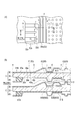
- the cooling medium flow path 80 includes a constricted portion 81 having a protrusion 32a and a recessed portion 32b, and a common portion 82 common to the recessed portion shape forming the cooling medium seal portion 90B. And. Further, the cooling medium flow path 80 includes a diffuser portion 83 that diffuses the cooling medium in the short direction and a power generation portion cooling portion 84 that cools the power generation portion 23.
- the constricted portion 81 is a cooling medium flow path 80 in a section ac in FIG.
- the cooling medium supplied from the cooling medium introduction hole ML2 passes through the narrowed portion 81, the cooling medium is rectified and a flow toward the common portion 82 is formed.
- the common part 82 is the cooling medium flow path 80 in the cd section of FIG. In the common portion 82, a flow path extending in the vertical direction of FIG. Therefore, most of the cooling medium flowing into the common portion 82 from the narrowed portion 81 flows into the diffuser portion 83, while a part of the cooling medium flows in the vertical direction in FIG.
- the diffuser part 83 is a cooling medium flow path 80 in the right section from d in FIG. 6, and is a part that communicates the constriction part 81 and the power generation part cooling part 84.
- the diffuser portion 83 has a function of diffusing the cooling medium flowing in through the narrowed portion 81 in the short direction (vertical direction in FIG. 6A) and flowing it to the power generating portion cooling portion 84. As shown in FIG. 6 f, a portion of the separator 30 that forms the diffuser portion 83 is provided with a plurality of hemispherical protrusions 32 c that protrude toward the adjacent separator. The diffusion of the cooling medium passing through the diffuser portion 83 is promoted.
- the power generation unit cooling unit 84 is provided in a portion overlapping the power generation unit 23 of the membrane electrode assembly 20 in the separator as viewed from the stacking direction.
- the power generation section cooling section 84 is a plurality of straight flow paths formed by providing a plurality of uneven shapes 31 and 41 that are parallel to each other. Then, when the cooling medium passes through the power generation section cooling section 84, the heat generated in the power generation section 23 that becomes high temperature due to the exothermic reaction during power generation is absorbed by the cooling medium, and the power generation section 23 is cooled.
- the cooling medium supplied from the cooling medium introduction hole ML2 to the cooling medium flow path 80 flows from the common portion 82 into the recess 33a on the back side of the cooling medium seal protrusion 92B formed on the cooling medium introduction hole ML2 side. .
- the cooling medium seal protrusion 92B and the gas seal protrusion 92A share a common protrusion. That is, the recess 33a on the back side of the cooling medium seal projection 92B communicates with the recess 33a on the back side of the gas seal projection 92A. Therefore, as shown in FIG. 7, the cooling medium flows into the recess 33a on the gas seal side, and there is a possibility that a side flow g2 that bypasses the power generation section cooling section 84 and flows toward the cooling medium discharge hole MR2 may occur.
- the flow g of the cooling medium may branch into a regular flow g1 that passes through the power generation unit cooling unit 84 and a side flow g2 that bypasses the power generation unit cooling unit 84 (see FIG. 7). .
- the side flow g2 arises, since the regular flow g1 which passes the electric power generation part cooling part 84 will decrease, the cooling performance of the electric power generation part 23 may fall.
- the generation of the side flow g2 that bypasses the electric part cooling unit 84 is suppressed, and the decrease in the normal flow g1 passing through the power generation unit cooling unit 84 can be suppressed as much as possible.
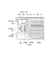
- the resistance portion 50 is provided on at least one of the gas seal protrusion 92A and the cooling medium seal protrusion 92B so that the flow of the cooling medium in the direction away from the power generation section cooling section 84 (side flow g2) can be suppressed. I made it.
- a throttle part 51 resistor part 50
- the narrowed portion 51 can be formed by reducing the depth of the concave portion 33a formed on the back side of the seal projection 92 or reducing the lateral width of the concave portion 33a.
- the gas seal projection 92A is provided with the throttle portion 51 in which the depth of the concave portion 33a is reduced, and the cooling medium seal projection 92B that is located on the downstream side of the cooling medium introduction hole ML2 and extends in the short direction.
- a narrowed portion 51 in which the lateral width of the recess 33a is narrowed is provided.
- the outer peripheral seal projection 92C is also provided with a throttle portion 51 in which the depth of the concave portion 33a is reduced.
- the cooling medium easily flows in the recess 33a formed on the back side of the seal projection 92, and the side flow g2 is easily generated.
- the throttle part 51 as the resistance part 50 is formed on the seal protrusion 92.
- the flow passage cross-sectional area in the passage direction of the cooling medium in the throttle portion 51 becomes smaller than the flow passage cross-sectional area of the recess 33a in the portion where the throttle portion 51 is not formed. Therefore, the pressure loss when the cooling medium passes through the recess 33a formed on the back side of the seal projection 92 can be increased.
- generation of the side flow g2 of the cooling medium can be suppressed, and the normal flow g1 passing through the power generation unit cooling unit 84 can be increased.
- by increasing the normal flow g1 passing through the power generation unit cooling unit 84 it is possible to suppress the cooling efficiency of the power generation unit 23 from being decreased.
- the adhesive seal material 91 between the membrane electrode assembly 20 and the separator 30 is applied thickly.
- the fuel cell stack FS includes the membrane electrode assembly 20 having the power generation unit 23 and the two separators 30 and 40 that sandwich the membrane electrode assembly 20.
- a fuel cell module M in which cells C are stacked is provided.
- the fuel cell C is introduced with gas introduction holes ML1 and 3 through which power generation gas is introduced, gas discharge holes MR1 and 3 through which power generation gas is discharged, and a cooling medium for cooling the power generation unit.
- a cooling medium introduction hole ML2 and a cooling medium discharge hole MR2 through which the cooling medium is discharged are formed.
- the power generation unit 23 is disposed between the two separators 30 and 40 in the fuel cell C, and a gas flow path 70 communicating with the gas introduction holes ML1 and ML3 and the gas discharge holes MR1 and 3 is formed. Has been.
- the fuel battery cell C includes a gas seal portion 90A that suppresses the outflow of power generation gas from the gas introduction holes ML1, 3, gas discharge holes MR1, 3, and the gas flow path 70, separators 30, 40, and membrane electrodes.
- a cooling medium seal portion 90B that suppresses the inflow of the cooling medium to and from the joined body 20 is formed.
- a cooling medium having a power generation unit cooling unit 84 that communicates with the cooling medium introduction hole ML2 and the cooling medium discharge hole MR2 and cools the power generation unit 23.
- a flow path 80 is formed.
- gas seal portion 90A protrudes from at least one of the two separators 30 and 40 in the fuel cell C to the membrane electrode assembly side, and the coolant flows on the side opposite to the membrane electrode assembly side.
- a gas seal projection 92 ⁇ / b> A in which a recess 33 a that becomes the path 80 is formed is provided.
- cooling medium seal portion 90B protrudes from at least one of the two separators 30 and 40 in the fuel cell C to the membrane electrode assembly side, and on the opposite side to the membrane electrode assembly side.
- a cooling medium seal protrusion 92 ⁇ / b> B in which a recess 33 a that becomes the flow path 80 is formed is provided.
- At least one of the gas seal protrusion 90A and the cooling medium seal protrusion 90B is provided with a resistance portion 50 that suppresses the flow of the cooling medium in the direction away from the power generation portion cooling portion 84.
- the recess 33a formed on the back side of the seal projection 92 is used as the cooling medium flow path 80, it is not necessary to take an extra space for forming the seal projection 92. As a result, it is possible to reduce the size of the separators 30 and 40, and consequently, it is possible to reduce the size of the fuel cell stack FS.
- At least one of the gas seal protrusion 92A and the cooling medium seal protrusion 92B is provided with a resistance section 50 that suppresses the flow of the cooling medium in the direction away from the power generation section cooling section 84 (side flow g2). As a result, more cooling medium flows to the power generation unit cooling unit 84, and it is possible to more reliably suppress deterioration of the cooling efficiency.
- the pressure loss generated when the cooling medium passes through the recess 33a is increased by the resistance unit 50, thereby suppressing the flow of the cooling medium.
- the resistance portion 50 has the throttle portion 51 formed on the gas seal protrusion 90A or the cooling medium seal protrusion 90B.
- the throttle portion 51 By forming the throttle portion 51, the pressure loss when the cooling medium passes through the recess 33a formed on the back side of the seal projection 92 can be increased, and the occurrence of the side flow g2 of the cooling medium is suppressed. Will be able to. As a result, it is possible to suppress the cooling efficiency of the power generation unit 23 from decreasing.
- the part 50 is provided.
- the present embodiment is different from the first embodiment in that the resistance portion 50 is provided by forming the bent portion 52 on at least one of the gas seal projection 92A and the cooling medium seal projection 92B. ing.
- the bent portion 52 is formed by bending a part of the cooling medium seal projection 90B in a staggered manner.
- Providing such a resistance portion 50 can also increase the pressure loss when the cooling medium passes through the recess 33a formed on the back side of the seal projection 92, and suppress the generation of the side flow g2 of the cooling medium. Will be able to.
- the part 50 is provided.
- the separator 30 communicates with the recess 33 a and the flow of the cooling medium in the direction away from the power generation unit cooling unit 84 is directed to the power generation unit cooling unit 84.
- a second recess 53 that is changed into a flow is formed.
- the flow of the cooling medium in the direction away from the power generation section cooling section 84 can be returned to the flow toward the power generation section cooling section 84.
- the resistance part 50 is provided in the downstream rather than the communication part 53a with the 2nd recessed part 53 in the recessed part 33a.
- the second recess 53 that changes the flow of the cooling medium in the direction away from the power generation unit cooling unit 84 to the flow toward the power generation unit cooling unit 84 is provided. It communicates with the recess 33a. Therefore, the side flow g2 can be efficiently returned by the normal flow g1.
- the resistance portion 50 is provided on the downstream side of the communication portion 53a with the second recess 53 in the recess 33a. Therefore, there is an advantage that the cooling medium easily stays in the vicinity of the second recess 53, and the side flow g2 can be more efficiently returned to the normal flow g1.
- the part 50 is provided.
- the resistance portion 50 has a blocking portion 54 that blocks the communication of the recess 33a.
- the blocking portion 54 is formed by providing the separator 30 with a flat section without providing the recess 33a partially.
- a blocking portion 54 is provided at a connecting portion between the gas seal projection 92A and the cooling medium seal projection 92B that is located downstream of the cooling medium introduction hole ML2 and extends in the short direction. Forming.
- the resistance part 50 has the interruption
- the gas seal or the cooling medium seal in the blocking portion 54 is formed. Needs to be formed only with an adhesive sealant. Therefore, the holding power of the adhesive seal material may be weakened by the power generation gas generated between the membrane electrode assembly 20 and the separators 30 and 40 or the pressure h of the cooling medium.
- At least one of the start point 54a and the end point 54b of the blocking portion 54 in the gas seal projection 92A or the cooling medium seal projection 92B is provided between the membrane electrode assembly 20 and the separators 30 and 40. You may make it form the holding
- FIG. 15A illustrates the holding portion 55 formed by cutting both the start point 54a and the end point 54b of the blocking portion 54 into a rectangular shape.
- the adhesive sealing material 91 can be hooked on the start point 54a and the end point 54b. Therefore, even if the gas pressure h is applied to the gas seal portion between the membrane electrode assembly 20 and the separators 30 and 40 in the flat section, it is possible to prevent the holding force of the adhesive seal material 91 from being reduced. .
- FIG. 15B illustrates a holding portion 55 formed by a shape in which the adhesive seal material 91 is squeezed and sandwiched between the start point 54a and the end point 54b.
- FIG. 15C illustrates the holding portion 55 formed by bending the start point 54a and the end point 54b into a zigzag shape.
- the shape of the start point and the end point is not limited to this, and various shapes can be adopted as long as the shape increases the holding power of the adhesive seal material.
Landscapes
- Life Sciences & Earth Sciences (AREA)
- Engineering & Computer Science (AREA)
- Manufacturing & Machinery (AREA)
- Sustainable Development (AREA)
- Sustainable Energy (AREA)
- Chemical & Material Sciences (AREA)
- Chemical Kinetics & Catalysis (AREA)
- Electrochemistry (AREA)
- General Chemical & Material Sciences (AREA)
- Fuel Cell (AREA)
Abstract
Description
本実施形態にかかる燃料電池スタックFSは、図1(B)に示すように、複数の燃料電池セルCが積層された燃料電池モジュールMを有している。
本実施形態にかかるセパレータ30Aにおいても、ガスシール突起92Aおよび冷却媒体シール突起92Bの少なくともいずれか一方に、冷却媒体の発電部冷却部84から外れる方向への流れ(脇流れg2)を抑制する抵抗部50を設けている。
本実施形態にかかるセパレータ30Bにおいても、ガスシール突起92Aおよび冷却媒体シール突起92Bの少なくともいずれか一方に、冷却媒体の発電部冷却部84から外れる方向への流れ(脇流れg2)を抑制する抵抗部50を設けている。
本実施形態にかかるセパレータ30Cにおいても、ガスシール突起92Aおよび冷却媒体シール突起92Bの少なくともいずれか一方に、冷却媒体の発電部冷却部84から外れる方向への流れ(脇流れg2)を抑制する抵抗部50を設けている。
M 燃料電池モジュール
C 燃料電池セル
20 膜電極接合体
23 発電部
30、30A、30B、30C アノード側セパレータ
33a 凹部
40 カソード側セパレータ
50 抵抗部
51 絞り部
52 屈曲部
53 第2の凹部
54 遮断部
54a 始端
54b 終端
55 保持部
70 ガス流路
80 冷却媒体流路
84 発電部冷却部
90 シール部
90A ガスシール部
90B 冷却媒体シール部
91 シール材
92 シール突起
92A ガスシール突起
92B 冷却媒体突起
ML1 酸素含有ガス供給用(ガス導入孔)
ML2 冷却媒体供給用(冷却媒体導入孔)
ML3 水素含有ガス供給用(ガス導入孔)
MR1 酸素含有ガス排出用(ガス排出孔)
MR2 冷却媒体排出用(冷却媒体排出孔)
MR3 水素含有ガス排出用(ガス排出孔)
Claims (6)
- 発電部を有する膜電極接合体と、前記膜電極接合体を挟持する2枚のセパレータと、を有する燃料電池セルが積層された燃料電池モジュールを備える燃料電池スタックにおいて、
前記燃料電池セルには、発電用ガスが導入されるガス導入孔と、前記発電用ガスが排出されるガス排出孔と、発電部冷却用の冷却媒体が導入される冷却媒体導入孔と、前記冷却媒体が排出される冷却媒体排出孔と、が形成されており、
前記燃料電池セルにおける前記2枚のセパレータの間には、前記発電部が配置されるとともに、前記ガス導入孔および前記ガス排出孔に連通するガス流路が形成されており、
前記燃料電池セルには、前記ガス導入孔、前記ガス排出孔および前記ガス流路からの前記発電用ガスの流出を抑制するガスシール部と、前記セパレータと前記膜電極接合体との間への前記冷却媒体の流入を抑制する冷却媒体シール部と、が形成されており、
前記燃料電池モジュールの互いに隣り合う燃料電池セルの間には、前記冷却媒体導入孔および前記冷却媒体排出孔に連通するとともに、前記発電部を冷却する発電部冷却部を有する冷却媒体流路が形成されており、
前記ガスシール部は、前記燃料電池セルにおける前記2枚のセパレータのうち少なくともいずれか一方のセパレータから前記膜電極接合体側に突出するとともに、前記膜電極接合体側とは反対側に前記冷却媒体流路となる凹部が形成されたガスシール突起を備えており、
前記冷却媒体シール部は、前記燃料電池セルにおける前記2枚のセパレータのうち少なくともいずれか一方のセパレータから前記膜電極接合体側に突出するとともに、前記膜電極接合体側とは反対側に前記冷却媒体流路となる凹部が形成された冷却媒体シール突起を備えており、
前記ガスシール突起および前記冷却媒体シール突起の少なくともいずれか一方に、前記冷却媒体の前記発電部冷却部から外れる方向への流れを抑制する抵抗部が設けられていることを特徴とする燃料電池スタック。 - 前記冷却媒体が前記凹部を通過する際に生じる圧力損失を前記抵抗部によって増大させることで、前記冷却媒体の流れを抑制することを特徴とする請求項1に記載の燃料電池スタック。
- 前記抵抗部が前記ガスシール突起または前記冷却媒体シール突起に形成された絞り部を有することを特徴とする請求項1または請求項2に記載の燃料電池スタック。
- 前記セパレータには、前記凹部に連通するとともに、前記冷却媒体の前記発電部冷却部から外れる方向への流れを、前記発電部冷却部に向かう流れに変化させる第2の凹部が形成されており、
前記抵抗部が、前記凹部における前記第2の凹部との連通部よりも下流側に設けられていることを特徴とする請求項1~3のうちいずれか1項に記載の燃料電池スタック。 - 前記抵抗部が前記凹部の連通を遮断する遮断部を有することを特徴とする請求項1に記載の燃料電池スタック。
- 前記ガスシール突起または前記冷却媒体シール突起における前記遮断部の始点および終点の少なくとも一方には、前記膜電極接合体と前記セパレータとの間に設けられる接着シール材を保持可能な保持部が形成されていることを特徴とする請求項5に記載の燃料電池スタック。
Priority Applications (7)
| Application Number | Priority Date | Filing Date | Title |
|---|---|---|---|
| KR1020187001521A KR101880880B1 (ko) | 2015-07-17 | 2015-07-17 | 연료 전지 스택 |
| CN201580081744.3A CN107851815B (zh) | 2015-07-17 | 2015-07-17 | 燃料电池组 |
| PCT/JP2015/070557 WO2017013710A1 (ja) | 2015-07-17 | 2015-07-17 | 燃料電池スタック |
| CA2992838A CA2992838C (en) | 2015-07-17 | 2015-07-17 | Fuel cell stack |
| JP2017529183A JP6458867B2 (ja) | 2015-07-17 | 2015-07-17 | 燃料電池スタック |
| US15/745,309 US10340533B2 (en) | 2015-07-17 | 2015-07-17 | Fuel cell stack |
| EP15898872.5A EP3327842B1 (en) | 2015-07-17 | 2015-07-17 | Fuel cell stack |
Applications Claiming Priority (1)
| Application Number | Priority Date | Filing Date | Title |
|---|---|---|---|
| PCT/JP2015/070557 WO2017013710A1 (ja) | 2015-07-17 | 2015-07-17 | 燃料電池スタック |
Publications (1)
| Publication Number | Publication Date |
|---|---|
| WO2017013710A1 true WO2017013710A1 (ja) | 2017-01-26 |
Family
ID=57835315
Family Applications (1)
| Application Number | Title | Priority Date | Filing Date |
|---|---|---|---|
| PCT/JP2015/070557 Ceased WO2017013710A1 (ja) | 2015-07-17 | 2015-07-17 | 燃料電池スタック |
Country Status (7)
| Country | Link |
|---|---|
| US (1) | US10340533B2 (ja) |
| EP (1) | EP3327842B1 (ja) |
| JP (1) | JP6458867B2 (ja) |
| KR (1) | KR101880880B1 (ja) |
| CN (1) | CN107851815B (ja) |
| CA (1) | CA2992838C (ja) |
| WO (1) | WO2017013710A1 (ja) |
Cited By (5)
| Publication number | Priority date | Publication date | Assignee | Title |
|---|---|---|---|---|
| CN109802156A (zh) * | 2017-11-17 | 2019-05-24 | 本田技研工业株式会社 | 燃料电池用金属隔板以及燃料电池 |
| JP2020107446A (ja) * | 2018-12-26 | 2020-07-09 | トヨタ自動車株式会社 | 燃料電池スタック |
| JP2020522089A (ja) * | 2017-05-30 | 2020-07-27 | レインツ デッチタングス ゲー エム ベー ハー | 電気化学システム用のセパレータプレート |
| JP2020136060A (ja) * | 2019-02-19 | 2020-08-31 | トヨタ自動車株式会社 | 燃料電池 |
| WO2025204455A1 (ja) * | 2024-03-29 | 2025-10-02 | 本田技研工業株式会社 | 燃料電池スタック |
Families Citing this family (4)
| Publication number | Priority date | Publication date | Assignee | Title |
|---|---|---|---|---|
| CN109830693A (zh) * | 2019-01-15 | 2019-05-31 | 安徽明天氢能科技股份有限公司 | 一种燃料电池单极板结构 |
| JP7297805B2 (ja) * | 2021-03-19 | 2023-06-26 | 本田技研工業株式会社 | 燃料電池スタック |
| DE102021214194A1 (de) | 2021-12-13 | 2023-06-15 | Robert Bosch Gesellschaft mit beschränkter Haftung | Brennstoffzellensystem und Bipolarplatte für ein Brennstoffzellensystem |
| CN114864961B (zh) * | 2022-05-31 | 2024-12-17 | 上海电气集团股份有限公司 | 燃料电池的双极板 |
Citations (5)
| Publication number | Priority date | Publication date | Assignee | Title |
|---|---|---|---|---|
| JP2004119121A (ja) * | 2002-09-25 | 2004-04-15 | Honda Motor Co Ltd | 燃料電池 |
| JP2006269208A (ja) * | 2005-03-23 | 2006-10-05 | Toyota Motor Corp | 燃料電池及び燃料電池用セパレータ |
| JP2011222393A (ja) * | 2010-04-13 | 2011-11-04 | Toyota Motor Corp | 燃料電池 |
| JP2013201091A (ja) * | 2012-03-26 | 2013-10-03 | Honda Motor Co Ltd | 燃料電池 |
| JP2015095315A (ja) * | 2013-11-11 | 2015-05-18 | トヨタ自動車株式会社 | 燃料電池に用いられるセパレータおよび燃料電池 |
Family Cites Families (5)
| Publication number | Priority date | Publication date | Assignee | Title |
|---|---|---|---|---|
| JP4928067B2 (ja) * | 2004-03-25 | 2012-05-09 | 本田技研工業株式会社 | 燃料電池及び燃料電池用金属セパレータ |
| DE102007048184B3 (de) | 2007-10-02 | 2009-01-22 | Reinz-Dichtungs-Gmbh | Elektrochemisches System und Biopolarplatte |
| WO2013132860A1 (en) | 2012-03-09 | 2013-09-12 | Nissan Motor Co., Ltd. | Fuel cell stack and seal plate used for the same |
| US9088015B2 (en) | 2012-03-26 | 2015-07-21 | Honda Motor Co., Ltd. | Fuel cell comprising water discharge channel formed by a corrugated section |
| JP6024645B2 (ja) * | 2013-11-15 | 2016-11-16 | トヨタ自動車株式会社 | 燃料電池用セパレータおよび燃料電池スタック |
-
2015
- 2015-07-17 CA CA2992838A patent/CA2992838C/en active Active
- 2015-07-17 WO PCT/JP2015/070557 patent/WO2017013710A1/ja not_active Ceased
- 2015-07-17 EP EP15898872.5A patent/EP3327842B1/en not_active Not-in-force
- 2015-07-17 US US15/745,309 patent/US10340533B2/en active Active
- 2015-07-17 KR KR1020187001521A patent/KR101880880B1/ko not_active Expired - Fee Related
- 2015-07-17 JP JP2017529183A patent/JP6458867B2/ja not_active Expired - Fee Related
- 2015-07-17 CN CN201580081744.3A patent/CN107851815B/zh not_active Expired - Fee Related
Patent Citations (5)
| Publication number | Priority date | Publication date | Assignee | Title |
|---|---|---|---|---|
| JP2004119121A (ja) * | 2002-09-25 | 2004-04-15 | Honda Motor Co Ltd | 燃料電池 |
| JP2006269208A (ja) * | 2005-03-23 | 2006-10-05 | Toyota Motor Corp | 燃料電池及び燃料電池用セパレータ |
| JP2011222393A (ja) * | 2010-04-13 | 2011-11-04 | Toyota Motor Corp | 燃料電池 |
| JP2013201091A (ja) * | 2012-03-26 | 2013-10-03 | Honda Motor Co Ltd | 燃料電池 |
| JP2015095315A (ja) * | 2013-11-11 | 2015-05-18 | トヨタ自動車株式会社 | 燃料電池に用いられるセパレータおよび燃料電池 |
Cited By (12)
| Publication number | Priority date | Publication date | Assignee | Title |
|---|---|---|---|---|
| JP2020522089A (ja) * | 2017-05-30 | 2020-07-27 | レインツ デッチタングス ゲー エム ベー ハー | 電気化学システム用のセパレータプレート |
| JP2022023937A (ja) * | 2017-05-30 | 2022-02-08 | レインツ デッチタングス ゲー エム ベー ハー | 電気化学システム用のセパレータプレート |
| JP7306610B2 (ja) | 2017-05-30 | 2023-07-11 | レインツ デッチタングス ゲー エム ベー ハー | 電気化学システム用のセパレータプレート |
| CN109802156A (zh) * | 2017-11-17 | 2019-05-24 | 本田技研工业株式会社 | 燃料电池用金属隔板以及燃料电池 |
| JP2019096382A (ja) * | 2017-11-17 | 2019-06-20 | 本田技研工業株式会社 | 燃料電池用金属セパレータ及び燃料電池 |
| US11189848B2 (en) | 2017-11-17 | 2021-11-30 | Honda Motor Co., Ltd. | Fuel cell metal separator and fuel cell |
| CN109802156B (zh) * | 2017-11-17 | 2022-02-25 | 本田技研工业株式会社 | 燃料电池用金属隔板以及燃料电池 |
| JP2020107446A (ja) * | 2018-12-26 | 2020-07-09 | トヨタ自動車株式会社 | 燃料電池スタック |
| JP7077936B2 (ja) | 2018-12-26 | 2022-05-31 | トヨタ自動車株式会社 | 燃料電池スタック |
| JP2020136060A (ja) * | 2019-02-19 | 2020-08-31 | トヨタ自動車株式会社 | 燃料電池 |
| JP7074094B2 (ja) | 2019-02-19 | 2022-05-24 | トヨタ自動車株式会社 | 燃料電池 |
| WO2025204455A1 (ja) * | 2024-03-29 | 2025-10-02 | 本田技研工業株式会社 | 燃料電池スタック |
Also Published As
| Publication number | Publication date |
|---|---|
| US20190013528A1 (en) | 2019-01-10 |
| JP6458867B2 (ja) | 2019-01-30 |
| EP3327842B1 (en) | 2019-04-17 |
| KR20180019196A (ko) | 2018-02-23 |
| CA2992838A1 (en) | 2017-01-26 |
| US10340533B2 (en) | 2019-07-02 |
| KR101880880B1 (ko) | 2018-07-20 |
| EP3327842A1 (en) | 2018-05-30 |
| JPWO2017013710A1 (ja) | 2018-05-24 |
| CN107851815A (zh) | 2018-03-27 |
| EP3327842A4 (en) | 2018-05-30 |
| CA2992838C (en) | 2018-09-25 |
| CN107851815B (zh) | 2019-03-01 |
Similar Documents
| Publication | Publication Date | Title |
|---|---|---|
| JP6458867B2 (ja) | 燃料電池スタック | |
| JP5133616B2 (ja) | 燃料電池 | |
| CN109713344B (zh) | 发电单电池 | |
| US6815115B2 (en) | Fuel cell and fuel cell stack | |
| JP5077226B2 (ja) | セル積層体およびこれを備えた燃料電池 | |
| CN109802156B (zh) | 燃料电池用金属隔板以及燃料电池 | |
| US8206875B2 (en) | Fuel cell and separator for the same | |
| CN110690471B (zh) | 燃料电池用隔板构件以及燃料电池堆 | |
| JP2017117780A (ja) | 燃料電池モジュール | |
| JP2018098041A (ja) | 燃料電池スタック | |
| CN109950571B (zh) | 燃料电池 | |
| CN104205450B (zh) | 燃料电池 | |
| CA2602153C (en) | Fuel cell and fuel cell separator having a cooling medium regulating portion | |
| JP5365162B2 (ja) | 燃料電池 | |
| JP5144226B2 (ja) | 燃料電池 | |
| JP2006147258A (ja) | セパレータ及び燃料電池スタック | |
| JP2017147101A (ja) | 燃料電池 | |
| JP7790208B2 (ja) | 燃料電池スタック | |
| CN107534179B (zh) | 燃料电池堆 | |
| JP4197935B2 (ja) | 燃料電池スタック | |
| CN117223132A (zh) | 隔板 | |
| JP2004063094A (ja) | 燃料電池および燃料電池スタック | |
| JP2025121532A (ja) | 燃料電池スタック及び燃料電池のセパレータ | |
| JP2024104006A (ja) | 燃料電池用セパレータ及び燃料電池スタック | |
| JP2008047295A (ja) | 燃料電池およびその製造方法 |
Legal Events
| Date | Code | Title | Description |
|---|---|---|---|
| 121 | Ep: the epo has been informed by wipo that ep was designated in this application |
Ref document number: 15898872 Country of ref document: EP Kind code of ref document: A1 |
|
| ENP | Entry into the national phase |
Ref document number: 2017529183 Country of ref document: JP Kind code of ref document: A |
|
| ENP | Entry into the national phase |
Ref document number: 2992838 Country of ref document: CA Ref document number: 20187001521 Country of ref document: KR Kind code of ref document: A |
|
| NENP | Non-entry into the national phase |
Ref country code: DE |
|
| WWE | Wipo information: entry into national phase |
Ref document number: 2015898872 Country of ref document: EP |